CDW
-
Posts
7,760 -
Joined
-
Last visited
Content Type
Profiles
Forums
Gallery
Events
Everything posted by CDW
-
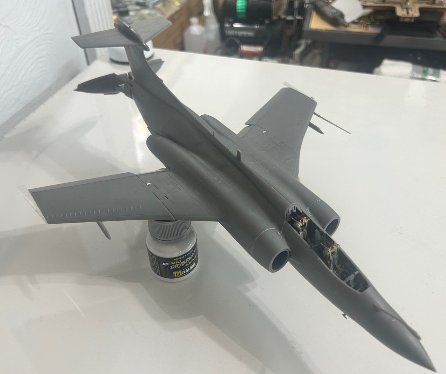
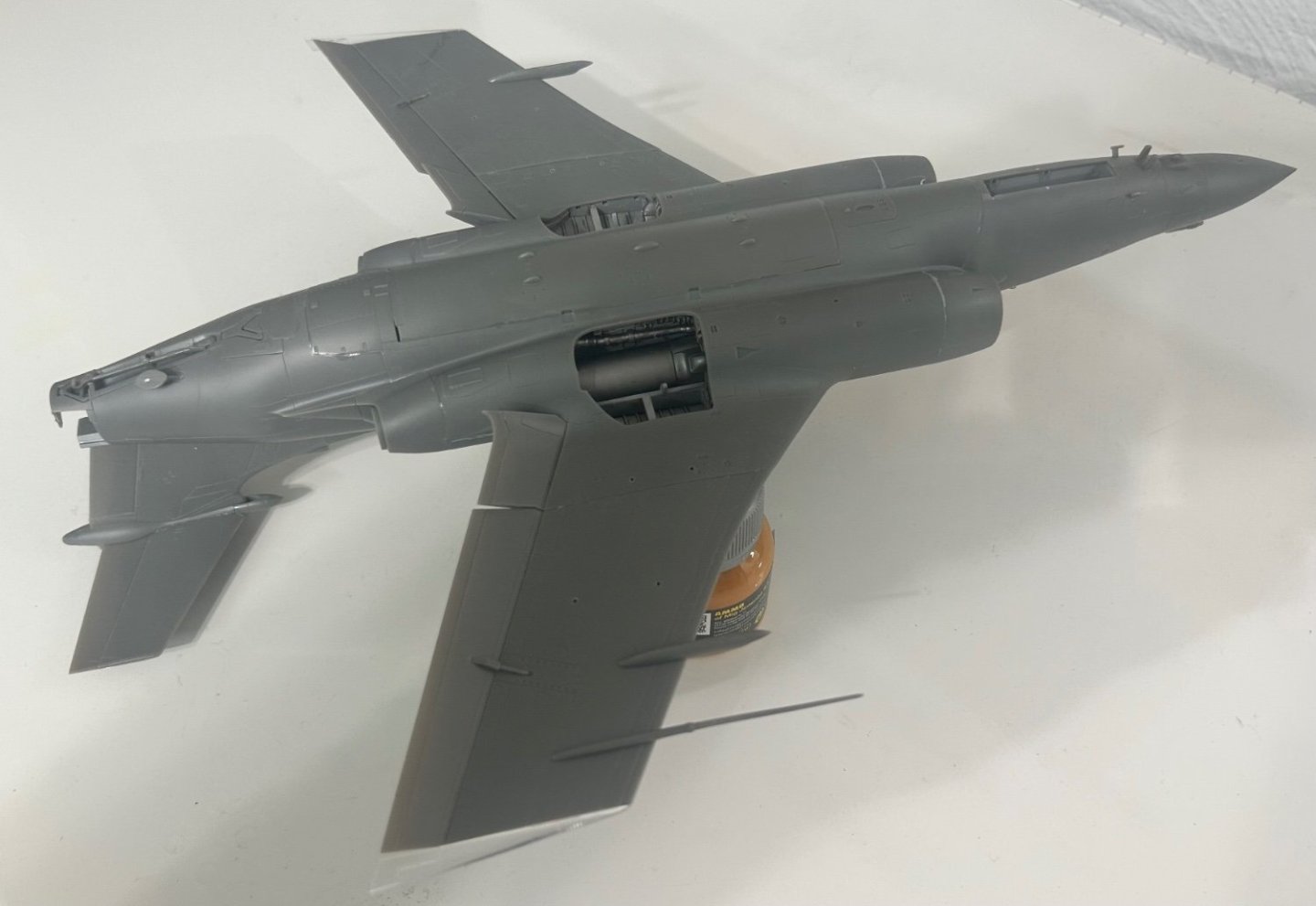
 Even though Mr Color Surfacer 1000 goes down very smooth, will wet sand gently with Tamiya extra fine sanding sponge before applying color coats.

- 332 replies
-
- 11
-

-
Didn't mean to infer it was. Simply that the old saying, to the victor go the spoils of war, is now, was then and will ever be true. Look back at history as far back as we know...the artisans, experts, and "scientists" have always been kept as spoils of war. ordinary men and women are expendable. That's the cold hard truth. There is no reason whatsoever for me to believe it would be any different today.
-
Paperclip A guy I knew was guard at a prisoner of war camp here in the USA during WW2. He told of the special prisoners kept here back then.
-
Can anybody say: Hans-Ulrich Udel? Talk about a ground target smasher, this was THE man. Over 500 tanks destroyed, ships including a battleship, a cruiser, dozens upon dozens of artillery emplacements and untold numbers of softskin vehicles. He was even credited with shooting down nine aircraft.
-
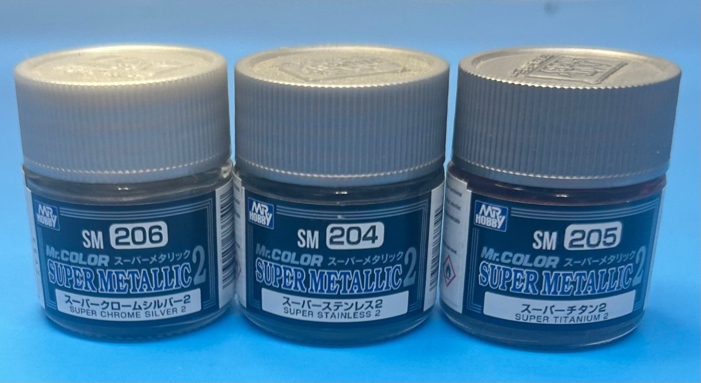
Mr Color has one out called super chrome silver, applied over gloss black through an airbrush. With a clear varnish it looks phenomenal. A couple of other “super” metallics in this particular line. Very fine pigments.
-
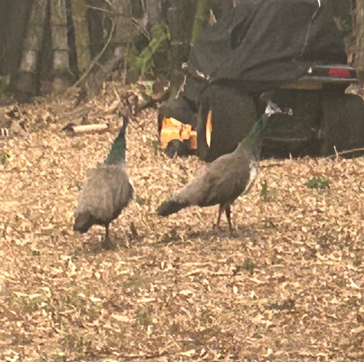
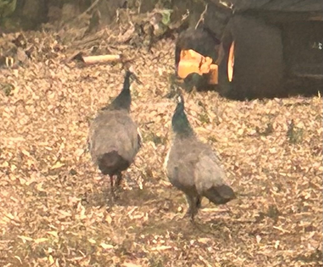
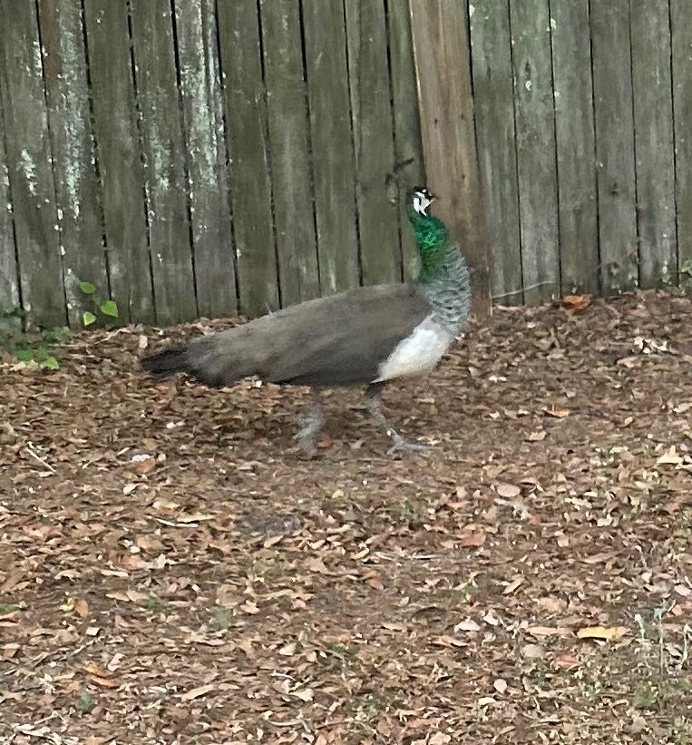
These peacocks came struttin’ through my back yard this afternoon. Both are females. The males don’t wander too far from home but send the females to scout around. These things are open season in Florida (for real), considered an invasive nuisance species along with the pythons and iguanas.

-
I would hate to be on the receiving end of those projectiles. They must have ripped through ground targets like mad.
-
That's an option to consider
-
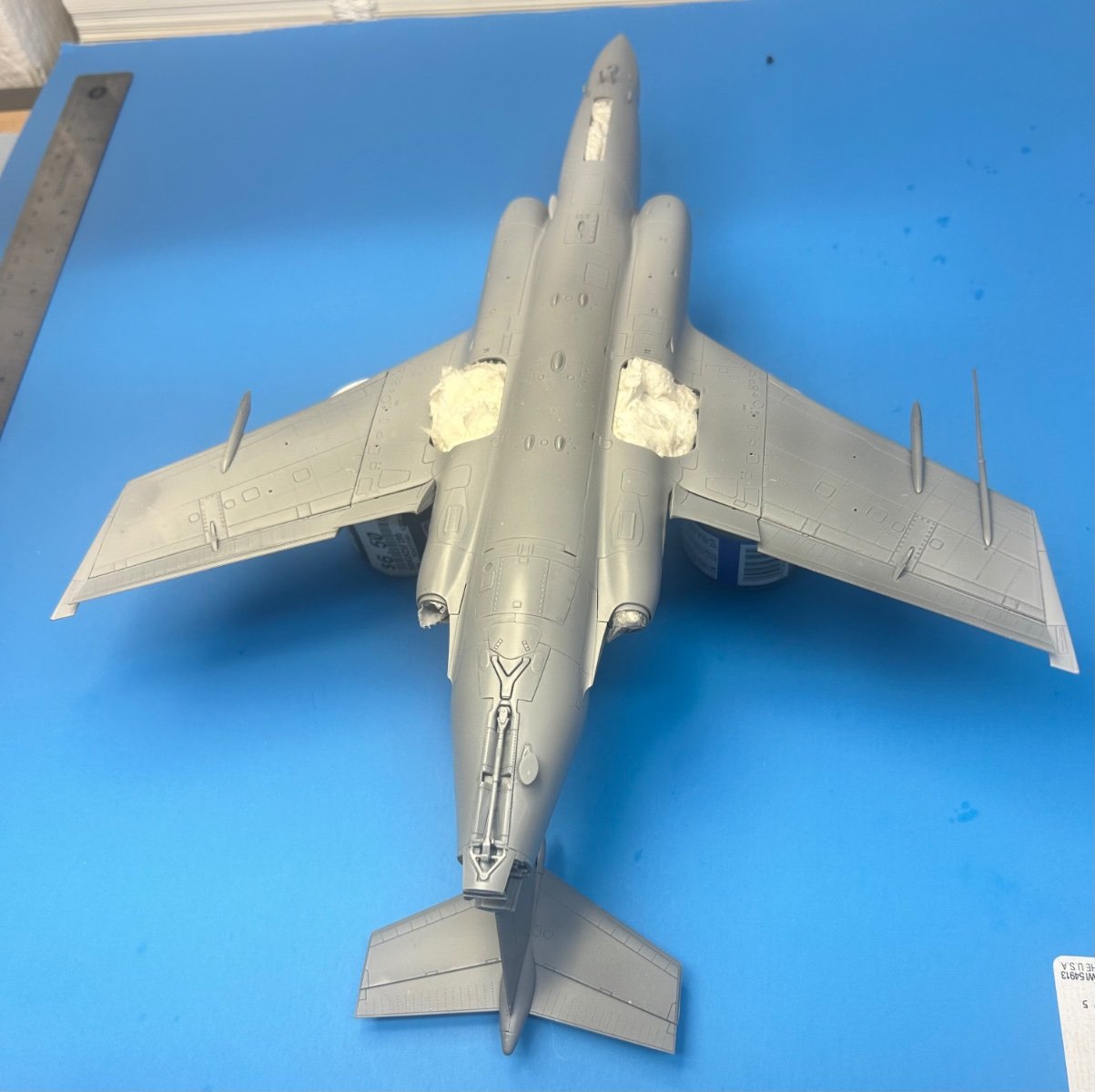
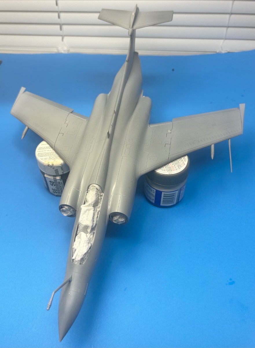
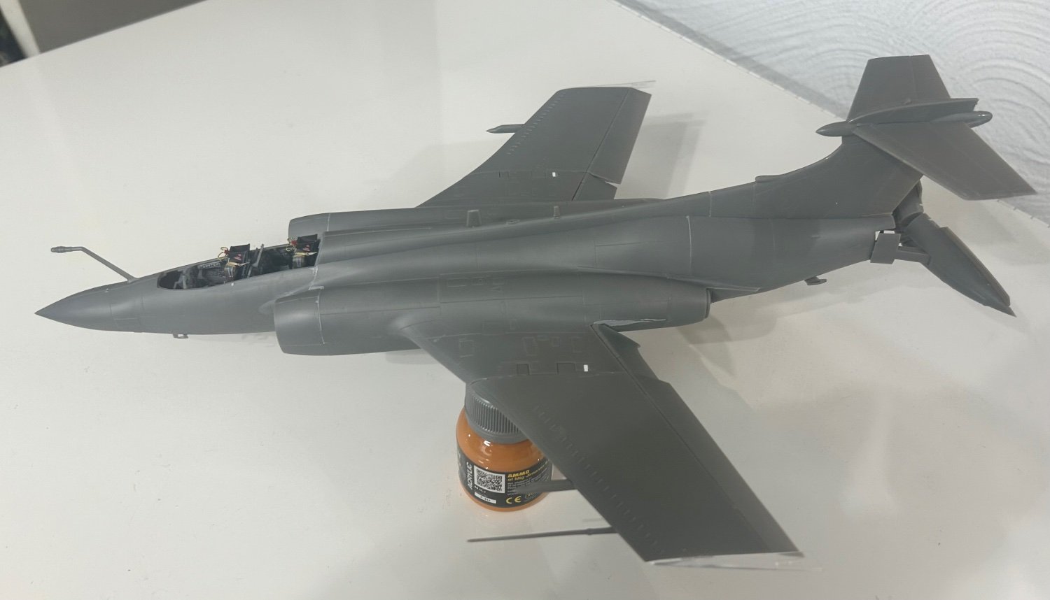
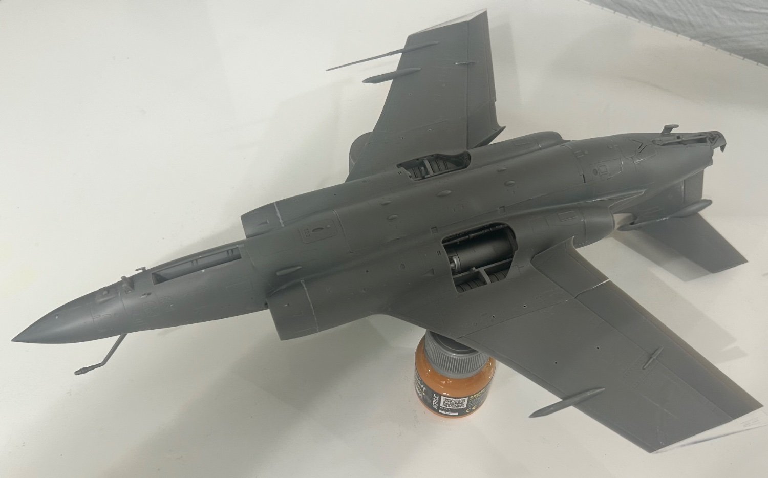
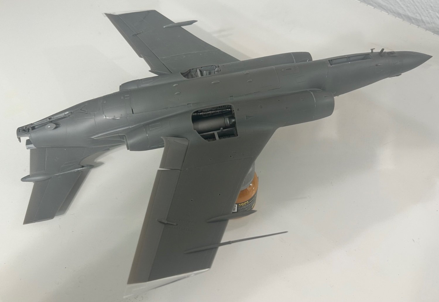
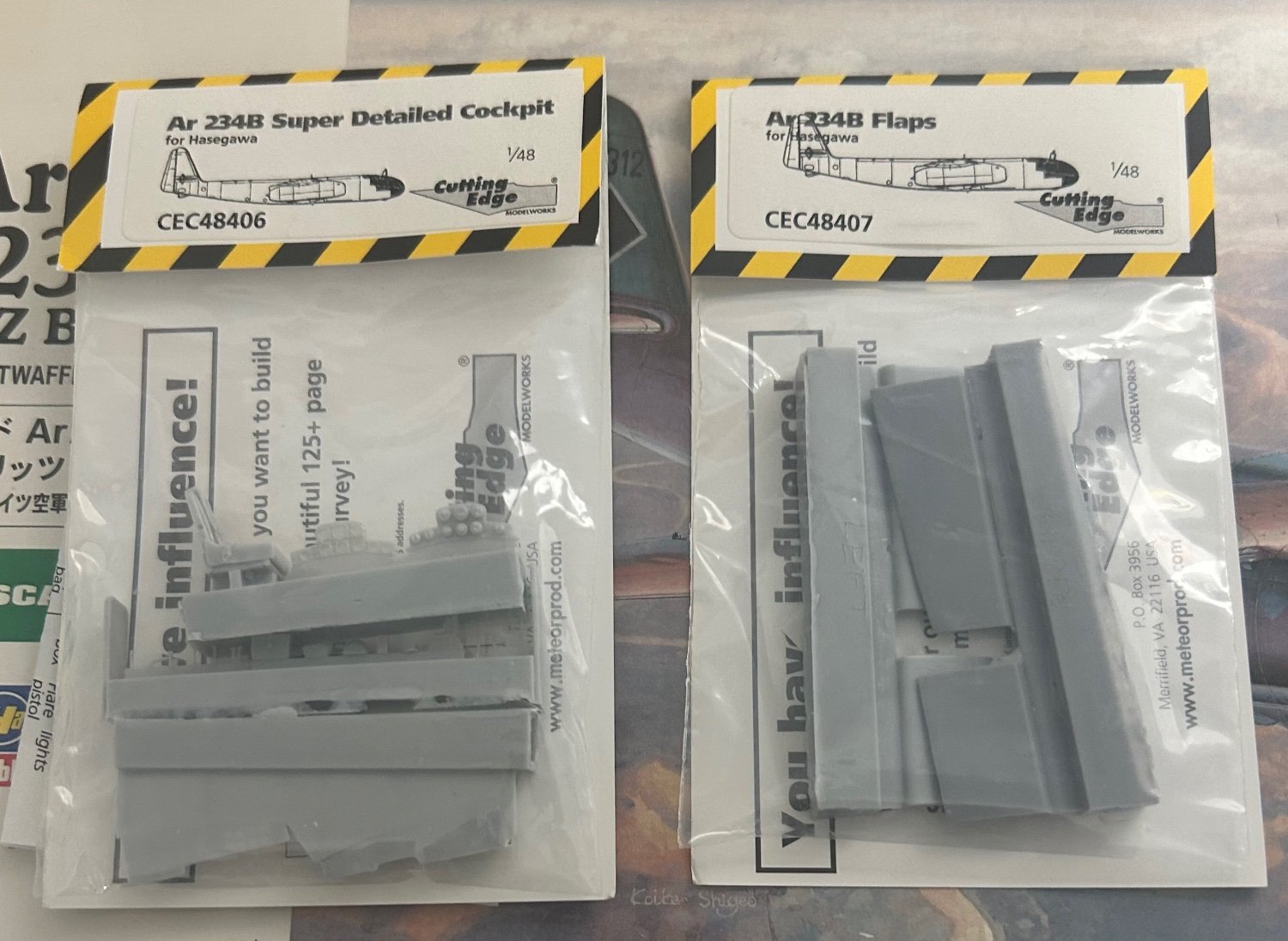
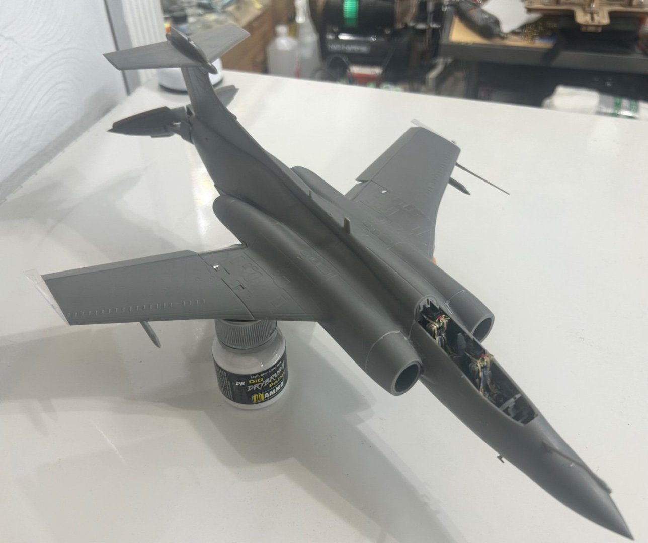
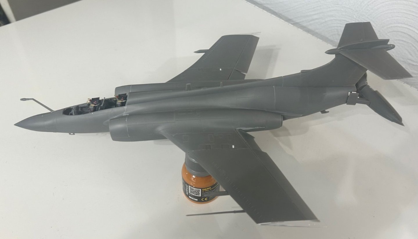
PS: The rings at the front of the intakes are left off as they will be painted silver and added after the rest of the model is painted. Better than masking later IMO.
-
Ready to test and touch up a few places if needed, then lay down a smooth coat of primer over the whole model. The S.2D I’m building has a detonation cord in the canopy. Other aircraft I’ve seen have white/light gray colored cords. I’m guessing it’s the same for the Buccaneer. Suggestions? Don't waste any money on aftermarket wheels or antennae for this model. The kit parts are as good and the wheels maybe better than the aftermarket ones. Perhaps they were intended for the old 90’s Airfix kit cause this kit doesn’t need them at all. I do recommend the cockpit set. It’s amazing.

- 332 replies
-
- 10
-
-
That looks super!
-
Has anyone heard from Popeye the Sailor (Denis)? Have not seen him around for a couple of months and am hoping all is well with him and his family.
-
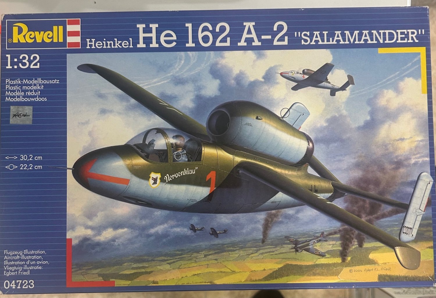
I've got the 1:32 scale big brother of this kit to do when I get a round to-it. You are an inspiration Andy. Your work is beautiful.
-
Great to know. Rare nowadays that companies will do that. My how things have changed over time and how much we once took for granted.
-
@AJohnson Have you noticed the kit has some of the parts necessary to turn this into an S.2B? Just realized the wingtips are there. Need a set of bulged bomb bay doors, a small change in ordnance along with a different decal sheet. Anything else? I see parts on the trees that are not being used.
-
Thanks Gary! I read that this new company is comprised of former employees of Wingnut Wings. That would explain the fine castings we see on the Spit.
-
Check out this new Spitfire Mk.1a kit. It's very very nice.
-
I found this photo of what is labeled as an S.2B in service with the RN, no bulged bomb bay. Confirms what EG said. XV867 | Blackburn Buccaneer S.2B | United Kingdom - Royal Navy | Victor A. Pisani | JetPhotos
-
Did not know that. Camo too, eh?
-
Thanks OC, some beautiful photos. I'm puzzled about the 2022 photos as they show up as a Royal Navy aircraft, but it's painted (camo) and carries the bulged bomb bay of the S.2B which is an RAF aircraft.
-
At the model show two weeks ago, they sold raffle tickets to raise money to help pay expenses. Tickets were a dollar each or thirty tickets for twenty dollars. I bought thirty tickets. There were multiple jars where the tickets could be placed with each jar representing a particular prize group. I put my tickets in a 1:32 aircraft jar, a 1:48 aircraft jar, a ship jar, and a paint & accessory jar. Multiple drawings were pulled each hour of the show and one grand prize drawing at the end. I hit one drawing in each of the four categories I entered. It was a lucky day I guess.


-
Here's what I have learned from my own puny research efforts: The first operational Buccaneer aircraft was the S.1 assigned to the RN The S.2 received upgraded, more fuel efficient Rolls Royce engines S,2A's had modified airframes and improved avionics, and transferred to the RAF S.2B's were modified S.2A's with a bulged bomb bay designed to carry an extra fuel tank as well as improved targeting systems carrying the Martel anti-shipping missiles and anti-radiation missile. Used by the RAF during the Gulf War. S.2D's (my model version) were RN S.2's upgraded to "full S.2B standards". Now, what I also know is that the S.2D does not have a bulged bomb bay. So this leads me to believe the "full S.2B standards" did not include the extra fuel tank or if it did, it was a smaller one as there are no bulged bomb bay doors. It does have the equal/same avionics and targeting systems of the S.2B
-
The weapons this aircraft version is modeled to carry are two TV Martel anti-shipping missiles and a single Martel AS.37 anti-radiation missile, The fourth pylon carries a Martel TV-guidance data link pod. So is this aircraft more like a Royal Navy version of a Wild Weasel? Seems like it to me. This is why I'm not sure if the bomb bay doors would remain operational. It's conceivable to me a fuel tank may possibly be added there as the slipper tanks don't appear on this version. Mind you, this is all wild speculation on my part.
-
I was hoping one of our friends in the UK may have superior knowledge about the aircraft they could share with us.
-
Oh wow...I did not know the kit supplied the instructions and materials (and jig?) for creating the spokes. Very nice but tedious for sure. If you don't mind me saying so, I would consider using your molded seat to create a silicon replica mold and then cast the seat from resin. Cover the resin seat with leather. It will be difficult to cover that seat because its probably too flexible. Resin opens up the possibility to use a contact cement which will not harm the resin but adhere leather to it.