HOLIDAY DONATION DRIVE - SUPPORT MSW - DO YOUR PART TO KEEP THIS GREAT FORUM GOING! (Only 27 donations so far out of 49,000 members - C'mon guys!)
×

genericDave
-
Posts
209 -
Joined
-
Last visited
Content Type
Profiles
Forums
Gallery
Events
Everything posted by genericDave
-
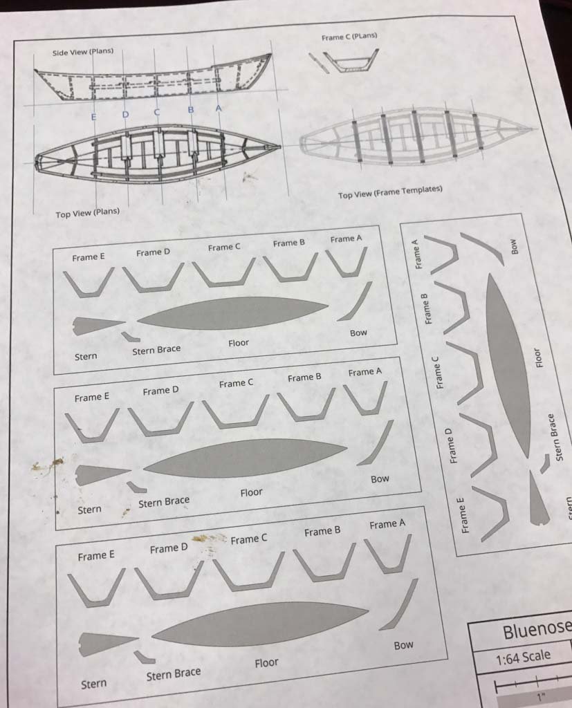
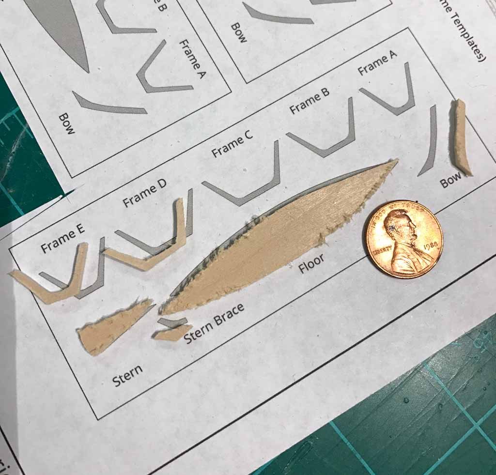
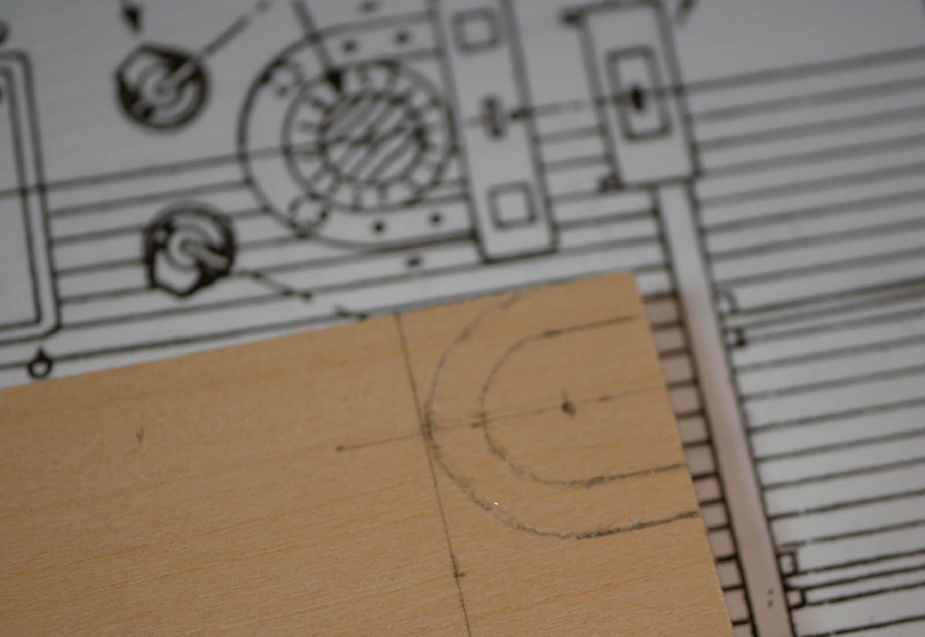
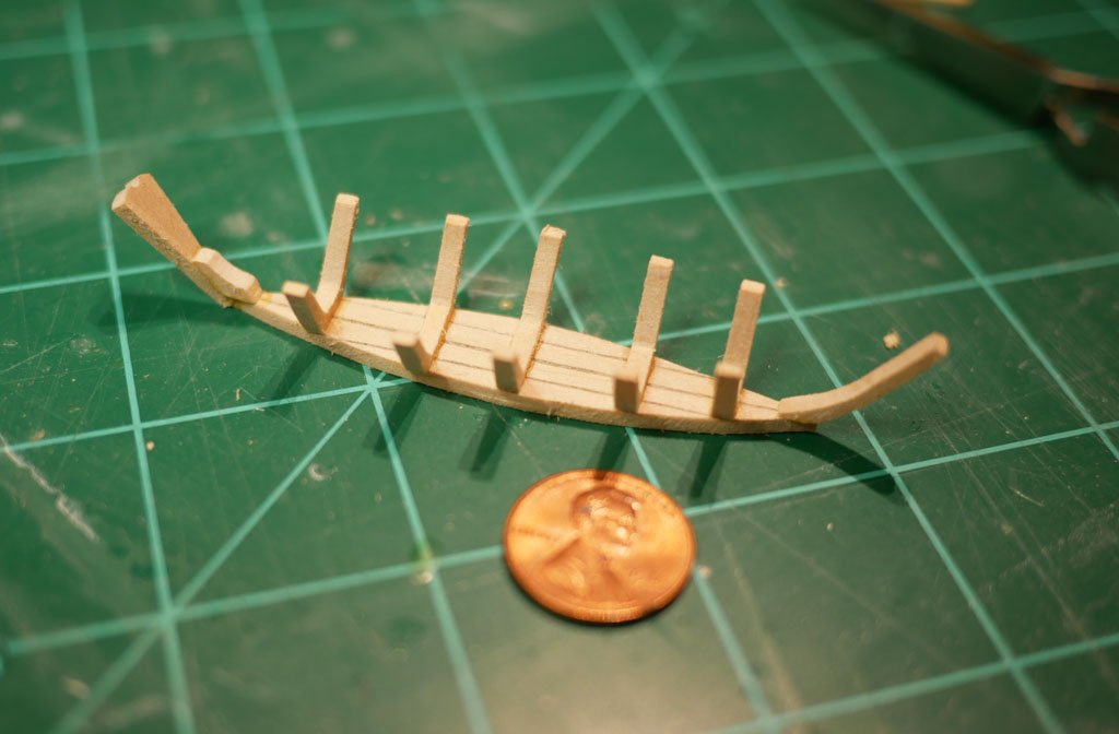
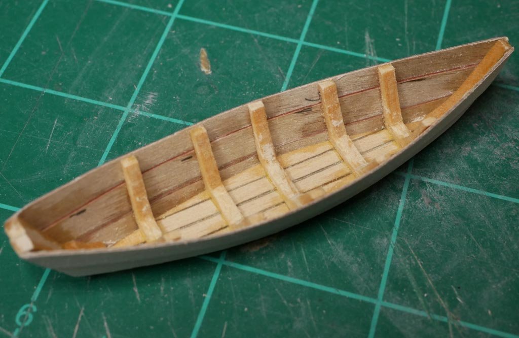
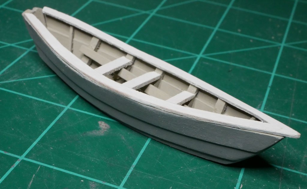
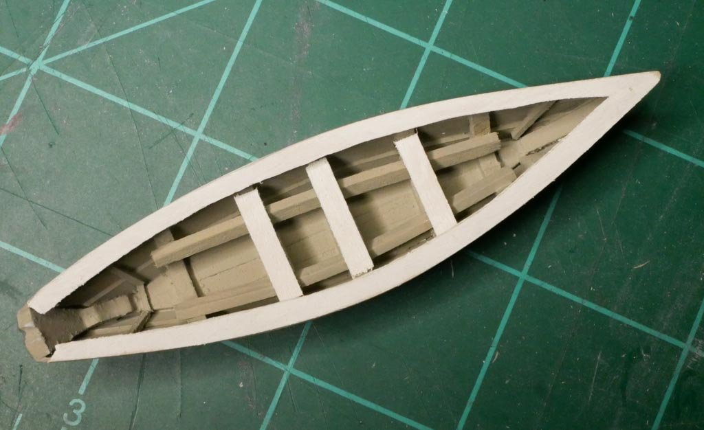
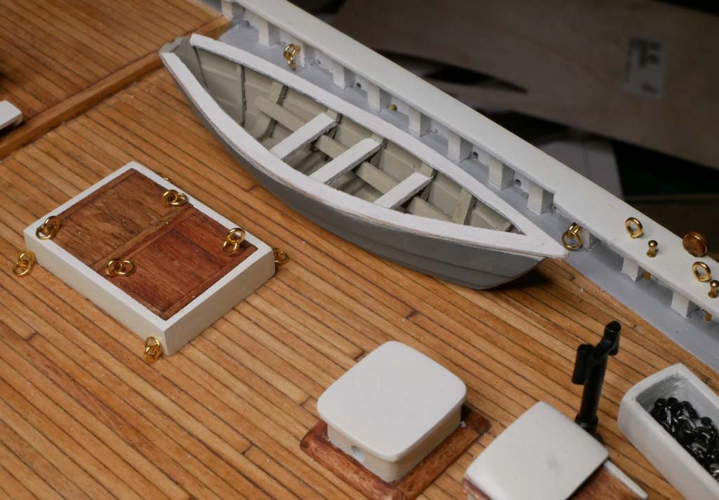
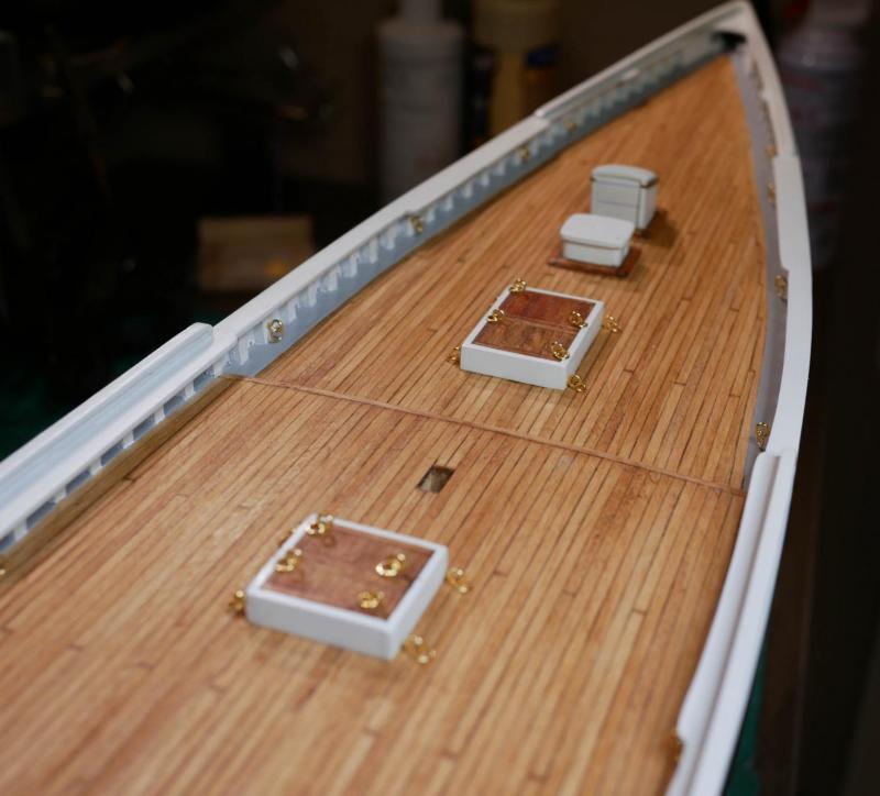
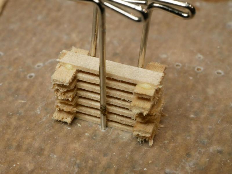
 So, I started in on the dories... The kit provides 1/64" thick laser cut pieces for each of the 8 dories as well as a little jig you can assemble to help make the boats. I'm only planning on using 4 dories on my ship (two stacks of two instead of two stacks of four), so I figure I've got 4 extras to play with in case I mess up. I built the jig and started trying assemble a dory. I had a heck of a time. Even with the jig, I couldn't get the pieces to line up and stay in place while I glued them. It wasn't any fun and I quickly realized that making 4 of these was going to be an unpleasant experience for me. So, I decided to ignore the kit's parts and scratch build a dory. The plans indicate that the kit's dories are simplified - they use a single sheet for each side while the actual dories used three lapped planks. It seems like I could make some frames, attach them to the bottom, then glue on the three planks. Certainly more complicated than the kit's approach, but I think it could be more fun. I started by scanning the plans for the dories into the computer. I used some illustration software to lay out the five frames, the bottom, and the pieces for the bow and stern. I simplified the frames a bit - the plans show the frames are made from two pieces that overlap in the middle. i'm going with one solid piece for each frame. That should be easier to work with and a little more sturdy. I cut out one set of the templates and glued it to a sheet of 3/32" thick basswood. This will make the frames a little thicker than they should be, but I'm worried that if I go thinner they will be too fragile. I used my little Proxxon scroll saw to cut out each of the pieces. Most were pretty easy, but 'frame C' took three tries. Once all the pieces were cut, I scored the bottom piece to simulate individual planks and marked the location of each frame. I glued all the frames on using PVA, and glued the bow and stern in place using CA glue. Even without the planking on the sides, it was already starting to look like a little boat. I used a sheet of 1/64" thick birch that I had laying around for the planking. I cut three strips for each side and installed them from the bottom up. Each plank overlapped the lower one by a little bit as shown on the plans. With pieces this small, I ended up getting glue everywhere, but since the whole thing is getting painted, I'm not too worried about it. Next I added the other details, like the battens at the bow and stern and the thwart support for the seats. Everything was primered and painted, then I installed the seats and a cap rail. The plans call for the dories to be a cream or buff color, but I've seen a few other Bluenose builds that used a greenish-gray, and I liked the way that looked. So I painted the outside with a greenish-gray color. I went with tan for the inside, and painted the seats and cap rail white so they had some contrast. I didn't do a very good job cutting and fitting the cap rail, so that is something I'll definitely have to rethink on the next one, and I'll probably go with thinner material for the next rail. I also used material that was too thick for the seat support rails and seats. I'll need to switch to a much thinner strip next time, and probably mount the seats a little lower (they ended up too close to the cap rail). I also realized at the very end that I had forgotten the cleats. I didn't bother adding the spray rail, thole pins, or oars as this was just a prototype. By the time I got that far, I had proven this approach would work while also making enough little mistakes that I won't end up using this first dory. So no point in 'finishing' it. I dropped my prototype dory on the deck to see if the color choices work, and I'm pretty happy with how they work. The dory stands out, but doesn't look out of place on the deck. I also set the dory on the original plans and verified that the size turned out correct (always a concern when you're scanning in and manipulating plans - one small scaling problem and the size can end up off). After the templates were designed and printed, building this dory took about 3 hours. Since I need four of them (and this one was just a prototype that won't actually get used), that means I've got about 12 hours of dory-building ahead of me. But I found this to be much more fun than building the ones provided by the kit, and I think they will look a better than the kit's dories once I sort out a few issues. And now I've got a three day holiday weekend and my wife will be out of town, so I hope to get all four built in the next few days!
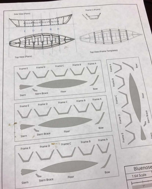

- 245 replies
-
- 9
-

-
- bluenose
- model shipways
- (and 1 more)
-
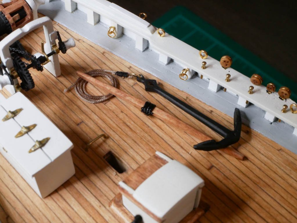
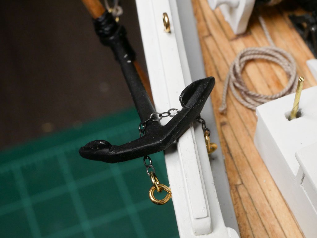
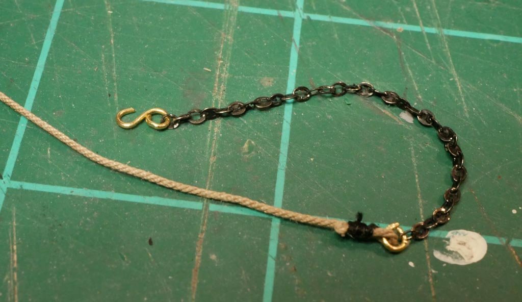
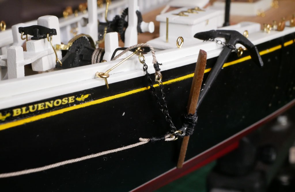
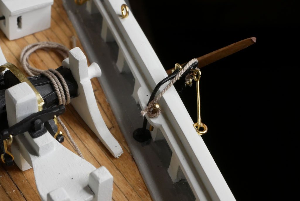
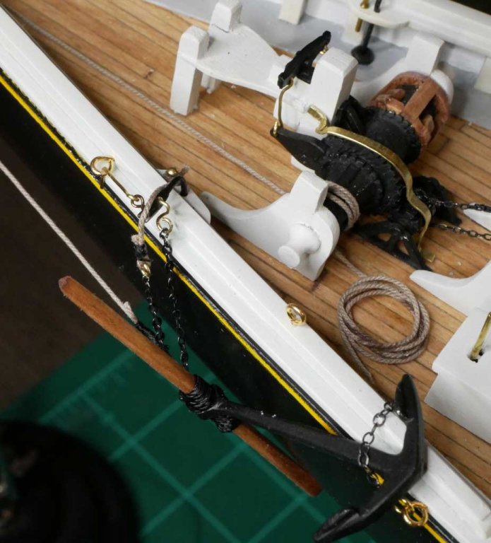
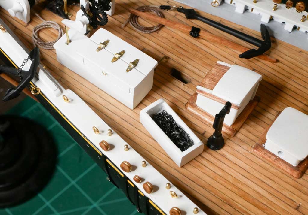
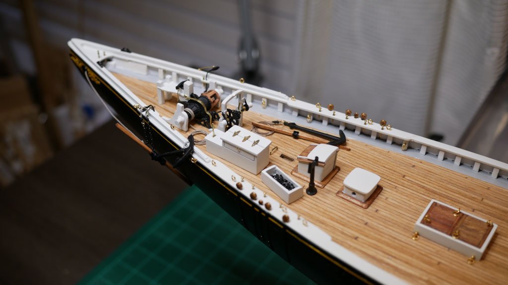
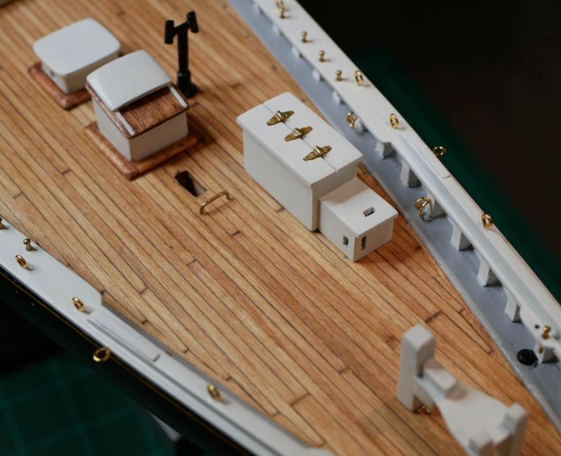
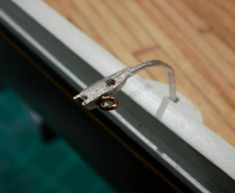
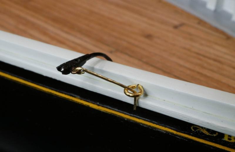
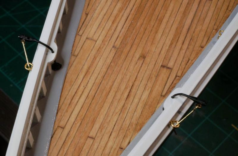
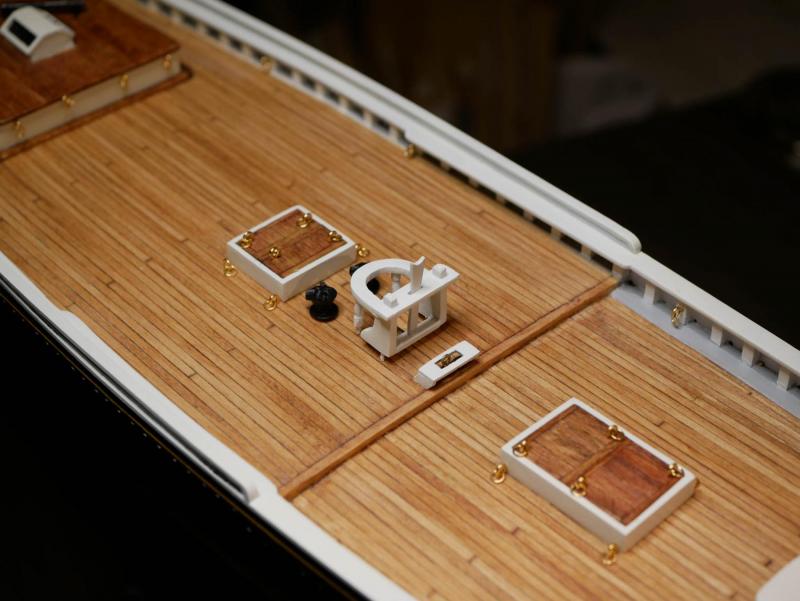
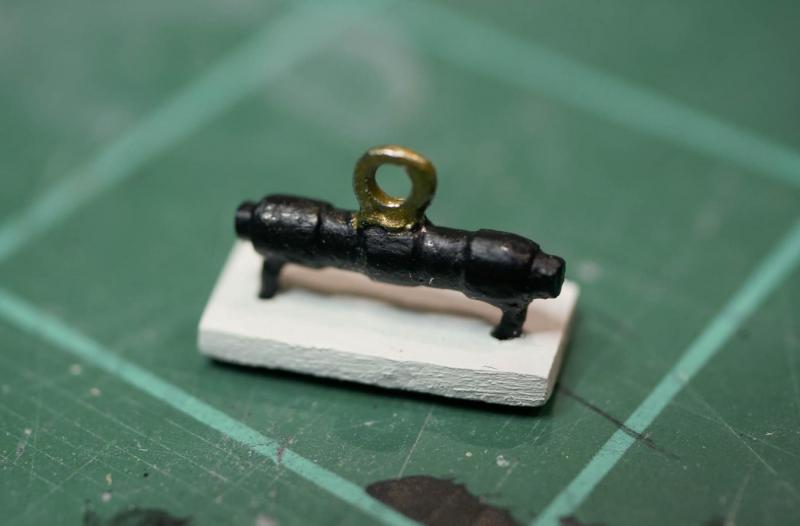
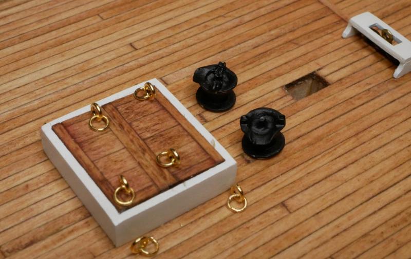
Ok...a very productive weekend! I feel like I'm back in business and making good progress. I rebuilt the chain plates that were lost a couple months ago, and got them installed, then moved on to the anchors. I made some notes back when I built the catheads about how the anchors were going to be hung from the side of the ship. I found a great drawing on page 399 of Chapelle's The American Fishing Schooners 1825-1935. Those notes ended up driving how I set everything up. I might have made some choices that are not actually correct, but the layout I ended up with made sense to me, so I ran with it. (Of course, I know nothing about how ships actually worked...never learned anything about ships until I started building models.) As many do, I left the starboard anchor disassembled and on the deck. I cleaned up the cast metal anchor pieces and painted them black. I made the tapered wood 'bars' from some 3/32" square stock and stained them to match the other wood on my ship. I saw in the plans that sometimes the anchors were attached to chain, other times attached to rope, so I went with rope. I'm using some of the rope from Syren Ship Model Company that I ordered a while back (I ordered a full set of replacement line for all the stuff provided in the kit). Even though this anchor will be left disassembled on the deck, I added a little black rope to the 'bar' so it wouldn't look quite so bland. A little bit of extra rope was left coiled up. The port side will have the anchor hung from the rail. I started by using some chain to secure the end of the anchor to the anchor pad. Next, I made a chain/rope combination like I saw in the drawing I found. This has a hook one end of the chain, with the other end of the chain secured to some rope. The hook will go into the cathead. The chain will loop through the ring on the anchor, then swing back up so the rope can go through the sheave on the cathead. The rope will then be tied off on the belaying pin next to the cathead. This was hooked in place, the used to secure the anchor to the cathead. I'll add a rope coil to that belaying pin later when I'm adding final details. Obviously these little catheads don't have actual sheaves, so I just ran the rope over the end of the cathead. I ran the anchor's rope through the hawse pipe, wrapped it around the winch, and left a little extra rope coiled on the deck. While I was at it, I went ahead and installed the chain box, and filled with some left over chain. So, I'm now done with chain plates and anchors. All I have left before masts are the dories, which should be fun - kind of like little mini-builds in themselves. I'm excited to back at it, and looking forward to getting those dories going during the upcoming three-day weekend!
- 245 replies
-
- 15
-
-
- bluenose
- model shipways
- (and 1 more)
-
Thanks for the encouragement everyone! I got the remaining 10 chain plates re-made today, and hope to get them installed over the next few days. I think I can finish this build before the end of the year, then on to whatever is next. I was chatting with my wife the other day, and explained that I'd love to build the 18th Century Longboat next (kit already in the closet), followed by the Syren (which would be my first ship with guns), then maybe the Constitution (which she loved - an excuse for a trip to the east coast), then maybe the Victory (also something she loved, an excuse for a trip to the UK). After that...probably scratch builds? Is it bad that I'm only 2/3 done with my 2nd build and I've got the next 5-10 years of ship builds planned out?
- 245 replies
-
- 5
-
-
- bluenose
- model shipways
- (and 1 more)
-
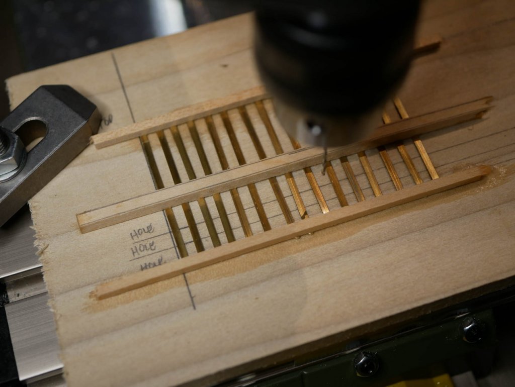
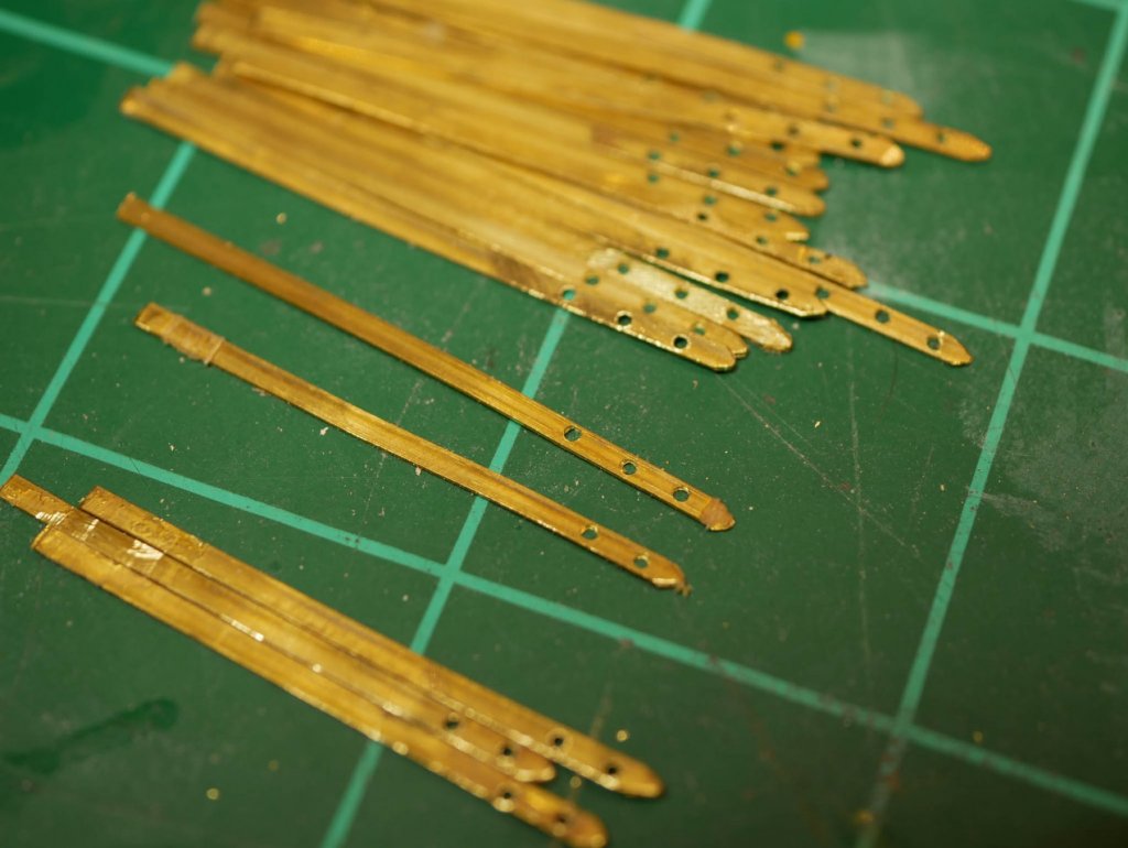
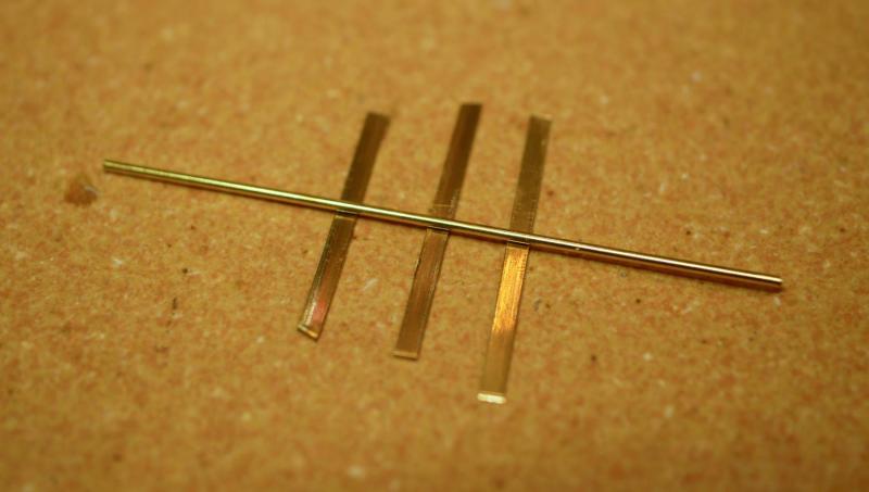
Well, it has been a long time. I wish I could say I've made tons of progress, but it has been a crazy few months. Back in January, I was on a roll. After finishing the winch assembly, I jumped right into chain plates. The Bluenose has 20 chain plates, so I decided to prepare them all at once. I cut strips of brass and made a jig to help my get the holes drilled on my little Proxxon drill press. This worked really well, and very quickly I had 20 brass strips with decent looking holes and filed tips. These were then painted black, and I started the process of installing them. This required drilling some holes in the main rail and creating a 'slot', being careful to make sure I stayed on the outside of the bulwarks. I attached the deadeyes (after staining them) using wire. I got through all 10 on the quarter deck. This all happened within a few days of my last post. Before starting in on the chain plates for the fore deck, I decided to take a week off. Then disaster struck. We have a service that comes and cleans every other week. For years, they have cleaned around my work bench. This time, they decided to actually clean my work bench. The remaining 10 chain plates were lost. I'm guessing they got 'wiped' onto the floor and vacuumed up. This was incredibly demotivating, and I decided to take another week or two off. Fast forward a few weeks, and we were starting a remodel of our house. This included all new floors (I've wanted to replace the carpet in my office/ship-building-room for a while so I stop losing tiny pieces in the carpet). Since they needed to replace all the floors, I had to pack up my entire workbench for over a month. The ship was carefully wrapped up to protect it from dust (our entire house was covered in dust for weeks), and stored in one of the 2 rooms that wasn't being touched - a bathroom. It was a little unnerving to have my ship sitting in a bathtub for weeks, but it survived. I decided to hold off on starting the build back up until ALL the remodeling was done in order to avoid issues with dust. The whole process took about 2 months. So finally, today, I have everything set back up. The workbench is unpacked. Power tools (mill, drill press, scroll saw) are back in my make-shift shop (a walk in closet in my office). I'm ready to dive back in and re-make those 10 chain plates. During this break, I crossed the 1 year mark on my build. I thought I'd be further along by now, but I've kept detailed notes on my progress and I see where the time went. Since future builders of the Bluenose may stumble across this build log, here's how the last year went: Build started April 1, 2016. Framing (keel, rabbet, bulkheads, fairing, stern blocks) - 16 days. Planking the lower hull (up to the deck) - 28 days. Planking the bulwarks, scrapers, transom - 11 days. Planking the deck - 24 days. Cleaning up the hull (hawse pipes, mooring chocks, etc) - 6 days. Painting the hull - 68 days. Rails (main rail, buffalo rail, monkey board) - 34 days. Hull details (rudder, name plates, scroll work) - 41 days. Deck structures (cabins, hatches, companionways, etc) - 28 days. Aft deck details - 4 days Fore deck details - 4 days Machinery (engine box, countershaft, windlass, hoisting, etc) - 31 days The first big stall came with painting, which took over 2 months, mostly driven by waiting a week or so between coats. The second big stall has been my chain plate disaster/remodel. So, here I am, 1 year into this build, ready to dive back in. I have just a few things to knock out (chain plates, anchors, dories) before I start building the masts, which obviously leads to rigging. My best guess right now is that I have 8-12 months left. I'm excited to finally be able to work on the ship again, and I look forward to being able to post an actual update with progress!

- 245 replies
-
- 12
-
-
- bluenose
- model shipways
- (and 1 more)
-
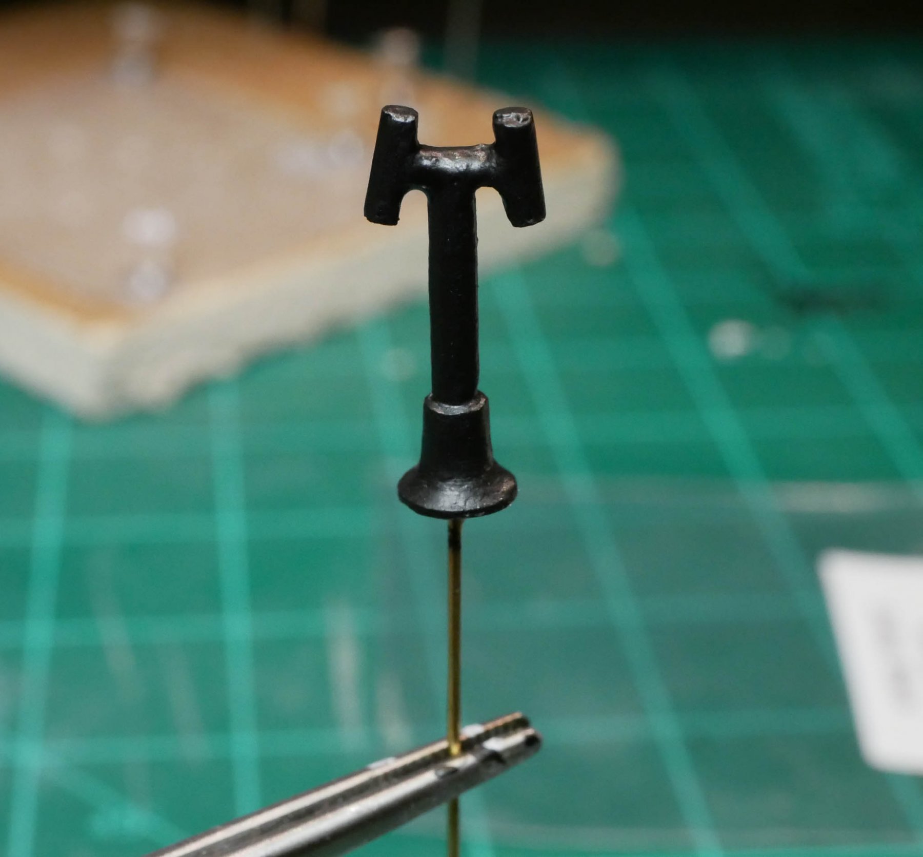
I do all the painting I can with an airbrush (I'm horrible at hand painting), and I've run into the same problem. I use the tape method you described many times. Another technique I use quite a bit is to drill a small hole in the bottom of the piece and glue in some thin brass rod. I leave the rod long, and use that to hold the piece during painting. Once painting is done, I trim the rod down. Often I leave a little bit of the rod and use it as a 'post' to help secure the piece more firmly on the ship. I also have a few small pieces (4x6 inches) of that generic white acoustic ceiling tile you find in a lot of offices - it makes a great board to stick pieces into during painting. (The brass rod I glue onto the piece kinda acts like a push-pin.). I bought one ceiling tile at a hardware store several years ago for under $5 and have just been cutting small pieces off as needed. I normally flip the ceiling tile over and use the unfinished 'back', and lay some wax paper over it.


-
I've got a dedicated drawer in my workbench for scraps. I probably toss too much stuff in there, but it comes in handy. I also toss any misc. jigs I make from wood in there when I'm done. I've been able to repurpose a number of them. I've realized that I reach for wood from the scrap drawer before I reach for the kit's material, and I've been finding that I often have a little piece that will work better than the kit provides (especially for all the little buildings on the deck!) Unfortunately my drawer is a wire mesh material, so I'm constantly fighting the tiny pieces of brass that slips through the bottom of the drawer.
-
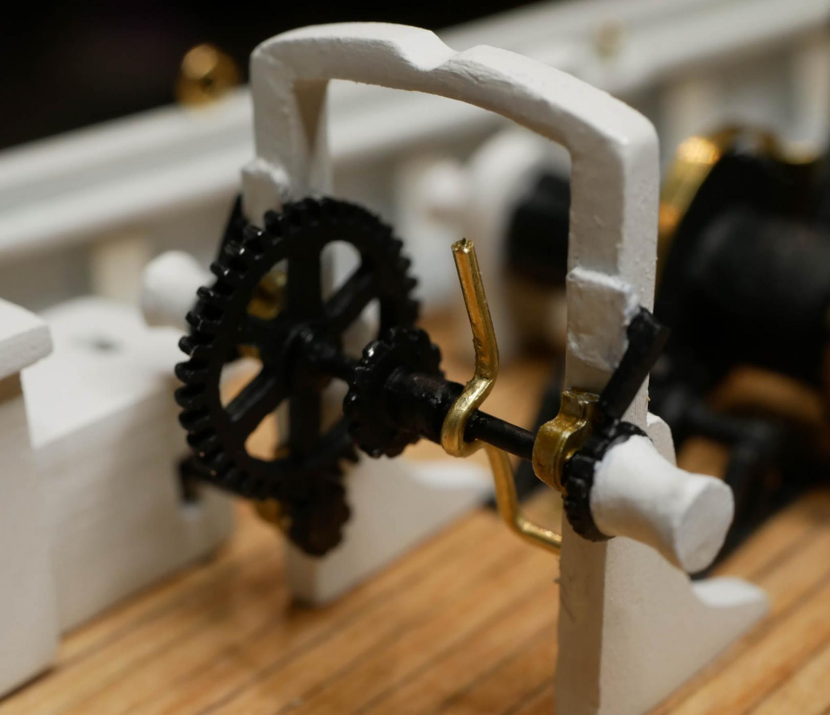
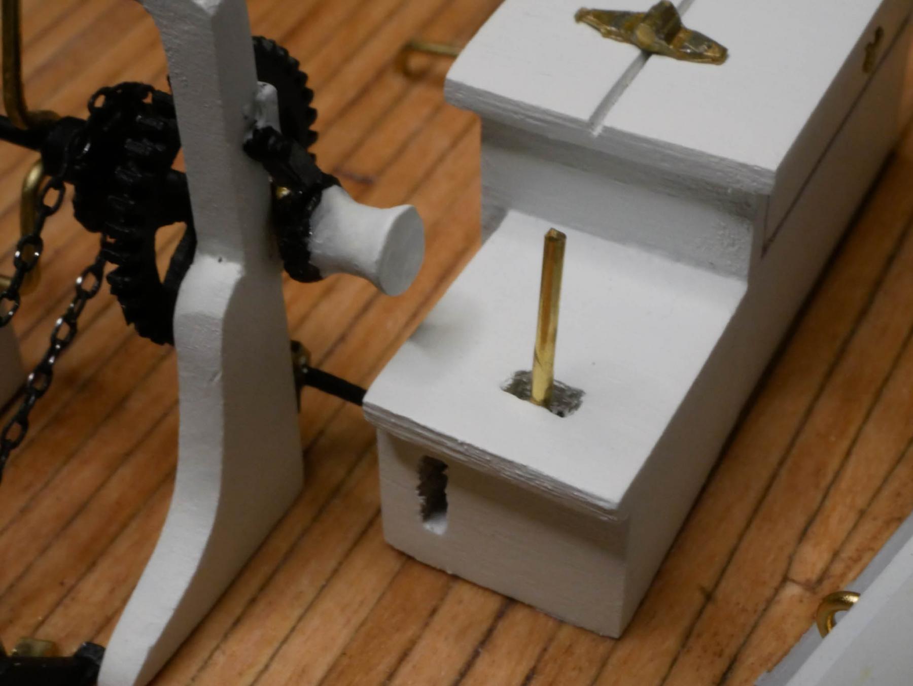
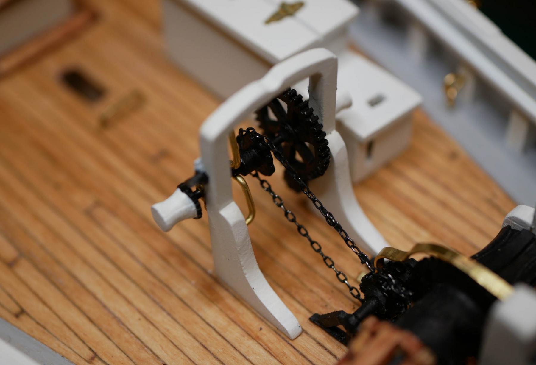
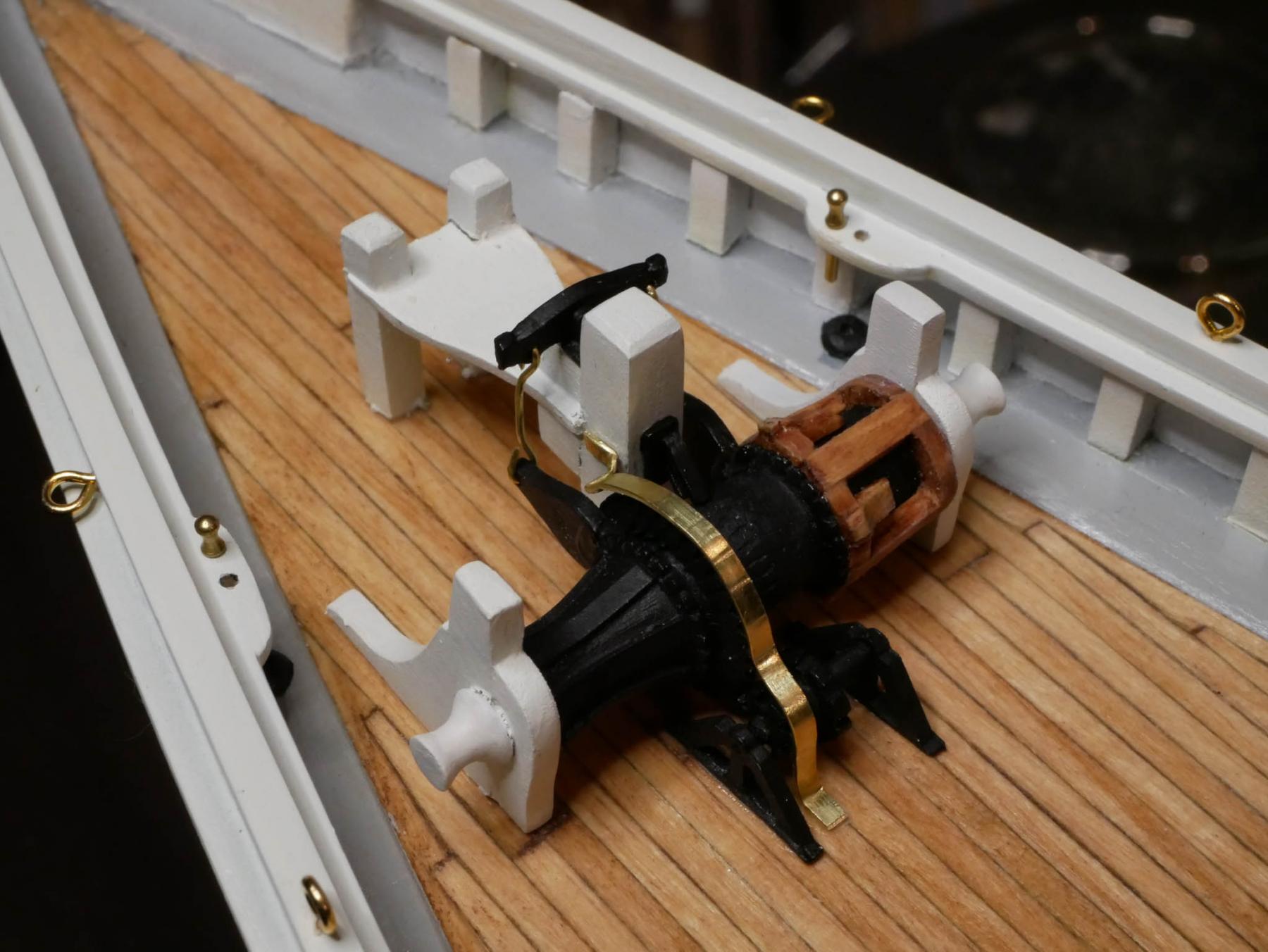
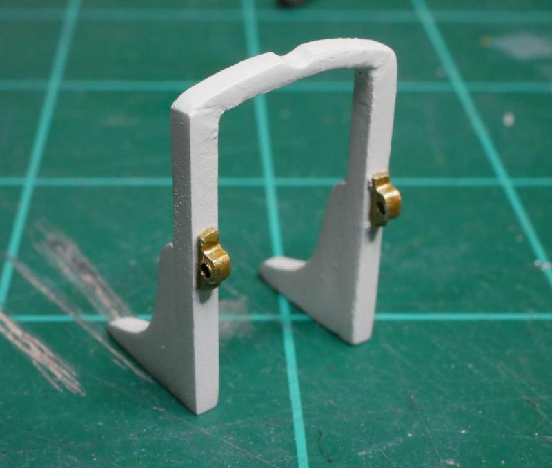
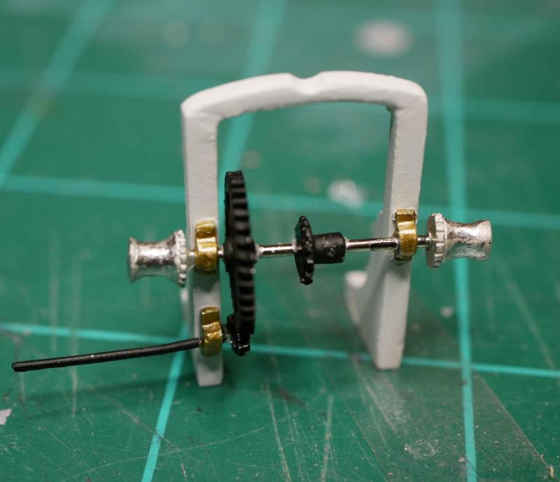
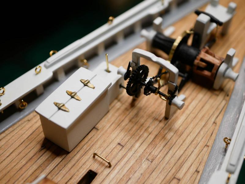
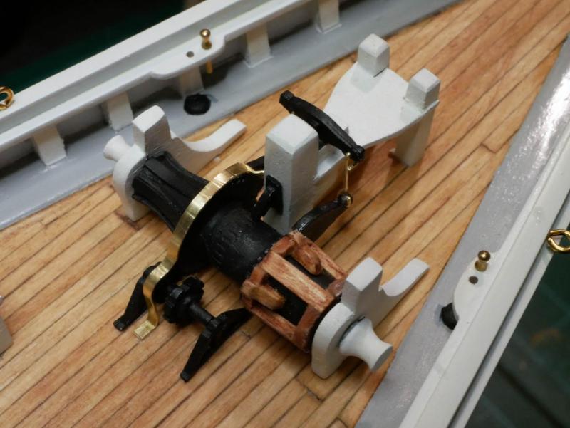
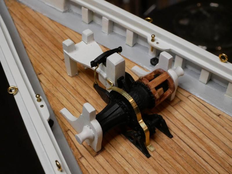
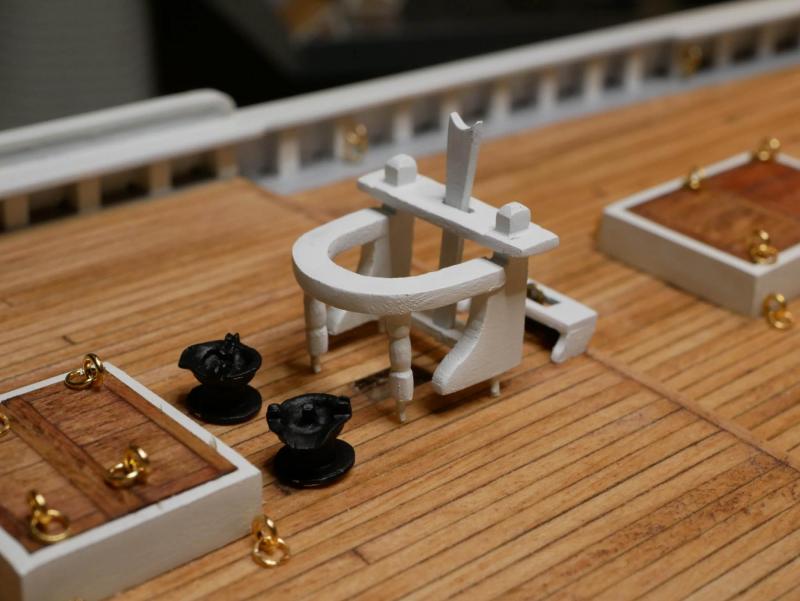
The winch machinery is complete, which finishes up all the stuff that is permanently mounted to the deck. The jumbo jib boom crutch was built from the kit's laser cut parts and some wood strips. I ended up having to add some CA glue to the joints at the top - they were flexing too much with just PVA glue alone and I was concerned they would break during painting. Some wood filler was used to clean up the joints between the posts and the knees. As I did with the windlass, I decided to break with historical accuracy a bit on the colors and finishes. I'm making the mounting brackets and handles brass so they stand out a bit, and I'm going to paint the end caps on either end of the winch's main bar white to match the ones on the windlass. I think all of these would have likely been black metal on the ship, but making them look a little different will make the details stand out more on the model. The kit ships most of the parts for the winch already assembled on a metal rod. I completely disassembled these so I could paint things separately. I started by gluing the mounting brackets in place. I used a scrap piece of brass rod to ensure they were properly aligned during installation. Then I installed the winch's bar. I reattached one of the end caps, then slid the bar through one of the brackets. Next I slid the larger and smaller gears on, then slid the bar through the other mounting bracket, trimmed it to the right length, and installed the other end cap. Finally I glued on the clutch assembly below the main gear. The winch's metal rod was left unpainted during installation since sliding on those pieces would have stripped the paint anyway. With everything in place, I finished up painting and installed the pawls and control bar. I kept the bar simple. The plans show multiple pieces, but I made it out of one piece of brass rod that was bent around the rod. The end caps were painted white except for their gears, which were painted black so they would stand out. The mounting plates for the pawls were painted white simply because I felt they stood out too much when painted black like the pawls themselves. The whole thing was then glued to the deck. The control bar was added to the top of the engine box. Again I used a brass rod so it would stand out. I didn't plan ahead well enough, and there was nothing but empty space inside that hole on the engine box, so I didn't have anything to seat the bar into. Instead I simply glued the bar to the side of the engine box hole. The final step was to connect the winch to the counter shaft assembly. The plans suggest doing this with some thread, but I wanted to use an actual chain. My wife owns a jewelry business, so she was kind enough to give me a few inches of very tiny scrap chain. I felt a little bad because the chain is actual silver and I immediately dunked it in black paint. I'll consider it a sacrifice to the model ship building gods. Installing the chain was a mess. I'm not thrilled with the results. If I had it to do over again, I would have built the chain back when I made the windlass, and glued the chain around the counter shaft's gear before it was mounted to the deck. Trying to get the chain wrapped around that properly, and getting glue applied, was a real challenge once everything was fixed on the deck. Overall, I'm content with this batch of work, but I don't think it turned out as well as some of the the other pieces on the deck. This completes my 'machinery' phase, and finishes up the stuff that is permanently mounted to the deck. I still need to do the anchors and dories, but since those are 'portable' on the actual ship I'm treating them as a separate project. First I plan to make and install the chain plates since I think putting those in after the dories are installed will be trickier.


- 245 replies
-
- 7
-
-
- bluenose
- model shipways
- (and 1 more)
-
Welcome back! I'm glad to see another Model Shipways Bluenose log come back to life! I've been going through some withdrawal since Jerry finished his. I noticed you're also building the Fair American, and you have the 18th Century Longboat in the wings. I promise I didn't intentionally copy you, but I'm about halfway done with my Bluenose, I've got the Fair American kit on the shelf, and I received the 18th Century Longboat kit for Christmas. So, I'll be pretty glued to your build logs for while!
-
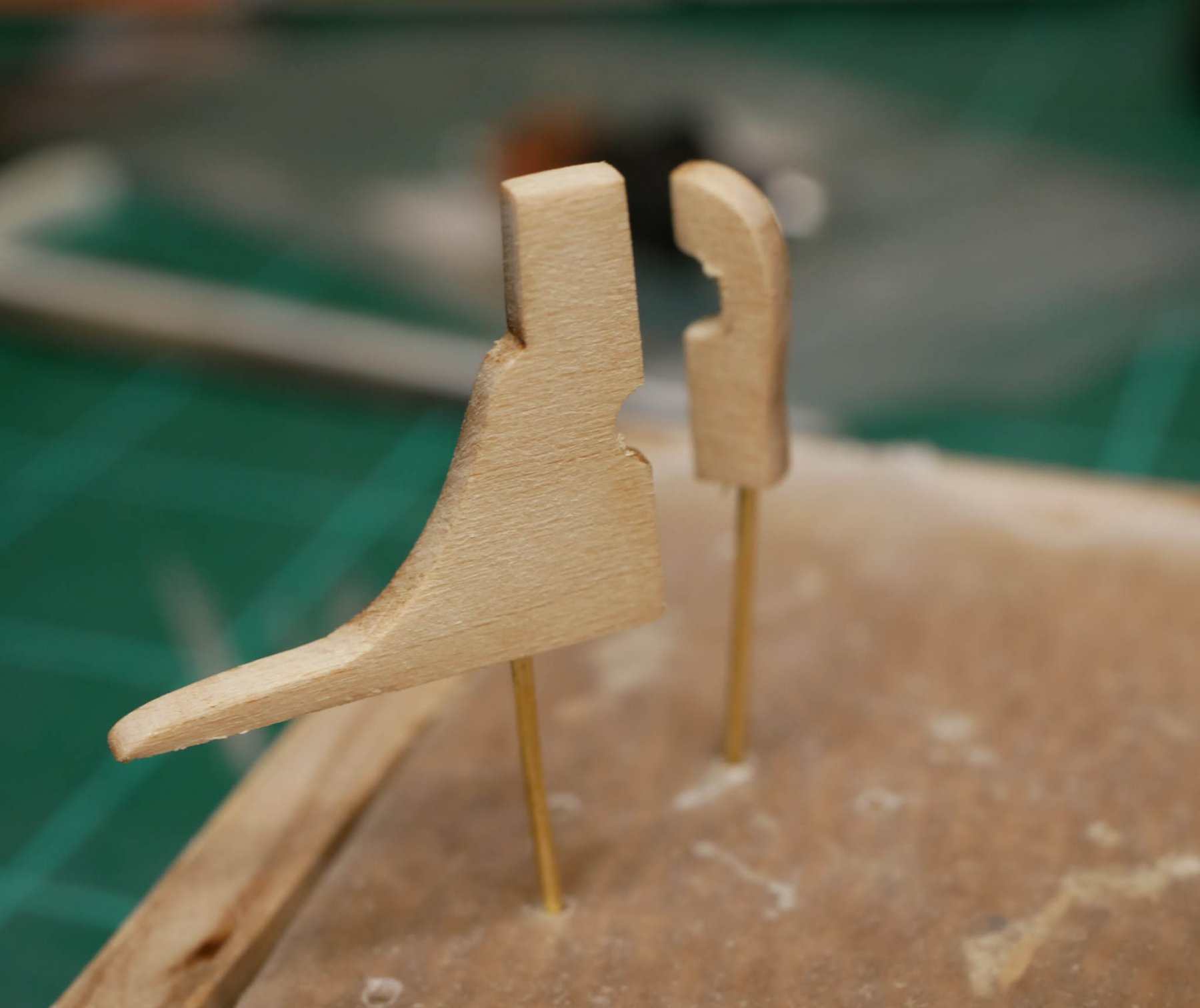
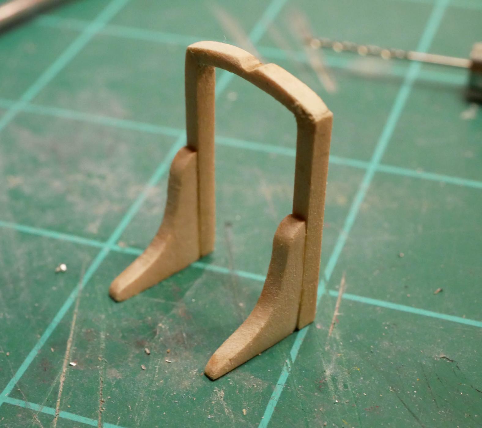
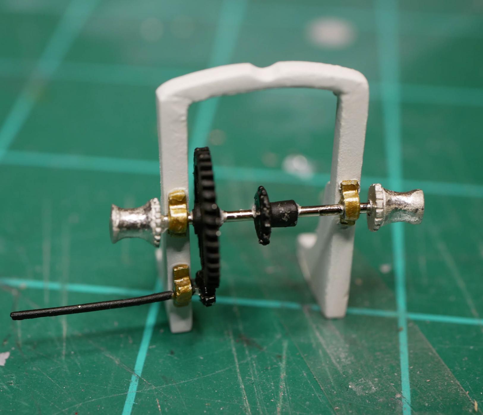
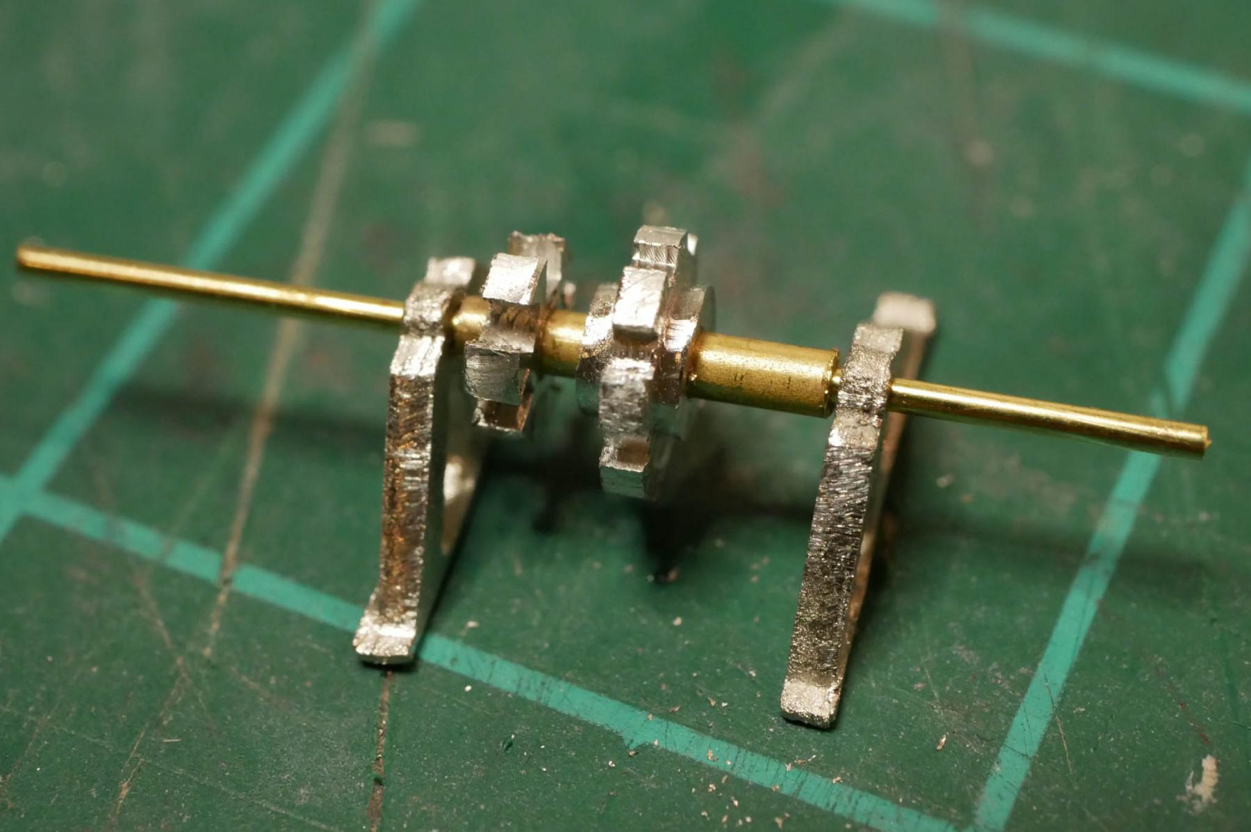
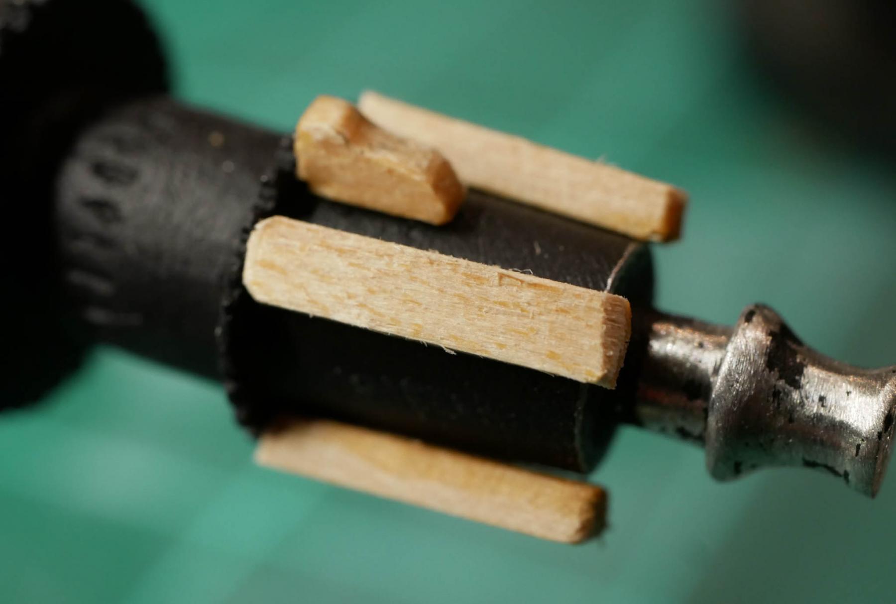
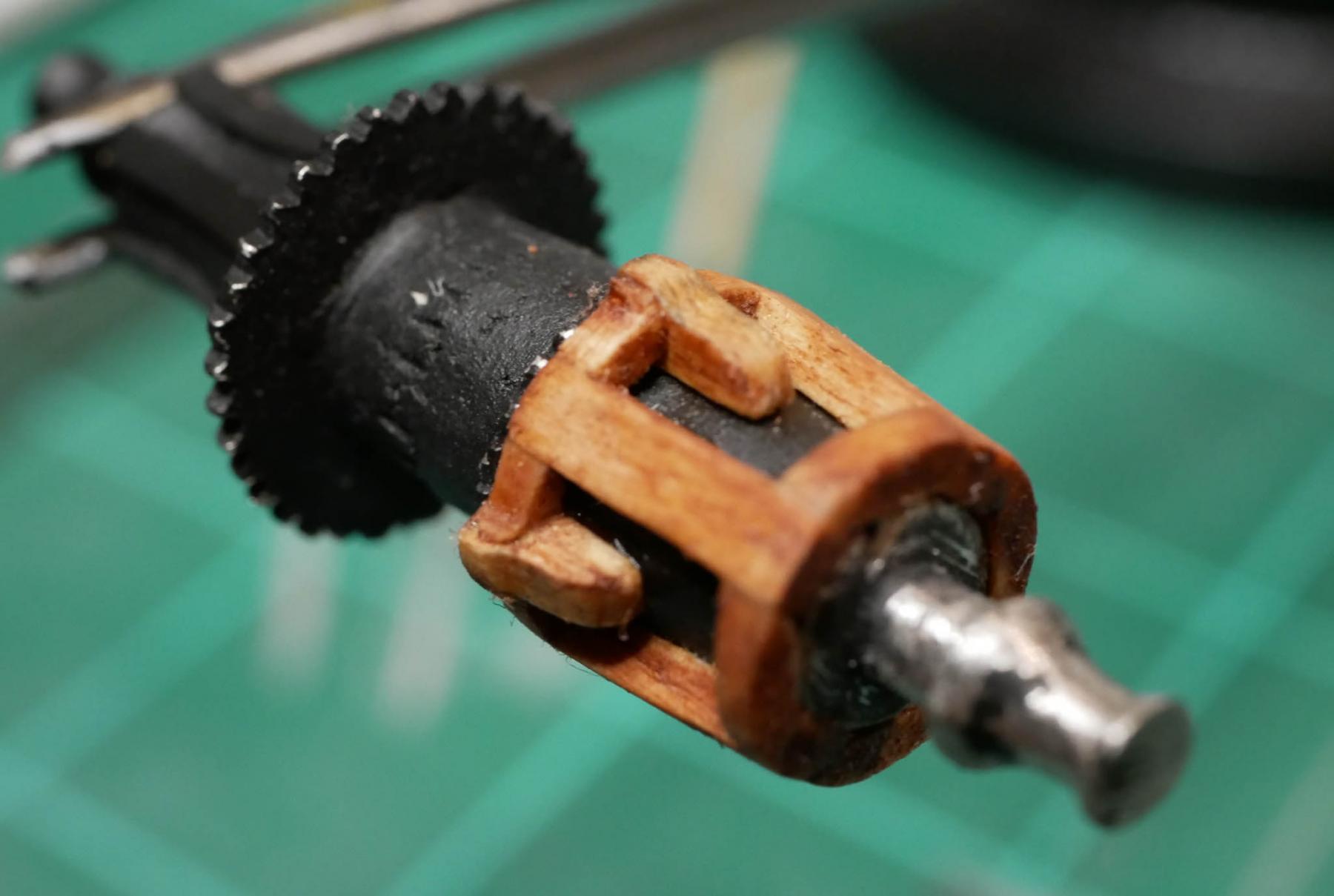
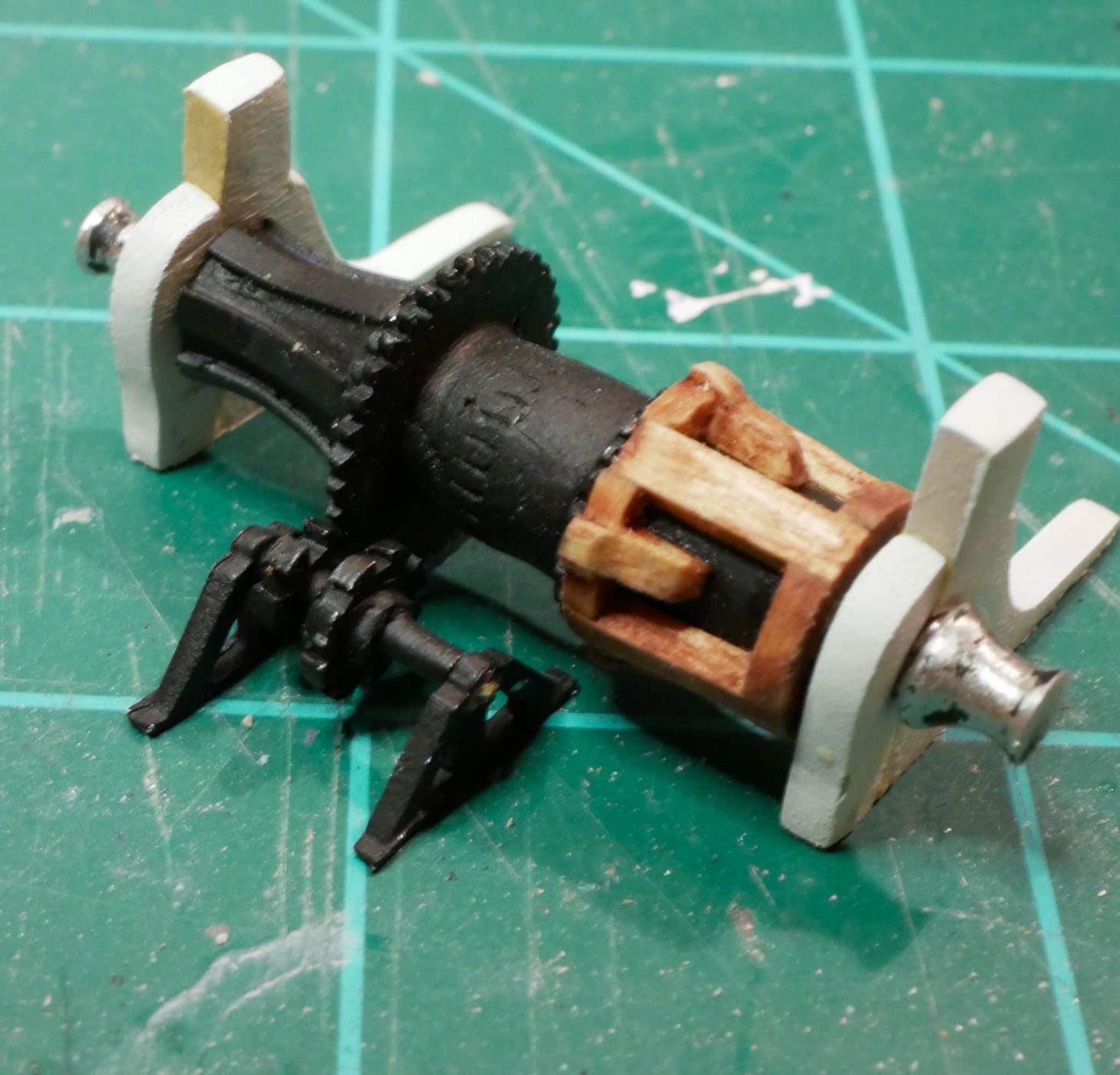
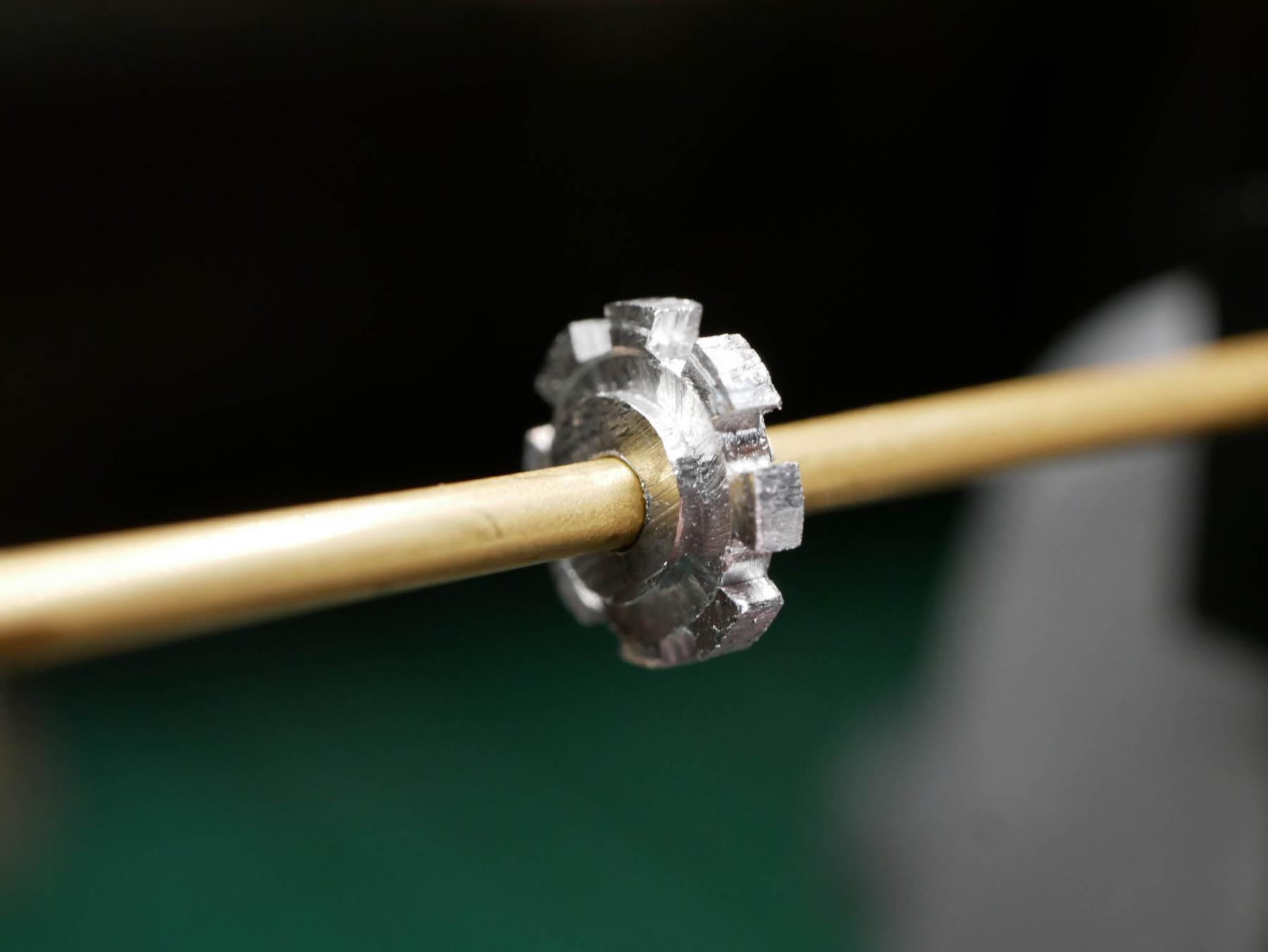
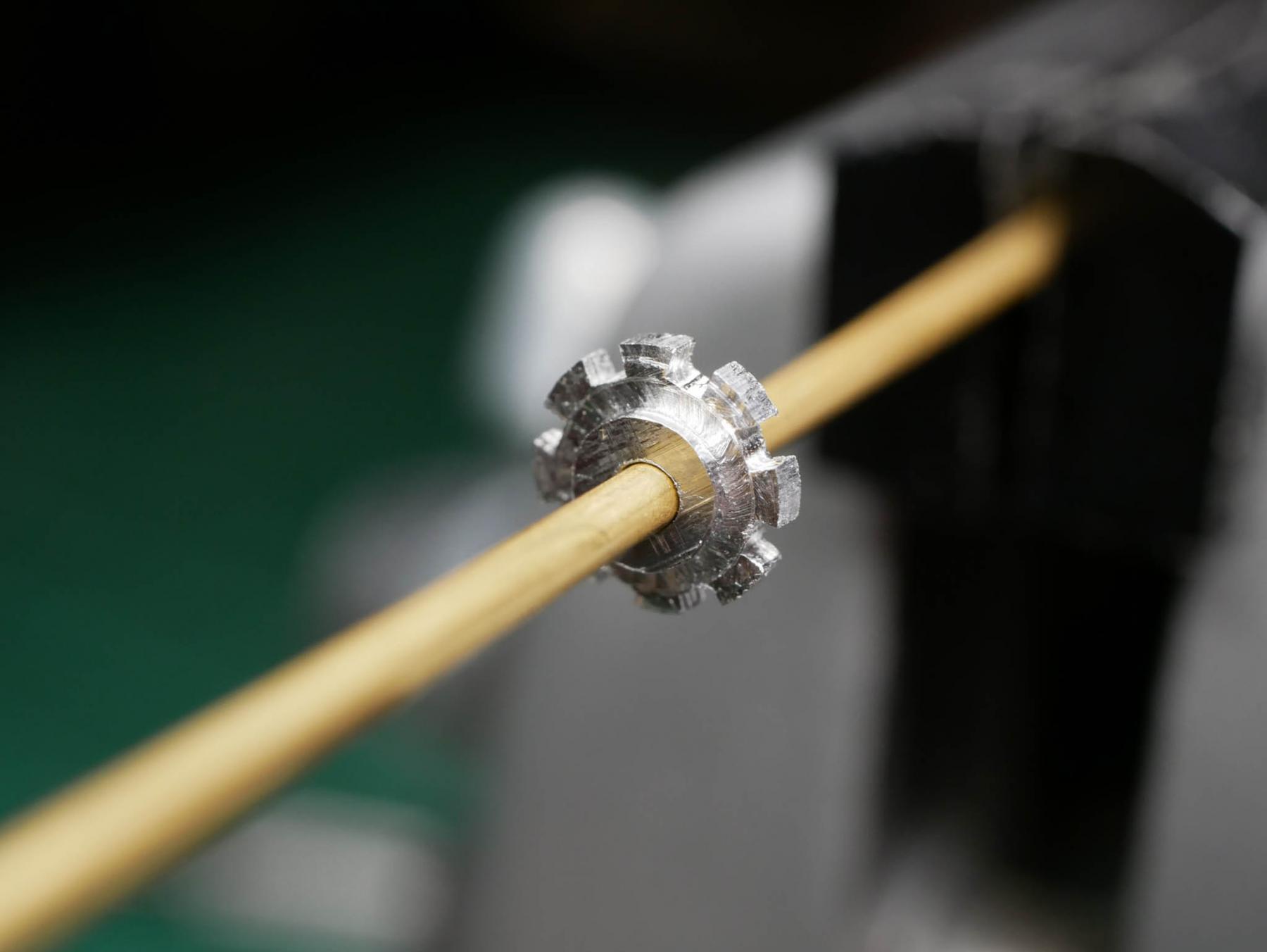
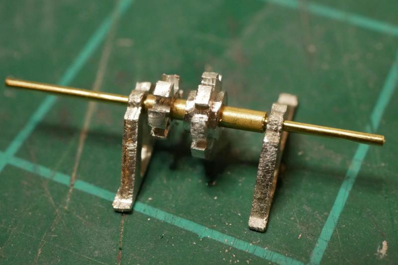
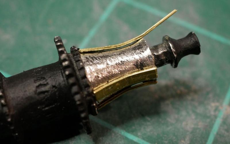
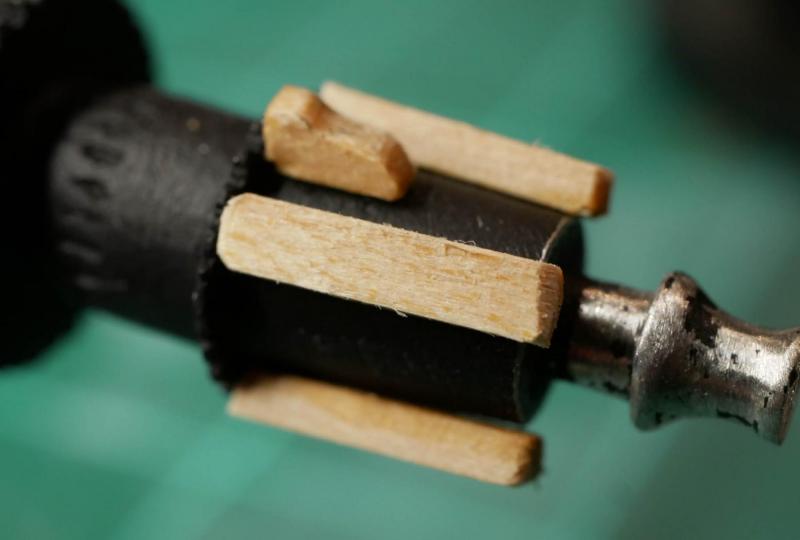
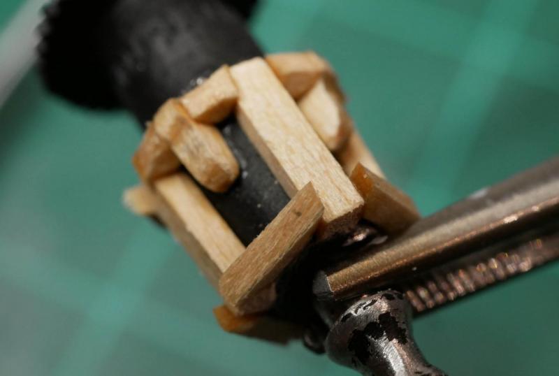
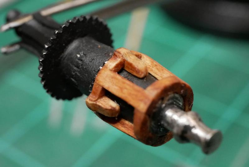
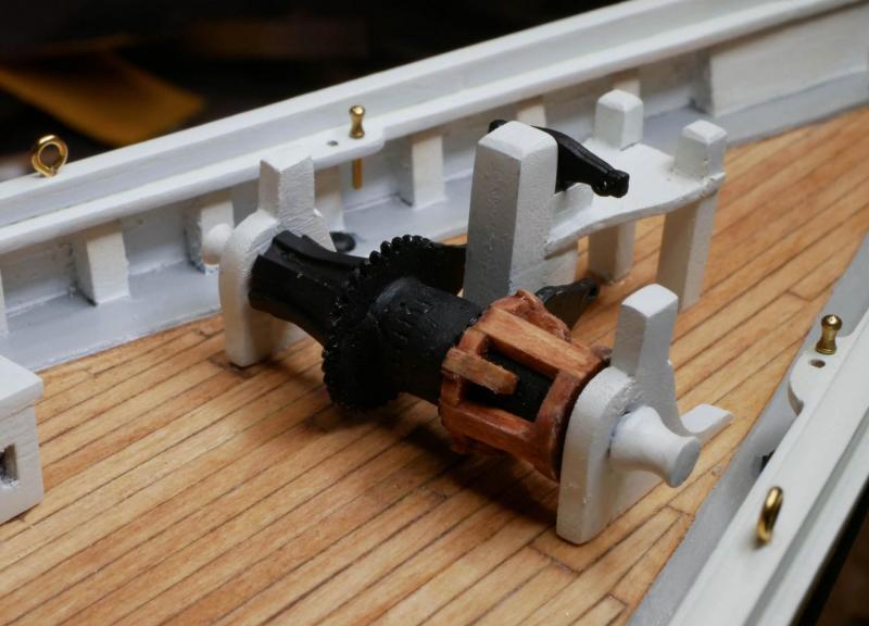
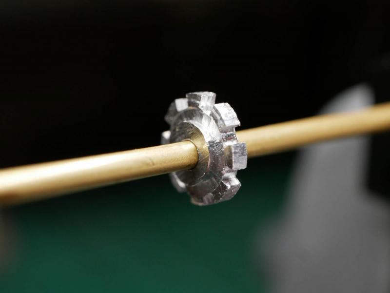
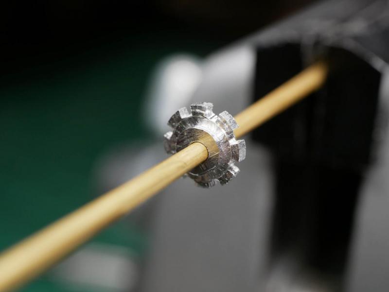
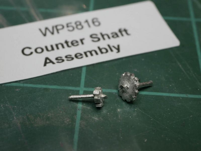
Despite the holidays being a surprisingly busy time, I've been able to get a good bit of work done. As mentioned in my previous post, I made my own gears for the counter shaft assembly by milling down a 1/4" aluminum rod. This was completely unnecessary, as I could have just drilled some holes through the kit-provided gears to overcome the broken piece, but I really wanted to play with the new mill. In the end all my work won't really be visible, but it was fun to do. With the gears made, I was able to assemble the counter shaft. Since the holes in my gears were larger than those in the stands (I couldn't find a smaller bit that would drill into the aluminum), I mounted the gears onto a brass tube, then slide that tube over some thin brass rod that fits the holes in the stands. With that out of the way, I finished up the chain box. The plans don't show this on the deck, but there is a detailed drawing of the box included in the plans with a note that it goes 'just aft of the engine box.' I went ahead and built it, but I'll wait to glue it down until I start running the chain later in the build. The exact positioning of this will depend on how I lay the chain. Now I come to the windlass. When I first started looking at build logs for the Bluenose, even before I bought the kit, the windlass was intimidating. It was actually pretty easy...it just has a lot of little pieces. I started by cleaning up the cast metal barrel provided with the kit. I painted the whole barrel black (I'll scrape off paint as necessary to glue things on). I know that much of the windlass was actually wood, but I've never liked the look of wood-colored paint, so I'm just going with black. One end of the barrel got some brass strips glued on. This whole end will be painted black. The other end requires more work. After staring at the plans for a while, and reviewing other build logs, I still wasn't sure exactly how this end was constructed. Finally I found a photo on the Nova Scotia Archives website that had a good view of the windlass. I based my approach off that, but a little simplified since I'm limited by what I can do at this scale. I glued on some 3/32" square strips, and added some shaped pieces to make the whelps. Then I filled in the spaces at either end with tiny pieces of wood. This was a lot of trial-and-error. I didn't try to get the pieces to fit perfectly flush - I'll sand everything down later. Once all the wood was firmly in place, I added some wood filler in the joints and sanded everything down. Then I stained the wood to match the other wood on my above-deck structures. The stands were made from the provided laser-cut pieces and glued together. This let me finish up the counter shaft assembly and get the gears positioned. The brake beam was glued onto the bowsprit bits, and the two quadrants were glued onto the barrel. With all this in place, I positioned the windlass and glued it onto the deck. The pawl as installed, and I added the brass rods from the brake beam to the quadrants. The counter shaft assembly was then glued in place. Finally, I noticed the detailed drawings in the plans referenced a metal shield over the gears. I shaped this from some brass strip and glued it in place over the gears. Since I'm leaving lots of natural brass in other places on the ship, I decided to leave this piece unpainted. I'm sure it was black on the ship, but I like the contrast that a bit of brass gives here. I don't want all the machinery to look like a big blob of black painted stuff. So I'm done with the windlass. It only took about a day (aside from the counter shaft, which took a couple weeks due to the custom gears). Next up will be the winch machinery.


- 245 replies
-
- 11
-
-
- bluenose
- model shipways
- (and 1 more)
-
Thanks Dave B and Jon! Making my own gear was a little bit of overkill, but it was fun to get a 'real' project to try out on my new mill. Now that the holiday is over, I'm hoping to get a chance to tackle the smaller gear in the next day or two, which should be a little more challenging!
- 245 replies
-
- 2
-
-
- bluenose
- model shipways
- (and 1 more)
-
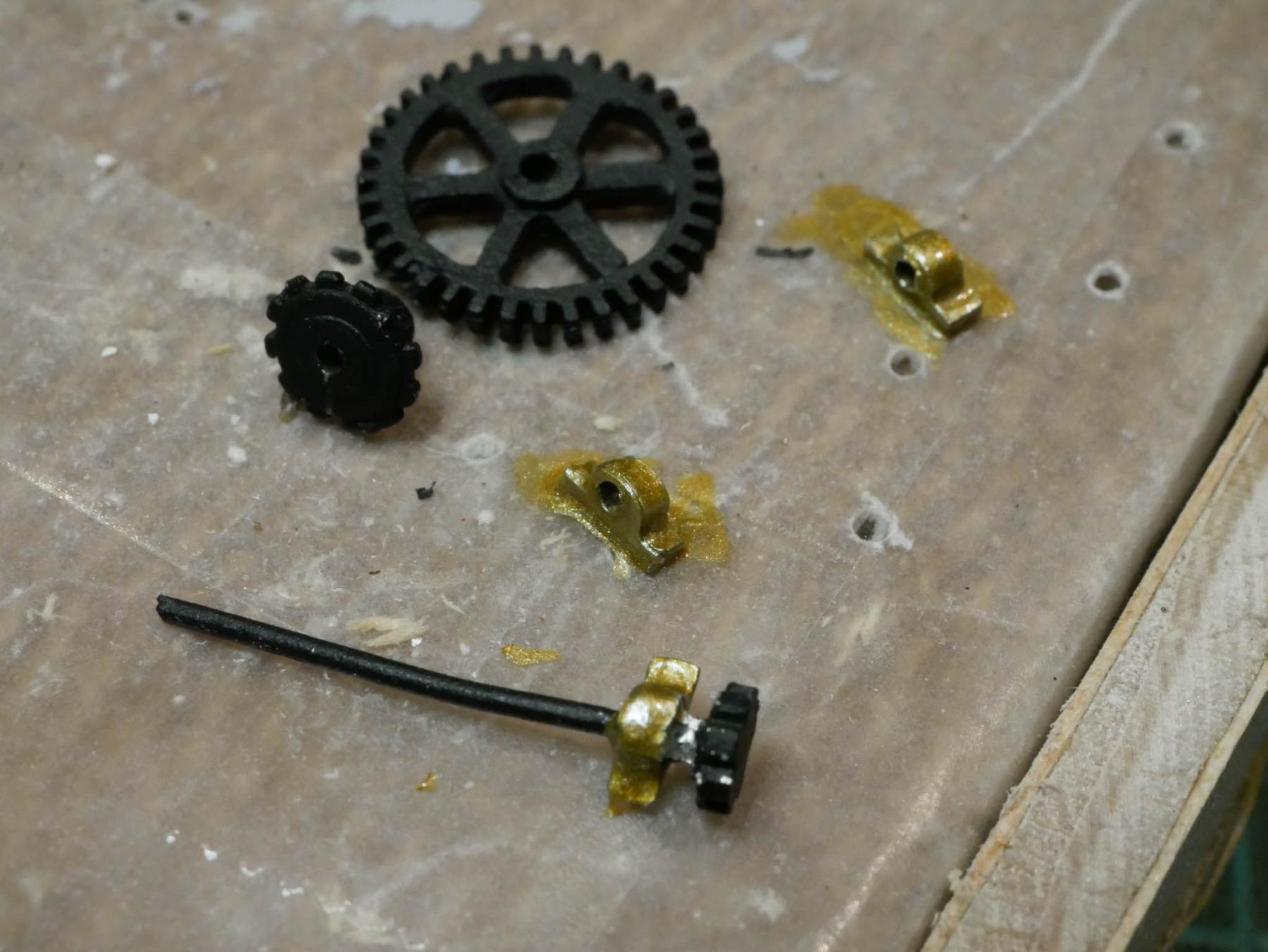
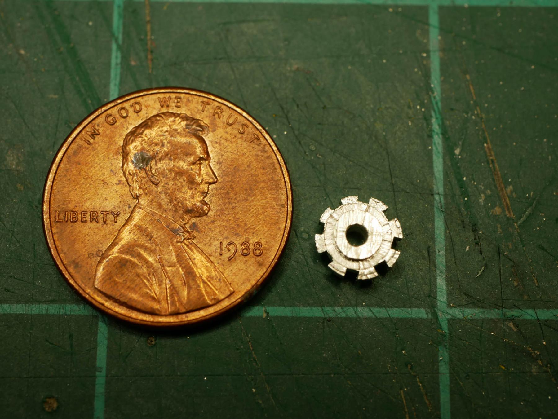
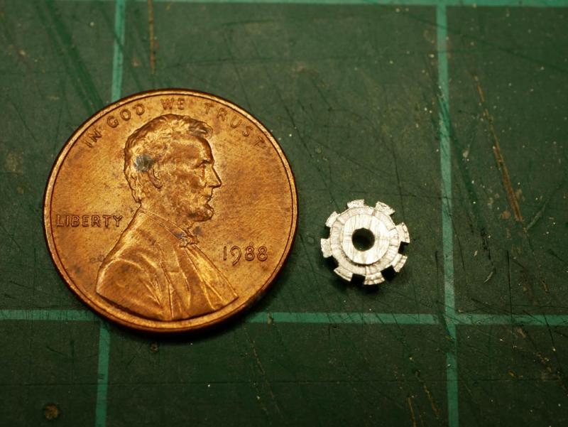
This last week has been spent playing around with new toys to try and overcome a problem. I recently started work on the windlass and machinery. The first piece I worked on was the countershaft assembly. My very first step was to clean up the metal casting provided by the kit. This piece is basically a rod with two gears on it. Naturally, I broke this piece while working with it. I snapped the rod. I cut the gears loose from the rod, and I am holding on to those as a safety net - I can always drill holes through them and slide them onto my own brass rod. But...I just got a new Proxxon MF70 mill and I've been looking for things to try and make with it. I decided to take a stab at making replacement gears using the mill. The larger gear is 1/4" in diameter, so I started with a 1/4" diameter aluminum rod. I used a 3mm bit on the mill to do most of the work, and a 1mm bit to cut the 'teeth'. I used my drill press to drill a hole through the center. The rotary vise for the Proxxon made cutting the teeth pretty easy once I figured out the # of degrees between cuts. It took 4 tries, mostly because I was still learning how to use the mill, but I did manage to make a usable piece. It isn't perfect, and the teeth are different than the kit-provided piece, but I think it actually looks cleaner and more precise than the cast piece. Once this is painted, I think it will look fine! I was very happy with the level of precision on the Proxxon. It cut through the aluminum easily. I'm sure it might have a tougher time if I were doing something larger (and the Proxxon is very much for model work, not larger-scale machining like you'd do with a bigger mill). All the milling was done manually (turning dials) since I'm still waiting on the motor mounts for my CNC conversion. (Although I have gotten all the electronics working and the control software halfway written). Anyway, I haven't actually made any progress on the ship, but I've managed to make a gear, and I've very happy with that accomplishment for the week!
- 245 replies
-
- 7
-
-
- bluenose
- model shipways
- (and 1 more)
-
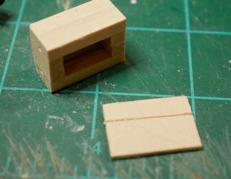
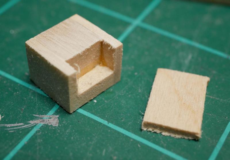
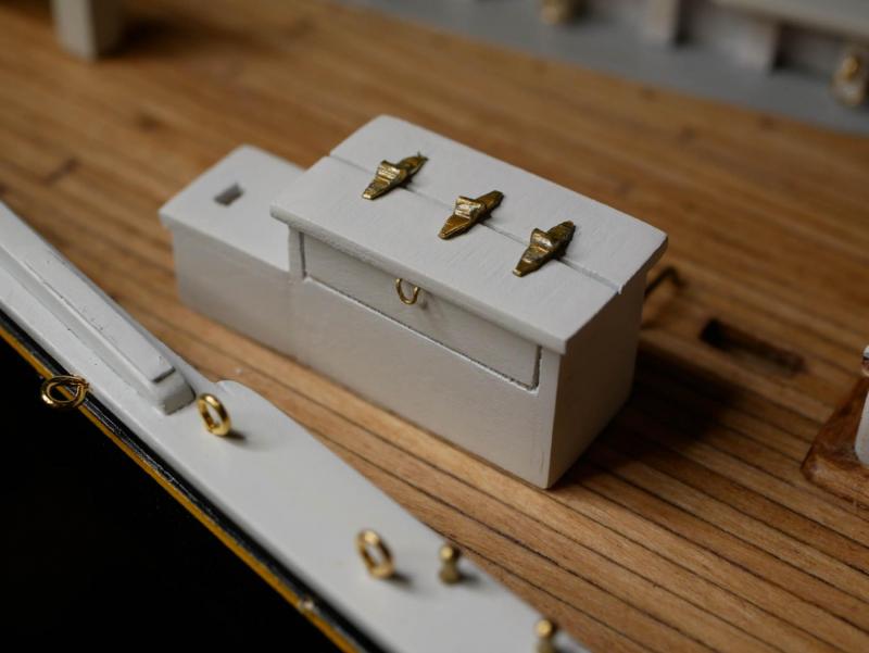
Thanks Russ! Over the last week or so, I've gotten the bowsprit bitts/samson post and the engine box completed. The bowsprit bitts and samson post were pretty straight forward as the kit provides the key piece as a laser-cut item. The whole thing went together pretty quickly. The engine box gave me a bit more trouble. My first attempt was fine until I got it painted, then I notices a few too many imperfections in the wood. I tried to fix them with some filler and repaint, but wasn't happy with the results. The second attempt failed during assembly - I wasn't able to get it square enough. My third attempt was successful. This time I made a much more rigid internal frame for the box, then used 1/16" sheet material for the 'walls'. The lift out door on the side was simulated by cutting one of the side panels halfway through (so it remained one piece, but looks like two). The smaller part of the box was built similarly, but I left some open space on the inside frame since this piece has three holes in the walls. The holes were made by drilling holes then using needle files to square them off. They aren't perfect, but it is what I was able to do with the tools on hand. The entire thing was primered and airbrushed white. I decided to try and simulate the hinges on the top. I used some thin brass strip I had on hand and some thin brass rod. These were soldered together. Once soldered, the three pieces were cut apart and each piece was cleaned up. I filed away a lot of the solder (I always make a mess when soldering), and trimmed the brass strips to be shorter and tapered. I touched them up a bit with some brass paint to make the color a little more consistent. They were then glued on to the roof of the engine box. I also simulated a small handle/latch using some thin brass wire that came with the kit. I noticed after I glued it on the deck that despite all my attempt to double-check things, I managed to screw something up. I glued the smaller portion of the engine box so it lined up with the outboard edge of the larger box. It should have been even with the inboard edge. I don't think anyone would notice this once the ship is done (except for me or another Bluenose builder). So, rather than rip it off and risk damaging the deck, I'm going to leave it. Fortunately when I was positioning it, I was using the inboard hole on the smaller box and the samson post as reference points, since the windlass/machinery touches both of those. So really, the small box is in the right place and the larger box (which nothing else connects to) is just out of position by a small amount. I don't think there is anything else I can work on to procrastinate - I've got to start in on the windlass and machinery. It shouldn't be difficult, and it will be similar in process to a lot the work I did on some Model Airways WWI aircraft a few years ago (which use a lot of cast pieces to build up the engine). My fear is that there is a lot of potential for detail with this stuff, and my ability to toss stuff and start over will be limited by the use of cast metal pieces.

- 245 replies
-
- 11
-
-
- bluenose
- model shipways
- (and 1 more)
-
Mini Mill recommendations
genericDave replied to StebbinsTim's topic in Modeling tools and Workshop Equipment
Lots of great info in this thread, and very timely! I've been considering a small mill for a while, and decided to 'strongly hint' that I wanted one for Christmas from the wife (in combination with my birthday which is a week earlier). She informed me last night that she is giving in, and the mill should be here this weekend. I ended up going with the Proxxon MF70. From my reading, I agree with all the advantages of the Sherline, and we weren't really concerned with the price difference. For me, the choice of the MF70 was first driven by size - the MF70 is a little smaller than the Sherline. Since I don't have dedicated space for power tools, I have to store them in a closet and pull them out when I want to use them. That little bit of savings in size often makes the difference when deciding if I want to bother pulling the machine out or not. I fully expect that some day (when I have more space), I'll be upgrading many of my tools. I was also impressed with the number of people online who have converted the MF70 to be computer controlled. CNC is overkill for my purposes, but converting the MF70 looks pretty easy (a couple hours), fairly inexpensive (I've ordered all the parts - around $300 total), and easy to undo as it doesn't modify the machine at all (with the right parts, you just unscrew the handles and replace them with the motor mounts). I'm playing with the CNC conversion mostly just for fun, since I have zero experience with the software used to drive it I wouldn't be able to do anything complex, but I suppose I have to start somewhere. -
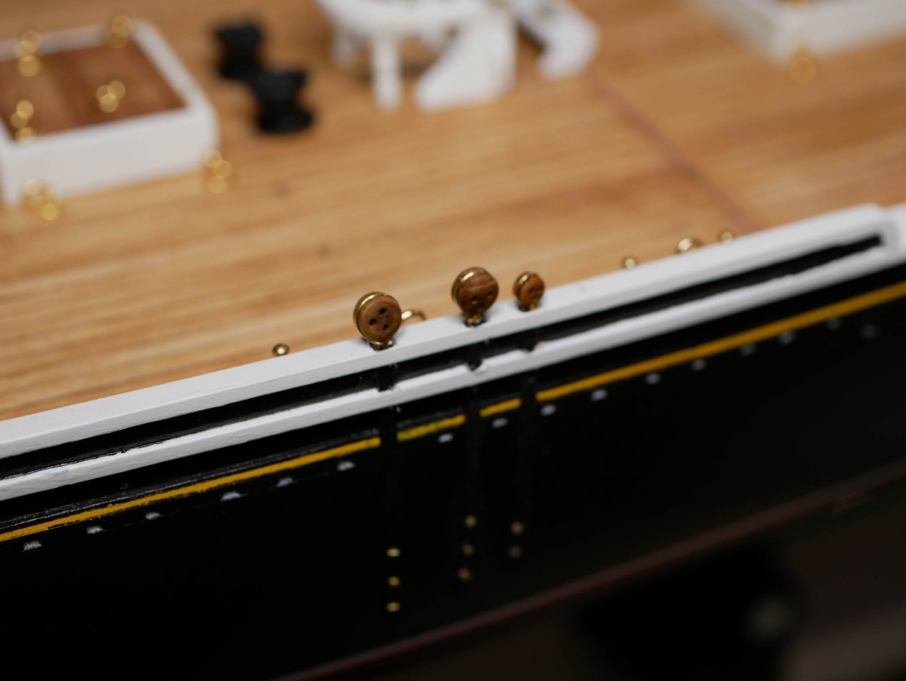
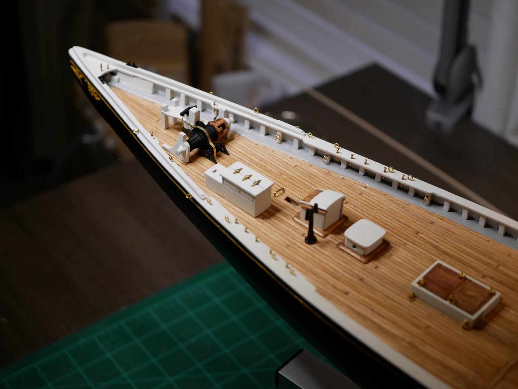
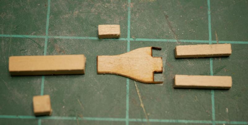
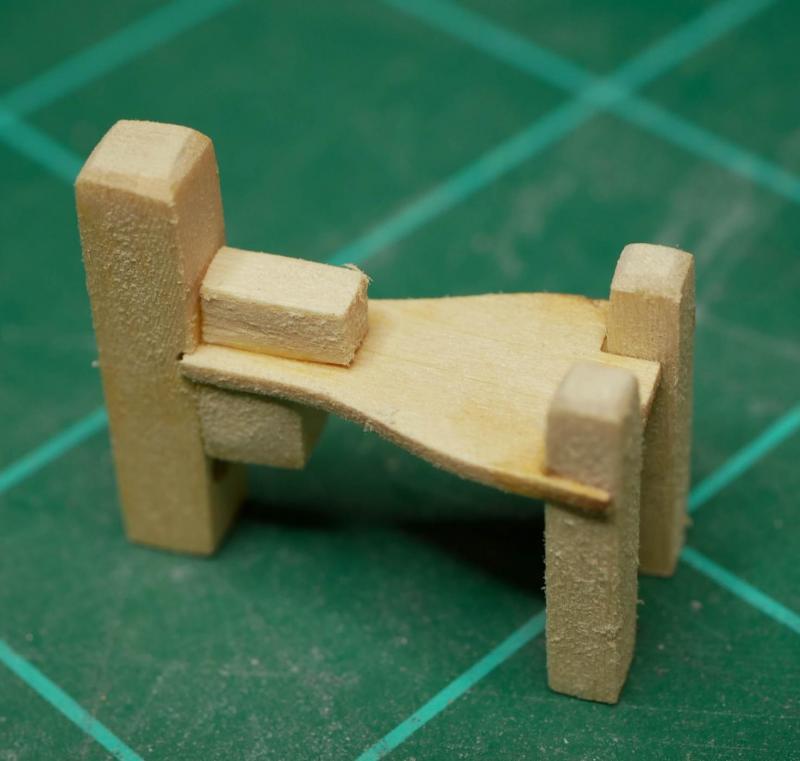
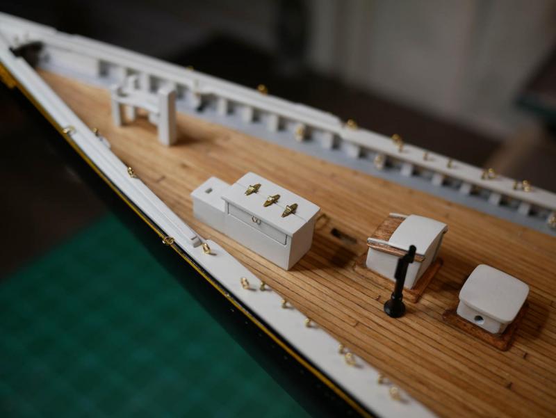
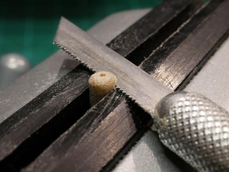
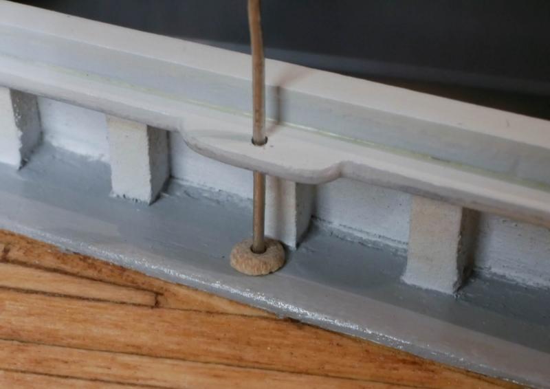
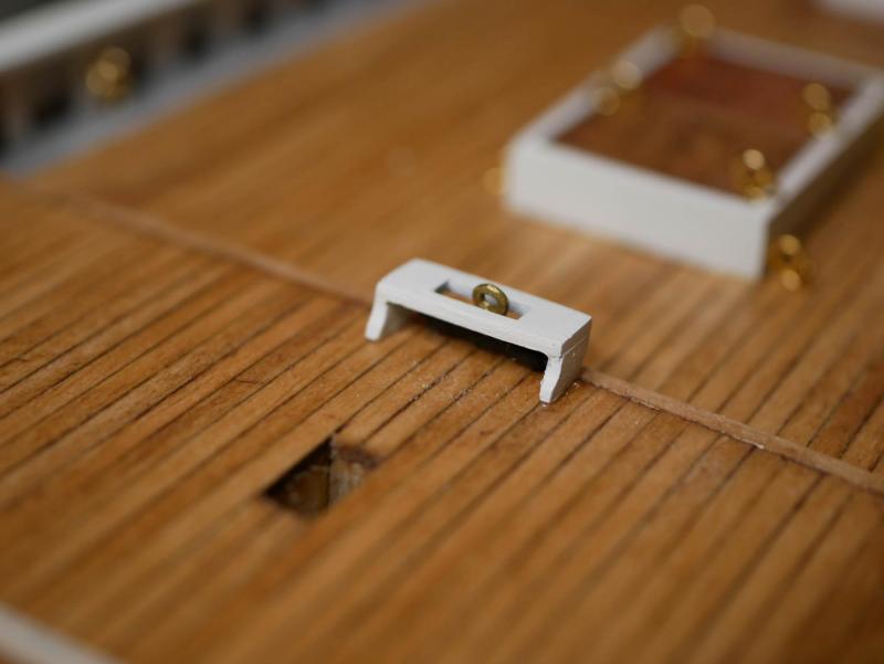
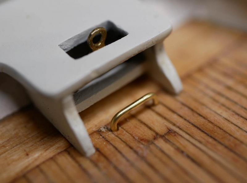
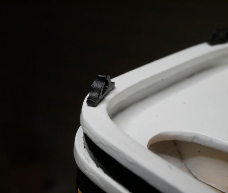
Lots of random work over the last few days. I've now got everything in on the deck except all the bowsprit stuff / windlass / machinery. The galley stack was pretty easy. Just cleaned up the casting, removed the large 'pin' on the bottom and replaced with a thinner brass rod for mounting to the deck, painted it, and glued it in. The 'jumbo jib sheet traveler horse' takes longer to say than it took to install. Just some bent brass rod installed in front of the hole for the fore mast. Then came the catheads. I thought these would go quick, but they ended up taking a couple hours. Part of the problem was that I couldn't find any good photos/information online that showed in detail how the anchor hangs from these, or how the ropes/chains are handled. Lots of information about catheads in general, but nothing on the specific versions used on the Bluenose. I did finally find a fantastic diagram on page 399 of Howard Chapell's 'The American Fishing Schooners 1825-1935'. Once I understood how this would get hooked up, I decided to build them now but not glue them in. I'll wait to secure them until I hang the anchors in case I need to make further alterations. The cast metal pieces were cleaned up. A hole was drilled in the fore side of each one, only halfway through the head, to hold the eyebolt that attaches to the bar. Another hole was drilled all the way through the head from the top, This second hole will be used to attach the chain. The eyebolts that come with the kit are way too big for the catheads, so I made some simple ones out of some wire I had on hand and glued them in. The plans show some sockets on the waterways that the base of the cathead sits in. I decided to try and simulate these. I cut a short length of a very small dowel rod and drilled a hole through it. I rounded off the top, and used a razor saw to cut just a thin piece off the top. This ended up making a fairly decent socket. It doesn't have the detail shown in the plans, but I'm not yet at a point where I could pull off that detail on a piece so small. The sockets were painted black and glued in after they dried, and while the paint was out the catheads themselves were also painted black. Eyebolts were added to the rail for the bar, and the bar was fashioned from the thicker brass wire provided with the kit. Turned out pretty well. These were fitted on the ship, then removed and put back in storage until later when I mount the anchors. The anchor pads were cut from some 1/64" thick sheet wood I had handy. These were pretty straightforward, just small and hard to sand. One last step before starting in on the bowsprit bits / windlass / machinery is to get all the belaying pins and eyebolts installed. I had originally planned to do this later, just before rigging, but I decided it would be easier to do now before the deck is completely full. Installation of the pins and eyebolts was typical - mark locations, drill holes, glue in pieces. I was very happy with the quality of the belaying pins in this kit. 39 belaying pins and 20 eyebolts. Today I'm taking some time to touch up some paint on the bulwarks, and I'm pulling everything out of the workbench and doing a complete cleaning. Hopefully I'll be diving into the deck stuff near the bow tomorrow!


- 245 replies
-
- 4
-
-
- bluenose
- model shipways
- (and 1 more)
-
Bob - I remember seeing that on your build log. (And I was just looking at your log this morning!) I didn't realize how unhappy I was with my original fife rail until I had the whole thing glued together and covered in primer. The biggest problem was that I introduced some 'wavy-ness' as I was gluing things together due to the thin rail piece. As I started sanding the primer, the force I was putting on it only made it worse. I tried to use some CA glue to strengthen some joints, which made an even bigger mess If I run into something like this again, I'll definitely try to strengthen up the thin pieces before I begin assembling anything. I've got a 1/64" thick sheet of some hardwood I found at a local hobby store a year or so ago that would probably do a great job at adding a little more strength.
- 245 replies
-
- 2
-
-
- bluenose
- model shipways
- (and 1 more)
-
Russ, I got curious so I did some checks against the plans as to scaled sizes. I used 3/32" thick material for all the parts, which at this scale would be about 6" thick. The kit provides 3/32" thick laser cut pieces for the knees, and seems to indicate 3/32" thick material for the square posts. The metal castings for the 'fancy' legs appear to be 3/32" thick as well. So on all those, I think I actually ended up at the correct size. The bar and the rail itself are 3/64" thick laser cut pieces in the kit, which would be about 3" thick if I did my math right. I used 3/32" for those, so I'm at 6" thick - about double. I think I only ended up out of scale on those two pieces, which I can live with. Once I get pins in there and some rigging line, I don't think it will be noticeable at all.
- 245 replies
-
- 1
-
-
- bluenose
- model shipways
- (and 1 more)
-
Thanks Russ! I do my best to stick to scale, but since this is only my second build, I'm still at a point where I'll sacrifice scale for ease-of-building or even a general 'can I even build it'
-
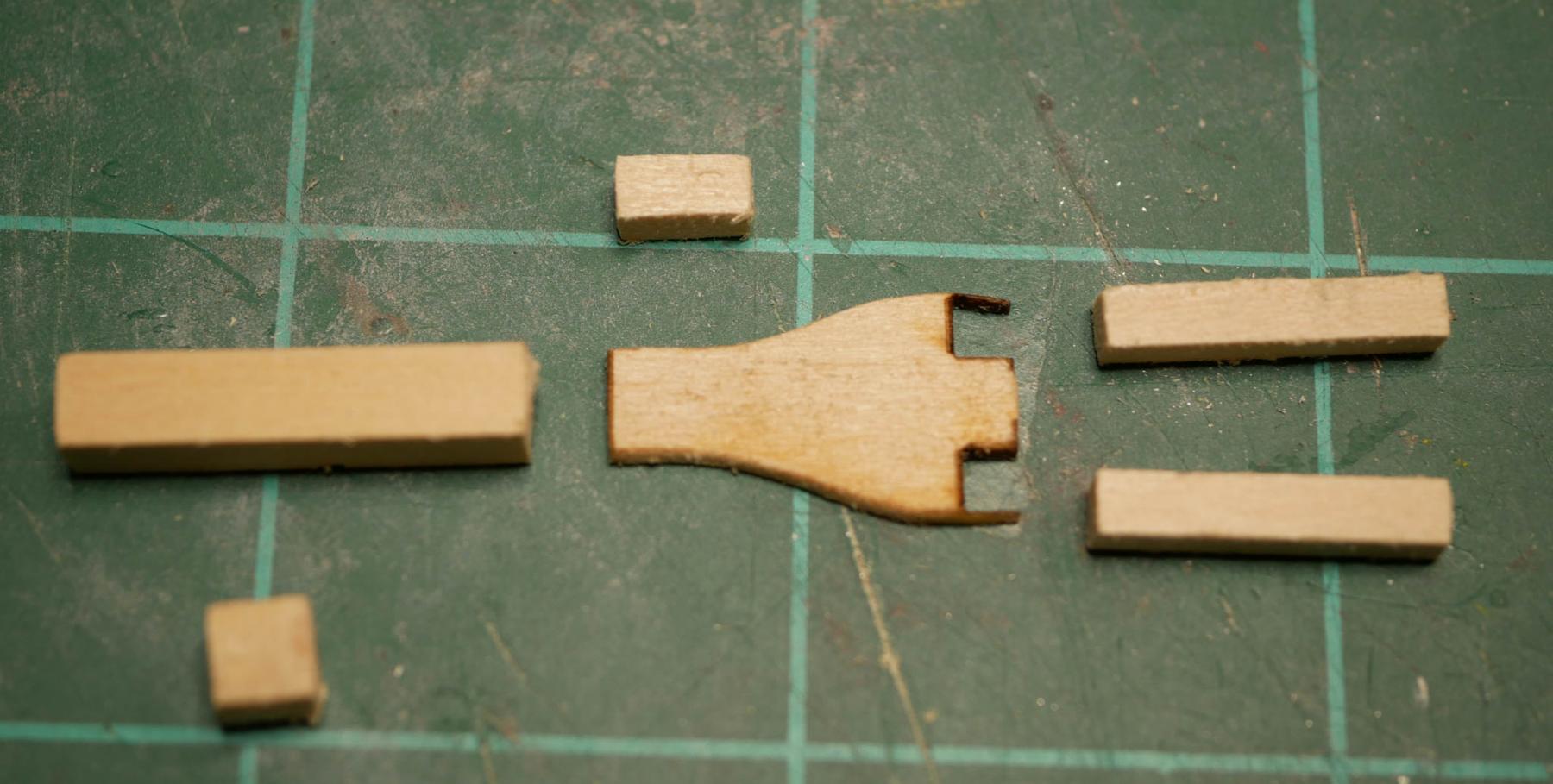
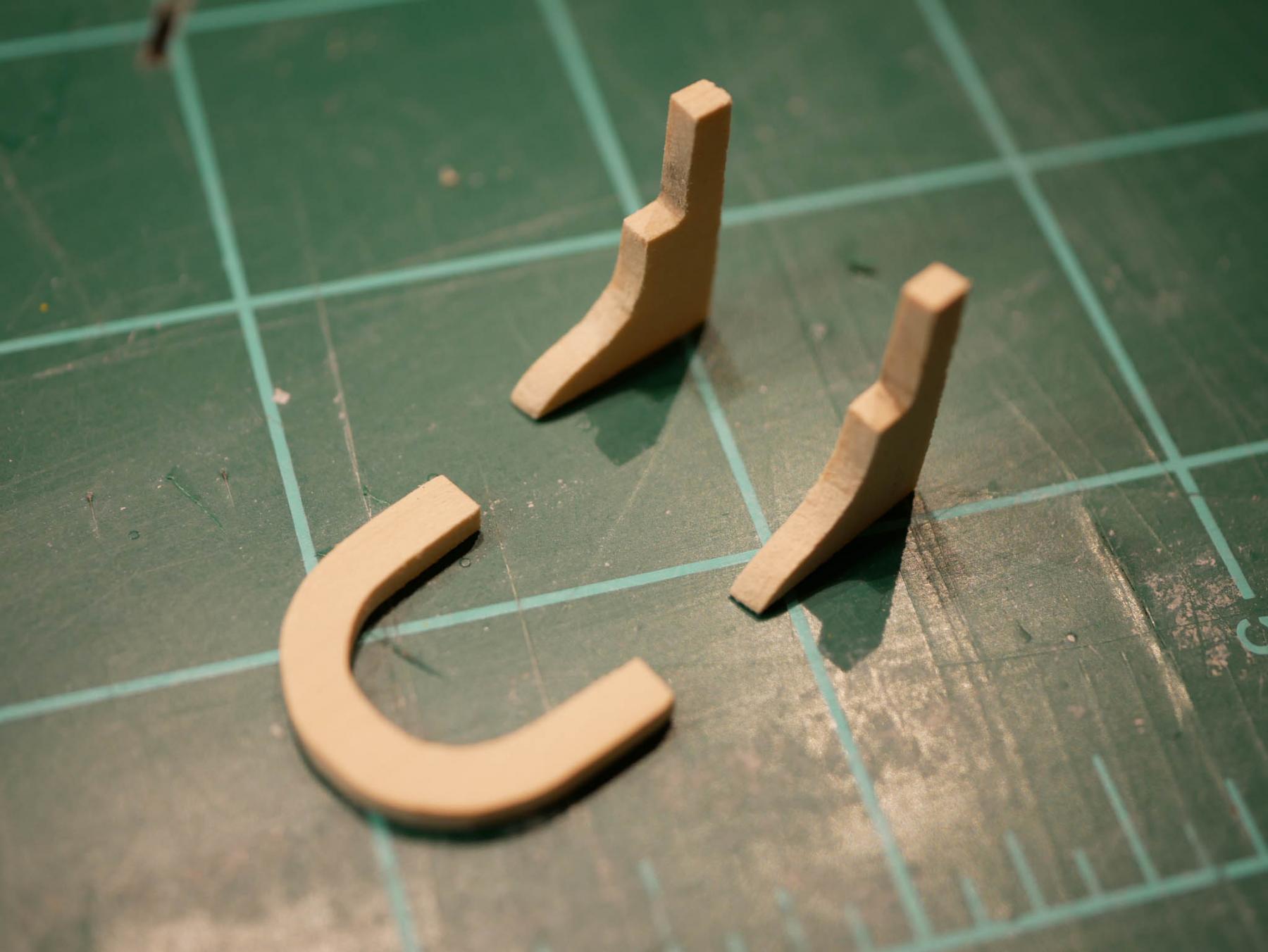
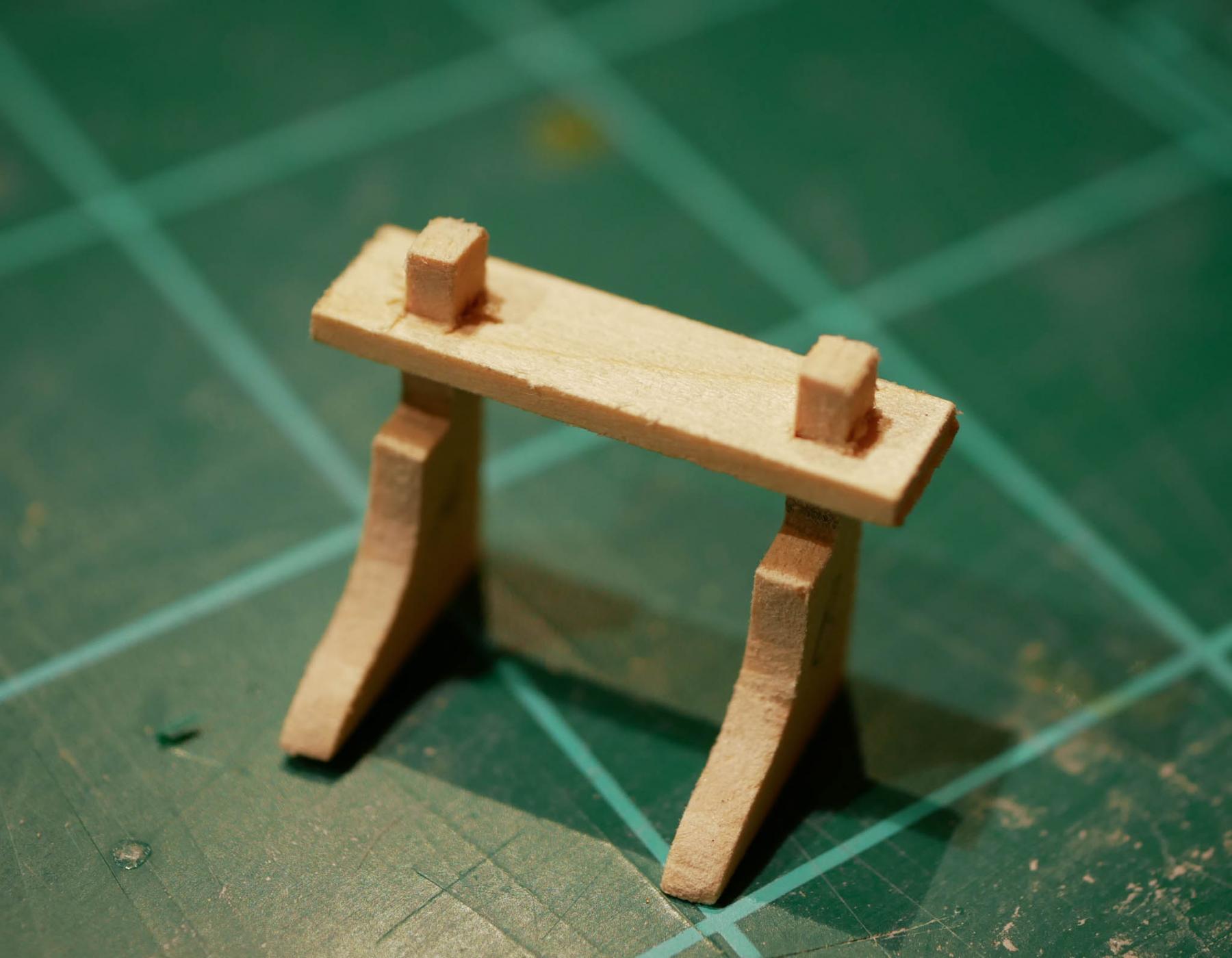
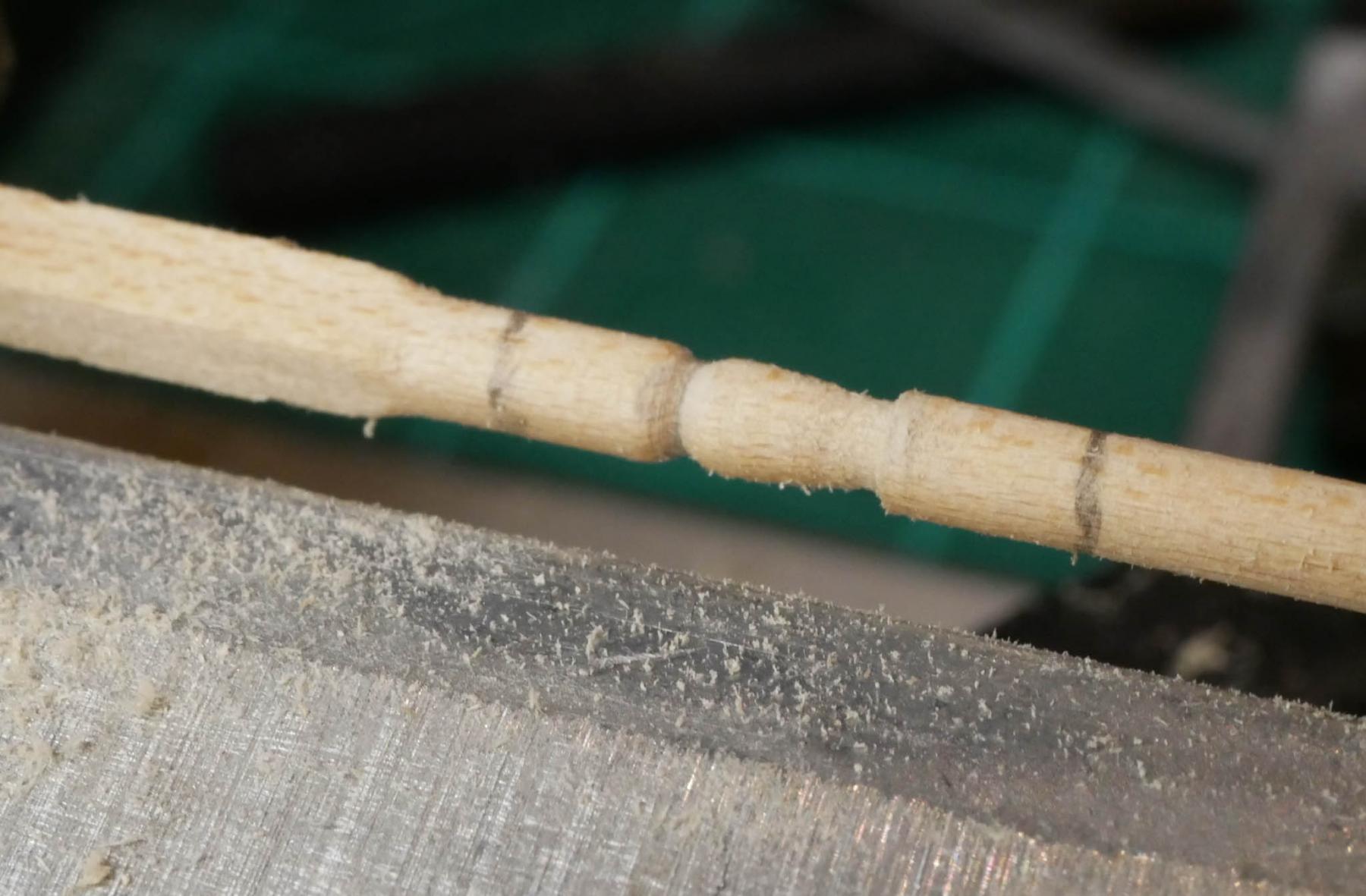
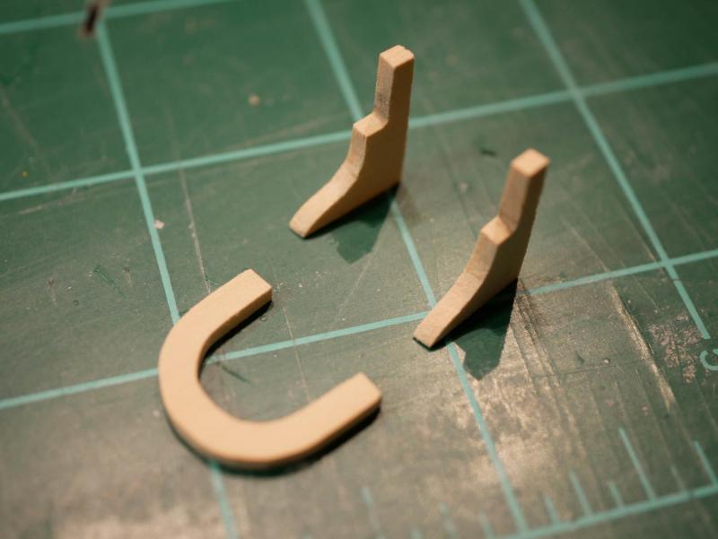
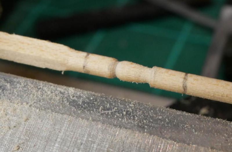
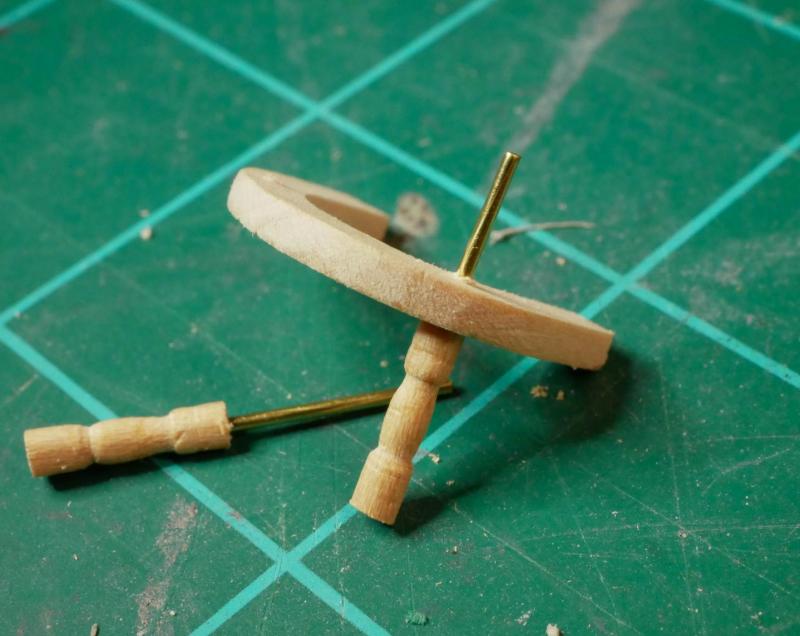
Thanks Steve! Tonight I was able to get the fife rail built. This is my second attempt. Over the weekend I built the fife rail using the laser-cut pieces provided by the kit, but I wasn't happy with the results. The provided pieces are very thin, and I wasn't able to get them aligned well while gluing. Things ended up being uneven, and the whole assembly felt flimsy. So tonight I started from scratch. I transferred the shapes for the rail and legs onto a 3/32" thick basswood sheet. I cut these out using my Proxxon scroll saw. (When I bought the scroll saw, I didn't realize how much I'd use it. This small scroll saw has become the most-used power tool I own). I made the legs and the posts out of single pieces to make the structure more rigid. The bar across the top was cut by hand, and the holes for the posts were drilled out with a drill bit, then squared off with a needle file. The slot for the boom crutch was cut with a #11 blade then cleaned up with a tiny needle file. To make the 'fancy' legs, I stuck a length of square basswood strip into my little lathe. I'm not very experienced at using a lathe, so as long as they turn out halfway decent, I'm happy. Once the legs were done, I put some pins in the top using some short pieces of brass rod. I drilled holes through the fife rail, and glued the legs in place. The rest was assembled pretty easily. Since I used slightly thicker material than the kit provided, the entire structure was much more rigid than the original fife rail. This really helped when it came to sanding and painting. I glued in some short pins in the bottoms of the legs - these will be used when I secure the fife rail to the deck. For now, I'm leaving the fife rail loose. I'm going to wait to permanently mount it until I start working on the masts. I don't want to screw up and have the fife rail slightly mis-positioned and prevented the mast from being at the correct angle. Overall I'm very satisfied with my new fife rail. The material is a little thicker than the kit provides, so it is probably slightly out of scale, but I think the added stability is worth it. I'm now done with the quarter deck, and moving on to the fore deck.


- 245 replies
-
- 4
-
-
- bluenose
- model shipways
- (and 1 more)
-
Thanks Elijah!
-
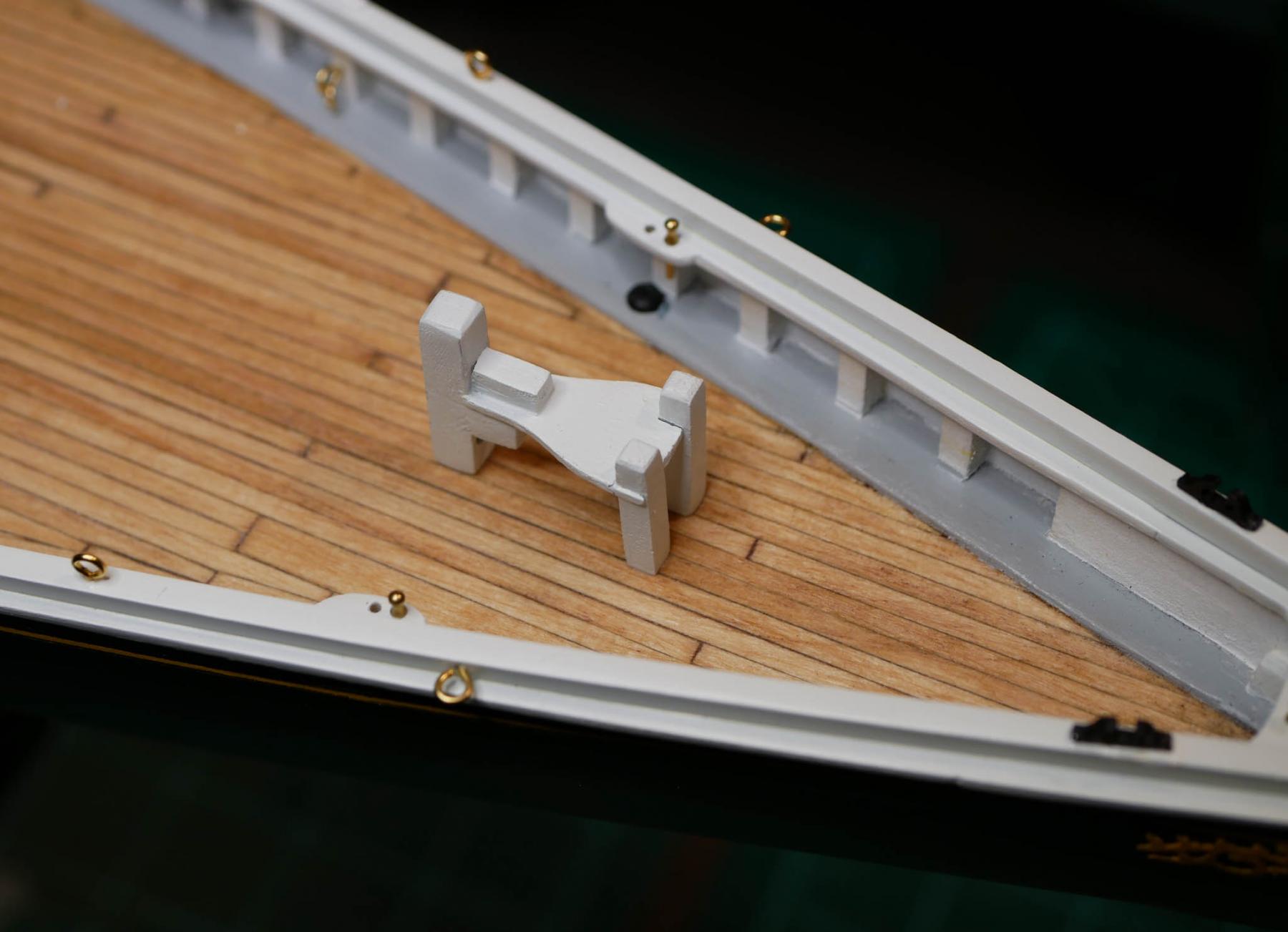
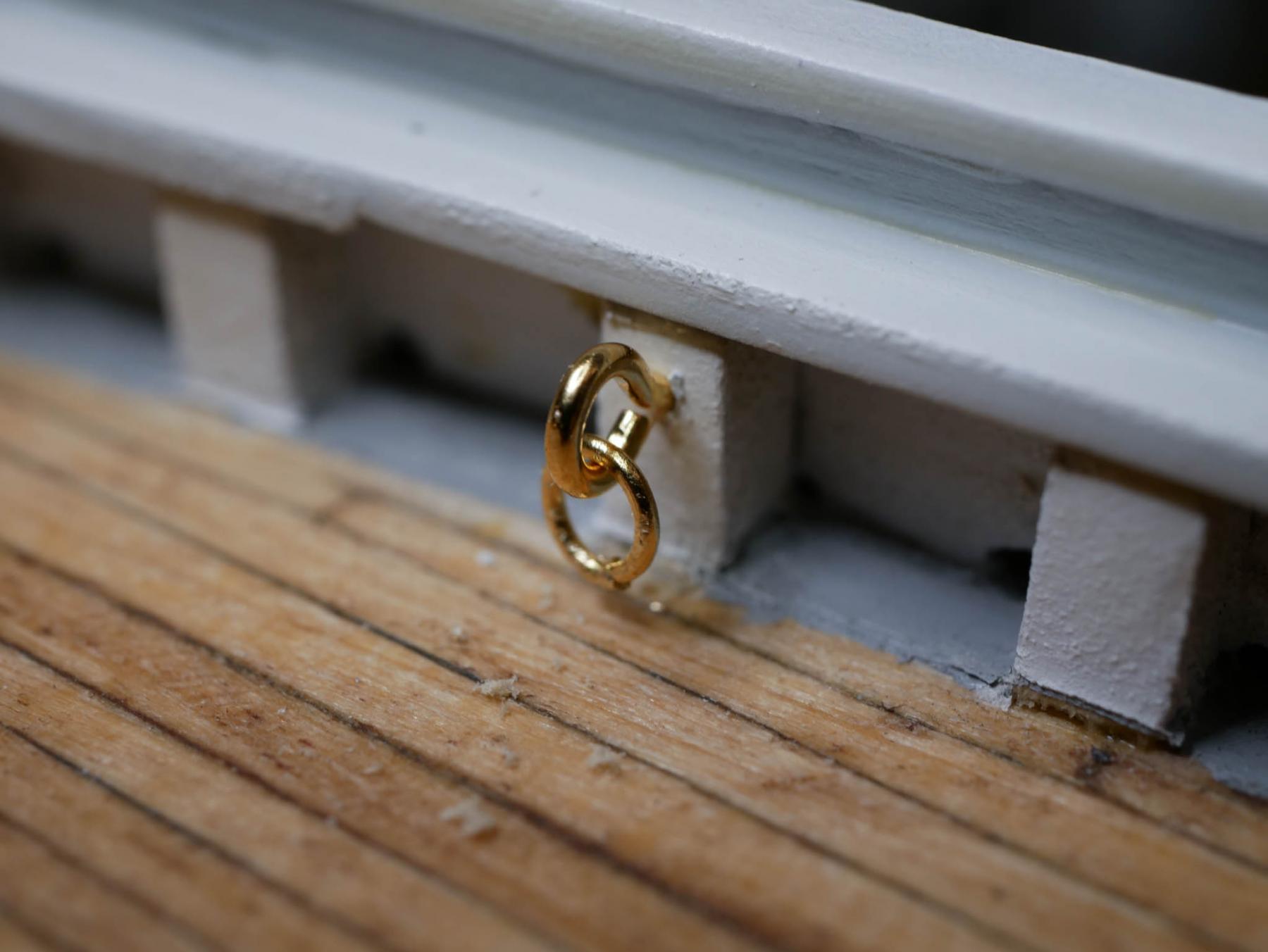
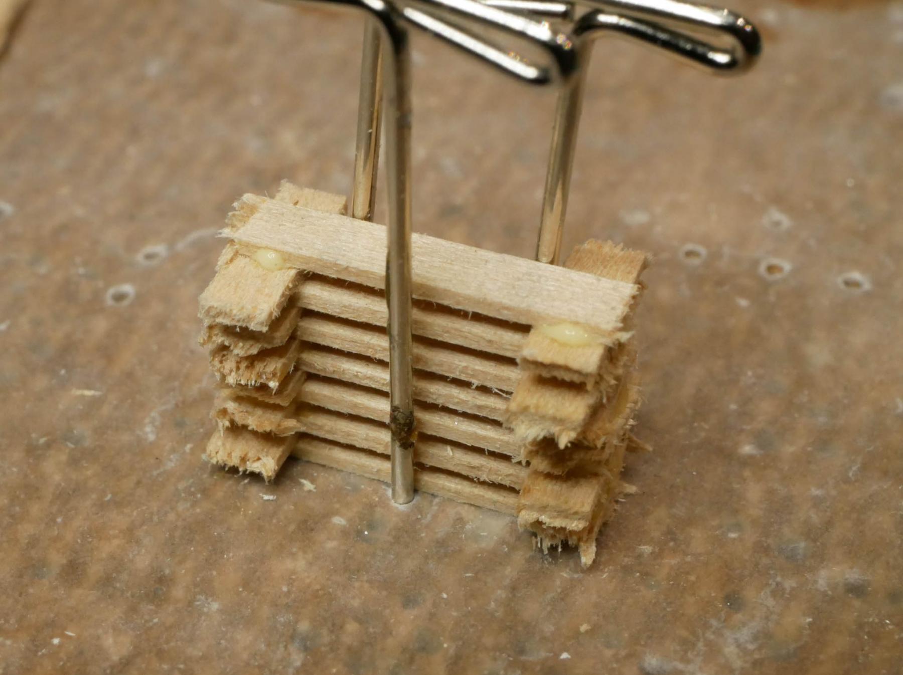
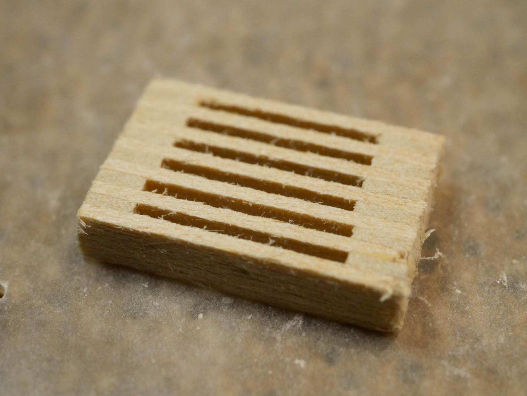
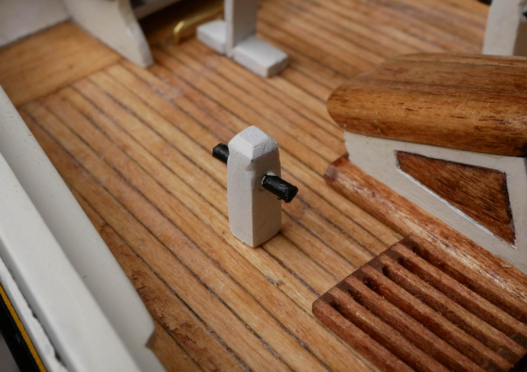
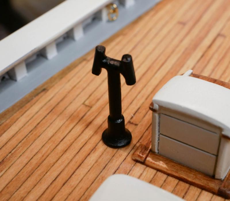
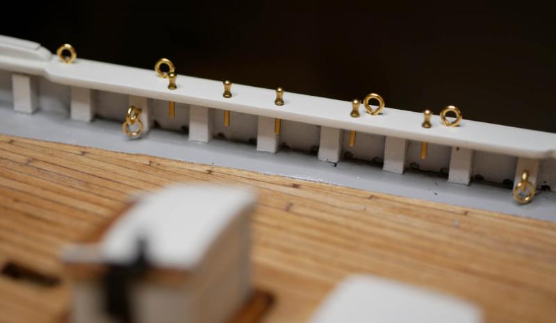
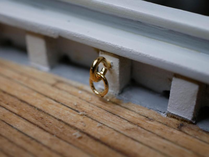
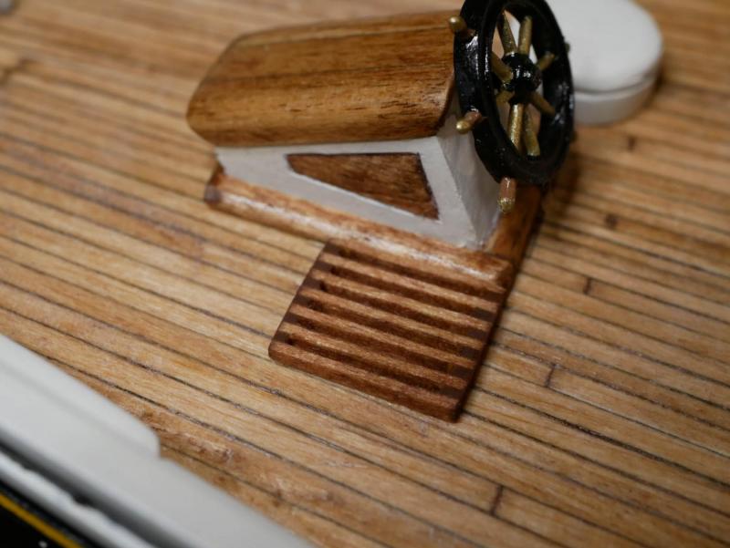
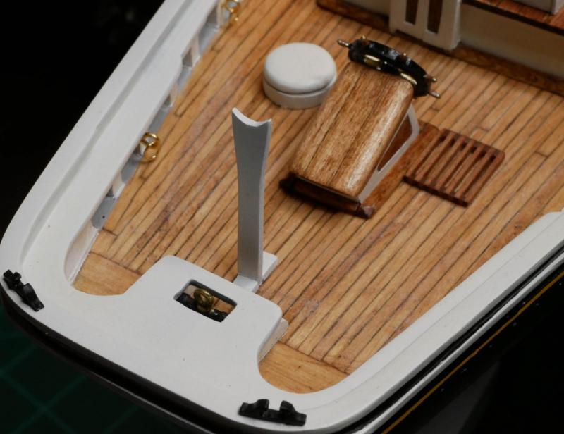
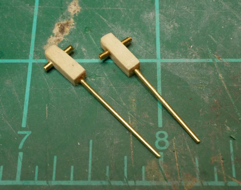
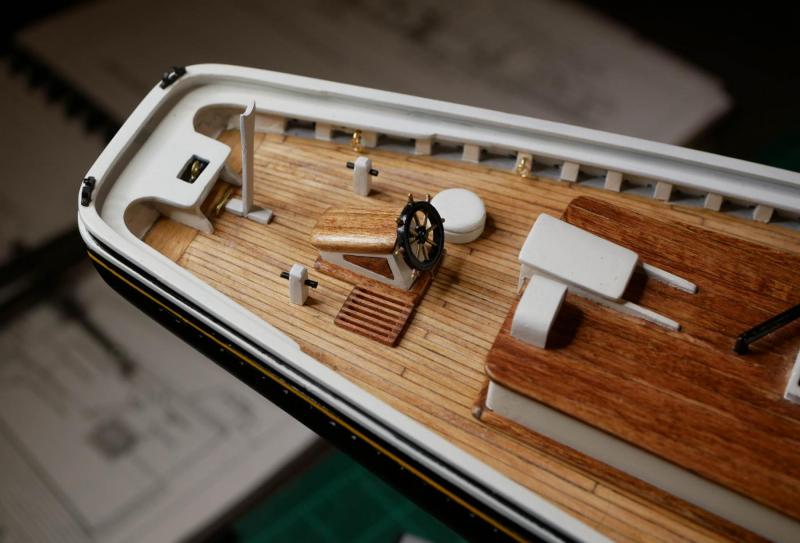
I feel like I've hit a 'fun' part of the build - lots of small projects that go pretty quickly. I have been waiting to seal the deck with clear poly until I had the major deck structures ready. Now that I've got them ready, I need to stop procrastinating and seal the deck. Before gluing the structures down, I installed a number of eyebolts and rings on the stanchions inside the bulwarks. These won't be used for a while, but I think it will be way easier to install these before the deck gets cluttered. I've decided to leave the brass fittings as unfinished brass. I know that these would likely have been black on the ship, but if I paint them, I know the paint will likely rub off during rigging. I've tried using blackening solution with little success. So, I'm just going to leave all these as natural brass. With those in place, I marked the locations of all the deck structures and glued them down. Then I applied some Minwax Wipe-On Poly to give the deck a clear finish. I've been using a satin clear coat for everything so far, but I decided to go with gloss for the deck. It is only a slight difference, but I like having a little bit of shine on the deck. Once the poly was dry, I finished installing all the various eyebolts and rings for the hatches. Next it was on to the assortment of other miscellaneous things that need to be installed on the deck. I'm tackling the rest of the deck in three 'phases'. First I'm going to get all the 'stuff' installed on the quarter deck. After that, I'll tackle the fore deck, except for the windlass and machinery. Finally, I'll build all that equipment up near the bow. So, on the quarter deck... First up were the battons. I had no idea how to make these. I ended up gluing a bunch of 1/32" strips together, then sanding them down to get close to the right size. The 'slats' are a little larger than the plans call for, but I don't think they look awful. Next I installed the boom sheet buffers. These were cast metal pieces. The pieces were cleaned up, painted, and installed. The fore boom sheet buffer has a platform that gets made from some laser-cut pieces provided by the kit. Since I'm leaving rings and eyebolts as brass on the ship, I painted the rings on the boom sheet buffers brass to match. I made the main sheet lead block horse from some brass rod, bent to the right shape, and installed it just in front of the main boom sheet buffer at the stern. The main boom crutch was assembled from the laser-cut piece and some strip wood. Next up were the quarter bitts. I decided to use some brass rod for the 'arms' that extend out from the posts. I'm not confident I could have made wood pieces look good at that size. I glued some long pins to the bottom to use as handles during painting. Once the painting was done, these pins were trimmed shorter and used to help secure the bitts to the deck. I also installed the bilge pumps and stern chocks, which were all provided as cast metal pieces. This completes the pieces on the quarter deck, with the notable exception of the fife rail. I actually did build the fife rail, which was quite a project, but I'm not happy with it and will likely rebuild it with scratch-made pieces. I knew the fife rail was going to be a challenge because I was missing one of the fancy 'legs' that the kit provides as cast metal pieces. Rather than get a replacement, I decided to make my own using the little Proxxon lathe I've had sitting in the closet. Surprisingly, they turned out great. The problems with the fife rail came as I was trying to glue everything together. The pieces were all so small and thin that it was difficult to get everything squared up. What I ended up with is usable, but not as pretty as I'd like. So I think I'm going to take a stab at making a new one from scratch. If that fails, I can fall back to using the ugly one I made from kit parts. Even though I hit a bit of a stall with the fife rail, I'm really happy with the recent progress. The deck is looking more and more complete every day,


- 245 replies
-
- 4
-
-
- bluenose
- model shipways
- (and 1 more)
-
Jerry, Congratulations on the build! It looks great! Selfishly, I'm little sad to see that you've finished . Your regular updates and progress really helped to me motivated during the slow time on my own build! Can't wait to see what you tackle next!
-
Companionway Not super-exciting, but the companionway for the fore deck is finished. Kinda surprising something so small required so much work.
- 245 replies
-
- 8
-
-
- bluenose
- model shipways
- (and 1 more)
-
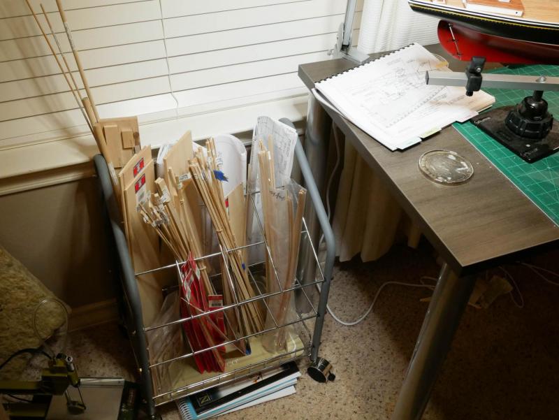
I settled on this storage solution a few months ago. My "workshop" is in the corner of my home office, so I needed something that kept all the strips handy and organized, but still looked nice enough that the wife would let me keep it in the house. I bought a rolling organizer for architectural plans. It lets me organize things into the different spaces and also holds the plans (obviously, since that is what it is designed for). I keep the various sizes bundled together and labeled.
-
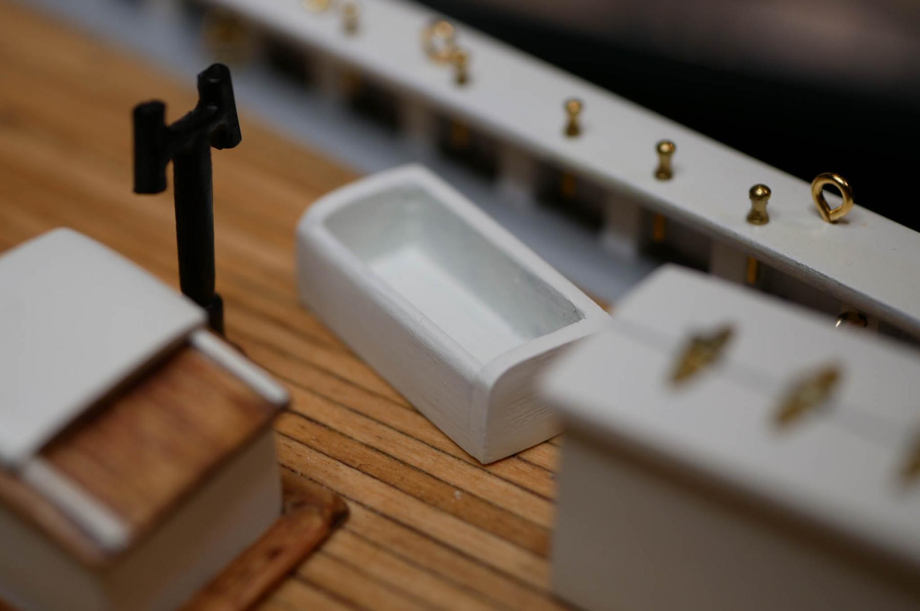
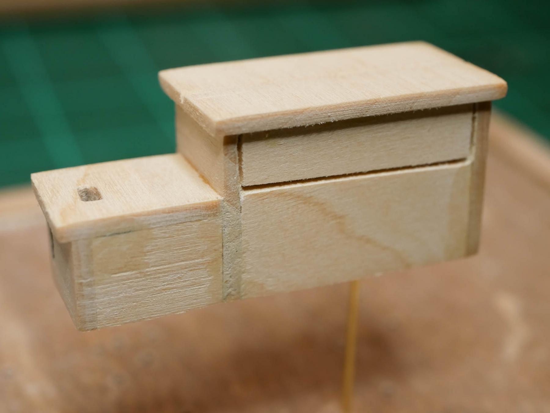
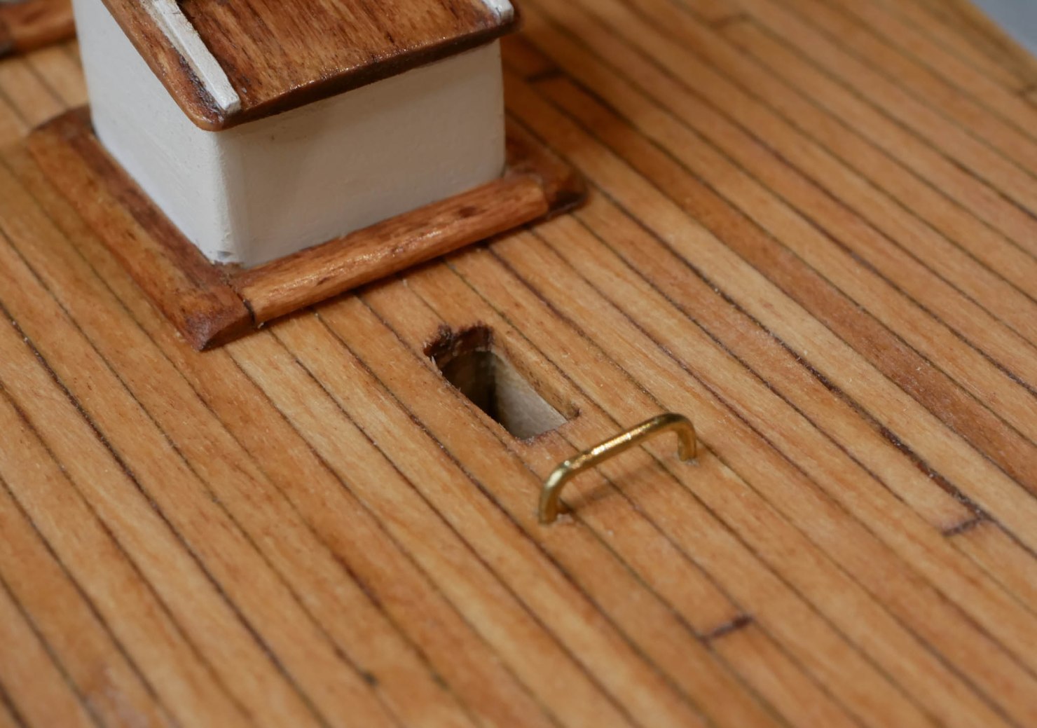
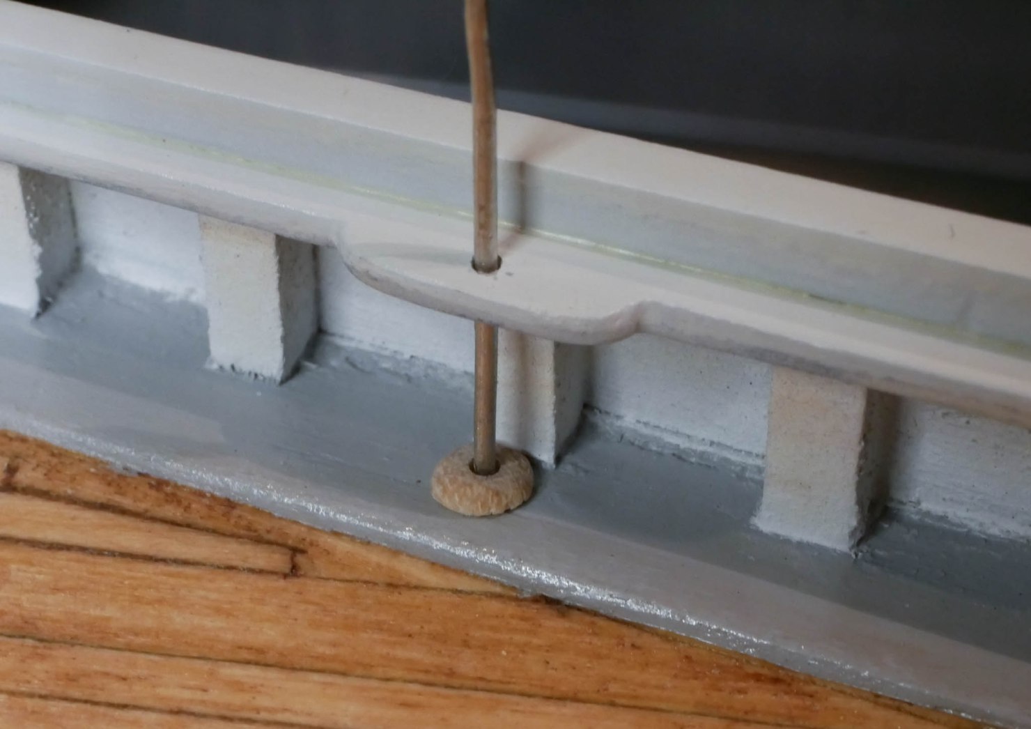
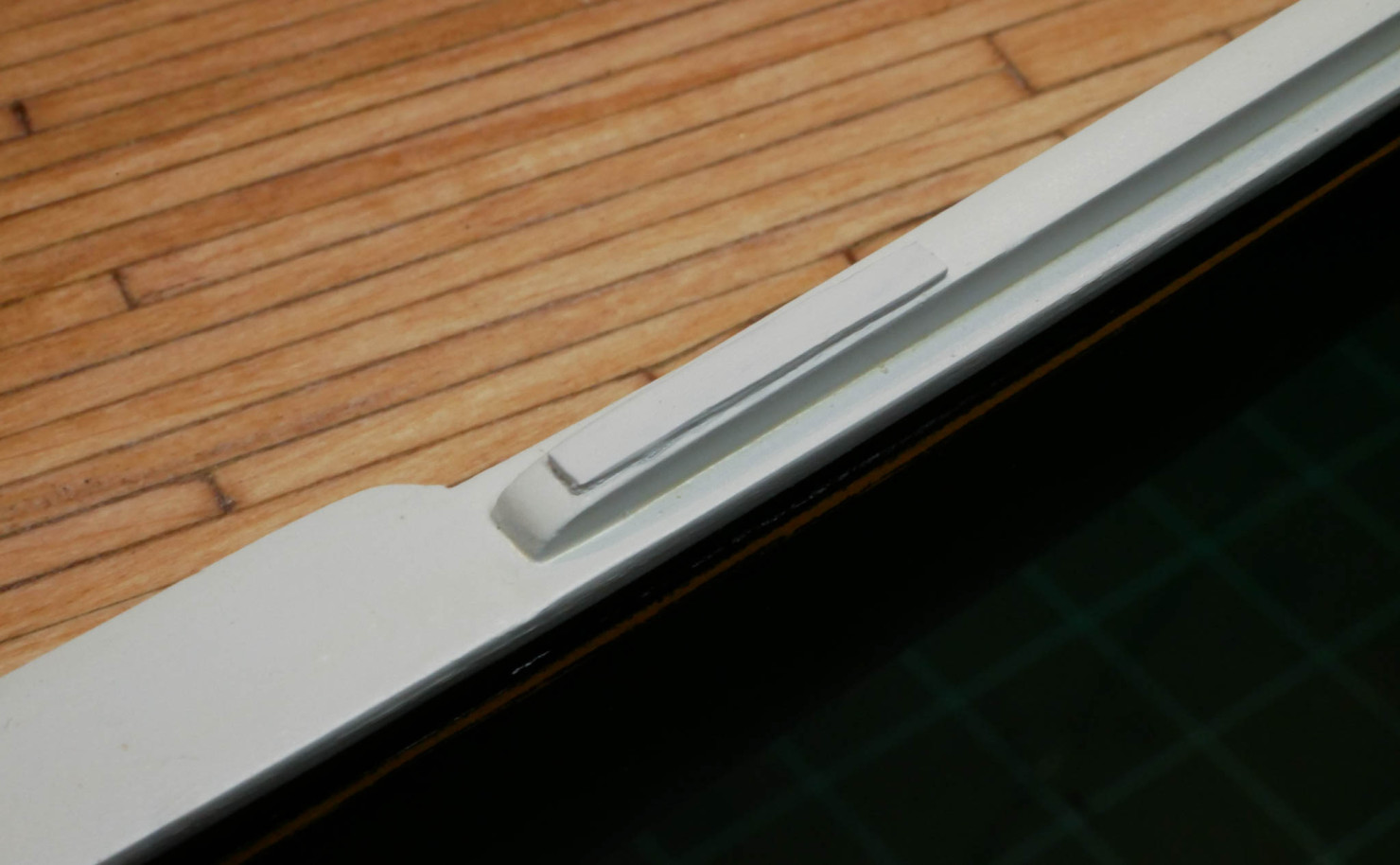
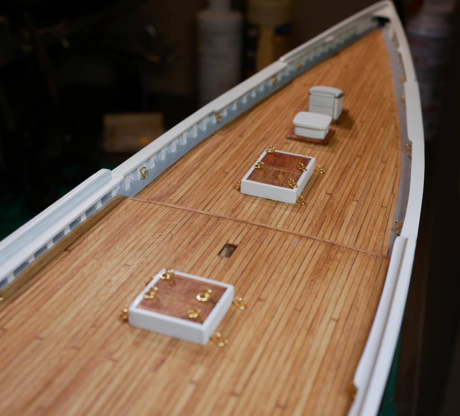
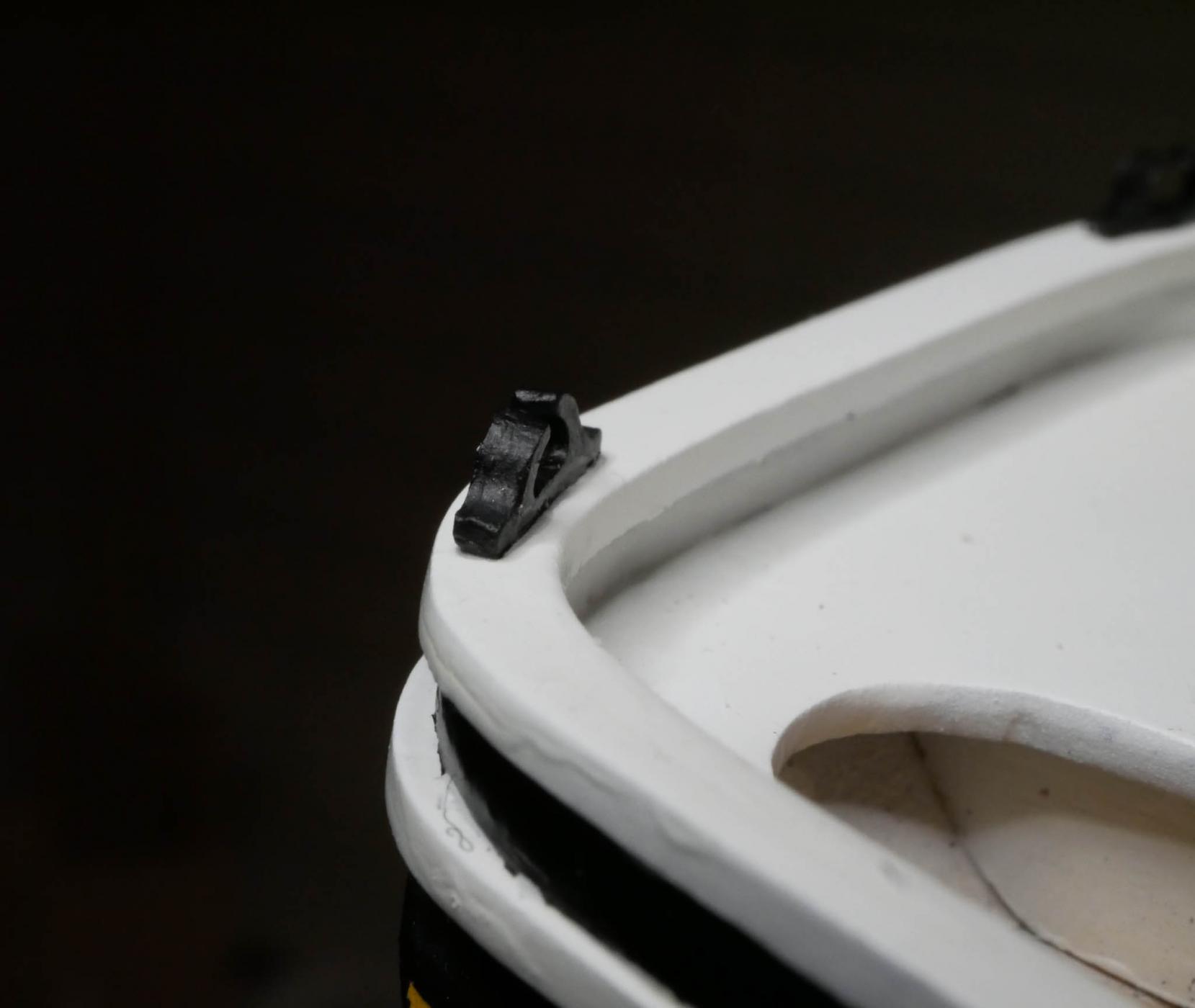
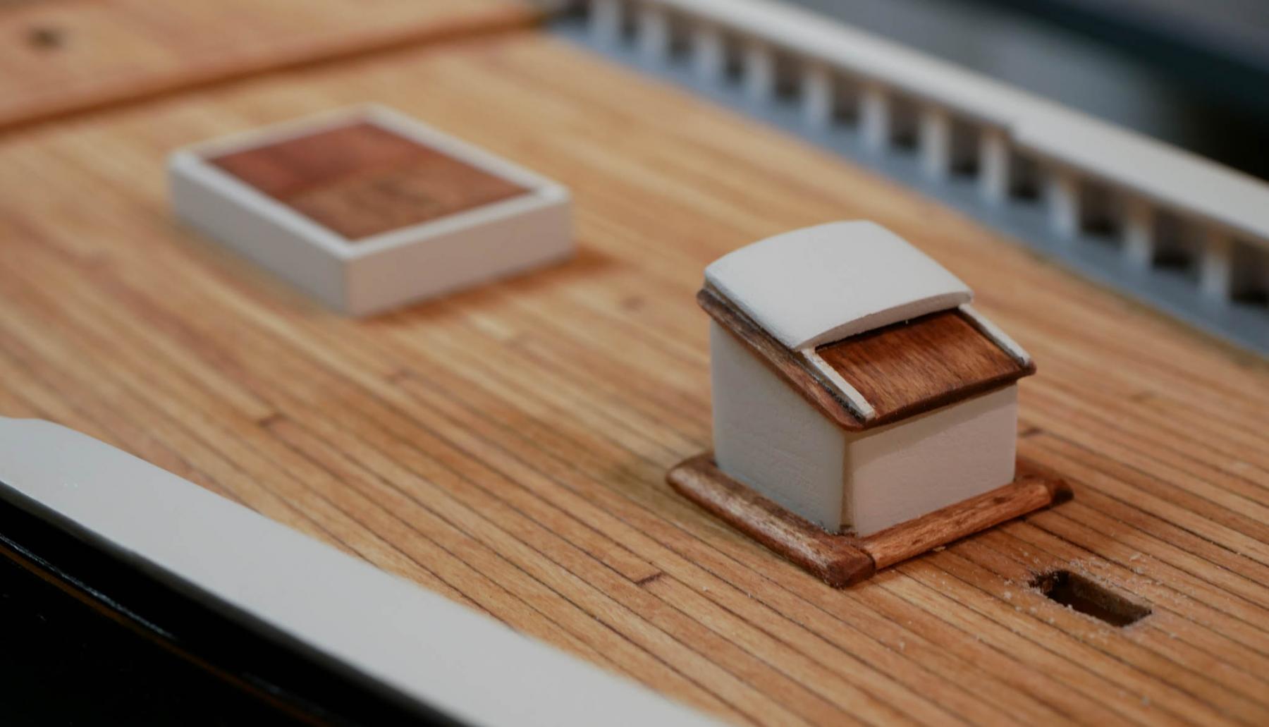
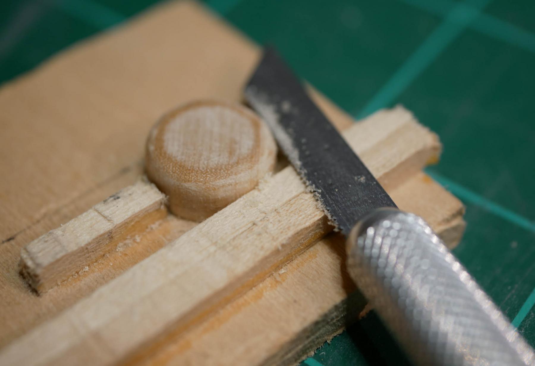
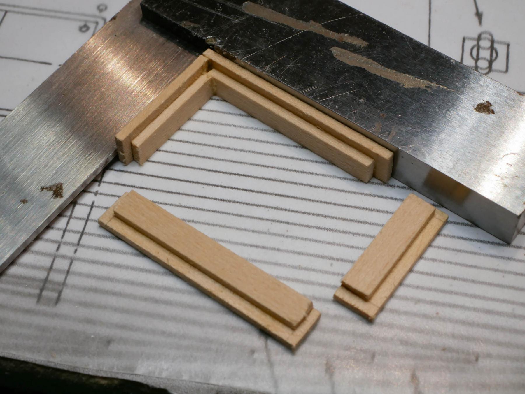
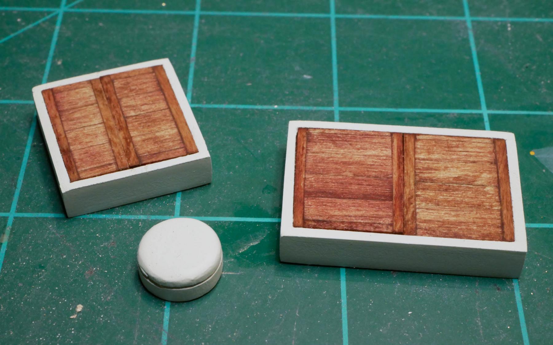
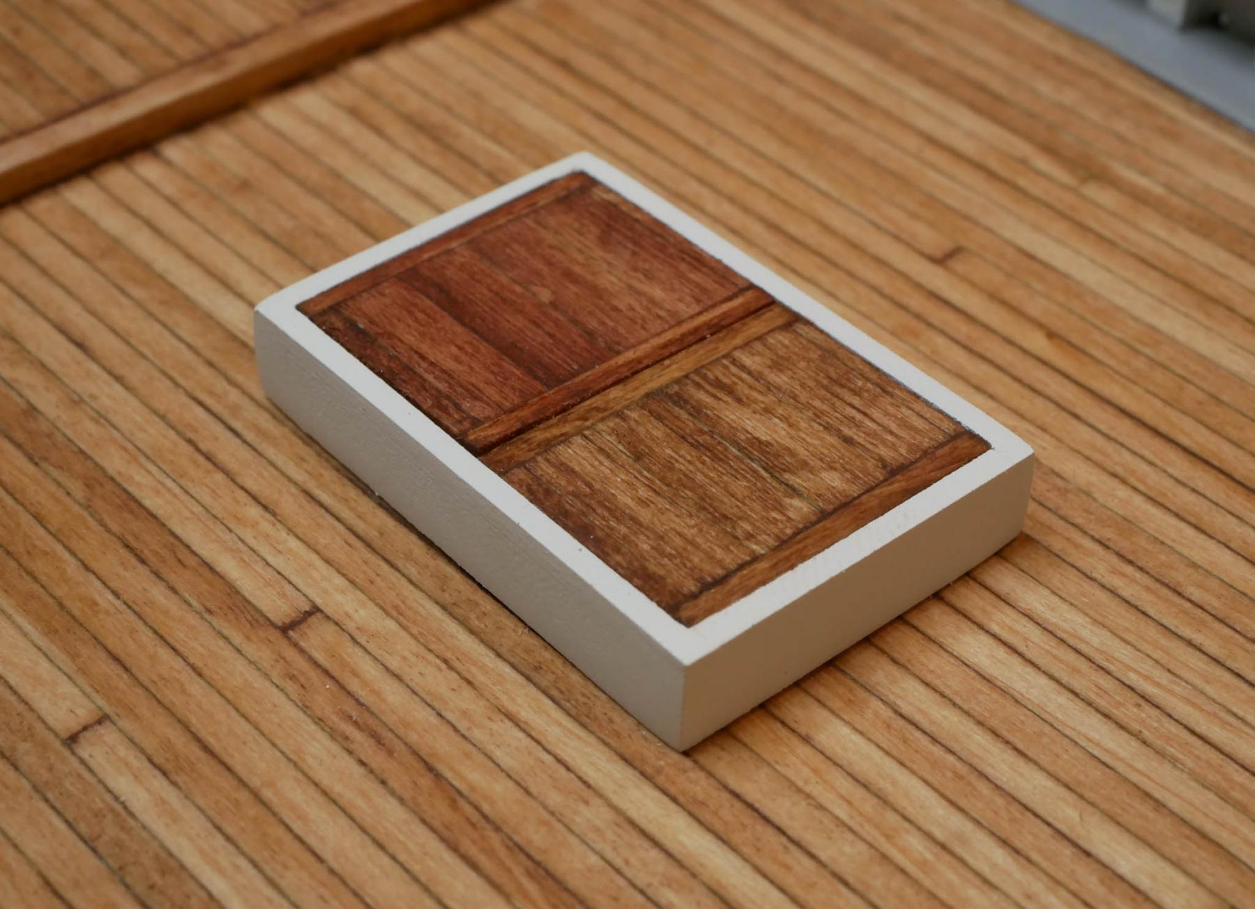
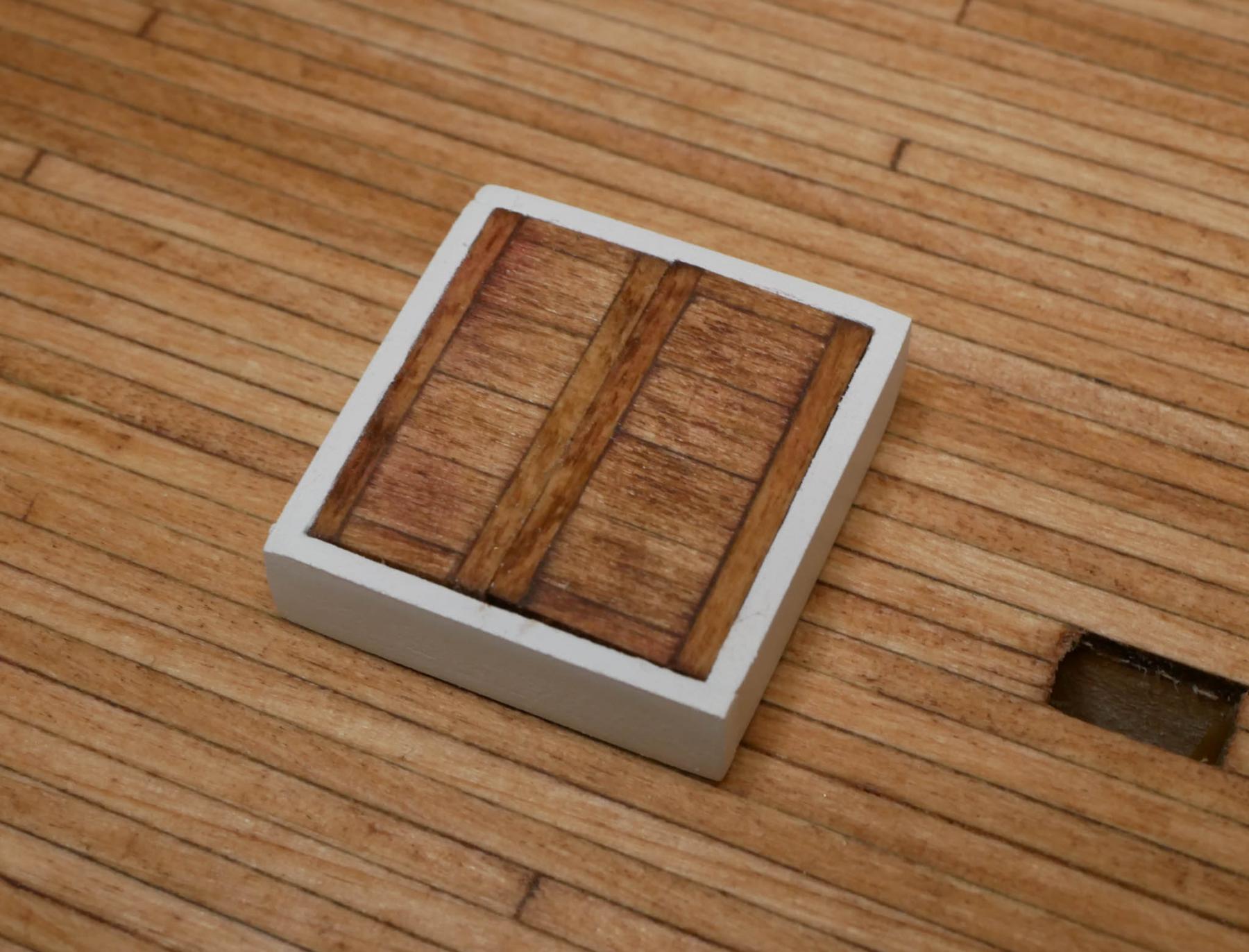
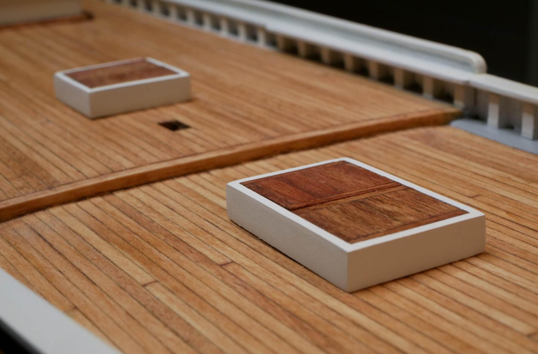
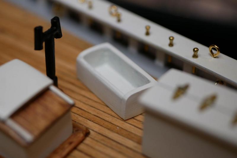
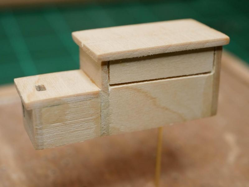
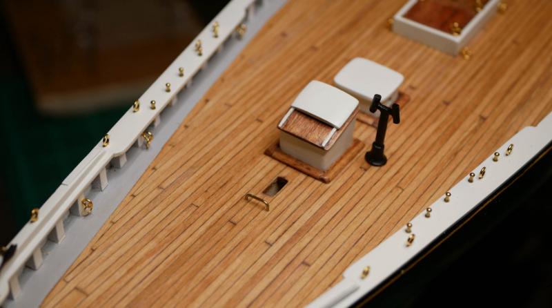
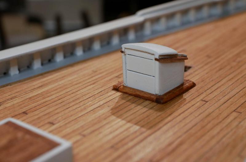
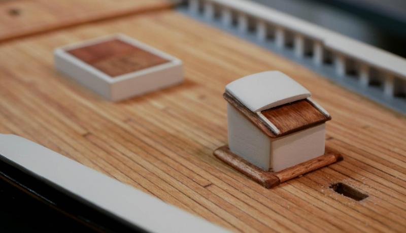
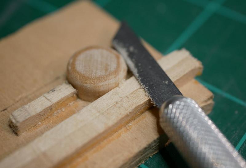
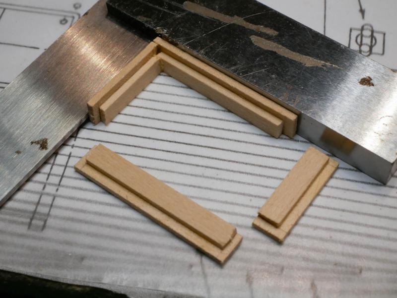
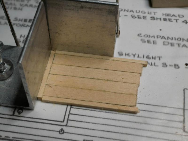
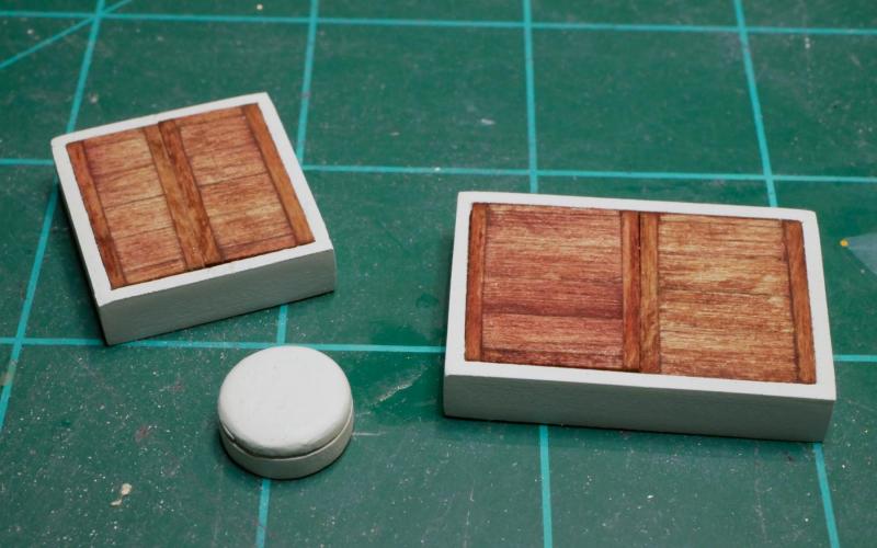
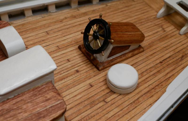
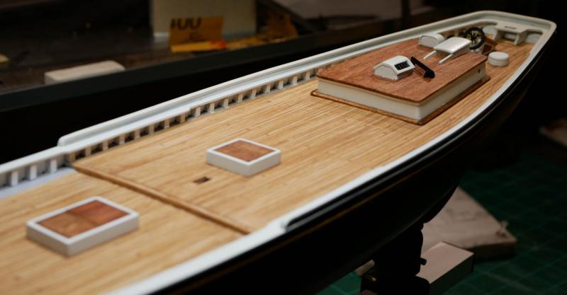
Unidentified Object and Cabins It would be great if I never had to work and could spend all my time on the build as I've done over the holiday weekend! I was able to knock out the 'unidentified object' and the two hatches pretty quickly. From the plans and old photos, the 'unidentified object' called for on the plans appears to be some kind of bin or storage container with a lid. I had a dowel rod on hand that was the right size, so I used that to make the object. I cut a piece of the rod to 5mm and rounded off the top. To create the seam for the lid, I used a small saw blade and cut into the piece as I rotated it. I used a piece of wood to keep the saw blade at a consistent height. I decided to build both hatches at once since they are identical except for their size. I had some wood strips that were the exact height of the sides, so I cut those to the right lengths for the sides of each hatch. I glued in some shorter pieces to create a ledge for the lids. The plans show the lids as solid pieces, two per hatch. Since I've been planking and staining the roofs of the deck structures, I decided I wanted to plank the lids as well. My first attempt was simple - I just cut some planks and filled in the lid. I wasn't happy with the results. It looked like a single planked piece, rather than two halves of a removable lid. I re-build the lids with a thin frame around the outside of each section. This took a few tries to get a process that worked well. I ended up building the entire lid for each hatch as a single piece, then cutting it in half and adding the inside frame sections. Everything was then sanded and painted. They ended up looking pretty good when placed on the deck. I haven't added any of the hardware yet - I'm going to add all the eyebolts/rings on the deck structures in one pass after I get them built (but before they are glued in place on the deck).


- 245 replies
-
- 9
-
-
- bluenose
- model shipways
- (and 1 more)