


bartley
-
Posts
424 -
Joined
-
Last visited
Reputation Activity
-

 bartley got a reaction from Matrim in Ripping Planks - what I've learned from others
Interesting Glenn,
When I innocently posted this photo in my log last year:
I got lots of PM's about how dangerous it was.
Here is one of my responses:
"Yes, You are correct. this is not the recommended way but many people use this technique and I am not an experienced user of table saws either so was a bit concerned . So I asked Jim Byrnes about this and he replied that ripping between the blade and the fence was the way to go . Apparently there is a very small offset at the rear of the fence to minimize the chances of kickback.
I used a block of wood on the left hand side behind the blade to push the billet against the fence and then used a push stick once the billet was on the table. There was no evidence of any kick back in the forty odd planks that I cut. Of course you don't need to move the fence if you do it this way and so I imagine the reproducibility is better. Incidentally, Chuck does it this way and he must have cut tens of thousands of planks."
John
-
 bartley got a reaction from Canute in Ripping Planks - what I've learned from others
Glenn,
A year ago I was new to table saws myself. If you read books or watch videos on the operation of full-sized table saws you will find that they all recommend that the safe way to avoid kickback is to cut thin strips on the outside of the blade. this was why I was concerned initially. but after the recommendations of Jim, Chuck and Jefff from HobbyMill I began doing the way you do it with some slight variations in the exact technique and have never had a problem. An important point is never yo but any sideways pressure on the back (exit end] of the blade. So for example a push stick must be pushed straight through with no sideways pressure.
John
-
bartley got a reaction from Canute in Ripping Planks - what I've learned from others
Interesting Glenn,
When I innocently posted this photo in my log last year:
I got lots of PM's about how dangerous it was.
Here is one of my responses:
"Yes, You are correct. this is not the recommended way but many people use this technique and I am not an experienced user of table saws either so was a bit concerned . So I asked Jim Byrnes about this and he replied that ripping between the blade and the fence was the way to go . Apparently there is a very small offset at the rear of the fence to minimize the chances of kickback.
I used a block of wood on the left hand side behind the blade to push the billet against the fence and then used a push stick once the billet was on the table. There was no evidence of any kick back in the forty odd planks that I cut. Of course you don't need to move the fence if you do it this way and so I imagine the reproducibility is better. Incidentally, Chuck does it this way and he must have cut tens of thousands of planks."
John
-
bartley got a reaction from Canute in Ripping Planks - what I've learned from others
With the longer stock all I find I need to do is to provide a bit more support at the end of a table. The problem is the longer plank tilts up as it goes off the end of the table. I just have a block of wood the same height as the table which supports the plank as it comes off the table.
John
-
 bartley got a reaction from mtaylor in Ripping Planks - what I've learned from others
Glenn,
A year ago I was new to table saws myself. If you read books or watch videos on the operation of full-sized table saws you will find that they all recommend that the safe way to avoid kickback is to cut thin strips on the outside of the blade. this was why I was concerned initially. but after the recommendations of Jim, Chuck and Jefff from HobbyMill I began doing the way you do it with some slight variations in the exact technique and have never had a problem. An important point is never yo but any sideways pressure on the back (exit end] of the blade. So for example a push stick must be pushed straight through with no sideways pressure.
John
-
bartley got a reaction from mtaylor in Ripping Planks - what I've learned from others
Interesting Glenn,
When I innocently posted this photo in my log last year:
I got lots of PM's about how dangerous it was.
Here is one of my responses:
"Yes, You are correct. this is not the recommended way but many people use this technique and I am not an experienced user of table saws either so was a bit concerned . So I asked Jim Byrnes about this and he replied that ripping between the blade and the fence was the way to go . Apparently there is a very small offset at the rear of the fence to minimize the chances of kickback.
I used a block of wood on the left hand side behind the blade to push the billet against the fence and then used a push stick once the billet was on the table. There was no evidence of any kick back in the forty odd planks that I cut. Of course you don't need to move the fence if you do it this way and so I imagine the reproducibility is better. Incidentally, Chuck does it this way and he must have cut tens of thousands of planks."
John
-
 bartley got a reaction from Ryland Craze in Ripping Planks - what I've learned from others
Interesting Glenn,
When I innocently posted this photo in my log last year:
I got lots of PM's about how dangerous it was.
Here is one of my responses:
"Yes, You are correct. this is not the recommended way but many people use this technique and I am not an experienced user of table saws either so was a bit concerned . So I asked Jim Byrnes about this and he replied that ripping between the blade and the fence was the way to go . Apparently there is a very small offset at the rear of the fence to minimize the chances of kickback.
I used a block of wood on the left hand side behind the blade to push the billet against the fence and then used a push stick once the billet was on the table. There was no evidence of any kick back in the forty odd planks that I cut. Of course you don't need to move the fence if you do it this way and so I imagine the reproducibility is better. Incidentally, Chuck does it this way and he must have cut tens of thousands of planks."
John
-
 bartley got a reaction from MEDDO in Ripping Planks - what I've learned from others
Interesting Glenn,
When I innocently posted this photo in my log last year:
I got lots of PM's about how dangerous it was.
Here is one of my responses:
"Yes, You are correct. this is not the recommended way but many people use this technique and I am not an experienced user of table saws either so was a bit concerned . So I asked Jim Byrnes about this and he replied that ripping between the blade and the fence was the way to go . Apparently there is a very small offset at the rear of the fence to minimize the chances of kickback.
I used a block of wood on the left hand side behind the blade to push the billet against the fence and then used a push stick once the billet was on the table. There was no evidence of any kick back in the forty odd planks that I cut. Of course you don't need to move the fence if you do it this way and so I imagine the reproducibility is better. Incidentally, Chuck does it this way and he must have cut tens of thousands of planks."
John
-
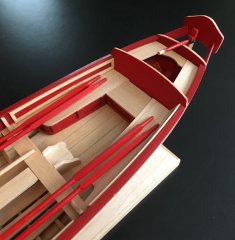
 bartley got a reaction from Vladimir_Wairoa in HM Cutter Cheerful 1806 by glbarlow - FINISHED - 1:48
Very impressive Glen. Have a look at mine at the same stage. Just lacks the crispness of yours doesn't it?
John
-
 bartley got a reaction from glbarlow in Ripping Planks - what I've learned from others
With the longer stock all I find I need to do is to provide a bit more support at the end of a table. The problem is the longer plank tilts up as it goes off the end of the table. I just have a block of wood the same height as the table which supports the plank as it comes off the table.
John
-
bartley got a reaction from mtaylor in Ripping Planks - what I've learned from others
With the longer stock all I find I need to do is to provide a bit more support at the end of a table. The problem is the longer plank tilts up as it goes off the end of the table. I just have a block of wood the same height as the table which supports the plank as it comes off the table.
John
-
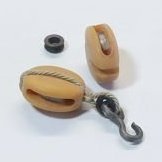
bartley reacted to Chuck in HM Cutter Cheerful 1806 by bartley - FINISHED - 1/48 scale
They look OK....the length wont affect things. But yes they are the typical funky shape for commercial ones being very bulbous on the tops. I am more worried about you not being able to get the rope coils over the top of those because they are so close together.
But it will probably be OK. I think you should use the longer ones. They are much better than the shorter ones.
-
 bartley got a reaction from GrandpaPhil in HM Cutter Cheerful 1806 by bartley - FINISHED - 1/48 scale
Post 32: The Winch
The winch was constructed as per the plans. The posts were made from 5.6 mm square stock (7/32) and the cross beam from 4.75 mm Square (3/16). The tops of the posts were shaped in a similar manner to that fused for the timber-heads (knife and needle file):
The roller was tuned on my homemade lathe to a diameter of 4 mm and the bolt heads were simulated with 24 ga blackened wire:
Micro-tubing was used for the winch handles.
John
-
bartley got a reaction from GrandpaPhil in HM Cutter Cheerful 1806 by bartley - FINISHED - 1/48 scale
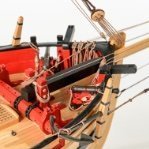
Post 33: Pin Rails
I have constructed the pin rails from 3/64 strip as suggested by Chuck. He makes his own pins from 3/64 square strip but I found that my skill s could not match his especially making 20 odd all the same! so I opted for commercial brass ones. Clearly they will need some further treatment - blackening, or maybe painting to llok like wood:
These fit tightly into a 1mm hole and seem to be about the correct scale. . Here I need some advice Chuck because they are only 8mm long and do not extend far below the pin rail. I have some 12 mm long ones but they need a 1.2 mm hole as you can see in this mock-up:
The tops also look a bit more "authentic". What do you think Chuck? I am worried about the consequences of the short ones when it comes to rigging them.
John
-
bartley got a reaction from glbarlow in HM Cutter Cheerful 1806 by bartley - FINISHED - 1/48 scale
Post 33: Pin Rails
I have constructed the pin rails from 3/64 strip as suggested by Chuck. He makes his own pins from 3/64 square strip but I found that my skill s could not match his especially making 20 odd all the same! so I opted for commercial brass ones. Clearly they will need some further treatment - blackening, or maybe painting to llok like wood:
These fit tightly into a 1mm hole and seem to be about the correct scale. . Here I need some advice Chuck because they are only 8mm long and do not extend far below the pin rail. I have some 12 mm long ones but they need a 1.2 mm hole as you can see in this mock-up:
The tops also look a bit more "authentic". What do you think Chuck? I am worried about the consequences of the short ones when it comes to rigging them.
John
-
 bartley got a reaction from JpR62 in HM Cutter Cheerful 1806 by bartley - FINISHED - 1/48 scale
Post 33: Pin Rails
I have constructed the pin rails from 3/64 strip as suggested by Chuck. He makes his own pins from 3/64 square strip but I found that my skill s could not match his especially making 20 odd all the same! so I opted for commercial brass ones. Clearly they will need some further treatment - blackening, or maybe painting to llok like wood:
These fit tightly into a 1mm hole and seem to be about the correct scale. . Here I need some advice Chuck because they are only 8mm long and do not extend far below the pin rail. I have some 12 mm long ones but they need a 1.2 mm hole as you can see in this mock-up:
The tops also look a bit more "authentic". What do you think Chuck? I am worried about the consequences of the short ones when it comes to rigging them.
John
-
 bartley got a reaction from Tigersteve in HM Cutter Cheerful 1806 by bartley - FINISHED - 1/48 scale
Post 32: The Winch
The winch was constructed as per the plans. The posts were made from 5.6 mm square stock (7/32) and the cross beam from 4.75 mm Square (3/16). The tops of the posts were shaped in a similar manner to that fused for the timber-heads (knife and needle file):
The roller was tuned on my homemade lathe to a diameter of 4 mm and the bolt heads were simulated with 24 ga blackened wire:
Micro-tubing was used for the winch handles.
John
-
bartley got a reaction from glbarlow in HM Cutter Cheerful 1806 by bartley - FINISHED - 1/48 scale
Post 32: The Winch
The winch was constructed as per the plans. The posts were made from 5.6 mm square stock (7/32) and the cross beam from 4.75 mm Square (3/16). The tops of the posts were shaped in a similar manner to that fused for the timber-heads (knife and needle file):
The roller was tuned on my homemade lathe to a diameter of 4 mm and the bolt heads were simulated with 24 ga blackened wire:
Micro-tubing was used for the winch handles.
John
-
bartley got a reaction from Ryland Craze in HM Cutter Cheerful 1806 by bartley - FINISHED - 1/48 scale
Post 32: The Winch
The winch was constructed as per the plans. The posts were made from 5.6 mm square stock (7/32) and the cross beam from 4.75 mm Square (3/16). The tops of the posts were shaped in a similar manner to that fused for the timber-heads (knife and needle file):
The roller was tuned on my homemade lathe to a diameter of 4 mm and the bolt heads were simulated with 24 ga blackened wire:
Micro-tubing was used for the winch handles.
John
-
 bartley got a reaction from Chuck in HM Cutter Cheerful 1806 by bartley - FINISHED - 1/48 scale
Post 32: The Winch
The winch was constructed as per the plans. The posts were made from 5.6 mm square stock (7/32) and the cross beam from 4.75 mm Square (3/16). The tops of the posts were shaped in a similar manner to that fused for the timber-heads (knife and needle file):
The roller was tuned on my homemade lathe to a diameter of 4 mm and the bolt heads were simulated with 24 ga blackened wire:
Micro-tubing was used for the winch handles.
John
-
bartley got a reaction from JpR62 in HM Cutter Cheerful 1806 by bartley - FINISHED - 1/48 scale
Post 32: The Winch
The winch was constructed as per the plans. The posts were made from 5.6 mm square stock (7/32) and the cross beam from 4.75 mm Square (3/16). The tops of the posts were shaped in a similar manner to that fused for the timber-heads (knife and needle file):
The roller was tuned on my homemade lathe to a diameter of 4 mm and the bolt heads were simulated with 24 ga blackened wire:
Micro-tubing was used for the winch handles.
John
-
bartley got a reaction from MEDDO in HM Cutter Cheerful 1806 by bartley - FINISHED - 1/48 scale
Post 32: The Winch
The winch was constructed as per the plans. The posts were made from 5.6 mm square stock (7/32) and the cross beam from 4.75 mm Square (3/16). The tops of the posts were shaped in a similar manner to that fused for the timber-heads (knife and needle file):
The roller was tuned on my homemade lathe to a diameter of 4 mm and the bolt heads were simulated with 24 ga blackened wire:
Micro-tubing was used for the winch handles.
John
-
bartley got a reaction from Canute in Blackening brass
You can buy burnished rings and eyepins, which are black but I have never seen anything "preblackened" in the sense we are talking about.
John
-
bartley got a reaction from mtaylor in Blackening brass
You can buy burnished rings and eyepins, which are black but I have never seen anything "preblackened" in the sense we are talking about.
John
-
bartley got a reaction from GrandpaPhil in HM Cutter Cheerful 1806 by bartley - FINISHED - 1/48 scale
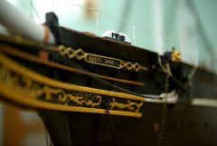
Post 31: Bowsprit
I am in the process of constructing the remaining deck furniture - Windlass etc. However, I decided to make and trial fit the bowsprit so that I can avoid maneuvering around the deck fittings. I turned this from 5/16 square stock as suggested by chuck. I drilled three 1.5 mm holes while the stock was still square and also the holes for the sheave at the tip
I then turned this on my home made "lathe"
The board at the end has a Roller Blade bearing. I actually have two of these and on longer jobs I position one about half way along to add extra support. I find this works pretty well and is cheap!
Of course I had to enlarge the hole in the bow to fit. Initially, I did this with drills of increasing diameter but this led to tearing of the timber so in the end I did most of the work with a round file. Here is the fitted bowsprit:
John