rraisley
-
Posts
80 -
Joined
-
Last visited
Content Type
Profiles
Forums
Gallery
Events
Everything posted by rraisley
-
How to Make Mast Straps
rraisley replied to rraisley's topic in Painting, finishing and weathering products and techniques
Keith Black's posted pic shows some fairly complex arrangements for attaching the spar to the mast. As mentioned previously, info I have indicates the Victory's upper 2 spars have roller-style Parrals, but mentions the lower spar has trusses. It's hard for me to imagine that while the upper two use complex Parrals, the lowest, heaviest spar uses a single rope wrapped around the mast (per Dr PR's drawing above). -
How to Make Mast Straps
rraisley replied to rraisley's topic in Painting, finishing and weathering products and techniques
Thanks for the diagram, Keith. I'm not sure how much applies to the Victory. The Parrals shown by Longridge have the rollers, rather than the types shown. I don't know if the Wooden Yokes would be used with that or not. And he says that Yokes, NOT Parrals were used on the lower mainsail yard, but the yokes in the diagram connect to parrals. Confusing. But the diagram is nevertheless very helpful and interesting. -
How to Make Mast Straps
rraisley replied to rraisley's topic in Painting, finishing and weathering products and techniques
Continuing on my Victor cross-section, I'm a bit unsure how the 3 spars are held to the mast. The kit shows no attachment except by blocks. Longridge has nice views of the Main and Topsail yards but not the Topgallant yard. The main mast appears supported by 2 sets of double/triple 26" blocks. A rope is shown around the mast, but no Parral is shown. The Topmast yard is held by a single 2" double type block, and a Parral is clearly shown. The Topgallant yard has nothing shown; the kit indicates two double blocks holding it. The Main yard show ropes looped around the mast and and supported by looping around the rectangular piece above the Top (sorry, don't know what it's called). But there is no block or adjustment in that line, so why the 2 blocks on either side? Longridge mentions the Topsail and Topgallant yards are held by Parrals, but refers to Trusses for the Main yard. What are the Trusses? Do ropes from the Parrals just loop 180 degrees around the yard on each side? (Seems they'd be attached more securely, like attached somehow or looped around a couple times, so the mast would not slide to the side.) Any further details or information on these areas would be appreciated. -
Thank you all, that helps a lot. A new phase of my education begins..... (at age77 😉
-
Does loose-footed refer to the movie Footloose? I'm sorry, Allan, you've been a fantastic help to me, but I don't know what you said. I don't have Lees book, just what I've mentioned (well, and Longridge). I've had to look up the terminology I've used so far, so perhaps I sounded more informed than I actually am. 🤪 Like when I met my wife's German great aunt and talked to her using my high-school German. I could pronounce it fine, but had no idea what she spoke back to me.
-
I'm modeling Corel's HMS Victory cross-section, so obviously rigging details are limited. The plans, as well as drawings in McKay, show the stunsail booms hanging below the Main Yard and the Main Topmast Yard, but not the Main Topgallant Yard. Alan McGowan in the stunsail diagrams show a boom, of sorts, at both the top and bottom of all the stunsails, and there are stunsails hanging from all three yards. It kind of makes sense that one (the lower) boom (not sure the terminology for that) would be wrapped with the stunsail itself. And I realize this is a simplified model without sails, so running rigging and anything pertaining to the sails is somewhat modified or limited. But the Main Topgallant Yard would appear to require some boom at the top, like the other lower 2 booms, and I don't see a drawing showing them. So, should the Main Topgallant Yard have stunsail booms too? Or would those stunsails have upper and lower booms included with the stunsails themselves, and therefore not shown?
-
How to Make Mast Straps
rraisley replied to rraisley's topic in Painting, finishing and weathering products and techniques
Very nice work! What is plaricard? -
That is, the metal bands or straps around a wooden multi-piece lower mast, as on the lower masts of the Victory cross-section I am making. I assumed I'd use 1/16" tape for it, so got some in matt black to put on after painting. As my mast is a fairly tight fit through the 5 decks, I was going to use the tape as masking tape for lower decks over black paint, then paint the mast yellow orchre, remove the tape masking and add it permanently for the remainder of the mast, clearing over if required. Seemed like a good idea. I sprayed the bottom of the mask flat black today, and found that the tape I got won't stick to it. Turns out it's graphic tape, not auto pinstriping tape, and is less adhesive. So now I'm looking for pinstriping tape, but I'm doubting whether it will stick well enough either. Some say it has to be on a glossy paint, not flat, in which case I'd have to gloss clear the yellow orchre, apply the tape, then dullcoat it. Longridge suggests copper shim cut to size. But that's for 1:48 scale, and his gluing neatness is probably better than mine. (Actually, he describes butting the copper and silver soldering them - he is definitely in a different quality camp than I.) He describes them as 4.5" x .5" iron, spaced every 3.5 feet, although his number of bands doesn't seem to check per the drawing. What have you all done on similarly scaled ships (1:98)?
-
Anyone? So far, I'm leaning towards black, as there are other black details on the quarterdeck, white doesn't seem to look right, and wood/stain is unprotected. But I'd prefer to be accurate.
-
Another question on painting the Victory: What color should the exposed cross beams be in the open area in the central quarterdeck under the small boats? On the few models I've seen painted in this area, one had black beams and members surrounding the opening, one was all yellow ochre. Videos I've seen of the Victory have this area covered with a fitted tarp, so I can't tell. In the non-open areas of the quarterdeck floor supports (the "ceiling" of the upper gun deck), the beams and underside of the decking are white, while the outer walls of this deck only were yellow ochre. Seems funny that the beams under the quarterdeck, painted white everywhere else, would not be white in the open area, but I don't know.
-
Thanks for your thoughts. As to the step color, I've seen it done both ways: All steps black, or steps colored the same as the stripes they're in. You're right about no strain on them, of course. I'll probably muck up the painted surfaces with extra glue, but that could be touched up I think.
-
I'm building Corel's 1:98 scale Victory cross section. I've got the basic hull section complete (unfinished) with all inside detail and painting complete, except the upper gun deck details and top deck and details. I've painted and finished the decks and details on them before putting the next deck in place, because I can't really work on them once they're covered, and that's worked pretty well. I haven't touched the outside yet, however, except for planking. My question is: When do I paint the sides (black & yellow ochre stripes) in particular? They'd be easiest before gluing on all those steps, on both sides. I could easily mask and get nice straight lines. But then I'd be gluing the steps to painted areas, which isn't ideal, and touching it all up afterwards. OTOH, if I glue all the steps and such on, there's no way I'll be able to mask straight lines for painting the black and yellow stripes. With a full model rather than a cross-section, masking would be the way to go, because there's so much more of it than at the steps. But this little cross section is half steps, and presents a very different challenge What would you do? What have you done in similar situations?
-
I think that's a good decision. I've always stained my decks to the dark side, just liking the look of them. But looking at photos of tall ships, including the Victory, the decks, while clean, have a very sun-bleached and natural look to them. Yours look fine. In fact, if you use a sealer, I'd make sure it's a matt finish; you just don't see shiney decks on old ships.
-
It's disturbing to see details roughed out by hand looking better than I could do with a lathe or purchased item. Definitely disturbing.😾
- 950 replies
-
- 3
-

-
- syren
- model shipways
- (and 1 more)
-
Model Shipways USS Constitution Cross Section
rraisley replied to Jorge Hedges's topic in Wood ship model kits
Sorry. My /extremely/ bad. Guess I read "cross section" and slipped a gear. -
3D drawings 18pdr at 1/64 scale
rraisley replied to Barbossa's topic in CAD and 3D Modelling/Drafting Plans with Software
If you're interested in Armstrong pattern guns, this site will show scaled drawings for any size you like: http://arc.id.au/ArmstrongPattern.html I have Fusion 360 models for Victory's 32, 24 and 12-pounders. One could be modified to get the 18 pounder. I also have a model made from Hahn's standard plans, which could possibly produce an 18-pounder of that design. Are you looking for 2D plans to turn a model on a lathe, or a 3D STL model to make using a 3D printer? -
I've been working with Fusion 360 for a few months now, and am able to model many things fairly well. My son has 2 filament printers and one resin printer, but in printing guns for my 1:98 Victory cross section, has had a lot of problems. MANY failures in resin printing, replacing several film vat bottoms (or whatever they're called) and failed objects. Finally got enough to work for the model. Now he's tried a desktop size barrel, which also failed, and he's basically given up on them for me. All HIS stuff works great, but very few on mine. One problem I've had with the STL files created by Fusion 360 is that some components come out hollow, while others are solid. For example, on the barrel, the main barrel was solid, the trunnion and gunlock hollow. On my gun carriage, the sides and axtrees were solid, while some other parts were hollow. I could only confirm a solid model by starting with one solid part, then JOIN another part to it, making the combination solid, and doing that for every piece in the assembly, which was a real pain.
-
Model Shipways USS Constitution Cross Section
rraisley replied to Jorge Hedges's topic in Wood ship model kits
I assume you're aware of the series of videos on the model? -
In the case of the Victory, pig iron blocks were laid between framing members, criss-crossing layers, then covered with pebbles/gravel/small stones. Certainly the pig iron would not move, and the stones had barrels and other items on them, usually held in place by ropes and such. I've included this "feature" in my Victory cross-section, while most similar models just show a bunch of (heavy) stones. I would think that Victory would not be the only warship to use pig iron, although also imagine that it was expensive and possibly not used on commercial ships. http://margaretmuirauthor.blogspot.com/2012/11/hms-victorys-ballast-pig-iron-and.html
-
Question regarding the base of the mast
rraisley replied to DaveBaxt's topic in Masting, rigging and sails
I just now tried wrapping some large, soft thread around the mast with wax paper covering it so it doesn't stick, forming the general shape, then puttied in with white glue. Probably paint it a canvas or gray color when done. Making a ring that fits well to the mast, flat to the deck (a temp piece of wood with the right size hole subs for it now, again with wax paper). If it looks okay, I'll put the "ring" in place on final mast install, and think it will be a decent effect. -
Question regarding the base of the mast
rraisley replied to DaveBaxt's topic in Masting, rigging and sails
I've been meaning to ask about mast coats myself. My Victory cross-section includes nothing, and I'd always felt there had to be /something/ to keep it solid and prevent leaks. McKay's books show relative size and shape, but as I'd also read they were covered with waterproof fabric, wasn't sure how best to model them. The wedges shown above make a lot of sense; I assume that area was just then covered with fabric. On my model, adding such a device should help finish it off better, as well as help secure the mast. I was considering using some bent soft wire, even solder, then puttying around it to make the shape more correct. Probably attach it to the mast and deck the last time the mast is positioned and glued in place. -
Using the 3D models I've made for Victory's guns, in addition to making them in resin for my 1:98 scale Victory cross section, I intend to make larger desktop models of the 32- and 12-pounders. My original thought was to simply mount the two on a single cherry stand, facing each other at an angle. This would require no rigging blocks or breech line, as there's nothing to attach them to. But I'm also considering mounting each against a small wall section, in which case they would require blocks and such. Does anyone know of a source for larger scale blocks? At this point, I'm doing them in 1:18 scale. I think I remember the 32-pounder's double blocks were 11" long, but can't remember the source, with the single and doubles on the 12-pounder being about 8". That would make the blocks about 11-15mm in size, quite a bit larger than the largest I've seen advertised (around 1/4" or 6.35 mm). I could make them, but if I do, I'll probably make them using a 3D model and 3D printer, so I'd need drawings of them, if anyone has a source. Anyhow, any ideas?
-
So, I'm not only not sure what to call it, but also where to post this. Mods, feel free to move to another forum. I'm looking at ways to support the 1:98 scale HMS Victory cross section model I've been working on, and am considering some kind of simplified wood "building support or ways" or "dry dock" made of scale lumber, such as might have been used during construction of the vessel, or possibly for repairs in dry dock. I know a "real" dry dock would be impossibly large and not add to the model, but have seen some simplified examples, mostly on imported models from China, that look pretty good, something like this: I doubt this is at all accurate: for one thing, the side braces don't appear that they are at a sufficient angle to stay in place and support the ship. But - it looks pretty good. Anyhow, an Internet search as well as a search here found nothing I can really use. Does anyone have any ideas or information on how to construct something on this order, preferably something reasonable, if not completely accurate? I'd prefer this to the suggested screws into the keel mounted to the round base or columns. This, I can adapt to the hull and be sure at least it's standing vertically; screws will, I know, just tilt the model to the side, and possibly skewer something critical in the process.
-
The OP's drawing appears to me to be the equivalent of a Patent Application, between Nueva Invención and the format, so may never have been done, at least exactly like the drawing. I don't understand Spanish so can't tell more.
-
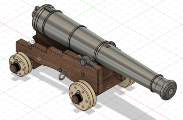
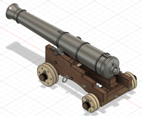
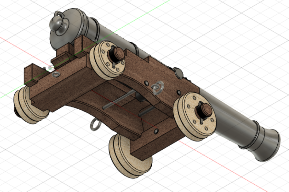
I've completed modeling of the 12-Pounder gun, based on Longridge, Bugler & McKay, as well as Blomefield for barrel dimensions. All sources in this case agree very well. Here are some 3D pics. I'll attach a 1:24 scale 3-View as well, and some other scales, in PDF format. Let me know if you want anything additional. 12-Pounder Views 1-24 Final.pdf 12-Pounder Views 1-48.pdf 12-Pounder Views 1-98.pdf 12-Pounder Views 1-24.pdf