HOLIDAY DONATION DRIVE - SUPPORT MSW - DO YOUR PART TO KEEP THIS GREAT FORUM GOING! (Only 36 donations so far out of 49,000 members - C'mon guys!)
×


Modeler12
-
Posts
1,716 -
Joined
-
Last visited
Content Type
Profiles
Forums
Gallery
Events
Everything posted by Modeler12
-
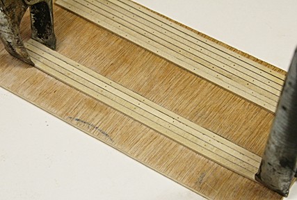
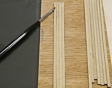
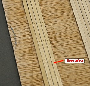
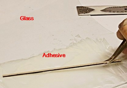
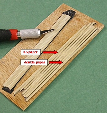
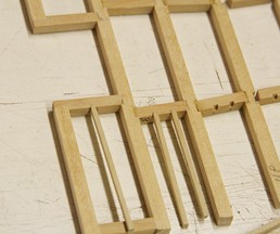
 I know I jump around a lot, but here is another subject that got my attention. Deck planking and its caulking. I was not aware that others here had used black paper on the edges of deck beams to simulate the caulking. Bob Hunt had suggested using a black marking pen to coat one edge and that is what I used on the deck planks of the 'mother' model. But they did not show well and were not clearly defined. So, I had to try black paper (and at this point I don't care if it is black or dark brown). My first tries involved spraying contact cement on the paper, etc. It worked but the ends tended to come loose. Next I used carpenters glue (the yellow stuff), but I have always had trouble getting a nice even coat on narrow parts. This time I used a piece of old glass and a steel ruler to smear a thin coat of glue that I could then use to dip the edges of the planks. It worked a lot better as shown below. The picture below shows some planks that I used in my first experiment, but look at the four planks to the left. The paper I used was .010 inch thick which would result in a line too thick (0.75 inch real). Others suggested to use thin tissue paper, but that becomes a real mess (especially when you try to coat it with adhesive). After I made some planks with my paper and the glue was set, I used some 1000 grid paper to sand the black paper. Low and behold, the paper is layered and the 'sanding' resulted in removing one of those layers. I don't know how much, but at least the thickness has been reduced enough to give the edge a decent 'caulking'. Notice in the picture below, however, that the edge of the plank has to be very smooth, otherwise the black shows 'dents' or imperfections. Then again, that may not be all that bad in real life.
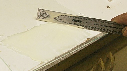
- 572 replies
-
- 8
-

-
- constitution
- frigate
- (and 1 more)
-
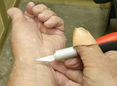
When I use a new blade I always take a test cut to be sure it is sharp enough.
-
There probably are several ways to show the caulking between deck planks. I have used a black marking pen, but found that it had a tendency to go over the edge. No problem, because the sanding afterwards took care of a lot (but not all). Then I read here some where that someone used black paper between the planks. But how? Here is my approach: Take a section of black paper (available at office supply centers), spray some contact cement on it, and position the planks on edge. Press well and let it set overnight or so. Then cut them apart, do a little sanding on the edges and fit them together. Below I show the results of my experiment.
-
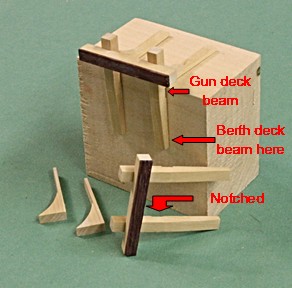
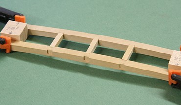
Here are two more pieces that I decided to make in advance. They are the riding bits on the gun deck, used to hold the anchor cables. I thought it would be important that they would fit both the gun deck beam and the berth deck beam when finally installed. The knees (not too clear in the assembled picture) rest on top of a long 'plank' or support that straddles three beams. I will also add some bolts at various locations and then it should fit in place when the gun deck beams are all in place. It is a good thing I did this, because a trial fit showed that two of the carlings on the berth deck would be right underneath the vertical posts. It was a simple matter of moving those carlings just a bit further out.
- 572 replies
-
- 7
-
-
- constitution
- frigate
- (and 1 more)
-
You know Mark, I might even wire this thing with a couple LEDs so there will be a real light in the light room. Otherwise no one will understand what this is all about. I have done this previously with a couple windmills I made some years ago and, if nothing else, it makes an interesting night light.
- 572 replies
-
- 6
-
-
- constitution
- frigate
- (and 1 more)
-
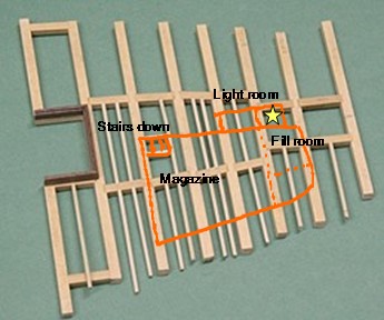
A few comments about the powder room. Reading a few descriptions and 'the book', I have come to the following conclusions about the forward powder room, the place where kegs of powder were stored and the cartridges were filled. The room is enclosed entirely to prevent moisture from entering during the filling process. I show it roughly below. The magazine and fill room are below the orlop deck and accessible through the hatch as shown. This is where the kegs would go through, but when the open powder was used this scuttle would be closed off. There is another scuttle just forward of the fore-mast and that is where the crew would go to deliver the cartridges to the gun deck (scuttle is beyond my model). A door in the wall would provide access to this scuttle. The light room would not be part of the powder room and windows would let light through to the tub of gun powder so the young men working there would have some light. The light room would be reached from above (the orlop deck). I need to prepare detailed drawings yet, but I think this is pretty close to what the powder room would look like. Since this is the lowest part of the ship, I will show as much detail as I can, even though my intent is still to have the structural parts be emphasized along the starboard side. For example, the orlop beams and carlings would only show on one side while the deck planking, sail-room, carpenter's walk etc. would be complete on the port side. That is why I did not include the ledges along the port side.
- 572 replies
-
- 7
-
-
- constitution
- frigate
- (and 1 more)
-
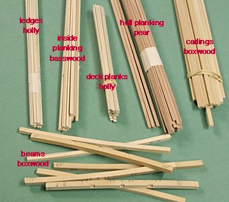
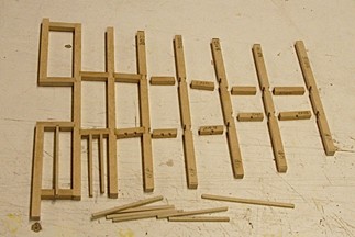
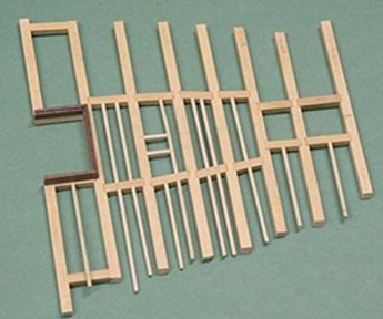
Update: I have been busy cutting strips of wood for the various locations. The picture below shows some and the kind of wood I am using where. Earlier I showed a couple of beams and how they influence the size and location of the hatches. But there is more to this and I will go into that later. I started with the frame-work of the orlop deck, the lowest deck. Again I am taking some liberties since the 'plans' in the book don't go into a lot of details. For example, I decided that since this deck is well below the waterline and should not get 'wet', there is no reason for the beams and deck to have sideways curvature. I am making mine flat except for some curvature towards the bow. You may notice the one opening for the 'scuttle' or opening from the orlop deck down to the powder room. I will have more about that lower portion of the ship when I show what I want to do with the powder room. I also decided to add not only the carlings but the ledges as well. They are all fitted into slots cut on my mill. By way of perspective: the ledges are 0.060 x 0.080 inch (4.5 x 6.0 inch full scale). You might say 'why not square?' It turns out that the slabs of holly I used was 1/16 inch thick. And anyway, in my opinion, ledges should be narrow and deep if they are going to carry any weight. The whole idea here is to do as much 'bench-work' as possible. Later when I am ready to install this there will be a template and the sides will be cut to match. Hence, the beams and ledges along the side will be trimmed and fitted. Not to belabour (belabor) the points about gratings and hatches, but you might notice the hatch frames to the left. The actual hatch is wider in the aft direction (left) because this is also the area where the anchor ropes come down and are stored further aft. This will not be included, but I think a piece of rope will show the idea much further downstream in this project.
- 572 replies
-
- 7
-
-
- constitution
- frigate
- (and 1 more)
-
Perhaps I am missing something in what Dan suggested about the planking width and starting at both top and bottom and see how it turns out when they meet. It would seem to me (and that worked for me) that after dividing the sections with the battens, you measure the distance between the battens along the outside (not along the frames). Then you can calculate how wide the planks should be before they are beveled, etc. If any adjustments need to be made it is easier to do that with the last three or four planks as you work down towards the batten. You could even make minor adjustments to the location of the battens (up or down).
-
The book also shows four grates across the beam. But each one is therefore much wider. In particular the one next to the stairs. However the next one has only two very wide gratings (with the central 'beam' going the full length. But then again he does not show the grating per sec, only the opening of the hatch. In his foreword, Marquardt mentions the various refits and the shortfalls taken during the time since 1812. He also refers to the plans for redoing the ship to the 1812 plans. I get the impression that his book depicts that era. So, perhaps the grating he shows is indeed from 1812. Having said that, I still find several areas where he is not consistent and apparently relied on drawings provided by other sources. The spacing of the beams and support posts in one example. In defense of Marquardt I should say that despite a few 'hickups' I appreciate the effort he went to in putting this book together. If it had not been for all the details he shows, I would never had to guts to start this build.
- 572 replies
-
- 3
-
-
- constitution
- frigate
- (and 1 more)
-
Thanks George, Below is a picture of the ship in Boston. Notice towards the bow that the fife rail sticks out to the left beyond the width of the main hatch. The book's drawing on page 71 is not anywhere close to that. It is too wide, unless the drawings depict an earlier version. At least this makes me feel better.
- 572 replies
-
- 7
-
-
- constitution
- frigate
- (and 1 more)
-
Here is my fallback position. The grating once installed do show the round holes, but the spacing is much better than I can get with slats. Keep in mind that the width and length of the grating is dictated by the thickness of the frames into which they fit and that is determined by the spacing of the beams. Thus the frame has to be located such that the hatch opening lines up with the beams and carlings underneath. That will show in great detail when I start putting the open frame work together. There is another 'discrepancy' between the full model drawings and Marquardt's book (page 71). The hatch and slats above the stove should also line up with the beams. Marquardt seems to have it right whereas the model plans has this grating too short. Below is my version (including the brass screws for the planks). The chimney will sit on top of these planks. Then there is another 'difference' on the same book page. The large frame and grating are much wider than the model plans. Since I am building this model to correspond to the full size model, I have opted to make the narrower frame.
- 572 replies
-
- 7
-
-
- constitution
- frigate
- (and 1 more)
-
Furthermore, a word about 'strain' and 'stress' and 'force'. Even on Saturn strain is not measured with a force gage. Strain (in engineering terms) is a measure of the deformation or elongation of a material when a force is applied. Material don't break because of 'too much strain', they break when to much force is applied and the maximum stress level is exceeded. Stress being force divided by the cross sectional area of that part. People will break down under too much stress (not strain). Strain is simply the result of too much stress. It leads to wrinkles and other permanent markings. I know this is boring but I am sure any engineer will cringe when those three terms are always mixed up.
- 396 replies
-
- 4
-
-
- Idea
- Bright Idea
- (and 1 more)
-
A word about needle threaders. They are fine if the hole you want the line to go through is big enough. However, if you are using the tiny blocks for rigging the hole is just about the diameter of the line. That means it is impossible to pull the doubled line plus wire through. Rigging the blocks for a cannon is one example. I have given up on needle threaders a long time ago. Instead I put a tiny drop of CA glue on the end of the line and smear it along for about 1/2 inch. It only takes ten seconds or so and you can clip the stiff end of the line at an angle to give it some body and a point. It should slip right through.
- 396 replies
-
- 8
-
-
- Idea
- Bright Idea
- (and 1 more)
-
Mark, If I were to cut slats (which I am not doing), I would need a blade that is also 0.032 inch wide (which I don't have). I don't want to buy such a blade for the two pieces of grating I need. Hence I am using the method I describe above. If I had to make a lot of grating of the same dimensions I might give the slat approach another try. But not now.
- 572 replies
-
- 1
-
-
- constitution
- frigate
- (and 1 more)
-
Let me understand what you mentioned, Mark. The width of the lath has to be the hole size, but should also be not more than 2.5 inches square. For a model at 1:76 scale that means that the slats would be equal to or less than 2.5/76 = .033 inches. To make gratings by the 'usual' technique of cutting slats and slots with those dimensions would be tricky, to say the least. I can cut slots in a piece of wood that are 1/32 inch apart but when I try to slice them off the 'log' I end up with a lot of scrap. My point is that the width of the slot (and the slat) are just a function of the opening you have to work with and that they can be varied as long as you can live with a round hole (which is barely visible at the smaller scales). BTW can you show me an example of grating made with 1/32 inch square pieces? Perhaps Jeff did, but I wonder if anyone else can do the same. It still leaves the question about fitting them to the space we have to work with (dimension A in my case).
- 572 replies
-
- 2
-
-
- constitution
- frigate
- (and 1 more)
-
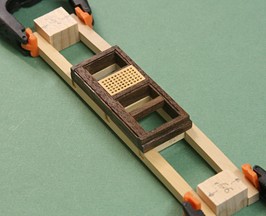
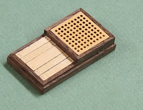
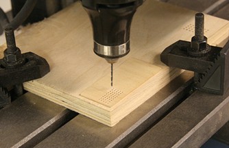
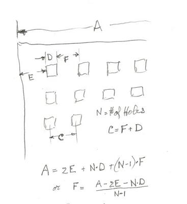
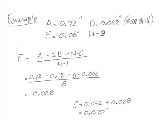
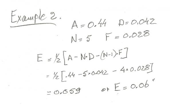
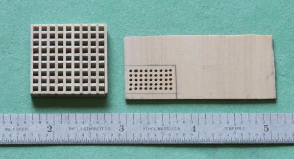
Gratings - my approach to custom sizes. Jumping ahead and doing a bit more planning, I came across two places where I need some grating. The parts that came with the kit were cut using lasers. I don't have one, so how do I make the grating? The space that I have to work with is 0.72 x 0.44 inches. When I tried to use the commercially available grating they just looked to gross and would not fit the above. The picture below shows one such that would have openings (full size) that would be about 6.4 inches across. A picture of the USS Constitution shows the grating to be about 1/2 that amount. What I did was to drill small holes evenly spaced and let it go at that (for now). Here is the set-up on my mill and the first crack at it. I might add here that I tried to make the holes square by using a tiny file and even a special square pick, but that just did not work. The holes are too small for filing. The square pick does not remove material; it just forces the fibers aside (which caused the parts to break). I even tried to make a broach by filing notches in the edges of the pick. Again not much luck there. Now for some math: Let's say you have an opening that is known in one direction, dimension A. You want the holes, D, to be about .04 inch diameter. You want a border, E, to be reasonably small. What would be the spacing? The rough sketch below shows the formulas that are involved. What I am after is the spacing, C. The second and third sketches show the calculations after I picked some numbers for the hole size and edge conditions. After some juggling with these dimensions, I arrived at something I could work with. The results of this led me to make the first prototype. The upshot is that you can make gratings with very small holes that maybe are not square but at least look more reasonable in size. It gives me a way out for this model.
- 572 replies
-
- 2
-
-
- constitution
- frigate
- (and 1 more)
-
Are you sure it was not 'Always Add Aqua'???
-
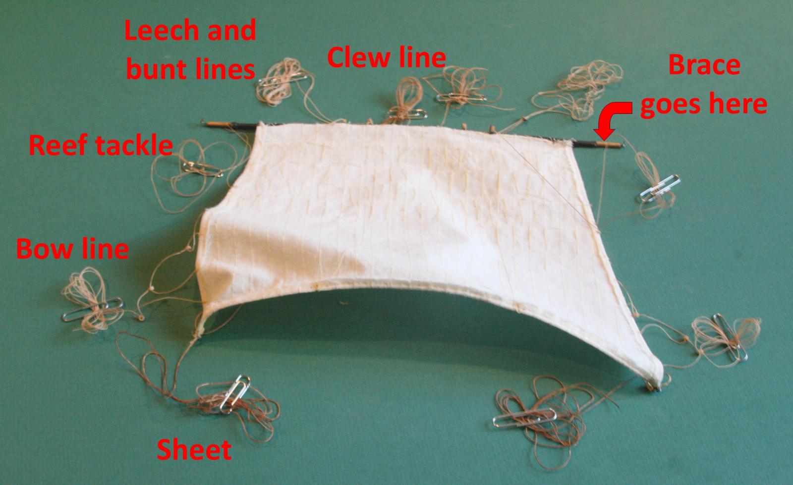
Chuck's point is well taken. First of all, though, is you. What do you think will be the main features you like? If it sails you want, be ready for a lot of work. If the cannons are very important as a 'whow', then concentrate on those more. I personally liked doing the rigging with lots of details on the various lines that operate the ship. I not only learned what they were all about, but it was a challenge to put them all together (with mistakes and several re-does). Then when it came to doing both sides of the ship the same, I 'cheated' because I was going to have the ship against a wall. So I used that side to 'experiment'. That was for the hull as well as those lines not too visible from the front view. To give you an idea of what the sails on my USS Constitution took to make, here is a picture of one of those topsails and all the lines that go with it.

- 55 replies
-
- 12
-
-
First time rigging - being organized
Modeler12 replied to RichardG's topic in Masting, rigging and sails
Your idea of making a data base/list is good. But I would encourage you to think/learn what each of those lines is used for. Petersson's book is great with lots of drawings that show how each element belongs on a ship. But again think of what and why a shroud is where it is and what its function is. I would right away separate all those 'ropes' by function: Standing vs Running; Keeping the masts in position; hoisting and lowering sails; setting the sails (and spars) in the right direction, etc. The terminology is new and not easily understood and learned, but it makes things a lot easier if you know the terms and what they mean. When someone here mentions a 'leechline', do you know what it is? -
I am sure you are the 'expert' on frames and how to correct mistakes. I may ask for your help pretty soon, dear friend. But first let me plug along and see how far I get. I am using a band-saw with a fine blade to cut the contours, and I am leaving a bit more on both edges for the final sanding. I could tilt the table of the saw but that gets to be complicated as well. So, we try and try again.
- 572 replies
-
- 2
-
-
- constitution
- frigate
- (and 1 more)
-
Thanks Steve. I thought maybe you were going to ask me what I was doing with the 'Goonsquad'. What I meant was the 'Geeksquad'. That is a company here in the US with all these bright geeks who can fix computer problems. In my case it was all done on-line, but they also have VWs running around fixing hardware problems. Great service. Their charge was a lot less than the 5 Gs it would have cost me with the goonsquad.
- 572 replies
-
- 4
-
-
- constitution
- frigate
- (and 1 more)
-
Thanks George. I sent the IP adress and we will see what happens next. Just on the side. I happen to be having other problems and contacted the Goonsquad. Besides fixing a bunch of problems, the tech spent at least half an hour this morning trying to figure out how he could solve the picture posting problem. Of course, we both realized that it was not my computer but the firewall at the web site. Now all of sudden it works. Here is the picture I tried to include in my last message on the page before. It shows the difference between the first and last frame sets.

- 572 replies
-
- 9
-
-
- constitution
- frigate
- (and 1 more)
-
To continue with my model building: Cutting the frame sets is taking a long time. One of the difficulties is that each frame has a slightly different shape. For example, below I show the first and l5th frame sets. The first ten or so are not too bad, but the further I get to the bow, the more I have to allow for the taper. (I tried to insert a picture here and it did not work. I get a black stripe with the Sucuri firewall emblem) For the time being, I am inserting spacers near the top. When those all look decent, I'll go ahead and glue the frames to the keel/keelson. (this one worked???)

- 572 replies
-
- 8
-
-
- constitution
- frigate
- (and 1 more)
-
You are right again. I didn' t know that there were so many forums on the web. Despite the warning I get, I will probe the model ship builder site. Thanks for steering me on the right course.
- 572 replies
-
- 2
-
-
- constitution
- frigate
- (and 1 more)
-
Wayne, that is probably because you are already a member. But go to http://www.shipmodeling.net/vb_forum/new_application.html and then the link at the bottom of that 'register' page. If I provide honest answers it would be very easy for anyone to find my home address and other details that I rather keep to myself. Why would they want to know where I live and how old I am?
- 572 replies
-
- 2
-
-
- constitution
- frigate
- (and 1 more)