Modeler12
-
Posts
1,716 -
Joined
-
Last visited
Content Type
Profiles
Forums
Gallery
Events
Everything posted by Modeler12
-
 A couple comments: Wayne, I really have to digest all the details you present above. Much appreciated, my friend. One quick check on the distance between ports shows that the plans are fine on the gun deck. It is exactly what I came up with. However, it does not jibe on the spar deck. George, I was not aware of the adjustments made by Lankford, but even at that the width of the gun ports should still have come out to be the same for the two decks. It has been my understanding all along that the gun ports were laid out such that they fitted between the frames. If the gun deck ports are right, then the spar deck ports would have to be the same or different by one frame (and they are not). The difference in the scaling factor is so slight that it would not account for the above. Meanwhile I have decided to redo the plans of the frames. Instead of the eleven I had counted on, there will be fifteen of the 'correct' thickness. Thus 15 inches "real" divided by 76.1 equals 0.197 inch for my model. All of this unless Wayne's info disputes this also. Steve, I am giving myself the benefit of my doubts and that leads to lots of confusion and also lots of extra work.
- 572 replies
-
- 3
-

-
- constitution
- frigate
- (and 1 more)
-
The question about the 'discrepancy' in the frame thickness and spacing continued to bother me. So, I did a little more digging and came up with the following: Perhaps the drawings supplied by Model Shipways in their kit are not correct. All along I have been using those drawings with virtually no problems. However, the width of the spar deck gun ports seem to be in error. The gun ports on the gun deck are wider than those above - they should all be the same width. The spacing also needs to be addressed since that screwed up the alignment with the frames. If my reasoning is correct then my apologies to Mr. Marquardt for suggesting that his drawings were at fault. Per Marquardt's drawings the frames are actually 15 inches wide and the gun ports about 45 inches. That is three frames, OK. If I use that for all gun ports, and the correct spacing of each, the 15 inches come out fine. That means that two frames together would be 0.395 inches thick for my model. That is a lot, and I am so far along in my layout that I may forego making new frames. However, I will use the same width for all gun ports in this section (and ignore what I have on the full model). I certainly don't want to correct those I would certainly suggest to those who are just starting the kit to at least consider what I mentioned here. To make all gun-ports the same width should not be a big deal.
- 572 replies
-
- 2
-
-
- constitution
- frigate
- (and 1 more)
-
I need to clarify this. Jason is not taking over Hobby Mill. He is an new company and gets help from Jeff as needed. It simply implies that Jason (who started his venture before Jeff's retirement) is going to fill a void and I wish him good luck with all of our wood business.
- 572 replies
-
- 3
-
-
- constitution
- frigate
- (and 1 more)
-
Thank you Tom and George for your vote of 'confidence'. When I learned that Jeff of Hobby Mill is retiring, I was afraid of where to get the wood I need for this project. Then I learned that Jason is taking over (or at least is getting help from Jeff), so I wanted to get going with an order before going to Hawaii and before I complete the full scale model that is now sitting (unfinished, to my wife's dismay) inside the new home (display case). Having said this, you should realize that work on this cross section will take some time before going full bore. I am still interested in learning more about the gun powder room in the forward section of this ship. If anyone has some details, I would love to hear about them.
- 572 replies
-
- 4
-
-
- constitution
- frigate
- (and 1 more)
-
Just an update. The drawings of the frames are done (11 frames) and I have enough of the poplar to make the laminated sets of frames per Harold Hahn's method, Likewise the drawings of all beams, carlings and joists are done (including the horizontal knees). So, I have enough information to start the 'structure'. There is a new man on the block for 'lumber'. Jason (working with Jeff Haynes) is now producing lumber as I like it. Here is his web site http://www.crowntimberyard.com/ I have ordered a number of pieces in boxwood, Swiss pear and holy and see how I can use them for this project. After my vacation next week I will evaluate and let your know what I think of 'Crown Timberyard'.
- 572 replies
-
- 1
-
-
- constitution
- frigate
- (and 1 more)
-
Thanks Carl. Let me expand a bit about my plans. I think I want to roughly break the section into two parts. The port side (half) would show the 'completed' decks with cannons, riding bit posts, sail room and all the parts that go with it. The starboard side would have several cutouts with planking going only part way from the forward section at O. This would allow me to show the carlings and joists, plus it would provide a better view of things beyond the stove. Only the stove would be full size in the middle of the gun deck.
- 572 replies
-
- 1
-
-
- constitution
- frigate
- (and 1 more)
-
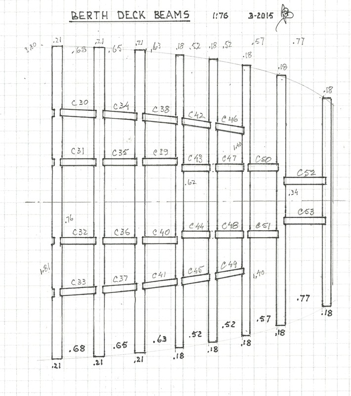
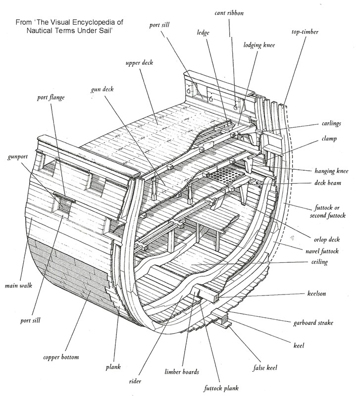
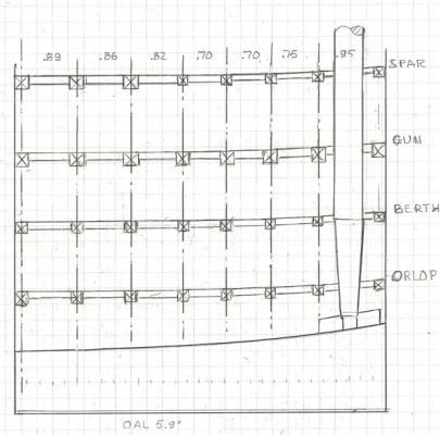
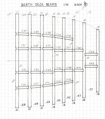
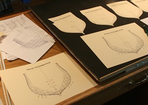
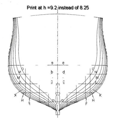
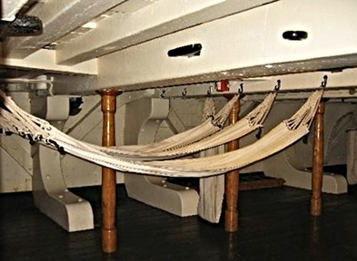
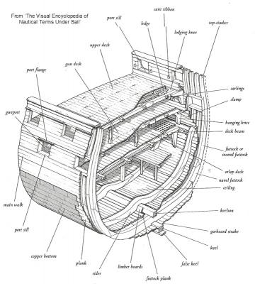
Deck Beams. The first step I took was to align the deck beams. I used the parts on the spar deck to fix the locations. The hatch covers, for example, have a beam on both sides. AOTS shows the cross beams (carlings) and joists which resulted in drawings for each deck. The one for the berth deck is shown below. The beam thicknesses were scaled from the books drawings, but again there were inconsistencies from page to page, so I am not positive about the results. Frames. For the frame shapes I used the cross sections H and O in the book (page 75) and generated others in between from the profiles shown on page 58. This resulted in seven shapes for the eleven frame sets. I will ‘estimate’ the shape of the others which are similar to those for F and H. I copied these to scale on heavy paper and cut out the outside of the profile. These will be glued to the wooden laminates and sawn to size. I intend to use the technique used by Harold Hahn to cut strips of wood and gluing them such that the grain is in the direction of the thin parts but also so the two pieces have the seams in somewhat different directions. I have done this with other frames as shown in the following thread: http://modelshipworld.com/index.php/topic/2191-hms-pelican-by-modeler12-per-harold-hahn%E2%80%99s-plans/ Knees. Special wooden blocks or knees are used where the deck beams meet the frames. Some of them are at an angle, others vertical. They are there to distribute the stresses imposed by the deck above. On page 60 of the book Marquardt shows long rows of the slanted knees but he fails to include the vertical (or hanging) knees. A picture of the gun deck is a bit clearer. Another picture of the berth deck shows very heavy curved knees to support the big guns on the deck above. I made drawings for each of those pieces, so I can cut them out when the time comes. Now it is time to put a list of materials together and order some wood. Meanwhile I appreciate comments and suggestions about my plans thus far. I could really use pictures of the orlop deck and some of the details there.

- 572 replies
-
- 10
-
-
- constitution
- frigate
- (and 1 more)
-
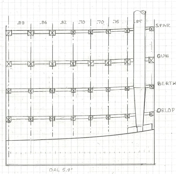
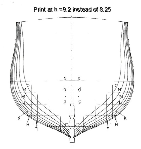
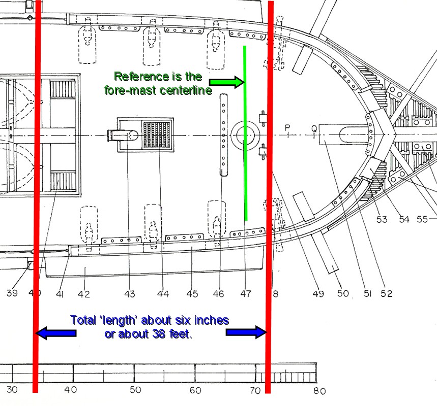
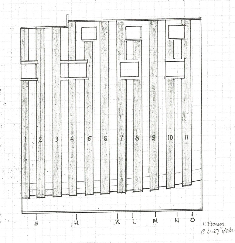
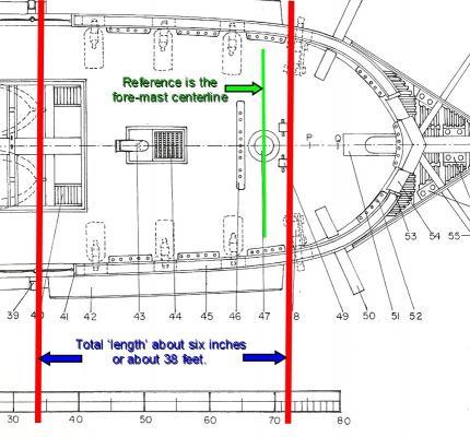
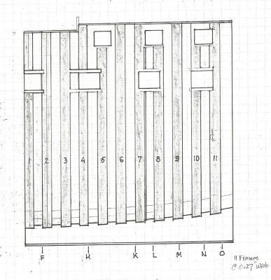
My full model is just about finished and I am looking into an additional compliment: a cross section of the USS Constitution. I want to build this from scratch and use as much of my abilities and tools as I can muster and try to do a decent job. However, to do research into details are usually not in my bag. But it turns out that I have to . . . The midsection has been covered by others (likewise with the aft section by one adventurer (help who?)), but I would like to show how the crew lived, slept, ate and filled gun powder bags. So, I decided on the area around the ‘stove’. As it turned out this area also shows some guns on the spar deck, part of fore-mast rigging, then more guns on the gun deck, hammocks on the deck below, the ‘sail room’ and ‘gun powder room’ on the orlop deck. But the main feature I like to stress is the hull construction in the forward parts. Hence, the frames, beams, knees and other timbers become part of the story. I am using the book by Marquadt ‘Anatomy of the Ship’ (AOTS) for the main reference. He shows a lot of great pictures of all phases and equipment used on the USS Constitution and I have learned a lot from his information. In particular, I chose the section between the stairs going down from the deck and forward to just ahead of the fore-mast. Using the same scale as my full model (1:76), that is about six inches, or 38 feet real. Page 51 shows a nice top-view of this. In addition, I am still using the drawings that came with my earlier kit of the full model; and here is where I ran into some problems (let’s just call them discrepancies):::::: 1. I mentioned earlier on a different post that the deck beams seemed a bit out of line. In fact the book shows supports at different decks that are not at all above beams below. They simply sit on top of deck planking. I ‘corrected’ that with my interpretation. 2. The frames making up the ship’s hull do not align with the gun-port holes like they should be. Yes, page 61 of the book has clear pictures of the frames, but those are incorrect (in my opinion). The locations of the gun-port holes do not correspond to the full model drawings I have been using. What is worse is that they do not correspond to the locations shown on other pages in the same book. Starting with these two dilemmas, I decided to take some liberties with the design and align the deck beams in a vertical plane and make the body frames along the lines of what Harold Hahn (bless his sole) did with his models. He took two ‘frame’ parts and laminated them to give a more rigid part to work with. Then he decided to eliminate every other one to make the interior more visible. I had to make some assumptions about the frame thicknesses and settled on what I show on the drawings below. This is still not ‘correct’ because the gun port openings should be between frames. But no matter how I juggle the frame thicknesses, I cannot come up with a way to do this unless I use frames of different thicknesses. So, here is where I am now. Mind you, I have not cut any material yet at this stage. I am just learning what to do.
- 572 replies
-
- 12
-
-
- constitution
- frigate
- (and 1 more)
-
Rich, you were brave to add sails and now you can say 'I've done it' and be proud of it. Looks great and I just know that your admiral will agree.
- 1,756 replies
-
- 2
-
-
- constitution
- constructo
- (and 1 more)
-
This is really nice work, Tom. It is fun to do a bit of work like this on your own. Sometimes it is trial and error, but in the long run it is very satisfying to see it all come together. Keep it up. You are being watched.
- 1,350 replies
-
- 2
-
-
- constitution
- model shipways
- (and 1 more)
-
Thank you Bill and George. The trip was just to see our grand-kids in southern California. All three had special events going like graduation from Cub Scouts, cheer leading competitions and a musical play (leading role in Shrek). The real trip will be next week when we are going to Hawaii for ten days. We'll be on a small yacht and visit Molokai, Lanai, Maui and Kona. There will be lots of snorkeling, kayaking, paddle boarding and merry making in the sun (we hope). I might mention that I am thinking of scratch building a cross section at the same scale as Connie. It would be forward and include the stove on the gun-deck, and go forward just to include the fore-mast. I think it would be fun to show how the crew lived, ate and slept, while further down it would also include part of the gunpowder and sail rooms. It would have only part of the mast showing and should fit on the first shelf of the display table. The two models then are 'complete'.
- 732 replies
-
- 2
-
-
- constitution
- model shipways
- (and 1 more)
-
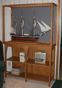
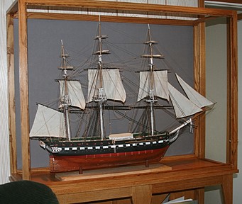
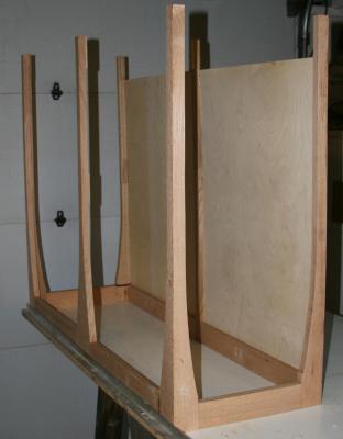
Here are a couple pictures of work in progress. The display case will have a door (with more glass) to the left and the top will also have a pane of glass. The grey background is a piece of fabric glued to a 1/4 inch piece of plywood. I still need to mount the boats, rig the braces, make a new base and generally clean things up before I can call it done.
- 732 replies
-
- 18
-
-
- constitution
- model shipways
- (and 1 more)
-
Here is a link to another discussion about blackening metal. http://modelshipworld.com/index.php/topic/1240-another-type-of-blackening-agent-and-some-experiments/?hl=blacken#entry23652
-
You are correct, Keith. Depending on the concentration, you don't want to use muriatic acid just to clean small parts. Of course, you can dilute it by adding some to water (and not the other way around).
-
On another forum someone asked if Dremel tools are made in Mexico. Here was one of the responses: ". . . this is Beth from Dremel. I have read yours and all previous emails in regards to the manufacturing of our Dremel tools. These ARE assembled in Mexico, however, for those that didn't know it ... our Dremel Company's parent is "Bosch Power Tools". This is a German based company with a very high reputation. Because we are a global company, we seek out the best prices for the parts for the assembly of our tools, world-wide, to keep the prices fair for our consumers." So who knows? Maybe some of the parts could come from China.
-
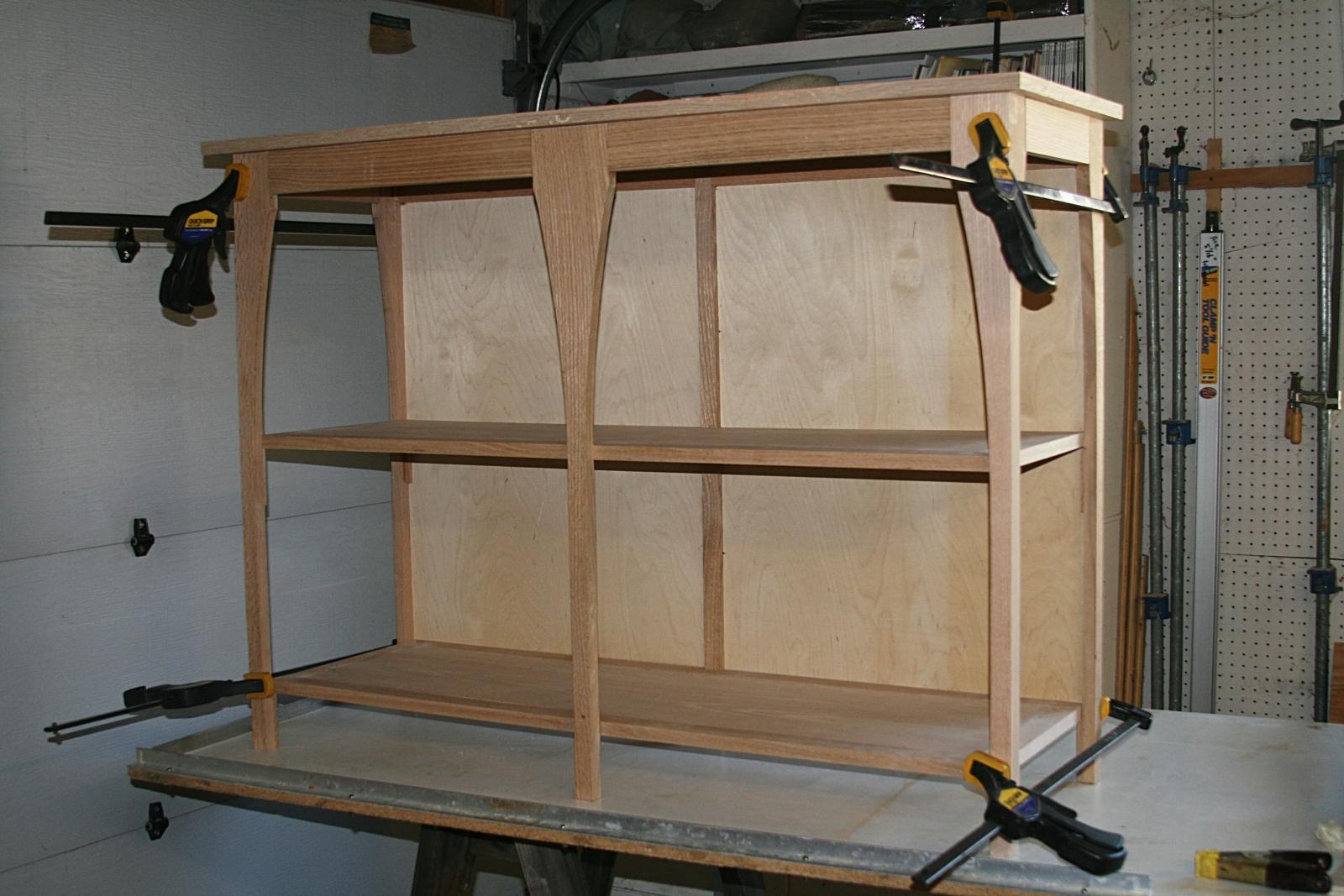
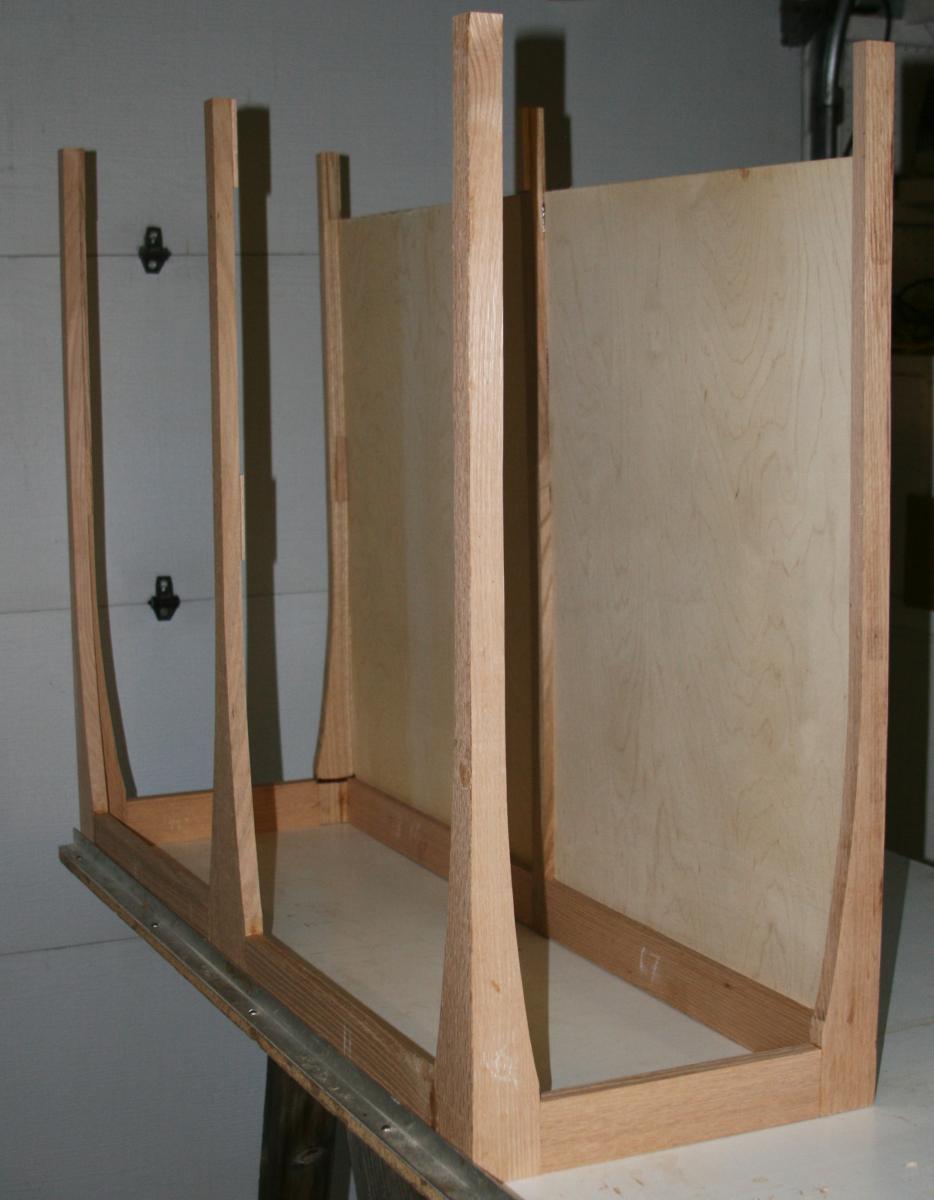
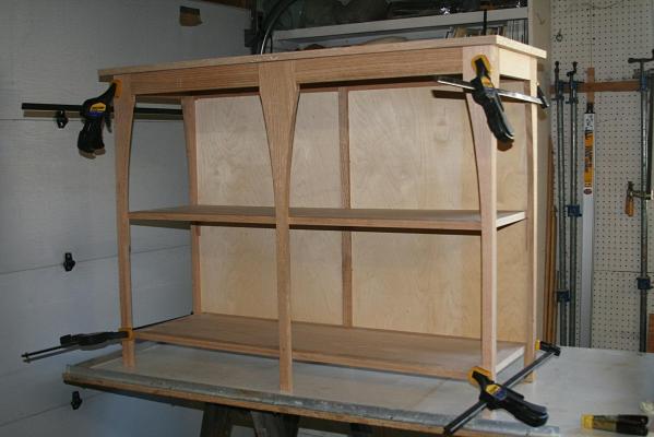
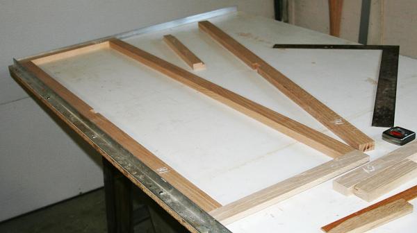
Update Things are moving slowly. Here is the table that will hold the display case. It is a dry fit to make sure the two shelves will meet the legs at the right spot. When assembled and glued together, the shelves will be part of the structure and glued to the legs at the corners. The top of the table is about 51 x 17 inches; slender but strong when finished. Because of the overall height with display case, the unit will be fastened to the wall where it is going. No tipping allowed. Now the admiral wants to see more of the world, so I will be gone for a while and the display case is on hold for a few weeks.
- 732 replies
-
- 5
-
-
- constitution
- model shipways
- (and 1 more)
-
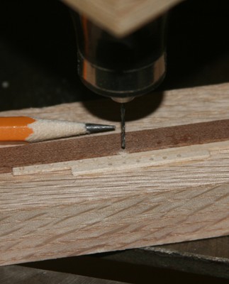
To install the rivets, you need to drill holes first. I used a dremmel like tool mounted to the quill of my drill press to drill holes on 1/8 inch centers and glued the back side of the plank with some PVA. Tedious? Yes, but . . .
-
Consider how you use a glue. For those very tiny applications you don't want to dispense directly from a bottle When it comes to epoxy, in particular, I mix small batches with a toothpick on a piece of very smooth scrap wood. I do the same with Titebond or 'carpenters glue' and even CA if necessary. I am a cheap skate and use both sides of the 'scrap wood'. Round toothpicks are excellent applicators. But like Ulises mentioned above, if I am building furniture (like the display case in the works for my Connie) I use quite a bit, but still not a whole bottle. I hate scraping glue of my fingers and the work I am doing. The less the better.
-
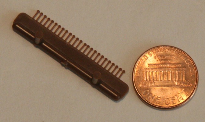
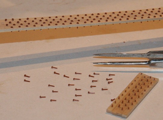
I am sorry to do it this way, but there is an excellent video by ??? about making metal screw or bolt heads and I lost it. However, for those who rather buy than make, here is a source for those little guys. The 'rivets' come in a cluster of molded plastic and was designed for the model train hobbyists. The smallest rivet has a head of 0.020 inches diameter with a shaft of 0.015 inches. For a model at 1:76 that equates to a shaft of just over an inch in diameter. https://www.tichytraingroup.com/Shop/tabid/91/c/ho_nbw--rivets/p/8017/SearchValue/rivets/Default.aspx I, and others here, have used the next size up for the 'rivets' in the bulwark of the USS Constitution. Here is what those look like. BTW I am sure most of you know that on the US penny Lincoln can actually be seen sitting in his memorial.

-
Scroll saw operation
Modeler12 replied to bigcreekdad's topic in Modeling tools and Workshop Equipment
Sorry, my mistake. I must have read it wrong. -
Scroll saw operation
Modeler12 replied to bigcreekdad's topic in Modeling tools and Workshop Equipment
What I did was to paint the block with some black spray paint. The first attempt worked fine (it was held in place with some double backed tape), but the color of the oak was distracting, so I 'blackened' it. The whole piece is oak. PS. The whole idea was mine, No copy rights involved as far as I am concerned. I even have my little drawing of the block if anyone is interested to see that. -
Scroll saw operation
Modeler12 replied to bigcreekdad's topic in Modeling tools and Workshop Equipment
Jaager, in order to use 'cool blocks' you still have to install the holder and make fine adjustments to make sure the cutting teeth don' touch the teeth. In my case it does not matter. If the teeth cut into the wooden block too much I can replace the block, but it does not damage the blade. In fact, for very small blades it almost becomes a fact As far as 'cool' is concerned, for me it has not been a problem either. I don't use the saw that much, but if I were to go on and on, smoke will tell me when to stop (and put another blade and back stop in place). To install this guide takes a bit of work. I ended up drilling and tapping two #4-40 threads into the foot and make the wooden block with a slot so I can adjust the for-aft position for the blade to clear. Once I was satisfied, I made several for easy replacements. DiKri, the way I read this new forum you mentioned, it wants you to join and then pay for what ever info you want. Perhaps I am wrong about reading the first page. Do you suppose that my idea could be worth something with those members -
Great, you got what you asked for, and it will be useful, believe me. I was about to mention another source, Hobby Lobby, if there is one in your area. It has one called a '23 x 35 inch Rotary Cutting Mat'. $30. Seamsters use them all the time, so the price should be better at one of those kind of shops. I bought one eons ago and don't remember what I paid, but they do a good job. Like others mentioned, don't expect them to fill in holes when you drill through it. I believe the material is polypropelene which is used in lots of commercial applications. As a plastic it has a tendency to 'fuse' together when minor cuts come through. But don't expect major gaps to be filled. If you were to cut all the way through the mat, I doubt it will come back together again
-
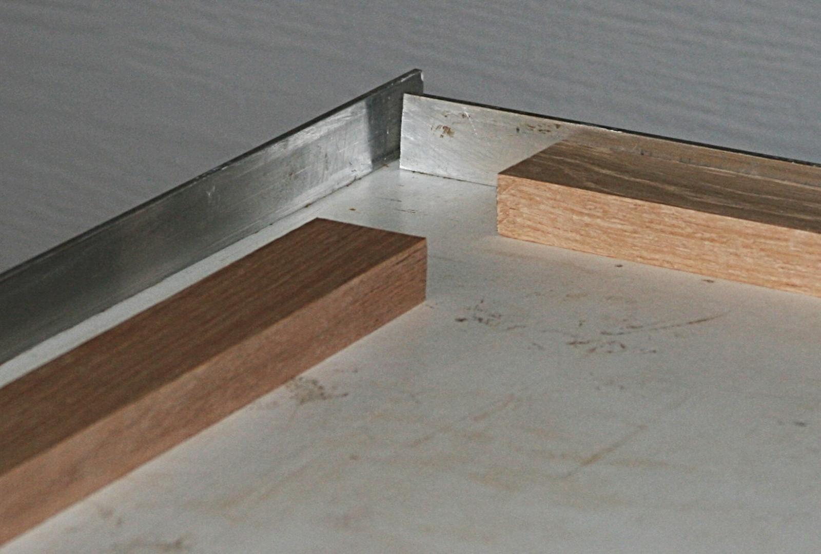
I don't know if this is of any interest, but as a wood worker I made this 'assembly table' several years ago and have used it numerous times. It is 3/4 inch thick particle board with a smooth, laminated cover. There are two aluminum angle pieces at right angles (with a small gap in the corner to let out dust). From time to time I give it a coat of wax so glue will not stick to it. I can store it along my garage wall and use a couple saw horses when I need it. I use it for a lot of work, both flat pieces and for final assembly. This is the table/bookshelf that will support the display case.

- 732 replies
-
- 12
-
-
- constitution
- model shipways
- (and 1 more)
-
Scroll saw operation
Modeler12 replied to bigcreekdad's topic in Modeling tools and Workshop Equipment
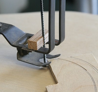
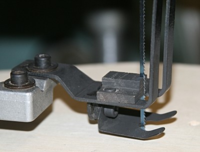
I made a 'guide' for the blade as shown below. The table also has a thin sheet of plywood for an almost zero clearance blade path. The first picture was my first try, the second is a wooden block bolted to the foot.