Modeler12
-
Posts
1,716 -
Joined
-
Last visited
Content Type
Profiles
Forums
Gallery
Events
Everything posted by Modeler12
-
 At this point, Mark, I am thinking of having the wires come through the keel and then up along the port side where the hull is planked in and outboard. Since the section will be visible primarily from the aft side, the wires can be attached to the forward part of a beam (if necessary) where it can then go up to what ever deck it is supposed to go to. The light room is easy since it will be low and at the center. A light on the berth deck can be behind one of the large knees on the port side and others 'to be determined' (the stove comes to mind). Right now I am putting the finishing touches on the full size Connie and taking care of a few items on the 'honey do list'. So the section will take a back seat for a while.
- 572 replies
-
- 4
-

-
- constitution
- frigate
- (and 1 more)
-
American sailing warships with no plans or records
Modeler12 replied to CharlieZardoz's topic in Nautical/Naval History
Based on the fact that some ships were taken by the British and then put into service by them, would a source in the UK be worth searching? They certainly would have 'discovered' problems that needed correction or modifications to bring the ship up to their 'standards' and recorded that. Most of the time they would rename the ship. Was the Trumbull still a Trumbull? If the original plans are no longer around, it would be interesting to see what the Brits did to it. -Providence 1776 28 gun -Trumbull 1776 28 gun both were captured by RN so wonder if plans were taken? -Delaware and Boston 24 gun ships taken by RN (there is a plan is Chapelle's book figure 4 dates 1748. I am wondering if this is the correct plan for this Boston) -Lexington 1775 brig (I have seen models and plans of this ship but are they based on actual plans taken by the RN after capture?)- 401 replies
-
- 1
-
-
- John Adams
- Alliance
- (and 3 more)
-
Thanks Anthony, I will have to digest this and give it a try. The LEDs I bought also are available as 'flashing' which I assume is not the same as 'flickering'. They probably have a small capacitor that charges and discharges are set intervals. I like your idea of flickering for the fire in the stove, for example. The size I started with is the 1.8 mm, but I may get some of the smaller chips. I have tried the nano and pico sizes a year or so ago, but found the light output be too small. For a real candle, though, it would be nice.

- 572 replies
-
- 4
-
-
- constitution
- frigate
- (and 1 more)
-
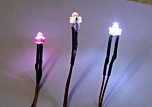
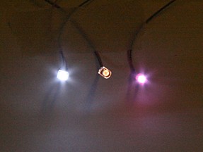
Hi Carl, Here are a couple more ideas that work with those LEDs. I painted the red with some more acrylic paint, but it still had that crown effect. So I sanded off the dome on this particular item and added another touch of paint on top. It worked and now it looks more uniform. If, however, you want to 'spot light' something you can do that with the 'dome'. I am really intrigued about what you can do with these little guys.
- 572 replies
-
- 4
-
-
- constitution
- frigate
- (and 1 more)
-
Flags of the french ancien regime navy
Modeler12 replied to Nwanda's topic in Nautical/Naval History
I would suggest you contact Mr. Joseph Mcmillan at Seaflags j_mcmillan@verizon.net He is the principal contact for anything having to do with Seaflags, a great source of information about flags from around the world. http://www.seaflags.us/seaflags.html Although this web site deals primarily with US flags, Joseph may have an answer for you. -
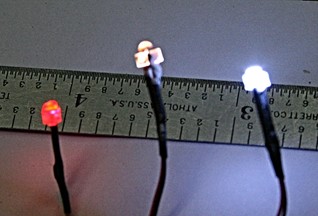
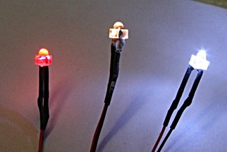
Mark, I am using LEDs that require only 3 volts, which is almost the minimum voltage needed to make them work. The little transformer that came with them puts out the 3 volts. Hence, adding a resistor or pot to reduce the voltage will not work for me. Painting the LED does reduce the brightness, although the white paint I used makes the color somewhat tan looking (which I think is fine for a lantern or candle light). You can also add color such as the red one where I used a red marking pen. Red paint would have reduced the brightness. I am toying with the idea of using something like this inside the oven (yet to come). Below is the comparison looking from the side and head-on. George, In my case the cross section will be 'finished' along the port side and I can hide the wires inside the walls and behind the beams and below the deck planking, if necessary.
- 572 replies
-
- 4
-
-
- constitution
- frigate
- (and 1 more)
-
Clevises - I think?
Modeler12 replied to Landlocked123's topic in Metal Work, Soldering and Metal Fittings
Your soldering looks great and the details of your wire bending is very commendable. What scale are you working with? For me this would be a bit too big. At 1:76 the thickness of the shackle wire would equate to almost 1.4 inches and the pin double that. Shackles I have used are about one fifth or less than that. Of course, I am talking small sail boats. -
Landlubber Mike's technique for furled sails
Modeler12 replied to Landlubber Mike's topic in Masting, rigging and sails
I also like to add some cents here. Thanks to you, Mike, I decided to add the furled sails to the top spars (after having full sails and rigging on the topsails). That added a lot more interest. Here is one picture of the process you described. It worked very well. I like the idea of having the sheet still be visible and I had that going to the spar below. I did not add the other lines and blocks that are part of the whole rigging picture.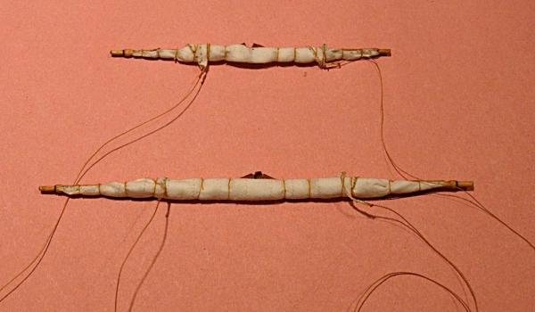

-
No, I did not get the idea from another cross section, George. But I have seen the little micro LEDs used for lanterns and even a candle stick. I will leave my options open but do need to include the wiring through the keel and later through the display base. One reason I have not completely finished the frames and keel is just so I can think about other additions and the possible interference of some of those added parts.
- 572 replies
-
- 2
-
-
- constitution
- frigate
- (and 1 more)
-
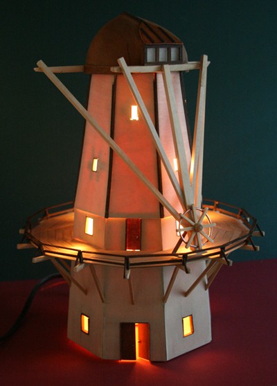
George, the LEDs are not my idea to start with. About a year or so ago there was some discussion about using them inside models and I used them on a couple windmills. (see below). To install them you have to plan ahead and provide the leads and power supply. In my case I will be using a small transformer that plugs into a wall outlet, has a tiny switch and thin wires to the LED. It is a matter of locating them and feeding the leads well in advance so they don't interfere with the rest. Beside the 'light room', I want to add at least one more on the berth and gun deck. But I want to hide them from direct viewing.

- 572 replies
-
- 4
-
-
- constitution
- frigate
- (and 1 more)
-
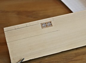
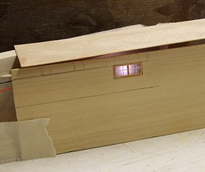
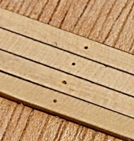
The walls of the powder room will be 1/32 inch boxwood. I made the windows using a piece of clear plastic, sanded to remove the release agent and give the windows a translucent look. The trim is made of some veneer which I will also use for the vertical firring strips. The muntins are made of pin striping tape, 0.010 inch wide, glued in place with some CA. I may do this again and try to align these tiny pieces a bit better. Just for scale, 10 mil equates to 3/4 inch full size and I tried to keep the wood strips to about three inch width. Next to it is the same wall with an LED in the 'light room' behind the windows.All of this is loose and will be cut to fit and installed later. BTW The LEDs I ordered are rather large and bright. I should have bought the smaller versions. However, the brightness can be reduced by painting the LED with some white paint. They do not generate heat, so there is no problem there.
- 572 replies
-
- 6
-
-
- constitution
- frigate
- (and 1 more)
-
Indeed JS, I have seen pictures of Gene's model. I believe it is on display at the museum in Boston. I have a long way to go and taking my time for this project. Right now I am putting some plans and details together for the forward powder room that goes in the bottom. But I am also working on the various decks, as you may have noticed.
- 572 replies
-
- 2
-
-
- constitution
- frigate
- (and 1 more)
-
comparison of masking tapes
Modeler12 replied to vaddoc's topic in Painting, finishing and weathering products and techniques
One problem with Frog tape (and perhaps with others like it) is that when it is cut to a certain pattern the edge is removed and the benefit of its properties is also gone. When you read how Frog tape works you find out that the edge of the tape is treated with a special chemical. Once that edge is removed, you are back to regular masking tape. -
One way to identify wood is to compare it to other known sources. Here is a very comprehensive series of wood samples http://www.wood-database.com/ Perhaps you can find one that matches or is close.
-
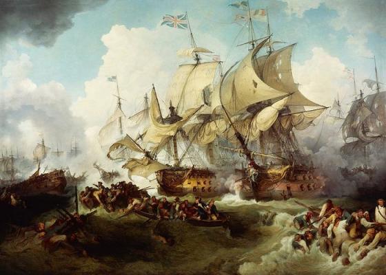
June 1, 1794. First and largest naval battle between France and England. Here are some of the details according to Wikipedia: The Glorious First of June, (known in France as Bataille du 13 prairial an 2 and sometimes called Third Battle of Ushant) of 1794 was the first and largest naval action between the French and British fleets during the French Revolutionary Wars. The action was fought over 400 miles (640 km) west of Ushant, the most Western point on Britanny in France, deep in the Atlantic Ocean. The British fleet under Lord Howe was attempting to defeat a French fleet under Villaret de Joyeuse which was in turn attempting to lure Howe away from a grain convoy destined for France from the United States.[1] The future of the French Revolution depended on this 117 strong convoy which would save France from famine if it arrived safely. Ultimately, both admirals were successful in their ambitions; Howe defeated Villaret in open battle and took seven of his ships. Villaret managed to occupy Howe for long enough and inflict sufficient damage that the convoy escaped unscathed.[2]
-
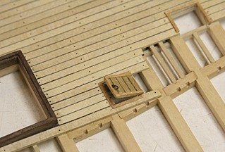
Just for fun here is an addition to the orlop deck. It is the cover to the entrance to the gunpowder room below. This is still loose and I can install it later raised or lowered, depending . . .? Notice also the opening top right which will be the stairway to the light room, also down below. There are going to be walls/partitions to show the 'sail room', the boatswain's store room and, of course, the 'carpenter's walk'. But they will have to wait until I know exactly how high the gun deck up above will be. Also in the picture are the slots for the ledges fitted later on in the carlings.
- 572 replies
-
- 7
-
-
- constitution
- frigate
- (and 1 more)
-
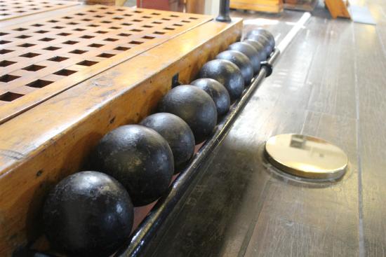
Good question. There have been so many things that were changed that it is hard to tell the original from the current. It would seem, though, that to add these scuttles during a refit would not make much sense unless they had a good purpose. When I found that picture of the boy holding the pouch it dawned on me that there was a purpose for those 'ammo passing scuttles'. Of course they may also have been used to pass cannon balls from below. And they were not only on the spar deck. Here is a picture of one on the gun deck (with strangely different size balls).
- 572 replies
-
- 6
-
-
- constitution
- frigate
- (and 1 more)
-
Absolutely, go for more thickness because it will disappear with all the sanding you will be doing to get a nice and smooth hull, deck or what-ever it may be. It is easier to remove than to add.
-
Thanks Mark and George, For this cross section I am taking a chance that putting the six inch long decks together on the work bench and then inserting them into the framed hull will work. Obviously it is not something that would work on a full model. This way I can do a lot of work (such as all those thin pieces of joists) without having the frames get in my way. The exception will be when I have to install knees along the outside edges of the orlop deck for example. However, again I will only do that along the starboard side since the other side will be planked over. Now I need a break and do a few other things around the house. The admiral has spoken.
- 572 replies
-
- 4
-
-
- constitution
- frigate
- (and 1 more)
-
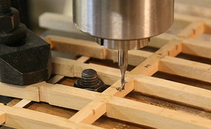
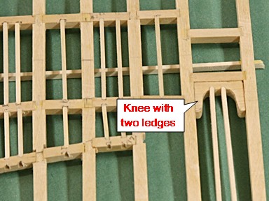
Moving along with the berth deck: This is a bit more difficult than the orlop deck. The beams are curved and with all the carlings and stringers it becomes hard to keep track of how to cut the slots (mortises) for each one. My mill comes in handy. I use a 1/16th inch cutter to make these slots. Most of the time I do this on the beam or carling, but there have been a couple times when I needed to add some more and then I have to mount the whole thing on the mill table. Making the 'knees' is another interesting proposition. Here I used a piece of boxwood of the same thickness as the beams, drilled a couple holes for the inside curve, filed, and slotted this for two stringers (ledges). It is a lot of extra work and there will be lot more to come.
- 572 replies
-
- 8
-
-
- constitution
- frigate
- (and 1 more)
-
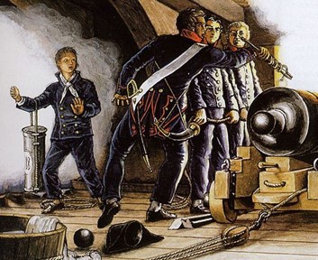
Here are some more details about how the cartridges made in the gunpowder room were transferred to the gun deck. I found this picture on Wikipedia of a drawing of a French ship firing a cannon. There are several details of interest, but the one I zeroed in on was the boy holding the leather pouch which probably held the cartridges ready for reloading the next round. On top of the USS Constitution there are several holes, covered with a brass lid, that were probably used by young boys to shove these pouches, full of gunpowder cartridges, from the deck below. The pouches were filled in the powder room and the leather protected the cartridges from moisture. The idea of young boys running around with cartridges stuffed in their shirts is outlandish to me, unless it was a last effort. My guess is that the leather pouch was about eight to ten inches in diameter and 18 to 22 inches long. The hole in the spar deck of my model is about 14 inches OD (with lid in place). So my guess is that the hole was about 12 inches in diameter, enough for the pouch. So, in my cross section I will have to include some pouches
- 572 replies
-
- 5
-
-
- constitution
- frigate
- (and 1 more)
-
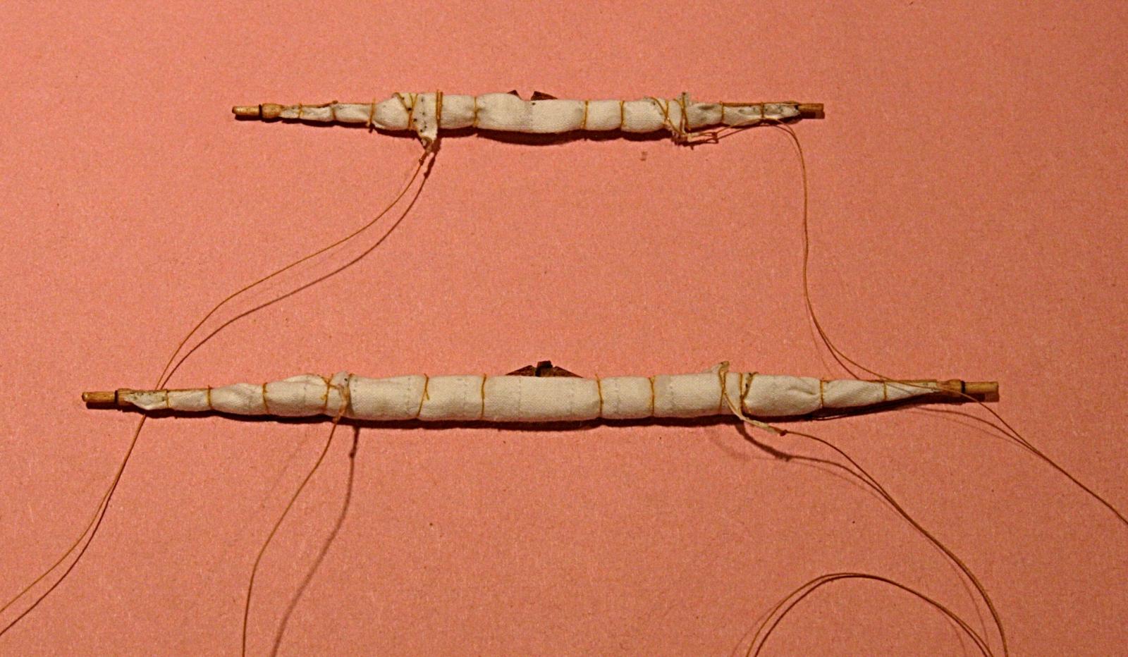
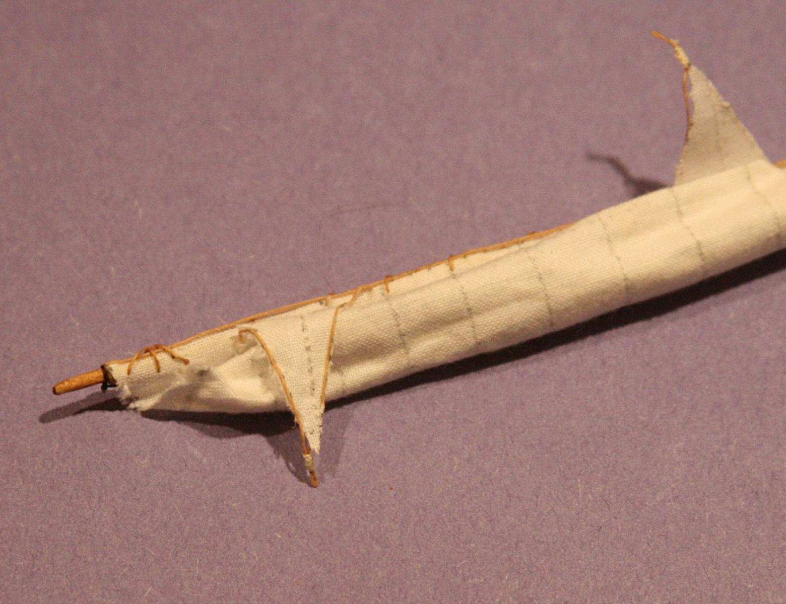
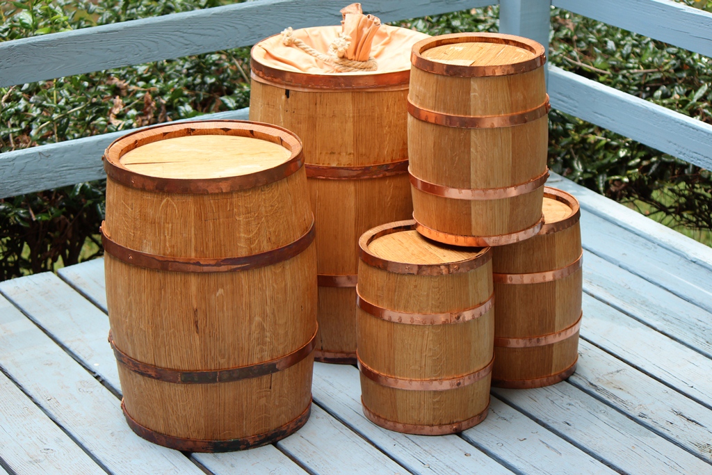
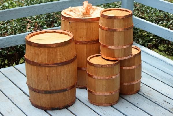
I posed the question about gunpowder barrels in another place. I think it was removed which is fine because it did not lead to anything serious. However, a bit of further searching led to the following: 1. Wooden barrels were used to hold just under 100 pounds of gunpowder. I will calculate the size based on this info and use it to make my barrels with copper foil for the hoops. 2. The hoops of the barrels were made of copper. Iron hoops were not allowed because of the possibility of sparks. 3. For the same reason tools such as hammers were also made of copper. 4. To open a barrel, it was set on end and the top hoop was removed by hitting it with the copper hammer and punch. This loosened the top cover which could then be removed to expose the powder inside. 5. Other tools such as the scoop to transfer the powder to the 'filling station' or open box were also made of copper or wood. Here is the reference for some of this on pages 403 and 404 https://books.google.com/books?id=EryS0HCykUkC&pg=PA404&dq=why+use+copper+on+gunpowder+barrels&hl=en&sa=X&ei=uOJhVbX3Nca2sAXkyoHwAQ&ved=0CB4Q6AEwAA#v=onepage&q=why%20use%20copper%20on%20gunpowder%20barrels&f=false PS There is an interesting quote on the bottom of page 341 about Naval Happiness. A quick calculation of the size leads to a height of about 20 inches and diameter of 13 inches. Thus not too far from the one shown as a 'seat' in the picture above. This is based on a specific gravity for gun powder of 1.5. Small barrels with lots of poooof!
- 572 replies
-
- 6
-
-
- constitution
- frigate
- (and 1 more)
-
Mark, I think I will stick with my method of using brass and the blackening solution I have. Below is a close-up of the four planks I showed earlier. It has been only four days but there is absolutely no indication that the patina had any effect on the wood. The width of each plank is 1/8 inch (holly). The only problem of using metal tree-nails is that the surface has to be sanded. Scraping (like I have done before) will not work; even though I used a drop of CA glue on the back side when inserting the brass wire. In fact, as I look at this close-up I noticed that a bit more sanding with a finer paper would have been good. Something I need to keep in mind.
- 572 replies
-
- 5
-
-
- constitution
- frigate
- (and 1 more)
-
Thanks Mark, I will look into this. I have some copper wire and can get the liver of sulfur at a local jewelry store (I hope). I also found a good article about how to handle the stuff. Now I have to find a place to use it since the sulfur can smell pretty badly. http://www.hodgepodgerie.com/liver-of-sulfur-patina.html What I like about the brass is that it is stiff and easy to force into the pre-drilled hole with a pair of pliers. The blackening solution I use seems to attack the brass very quickly and not do harm to the wood as long as I wipe it off with a damp cloth right away. Of course, once I apply the patina I cannot sand the surface again without removing the oxide. Hence the wipe-on-poly. I will keep an eye open for the samples I prepared and see what happens with time.
- 572 replies
-
- 3
-
-
- constitution
- frigate
- (and 1 more)
-
One more thing about the pictures above. They also show my tries at 'tree nailing'. What I did is to use thin brass wire, drilled the same diameter hole in the plank and used some CA glue to set the wire in place. I think I covered this earlier. However, what I wanted is to have the wire be black (not shiny brass). So, after sanding the surface, I applied a drop of my blackening agent, quickly rinsed that with water, dried it and applied a coat of rub-on poly. The alignment of the tree nails is not good, but the idea is there. This is not as hard as it may sound and it works. If you want more details about sizes etc. let me know.
- 572 replies
-
- 3
-
-
- constitution
- frigate
- (and 1 more)