Modeler12
-
Posts
1,716 -
Joined
-
Last visited
Content Type
Profiles
Forums
Gallery
Events
Everything posted by Modeler12
-
Wow, lots of good ideas. I agree with most of them. I have a couple different soldering irons which I have used for large and small projects. The smaller the job, the smaller the iron. But in all cases the tip needs to get the juice. If it is loose: tighten it. If it is bare: coat it with solder. But in all cases: use flux. I have some liquid flux that survived from the stain-glass working days and it still does the job. I also have a cheapy iron that works very well, but I also use a rheostat to control the heat. It is home made (dimmer switch). I hope by now we all agree:::: Check the simple iron you have. It is not magic how they work. Don't spend more money on a new one.
-

Silver Soldering Tools
Modeler12 replied to bundybear1981's topic in Metal Work, Soldering and Metal Fittings
Thanks for pointing this out. I still have the old pictures and will make a correction. I also mentioned this in my log. I don't know how that happened, because the original post here was complete. Done. Go back a page to see the extra pictures. Perhaps this makes more sense. -
Rat lines revisited, a different approach
Modeler12 replied to Modeler12's topic in Masting, rigging and sails
Let me add one more comment. The pictures I show above are just for a mock-up. I don't mean imply that you would build the shrouds and ratlines on the bench and then add them to your ship. No way. The shrouds have to go onto the ship right when you are ready. Then the ratlines go on last. -
Rat lines revisited, a different approach
Modeler12 replied to Modeler12's topic in Masting, rigging and sails
I think that could be a problem. I suggest you fit the bulkheads in place but don't glue them yet. As suggested earlier, be sure they fit snugly but not too tight. Now take a flexible rod, plank or long ruler and hold that up against the side and top of those bulkheads. Perhaps by making some adjustments to one or two of those bulkheads upwards and/or sideways you can overcome the bow. The main thing is that the bulkheads provide a smooth surface for the planks later on. When all looks good mark the bulkheads you adjusted so you can come back to that position when you glue them in place. -
Rat lines revisited, a different approach
Modeler12 replied to Modeler12's topic in Masting, rigging and sails
I am sorry, but I don't understand something here. Installing the shrouds around the mast is usually done in pairs going down on the same side (port or starboard). If there is an odd number of shrouds, one leg goes to port and one to starboard. However, this has no bearing on installing the rat lines, no matter what technique you prefer to use. The shrouds go first and then the ratlines, not pre-assembled. If you look at my experimental setup, you can see the nails on top. Those would be the mast and shrouds loop around that. The bottom obviously does not have the deadeyes, because in this try they would be redundant. -
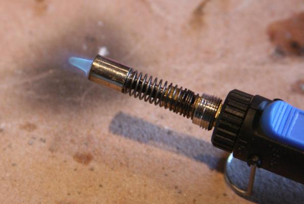
I notice that there are three pictures missing in the post above. Here they are again for what ever it is worth. The first has to do with the adjustable flame size. The second shows too much silver in the joint and the third is related to repairing a joint using another paste. The Solder-it is a grey paste. See the post again if interested.

- 732 replies
-
- 2
-

-
- constitution
- model shipways
- (and 1 more)
-
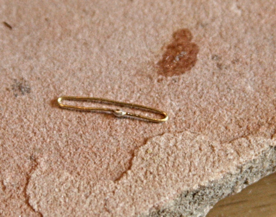
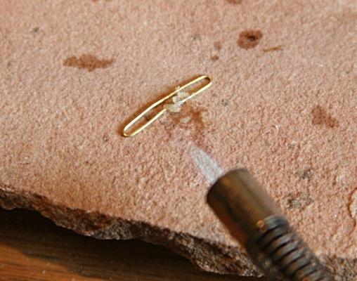
Harv, the video is a bit old and the idea of using pellets of the brazing metal came from a lady who makes jewelry. Since then I switched to using a paste that incorporates the silver. It is much easier to use. For some details and name of the compound go to an earlier couple posts: http://modelshipworld.com/index.php/topic/1888-silver-soldering-tools/page-2?hl=%2Bchain+%2Bplates#entry141293 It is post #28 and 29 in that series. You can buy the Solder-it from several places. Just google it. When I made the small hoops I tried to close the wire as best I could. When a tiny amount of the flux is put on top of the joint, I also use a toothpick to apply the paste. I also hold the torch at a slight angle left or right and let the flame hit the metal away from the 'eye'. The silver has a tendency to flow towards the heat source. Notice that it takes a second or so to make the joint on thin wire. The amount of heat is concentrated and I can actually use masking tape to hold the parts to the stone plate. Just for fun, I opened the box with the torch and flux this morning and even after more than a year the flux is still good. Just be sure to close the tube after use because it will harden when exposed to air.
- 732 replies
-
- 2
-
-
- constitution
- model shipways
- (and 1 more)
-
To expound on Suggestion 14 I was really surprised that I could not use my bent-tweezers when I wanted to grab a line or rope. Only the tip would hold. Of course, that should have been a clue. When holding this thing up towards a light you could see. Bending the prongs of a tool is simple. Use a vise or other tool to hold one 'leg' and bend the other a little at a time util it seems right. Even the hemostats I use can be bend to enlarge the holding gap. Suggestion? Try these ideas and let me know what you suggest.
- 732 replies
-
- 1
-
-
- constitution
- model shipways
- (and 1 more)
-
Suggestion 14 Check your tools from time to time to make sure they are clean and sharp. Obviously a dull Exacto blade is not what you want to use (I do from time to time). Replace the blade or resharpen it. In my opinion a touch with a fine diamond tool works faster and often better than replacing a blade. This will bring up a lot of suggestions, I hope, about sharpening all of our tools. I use my tweezers a lot when knotting and tying lines followed by some CA. The glue will build up between the blades. Clean them!!! Adjust the gap if needed. That goes for a lot of other tweezers and clamps!!!! You would be surprised how they look and why you were not able to grab something.
- 732 replies
-
- 1
-
-
- constitution
- model shipways
- (and 1 more)
-
Rat lines revisited, a different approach
Modeler12 replied to Modeler12's topic in Masting, rigging and sails
Indeed Rich, tying those clove hitches is not too difficult if you can get to them easily. That said, I must admit that my approach to the rigging of my Connie is a bit unusual and the room I had to work with on those futtock shrouds was too tight to put in clove hitches. Again, I present this optional approach for those who are working with small scales and small ships. I don't think I will use this on the last of the ratlines I still have to install on my model (the starboard fore). -
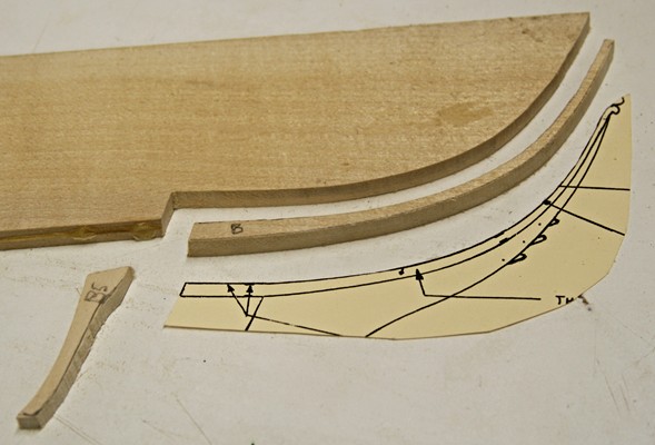
Suggestion 13 This one requires some explanations. It has to do with the bow and the complicated top and head rails. My point will be to use some thin plywood instead of the three pieces Mr. Hunt used and describes in nice detail. I thought I followed his instructions: Here is what happened the first time, and what it looked like afterwards. I had reversed the bonding of the two joints. After turning the two pieces the right way, I still had to add more wood in order to make the curve that goes underneath the cathead. As long as these parts are painted black, I decided to make the last two pieces out of plywood. It is a lot stronger in both directions (no oops). When you look at the first picture above and substitute plywood you can appreciate that subsequent operations are less likely to break those thin pieces. The last picture reminds me of some Alaskan Indian carving/painting. It was taken before the head rails became a question.

- 732 replies
-
- 5
-
-
- constitution
- model shipways
- (and 1 more)
-
Rat lines revisited, a different approach
Modeler12 replied to Modeler12's topic in Masting, rigging and sails
Let me add one more application for those of you who are doing the USS Constitution. The main stay and preventer stay are tied together with a 'snake', a thinner line that criss-crosses between the two. The technique described above would be a natural for that. I tried it the hard way with needle and thread but again settled on using adhesive. In fact, I used thin wire instead of thread, but with the method above, a thread would work. On second thought, a thread would be too flexible and the wire keeps the two stays in place. Notice the template underneath.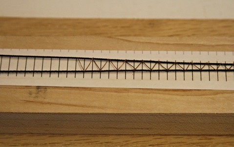
-
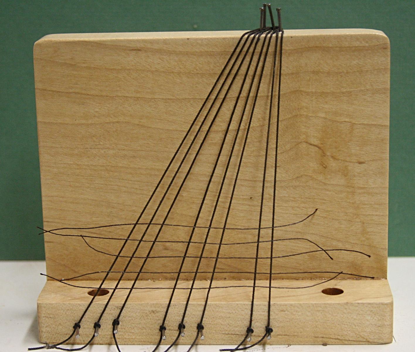
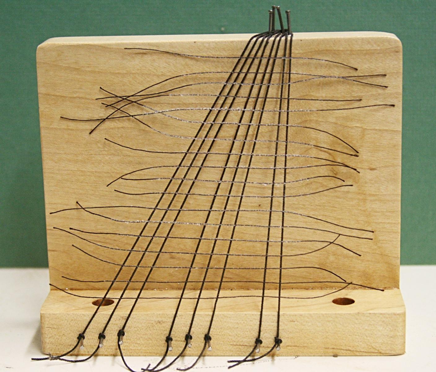
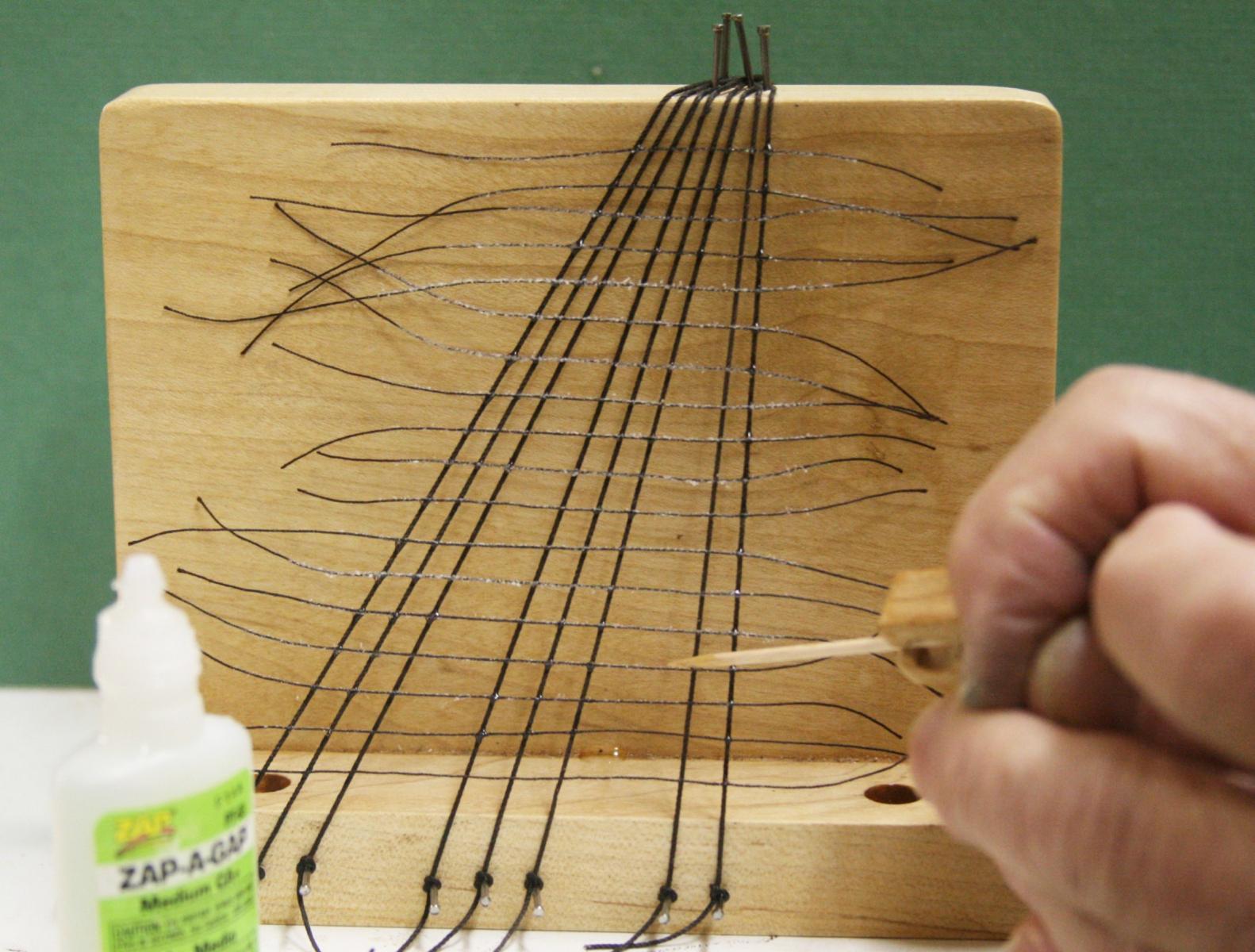
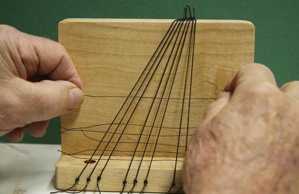
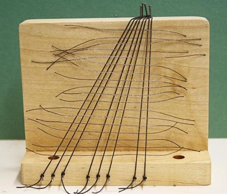
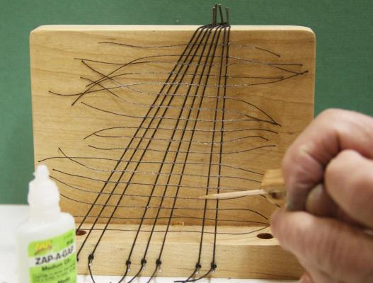
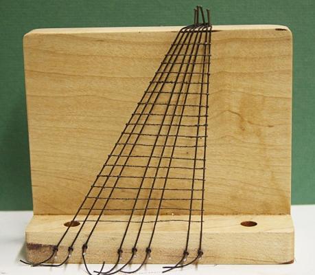
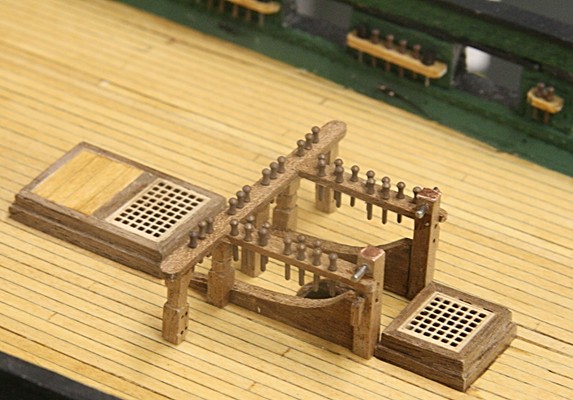
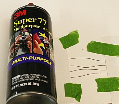
Ratlines have always been tricky to install on ship models. My hands are very clumsy and tying the rat lines to the shrouds was near impossible. So, I resorted to using a needle and thread approach. At least the outside shrouds were punched through and a tiny drop of AC glue held them in place. Then I ran into a very tight spot when I had to add rat lines to the futtock shrouds. They slope backwards and the other parts up there got in the way. I decided to glue the rat lines and the best way to hold them in place was using some contact adhesive. Then after that was dried I added a drop of AC glue to permanently hold the ends in place. It worked although the result was not pretty. I decided to try this a bit more on a larger scale. Below you can see the simple fixture I used to hold eight shrouds. Mind you, this was strictly an experiment. I was not particular about the size of line and the overall lengths but I did want to have some spaces in between, similar to a real set up. Then I took sections of rat line, masked the ends with a couple index cards and sprayed the adhesive on the exposed lines. The tacky adhesive was enough to hold the lines to the shrouds and the placement was relatively easy. After the glue had dried, I went back and added a tiny drop of CA glue to every joint. I let it cure for several hours and then trimmed the excess lines. To make it look more uniform I also gave it a quick coat of spray paint, but that was not really necessary. I am sure some of you may not go along with this idea, but for small scale projects It could be a nice way to go. It sure beats pricking my fingers every half hour with a needle.

-
Thanks for those comments, guys. Here is one more: Suggestion 12 When you do the deck planking (or the hull for that matter) think about the spacing of the beams and make the joints as well as any tree nails line up on top of those beams (whether or not they are there). For example, the hatch ways would have a beam on both sides and sometimes (depending on size) one at the center line. I did not do that as shown in the picture above. It requires just a little more planning but a purist would notice if they don't line up. Now you can see that I also have a lot to learn. Next time!!!!
- 732 replies
-
- 2
-
-
- constitution
- model shipways
- (and 1 more)
-
Suggestion 11. Try to learn and use soldering and/or brazing techniques to make the various metal parts come together. That sounds easy and it really is. It requires a few inexpensive tools, lots of practice and mistakes, but, in the long run, you will find it to be rewording and fun to try. I only burnt two fingers four times!!! I even put a video together about some of this: Let me think some more!
- 732 replies
-
- 6
-
-
- constitution
- model shipways
- (and 1 more)
-
About suggestion 7. Here is what I had. Simple, neat, but too weak. With some upward forces on the lines that are tied to the belaying pins, the whole thing lifted up off the deck. The glue simply was not strong enough. Fix? Extend some or all of the posts into the deck below or attach an extension to the bottom of the posts that go into the deck. That goes for several other places. Obviously this picture was taken before I realized that I would have a problem during the rigging. If I had only thought about this before hand!!!
- 732 replies
-
- 3
-
-
- constitution
- model shipways
- (and 1 more)
-
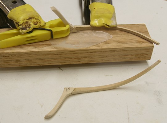
Suggestion 6. Keep your hand off those outside port lids and other details. They may give you an idea what it will look like, but too many will be a hindrance later on. If you have to, do a couple and see if they survive the rubbing and onslaught of your rigging operations. Add outside details for last when it can be done without several 'repairs' (and I have done enough of those!). Suggestion 7. When mounting the fife-rails to the deck, don't stop by simply glueing them to the deck with CA or even epoxy. There will be lots of upward tension on them when you do the rigging. The best way is to make the legs of those parts longer and have them go below deck (which is the way they are on real ships). Another way is to attach some wire to the bottom of each and have that go below with epoxy). I had two of them pull straight off the deck when rigging. To repair them I drilled a small hole in the bottom of the post and a matching hole in the deck. A brass wire (similar diameter) was then glued into both of them with more epoxy and some dead weight to hold it in place. Suggestion 8. Make the tiller the way I show it. Mr. Hunt was really up-a-creek on this one. He suggested to use styrene sheet and cut the supports to that complicated shape. A better way is to follow the plan and bend some wood for part of the frame (I think I showed that somewhere on this log). Suggestion 9. This one belong towards the top. Almost every eye-bolt you install should be there with epoxy and not CA glue to hold them in place. I ran some experiments with parts made with steel, brass, blackened eye-bolts, etc. and every time I was able to bend the metal before the epoxy gave out. Not so with the CA; some pulled out without much resistance. This is a real nuisance when you find out that the line you were attaching to that eye-bolt pulled right out (line, hook and sinker). Of course, you all know how to mix and apply a small dab of epoxy?!?!!! And, yes, they take longer to grab and cure, but for eye-bolts that generally is not a problem. For really strong bonds, let it cure at least overnight.
- 732 replies
-
- 4
-
-
- constitution
- model shipways
- (and 1 more)
-
I am sorry for skipping around, but my input comes and goes. Suggestion 4. When the outside of the hull looks good, leave it alone for a while. Let's look at the deck. I wished I had planned the deck planking better and have those nice scarf joints along the border. There should be a 'wide plank' for the border and then some neat looking joint as you go along. Most of this will be hidden by the gun carriages, but there will be areas near the bow that show. Look at the plans and plan !!! Suggestion 5. The gun carriages are neat to build. They add lots of interest. To put the blocks that came with the kit would destroy that image! They are square, the wrong size and look plain ugly! Get better blocks for the gun tackles. Somewhere I showed the difference on this log. That also means using 'rope' of the correct size (or close to it). Which in turn means drilling the holes in those new blocks a bit bigger and also to add a drop of AC to the end of the rigging line to make it stiff so you can go through those tiny holes a bit easier.
- 732 replies
-
- 1
-
-
- constitution
- model shipways
- (and 1 more)
-
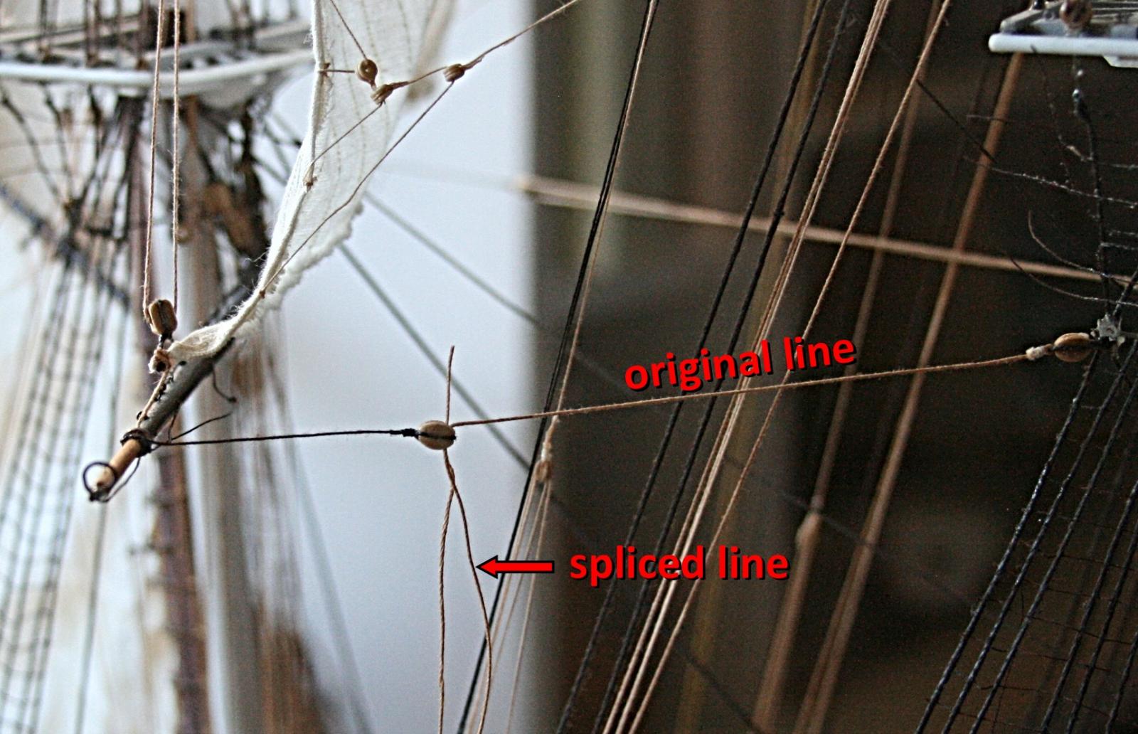
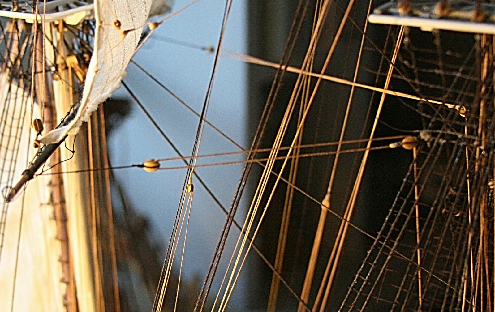
Do you ever run into a situation where you have to replace a line? Here I accidentally cut a line that would be a bit hard to replace. So, I decided to try to put in a splice, but one that would not show too much. I drilled the hole through the block a bit bigger, pulled the original line through and added the new line through the block in the opposite direction. I then made sure all the tensions were as I wanted them and put a drop of CA at the top of the hole glueing both lines to the block. Then it was a matter of trimming and smoothing things out, and redo the rigging of the new section. Notice I used a bit of CA on the end of the new line to stiffen it and make it easier to pull it through the block. Here is the result. The picture was taken at dusk, hence the artificial light coming from the left. Also the block in question is now turned upside down. If you are sharp you might also see that the block is turned the wrong direction. The hole or sheave should be to the left. So maybe I will replace this one.


- 732 replies
-
- 4
-
-
- constitution
- model shipways
- (and 1 more)
-
Bill, I agree if my hands were not as old and clumsy. I tried several approaches and tying was one (with bent tweezers), But the knots slipped or the line was too loose. I'll try to show the results with the contact cement approach later.
- 732 replies
-
- 2
-
-
- constitution
- model shipways
- (and 1 more)
-
Suggestion 1. On the first page of this build-log I showed how I started the hull. It included the way I pre-built the gun ports. It was a lot easier than putting one piece of each port in place. What I did not mention is that it is important to define the vertical size on the basis of what the width is for five hull planks. My kit had hull planks that were very ratty along the edges. I sanded them a bit to get sharp planks. However, this reduced the overall width of the plank and the combined height did not match the gun ports. I had to use small shims to correct this. Point is again to think ahead. Suggestion 2. If you decide to put rivets in the bulwarks, don't do them one at a time like Mr. Hunt did. Set up a 'assembly line' as shown on page 1. What is more important is to reverse the order of this construction (something I did not realize until much later). What I mean here is to do the planking of the outside hull first and then come back, cut the port openings and to do the inside bulwarks. This results in a much smoother hull which is much more obvious than the 'busy' inside wall. Suggestion 3. The real hatch cover frames are indeed built with lap joints, but for my model that was a lot of extra work (nicely shown and done by Mr. Hunt). I used simple miter joints and they are ok. I did use better wood to make the frames by buying some walnut strips from Hobby Mill. That also included cutting out the grating and substituting walnut for the basswood. There are other problems with the kit which I will cover later. More to come
- 732 replies
-
- 1
-
-
- constitution
- model shipways
- (and 1 more)
-
Jon, I will leave further discussions about Mr. Hunt behind. When I started this build, I had my own web site and showed how I was going about it. Because of personal reasons I stopped the site but I still have the pages with lots of pictures and descriptions. I was hoping to simply post those as 'added files' here. It works, except now the photographs don't come through because the web page in question refers to other internal files (on my computer) where the pictures are located. In order to fix this I would have to recreate each page and I don't know if I want to bother. Let me ponder this a bit.
- 732 replies
-
- 1
-
-
- constitution
- model shipways
- (and 1 more)
-
Good to hear from you Geoff. I always loved your work and will be watching your model grow with expert hands. One thing in particular I will have to pay close attention to is how you built your ship boats. I need to redo the large one.
- 732 replies
-
- 1
-
-
- constitution
- model shipways
- (and 1 more)
-
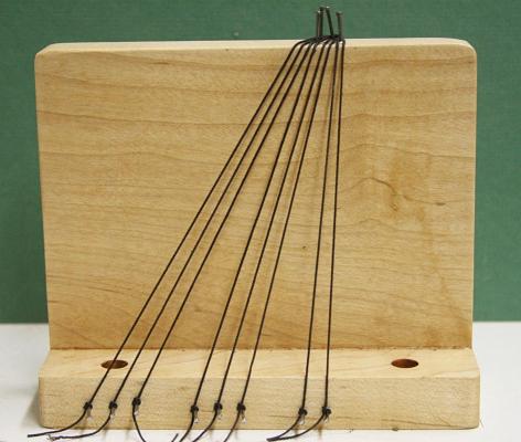
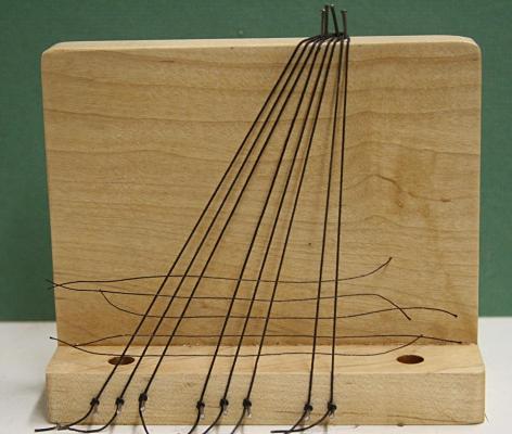
I ran into a snag while adding the rat lines to the futtock shrouds. It is related to my stubborn way of holding off doing this until now. All along I have done well by using needle and thread to punch the rat lines through the shrouds. I would tie this off with a tiny drop of CA glue and trim the ends after the glue is set. The futtock shrouds, however, are hard to get to and in my case the jack spar and other lines made it difficult to use the needle approach. Tying the lines by hand was near impossible. What I ended up doing is to spray some contact glue on the rat lines before hand. I prevented the glue from coating the ends of the lines by covering them with a couple index cards, as shown below. Now I was able to 'glue' the rat lines against the shrouds and come back later to make the joints permanent with a drop of CA glue.
- 732 replies
-
- 2
-
-
- constitution
- model shipways
- (and 1 more)
-
Enjoy. Sending things like this from the US is not cheap! You folks must pay a hefty price when ordering things from here. I know the same goes for the rest of the world, of course. By now Steve you are well aware of a few hints when starting to put the frame, hull and all the other pieces together: Go slow and be sure that you understand the why and how before gluing things together. Dry fit!!! When you lay out the bulkheads and center frame, be sure that they fit snug but not tight. Use files to do this for the sides and bottom of the slots. It is vital that the lines match, otherwise the frames do not come together to make a smooth deck and hull. Check and double check. I'll have lots of other suggestions later.
- 732 replies
-
- 2
-
-
- constitution
- model shipways
- (and 1 more)