HOLIDAY DONATION DRIVE - SUPPORT MSW - DO YOUR PART TO KEEP THIS GREAT FORUM GOING!
×


Modeler12
-
Posts
1,716 -
Joined
-
Last visited
Content Type
Profiles
Forums
Gallery
Events
Everything posted by Modeler12
-
 You've got it. Just send me an email with address, etc.
- 732 replies
-
- 2
-

-
- constitution
- model shipways
- (and 1 more)
-
I came across the CD called 'Building the Constitution, Sophomore Course', the 'practicum' that got me started. I bought this some time ago and it probably is still valid. But I have no longer any use for it. So it is free of charge to anyone who wants it. Send me an email with address, etc. and it is yours. Keep in mind that this is not a copy, paid for and mine. So there is no problem giving this to you. What you do with it is your decision.
- 732 replies
-
- 3
-
-
- constitution
- model shipways
- (and 1 more)
-
Great work Bill. You worked hard and did a beautiful job in one year or so. Now you can enjoy the results by stepping back and recall all the details. I am sure your family and friends all admire this piece of art.
- 335 replies
-
- 1
-
-
- Constitution
- Mamoli
- (and 3 more)
-
Good question, Bill. When I started to make the hull of the deck boat, I ran into a problem sanding the hull too thin. That is why I decided to make the cover and 'cover up' my inside mistake. For the same reason I had the thin side of the hull on the starboard side of that boat and it did not look right. Since the whole ship will eventually be against a wall with the starboard side facing out, I decided to mount the deck boat the way it is. Now it looks too overbearing and later I will make a whole new deck boat. It is easy to get to so that should not be a problem except more time to do it right. Now I know that it will be a very visible part of the whole display and to have a nice detailed boat would be best.
- 732 replies
-
- 2
-
-
- constitution
- model shipways
- (and 1 more)
-
You know, on hind sight you may be right about the instructions Mr. Hunt put together. They certainly were useful to me when I got started. Yes, there were several points where I took a different approach, but all and all I am not sure where I would be with this model if it had not been for this 'practicum' and the forum that he had going at that time. It kept me going. The interactions with others on that forum were great and they are a bit like it is on this forum. The main difference was that Mr. Hunt did not like it when I suggested alternative ways of doing a few things. He made it very clear that criticism was not allowed (and that certainly is not the way a 'college' is run; hence my dislike of thinking of his instructions as being a 'practicum'). When I did make some snide remark, he became unglued and send me an email with language I have only heard on R-rated movies or in West Oakland. Since I was one of his 'customers' I thought he was out of line. I finally told him to take me off his forum and delete my inputs. I am starting to make a list of my suggestions about how to build the USS Constitution model. There will be many areas that are not detailed like Mr. Hunt has, but the approach will be more in line with what I consider 'logical'. One example is to leave a lot of the exterior hull details until last or at least not until the rigging has been done. The gun port lids are in the way and are prone to break, the netting on top of the rails are not to be installed until later, etc. Another is to leave room to belay the lines coming from above by holding off with the shrouds and other lines that are belayed along the outside. In other words, work from the inside out (and from the top on down). Radical? Maybe, but it has worked well for me. I still have some main and fore mast shrouds and ratlines to rig (they have been hanging there for quite some time). I could not have installed the Bentnick shrouds if all the ratlines were already there. My whole concept is to think way ahead of every step and consider the difficulties an addition may impose on installing subsequent parts. Again installing the netting on top of the rail before adding masts and rigging is a good example of what not to do.
- 732 replies
-
- 5
-
-
- constitution
- model shipways
- (and 1 more)
-
Is a waterline marker useful?
Modeler12 replied to CharlieZardoz's topic in Modeling tools and Workshop Equipment
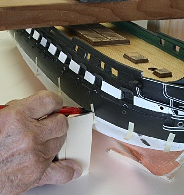
In my opinion the type of marker is not as important as setting up your model such that the waterline is parallel with the table on which it sits. In other words the waterline at the bow and stern should be at an even height. Likewise the line should be the same on both sides. This requires propping up those points until they are at the level as defined in the plans. Below are two pictures showing how I did this with my Connie. The table top was level, hence the sides could be leveled as shown. The fore and aft points were located and you can see the small wooden shim towards the bow. I put small pieces of masking tape on the hull, made a wooden block to the correct height and used that to make my marks.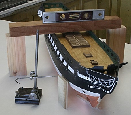
-
how to work with teeny blocks???
Modeler12 replied to achuck49's topic in Masting, rigging and sails
Here is another way to use a clamp or hemostats to hold the block while attaching a line around it. The video is primarily intended to show what seizings are all about but it also shows how I hold the block. I have five of these clamps (some with a curved end) and have adjusted the gap by carefully bending one of the handles using a vise. That way I can clamp parts of various thicknesses. Shop around and you can find them at lots of different places for a couple dollars each.- 49 replies
-
- 14
-
-
Attaching blocks and other rigging to masts and spars
Modeler12 replied to achuck49's topic in Masting, rigging and sails
Have a look at the following Youtube video: When you see a line going through the end of a spar or the top of a mast, It usually means that it represents a sheave inside the spar/mast. The line should be loose and slide through this hole. Sheaves can also be in the side of gunwales. The sheets of the large sails come from above outside the beam of the ship and are led down through a sheave back inside the ship where it is lashed to a cleat or pin. -
One more thing about Mr. Hunt and his instructions about this model. He has built this model and used some nice techniques which he presents in his 'practicum'. The instructions are very useful for those who have never built this kind of model (or any other of this type). However, to pay $300 for that is not very wise! At least in my opinion. The instructions that come with the kid leave a lot to be desired, to be sure. Help is needed. But if you go over the built logs of some of us, and take notes, you will see lots of ways to do the same thing Mr. Hunt suggests. The drawings that come with the kit are marvelous. I never bought the rigging plans from Mr. Hunt and used the drawings of the kit to learn, plan and put into effect my 'rigging plan'. I made many mistakes, learned a lot and will continue along that path!!!!
- 732 replies
-
- 2
-
-
- constitution
- model shipways
- (and 1 more)
-
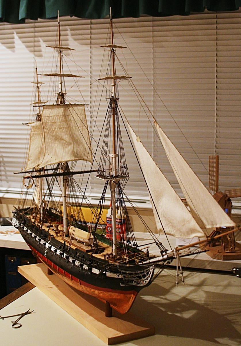
Thanks George for those comments. Yes, it has been a while since I worked on my Conny and it is high time to get going again. I am continuing to work on the rigging. The topsail for the main is now in place and I will soon begin on the fore-topsail and fore-jack. There are still a lot of other details to keep me busy (such as the Bentnick shrouds etc.). What I like to do soon is to put together a summary of this built (although not finished, I can see the end on the horizon). I learned a lot and would like to pass my suggestions on to others such as you. The USS Constitution is not the most complicated of the period ships, but it does offer a lot of details that are applicable to models. Here I must make mention of the tutorial that I bought from Mr. Hunt which was a great help. He had some nice suggestions about how to start the frames, etc. But I made many changes (improvements?) to his ideas as I went along. His forum is lo longer active, but it was a good way to exchange ideas with others who were building the same model. Too bad Mr Hunt and the forum turned sour. But there are several other members on this forum who have done a marvelous job with their Conny and contributed a lot of good ideas as well. Below is a picture of where I am now. Nothing new but lots of lines, knots and mistakes.

- 732 replies
-
- 8
-
-
- constitution
- model shipways
- (and 1 more)
-
CA glue question
Modeler12 replied to MikeB4's topic in Building, Framing, Planking and plating a ships hull and deck
This is an interesting discussion. I assume that using both adhesives results in a faster set-up time (with the CA) and still get the advantage of the superior strength of the PVA glue, right? Would you let the CA 'dry' before joining the two? Or do they combine pretty well while both are still 'wet'? Does this give you the quick set-up time of one and the strength of the other? I know that CA 'loves' moisture but I am still curious about the 'love' affair between the two (speaking chemistry, of course). This is a whole new dimension!!! -
This is true to some extend. However, we should not confuse 'pot life' and 'cure time". What I mean is that pot life is a rough measure of how long it takes for the mix to start gelling. The actual cure starts slowly and takes many hours to complete. Parts should remain clamped or at least not be disturbed while the epoxy cures. The '5 minute stuff' is typically a two part epoxy (resin and hardener) and has a pot life of a few minutes. It still takes at least several hours to fully cure. In fact 24 hours is better. I have also used epoxies that have a pot life of several hours (depending on ambient temperature). And these also require a full 24 hours to cure at room temperature. The advantage is that you can move things around for some time and use the mix for several applications before it starts to solidify and cure. One more suggestion: for small applications I squirt about equal parts of resin and hardener on a piece of scrap wood and mix them with a toothpick. A round toothpick is also handy as an applicator. For hard to reach places I have a clothespin holding the toothpick.
-
Constitution. Mystery rigging in top
Modeler12 replied to JerseyCity Frankie's topic in Masting, rigging and sails
Popeye2sea did it again. The truss tackles (P and S) seem a bit awkward at first glance, but they serve a good purpose (holding the jack close to the mast). When I came to this part on my Conny I debated about adding them, but a closer look at their purpose made me go ahead and add those lines, blocks, etc.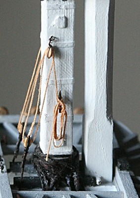
-
scroll saw troubles
Modeler12 replied to michaelpsutton2's topic in Modeling tools and Workshop Equipment
There are a number of blades for scroll saws and the one that comes to mind is the spiral blade shown below. I have never seen this on a table-saw blade. There is also a 'blade' with an abrasive or diamond coating around a wire that can be used to cut ceramic, etc. This could be similar to an abrasive cut-off wheel for a table saw.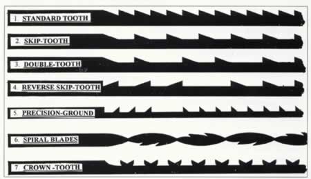
-
scroll saw troubles
Modeler12 replied to michaelpsutton2's topic in Modeling tools and Workshop Equipment
I agree with Bill. The blade could be your problem, not the machine itself. If the teeth are duller on one side, the result is a curved cut. I suggest you try several new blades and see what the difference is. To verify what Bill and I are talking about, take one blade, make a cut, then dull one side with a stone and see how it cuts using the same material. -
I have used poplar a lot for various wood working projects. I am now starting to use it for the frames of my next model. To see some details, go to http://modelshipworld.com/index.php?/topic/2191-hms-pelican-by-modeler12-per-harold-hahn%E2%80%99s-plans/
-
I think that the air in the bottle reacts with the paint. So, at least with larger cans (quart etc), I add some clean rocks to the can and minimize the amount of air that gets trapped inside. With small bottles you can do the same using beads or other small, inert stuff.
-
Sorry, I know I am a bit slow. But can you repeat this with a picture? I think you are saying that to use the broken blade in the 'down cut' position, or reverse mounting gives you better control? The idea of using part of a broken blade as a small tool in an Exacto knife, for example, is neat. I will try that, but you still should go 'up and down' to get the benefit of the saw. So the finer the teeth, the better?
-
I just got back from a week vacation, but here is my understanding about what you are referring to: The catharpins were used to tie the upper shrouds (coming from the topmast and down through the 'top') to the main shrouds. However, it was better to distribute the load on those shrouds to the other side. Hence, these lines did just that. I know this is confusing to read and that is why Petersson's pictures are so much better. But the upshot is that if there are only five upper shrouds, you only need five catharpins. I don't know this for a fact, but I would assume they are tied to the forward shrouds (all others are too far aft). You take it from there???!!! The Bentnick shrouds were a bit more complicated in-that they took the load on the upper shrouds down to the deck (instead of going across to the other shrouds). I don't believe Petersson's book shows that. Then there is a third way and that was to tie the upper shrouds (below the 'top') to the main shrouds. This eliminates the catharpins and bentnick shrouds, but that puts all of the load on the main shrouds. And that is not fair???!!!
- 732 replies
-
- 2
-
-
- constitution
- model shipways
- (and 1 more)
-
Hi Chief. I was wondering if you could help me with a couple words you bring up. What is 'suply' and 'armature' as it relates to carving? I assume that armature is the support frame that holds a clay molded figure together. Is suply the clay?
-
Lennart Petersson's book is a great source. To get some ideas go to the abbreviated version on the web: http://www.all-model.com/Rigging-1/Rigging%20period%20ship%20models.html Then click on any of the drawings that look of interest.
-
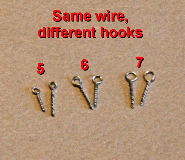
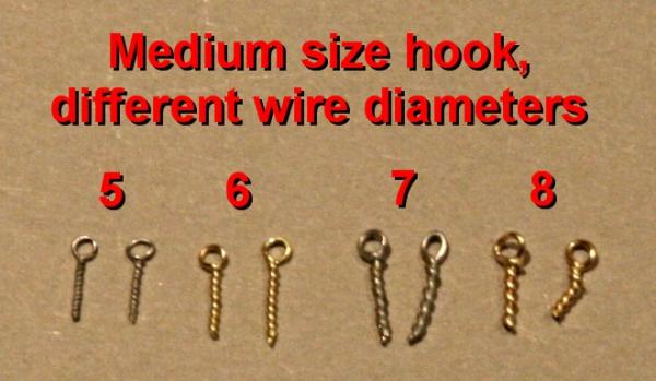
In an earlier thread we discussed making eye-bolts by twisting the wire using a thin brat held in a pinvise. http://modelshipworld.com/index.php?/topic/6185-in-need-of-very-thin-steel-wire-0010-inch-or-less/?hl=eyebolts#entry182571 That led me to try different types of wire and hooks. I wanted to see the results and which would be the best to use to make in large quantities. I also wanted to see what the eye size and shaft diameters were and see how that relates to actual full scale sizes. Can I make them consistently of an acceptable shape? The wires I used were as follows: Soft steel at a diameter of 0.010 inches Brass at a diameter of 0.013 inches Soft steel at a diameter of 0.015 inches Brass at a diameter of 0.016 inches The brass was semi hard and I did not anneal them. They came from a craft store and probably had a polymer coating. The steel was bare and very malleable. I used hooks of three diameters: 0.022 inch, 0.035 inch and 0.047 inch. I twisted about ten of each wire size around most of the hooks and measured the eye and shaft diameters. Some of them are shown in the pictures below. However, here is a brief description of the results: 1. The shaft diameters were a few thousands of inch smaller than two times the wire diameter. For example, using the 0.010 inch wire, the shafts were all between 0.018 and 0.019 inches. 2. The eye diameters were a few thousands of inch larger than the hook diameter. 3. The thicker wires were more difficult to twist and not very uniform. Let's consider the scale. For a model scaled at 1:64 the actual eye diameters would have been about 1.5 inches, 2.3 inches and 3.2 inches. The last one is getting pretty big. The wires would scale to 0.6 inches, 0.8 inches, 1.0 inches and 1.0 inches rounded off. The first two seem reasonable. Because of this and the relative sizes of wire and eye I will be making more using the thin steel wire with the small hook and the .013 inch brass using the medium size hook (0.035 inch). All of these will be blackened. Meanwhile I will also order some brass wire at a diameter of 0.0073 inches to make even smaller eye-bolts.

-
Oh wait, Jeff. I did not vote yet on this. Please give us a week or more to see this and reply
-
Dave, although there are vast numbers of members here, not all review these topics on a regular basis (if ever). These surveys are brand new (a couple days) and it would be imprudent to expect total input this quickly. Hold your horses, both of you, please. My first reaction when I saw the first 'survey' was: Ah here we go again with one of those. Now I feel a little differently about this and I am curious what other members think about some of the questions and how they are answered.
-
Rather than an absolute, I would assume you would go along with 'remarks' when ordering. It would give us and you a way to order 'random lengths, but not shorter than . . .', widths somewhere between x and y (meaning that I would cut the wide strips to what I need anyway), and other specifics that would help you and the price.