Modeler12
-
Posts
1,716 -
Joined
-
Last visited
Content Type
Profiles
Forums
Gallery
Events
Everything posted by Modeler12
-
I agree that Chuck deserves a lot of our business and he offers great products. But that means he might increase his prices too much How about others? Just to keep things on an even keel.
-
 That is a great spot and will be a beautiful addition to your home, Bill. Besides being a modeler you are also a great woodworker. I hope your admiral thinks highly of you.
- 335 replies
-
- 2
-

-
- Constitution
- Mamoli
- (and 3 more)
-
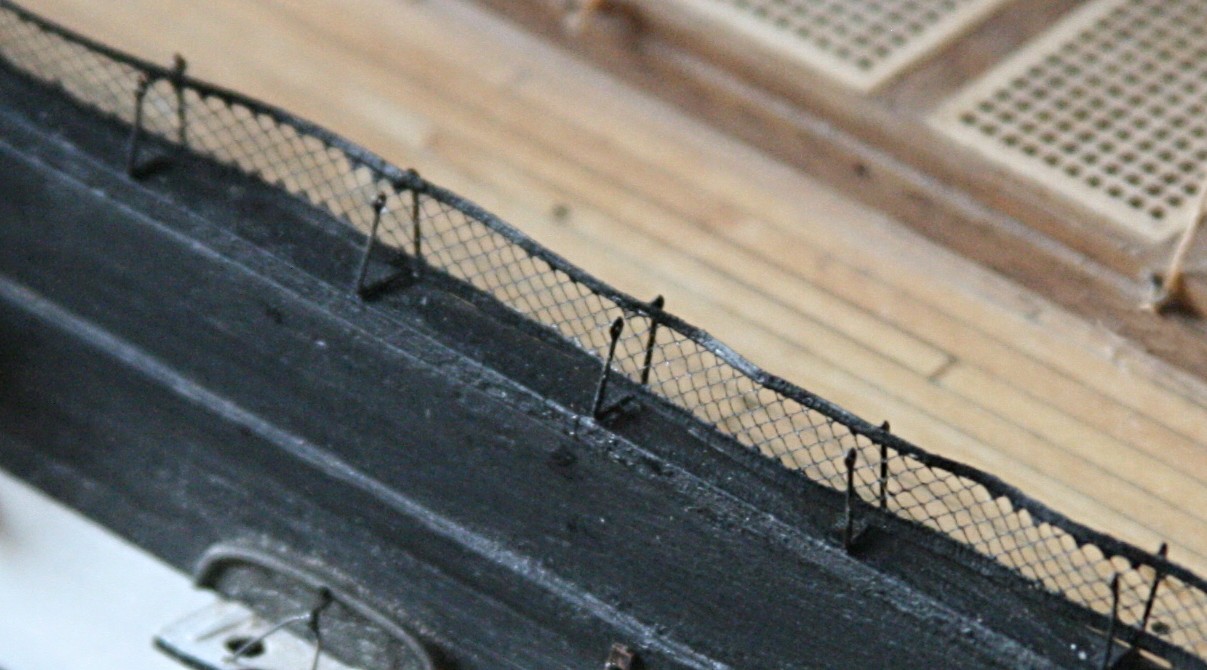
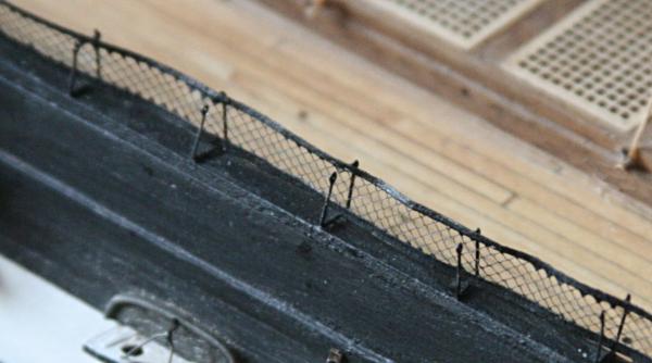
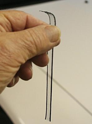
You know, George, that is not a bad idea. Instead of the piece of wood I mentioned, hammocks make more sense. With this and Bill's input above, I have to rethink this whole thing. I am still continuing to make those nettings, but will hold off installing them until I can figure out a nice way to make hammocks. To have a 'rigid' inside (smelly, sweat stained lumps of canvas) would make installing the netting to the outside a bit easier. Thank you guys for keeping me thinking. I love those inputs. Let me add the picture below of my first try to install the netting on the inside. It is far from pretty and I will have a heck of a time with the rest.

- 732 replies
-
- 7
-
-
- constitution
- model shipways
- (and 1 more)
-
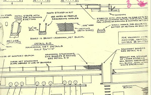
Thank you Jim for that comment. As you may have gathered, I am rather verbose and love to include pictures whenever possible. Quite often I see things in those close ups that I would have missed otherwise. It is also a good record of what I actually did (a couple years ago, for that matter). Bill, I will put the netting inside the stanchions if at all possible. I did one and it is hard on my clumsy hands. I am also using a piece of thin wood to go inside between the two nets so I can apply a little pressure during the bonding of the second strip. No photo yet. But here is a copy of part of plan #4. There are actually lots more details on that page. The drawing does show the netting on the outside, but all the pictures I have seen of the actual ship in Boston, has the netting on the inside. Considering that the hammocks would be stuffed in between the two, having the support inside makes more sense to me. Notice the details about using .005 inch wire and all those small hooks on the rail. No way for me.
- 732 replies
-
- 2
-
-
- constitution
- model shipways
- (and 1 more)
-
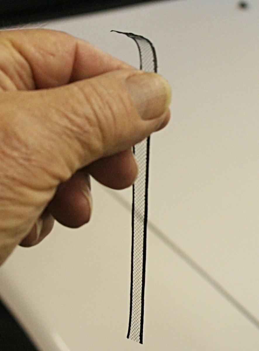
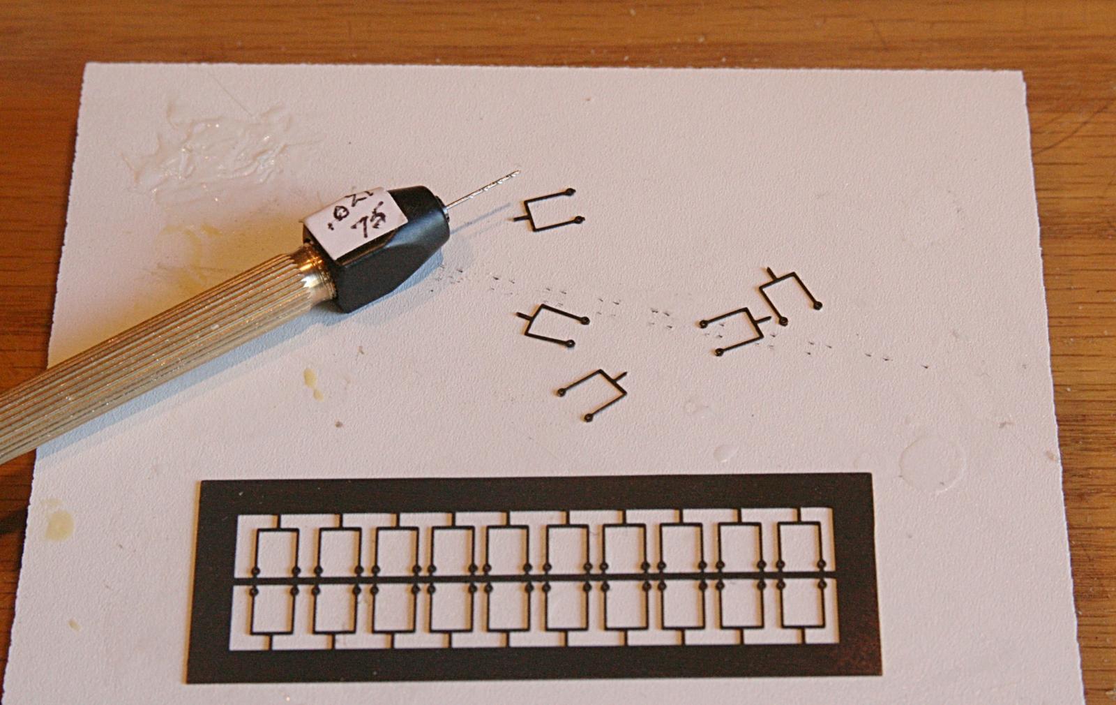
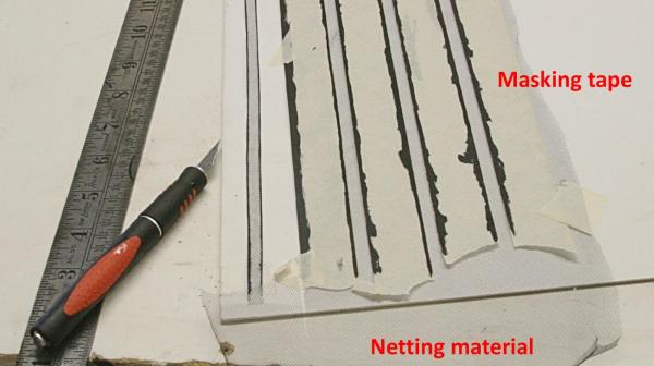
Here is how I made the netting. Mr. Hunt's idea is great, but he did not explain in detail how he made it except to say he used masking tape on top of the netting material. The pictures below are just for my records. I took the black mesh (from a fabric store), smoothed it and held it with pieces of tape on top of an old piece of matting board. Then I stretched strips of masking tape on top of this, keeping the edge as straight as I could. The second piece of tape was next and spaced just under 1/4 inch apart. To stiffen the edge I went ahead applied the black paint. Using a very sharp blade in my knife and a steel ruler, I cut through the tape and netting such that there were very narrow strips of tape left on the netting. Then the back side was painted also. The result is a strip that is very fragile and feels like a wet noodle. The black paint helped, but not very much. Now comes the tricky part. Installing this inside the stanchions, one on each side of those little guys.
- 732 replies
-
- 5
-
-
- constitution
- model shipways
- (and 1 more)
-
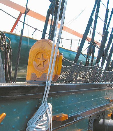
Thanks JS. Nice pictures and do help to see what the netting looks like. It is my understanding that the wooden rail is there for the visitors and was not part of the ship's 'furniture'. The netting there is also much higher. Probably also to keep little guys from getting hurt. My guess is that this area would be kept low since cargo and the large pinnace would be going through this spot when brought aboard. I also got a kick out of seeing the studding boom lashed to the hull and the brackets that hold it there.
- 732 replies
-
- 1
-
-
- constitution
- model shipways
- (and 1 more)
-
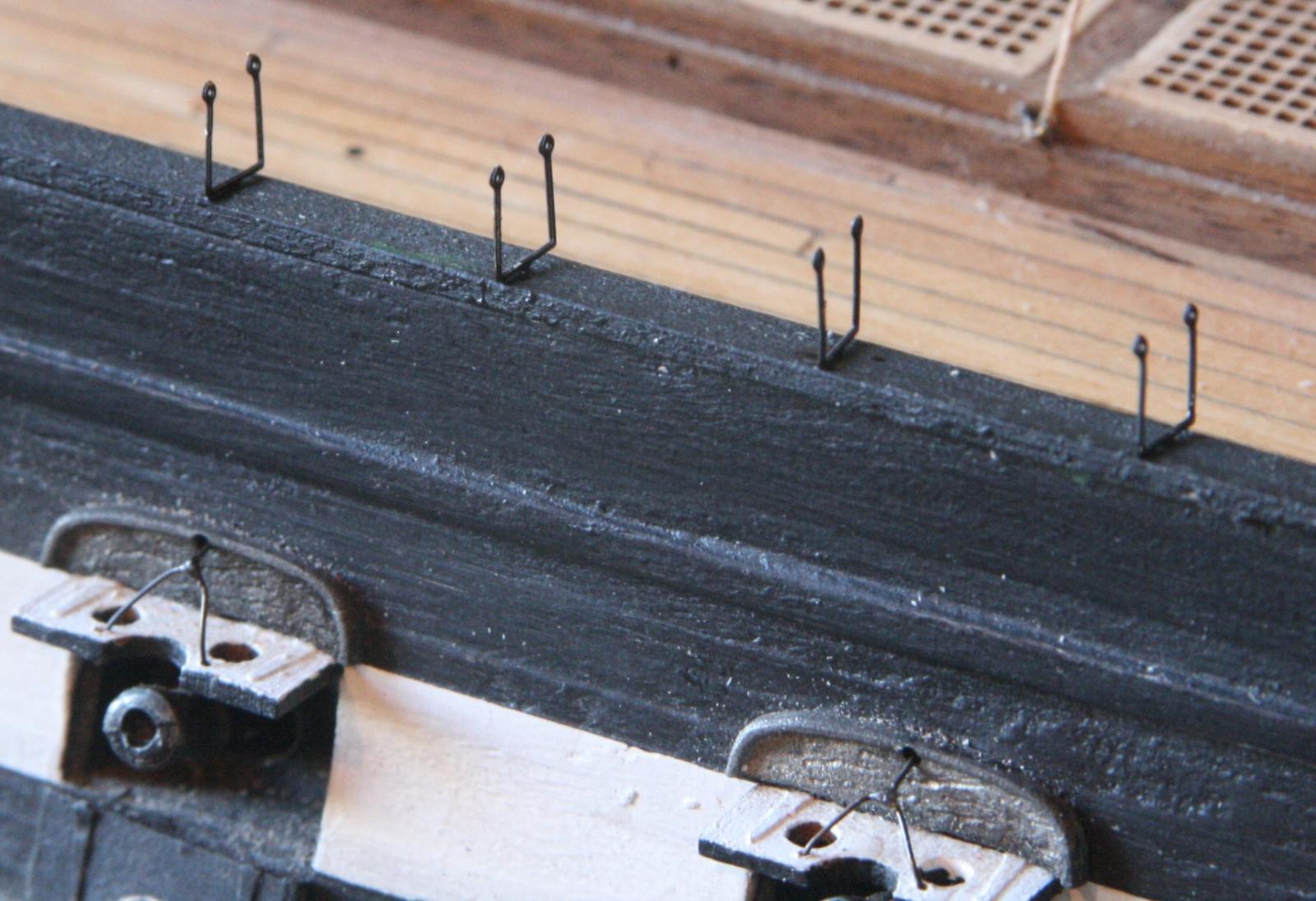
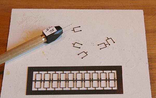
Installing the netting on top of the rail is delicate work as well as for the final product. That is why I held off as long as I did. First come the stanchions. They are provided in a sheet as etched parts. Here is a trick that I learned when putting the hinges on the gunports lids. Don't cut off all the trim; use it to hold or install. In this case I left the long piece attached to the bottom of the stanchions and drilled a hole in the rail to keep it in place with a drop of AC. I'll be making the netting as Bob Hunt showed in his practicum using masking tape on top and bottom instead of the wire that the plans call for. In fact, the plans are so detailed with tiny hooks, etc. that I think it would be almost impossible to reproduce the actual.


- 732 replies
-
- 3
-
-
- constitution
- model shipways
- (and 1 more)
-
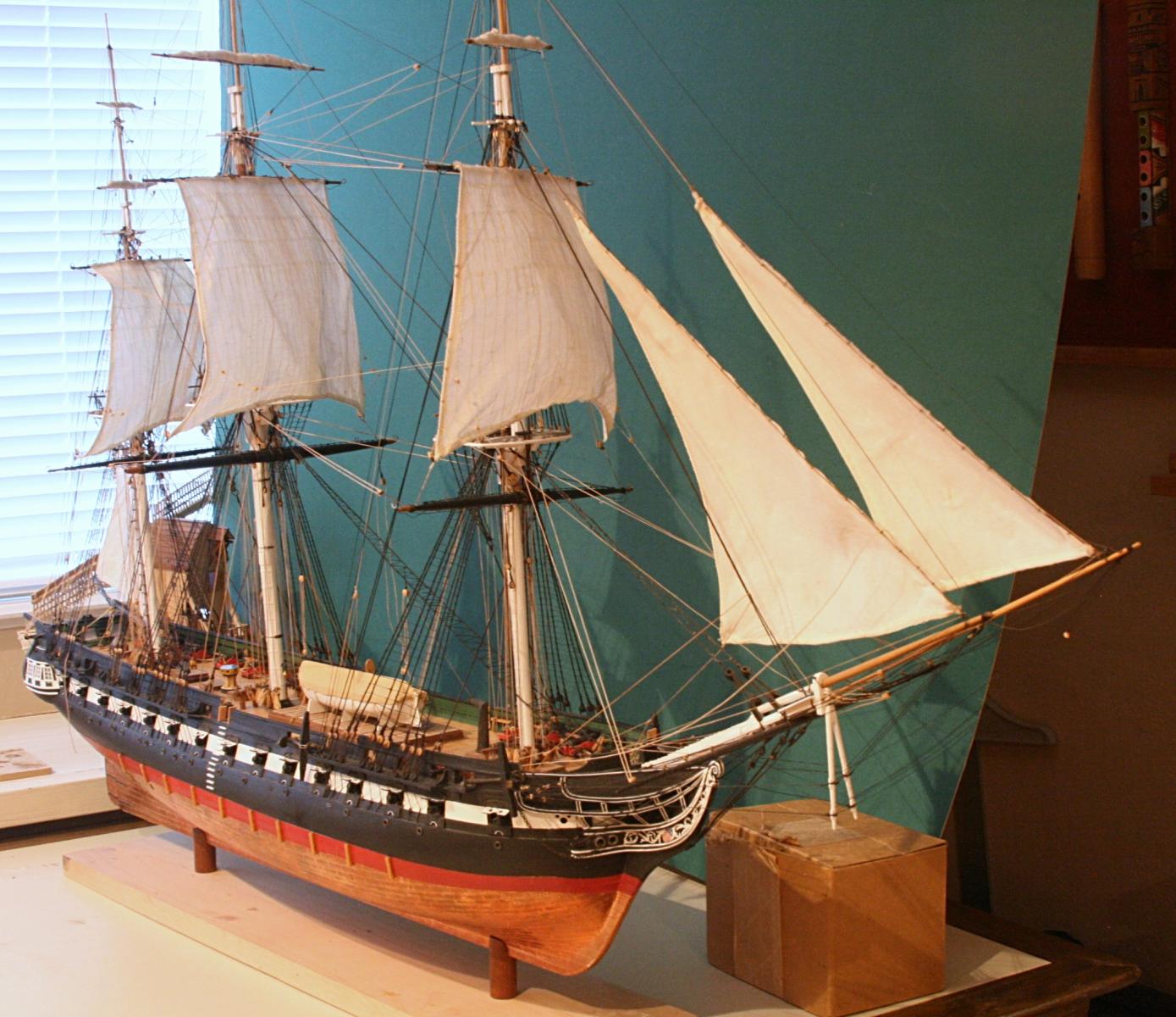
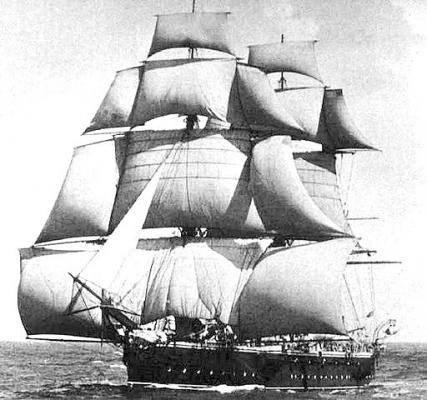
Thanks Harvey, it reinforces what I have learned in the last few days from all of the member's input. In fact, when I look at the first photograph above, how can anyone argue that the lower fore studding sails may take all or most of the wind? With a wind direction from around six o'clock, a studding sail aft would cause some steering problems, I am sure. It reminds me of difficulties when a spinnaker sail goes too far aft on a modern sailing boat.
- 732 replies
-
- 3
-
-
- constitution
- model shipways
- (and 1 more)
-
Thanks Bill. That also helps to clarify where that main boom was stored. As others have said, the use of the fore mast lower studding boom was predominate and I am not aware of pictures showing that the lower main studding sails were used or in place. But I am not an historian about a lot of details. I will leave the subject of studding booms as it stand now. BTW you have one beautiful model, my friend. I am following your progress with the display case with great interest. For mine, I have put the drawings together and am ready to start buying oak and make some sawdust. It has been a while for that.
- 732 replies
-
- 3
-
-
- constitution
- model shipways
- (and 1 more)
-
Silver soldering - Copper vs Brass
Modeler12 replied to rtropp's topic in Metal Work, Soldering and Metal Fittings
I agree with Mark. It could be the solder. I have used 'Solder-it' for lots of brass and copper joints and after some practice had no problems like you describe. For more details go to http://modelshipworld.com/index.php/topic/1888-silver-soldering-tools/page-2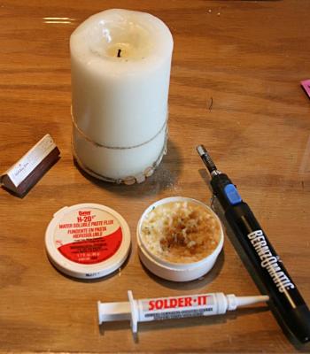
-
Studding booms, how are the lower booms attached?
Modeler12 replied to Modeler12's topic in Masting, rigging and sails
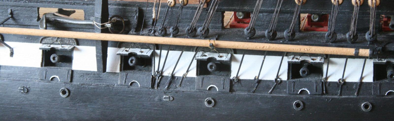
Steve, this is the part that I am referring to. The lower studding sail boom is what I show for the fore sail. It hinged by way of the pin in the end of the boom and was lashed to the side of the hull when not in use. It is a long pole and would not easily be stowed below deck. So, where is the one for the main studding sail? Or was there never a lower studding sail for the main? Petersson and Marquardt show those sails on the plans, but do not mention where the booms are stowed. Evan, I am going to assume (as you mentioned) that there was no lower main studding sail on the Constitution. If other ships did have them, the boom was probably lashed to the side of the hull like the one for the fore mast. -
You know, Harvey, that makes a lot of sense and I will go with that. Here are a couple pictures that show exactly what you are referring to. Nevertheless, both Marquardt and Petersson refer to a 'main lower studding sail' as well as the 'fore lower studding sail' as if the two are at the same level. Just curious.
- 732 replies
-
- 2
-
-
- constitution
- model shipways
- (and 1 more)
-
Studding booms, how are the lower booms attached?
Modeler12 replied to Modeler12's topic in Masting, rigging and sails
John, my picture is not very clear, but mine also has that pin. That is why I mentioned the eye bolt into which it fits. That was actually the swivel point for the boom to extend it out away from the ship when needed. My log has more details. But the question is more related to what happened to the studding boom for the main. -
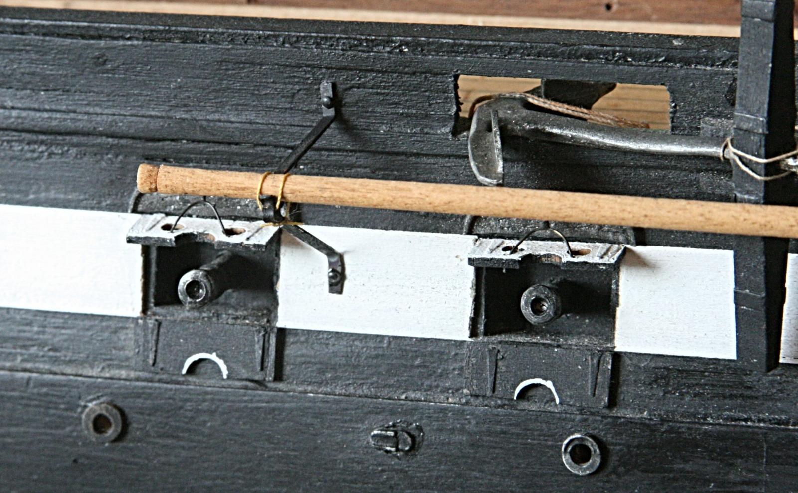
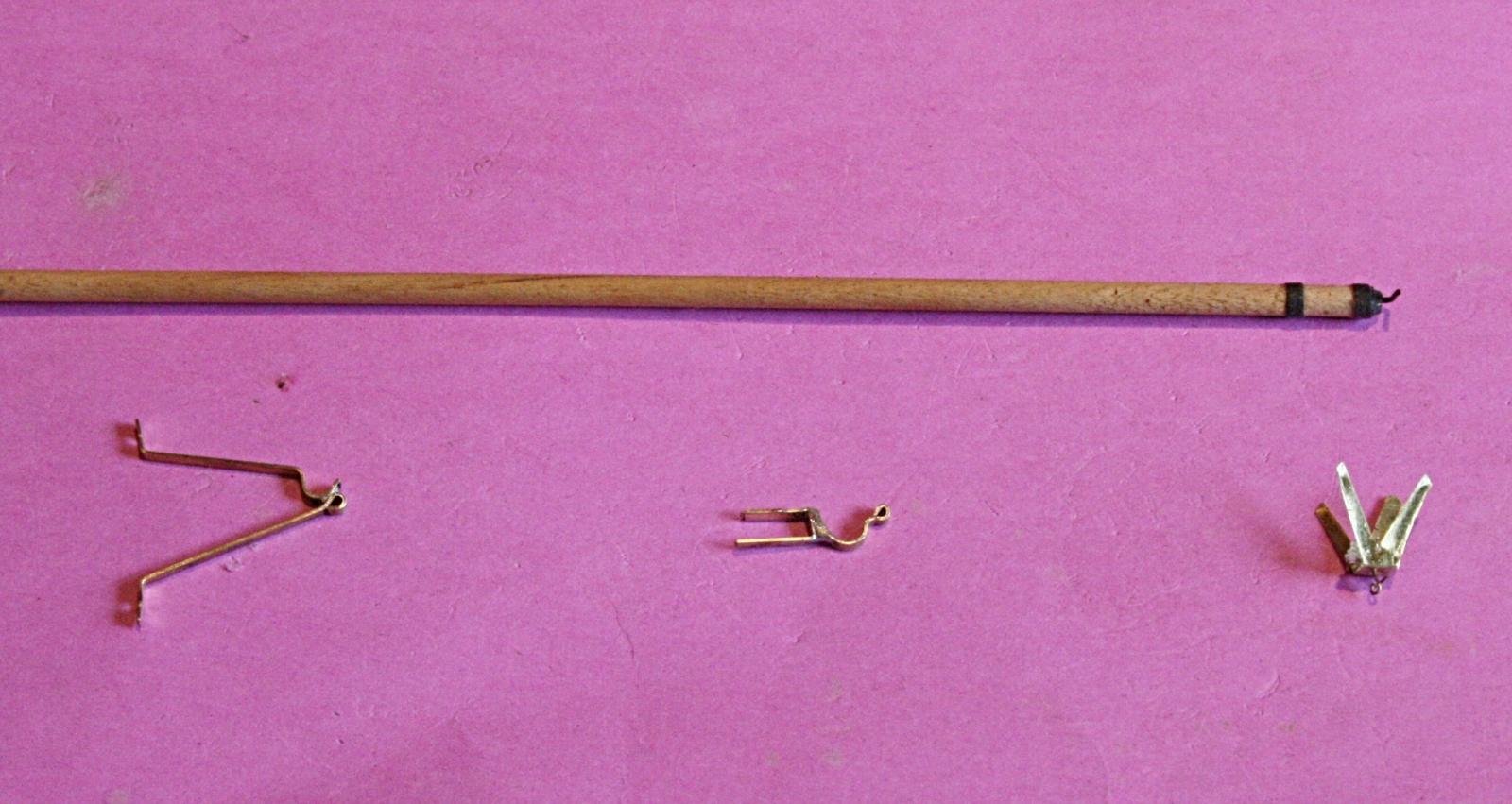
On my USS Constitution the plans are a bit sketchy about how the studding booms for the lower sails are attached and used. After some scrutiny it turned out that the details are there for the fore mast sails. See below: What is not clear to me is how and where those booms are stored for the main? I am, of course, referring to the lower studding sail booms. I may have to look at my reference books, but I don't think they talk about that

-
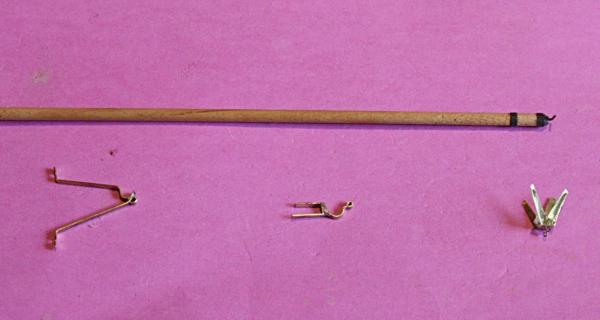
I must admit that I made the one at the right a lot more difficult. I tried to mount the eyebolt as part the fitting (hence my use of epoxy). What turned out to be a lot easier is to install the fitting without the eyebolt and after that is all aligned (using the boom to be sure the three are ok horizontally) then add the eyebolt by drilling through the fixture and channel. Use epoxy at this point to add the eyebolt as a separate piece. Because the eyebolt I installed actually broke; that is how I ended up doing it over again. FYI I used some 5 mil thick brass to cut out the X and drilled a hole in the center of the X. Then I bent the legs to fit around the channel. The spacer inside could be anything, as long as the whole thing lines up. One thing is not clear to me. This boom served the fore mast studding sails, what about the mizzen and main studding booms? I guess they were stored until needed. Question for the general forum?
- 732 replies
-
- 2
-
-
- constitution
- model shipways
- (and 1 more)
-
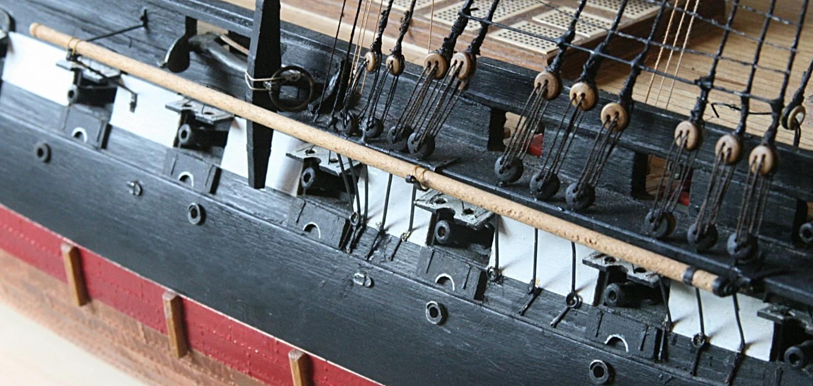
I almost forgot. The studding sail booms. Quite some time ago I made the two studding booms that have the fancy name 'Fore Lower Swinging Studding Sail Boom'. They mount along the sides of the hull with brackets that hold it against the channel and hull. The three brackets are shown below. The one on the right has an eyebolt (epoxied in place) where the hook of the boom fits. The other two have saddles (silver brazed). Since the boom is tapered (left end not shown) the saddle of the left bracket is smaller. Once the epoxy is completely cured that part will be cleaned up and trimmed. Then all three will be blackened and the boom mounted to the hull. Two of the brackets have eyes for the lashing cords. What about the other studding booms? When I made the spars I did include the loops on the end of the spars as well as the one further inboard. However, I am not sure I want to attach the booms. The whole thing is busy enough and studding booms were not used very often. The two along the hull, I think, will add some pazzaz.
- 732 replies
-
- 3
-
-
- constitution
- model shipways
- (and 1 more)
-
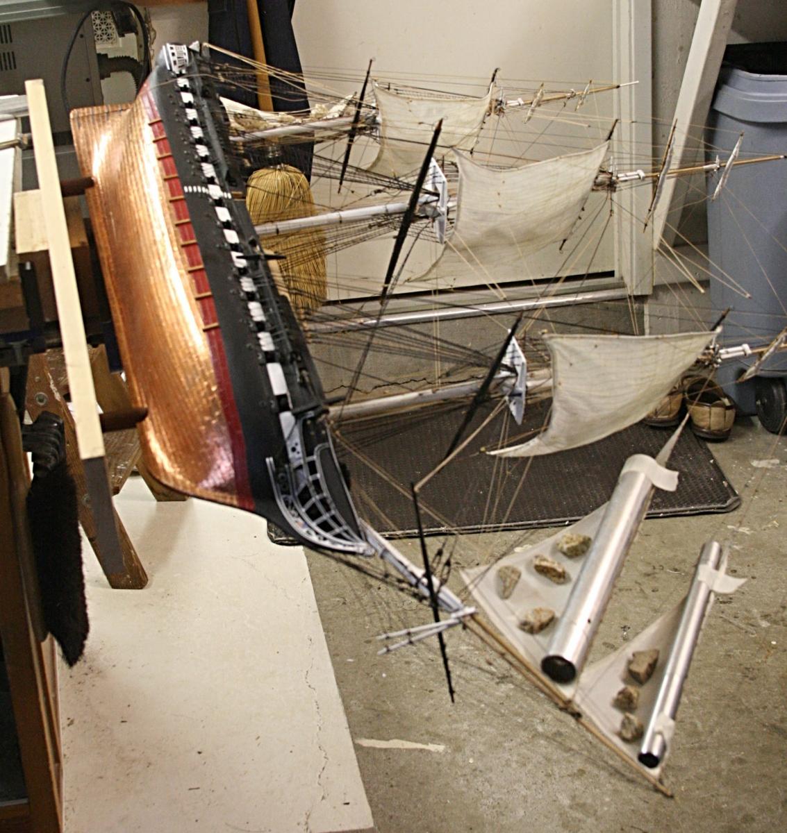
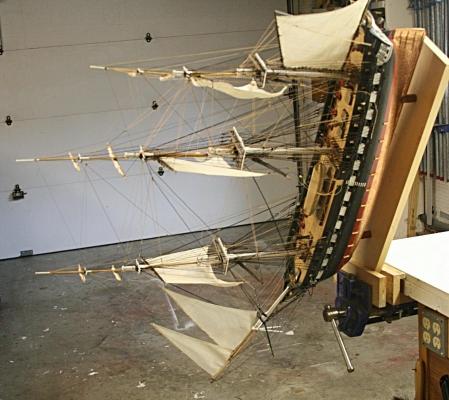
I used two metal bars with two bolts to clamp my hull until the copper sheeting had been applied. It is similar to what Captsteve shows above. From that point on I mounted the ship on a wooden board with the posts in place that will hold the ship in its final position. It is a very rigid support that allows me to handle the whole thing without worries of coming loose. The board has taken a lot of abuse and will be replaced with a better looking one when the ship is finished. The picture below was taken when I made some adjustments to the sails. I have a lazy Jay to turn the ship around
-
Here is some information about the copper tiles. You might be able to get more details about the rivets from them as well. COPPER SHEET The duration of time in which Constitution was out of the water required that her bottom be re-caulked. This required the re-coppering of Constitution's bottom. All copper products were purchased within the Federal supply system. Metal Sheet: Copper: 0.032 in thick, 36 in wide x 144 in long approx: 53.28 lb/sht Supplied by: Revered Copper Products Inc. Sub of Revere Copper and Brass Inc. Seneca Street P.O. Box 300 Rome, NY 13440 I forgot, but here is the website: http://www.maritime.org/conf/conf-otton-mat.htm
- 113 replies
-
- 1
-
-
- constitution
- mamoli
- (and 1 more)
-
At one post (#28 I think) you mentioned that some light might be good. Have you considered adding tiny LEDs? It might still be possible for your model. One more question: This is a great project and you are doing a tremendously nice job with the details. Obviously you have done a lot of research and given thought to such things as the barrels. Good for you. Would you do this again using a kit? It would seem to me that (in hind sight) you could have done the whole thing from scratch.
- 113 replies
-
- 1
-
-
- constitution
- mamoli
- (and 1 more)
-
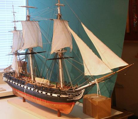
Thanks George and Steve for you comments. Yes, adding sails to this model was a real challenge. Even without sails the rigging is tremendous. Would I do it again? Probably. I have a friend in New Zealand who thought I was crazy to do all that rigging and add sails as well. For me that was another incentive to prove him wrong. As you know there are many, many lines on this ship. That means many, many blocks, eyebolts, etc. I can appreciate the fact that most people choose not to add sails. The extreme would be to add all of them, which I think would be impossible while doing justice to this model. I chose to add the six sails rather than more or less, because it is my understanding that those were the sails most often used during a battle. They also were used when the real USS Constitution sailed the Boston harbor a couple years ago. The gun ports are open and the guns ready for action. The only things missing on the model are the crew and the enemy ship. For me it was a real learning experience about how those ships were rigged. It is a bit too early, but I must thank so many of our MSW members who gave me good advice and suggestions. That kept me going. Perhaps when I am really done, I might go over a few points that I did wrong (or well ). BTW raising the flags will entail adding two more blocks
- 732 replies
-
- 2
-
-
- constitution
- model shipways
- (and 1 more)
-
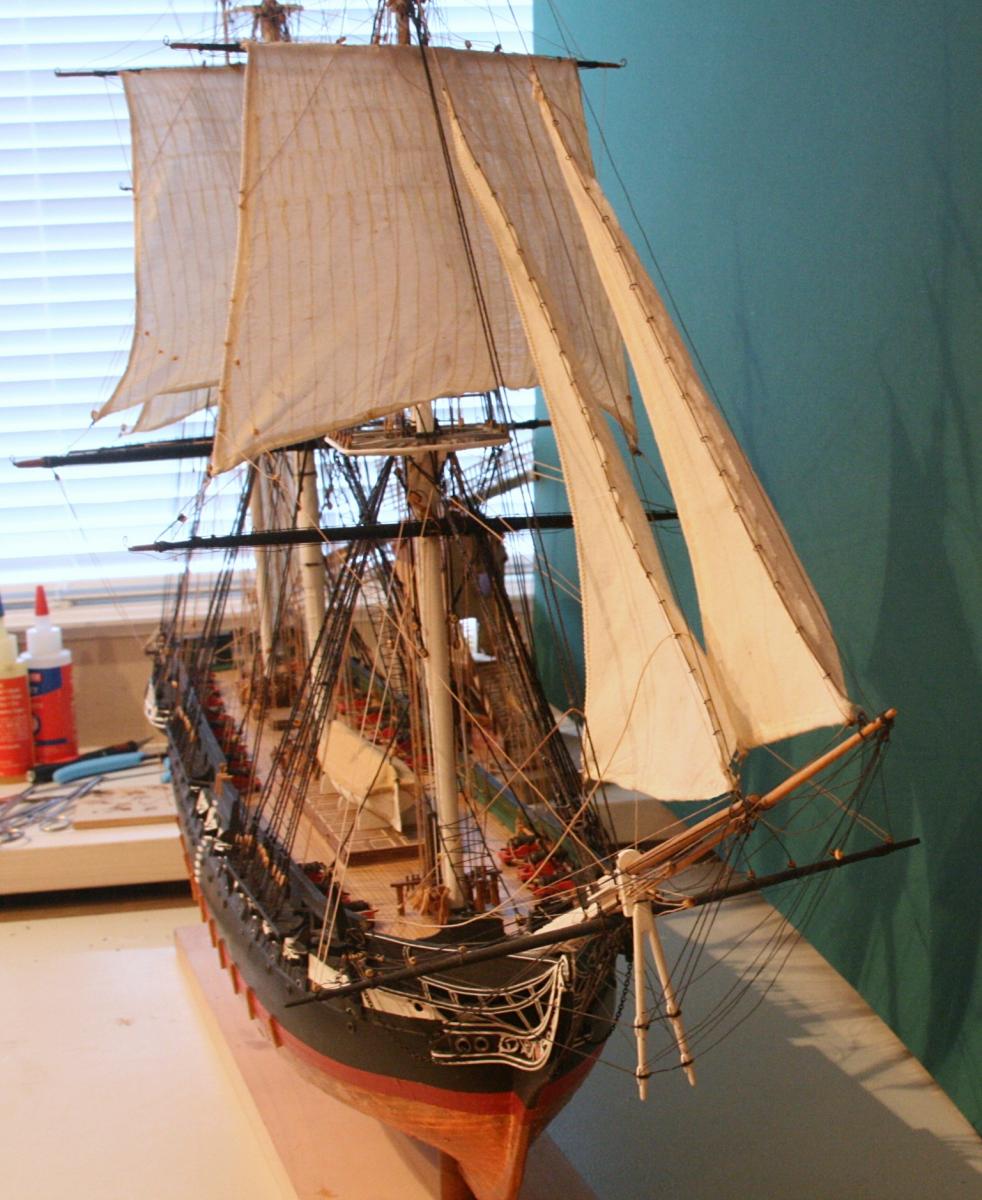
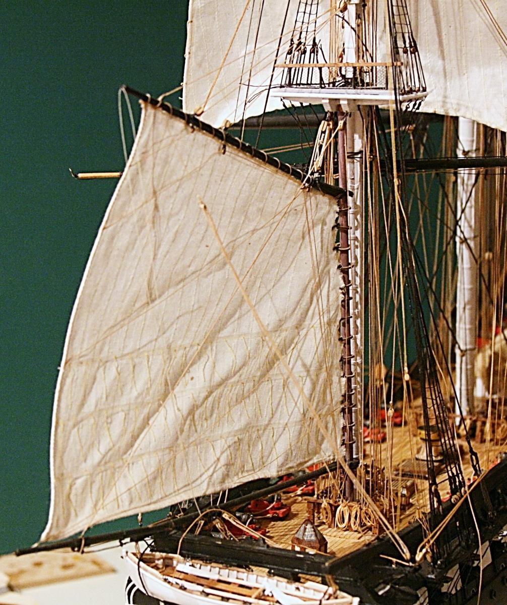
The result was not perfect, but better. It is hard to show the shape of the jibs, but here goes. Next comes the netting on the rails, attaching the boats and finally to raise the flags.

- 732 replies
-
- 10
-
-
- constitution
- model shipways
- (and 1 more)
-
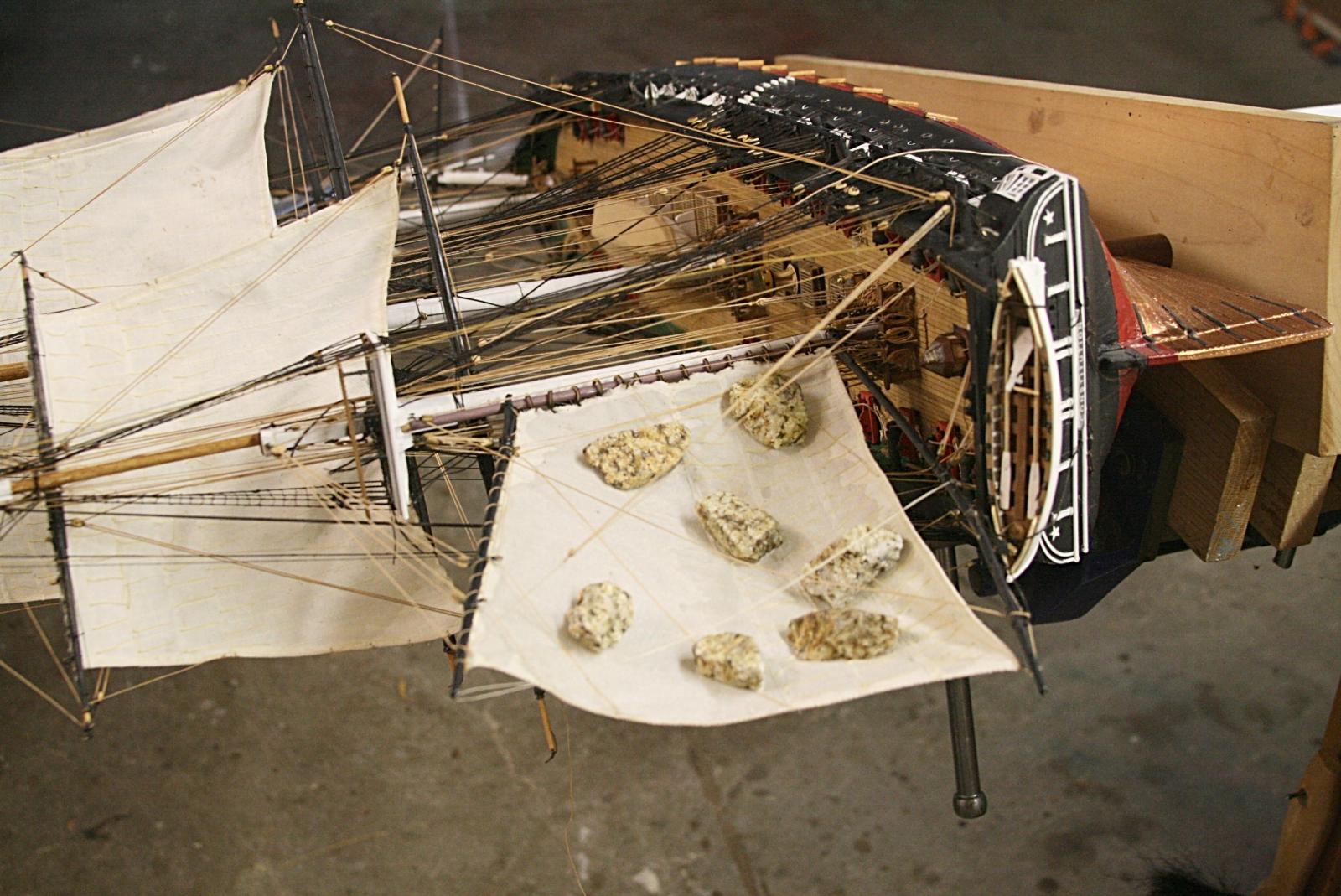
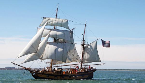
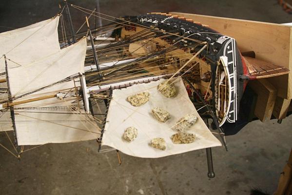
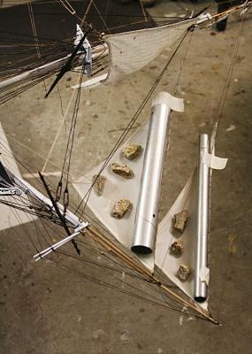
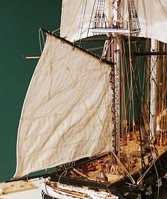
Here are some more pictures of the spanker and jibs. I decided to use some aluminum tubing for the leading edge of the jibs. That way I hope it will look smoother than what I can do with a bunch of rocks. It would be nice to have the sails look like they did on the Hawaian Chieftan when that last picture was taken. I might add here that all my sails have a steel wire in the bottom edge (or foot). It was embedded when I made the seams. That helped to shape part of the sails, but not all of it.

- 732 replies
-
- 5
-
-
- constitution
- model shipways
- (and 1 more)
-
Thanks Tom. And because it worked well, I will do the spanker and jib sails this way also. Fam, when I made the sails I used essentially the method you suggest above. However, I used starch. The problem I had was that the hair dryer was either not strong enough or I did something not quite right. While blowing the hot air into the sails they tended to flutter. This resulted in some wavy shapes. That is why I decided to use the 'static' approach and let the glue cure/dry with the sail in the position I want.
- 732 replies
-
- 1
-
-
- constitution
- model shipways
- (and 1 more)
-
Thanks, George. All I have to do is remount the lady in a vise, level her to my liking and add some white stuff to her aft.
- 732 replies
-
- 4
-
-
- constitution
- model shipways
- (and 1 more)