

Walter Biles
-
Posts
356 -
Joined
-
Last visited
Content Type
Profiles
Forums
Gallery
Events
Posts posted by Walter Biles
-
-
Ron, is there any way to retrieve a view in 3D that unintentionally got closed? Now it is closed I can't figure out how to re-open it. all the data is still in the files, it just does not open that FRONT view. It no longer shows in the Window display of available views.
-
Mark, It was just the 3D Front view. The Side, Top, and Main are still listed in the Windows section. I was being pretty careful not to hit the X button so I wouldn't lose one, but I bumped the keyboard and something else came up. That menu I did want to close, but when The 3D views came back, the Front view was gone. It's like it closed both. Is there anywhere those different veiws are kept? I was using DesignCAD 23.
-
Well, I was making progress. Just as I got the next to last frame put into the new 23 version, something, happened, I am not sure what, and the front view dissappeared. Since I was using that one to check for positioning, and I can't find a way to make it come back, I am stuck. I may have to back up and redo all of them from an earlier save. NUTS
Just another day at the computer. Now just where did those earlier and later saves go? I wish these programs would quit putting saves in some other part of the computer.
-
Ron,
Thanks for showing the stages. I had made the stations mirrored already. I wonder if that would be easier lining things up. I have noticed something called (I think) solid subtract. I still haven't learned to make the hull a solid yet though. There are so many more features that it would be wonderful to learn. I am going to study your drawings for awhile, and see if I can make mine come out like yours. Then I may have some more questions about how to do some things. Thank you so much for your assistance. Having some help like this could make all the difference.
-
Thanks for the Like Mark. I am using this CAD work as further therapy for my mind. I sure hope it pays off. That interference tool is one I am excited about being able to use. That and being able to get the boat into 3D so I can visualize things better. Also, it would be interesting to be able to use the walk through facilities that this program has talked about. That should make some sort of mishap inside show up before I go to the building table.
-
Hi Jond,
I had severe Sleep Apnea until I was forced out of working after my points had been reached. The oxygen deprivation killed parts of the brain and it's links. I have found this exercize to be beneficial once my CPAP treatments got me away from nightly low levels of O2 for most of each night. I have recovered some things that I had once learned. However the damage to my short term memory caused learning something new to be a very hard thing. With exercises of body and mind I have regained many of my old links to old memories. The damage to my short term memory causes great problems.
Since what I try to learn can't stay there long enough to get to my long term memories. My math skills which used to be very good, are next to zip. I cannot remember one math operation long enough to carry it through to starting the next step. That has not improved. Therefore, I am having to work through the 3D a bit at a time, on my same version of DesignCAD or a newer one, hoping it will stick long enough for me to use any of it. If I can gain any proficiency in DesignCAD 3D from where I had learned, Then I may be able to learn 3D. I had never gotten that far before the damage. I know the program has many different tools that would probably make it easier to resolve the designs. I am dying to be able to do some of the tasks that are described as possible in the 3D.
It is likely to be a long row for me to hoe before I can start planting, if you can understand.
A new program would present me with a much longer list of things to try to learn before I could start into 3D. I have found that hammering away at the familiar will sometimes open things up a little bit, and if I keep at it and keep my usage progressing, then sometimes I can start remembering that little bit. I just have to keep on hammering away at it. I think that if I can actually get through to getting the boat into 3D, that I will have gained a new tool to use in my hobby. Otherwise, I have gone as far as I can. Main thing is, I want to be able to use this program.
Once I get the boat completed in CAD, I am hoping to blow it up to 1:24 scale for the RC part. My Meridea is 1:13 but is much wider. Also the hull tapers in toward the center quicker than my Meridea. I will probably try framing the hull in 1:48 first, but I don't think that this boat in 1:48 will be wide or deep enough for the controls to go in. I am glad you have the use of TurboCAD. I wish you the best.
- mtaylor and thibaultron
-
 2
2
-
Ron,
I am wondering if the 2D drawing needs changed from XY to one or the other of the other sets. I made the Stations in 2D because the Left-right sides would be on either sides of the X plane. That would mean that the Up-down plane would be on the Y plane. When I started putting them into the 3D they came out correct, and I just had to make a grid of lines to space them out along the keel line. However, I am drawing the side view of the hull now and putting it into the same XY format from the 2D. How is it going to display in 3D? do I need to set the 2D drawing to XZ to get it in the right plane to fit into my first 3D. Does that setting need to be made before any drawing is done on the side view drawing? I don't remember my previous experiences, but I seem to recall they were all messed up.
-
Mark, Thanks for the likes.
I am hoping that once I get the stations drafted into the program, I can put on the waterlines and then use them to create intersects that I can create the actual frames which do not necessarily fall on very many of the stations. With them I could get the basic faired frames with the edges sloped to match the hull form. I have found it to be difficult (to say the least given my math skills) to calculate frames from the stations. the only way I could do that is to make them all oversized and file or sand them down using fairing strips. I prefer to fight my way through learning the program features to make it possible for me to use the program in the future. Losing my math skills stinks. I had thought that It would be easier to do the math in metric, but my mind just can't make the transition to envision things in that format. I guess I am stuck with feet and inches and letting a program do all the math if I can just learn some more about my CAD program. I need to start jotting the page numbers in the manual onto a tablet with verbal descriptions and nomenclature I find from the book, until the references become re-findable through repetition until my mind can find the right commands to use to do a certain task. That way I may be able to break through into doing 3D.
If anyone reading this should even suspect that they might have sleep apnea, by all means get a doctor to help you get tested before it gets too bad. You do not want to try to live with the damage it would do to your memory and learning skills. OKAY?
YOUR LIFE COULD BE AT RISK. Sometimes you do not wake up from trying to sleep without the help. Ever!!!!
- thibaultron, mtaylor, Omega1234 and 1 other
-
4
-
Thanks Bob and Ron, It is fun. I found my training disks for the version 14, but had some trouble with the main program. I still haven't figured out yet how to get by the difficulty. On my version 23 on the 8.1 computer I did get most of the sections moved into the spaces where they belong, I am still figuring out why I can't seem to do the same on the old version. Since the version 14 is no longer supported, all I have is the printed handbook or manual that came with it. Part of the interactive helps that used to go online no longer do so. Trouble is I have forgotten much of the nomenclature to be able to look up the things I need in the manual. Anyway, I may go ahead on version 23, offline, since I can't afford the lockups that occur as soon as I try to start downloading updates. My new computer started dogpile downloading everytime I tried to get a regular update. Even after several online sessions with guru people trying to fix my new one, that still occurred. That is why I stopped going online with it, at all. At least the help option on the newer one works. I got further with positioning them in 3-4 hours than in that many days on the old version.
- mtaylor and thibaultron
-
2
-
Ron,
Are you familiar with DesignCAD 3D Max? I think It was you that I saw had said they were using it. I have always been using IMSI Since ModelCAD when they first came out with it. In the 1990's I had gotten Version 13, then 14 of DesignCAD 2/3D Max. After I got a new 8.1 HP computer I got DesignCAD version 23, but the HP with MS 8.1 did not even last a year. It was a virus magnet. It is no longer able to be on the internet, and I stopped using it. I hope that the new MS 10 System will be able to overcome the former frailties. I started losing my short term memory while I was trying to learn DesignCAD 14 before I got into 3D, and started having trouble learning new things. I know even this older version had many features I never could use. Now the doctors found my apnea problem and I am using my CPAP, I have started trying to break through into 3D. It had solid modeling features that could help me refine my CAD drawings better if I can just overcome my learning disabilities.
I am wondering if you know my program type, even if it is a newer version, I would like to be able to converse with someone I can ask for help. I doubt that I could learn a whole new CAD system now, but if I can get more into the 3D functions to where I can achieve a break through I might be able to use what I have. I would sure appreciate any help you could give. I saw an inkling of more user friendliness in the version 23, but I can not use it on my old low memory computer system. I wish I had selected the Windows 7 version when I got the new computer system. It might still be working if I had. I knew most newer programs needed more hard drive and RAM when I was looking and that was why I decided to go with the newer OS. Now I am sorry for my choice. My budget will not stand constant upgrading and I do not approve of programming with constant fees just to keep using what you have paid for. Version 23 was still buy and use forever if I had a computer that could use it.
-
Hi Mark, It is fairly close to finished for now. I have about 4 or 5 more planks on each side to finish, then some glass work, but for now it is on hold until I can get my truck engine overhauled. We started getting it ready to pull last Saturday, but I got overheated about late morning and had to stop until we can get cooler weather. I am trying to figure out how to learn how to use the 3D part of my DesignCAD program during the heat of the day. I know there must be lots more I could do with it if I can just break through this short term memory problems with learning how to use it. I know there are features available to help, if I could just learn how to use them. Thanks for the tips you provided.
I am going to try to find my training disks for this older version since I am more familiar with it. I keep forgetting how I did this or that, and can't find where I found the information to try to work it out.
-
I recently bought a plan for this America Schooner. The America II was in the US Naval Station on the Severn River when I was there. It was right next to the Meridea then. I did not have the point of perspective that I could do a sketch of it because Meridea was right between.
Although the 1/4" plan is pretty good, It only has about 8 stations drawn, and none of them are spaced upon the evenly spaced frame positions, so the only way I can accomplish drawing the frames for her will be to take those station drawings and enter them into CAD and extrapolate each frame from the resulting waterlines.
I am interested in working on getting this CAD drawing, but, I have never transitioned into any successful 3D skills with my DesignCAD 2/3D program. I have had an idea of the how to do the plan, but it will take a lot of trial and error before I can get it accomplished, I am sure. I have wanted to do this POF for almost as long as I have been working on Meridea, however, it was all in 2D.
The lack of being in 3D caused me to have problems with the drawings in each view being coordinated (may not be the right word). I believe I am going to need some guidance on this one. Does anyone out there have and understand DesignCAD 3D MAX? I will probably need some tips on how to get the move point in a uniform position so when I paste the station into the 3D drawing they will all line up successfully. When I select the intersect of the vertical/horizontal lines the move point is always off to the side. That makes it next to impossible to get the former in exactly the right place.
That has been my main problem from the start. I have also had some problems with them showing up in the right plane going from 2D to 3D. The 2D is XY, and when pasting them into the Z position, the front, top, and side views don't seem to come out right. The few times they did, I don't know how I got them there.
I do understand layering, so you can hide or show each station.
-
-
I see that this hasn't been responded to for about 5 months, but after reading this through, If I was on a ship which was collecting water, building up into the hold, and was working the pumps, I would have to wonder how long can she float. Then I would be thinking, what if the water got above this pump crank level, does this mean there would be no hope to try to prolong her staying up long enough to get her to some land. It would make good sense to be able to plug off the dale on that level, and retreat to the level above. If there were more hands that could work the pumps from above, then we might have a better chance of staying off the water a bit longer until we could get farther. So having the cranks working on both levels would be good. HOWEVER, in order for the hull not to refill through the return line to the bilge, the return chain would have to bypass the lower station so any water at that level could not flow back down. My idea would be that there would need to be a second sprocket follower to keep the chain held into the seat of the lower sprocket so the crank sprocket could keep the chain rising. That way, it could be worked by both upper as well as lower drive cranks as long as possible, and once that deck became flooded, the work would have to be done from above with more frequent reliefs from the crew to give us more time to get near land. I have noticed on the pictures that there was a groove to hold a plug over the outlet or hold a discharge pipe. That would make it so the lower pump could be closed up but remain effective from the upper crank station. That means that if you find any evidence of a separated return pipe at the lower level, then we might still have an answer. Any other thoughts?
-
-
Bob, my condolences,
I know just what you mean. At times it just seems it takes me forever to get by a roadblock like that. Sometimes we just have to sit back, and get our "I can do this" face on straight, and slow down and think our way through it as we go. Once you can get by that roadblock, try to retain that mindset!!!!. I wish you all the best. BTW the Admiral's foot was just declared healed by her doctor this past Thursday. Amen! and AMEN!!
Walt
- mtaylor, captainbob, IgorSky and 3 others
-
6
-
Hi Timmo, I too am working my way through scale model sailing construction. My primary focus is how to get the controls on the sails right. I love the framing style you have used. I am using a similar style, but the stern keyed framing, is one I had not thought about. Remember most less expensive plywood needs sealed or it will absorb water and delaminate leaving your planking pressing in on non-supported mush.
Walt Bile
-
I like the way you keyed the after frame into the stern frames. Did you build a box for the rudder post up to well above the water line, so you can keep the water from entering the hull around the rudder from following seas or wave action? I've seen that somewhere on this site and thought it a good idea.
-
-
All right then, no one else has, so I will ask. How was your Voyage on Endeavor????
-
Wayne,
I once read something which used the area of the stations along all the length of the ship or boat, and converted it using the average spacing between the stations, to find the approximate displacement of the boat hull at that point. I believe that using that, the average center of displacement was calculated up or down, and fore to aft to find the Water line and the point on the hull where the hull was balanced fore to aft, which also incorporated all the calculations based on expected weight of the structure when it was loaded. This also compared the overall height of the boat's structure and how high the center of gravity of the structure would affect the stability for righting itself. Eventually this brought about a calculation that gave a recommendation as to how deep the hull must set in order to maintain an upright position against the forces acting upon it which included wind and wave action and the motion of any contents such as cargo, crew, fuel or other liquids in the hull, which meant that the loaded condition might be different than the unloaded condition. I kind of understood it at the time, BUT
I never actually put these things into action for my own models, for somewhere in the course of things my loss of mental capacity interfered with implementation. I am not sure if this will help you, but I hope that it may give you an idea of the complexity of the calculations. On my Meridea, I eyeballed the cross section of the hull based on lighter boat hulls, hence I have made external expansion downward to bring back the boat to the waterline I marked proportionally in my initial drawing.
I direct your attention to Mr. Mott's pictures of his 'Maria' when he was checking her out for stability after redesigning her.
Walt
- trippwj and avsjerome2003
-
2
-
I would like to add my two cents worth. I got some of the old exacto knives back in the late 1950's and they are still my favorite. I have never had a blade pull out of one of them when I was trying to cut with it. However, of the recent knife handles I have gotten, either Excell, or Exacto, blades are always slipping in them. I got to looking at the differences and only found 1 difference. The screw part on my old Exacto handles have a single slot for the blade. (\) all of my newer ones have an (X) slot. Those are the ones that cannot hold onto the blade. I took a strip of brass just about the thickness of my blades and filled the extra slots on the holders, and folded over the extra end to hold itself from falling down the slot when the holder is empty. Success! that one no longer slipps to any great degree. The extra slot was making the holder unable to grip the blade on tightening. I am not sure why the knife makers started making that (X) slot, but I do believe that it is the cause of the looseness on the blades.
- mtaylor, Canute and fletch944t
-
3
-
JBshan,
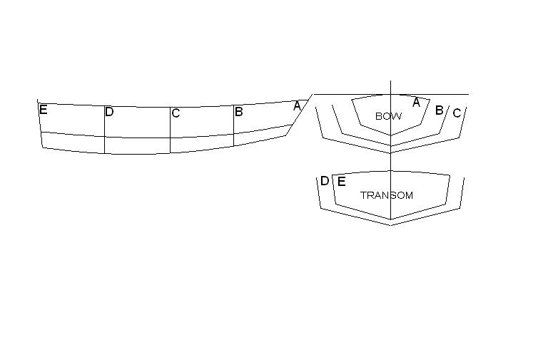
The sandcrabs were making a small dingy with marine plywood outsides. The stringers were screw strips for the longitudinal edges and corners. They had to be curved in both directions around about 3 midframes and attached to the fore and aft pieces of plywood (marine) which made the ends of the boat. The front piece angled downward toward the keel pieces, and was only about half of the width of the transom. It made the bow blunt but allowed for the water to channel down under the bow. The dingy was only about 7 feet long and 4' beam. Each side was bowed fore to aft, and the two bottom sheets were bowed along the keel boards creating a V shape for the bottom. There were frames across the keel that created a floor in the boat. It could be either rowed from mid seat, or powered by a small motor on the transom. It was fairly light overall, and easily handled by two persons which was about all it was designed to hold.
These drawings may not be fair, as drawn from memory over 40 years back. But you can likely see how the pieces would have curved in several directions.

I'd be interested in the book you were reading about the wooden steam chamber from the 1760 era.
-

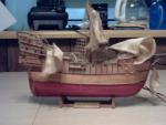
America by Walter Biles - scale 1:48 - RADIO - POF schooner from BlueJacket Shipcrafters plans
in - Build logs for subjects built 1851 - 1900
Posted · Edited by Walter Biles
Ron,
QUOTE:
After generating the hull lines, I go to 3D mode, draw out the base line, waterline, whatever you are using to determine the fore aft positions of the hull lines in the X direction. Then I rotated the hull lines 90 deg. so they run in the XZ rather than XY direction. Each "frame' is then positioned at its repective place on the reference line. you now have the 3D model of your hull. END QUOTE
You say you draw the hull lines, and I assume the station positions along it You rotated the hull so the lines display in the XZ rather than the XY direction. I am having trouble figuring out what steps to do to do what you said. Could you walk me through the steps in the program?