Supplies of the Ship Modeler's Handbook are running out. Get your copy NOW before they are gone! Click on photo to order.
×

bruce d
-
Posts
3,020 -
Joined
-
Last visited
Content Type
Profiles
Forums
Gallery
Events
Everything posted by bruce d
-
 I wish I could find a book sale like this. Well done.
 -
How about a version of the fixture for the scollsaw?
-
The advantage of using the adjustable stops is that I can make minute changes in seconds. This was useful when setting up but now it's locked. I performed a couple more tests than are shown and my guess is that each frame will take about two minutes to slot. Now I'm curious. Maybe a separate thread asking has anyone here used a dado on their Byrnes?
-
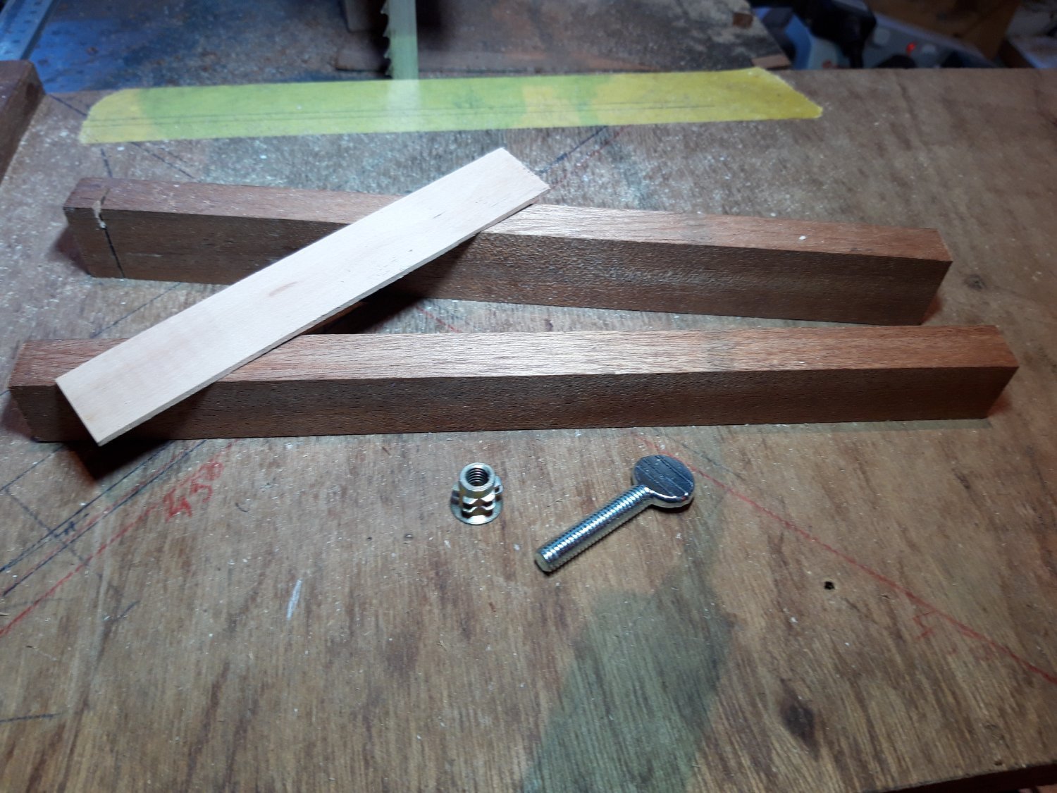
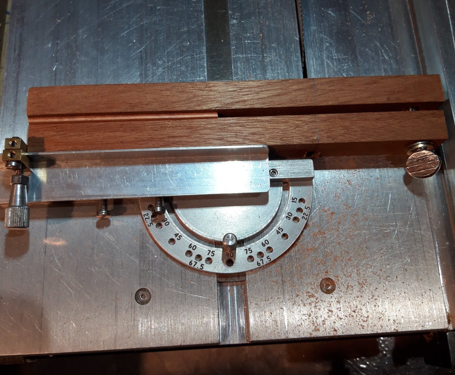
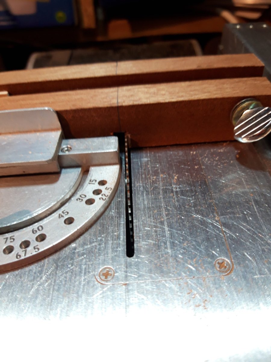
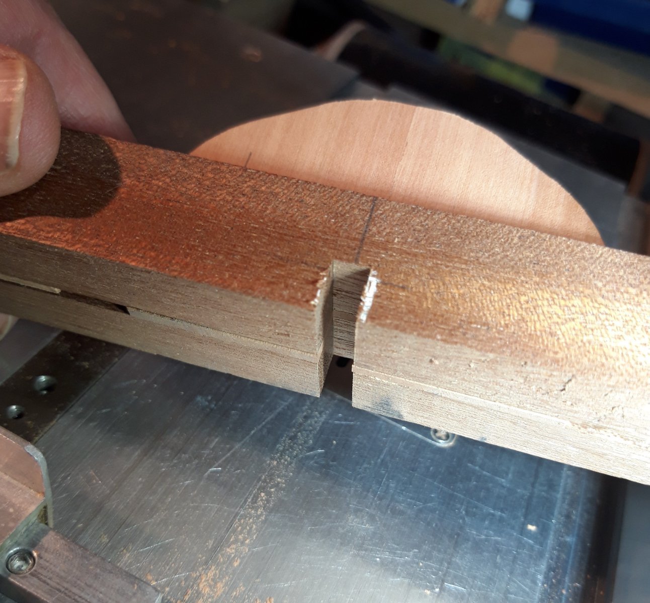
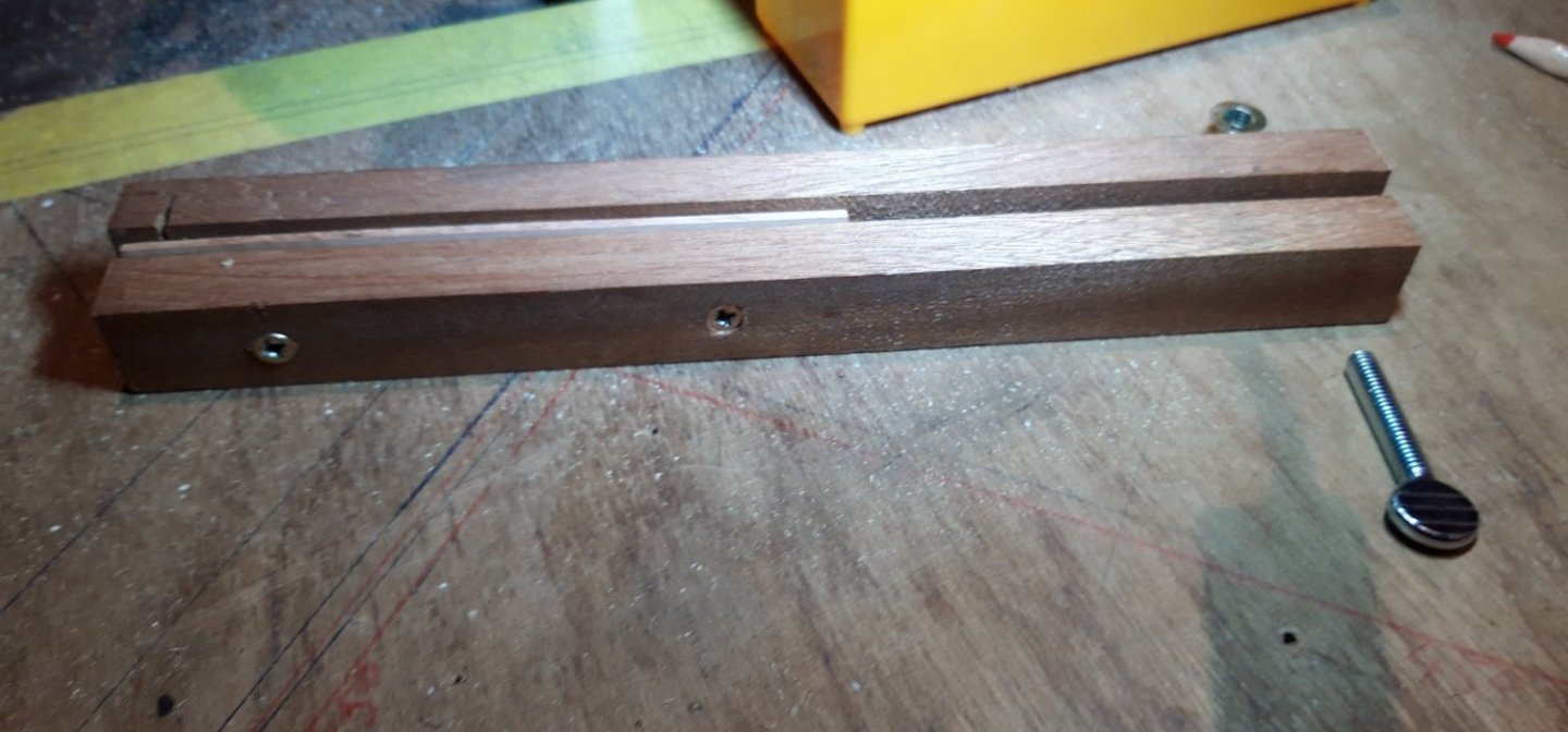
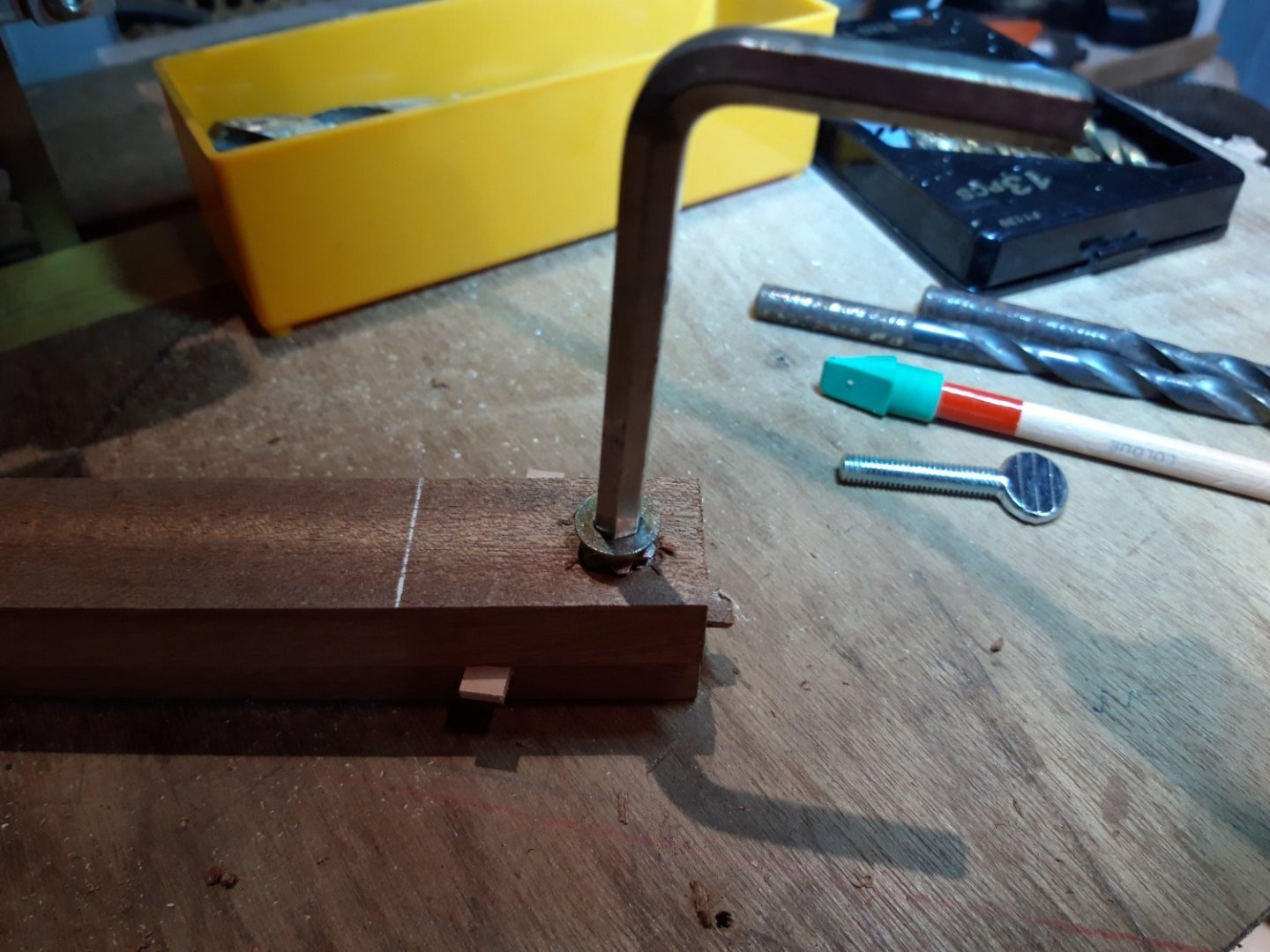
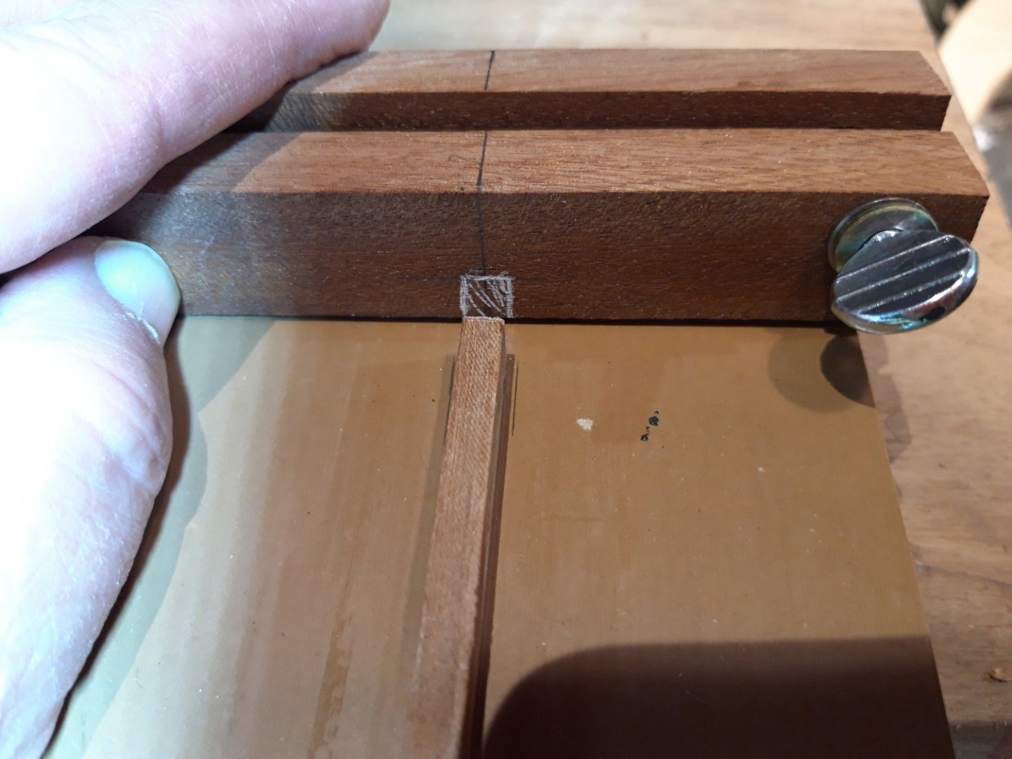
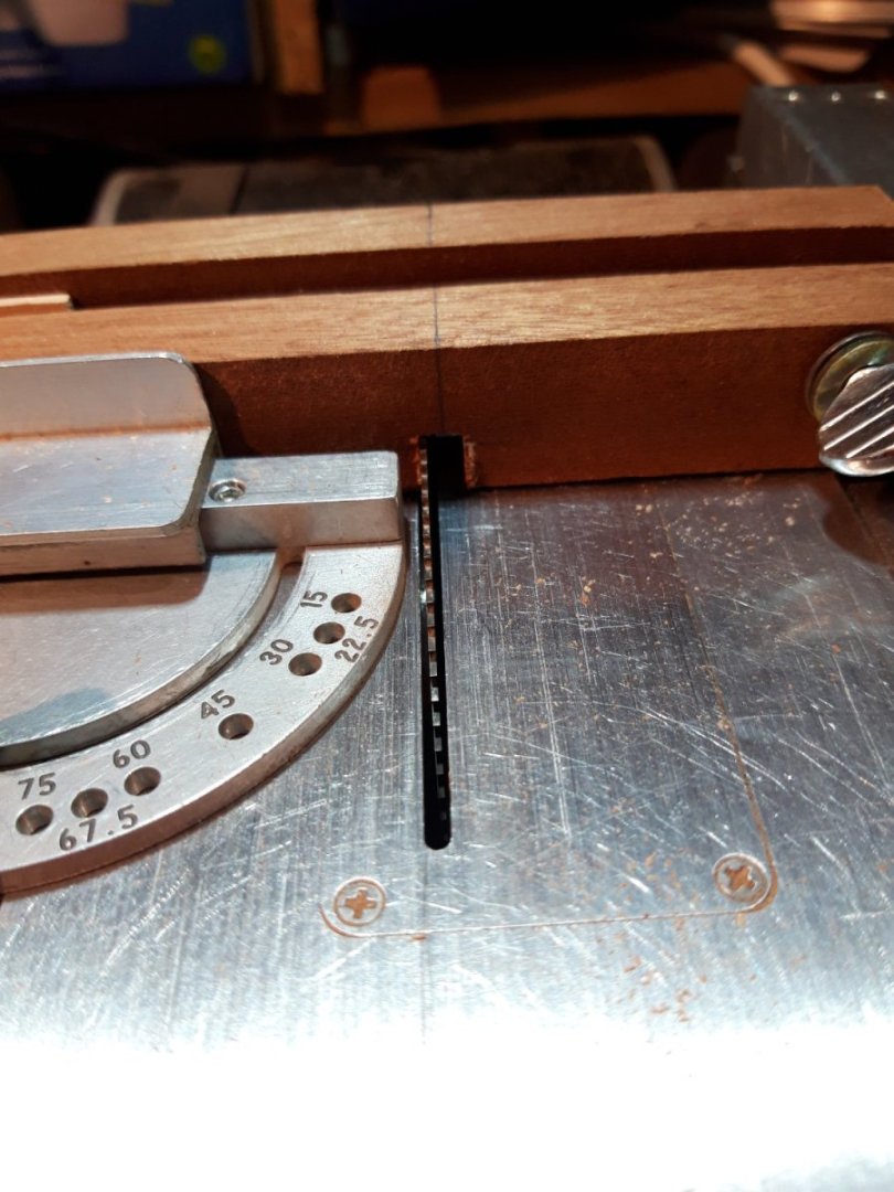
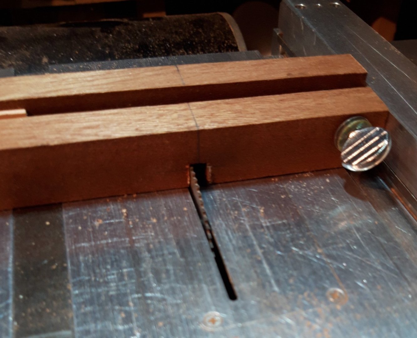
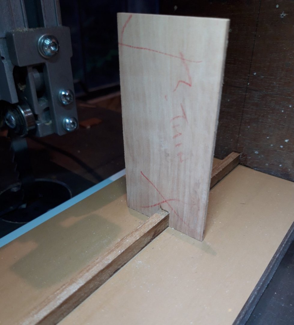
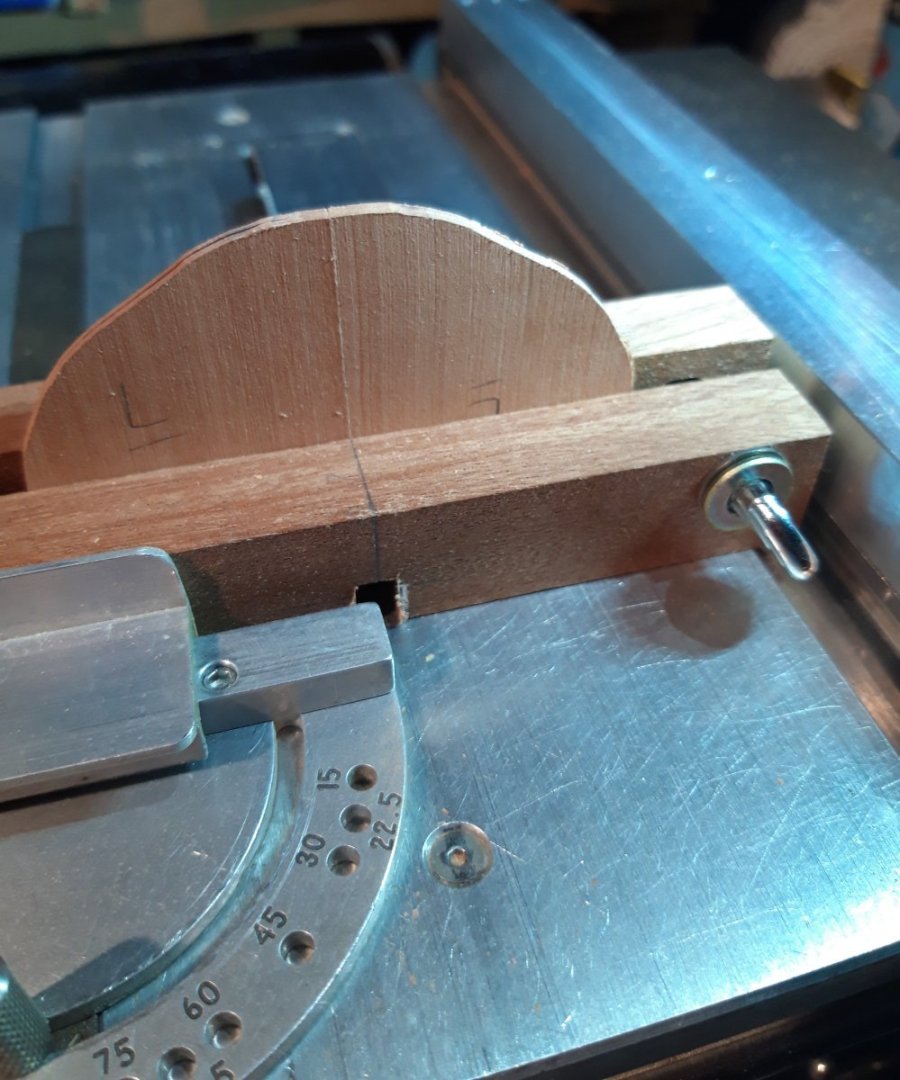
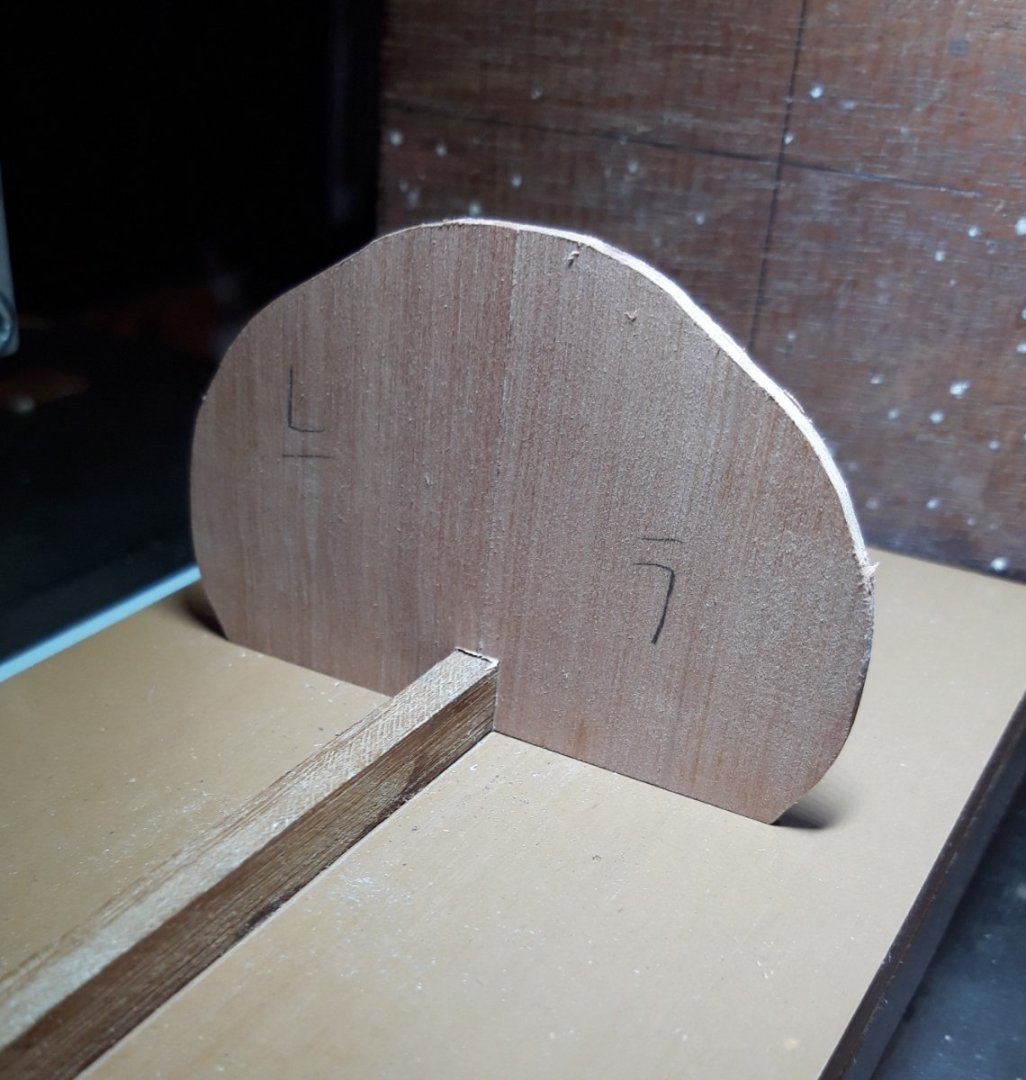
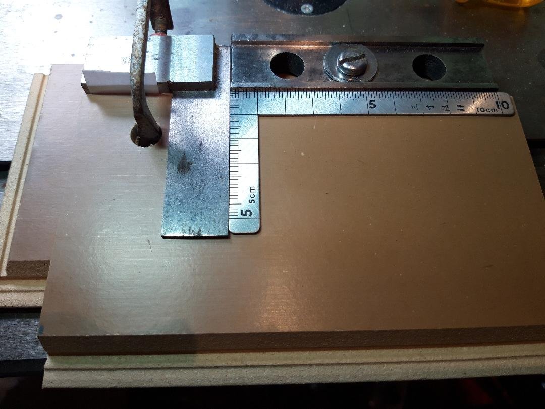
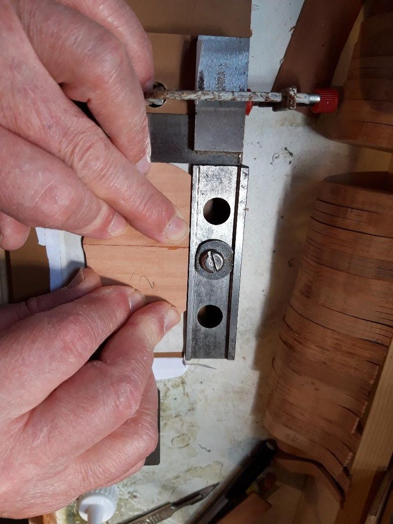
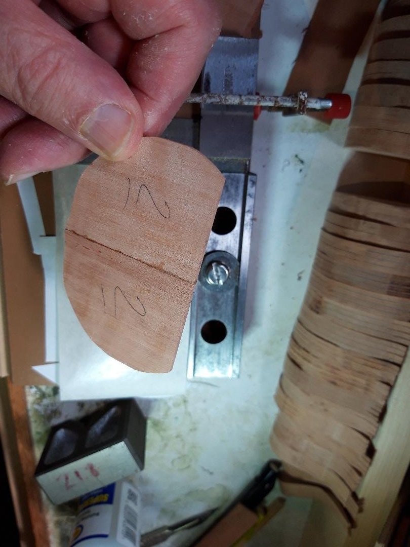
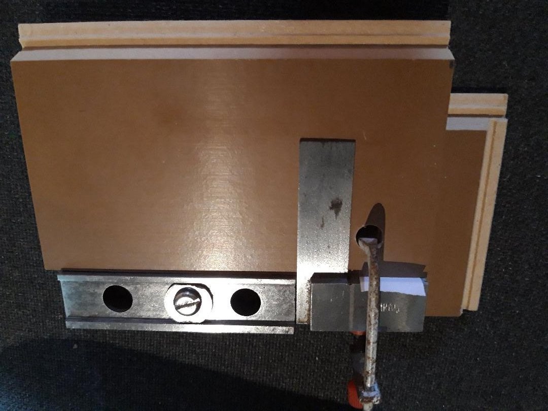
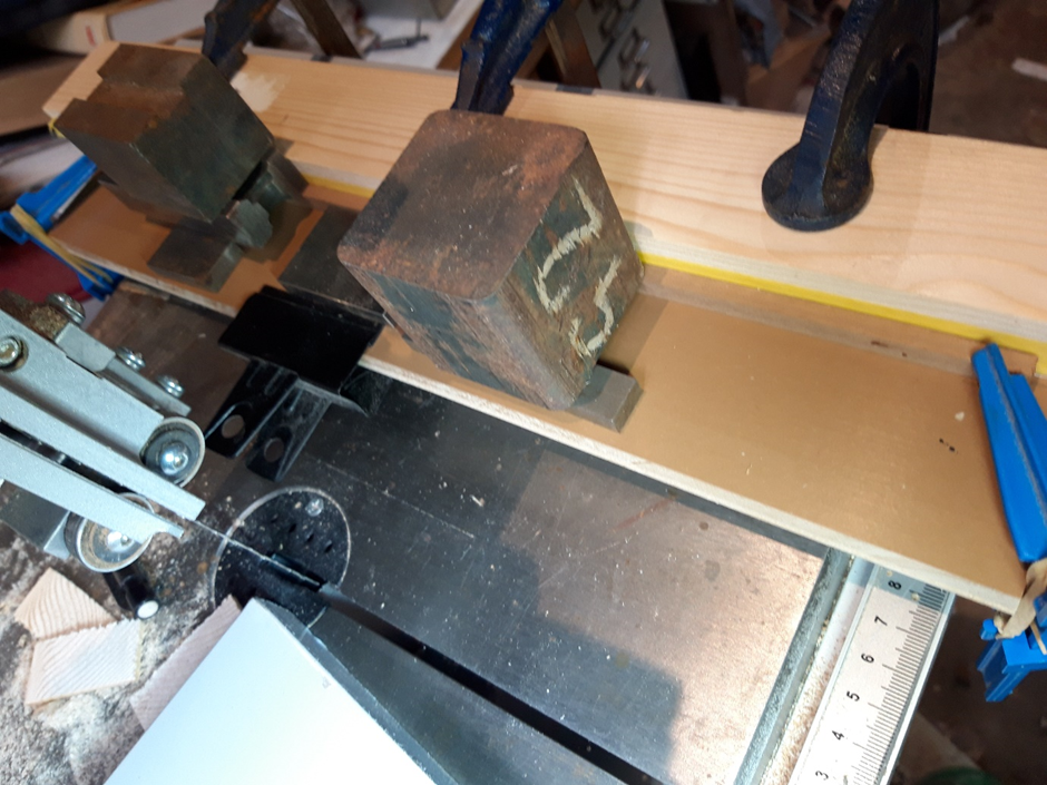
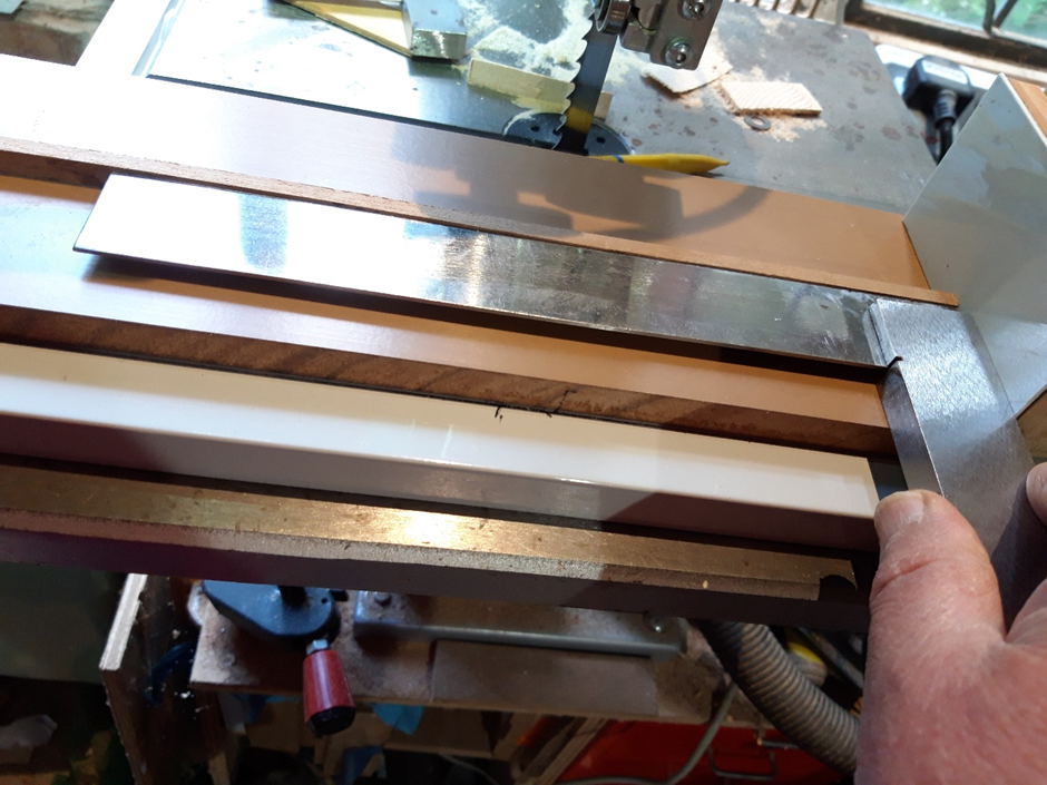
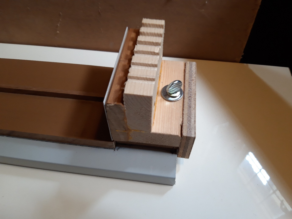
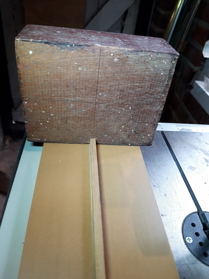
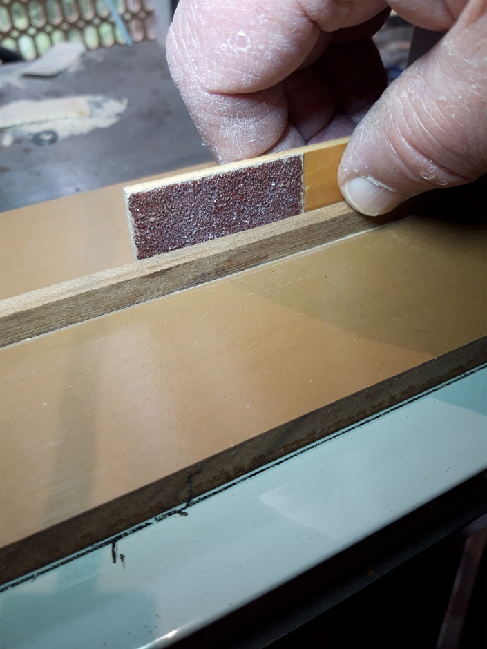
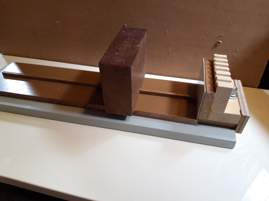
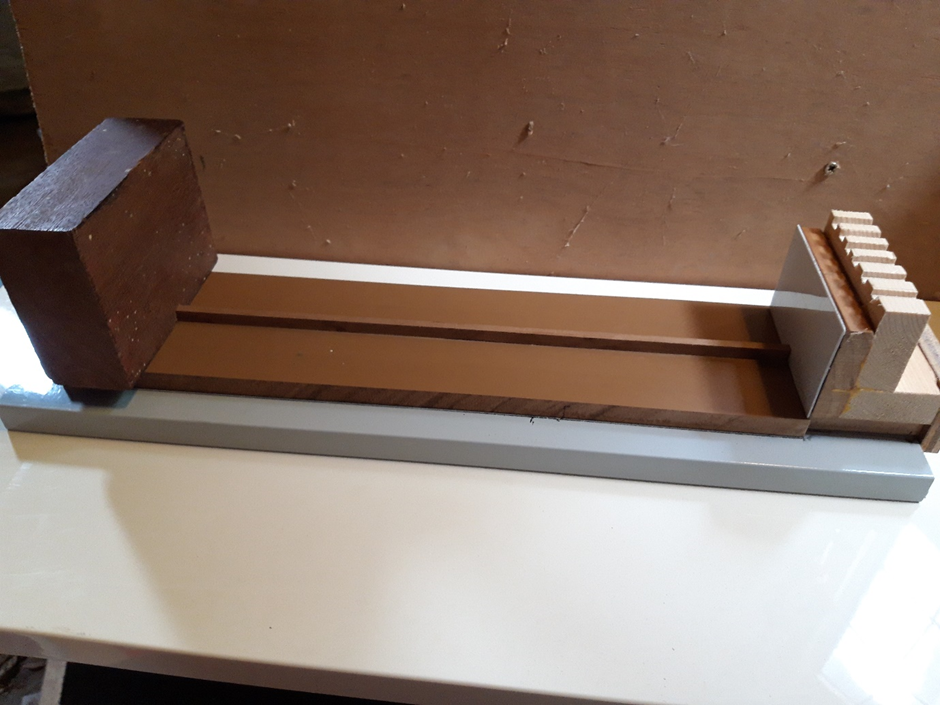
After a delay due to life-stuff, I am back in the fiddleyard. Having made the frame half-sections in pairs and fours (post #3) and then butt-jointed two together to make a complete frame (post #18), I did some quality checking. A few assemblies failed inspection and were remade from spare stock. I made about 50% more than needed when milling the Swiss pear to cover the learning curve but, so far, I have only had to remake four frames. All pieces got a very light sanding, had their identifying marks freshened up after all that handling and checked one last time. Once satisfied, it was time to cut the slot in each that would locate it accurately where it belonged on the building board. As bdgiantman2 mentions above, this stage appears demanding. The slot in each frame piece must be dead centre and a good fit on the spine running centrally on the board; if not, any slop will show up later and cause headache and grief. Getting this right started with the fussy approach taken earlier to getting each of the half-frames aligned precisely in the assembly jig. So, to business. The butt-jointed frames all have their centre-line at a perfect right angle to the straight line across the top, sort of visible in this photo: In order to put the slot consistently in the same place on all (50+) frames a jig and fixture were needed. The fixture first. It consists of two pieces of hardwood, sapele I believe, planed smooth, square and parallel; an offcut of Swiss pear as a spacer the same thickness as the frames to be held; and a thumbscrew and M6 wood insert. A couple of woodscrews finished it off. The pear was sandwiched between the two pieces of hardwood and then, after predrilling, two woodscrews pull them together. The assembly must sit flat without any rocking. I ran a plane along the bottom to make sure. In use, the threaded insert will be at the back on the right and the thumbscrew faces the operator. The gap between the pear spacer and the thumbscrew is large enough to accommodate the widest of Berwick’s frames. A line is permanently marked in this gap and a clearance slot on the bottom is scribed accurately on it. This fixture, with a frame clamped in place, will slide right and left between two fixed stops. The saw is prepared by mounting my sexy auxiliary fence with a travel stop to limit travel to the left and the standard Byrnes fence to the right. Trial and error produced a good, snug fit. Cutting the slot, with the fixture at full travel to the right: … and to the left: The finished slot: A test piece was aligned, clamped and passed back and forth over the blade. It worked well, the test piece fitted snugly on the spine: Time to try it for real. Profile ‘L’ is one of the wider profiles. Line up the centre-line, re-tighten the left and right stops and go. Viewed from below after cutting but before removing the workpiece: I am happy with the fit and, as long as I am careful lining up the joint on the profile assemblies and don’t touch the locking screws on the stops, they should all be consistent. Fifty-three to go.


-
Hello Roger and welcome to MSW from Sussex. Looks like everybody says the same thing: nice model! Regards, Bruce
-
To quote Monty Python, 'Ahhh, and ya tell 'em that today and they won't believe ya.'
-
The Boy's Own Paper, November 1881 (not too sure whether 'boys' should be given information about attaching electrical devices to noisy young siblings ...)

-
Dafi, thank you. This must be right because the contract for similar ships has different lengths for bars.
-
Thank you Gregory, Good choice, that is one of the drawings on my short list! The scantling question remains, I will look at Steel again later as suggested to see what I missed.
-
Sounds good. Which edition of Steel is that? I will look again but when I looked I thought looked it described making a capstan, not giving guidance on sizes. Looks like I can't live any longer without Allan's book!
-
Hello Allan, Thanks, I thought all answers were in that wonderful work, but alas no. Good drawings, useful text, but no tables. I trawled through my reference books thinking I had seen a simple rule but I ain't found it yet.
-
First question: How was a capstan measured? Multiple contracts relevant to my subject use the phrase '... a Main Jeer Capstand abaft on the upper Deck of 1f’ 11in’’ Diameter in the Partners'. I get it, this measurement is the effective footprint of the mechanism as it sits on the partner, but on the face of it it says nothing about the spindle, loading or diameter of the trundle head. So I'm thinking there must have been a table of proportions to give all dimensions from the one specified, as was the case for just about every other thing made in HM dockyards at the time. This is backed up by the contracts also stating the capstan shall '... in every respect to be completed as is done in His Majesty’s Yards.' Second question: What determined the length of a capstan's bars? Was it space available, ie as long as possible? Or was it a figure derived from a set of proportions as mentioned in Q1 above? I thought I had a table giving this relationship but can't find it. For context, it is for my Berwick, (74) of 1779. Thanks in advance. Bruce
-
A word of warning to all UK and continental viewers of today's Workshop. For some reason, when I googled the time difference (as always) I got TWO answers. Perhaps there is a glitch with Daylight Savings/Summertime changes but for whatever reason at least two sites advised that the UK time would be 3:30 PM while the rest correctly advised 4:30 PM. The final word on the subject of course was the ZOOM confirmation which says 4:30. NRG VIRTUAL WORKSHOP - ON-LINE RESEARCH Date & Time Jul 15, 2023 04:30 PM London BTW, I assume this problem is a glitch as I have never had contradictory answers in the past. See you there! Bruce
-
- 4
-

-
Ken, that is a great subject and I'm looking forward to seeing sawdust. Bruce
-
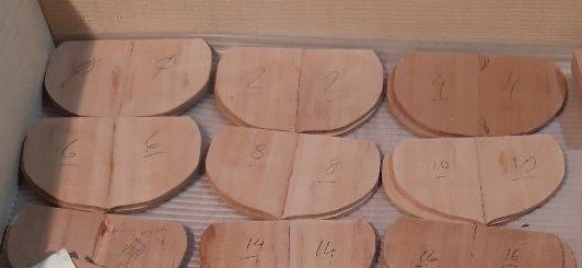
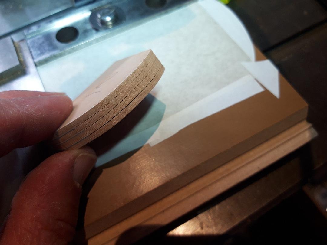
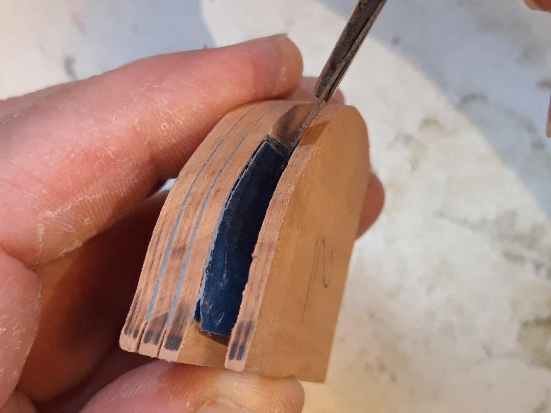
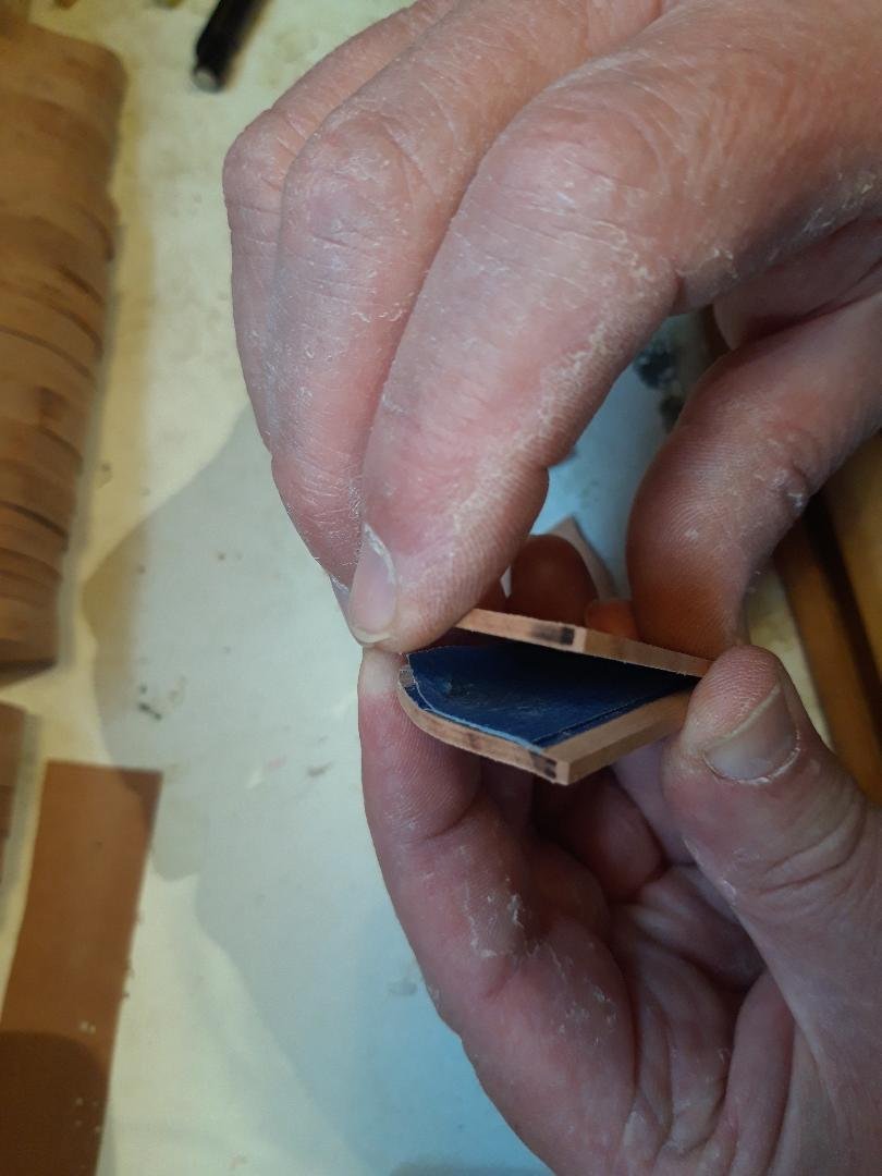
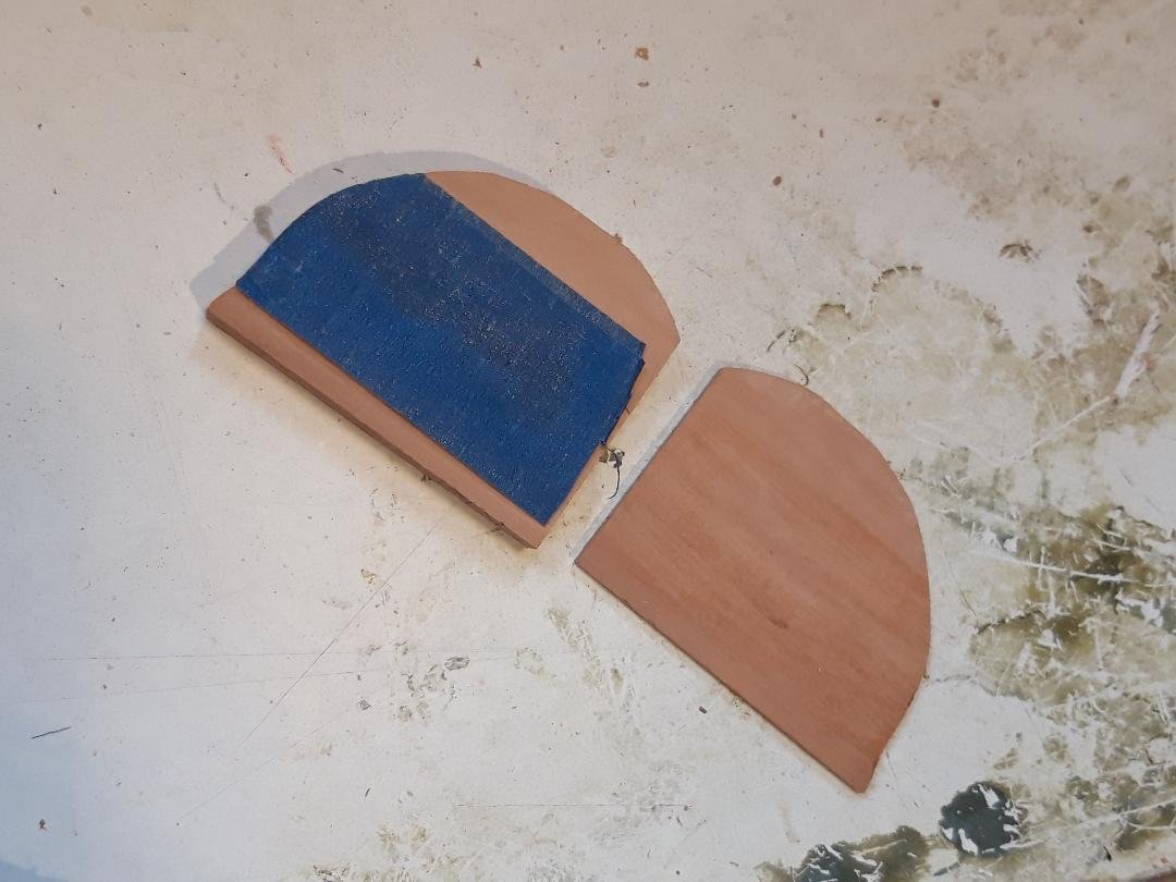
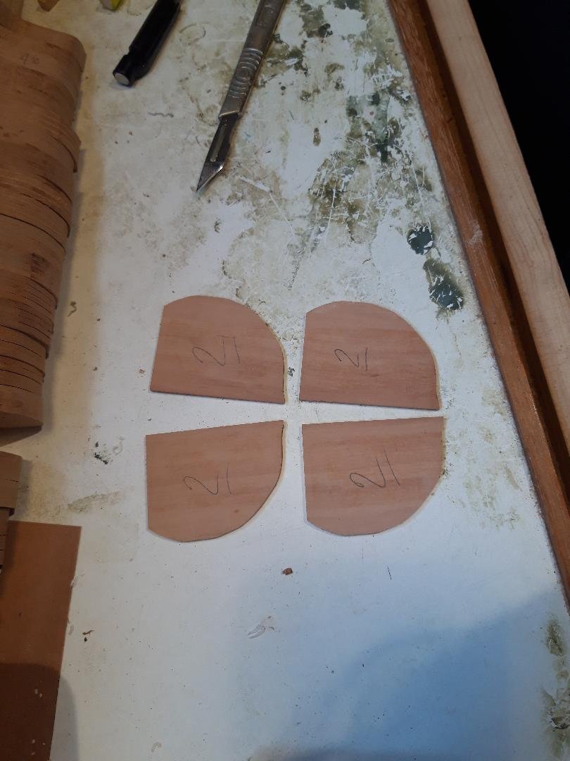
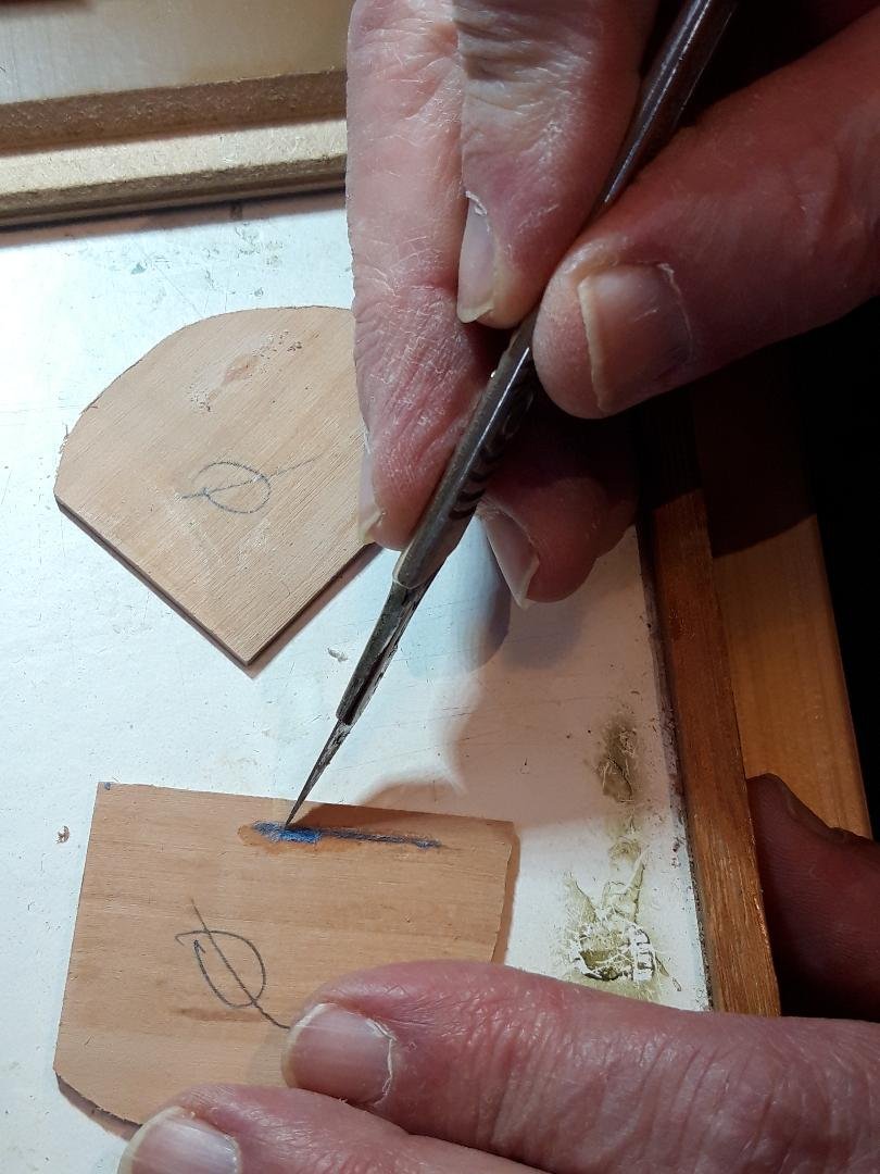
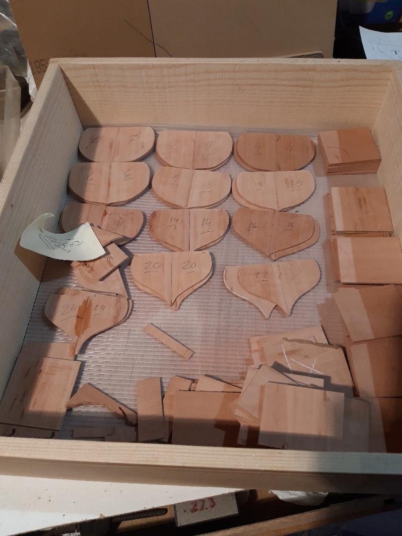
In post #12 I gave a teasing view of something that looked a little like a ship. It was made of the stacks of cut frame pieces seen at the end of post#3, just piled on edge in the right order. They remained stuck together, held by the CA & painter’s tape trick. It’s time to separate them and start some assembly. The CA/tape method worked well. Here is a stack of four frames, still perfectly aligned: Starting with a dull scalpel forced into one of the gaps, I ran it all the way around until the tape starts to give way. It opens like a clam: The painter’s tape leaves no residue. After peeling off whatever tape is left I immediately wrote the frame number on both sides of both pieces. A thorough inspection of each piece revealed a couple of rejects caused by my over-doing the CA, leading to CA on the wood. As the centres of the frames will be removed later this is not a problem but during the earlier steps there can be no high-spots when the frames are glued together face to face. Here I am dealing with a small blob and lump of tape before sanding it level. If it is too large, I would discard the piece and make a replacement. Next step is to glue two frame halves together with a butt joint. This is the jig for the assembly. It is checked for square from time to time. So, finally some assembly. The two frame halves with CA applied, pushed into position and held flat while the bond forms. There is a piece of non-stick paper between the jig face and the frames. Success. About a quarter of the frames done, notice there are a couple of duds, plus some of the thicknessed pear wood to be used in the next step. Bruce
-
Babushka-saw.mp4
-
Welcome to MSW from Sussex, hope to see some of your work. Bruce
-
Bonjour Alain and a warm welcome to MSW from the UK. I look forward to seeing your work. Bruce
-
Hello John, yes, it will coincide with a particular step in the Berwick build (soon, I hope!).
-
Hello Pat, Good points. I considered a T track system but stuck with the spine & straight edge design. I was naively expecting to make the whole building board in minutes when I decided to tackle Berwick. The written words by Reed and McNarry just brush past this part and the more I looked at it the more I saw it as a 'make or break' part of the model. We'll see if I chose right! Cheers, Bruce
-
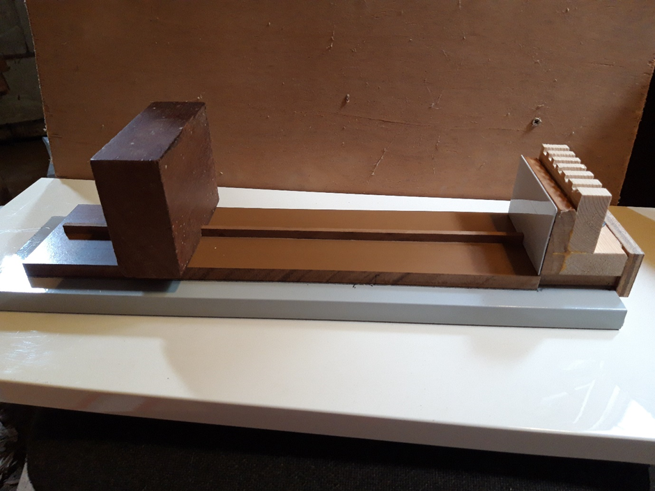
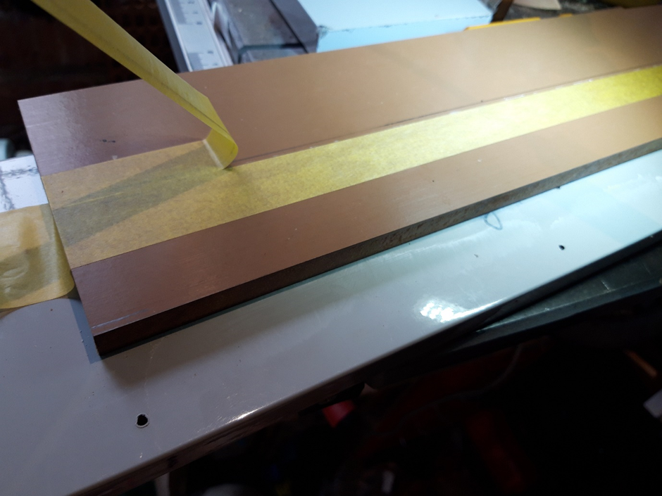
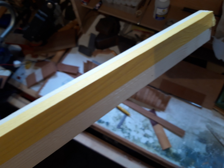
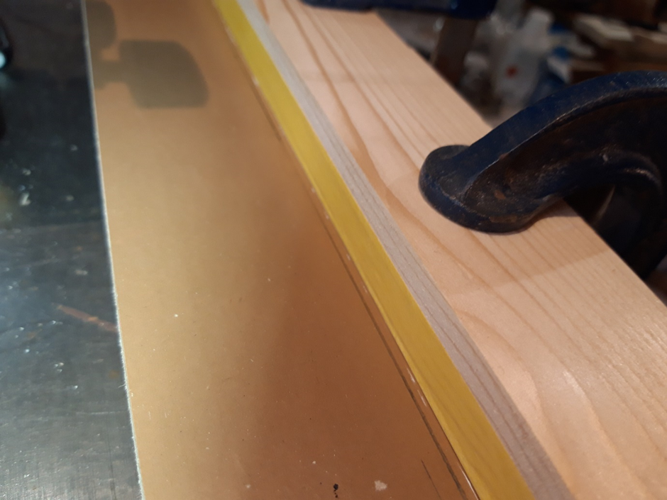
The building board. This style of construction requires a building board with distinct features. It seems there are no rules (whew!) for what the finished building board should look like as long as those features are present and the whole thing is stout enough to take a surprising amount of handling, bracing, clamping and abuse. Time will tell if/how mine can be improved. What is needed is a flat surface with a raised piece, call it a ‘spine’, running lengthwise. The spine must be straight, of uniform dimensions and tough enough to survive the building process (coming soon). The frames of the model will be aligned horizontally on this spine so it should not be vulnerable to wear. At either end there must be a flat face, square to the board, for vertical alignment. One of these faces can be fixed but the other must be able to be positioned firmly anywhere along the spine. The first board I made simply wasn’t going to be good enough. I haven’t included photos but I realised the material of the base and the spine were vulnerable to wear and knocks and I would end up in a mess. Cue some rethinking. The Mk11 board, see below, has a much greater chance of keeping things straight as the hull is assembled, dis-assembled and re-assembled as is required in this building system. To describe the beast: starting at the bottom, a dense chipboard cabinet door (the grey board) has one true straight long edge. Screwed to this is a section of laminate flooring, upside down, with truly parallel long sides. This is mounted off-set so one edge is flush with an edge of the bottom and the other creates a step giving a convenient place to mount a surface gauge. The smooth flat surface of this upper piece forms the working surface of the ‘shipyard’ and will resist wood glues. The accuracy of the spine is crucial to the alignment of the frames during construction as it is the constant reference as the various assembly/re-assembly processes unfold. A piece of cherry 5.5mm wide and 9mm high was clamped and weighted to ensure it was absolutely straight and central when epoxied to the laminate. It is a bit longer than the model and if I have thought this through correctly that extra length will be handy. Painter’s tape kept the epoxy from grabbing the batten used for a straight-edge when clamping. Checking: it worked. The ugly assembly at one end has a flat face perpendicular to the baseboard surface and the centreline. It is secured with a thumb-screw so it can be fettled back into position if it’s alignment is compromised. A series of notches along the top will allow rubber bands to be used for clamping and I will add a few pegs if needed. The ‘working’ face is 20 thou ( .5mm ) white plasticard, stuck on with double-sided tape and easily replaced if damaged. Again, wood glue won’t adhere to this material. At the other end of the board the lump of mahogany also presents a perpendicular face. It has a central groove to fit snugly over the spine and is square where it matters. The groove is long enough that it won’t twist in position. A snug fit is needed. It turns out a bit of fettling was needed to relieve tight spots: Test, test and test again. I will apply a touch of paste wax on the spine and in the groove. I will work out the best way of clamping/binding the movable piece in position once I get started. This arrangement may look clumsy and over-engineered but will remain stable on the bench. It will be possible to use a height gauge on all sides around the model as construction advances. The removable end-pieces are my ‘security blanket’ as I hurtle towards the unknown. Bruce
-
Hello Igor and welcome to MSW from the UK. Perhaps you would like to post some pictures of your models? Bruce
-
Using the link in post #19 above, this database is the alphabetical list of subjects so look at the vertical menu on the left; RATTLESNAKE will be in the set ‘No.77 – Sea’.