bruce d
-
Posts
3,034 -
Joined
-
Last visited
Content Type
Profiles
Forums
Gallery
Events
Everything posted by bruce d
-
 Some insights into lessons learned in the 1400's. The_revolutionary_cannon_of_the_15th_cen.pdf
- 1 reply
-
- 5
-

-

-
1961 Showboat Dragster by xken - 1/8th scale - scratch built
bruce d replied to xken's topic in Non-ship/categorised builds
Fantastic job, Ken, and what a great subject. I was lucky enough to see this beast run. Tommy sold it to a guy (name long forgotten) who put a Buick station wagon body on and VIOLA! - instant funny car. It was a crowd pleaser. I have some 8mm film of it somewhere, now that you have reminded me. Again, good job. 👍 -
Well done! Absolutely beautiful model, superb workmanship: you should be proud of this one. I learned a lot., thank you.
- 589 replies
-
- 2
-
-
- le gros ventre
- cargo
- (and 1 more)
-
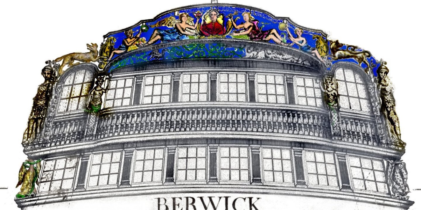
Update: I've remade a handful of frames and am plodding through the steps already described to get them into play. The next step requires all frames to be present and correct. In the meantime, I had a very pleasant visit to Royal Museums Greenwich (a.k.a. The National Maritime Museum). The only plan of Berwick showing the stern decoration and figurehead, J2632, is not available online in hi-res and I am glad to say I was allowed to view the original. The detail is superb and, I confess, more elaborate than I had imagined. There was a 'what have I done?' moment but it passed. For copyright compliance reasons I will not post the images taken directly from the original. However, I have begun a crude process of digitally separating the components and looking for clues as to what was carved and what was painted. It is based on J2632 but is modified enough to allow me to comfortably post it here. This is work-in-progress, a tool to get me closer to the finished model and will evolve. Plan A at the moment is to start on the stern decoration as soon as the re-drawing is completed, the figurehead later.
-
Danny Vadas' masting and rigging spread sheet
bruce d replied to allanyed's topic in Masting, rigging and sails
Allan, I got this message ... ... and downloaded the file. It worked fine (had to click 'enable editing' when prompted).
-
Kurt, I am sure this will be popular. Which edition is it please?
-
I wish I could find a book sale like this. Well done.
-
How about a version of the fixture for the scollsaw?
-
The advantage of using the adjustable stops is that I can make minute changes in seconds. This was useful when setting up but now it's locked. I performed a couple more tests than are shown and my guess is that each frame will take about two minutes to slot. Now I'm curious. Maybe a separate thread asking has anyone here used a dado on their Byrnes?
-
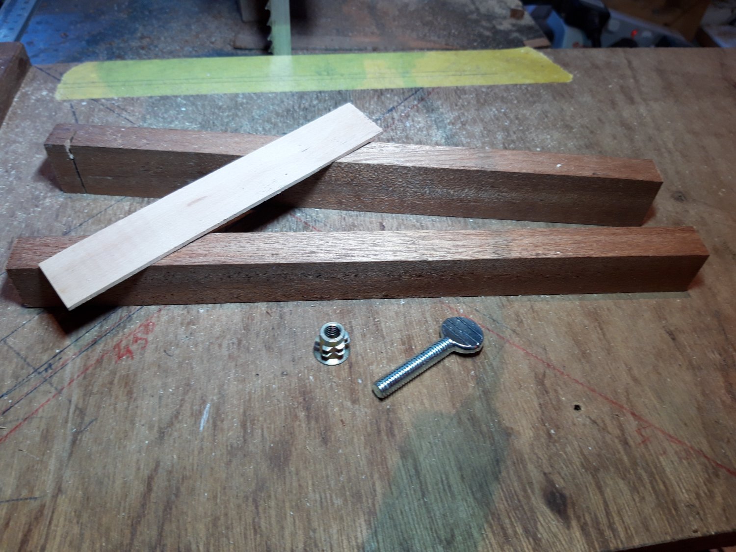
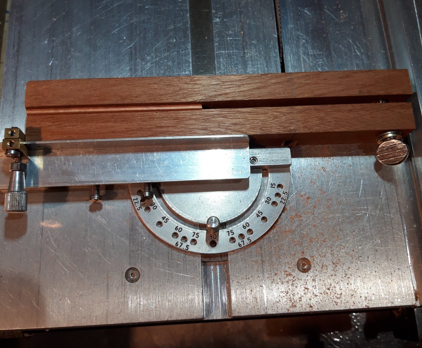
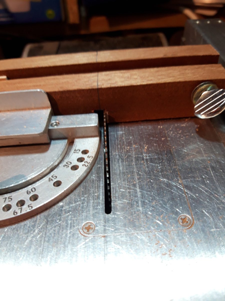
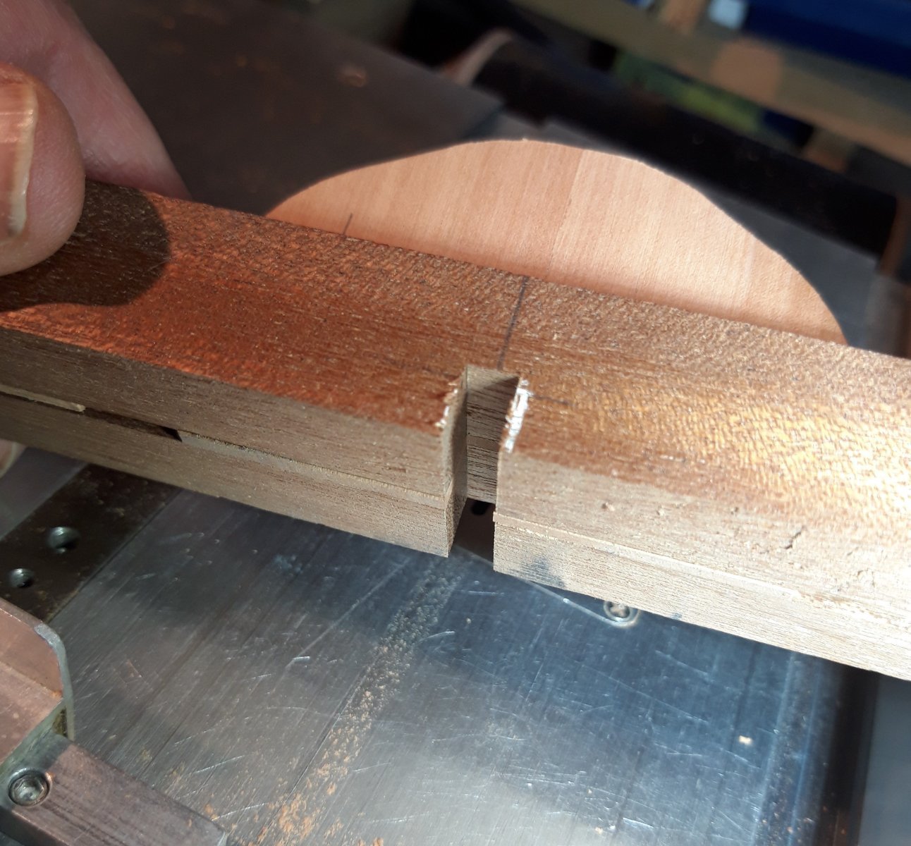
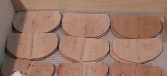
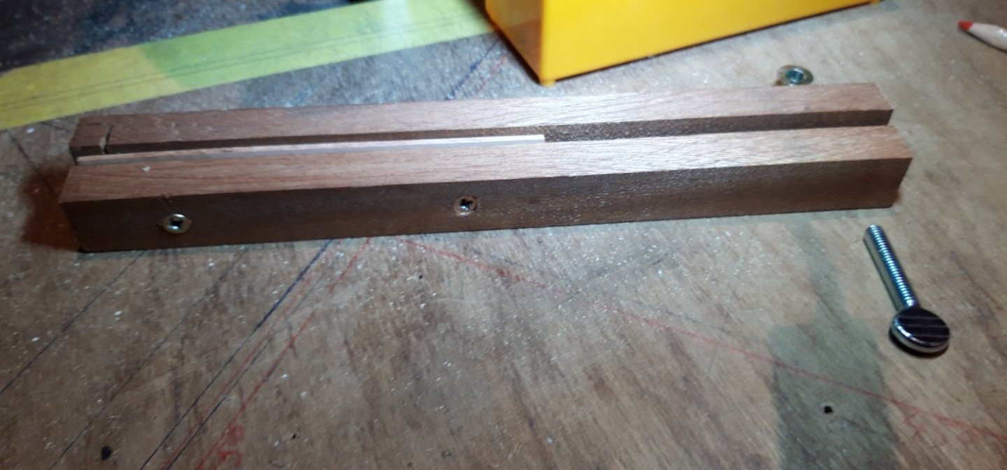
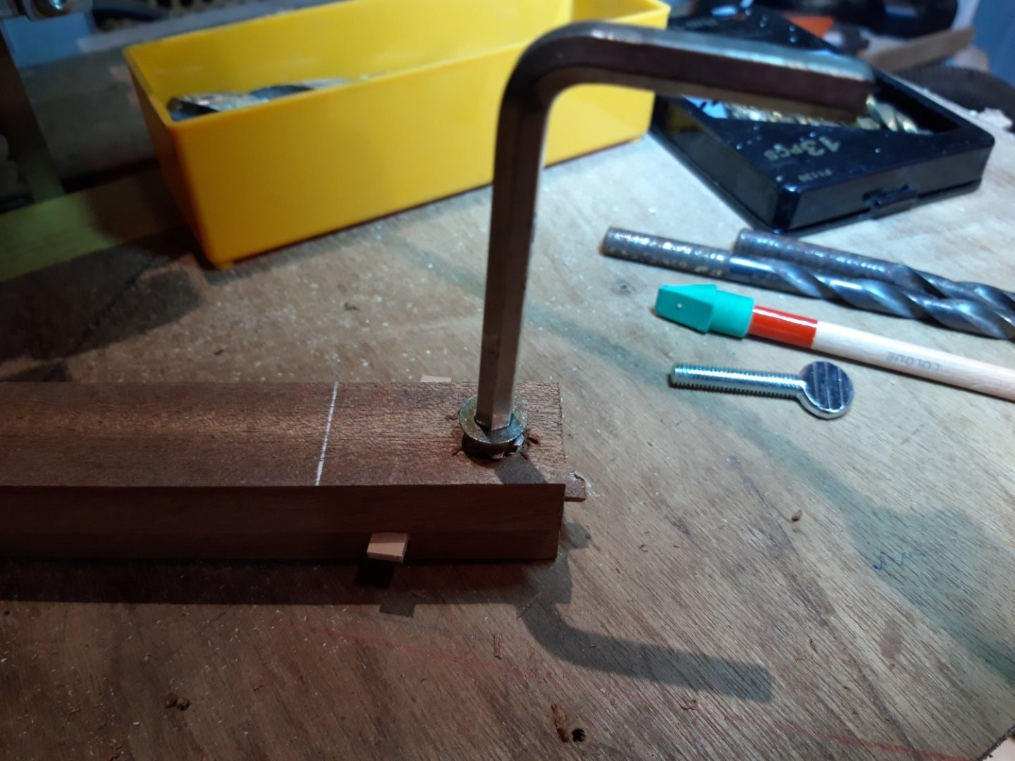
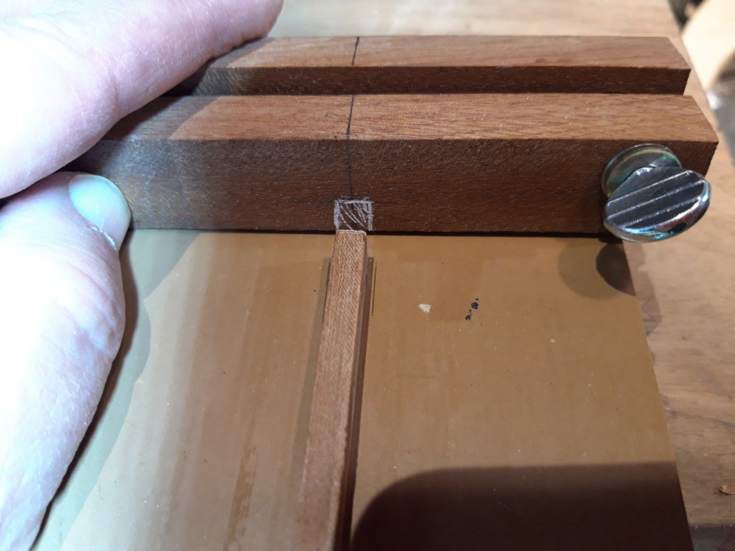
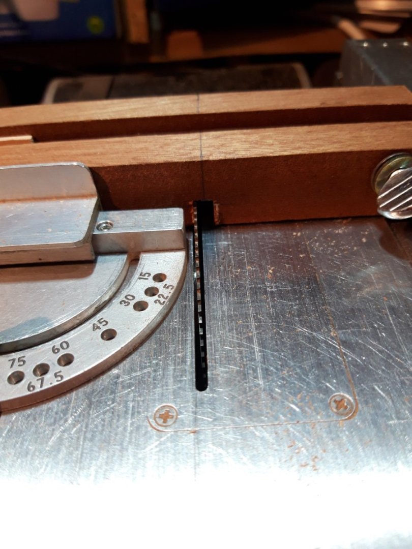
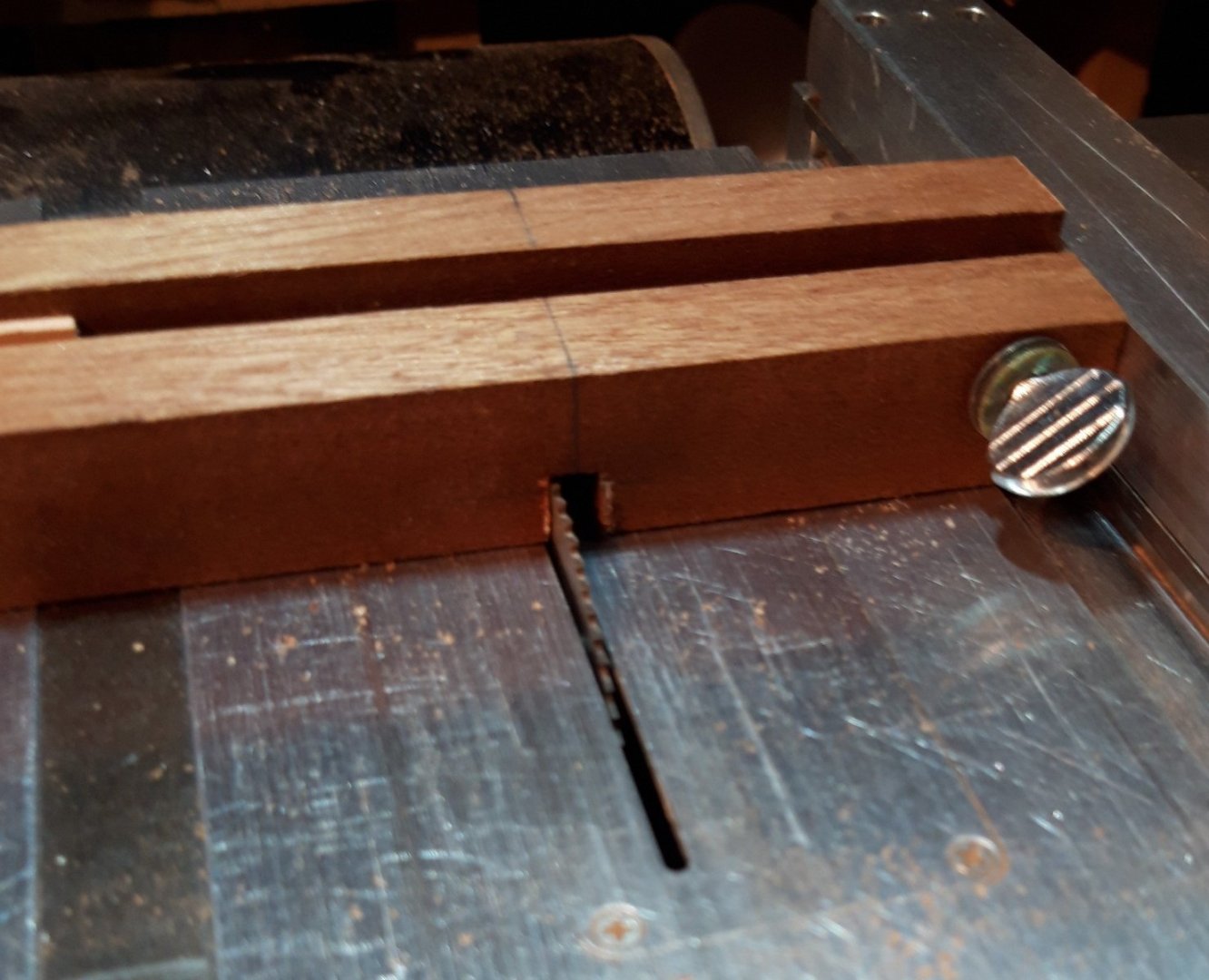
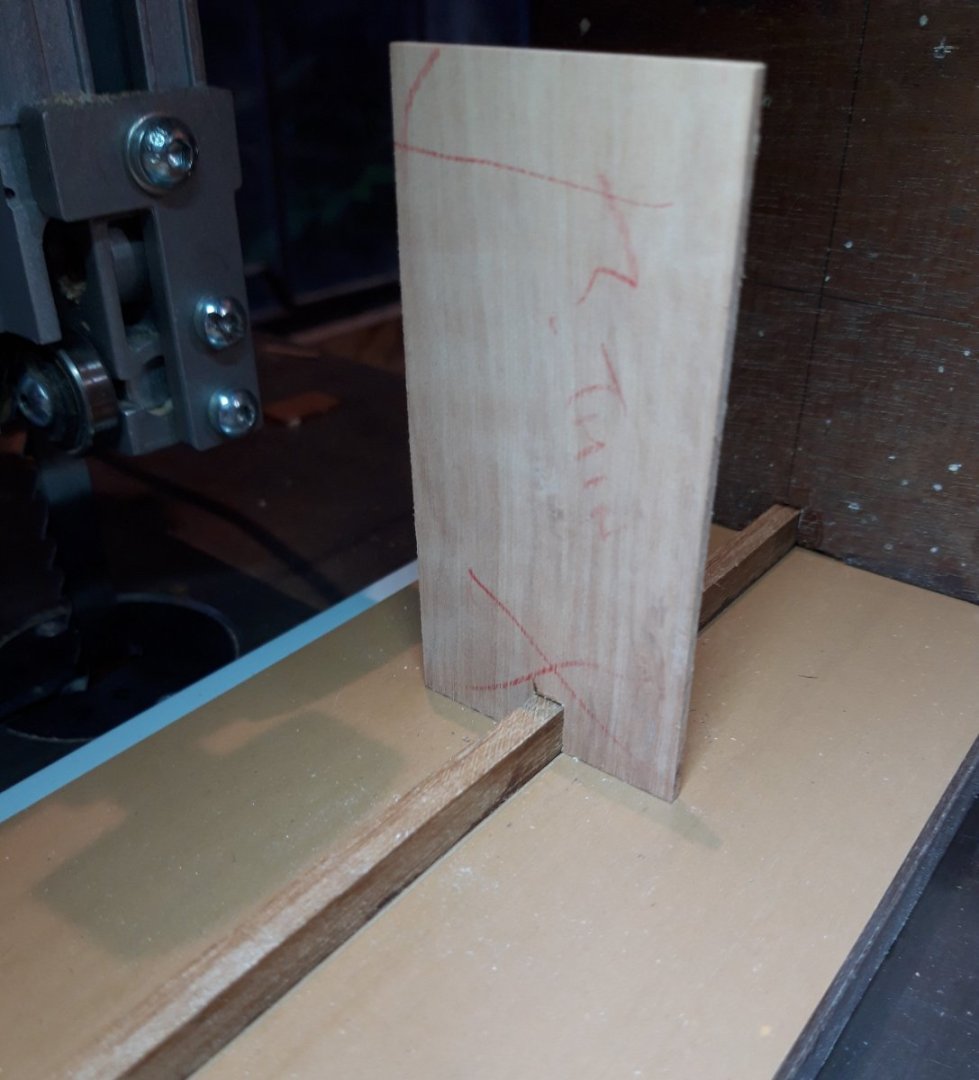
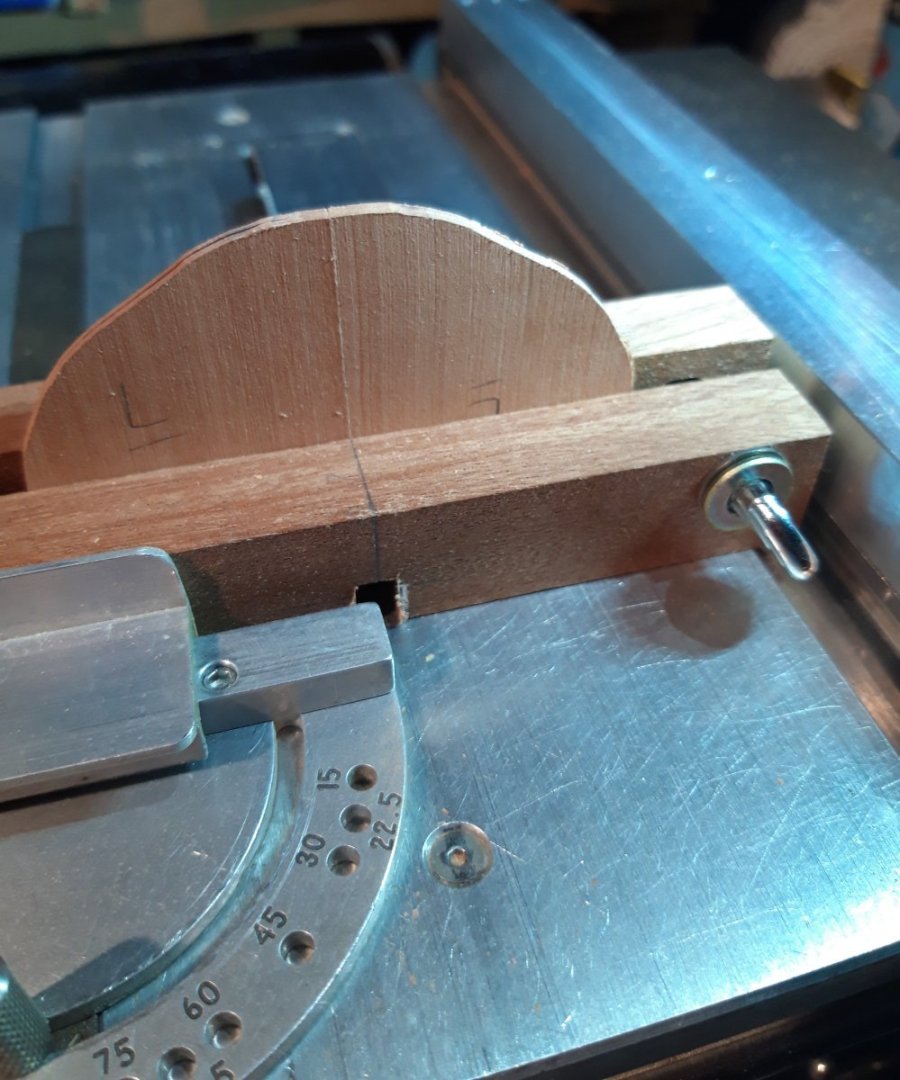
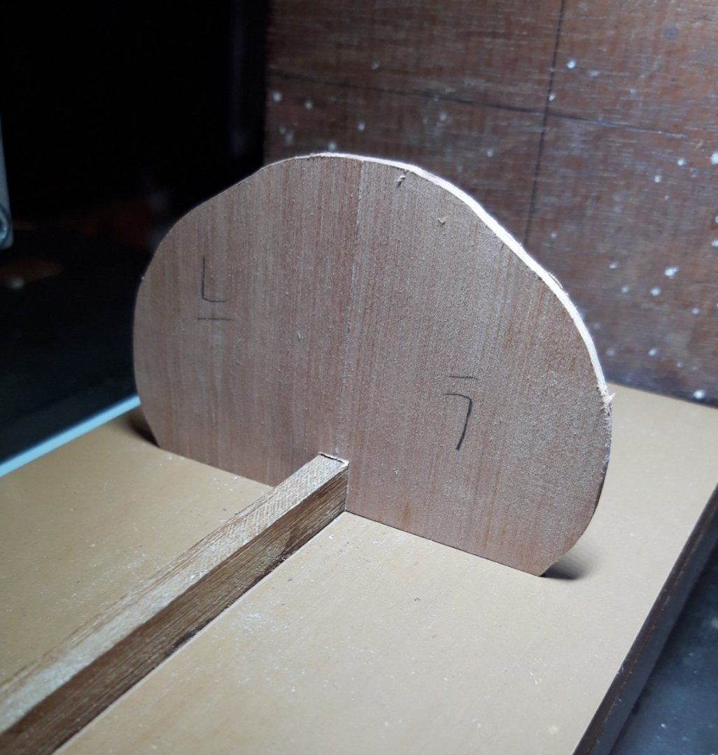
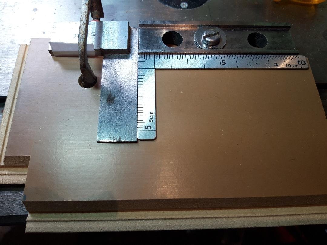
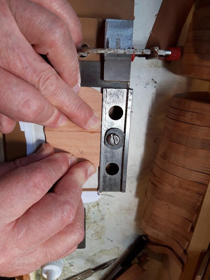
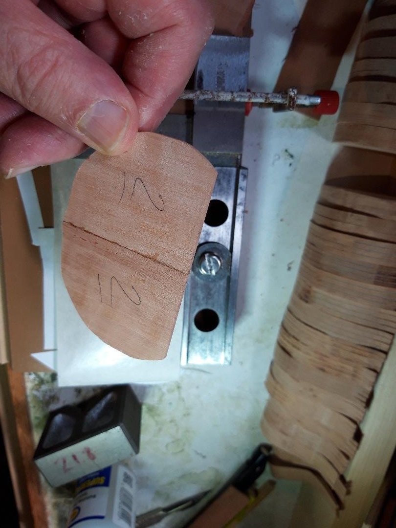
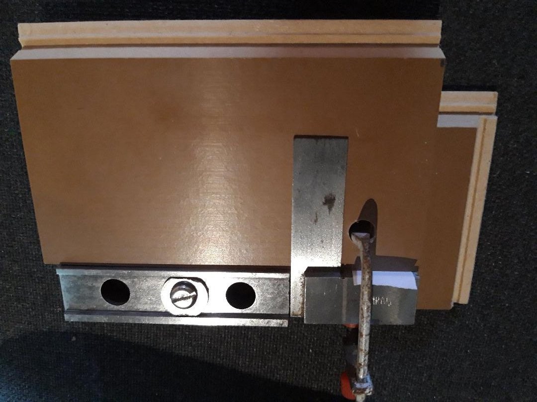
After a delay due to life-stuff, I am back in the fiddleyard. Having made the frame half-sections in pairs and fours (post #3) and then butt-jointed two together to make a complete frame (post #18), I did some quality checking. A few assemblies failed inspection and were remade from spare stock. I made about 50% more than needed when milling the Swiss pear to cover the learning curve but, so far, I have only had to remake four frames. All pieces got a very light sanding, had their identifying marks freshened up after all that handling and checked one last time. Once satisfied, it was time to cut the slot in each that would locate it accurately where it belonged on the building board. As bdgiantman2 mentions above, this stage appears demanding. The slot in each frame piece must be dead centre and a good fit on the spine running centrally on the board; if not, any slop will show up later and cause headache and grief. Getting this right started with the fussy approach taken earlier to getting each of the half-frames aligned precisely in the assembly jig. So, to business. The butt-jointed frames all have their centre-line at a perfect right angle to the straight line across the top, sort of visible in this photo: In order to put the slot consistently in the same place on all (50+) frames a jig and fixture were needed. The fixture first. It consists of two pieces of hardwood, sapele I believe, planed smooth, square and parallel; an offcut of Swiss pear as a spacer the same thickness as the frames to be held; and a thumbscrew and M6 wood insert. A couple of woodscrews finished it off. The pear was sandwiched between the two pieces of hardwood and then, after predrilling, two woodscrews pull them together. The assembly must sit flat without any rocking. I ran a plane along the bottom to make sure. In use, the threaded insert will be at the back on the right and the thumbscrew faces the operator. The gap between the pear spacer and the thumbscrew is large enough to accommodate the widest of Berwick’s frames. A line is permanently marked in this gap and a clearance slot on the bottom is scribed accurately on it. This fixture, with a frame clamped in place, will slide right and left between two fixed stops. The saw is prepared by mounting my sexy auxiliary fence with a travel stop to limit travel to the left and the standard Byrnes fence to the right. Trial and error produced a good, snug fit. Cutting the slot, with the fixture at full travel to the right: … and to the left: The finished slot: A test piece was aligned, clamped and passed back and forth over the blade. It worked well, the test piece fitted snugly on the spine: Time to try it for real. Profile ‘L’ is one of the wider profiles. Line up the centre-line, re-tighten the left and right stops and go. Viewed from below after cutting but before removing the workpiece: I am happy with the fit and, as long as I am careful lining up the joint on the profile assemblies and don’t touch the locking screws on the stops, they should all be consistent. Fifty-three to go.


-
Hello Roger and welcome to MSW from Sussex. Looks like everybody says the same thing: nice model! Regards, Bruce
-
To quote Monty Python, 'Ahhh, and ya tell 'em that today and they won't believe ya.'
-
The Boy's Own Paper, November 1881 (not too sure whether 'boys' should be given information about attaching electrical devices to noisy young siblings ...)

-
Dafi, thank you. This must be right because the contract for similar ships has different lengths for bars.
-
Thank you Gregory, Good choice, that is one of the drawings on my short list! The scantling question remains, I will look at Steel again later as suggested to see what I missed.
-
Sounds good. Which edition of Steel is that? I will look again but when I looked I thought looked it described making a capstan, not giving guidance on sizes. Looks like I can't live any longer without Allan's book!
-
Hello Allan, Thanks, I thought all answers were in that wonderful work, but alas no. Good drawings, useful text, but no tables. I trawled through my reference books thinking I had seen a simple rule but I ain't found it yet.
-
First question: How was a capstan measured? Multiple contracts relevant to my subject use the phrase '... a Main Jeer Capstand abaft on the upper Deck of 1f’ 11in’’ Diameter in the Partners'. I get it, this measurement is the effective footprint of the mechanism as it sits on the partner, but on the face of it it says nothing about the spindle, loading or diameter of the trundle head. So I'm thinking there must have been a table of proportions to give all dimensions from the one specified, as was the case for just about every other thing made in HM dockyards at the time. This is backed up by the contracts also stating the capstan shall '... in every respect to be completed as is done in His Majesty’s Yards.' Second question: What determined the length of a capstan's bars? Was it space available, ie as long as possible? Or was it a figure derived from a set of proportions as mentioned in Q1 above? I thought I had a table giving this relationship but can't find it. For context, it is for my Berwick, (74) of 1779. Thanks in advance. Bruce
-
A word of warning to all UK and continental viewers of today's Workshop. For some reason, when I googled the time difference (as always) I got TWO answers. Perhaps there is a glitch with Daylight Savings/Summertime changes but for whatever reason at least two sites advised that the UK time would be 3:30 PM while the rest correctly advised 4:30 PM. The final word on the subject of course was the ZOOM confirmation which says 4:30. NRG VIRTUAL WORKSHOP - ON-LINE RESEARCH Date & Time Jul 15, 2023 04:30 PM London BTW, I assume this problem is a glitch as I have never had contradictory answers in the past. See you there! Bruce
-
- 4
-
-
Ken, that is a great subject and I'm looking forward to seeing sawdust. Bruce
-
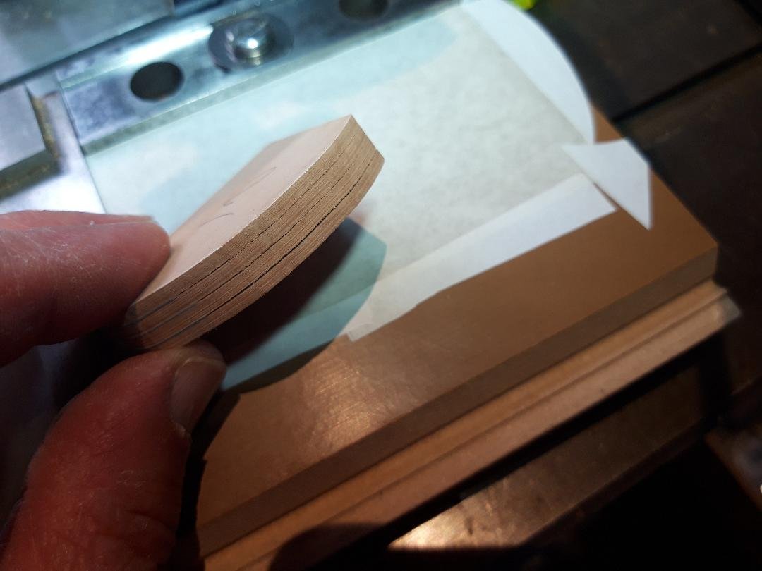
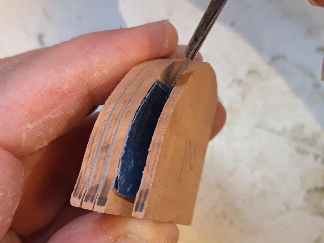
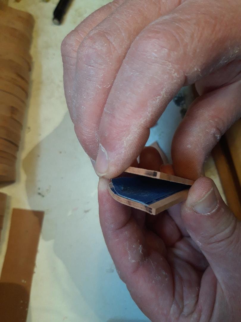
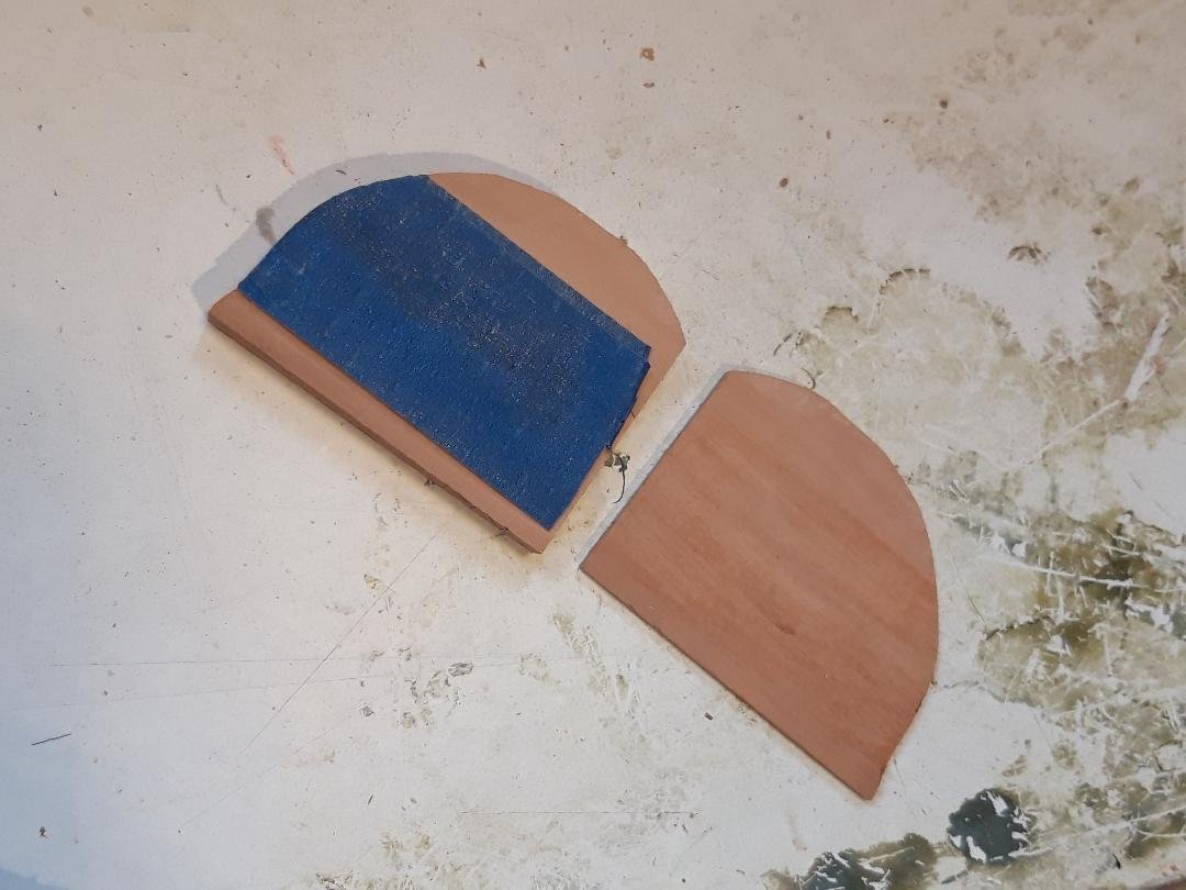
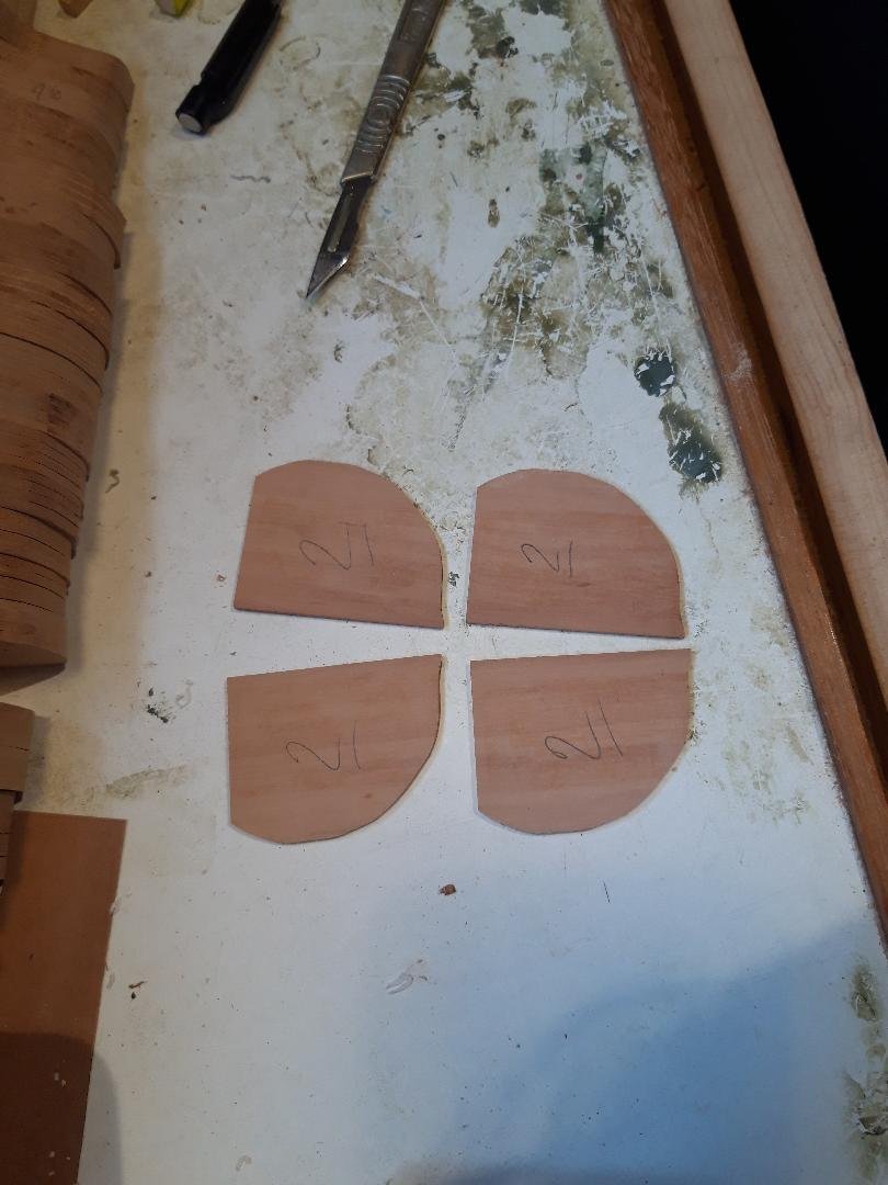
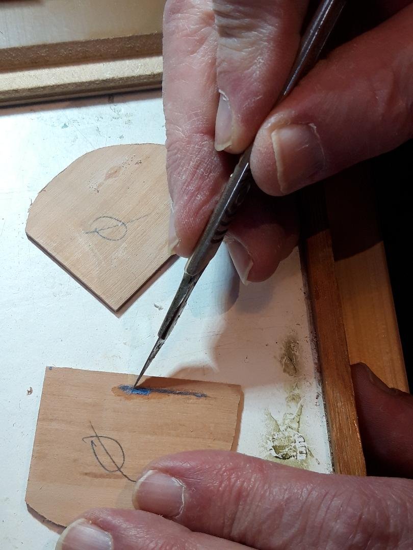
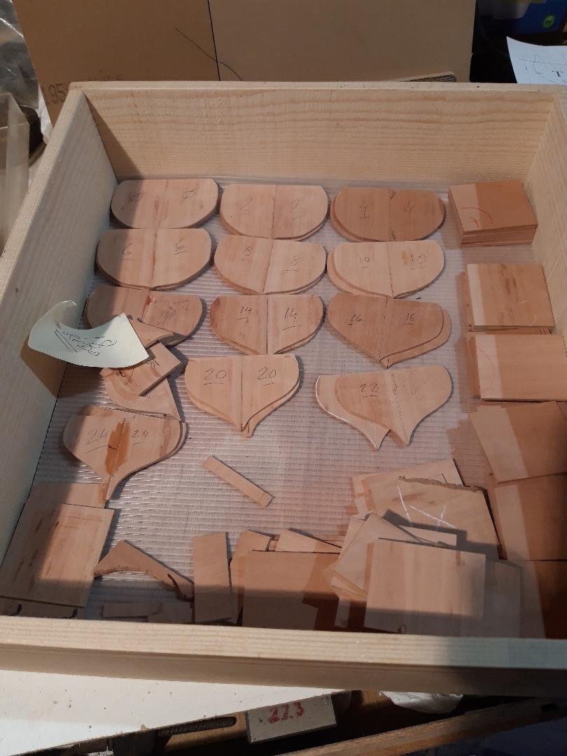
In post #12 I gave a teasing view of something that looked a little like a ship. It was made of the stacks of cut frame pieces seen at the end of post#3, just piled on edge in the right order. They remained stuck together, held by the CA & painter’s tape trick. It’s time to separate them and start some assembly. The CA/tape method worked well. Here is a stack of four frames, still perfectly aligned: Starting with a dull scalpel forced into one of the gaps, I ran it all the way around until the tape starts to give way. It opens like a clam: The painter’s tape leaves no residue. After peeling off whatever tape is left I immediately wrote the frame number on both sides of both pieces. A thorough inspection of each piece revealed a couple of rejects caused by my over-doing the CA, leading to CA on the wood. As the centres of the frames will be removed later this is not a problem but during the earlier steps there can be no high-spots when the frames are glued together face to face. Here I am dealing with a small blob and lump of tape before sanding it level. If it is too large, I would discard the piece and make a replacement. Next step is to glue two frame halves together with a butt joint. This is the jig for the assembly. It is checked for square from time to time. So, finally some assembly. The two frame halves with CA applied, pushed into position and held flat while the bond forms. There is a piece of non-stick paper between the jig face and the frames. Success. About a quarter of the frames done, notice there are a couple of duds, plus some of the thicknessed pear wood to be used in the next step. Bruce
-
Babushka-saw.mp4
-
Welcome to MSW from Sussex, hope to see some of your work. Bruce