bruce d
-
Posts
3,034 -
Joined
-
Last visited
Content Type
Profiles
Forums
Gallery
Events
Everything posted by bruce d
-
Hello Robert and welcome to MSW from Sussex.
-
 If I recall correctly, a caption in a contemporary magazine described the car as 'Corvette silver'.
 -
Now that really takes me back. The kit was a great source for parts and served as an organ donor for a couple of my altereds and rails. Good kit, mind if I watch?
-
Welcome to MSW from the UK.
-
Welcome to MSW from the UK.
-
Hello Jölle and a warm welcome from the UK.
-
I'm wondering if the mystery items are for a specific task. I have read of a carpenter preparing a ship's boats used for anchor work or artillery transport and assumed it was fitting the needed items rather than making any permanent modifications. Having fruitlessly spent some time trying to find details of any of these modifications I concluded the shipwrights and carpenters were directed in some way that was not recorded. The one area where I know very specific arrangements were made was in preparing boats for launching Congreve rockets but alas, they do not appear to have survived. FWIW, I will dig out a drawing I found showing the proposed method of outfitting a boat of that period with a slide for mounting an artillery piece. If memory serves it used rollers ... who knows if it fits but we'll see? HTH, Bruce
-
Rolltop Desk by kgstakes - 1/4 scale
bruce d replied to kgstakes's topic in Completed non-ship models
Very cool, Kurt. I can instantly think of a dozen questions about this desk so, yes please, I would like to see a log and get a look at your processes. Bruce- 1 reply
-
- 4
-

-
Kinsale played a big role in the 17th and 18th centuries and built at least one RN frigate, HMS Kinsale. Kinsale Dockyard - Wikipedia According to this page HMS Kinsale was the only ship built there for the RN: List of frigate classes of the Royal Navy - Wikipedia Nothing I have found in The National Archives catalogue contradicts this. There was a lot of activity but it was almost exclusively maintenance and repairs. Ireland produced a lot of shipwrights for HM shipyards but I speculate that this was due to a healthy trade in merchant craft. HTH, Bruce
-
Thanks Druxey, you bet. I am not made of the right stuff to attempt doing it in one piece.
-
It looks like Apollo has landed on his feet. He's a cutie!
- 443 replies
-
- 4
-
-
- Indefatigable
- Vanguard Models
- (and 1 more)
-
Pretty impressive, Chris. You are slowly eroding my resistance to card models ... oh dear, another rabbit hole .
-
Update: I'm chipping away at the frames as time allows, will post photos when I reach a natural break. Also, work has begun on the fixture to hold work in progress for stern decorations. The Society of Model Shipwrights is linked with MSW as a chapter club. A talk on building Berwick is now on their channel: Bruce
-
18-Pounder Pivot Gun
bruce d replied to AndyHall's topic in CAD and 3D Modelling/Drafting Plans with Software
These may be of use: Rijksmuseum Rijksmuseum HTH, Bruce -
FM, good advice (as usual) from Allan, and another book by Philip Reed is close to your stated needs: PERIOD SHIP MODELMAKING An Illustrated Masterclass It's on Ebay, AbeBooks and other places as well. In iit he walks us through building Prince de Neufchatel in 1/192 scale. McNarry and his wife were superb modelmakers and won quite a few pots at early Model Engineer Exhibitions in London. HTH, Bruce
-
Size of a printer needed
bruce d replied to Frank Burroughs's topic in Modeling tools and Workshop Equipment
What Allan said, plus check the lines with a straightedge and measure the diagonals (corner to corner) for skew. -
Hello Paul and welcome to MSW from the UK.
-
Ships at Trafalgar - what kits are available?
bruce d replied to bruce d's topic in Wood ship model kits
Update: AL have just announced a whole new Santisma Trinidad: Also, JoTika are promising a 74 with an interesting history. My bet is it will be HMS Defiance, a Trafalgar veteran, but we will have to wait and see. -
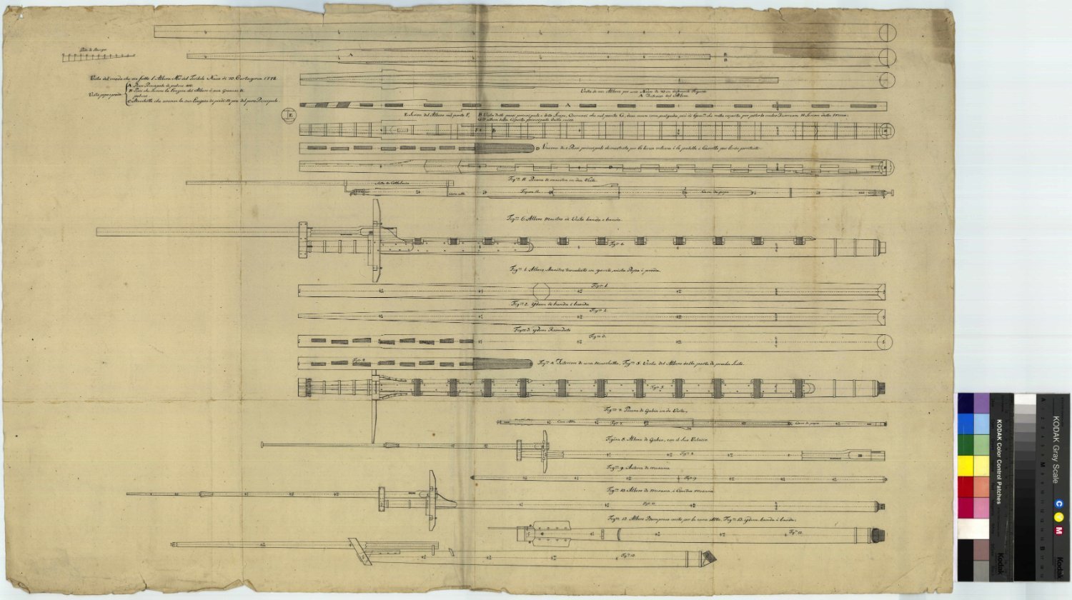
Construction of Masts for 18th Century 'Ships of the Line'
bruce d replied to tmj's topic in Nautical/Naval History
This is from NMM/RMG Collections, ZAZ6764.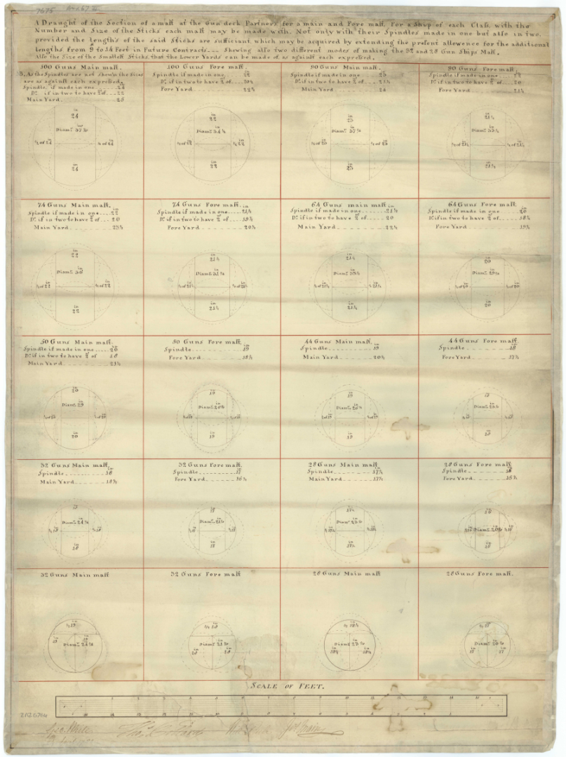
-
From Falconer, 1780: No mention of chains. HTH, Bruce

-
Fascinating. My only potential contribution is to look at the word FULMINANT when translated into English. The modern translations all steer us to 'angry', 'furious' or 'quick like lightning' but the older translations included 'splendid'. The magnificent drawings have a theme of bundled lightning and flaming spheres. They follow military decorations and emblems of grenadiers of the period so closely that it cannot be a co-incidence. These decorations would have suited a bomb vessel.
-
Fix uneven paint area
bruce d replied to DMM's topic in Painting, finishing and weathering products and techniques
Bummer. It would help a lot to know a some more such as what paint, was it brushed or sprayed? It looks like a plastic model so hopefully it will stand a bit of handling during the repairs. Bruce -
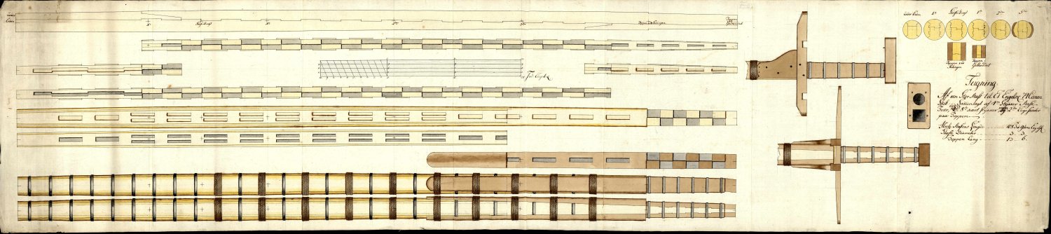
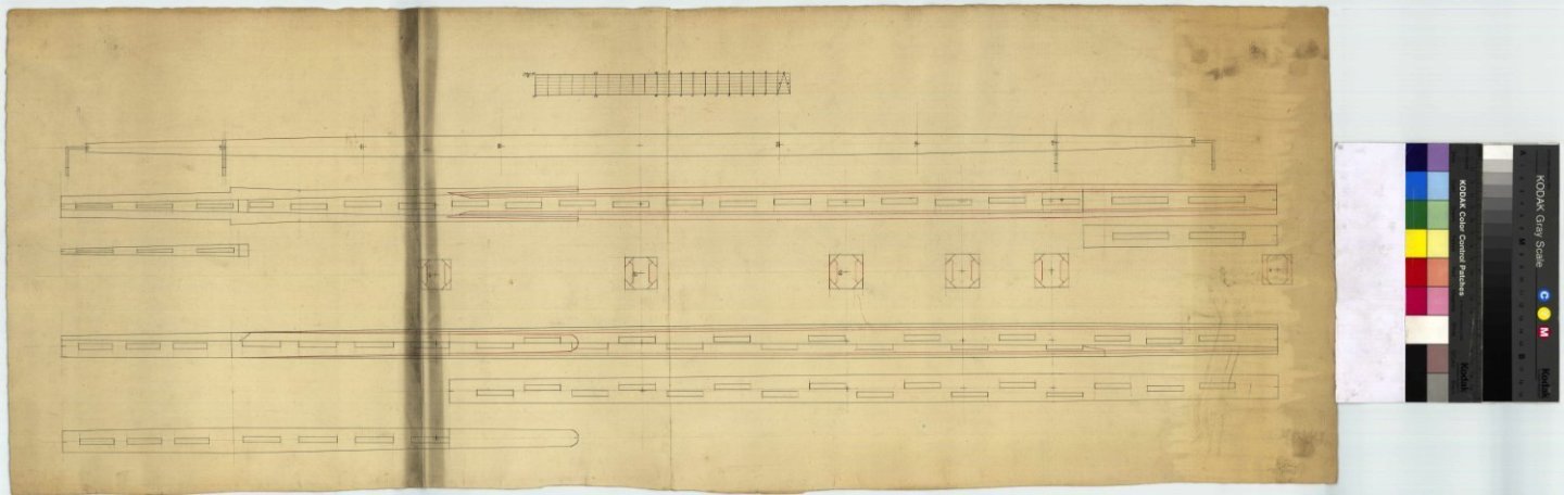
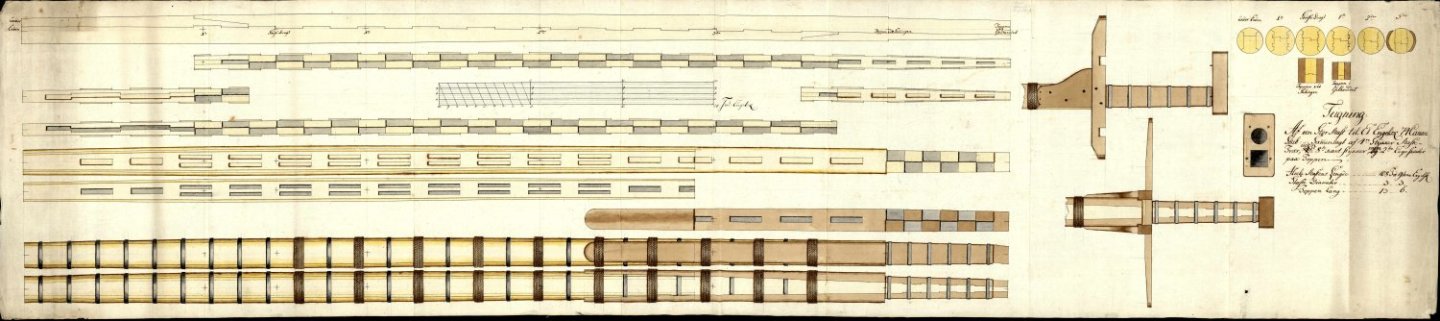
Construction of Masts for 18th Century 'Ships of the Line'
bruce d replied to tmj's topic in Nautical/Naval History
These drawings from the Danish archives may be of help. D206 is for English ships '80 and 100 guns', undated but from late 18th century: D201, as above but for 74 gun ships: G4728, more 74 gun ship masts: You can download hi-res copies free from their website: Arkivalieronline (sa.dk) HTH Bruce
-
Lovely model, Richard, and I like her just the way she is.
- 104 replies
-
- 3
-
-
- pegasus
- victory models
- (and 2 more)