
HOLIDAY DONATION DRIVE - SUPPORT MSW - DO YOUR PART TO KEEP THIS GREAT FORUM GOING! (Only 36 donations so far out of 49,000 members - C'mon guys!)
×


rwiederrich
-
Posts
5,518 -
Joined
-
Last visited
Content Type
Profiles
Forums
Gallery
Events
Everything posted by rwiederrich
-
I agree. A computer aided design of her would yield useful info. I had the idea of building a small model of her and comparing it to actual photos of her from similar angles as you suggested. I have a pretty good eye...so I always use imagery of her when measurements are not available. It all is close estimations anyway....until someone unearths her actual drawing made by McKay himself from some lost attic or cellar. Rob
- 3,560 replies
-
- 1
-

-
- clipper
- hull model
- (and 2 more)
-
You can easily see the add on additional 2 backstays. Wonderful clear example. Thanks Rich and Mike
- 3,560 replies
-
- 1
-
-
- clipper
- hull model
- (and 2 more)
-
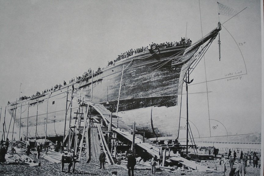
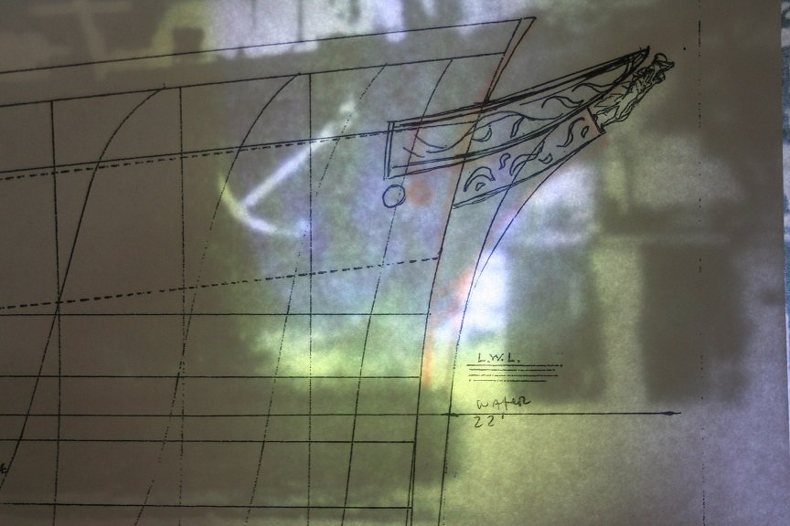
Several things Rich, You can’t use any of the buildings as references for plumb. Because in both images you cannot be sure of the hulls trim, nor it’s relationship to the buildings or pier. Next , I established the amidship waterline by extending the copper water line forward. It will not be parallel to the keel line because of vanishing horizon line. When viewing any object from any vantage point it always has a distant vanishing point. The visual deception is made when the curve of the ships hull bends the copper waterline in to the curve or round bow. But if you were viewing the hull at a waterline profile the waterline and keel lines would be parallel . By doing this math, I created an internal horizontal plane to establish the inclination of the bowsprit . If you look at the image you will see that the hull grows smaller as it travels down the ways to the stern. Every line you draw down the hull, though they maybe parallel , they always appear getting closer as they reach the stern. This is the horizontal vanishing point. See how I figured it out?
- 3,560 replies
-
- 1
-
-
- clipper
- hull model
- (and 2 more)
-
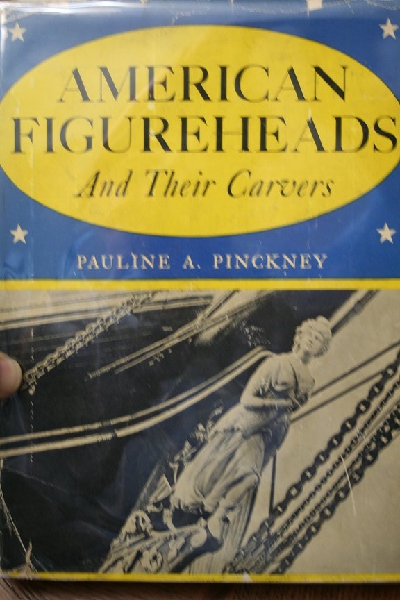
I forgot to post an image of this wonderful book I have...about figureheads. You might want to get a copy for your own library. Rob
- 3,560 replies
-
- 3
-
-

-
- clipper
- hull model
- (and 2 more)
-
One last note of importance....I was able to determine from the amidships waterline that the bowsprit's angle is 23 degrees. Nearly the 22.5 degrees what Mike claims. We can't be that far off...really! Rob
- 3,560 replies
-
- 1
-
-
- clipper
- hull model
- (and 2 more)
-
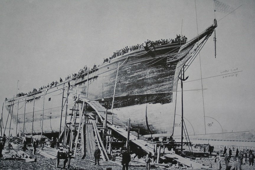
Interesting...what are you using for your vertical plumb to establish the 20 degrees? You could be using the buildings..but that doesn't guarantee the ship is trim in the water. I'm revisiting my original drawings and measurements and I'm finding that through refinements I have come to the determination that her stem is not my original estimation of 7 degrees but 8.5 degrees. I redrew with better accuracy the keel horizontal...which will induce error in all other measurements. They too have been corrected now with the new data. I've determined that her inner bobstay plate is the same distance from the original copper line as is the length of her figurehead....90". Depending on what image you are looking at, her naval hood is roughly twice the length of her figurehead....180". It appears her copper line had been raised 45" by the time her picture was taken when she was fitting out in 1911 for her Alaska sailing. This is noted by the over coppering of her outer bobstay plate, which is not how she was originally coppered. I'm having so much fun researching all the changes to the Glory..when they were instituted and the like. It wasn't till Mike came over that I even learned that Glory had a mod that added 2 backstays to her fore and main masts...that didn't go through the existing channels, but were simply bolted to her side like a British clipper....Fun info. Here is a new image with some new lines on it. Keep up the good work.
- 3,560 replies
-
- 1
-
-
- clipper
- hull model
- (and 2 more)
-
I have friends who build in this scale...it actually makes for very fine models. I was planning on using my vacuum former to make copies from a *Master* model. In this way I can make several hulls exactly the same and then work the deck as need be. the models would be small enough to occupy the same base...but show the distinct differences as she evolved. The entire project would be in of itself one single display by itself. I utilized this method when I was commissioned to build a model of the steam skiff *Puffin* for the Seattle Wooden Boats Maritime Museum. I calculated around 6".....maybe it is 1/600. 1" = 50' 5.3" I'm a simple man.... Rob
- 3,560 replies
-
- 1
-
-
- clipper
- hull model
- (and 2 more)
-
Yes...that is a famous painting. I've read that since the Confederates traded with England....they would capture clippers even in their ports and destroy them. Not to mention any that tried to make it past their blockade to the south around the horn. It is a true sadness that the war decimated, not only the clippers but our dominance in world trade.
- 3,560 replies
-
- 1
-
-
- clipper
- hull model
- (and 2 more)
-
Yes...and we can thank the American Civil war for that as well. Hundreds of clippers were taken or burned as victims of war by the South. Mike tells me that he is getting a grip on his collection and that he will, in some time, be able to track down some more images. He thinks we are coming along nicely and that the corrections I've made make sense and are bringing us closer to Glory's true design. I hope to make several small models(Possibly 1:700) of her as she was originally built and as her final configuration....to provide a true comparison of her evolution. Rob
- 3,560 replies
-
- 1
-
-
- clipper
- hull model
- (and 2 more)
-
This figurehead is from the clipper America. She was totally white and is now at a resort called Rosario in the PNW. Beautiful
.jpg.e40d872c9eefdf3a3d7411548f8c2086.jpg)

.jpg.e02db1a3852d86dece4618ec58662fd2.jpg)
- 3,560 replies
-
- 2
-
-
- clipper
- hull model
- (and 2 more)
-
That deck house measurement wasn't for clippers...just an example of how designers used symmetry in constructing their vessels. I was referencing the WIDTH of the cabin not length. It was easy to use body parts as measuring tools....and ship parts were utilized in the same way. Pretty cool huh? Rob
- 3,560 replies
-
- 2
-
-
- clipper
- hull model
- (and 2 more)
-
Interesting note to ponder. It was not uncommon for captains to paint the figurehead prior to entering port. This detail was left up to the privy of the captain. I tend to think....from painting evidence and those of first hand recollections, that she was originally all white....similarly like the Cutty Sark. She too was repainted when she fell to Portuguese ownership as the Ferreira....dark hair and a blue dress. This might be taken into account... the dark hair and gold trim of her flowing gowns fringe. Regardless....white paint would have been easiest......though I think I recall reading somewhere, her being repainted with bright red lips and cheeks once. Rob
- 3,560 replies
-
- 2
-
-
- clipper
- hull model
- (and 2 more)
-
My calculations place it roughly at 24' as well. 3' before the first band and 3' past the 7th band. 8, 3' spaces equal 24" Rob
- 3,560 replies
-
- 2
-
-
- clipper
- hull model
- (and 2 more)
-
Rich... that is actually 9' from the inner bobstay eyelet, 12' from the outer. Those eyelets were probably bolted through the iron bands for strength. Rob
- 3,560 replies
-
- 1
-
-
- clipper
- hull model
- (and 2 more)
-
Good information. That 3' band distance is good to know when calculating head gear and hood dimensions. I emailed Mike about what I've been up to and hope he jumps in here to see. I didn't post any of my images directly to him via email. He and Arina check these pages often I think. I can't post too many images from work to his email. Thanks for all your work and communications with Mike...it helps a lot. Rob
- 3,560 replies
-
- 2
-
-
- clipper
- hull model
- (and 2 more)
-
Beautiful Michael.....can't wait to see what you do with her. Rob
-
Several interesting notes. Her inner bobstay mounts to the bowsprit roughly 7.5ft (90")from the head of the figurehead...which happens to be the length of the figurehead. Also noted is that the distance from the head of the figurehead outward from the vertical from the cutwater(entrance of the hull into the water or copper line) is exactly the same distance as the length of two figureheads or 180". One thing is for sure(and this was true for many clipper builders), they built them utilizing their own measurements. Meaning the length of a foremast from the prow of the forecastle was the length of the lower foremast, or the width of deck houses was the distance from foremast to mainmast multiplied 4 times. Lots of unique measurement tricks allowed the shipwrights to keep things simple, yet elegantly balanced. Rememberable.
- 3,560 replies
-
- 1
-
-
- clipper
- hull model
- (and 2 more)
-
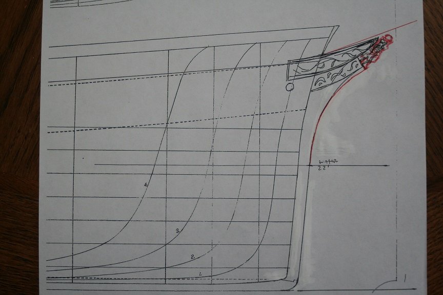
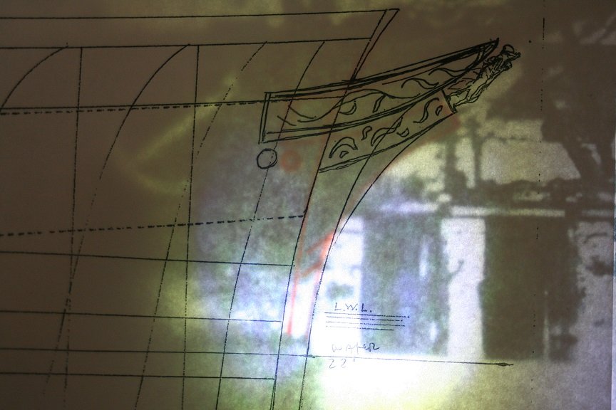
Playing with the new images...I took some measurements and using the figurehead as the foundation and the height of the copper line I was able to make some changes to my drawing that better mimics the San Pedro image. As you can see I altered the stem to have more of a parabolic curve...being more vertical exiting the water and then making the curve up and forward to the foot of the figurehead. The figurehead is a sloppy mess...but is 7.5ft long and the hood's length is 2 and one third the length of the figurehead. The copper line to the false keel is 22ft. Scale is 1/8" to 1'------
- 3,560 replies
-
- 1
-
-
- clipper
- hull model
- (and 2 more)
-
Great images for sure. That first is when she is being fitted out for Salmon factory service. It gives us a clear view of her naval hood and the bowsprit. wonderful. The jib-boom's root is better seen here as well. I'll take some new measurements and try to validate some things...using your figurehead idea. Love it...we are getting much more info for a much better model. Rob
- 3,560 replies
-
- 1
-
-
- clipper
- hull model
- (and 2 more)
-
Richard..... Great observations and clear imagery. I went back to the enlarged image of San Pedro and imposed my corrected drawing over it. Now apart from accepted distortions...I think I got pretty close. My drawing is set at the waterline... You can see that the figurehead is slightly lower on the San Pedro image. I also have determined that the curve of the stem is more of a paraboloid as I had originally imagined. Making the curve slightly concaved from a true circle. The bobstay plates are pretty close to were they would be...if you reference her pre launching image...compared to her copper line. The location of her figurehead is pretty close to what I had imagined from other images. I'm gather its true location is somewhere in the middle of the two imposed images. The pink lines are drawn on the San Pedro image outlining her lines. Any thoughts?
- 3,560 replies
-
- 2
-
-
- clipper
- hull model
- (and 2 more)
-
Great job...... I wonder if anyone ever considers making the Star as a full rigged ship as she was originally built? Rob
-
Michael, Not to be nitpicky, but if you notice your seat cushion compared to the actual one on the real boat...you will notice your model has a finish board along the front of the cushion, I noticed this earlier but didn't want to say anything. But a person would *Pinch* the back of their leg against that uncomfortable finish board. The image you posted of the real boat shows a cushion with a pleasant soft edge. It looks like your seat cushions might need to be a bit longer. Compare the two and you'll see what I mean. Apart from that your model is extremely beautiful and the details impeccable. The image you posted of the real boat makes me drool.......... Rob
-
Fantastic! I need to see the new images first. Mike didn't send them to me. Rob
- 3,560 replies
-
- 1
-
-
- clipper
- hull model
- (and 2 more)
-
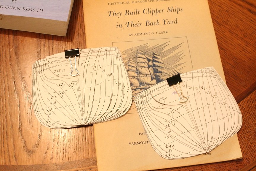
Yep Abe Books. I love finding these small pamphlets. Many times they contain more personal information. Information that can get left out of larger more general information publications. When I was researching for my Great Republic build, I cam across this pamphlet written about single family builders of clipper ships. Fascinating read. many smaller yards jumped on the bandwagon to make fast clippers. That was were the money was.
- 3,560 replies
-
- 2
-
-
- clipper
- hull model
- (and 2 more)