HOLIDAY DONATION DRIVE - SUPPORT MSW - DO YOUR PART TO KEEP THIS GREAT FORUM GOING! (89 donations so far out of 49,000 members - C'mon guys!)
×


Tomculb
-
Posts
346 -
Joined
-
Last visited
Content Type
Profiles
Forums
Gallery
Events
Everything posted by Tomculb
-
 Very nicely done Josh, definitely a build to be proud of. Averaging maybe 5 hours a week, I doubt that I will have finished my Spray before maybe mid-winter, but who knows. Regardless of the pace, she is certainly a fun build. I'll be interested to see what you choose to build next. Happy Thanksgiving.
- 70 replies
-
- 2
-

-
- Spray
- bluejacket shipcrafters
- (and 1 more)
-
Thanks Josh. I do like to use color sometimes to highlight detail, but I have to be careful not to overdo it and not stray too far from what has at least some chance of being historically accurate. As to the latter of course, as Nic mentioned on your log, we have to rely mostly on speculation when it comes to Spray, since there is so little authoritative material to rely on. Also, I stumbled upon your profile recently, and it appears that we are at opposite ends of the same state. I'm in Spokane.
-
Nic, I did give some thought to vinyl tape, but not having any handy, I moved on thinking I'd come back to the idea, but I had kind of forgotten all about it. Thanks for suggesting it. Taping the water line would have the additional advantage of covering the occasional ragged edge I have now. Doing a little digging in these forums, Chartpak tape came up several times. And some suggest adding a coat of polyurethane or shellac to make sure it adheres indefinitely. Any recommendations on the subject?
-
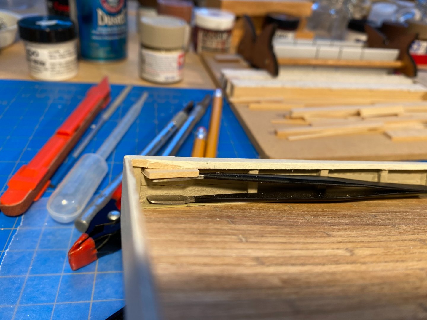
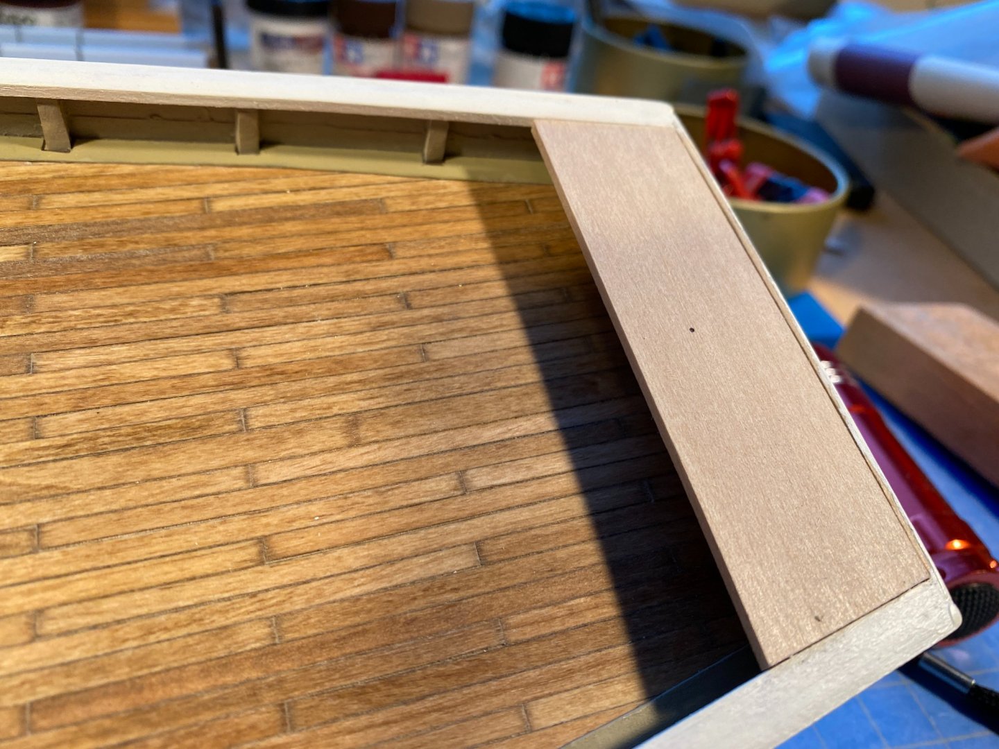
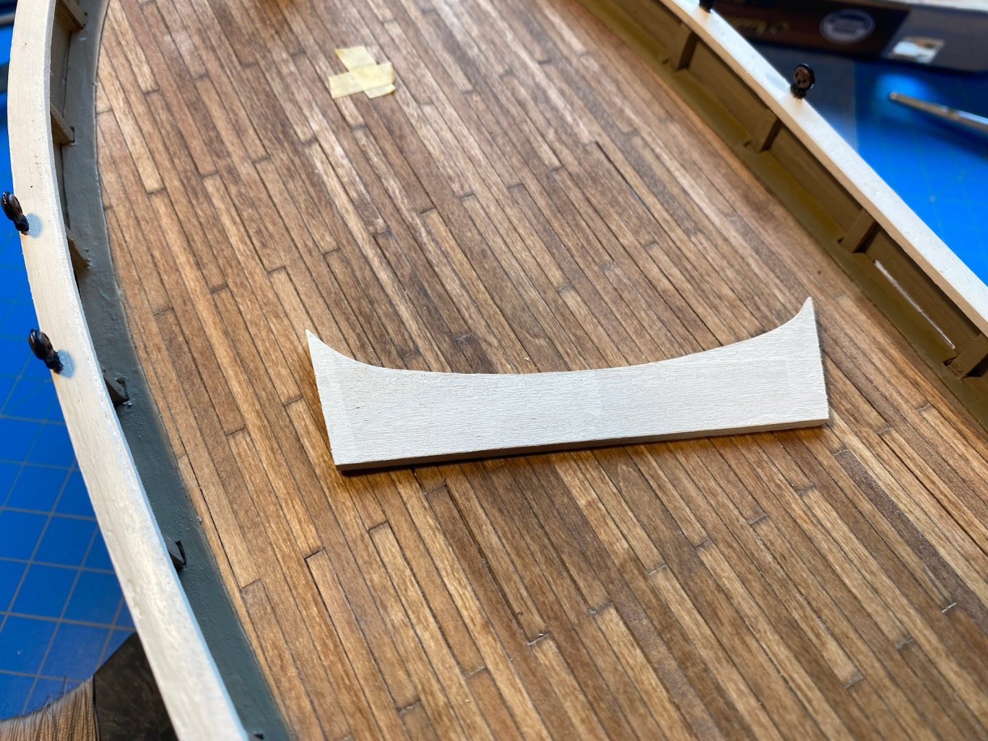
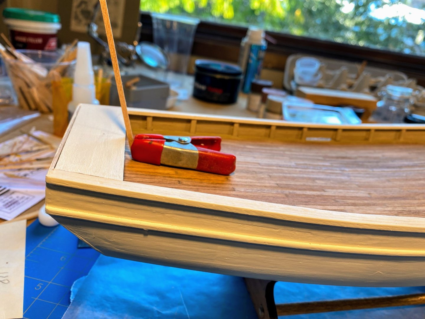
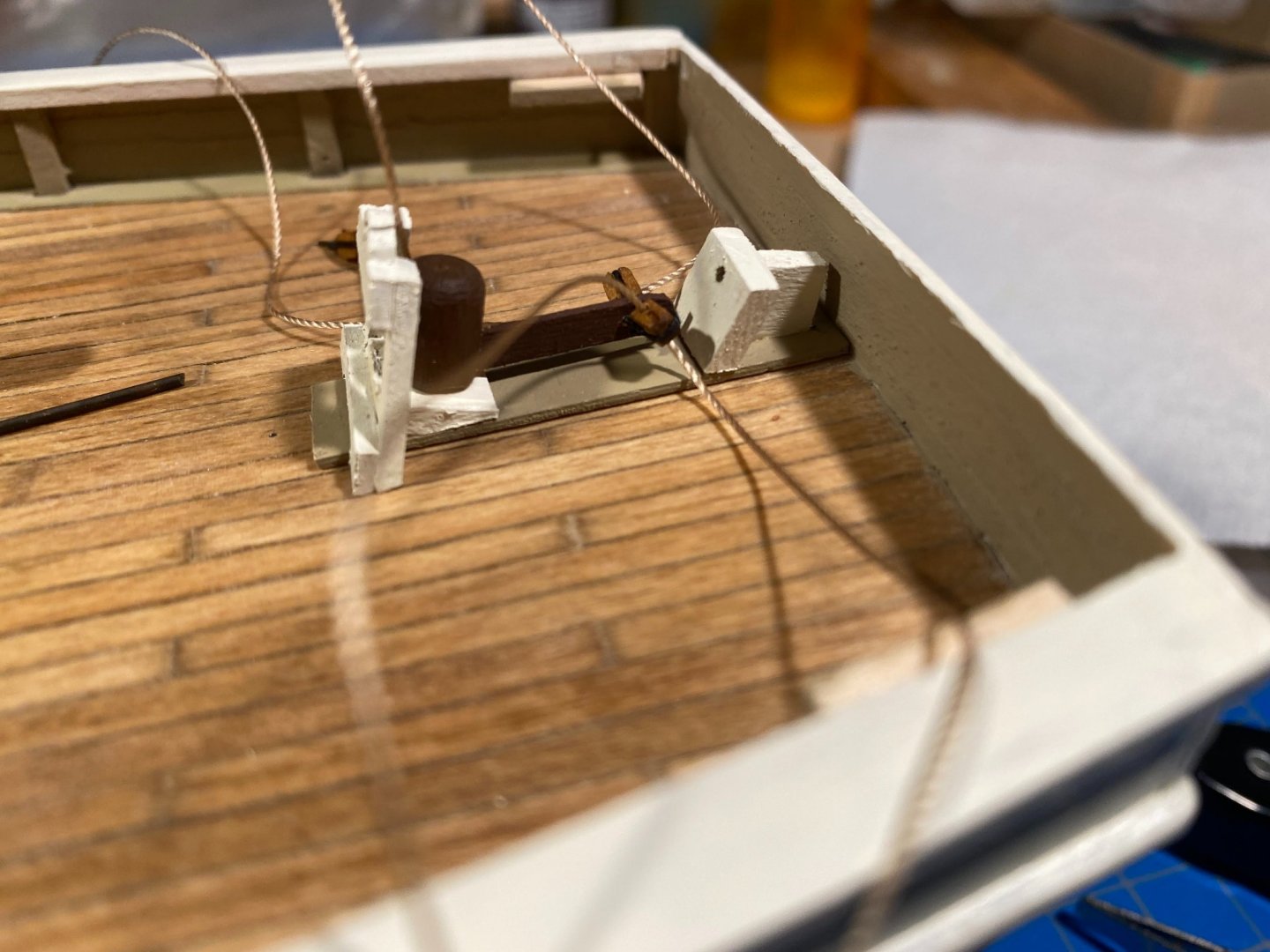
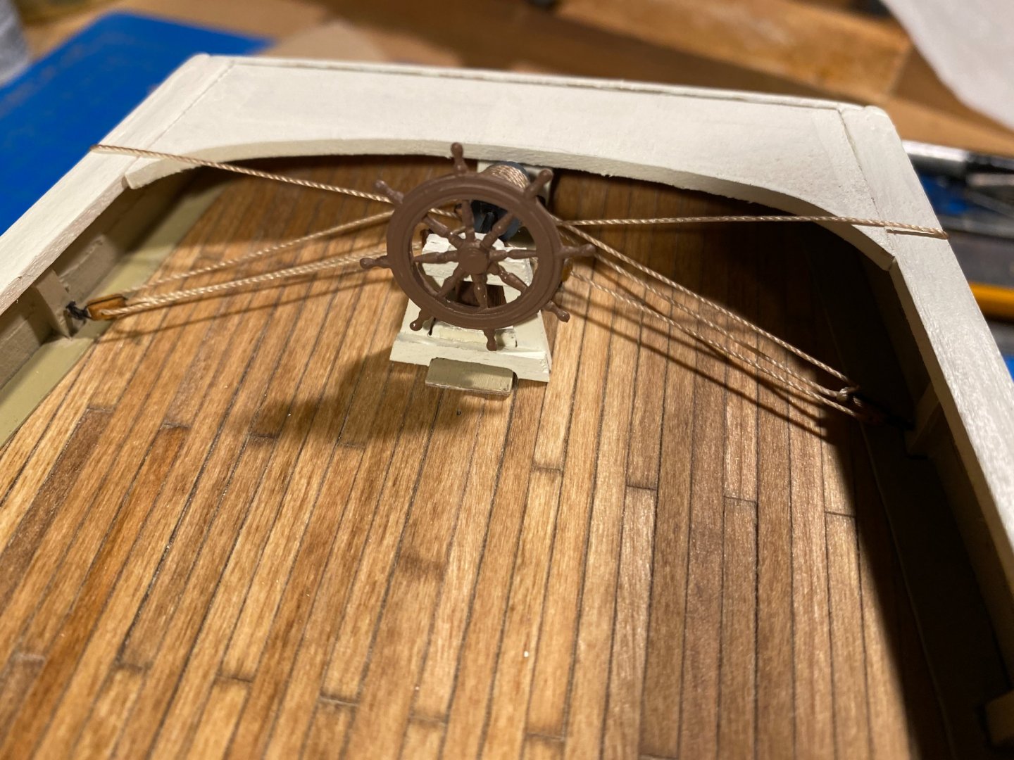
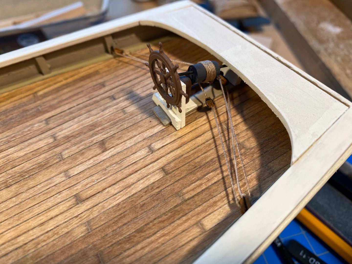
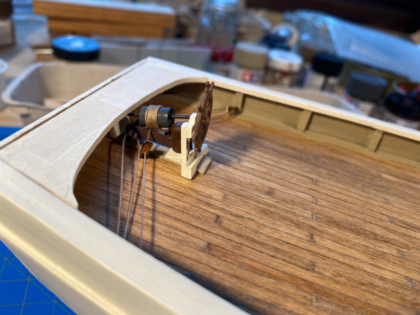
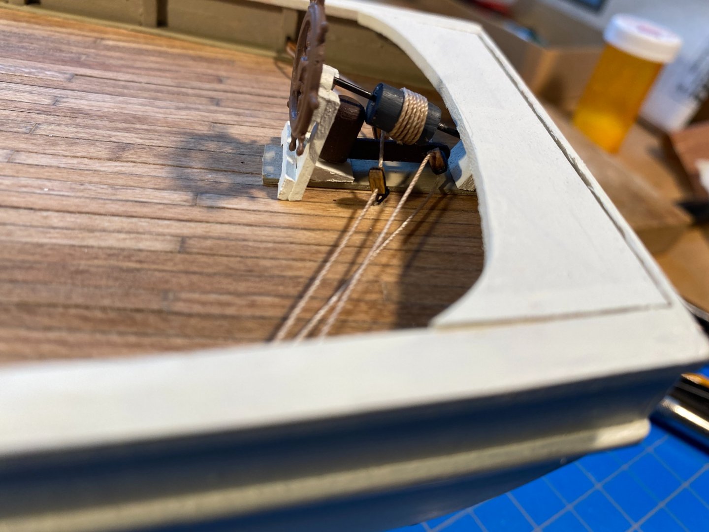
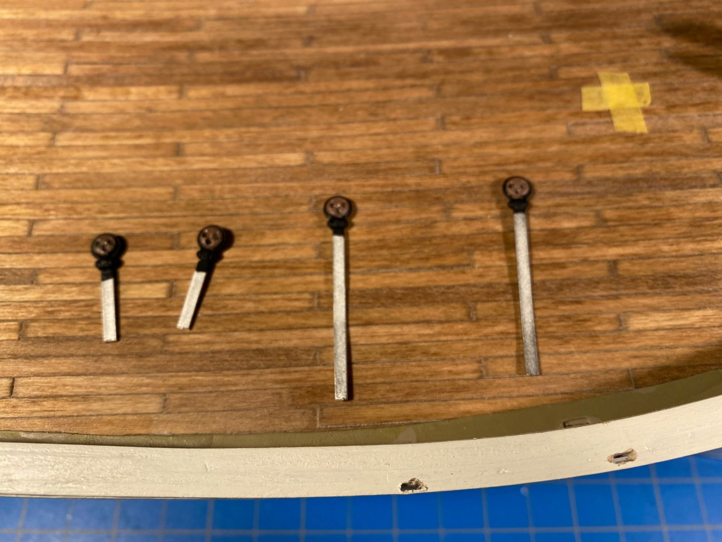
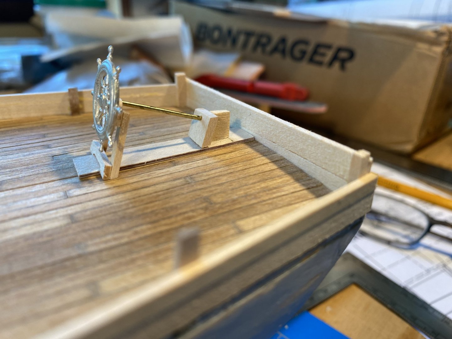
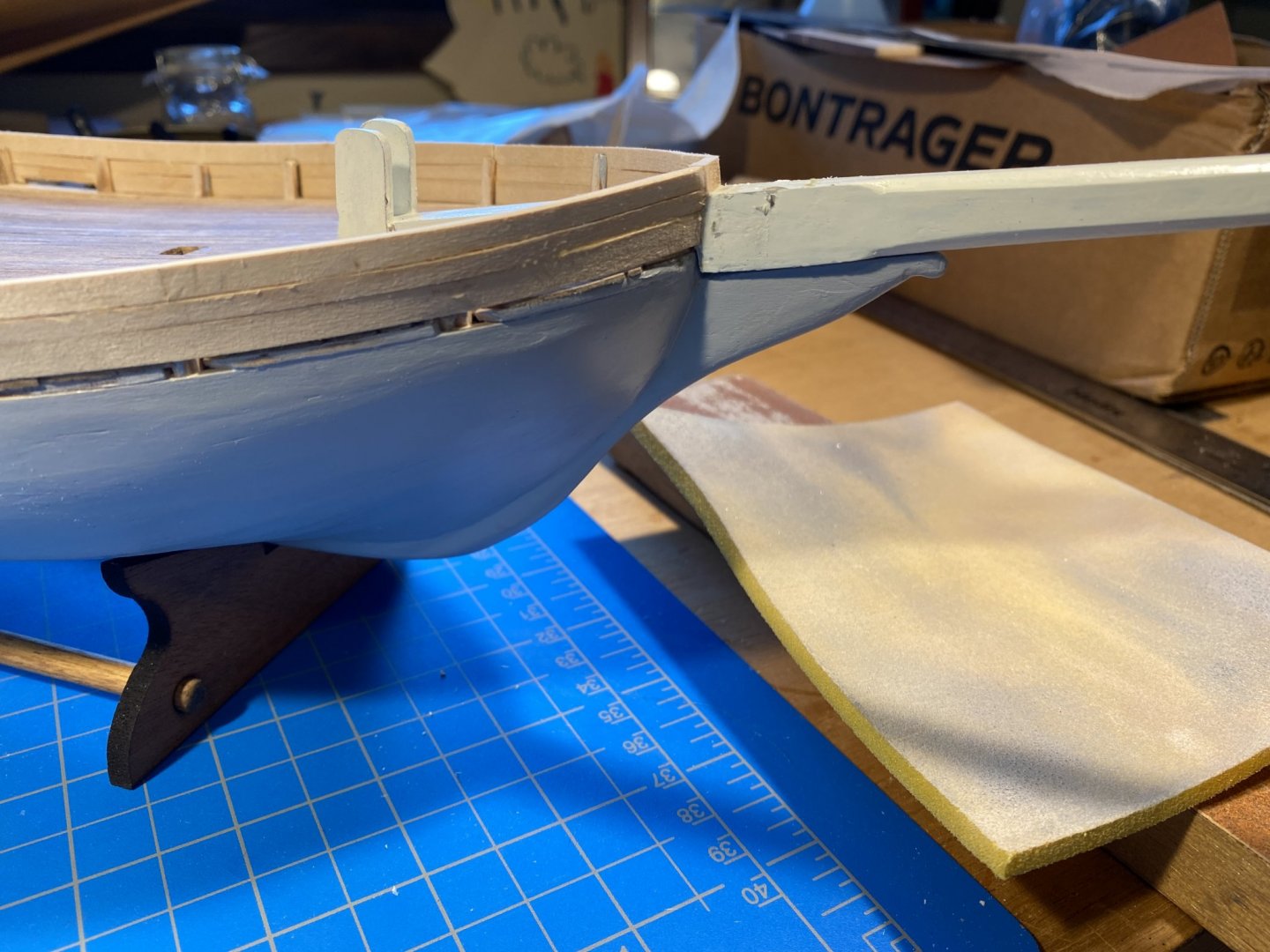
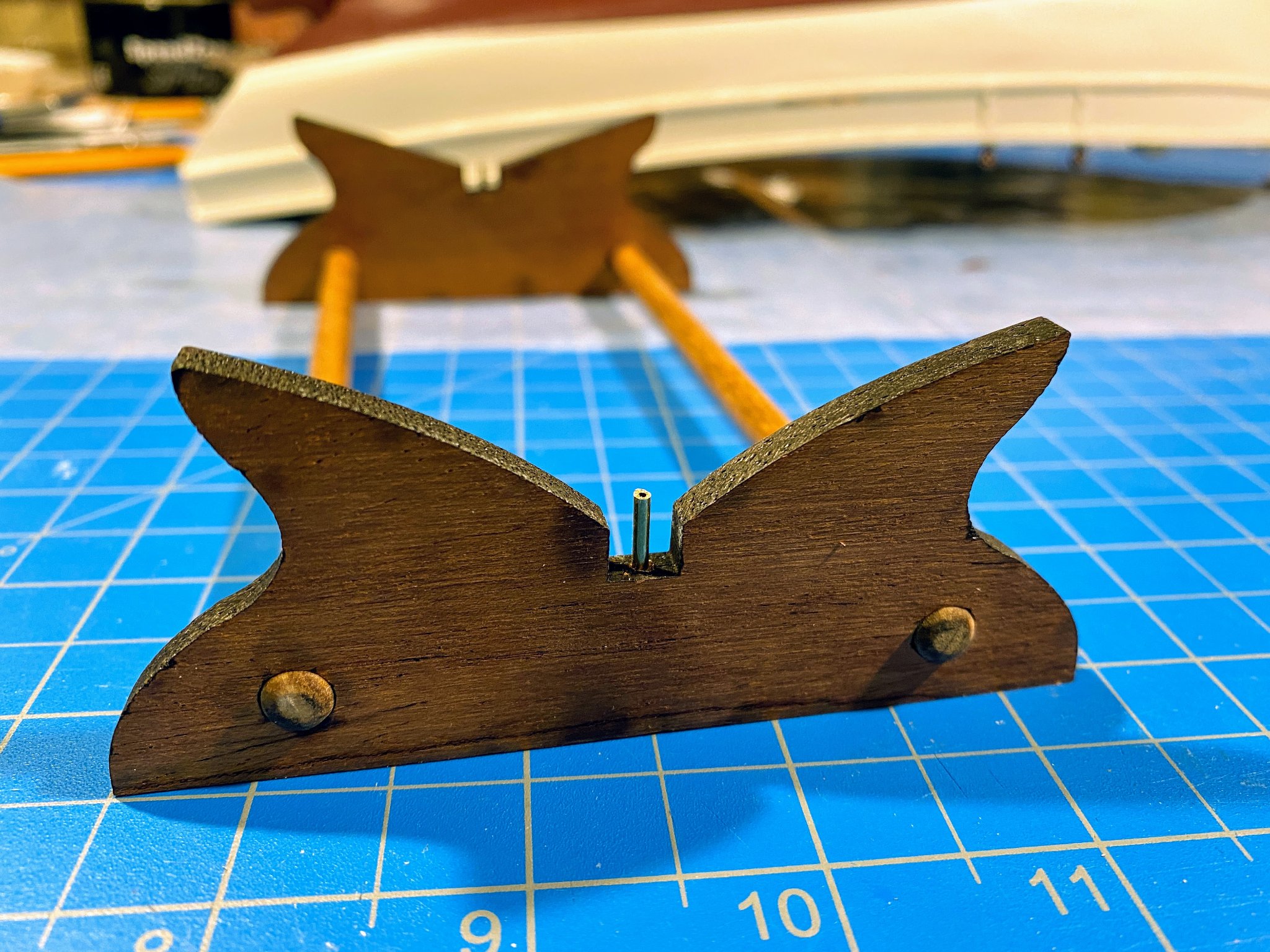
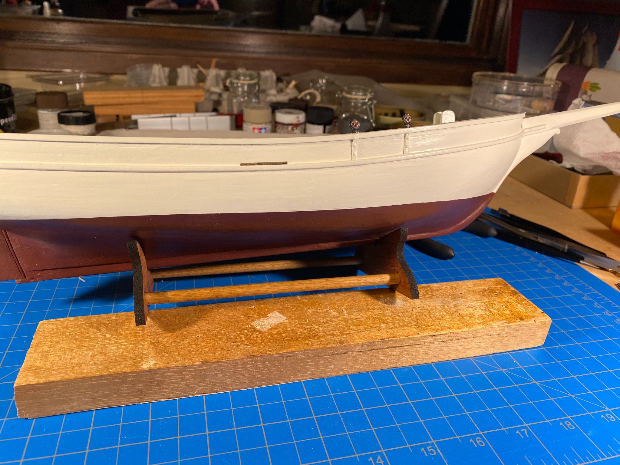
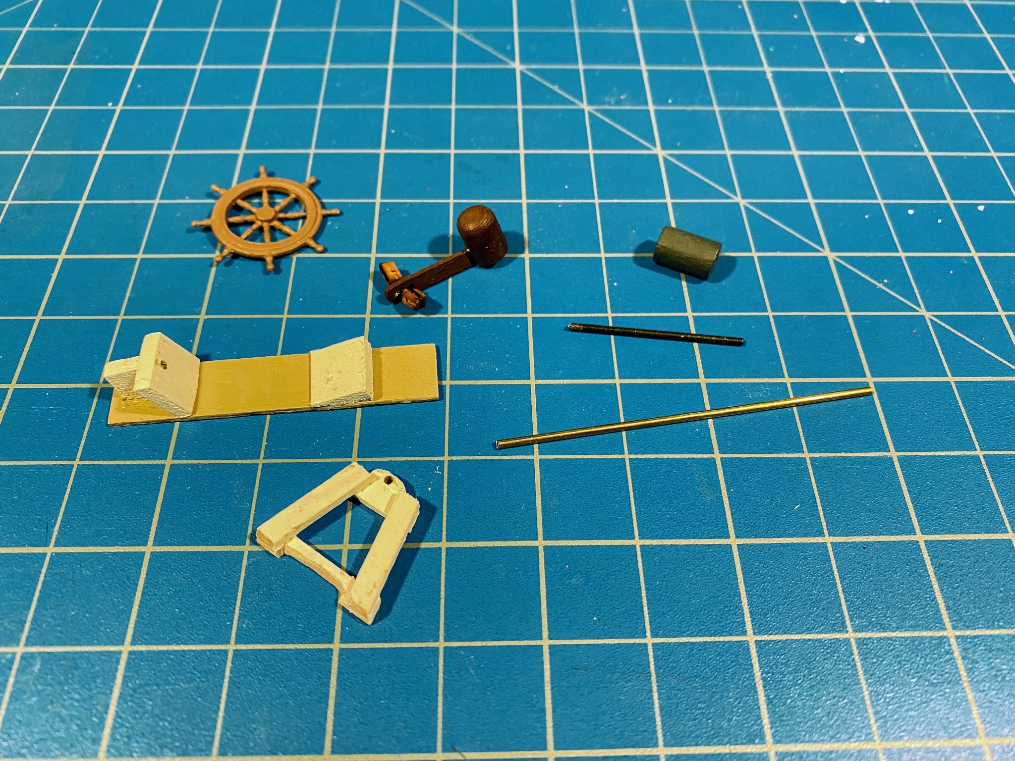
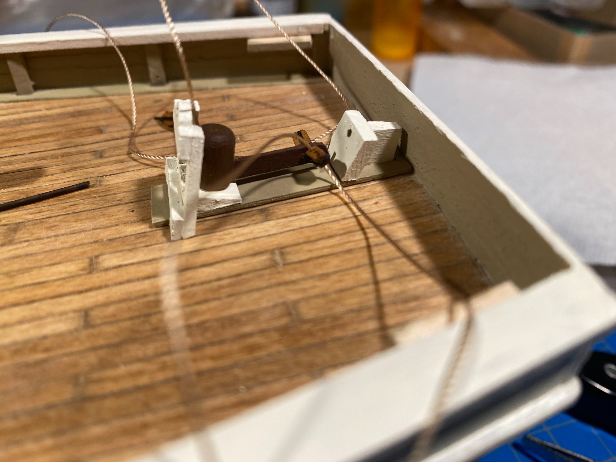
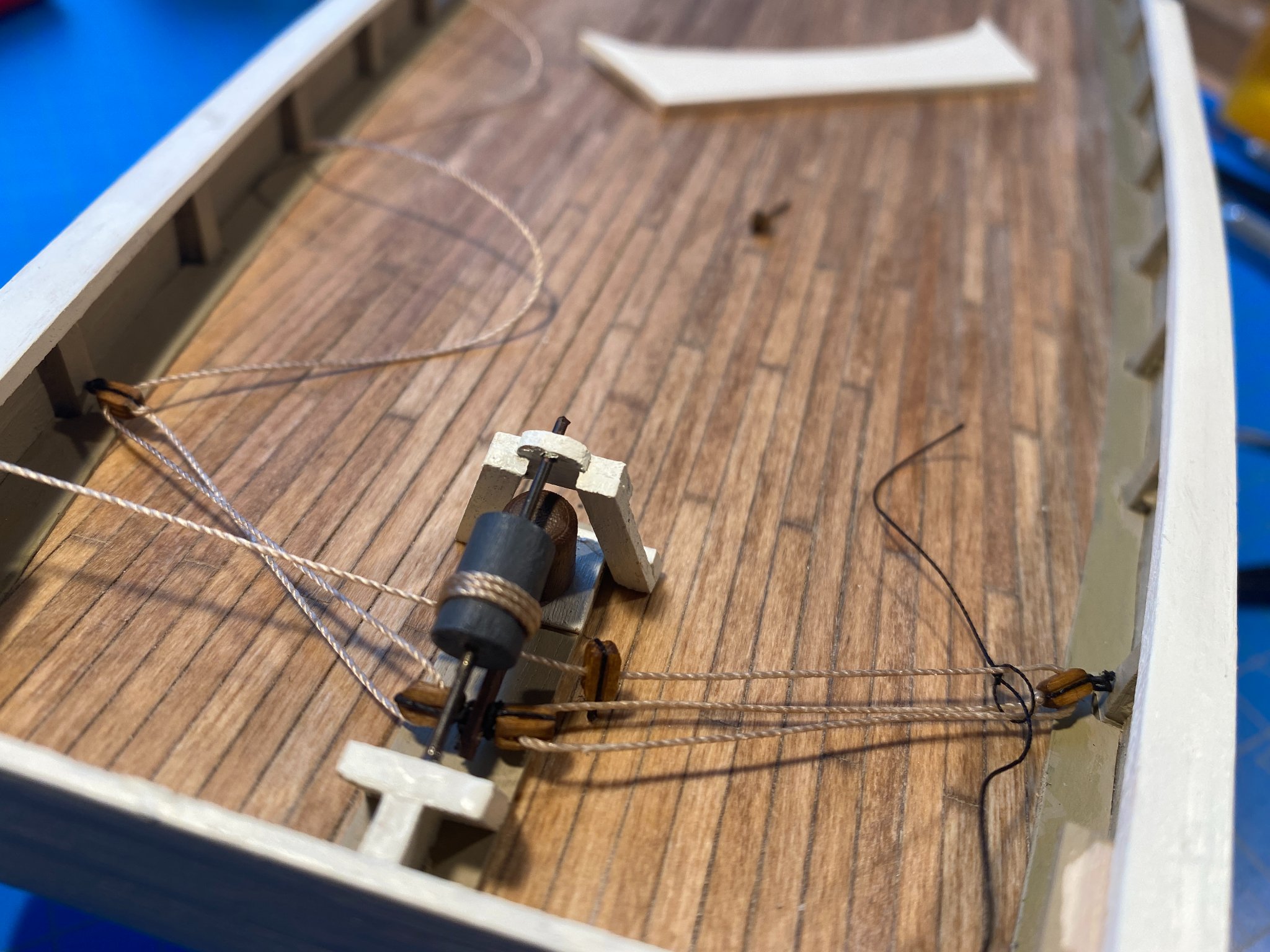
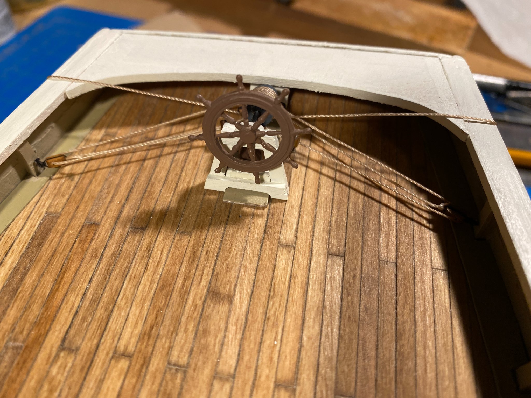
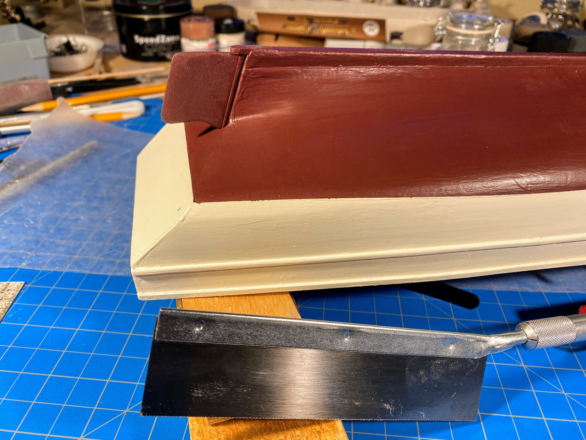
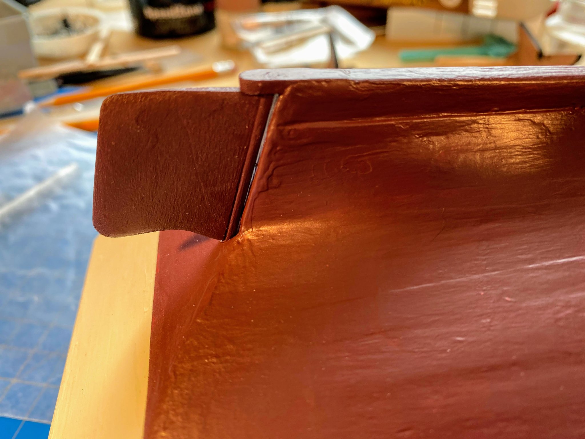
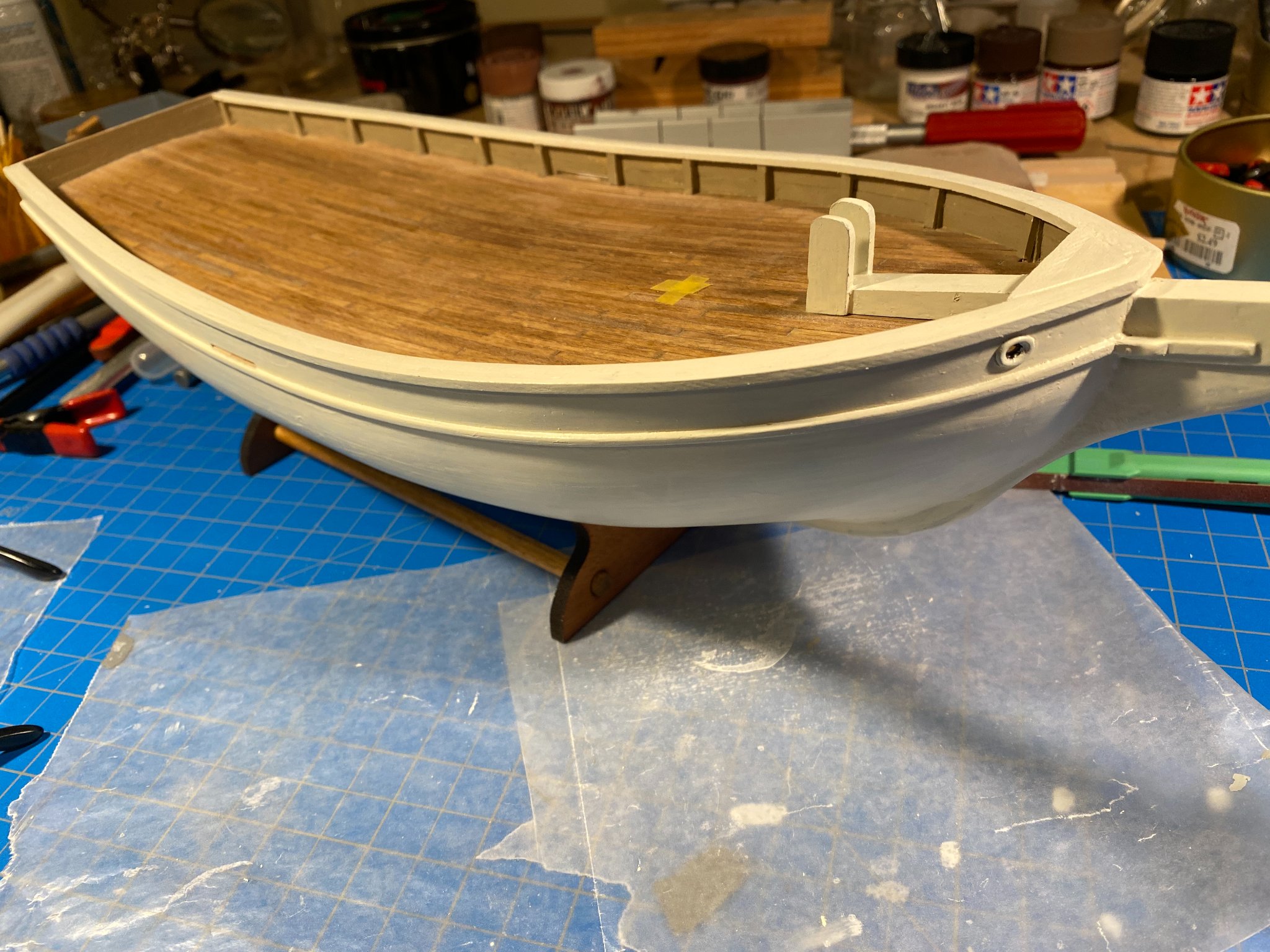
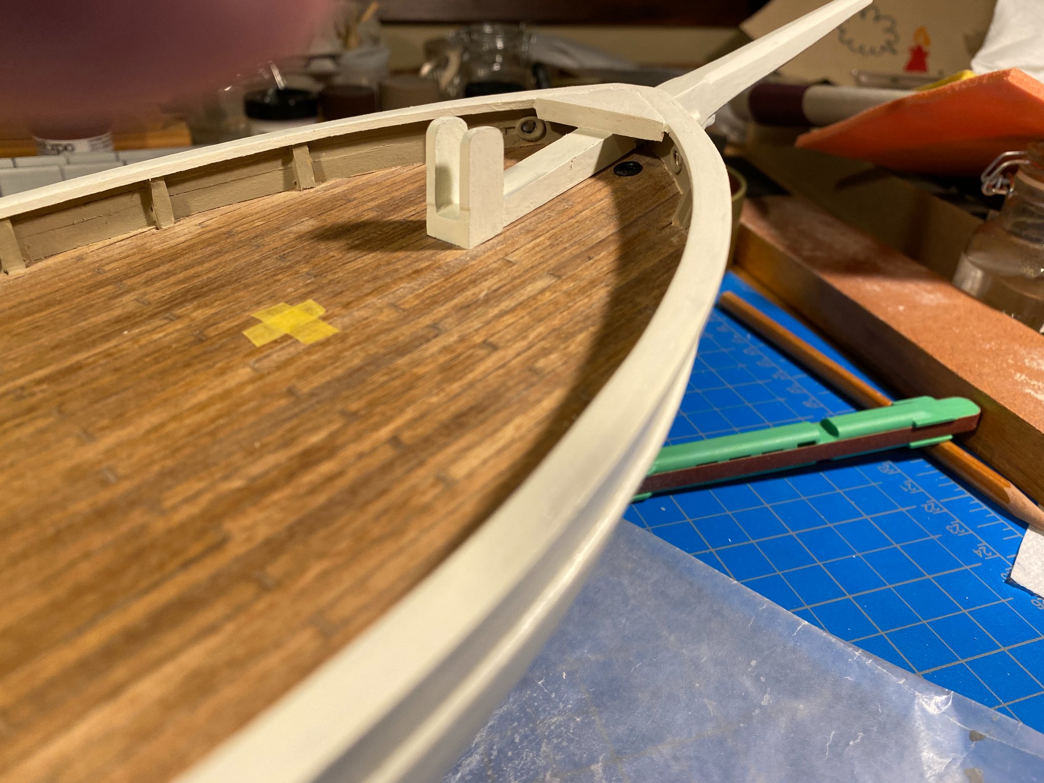
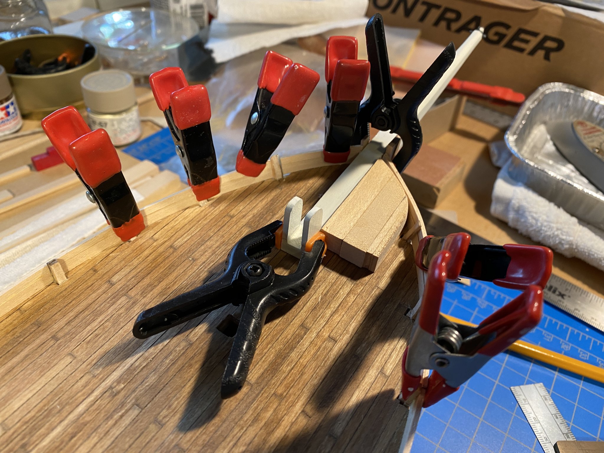
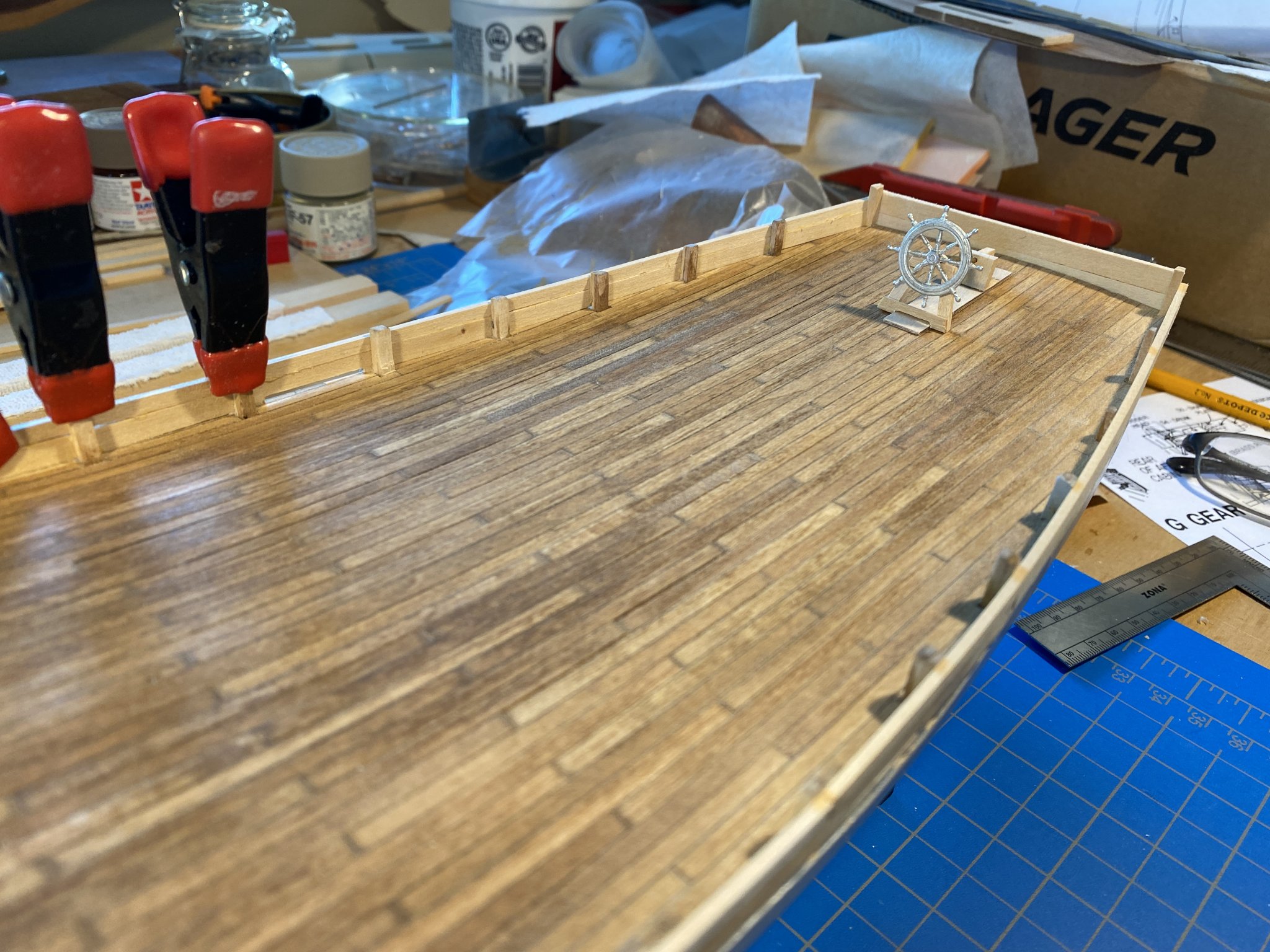
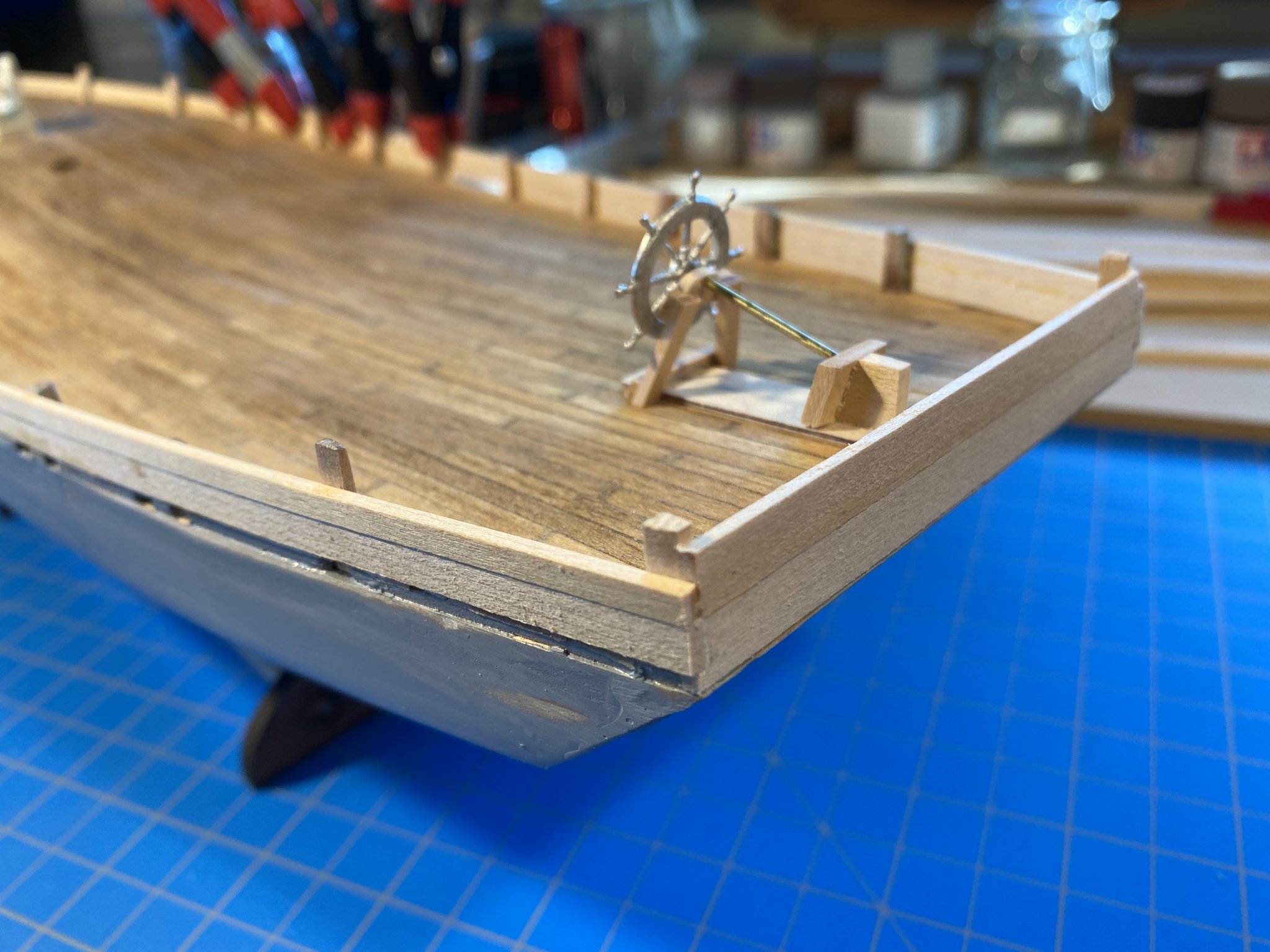
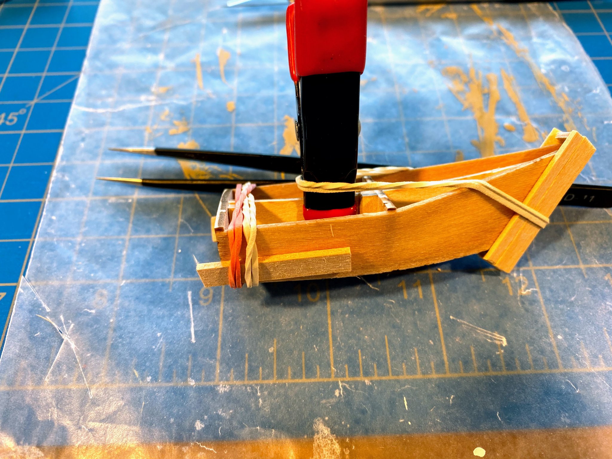
A note on my previous post (painting the hull). I had thought I was going to paint a waterline stripe, but seeing how the tape I used struggles with sharper curves, and foreseeing the difficulty of making two strips of tape manage those curves at a precise distance apart (say 3/32”), Spray will just have to do without a waterline stripe. I also realize that I approached that feature incorrectly. I should have started my painting with a black, imprecise but wider (say ¼”) stripe, then covered it with a single strip of tape of the chosen width, then painted white above the tape and anti-fouling maroon below. Problem with that, though, is whether I could get the white to adequately cover the black of the waterline. An issue to be addressed on a future build, and who knows, maybe this will be my last one with white topsides. I think I am now at the beginning of the most fun part of the build, where accomplishments and projects take weeks or days (or even hours) rather than the year it took me to complete the hull. 😃 While still painting the hull, I took a few breaks to work on the taffrail (or is it more properly a taff“deck”?). I cut it from some 3/32” stock, using the edge of the sheet of wood for the rear edge, my fine tooth crosscut saw for the sides, and an X-Acto knife for the longer, forward edge (which was pretty easy, going with the grain). I then used a couple of scraps to build shelves under the inner edges of the toprails, and dry fitted it into place. Of course I still had to cut the curved line I traced on the leading edge, a little more of a challenge. A few weeks earlier, noticing that one of the gaff jaws and the two “brace brackets” (that will one day extend aft of the transom) are oddly not laser cut, I bought myself a jewelers coping saw online. It came with 120(!) blades, and reading a bit about this tool, I learned that it is not a question of whether you will break a blade, but rather how frequently you will do so. Thus well-informed, I picked a courser one of the blades, and began sawing along the line I had traced from the plans. I quickly realized that following that line precisely will take some practice, so I erred outside the line and ended up with a rough approximation. The sawing was actually easy and quick, just a little ragged. That was remedied with some sanding, and the end result was pretty good. And I didn’t even break a blade! At about the same time (before the rudder was installed), I eyeballed where the top of the rudder post should penetrate the deck (not that it actually will penetrate the deck). Handy thing to have done that, some weeks later when I was ready to install the steering apparatus. Next project, affixing the stand (assembled kit parts), while I am still comfortable turning the boat upside down. Not having a drill press, I wasn’t confident of my ability to drill holes straight from the bottom of the stand’s end pieces all the way up and into the hull. And I don’t think I have any screws that are both thin and long enough to work that way. Instead, I took a couple of small nails with sharp points, cut the heads off, drilled very small holes in the notches in each end piece, and pushed the nails in, point up. I had previously established where the stand needs to attach to the hull for the waterline to be horizontal. I then turned the stand upside down and pressed it against the hull at the appropriate place, resulting in two precisely spaced pin pricks in the bottom of the hull. Then using a trick I came up with on my previous build (Model Shipways America), I drilled the starter holes in the hull and the stand just enough larger to be able to force a couple of short pieces of 1/16” OD brass tubing in. Not as secure as screws, but no way the stand and hull are going to separate without some intentional effort. Now on to that steering assembly. A couple of months ago I posted a picture of some of it assembled and dry fitted on deck. It took a little more work than I expected to build all the pieces, but I had numerous opportunities to do it when the only alternative was watching paint dry. The most interesting piece to build was the rudder post cap, with the tiller sticking out astern. You will notice two pieces of brass rod (one blackened) . . . . as Bob Garcia (a frequent contributor to these forums) appends to his posts, “Measure once, cuss twice.” The first issue that bothered me is that when you pull, from a fixed point, something that will describe an arc when pulled, as you pull less and less of the force is pulling it along the arc, and more and more of the force is trying, in this case, to pull the tiller off the rudder post cap, until you reach a point where none of the force is pulling along the arc anymore. An engineer (of which I am not) could probably describe that problem better. The problem is very counter productive here, because the more you move a rudder away from the centerline, the greater the force of the water against it. To reduce that inefficiency, I decided that the outer blocks needed to be ahead of the end of the tiller, not directly abeam of it. But put too far ahead, the line would rub against the aft corners of the aft deckhouse, and even short of that, the farther forward I put those blocks, the more likely Joshua would trip over the lines (I should probably give him more credit than that). I finally decided that I would affix those blocks to the furthest aft stanchion (other than the one in the aft corner). But that created a new problem. The lines leading to the drum would be approaching the drum at an angle, with the force eventually pulling the line forward and off the drum. So I decided to add a block on each side of the drum, so the line would load on and off the drum at a 90 degree angle. Brilliant I thought, until after I put those additional blocks in, and realized that they were in the path of the end of the tiller! So much for thinking things through. At least I think the helm can be put over to about 45 degrees without any significant interference. A couple of additional observations. Before I got started I decided I wasn’t capable to rigging this with only one line, as would be the case on the real boat. My fingers just aren’t small enough to take the line attached to the end of one block, lead it through a couple more blocks, wrap it around the drum, then back through some more blocks, and then (the real challenge) attach to the end of the block on the opposite stanchion, all while maintaining the appropriate amount of tension. So I used two lines, and with each one I took three wraps around the drum, hung the ends over the side of the boat with mini clamps attached to add some tension (see the picture above), and covered the lines on the drum with white glue heavily diluted with water. After letting it dry thoroughly, I snuck some sharp scissors under the drum and cut each line where the cut couldn't be seen. It held! Incidentally, the wheel in the pictures above is not yet glued in place. Seems likely it will get snagged on something quite easily, so I won't glue it on until later in the build. Second observation, and for me this took some considerable mental gymnastics. The line(s) wraps around the drum from the underside rather than over the top. Visualize this--turn the wheel to starboard and the drum pulls on the line on its starboard side (if that line wraps around it from below) and releases line on the other side. Pulling on that starboard line pulls on the tiller, which then moves to starboard. Since the tiller is attached to the back side of the rudder post (the opposite of every other tiller I’ve ever seen), it pulls the rudder (which is directly below it) to starboard, turning the boat to starboard. It took me a lot longer to convince myself I was right about that than it took me to write this paragraph.


- 82 replies
-
- 3
-
-
- spray
- BlueJacket Shipcrafters
- (and 1 more)
-
Nic puts it so well. Filler, sanding and paint do wonders; they certainly conceal a lob of unsightly gaffs in my Spray build. When I look at the logs of people building hulls that will remain natural and unpainted, I'm just in awe of what they are able to do. Keep up the good work.
-
Thanks for all the kind words of encouragement. I believe there are now five active Spray logs on these forums, and for every such log there have to be many boats being built by people who quietly sit on the sidelines or who aren't even aware that this website exists. I started my build a year ago so I can't say I was inspired by the Vendee Globe, but following the race now certainly puts an interesting perspective on Slocum's voyage. Or maybe it's the other way around. Working from home now due to the pandemic, between the race website open in a window behind what I'm supposed to be working on, and my model bench in another corner of the same room, it certainly is easy to be distracted.
- 82 replies
-
- 2
-
-
- spray
- BlueJacket Shipcrafters
- (and 1 more)
-
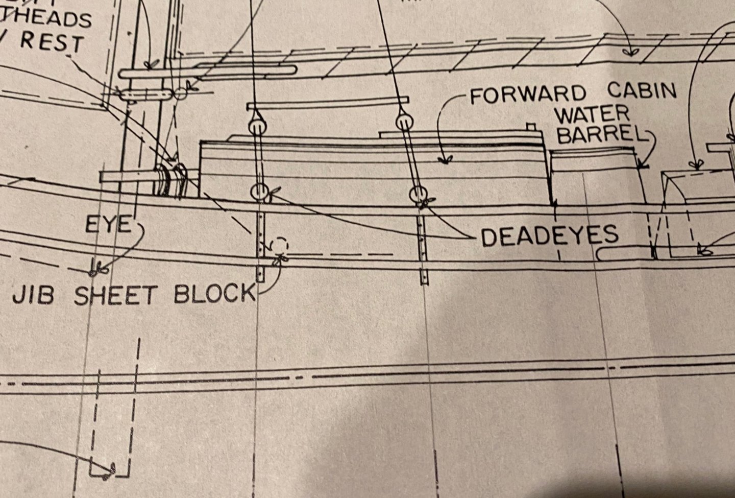
Nic, thanks from me too, because I was wondering the same thing. The fittings include a couple of large cleats, which I had planned to put on the deck a little forward of where you have the blocks for the steering apparatus. If not that, what are the cleats for and where do they go? Also with regard to the jib sheet, I had planned to attach a couple of blocks to the clew, start the sheets at the blocks on deck, run them up to the sheets blocks on the sail, and back to the blocks on deck before running aft. That jib seems like a lot of sail to pull in without the help of some block and tackle. Do you think I'd be wrong in doing that?
- 70 replies
-
- 1
-
-
- Spray
- bluejacket shipcrafters
- (and 1 more)
-
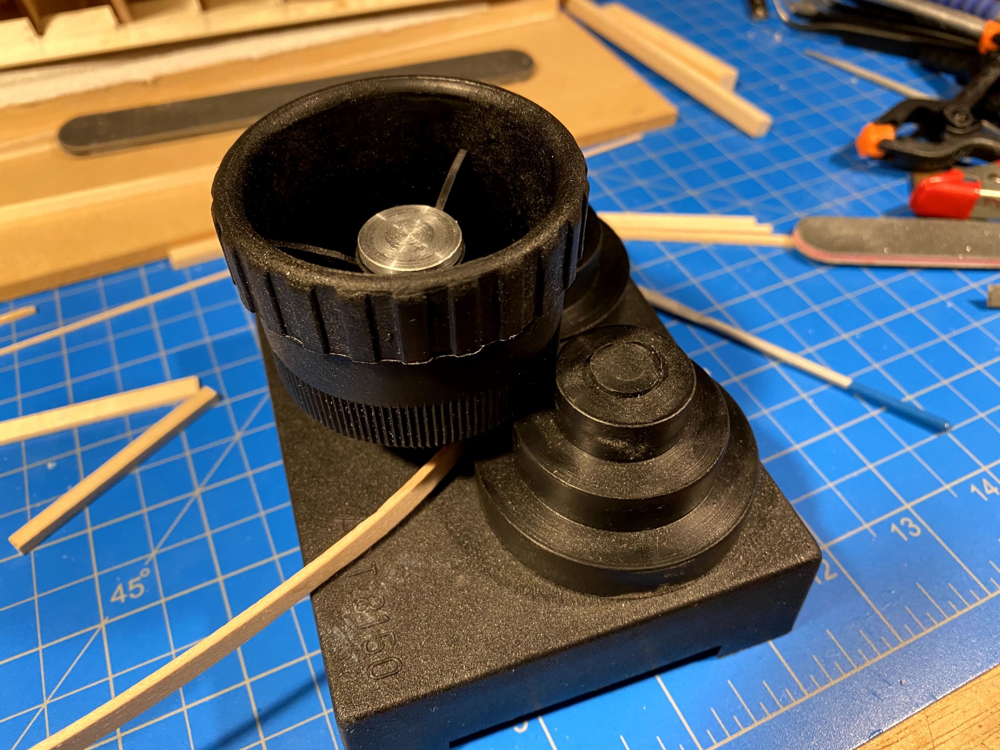
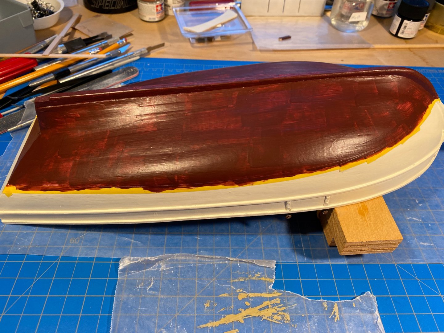
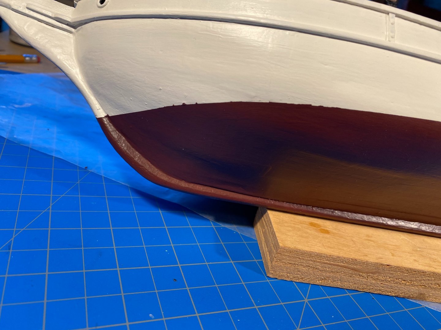
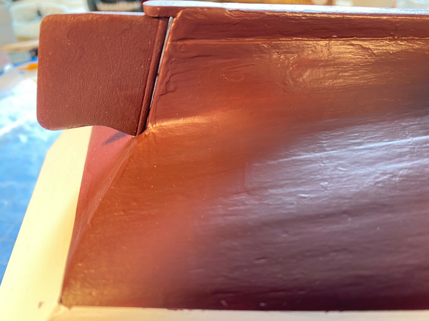
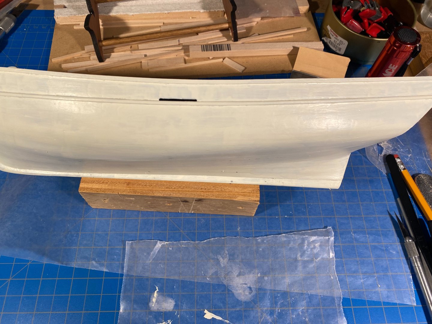
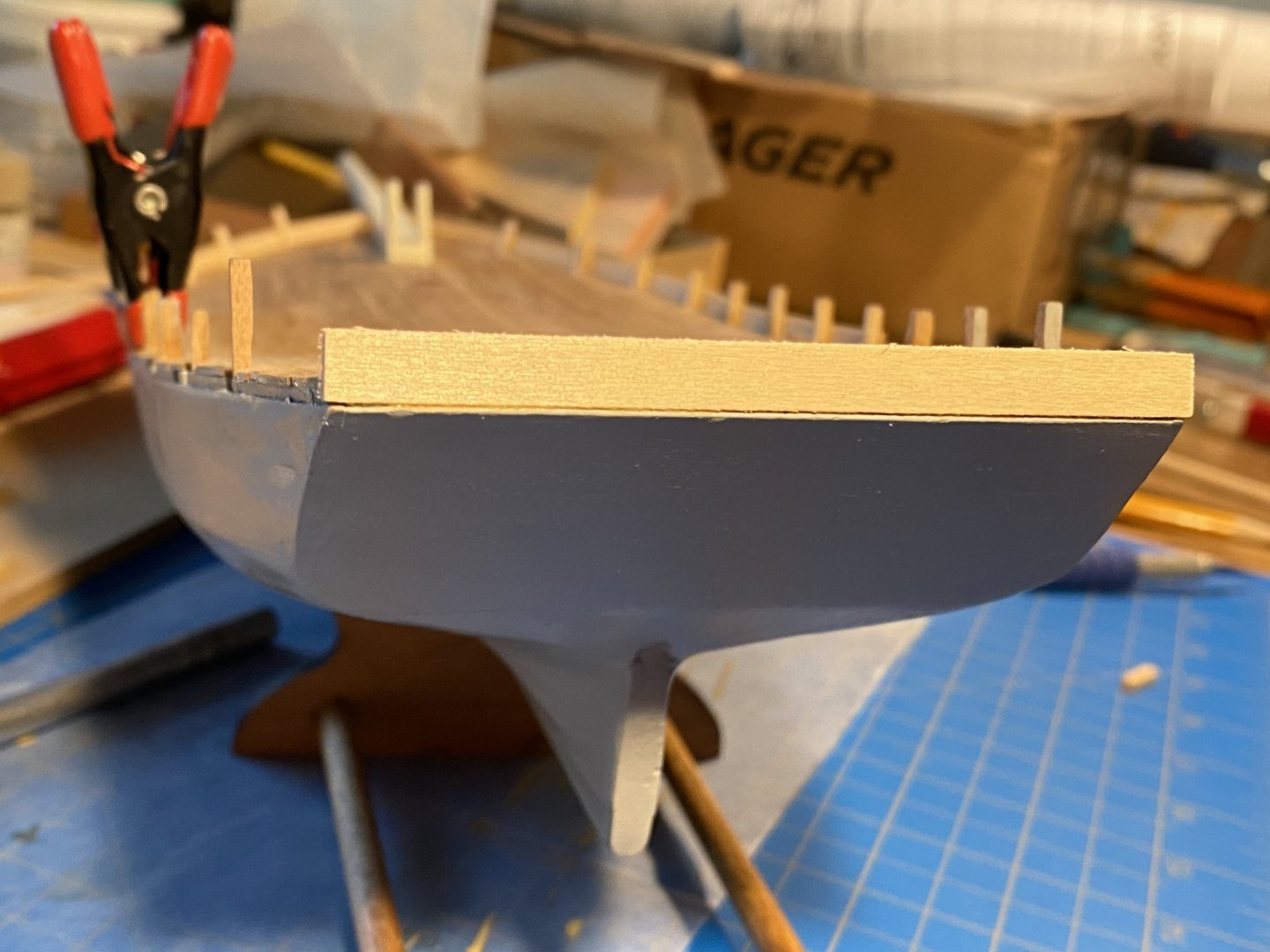
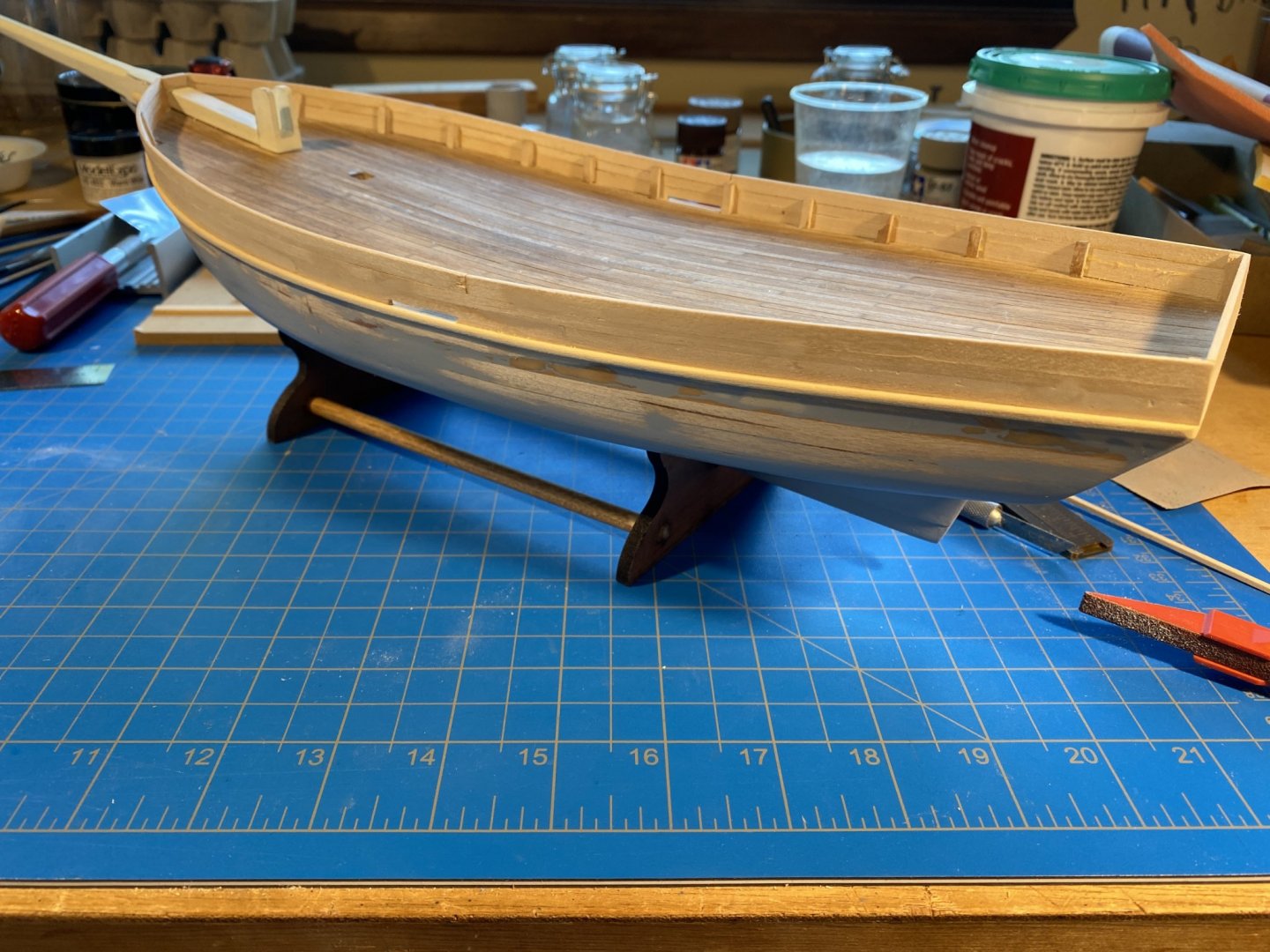
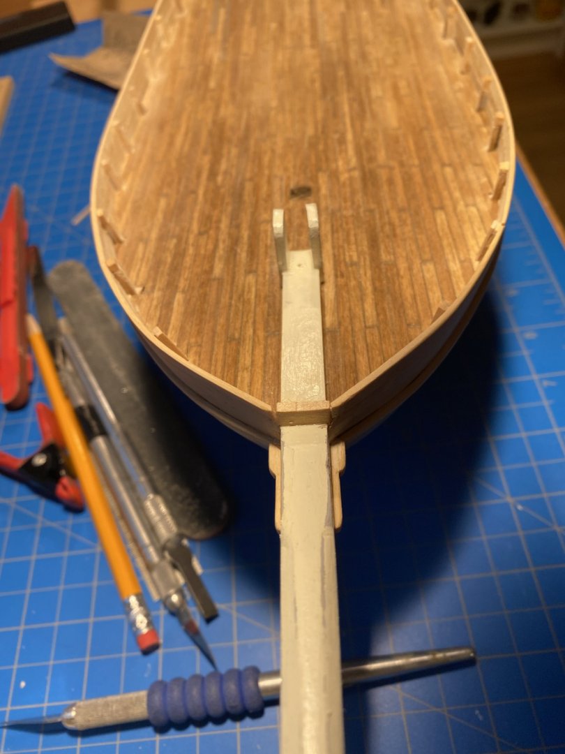
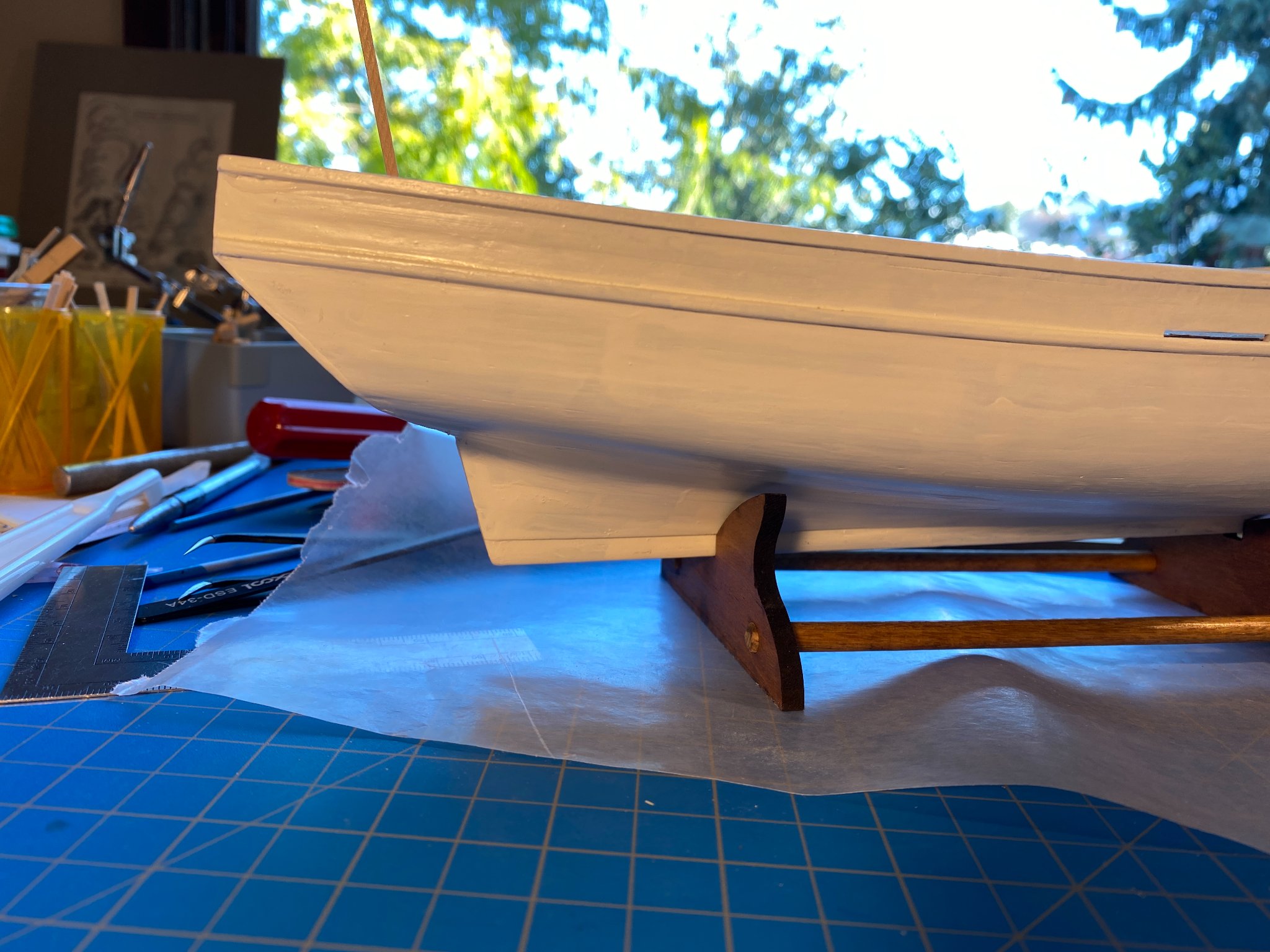
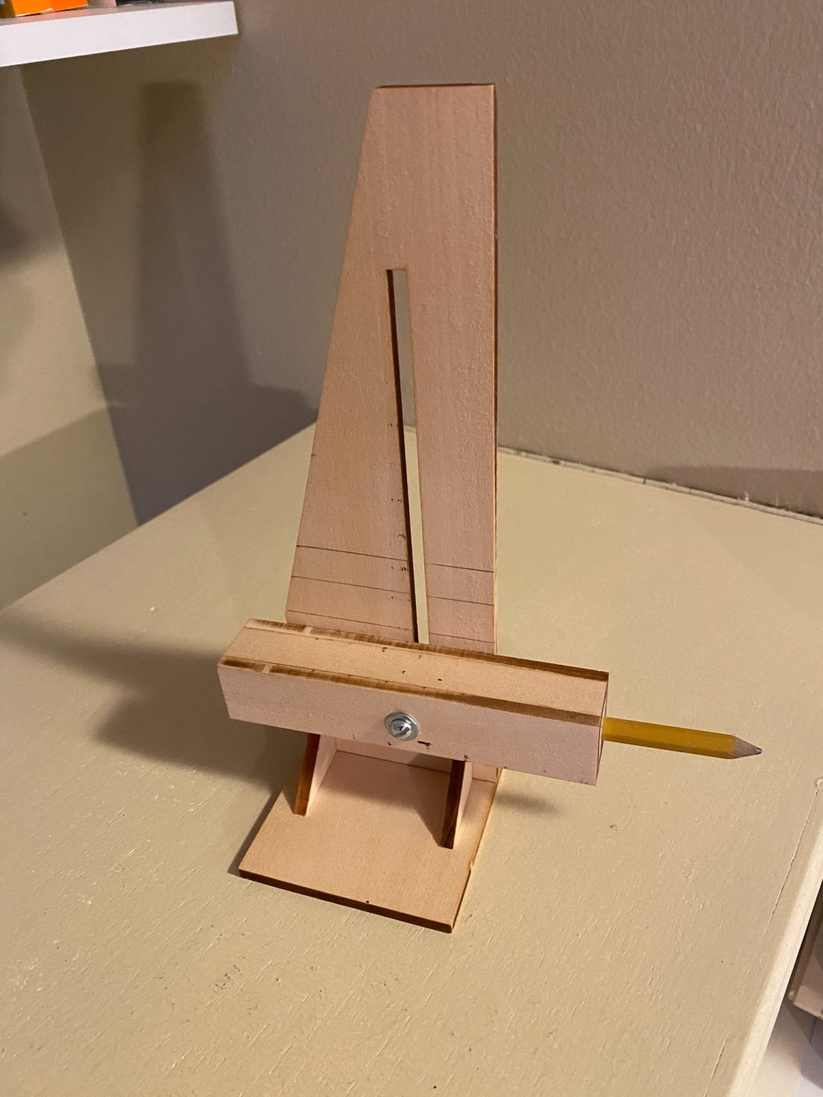
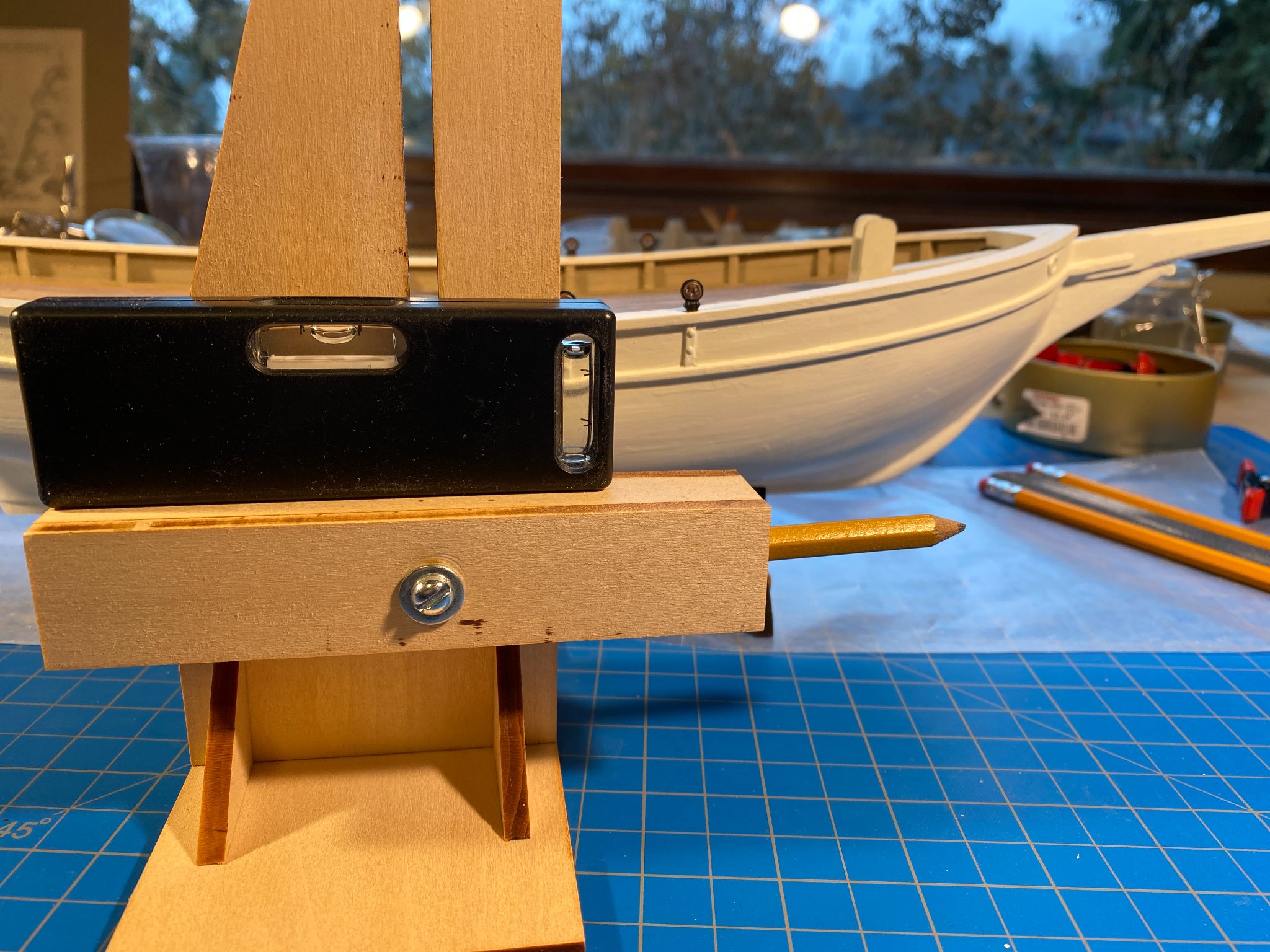
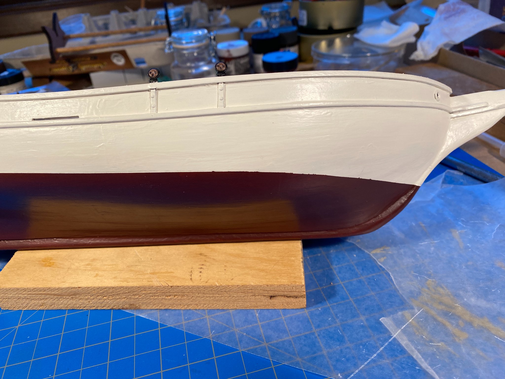
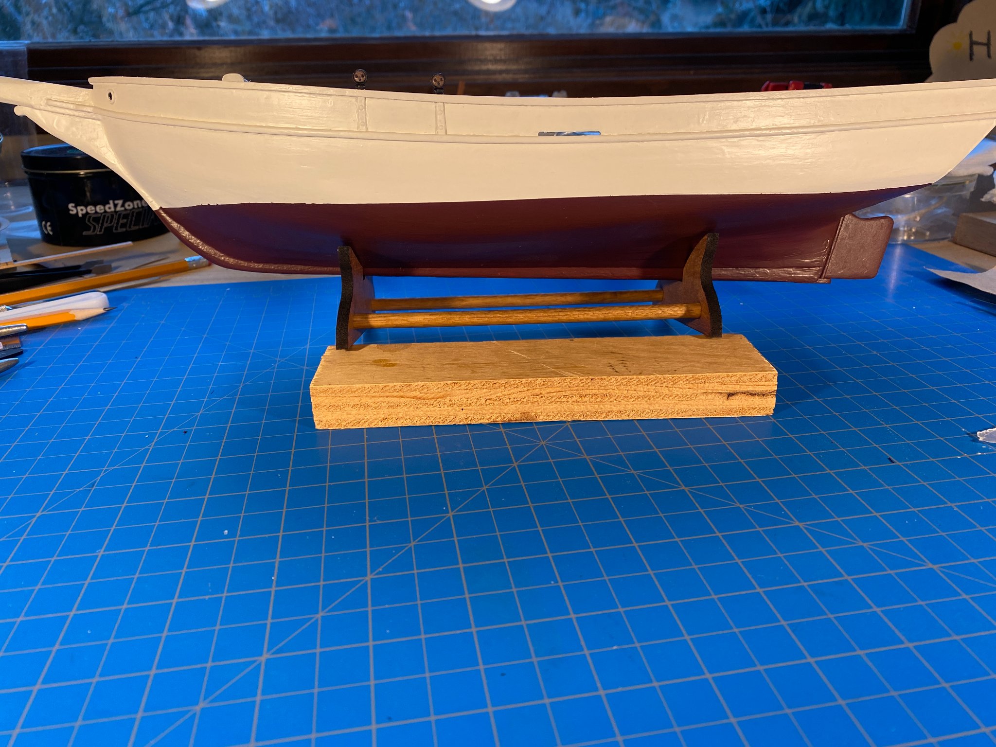
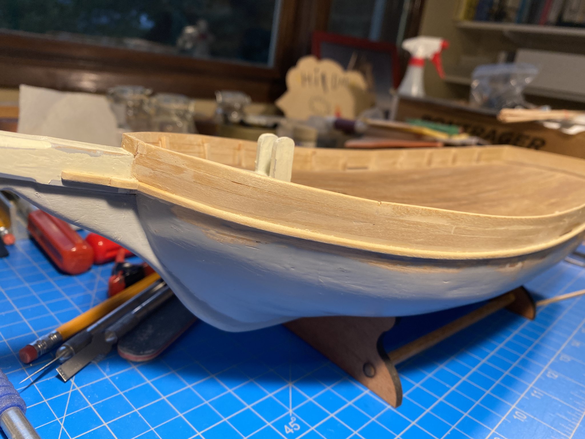
Not many pictures in this post, but yesterday I reached a major milestone--I completed painting the hull. I put something like three coats of white on the entire hull, then followed with another three or four down to a bit below where the waterline would be. Then came masking the waterline. I made photocopies of the plans showing the bow and stern from the side, then cut out templates I could put up against the stem and stern. The waterline having thus been marked at each end, I used the gadget pictured below to connect the dots, so to speak. I must have bought this thing 20 odd years ago, and have now used it a grand total of three times. I have a roll of Tamiya 6mm (1/8th inch) masking tape that worked pretty well following the gently curved part of the waterline. I have some nameless, much older tape that is half that wide, and it handled the sharper curve (where moving forward the bow bends inward toward the stem) quite well . . . until I lifted it off the hull to reposition it, and it pulled a bubble of paint with it. To touch, it feels noticeably stickier than the wider tape, and I decided I had no choice but to not use it. Using three or four pieces of the wider Tamiya tape to make the curve left me concerned that the bend wouldn’t be a smooth one, and I found it all but unavoidable to leave a tiny wrinkle here and there. I had bought some Model Shipways “Hull Copper Red” to use below the water line, a color that I might more accurately describe as “plum purple.” Especially when wet it’s pretty ugly, but dry it does bear some resemblance to anti-fouling paint I’ve seen on many a sailboat. I read somewhere that anti-fouling paint was becoming an alternative to copper toward the end of the 19th century, so I figured this wouldn’t be too far off. This picture is after a couple of coats of the stuff. You can see where I had to use several pieces of the wider masking tape to make the curve. After three or four coats of the stuff, none of the white showed through any more, and it had become a solid consistent color (whatever that color was). So yesterday was the moment of truth, as I very slowly and carefully peeled off the tape. And low and behold, the waterline looked pretty good. There are a few small blemishes, a couple of larger ones that I will try to touch up, and a few more tiny ones that nobody but me (and perhaps others on this forum) will be likely to notice. The starboard side looks a little better. I cut out the laser-cut rudder a month or more ago, slightly tapered the leading edge and more aggressively tapered the rest, glued it to a 3/32” (I think) dowel/rudder post, and more recently gave it a coat or two of the purple plum paint Then after the first or second coat of the same paint on the hull, I used a fine toothed saw to cut a 3/32” deep and maybe ¾” long notch in the aft end of the keel. I then cut a short strip of 3/32” by 3/16” stock, drilled a hole in it to take the bottom of the rudder post, and then glued the whole thing in place. The pictures below were taken later, after the hull and rudder assembly were fully painted. The paint job on the hull right against the rudder looks much better in the first picture, and fortunately in real life, than it does in the second and third pictures. I was somewhat distressed with the bottom of the rudder post hole being noticeably off center, and put some effort into hiding that flaw with wood filler and sanding. Only once I was satisfied with the resulting camouflage did it dawn on me that the bottom of the keel is something no one will ever see once the boat is complete and affixed to its stand. I guess such is the compulsion of a ship model builder. Next up . . . affix that stand to the hull, or at least drill some holes in the keel for that purpose. Then get some deck furniture on board, followed by spars, sails and rigging. That pin prick of light at the end of the tunnel is indeed getting larger. ☺️


- 82 replies
-
- 4
-
-
- spray
- BlueJacket Shipcrafters
- (and 1 more)
-
And I should have added that, yes, quite a few sessions of filling, sanding, filling again, sanding again . . .
-
Thanks Josh. I used to use Bondo, which someone on one of these forums recommended years ago. It is actually an auto body finish product, but it works very well in this context too. However, it has really noxious fumes (my wife would be downstairs and at the other end of the house and would complain when I used it). More recently I've used Elmer's WoodFiller, which works very well too, without the fumes. I picked that up at Ace Hardware.
-
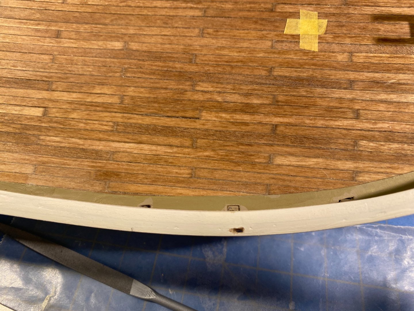
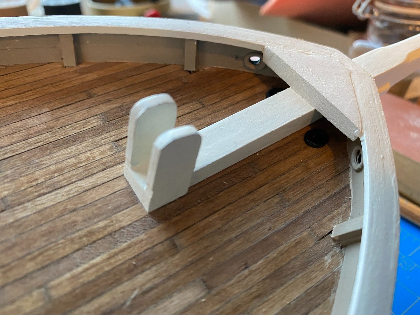
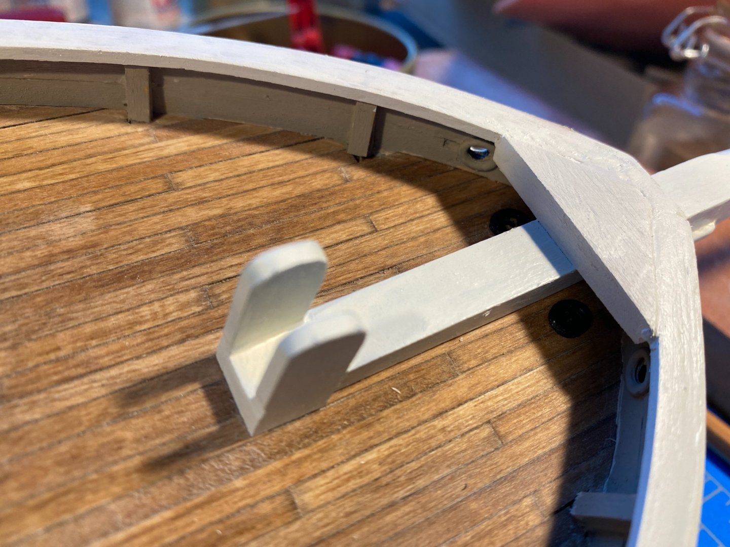
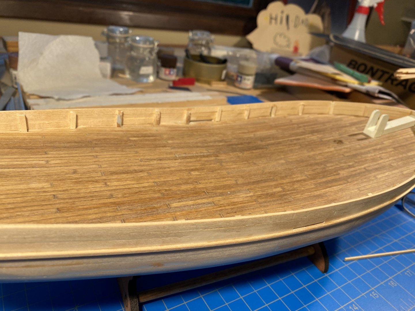
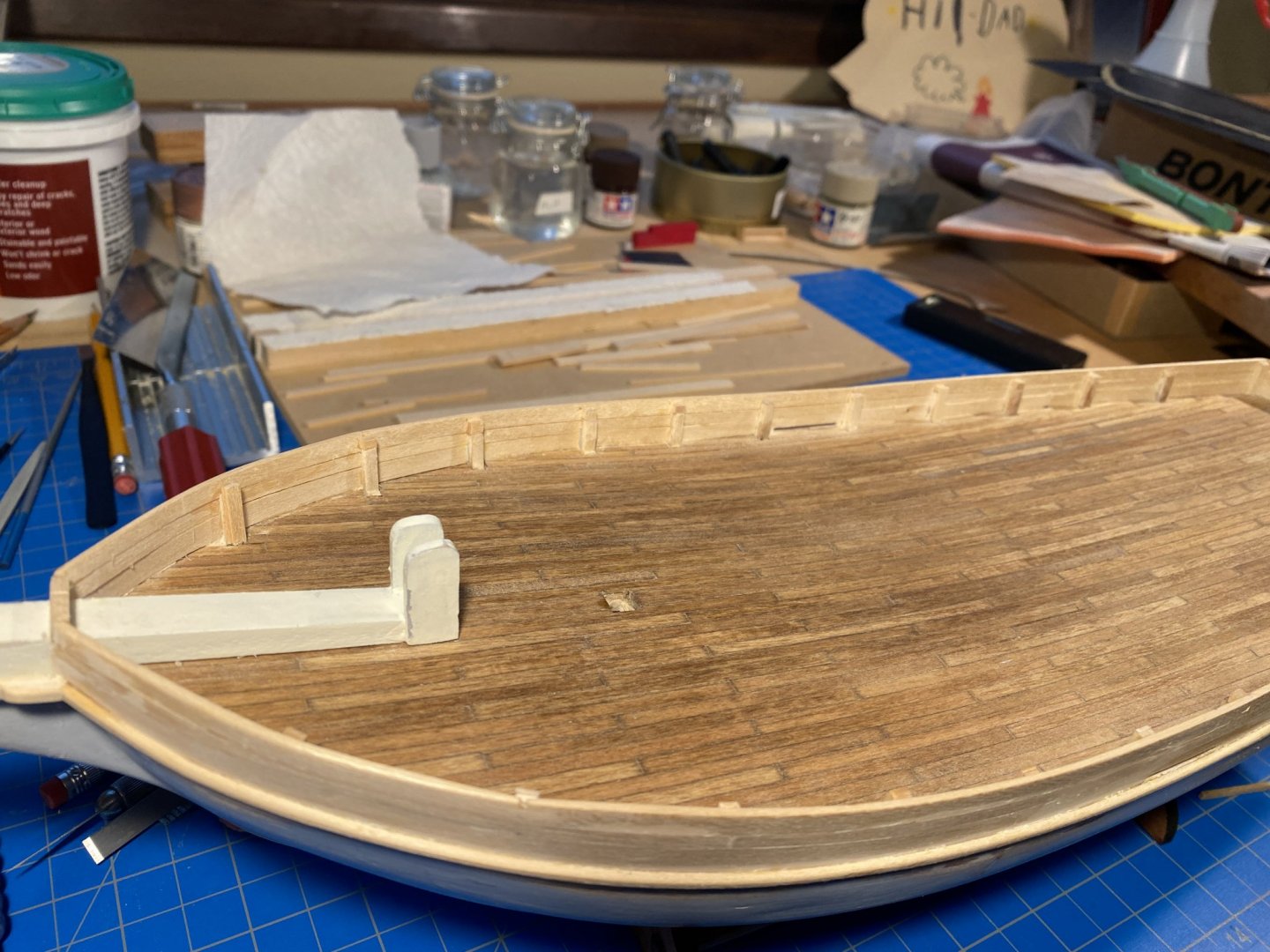
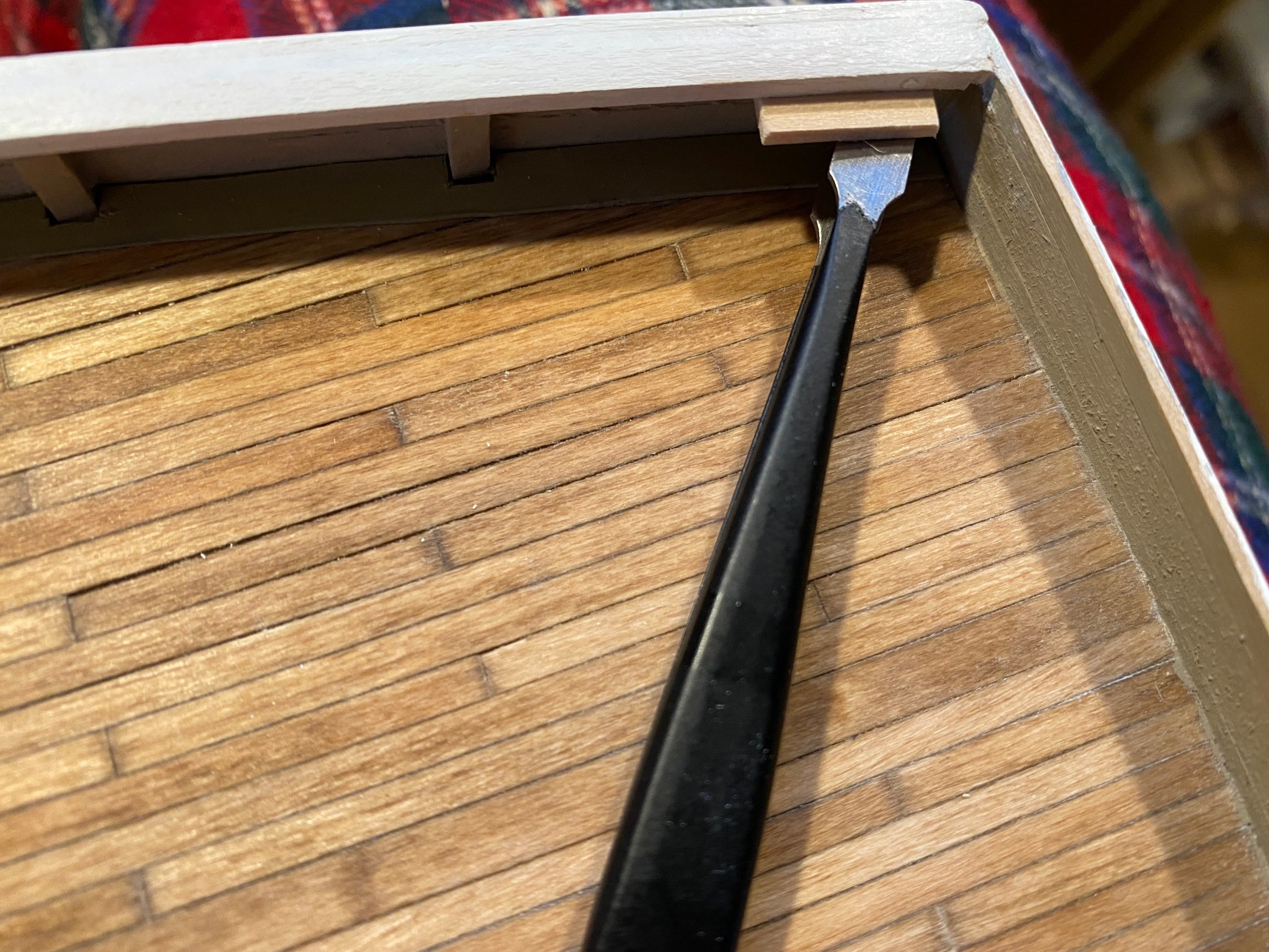
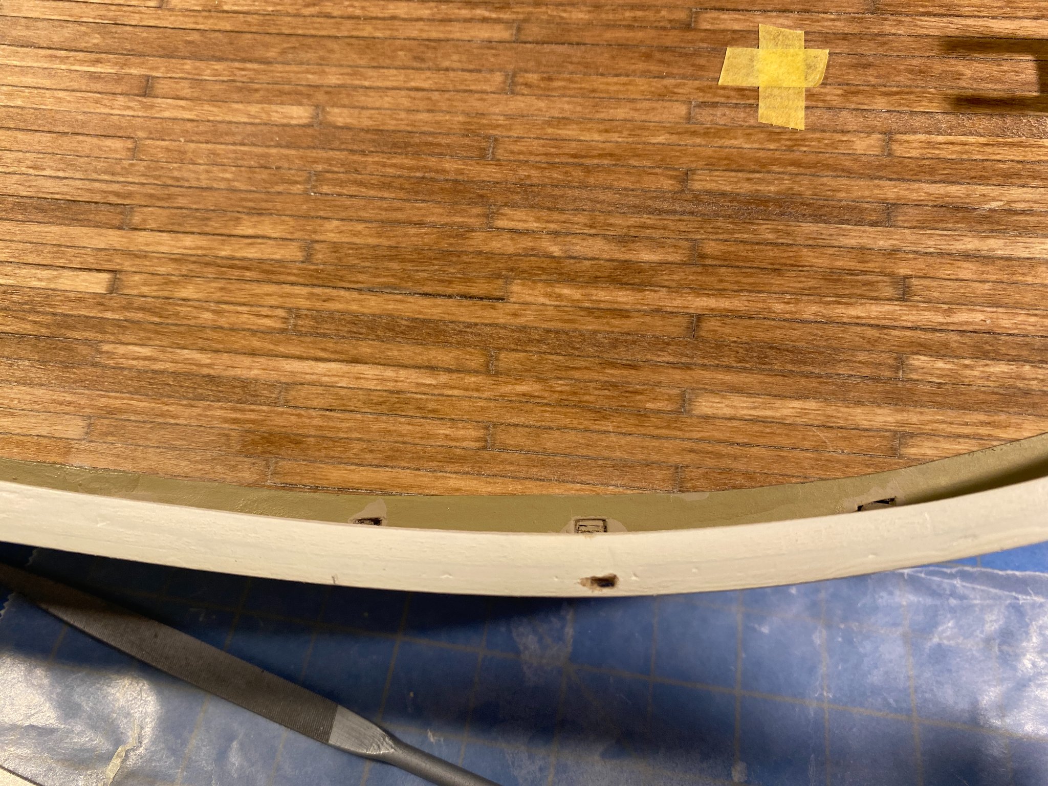
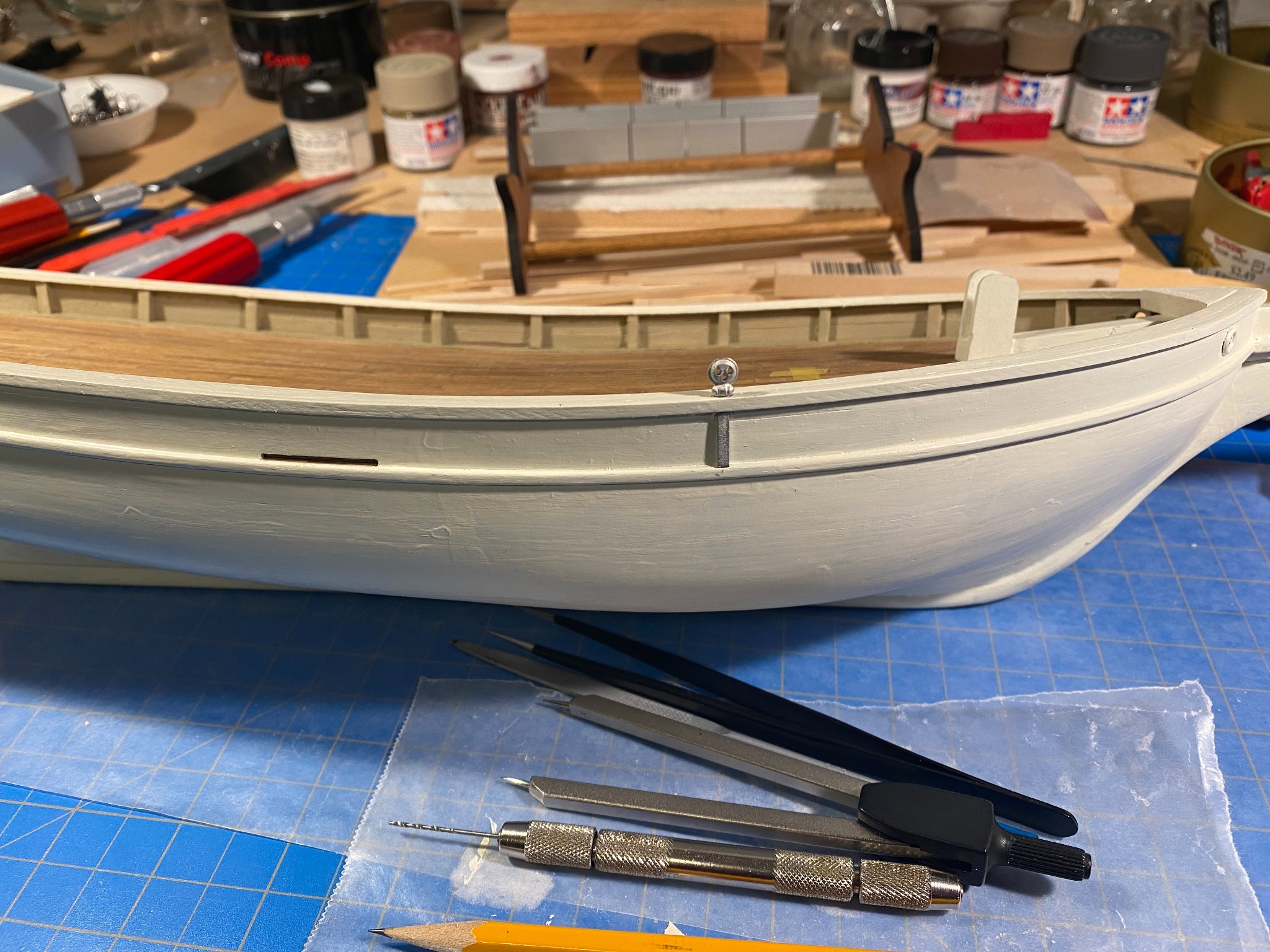
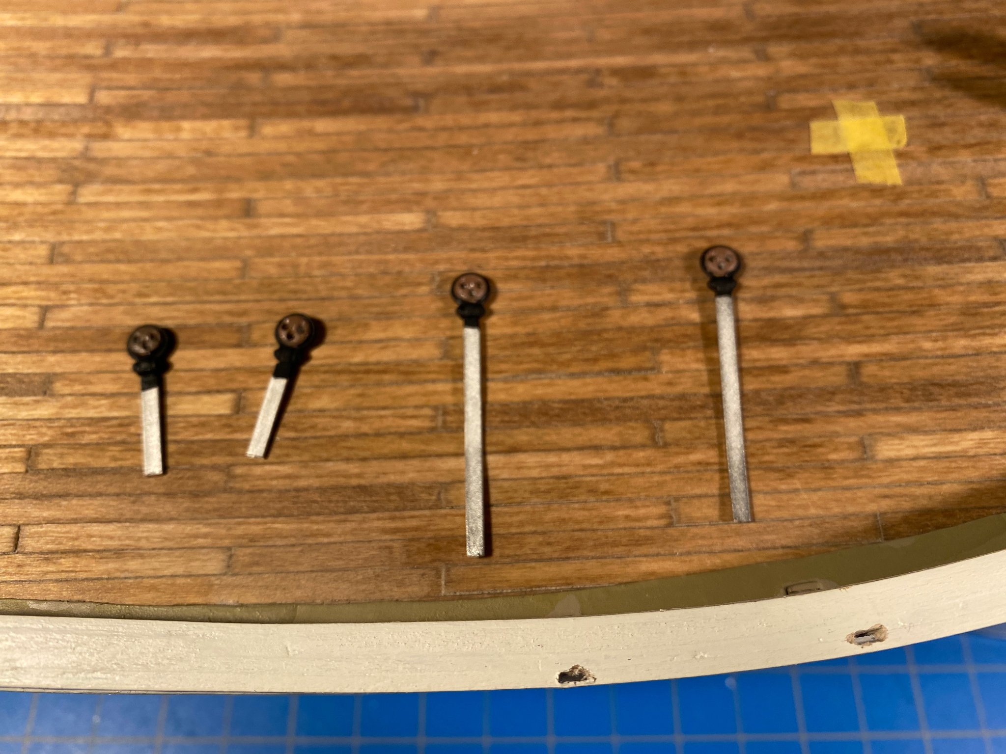
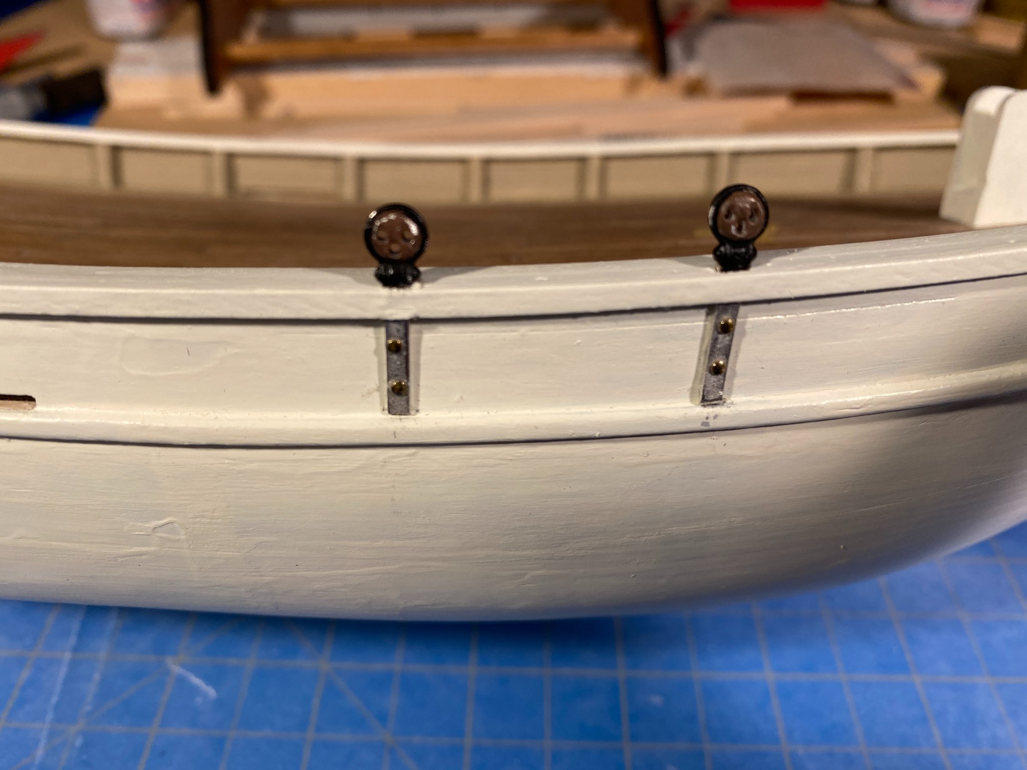
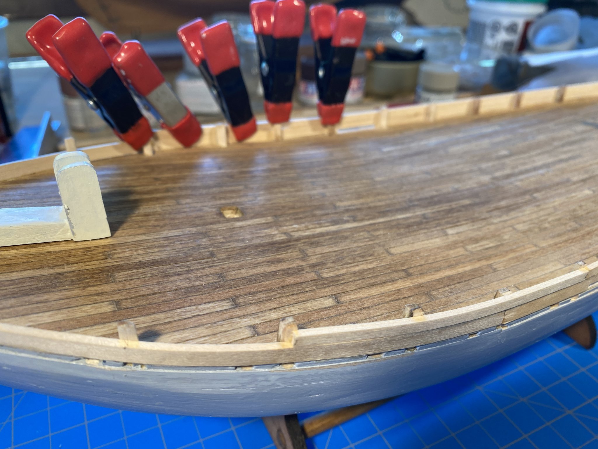
A new, interesting challenge. I happened to notice while staring at the plans (something I find myself doing quite often) that the chainplates run against the hull underneath the rub rail and the cap rail. My immediate thought was “Oh [expletive deleted], I should have cut notches in those two rails before gluing them to the side of the hull.” But as I thought more about it, I wondered how difficult it might be to cut the notches exactly where needed in a boat-length strip of wood before it was attached to the hull, and would the notches weaken the strip where it needs to bend when glued to the hull? It would be just my luck to have a strip break as I am as I am bending the lengthy strip to the hull with a coat of drying glue on it. All academic of course since now I have no choice but to cut the notches after the rails are glued to the hull. So very carefully, timidly perhaps, I drilled a couple of very small holes in the caprail marking the ends of the first notch. Then I put a new blade in one of my X-Acto knives and gingerly connected the dots so to speak. Amazingly the end result was a notch I could slide the Britannia chainplate through. Now with a little too much confidence I made the second notch. As can be seen in the second photo below, the holes weren't drilled as close to the hull as they should have been, with the result that at the bottom of the notch there wasn’t much more than paint separating the notch from fresh air. The final two notches were done with a little more care. Next was the rub rail. After staring at it from all angles, I decided that would be pressing my luck. It undoubtedly could be done by drilling the starter holes from below, but we all know drilled exit holes don’t always appear exactly where planned. So I cut the chainplates at the top of the rub rail and figured no one looking at the finished product would ever know the difference. As can be seen above, the kit supplied fitting is a single piece, Britannia chainplate and deadeye together, and of course a Brittania colored deadeye just wouldn’t do. I decided I would paint the deadeyes the Flat Earth color discussed in a prior post, and paint the surrounding metal above the caprail black. Below the caprail the chainplate would be painted white to match the hull. In the photo below you can also see the notch I cut a little farther away from the hull than I should have. I found that I had some tiny nails that I could use to simulate bolt heads, so I drilled a couple of holes in each chainplate to put the nails through. I then put some glue on the back of the chainplates, slid them through their notches, and pressed them against the side of the hull for a minute or so while the glue dried. Then I grabbed the drill again and carefully drilled into the hull. The chainplates are placed outside two stanchions, so there was some depth to drill into. The first two times I did this, it dislodged the glued chainplate from the hull (in my impatience I probably didn’t let the glue dry long enough), so I had to hold the deadeye pretty tightly to hold the whole thing in place while drilling. Some of the paint rubbed off making my very careful paint job look pretty sloppy (but easily enough remedied). Oddly in the picture below, the chainplates don’t look as parallel as they really are. Another coat of paint on the upper half of the hull, and the whole thing is beginning to look pretty good. Daylight savings time just ended, and being a morning person, it's nice to look out the window when I get up and see some light. ☀️ 😎


.thumb.jpg.e4bcbe6a02d7a6d61f606644b74823ba.jpg)
- 82 replies
-
- 5
-
-
- spray
- BlueJacket Shipcrafters
- (and 1 more)
-
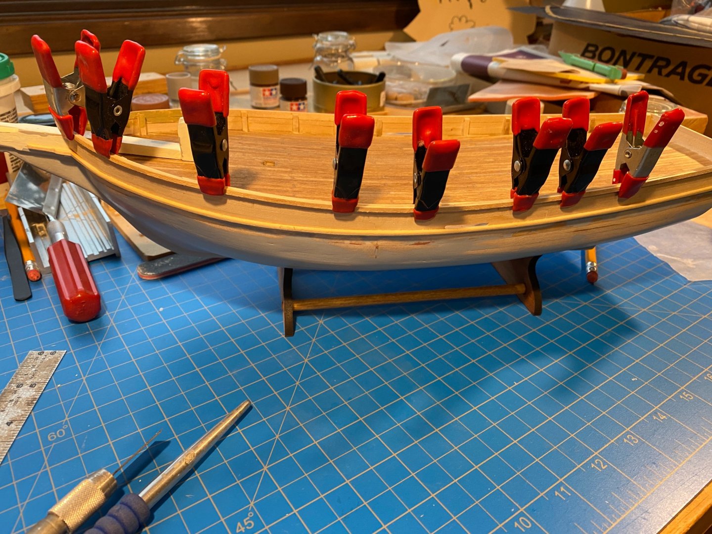
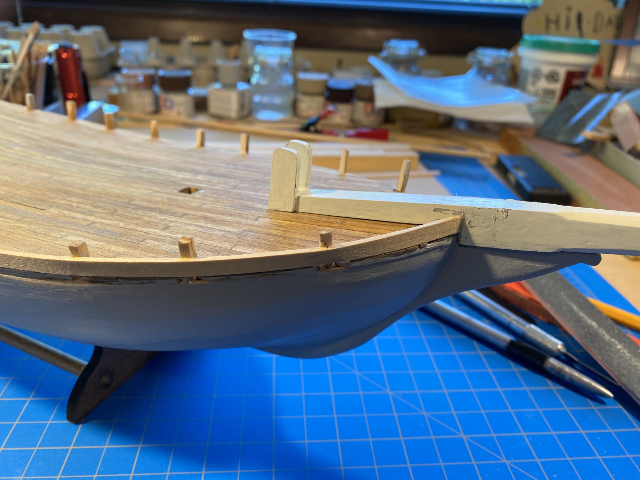
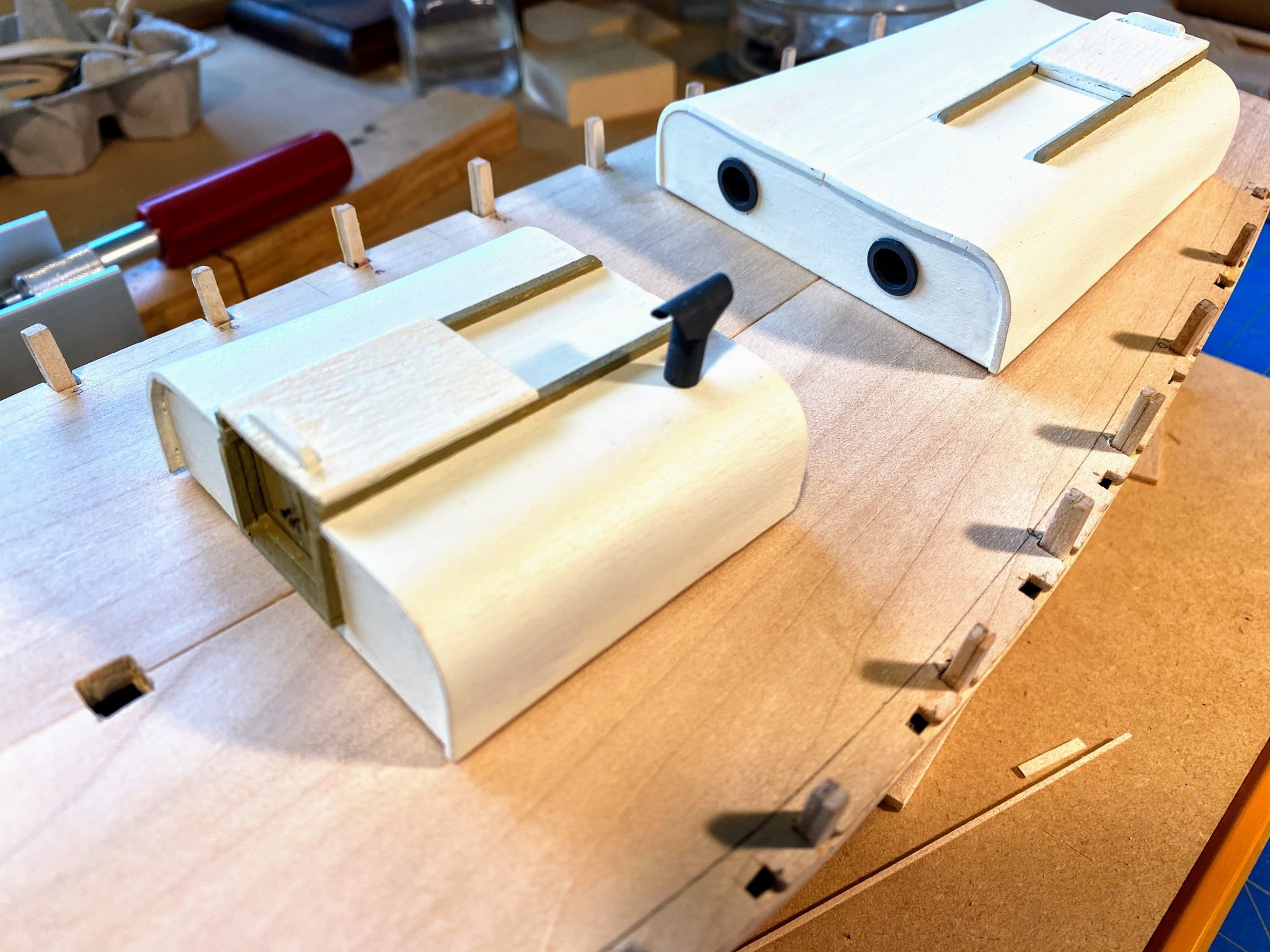
So I left off having glued the rubrails in place, and giving some thought to the caprails. The outer caprails were pretty straightforward. . . . 1/16th by 3/32nd strips laid and glued against the hull. I chose to make them from a single strip, so that they would hopefully make a nice graceful curve matching the rub rails and the sheer line. Next I painted the inside of the bulwarks with Tamiya “Buff”, same color as the yet-to-be-installed waterways and the trim on the cabins. Before that I used a little wood filler on the bigger cracks in the bulwarks, but found sanding that area (inside of a concave curve) was a little more difficult than I anticipated. The next strip of the rail cap was another 1/16th by 3/32nd strip, but this time lying horizontal, on top of the stanchions. This also required some creative use of the iron and clamping, so that the horizontal strip didn’t flip vertical. Somehow it all worked. Here I did not use one continuous full length strip, but three shorter ones. You can see the painted inside of the bulwarks in these photos. Last came the inner rail, a single vertical 1/16th by 3/32nd strip. Sometimes difficult at the bow, but somehow I got it done. The tops of the completed rails definitely needed some filling and sanding, but that’s to be expected. What happened next was not expected. Before I installed the rubrails, I painted the hull below the sheerline with a couple of coats of a Tamiya primer. It went on well, was pretty easy to apply, but the fumes were nauseating. Fortunately I got it done outdoors before the weather turned (a cold spell this past weekend had highs below freezing). What I have learned more recently (elsewhere in these boards) is that you don’t want to use an oil-based base layer and then cover it with water-based acrylic. I did exactly that, painting an off-white from Model Shipways called “Warm White” over the primer. True white, like you’d find on many of today’s fiberglass yachts, just seemed too pristine for something Joshua Slocumb sailed around the world. No issues with the color choice. But when I tried to give the first coat a light sanding, instead of the dust I expected, the white came off in chips and strips. It did not adhere well to the primer coat at all. I sanded and scraped most of the first layer of white paint off. In the photo below, you can see that I also painted the outside of the bulwarks white, without first using the primer, and it went on and stayed on just fine. I then did some experimenting painting scrap sheets of wood. What seemed to work was several coats of the acrylic, with no sanding in between. That meant I had to be sure to keep paint drips from drying. The jury is still out, but I think this is working. The finished product probably won’t be as smooth as I would like, but I can always rationalize that Slocumb’s Spray probably wasn’t all that smooth either. Next I drilled the hawse holes in the forward bulwarks and the deck. Always makes me a bit nervous to drill anything more than the tiniest hole through a completed surface. Sure enough, I knocked a chip of wood out inside and aft of the port hole in the bulwarks. I should have tried to hold a block of wood against the inside as I drilled, which would have been easier if I had drilled the holes before putting the caprails on. Live and learn. Paint will somewhat disguise the flaw. In the process of gluing on the Brittania metal hawse hole lips, I dropped one, perilously close to the mast hole. The thought of trying to get it (or any other small fitting) out of the hull had it actually fell in the hole would be enough to keep me up at night. To prevent self-induced insomnia, I taped over the hole, as can be seen in the photos. I made what the plans refer to as the “bow block” out of three 3/16th square strips glued side by side. I cut the glued-together block roughly to the desired shape, then sanded to fit. 3/16th was a little too thick at the bow, so I tapered the whole thing a bit to lie appropriately on top of the bowsprit. Final project for this posting was the glue in the painted, construction paper waterways I so carefully cut out quite a few weeks ago. I debated whether to cut each one into three (or more?) sections, but after a couple of glueless practice runs, I decided I could do it safely with a single boat length piece. A used thinly applied wood glue (Gorilla brand), which gets tacky pretty quickly but takes a little while to truly set up. A bit stressful at times, but it all went in pretty well. I think painting the hull, including installing the rudder, is next.


- 82 replies
-
- 6
-
-
- spray
- BlueJacket Shipcrafters
- (and 1 more)
-
Really enjoying your posts Josh, and great work! You're at a point where you are passing me, and moving at a much faster pace. Now I get to learn from your challenges and good work. I finished the cap rail, got a few coats of paint on the rails and hull, and this morning I glued in the waterways (or margin planks). I will do another post within the next week or so. Your blog is in the correct forum--1850 to 1900. When they changed the forums around, mine got put incorrectly into post 1900 for some reason. Incidentally, my mask rake seems to have worked out correctly when locating the hole as shown in the plans. The rake is definitely forward relative to the deck (which slopes upward at that point), but it is slightly aft relative to the waterline. Looking forward to more of your posts.
- 70 replies
-
- 2
-
-
- Spray
- bluejacket shipcrafters
- (and 1 more)
-
I'm learning that if I drag a photo to the "Drag files here to attached" area below, and then don't use it in my post, it gets added at the end anyway. Or at least that's what I think happens and explains the random photo at the end.
-
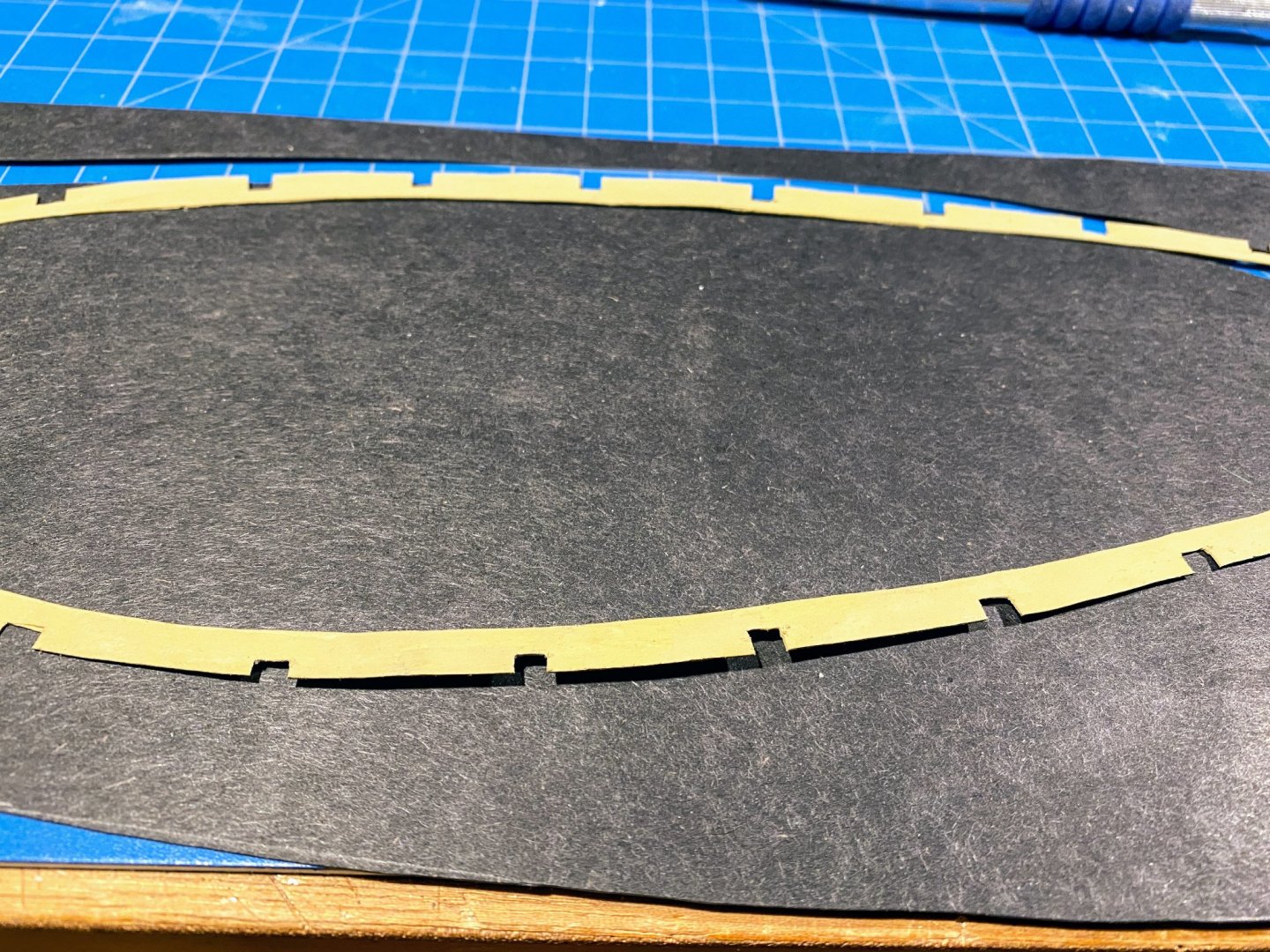
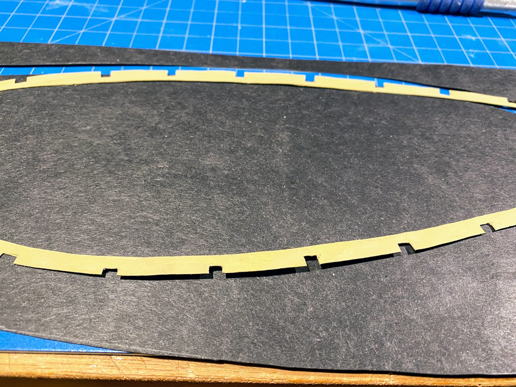
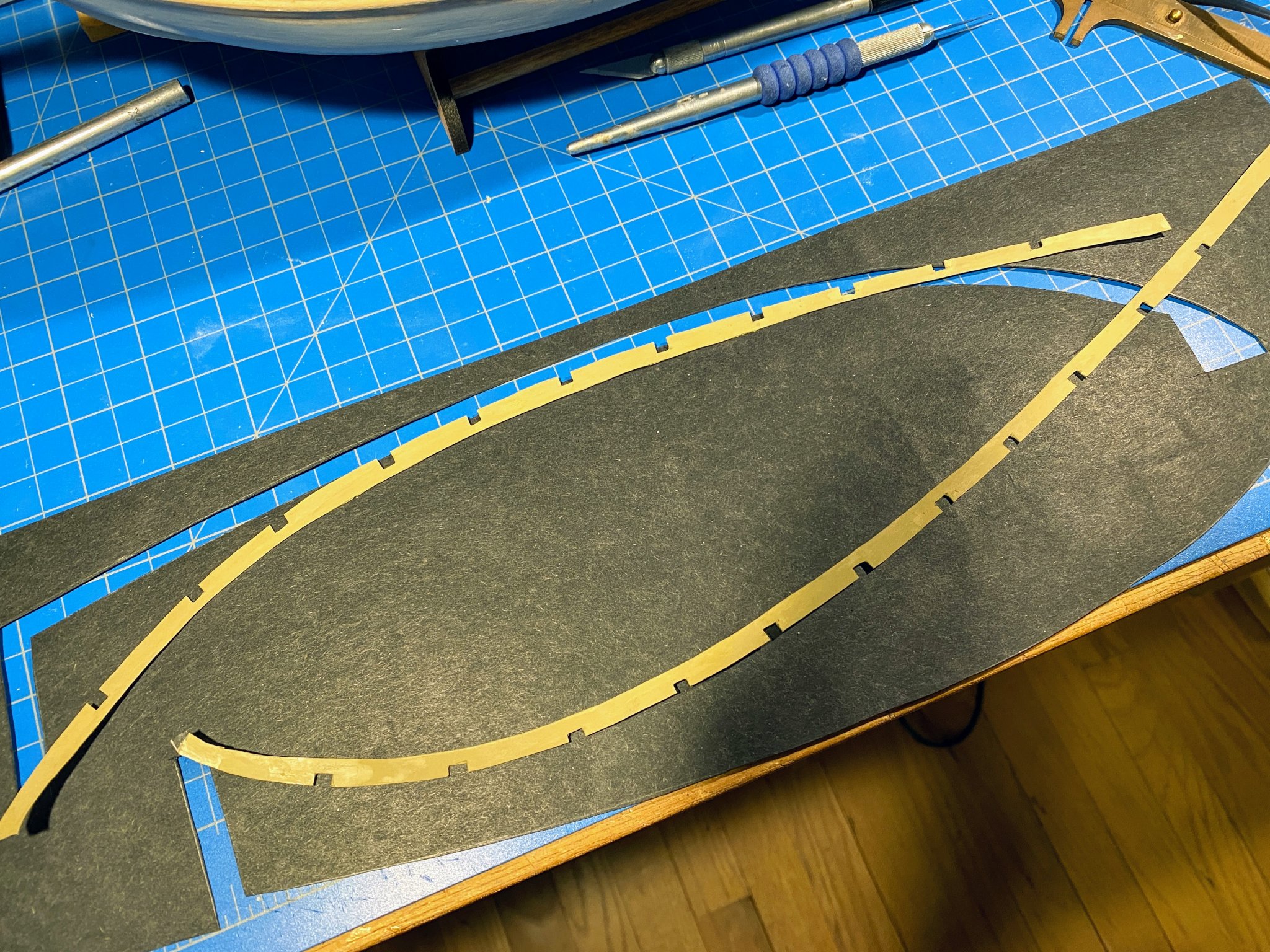
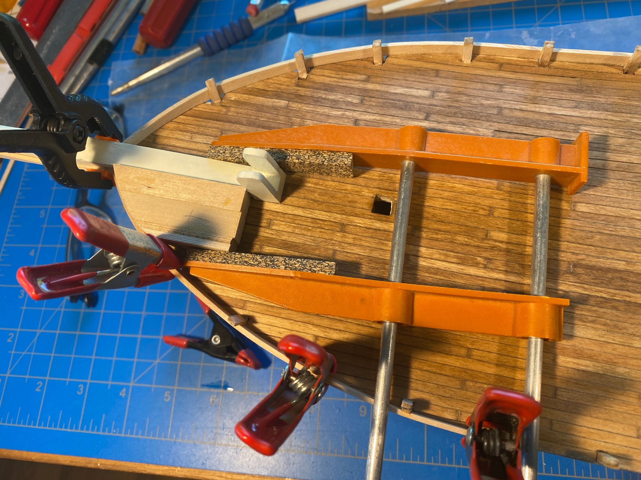
In my prior post I mentioned creating margin planks (or waterways) which would lie on top of the deck planking, not adjoining it. Basically I was too lazy to try to make the edge of the deck planking precisely meet the edge of the margin plank. In retrospect that may not have been a great decision, but it is what it is. The kit-supplied laser cut pieces would be too thick and too obviously lying on top of the deck. The instructions say they are to be painted along with the inside of the bulwarks (I’m wondering a bit why), and I felt they had to be thick enough to absorb the paint without wrinkling. After looking at a few alternatives, I settled on some construction paper (that happened to be black). I cut them out with an X-acto knife, then used some small sharp scissors (usually used for cutting rigging line) to cut the insets for the stanchions. Then they were painted the same Buff color I used on the cabin trim. They will be installed later. Next was bevelling the stanchions to accept the bulwarks planking, which involved a bit more work than I anticipated. A lot of wood was removed in some places, shims added in others, etc. No pictures of this task. I also realized that if the bulwarks are to be a consistent ½ inch above the shear line as shown on the plans, then most of the stanchions were a little short, and they certainly weren’t consistent in height. That I would deal with another day. Nothing very exciting about planking the bulwarks. As I started to do midway through planking the rest of the hull, I used Chuck Passaro’s recommended method of wetting but not soaking the planks, then using an iron to bend the wood around the stanchions. The iron I’ve been using is left over from applying Monocoat to R/C gliders I built another lifetime ago. At the bow there isn’t anything to bend the planks around, so I built a block to serve that purpose. Holding everything in place sometimes required some creative clamping. I made the transom bulwarks by first gluing the first plank onto the hull and deck, then adding the stanchions at each corner, then adding the remaining planks. Along the way I started building the steering apparatus, none of which has been glued together or painted yet. Also below, transom planking further along than above. What followed of course was a great deal of wood filler and sanding. Here are a few "before" photos; "after" photos are further below. Next came the rubrails. The plans show them to be 1/16th of an inch from top to bottom, and the inventory shows 1/16 x 3/32 strips to build them with. I took a couple of those strips, rounded the sharp corners, and glued the 1/16th edge to the hull. I also used a single strip for each one, wanting to avoid any sharp bends where two strips join. The rubrails run part way out onto the sides of the bowsprit, and I made those parts with two short 1/16 x 3/32 strips glued side by side. All in all the process went pretty well. At this point I made some decisions about the caprails. The deck plan shows them to be 1/4 inch wide, which looks about right. But a cross section of the hull shows them to be quite a bit wider -- 3/32 strip outside the bulwark, 3/32 width of the bulwark plank, 1/8 stanchion, and another 3/32 strip inside the stanchions, for a total of 13/32 (or easier for my mind to grasp, a gnats eye wider than 3/8). That just seems too wide. As mentioned earlier, I used 1/16 for planking, and the part of the rubrail outside the planking could also be 1/16. Most of the stanchions were thinner (after beveling) than the 1/8 square they started with, and a 3/32 stanchion seems like a good width. And the inner plank might even be 1/32 (left over from planking the deck). Moving outward in, that’s 2/32 + 2/32 + 3/32 + 1/32, for a total of 8/32, or 1/4 as shown on the deck plan. I think that will look better. Having made that decision, I added shims to some stanchions, shaved some stanchions, and added tiny caps to most so that they are all a consistent thickness and height. The photos below were taken when I was close to finished with that task. As I write this I'm ready to start installing the cap rails. But first I think I will glue the waterways in place, then paint the inside of the bulwarks.


- 82 replies
-
- 3
-
-
- spray
- BlueJacket Shipcrafters
- (and 1 more)
-
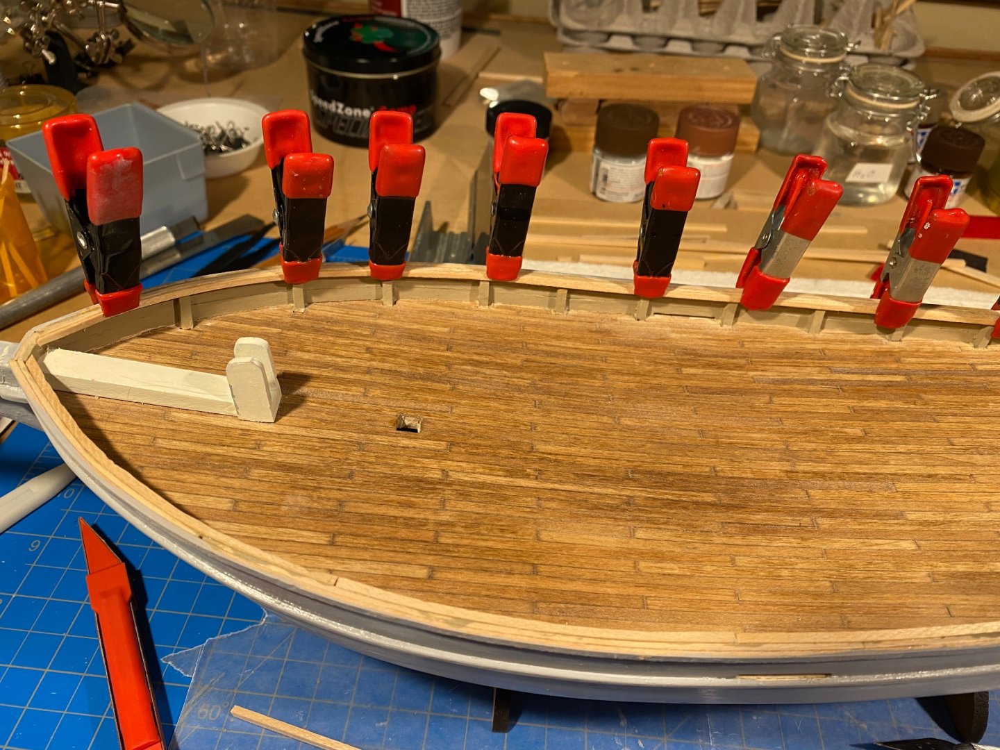
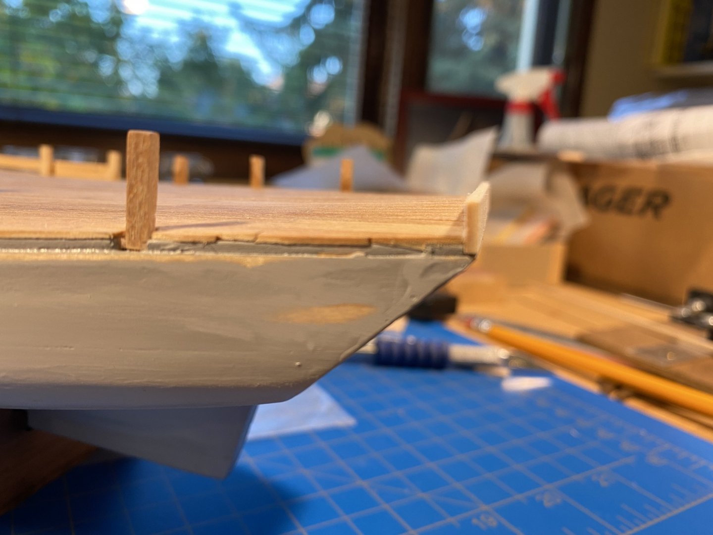
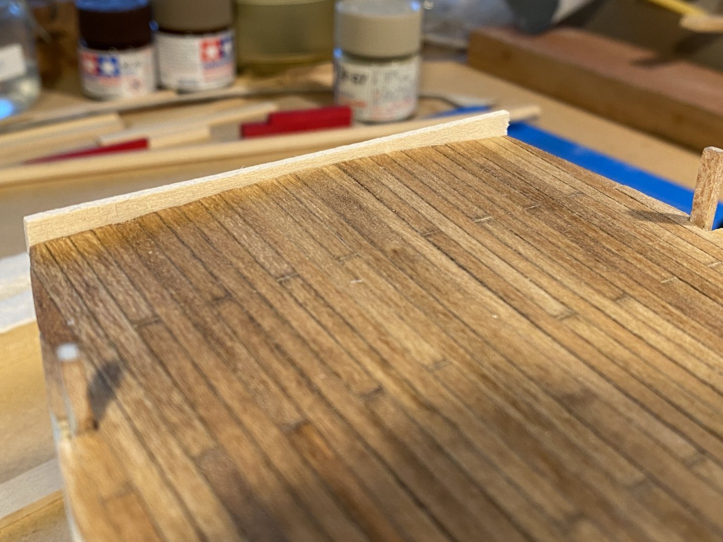
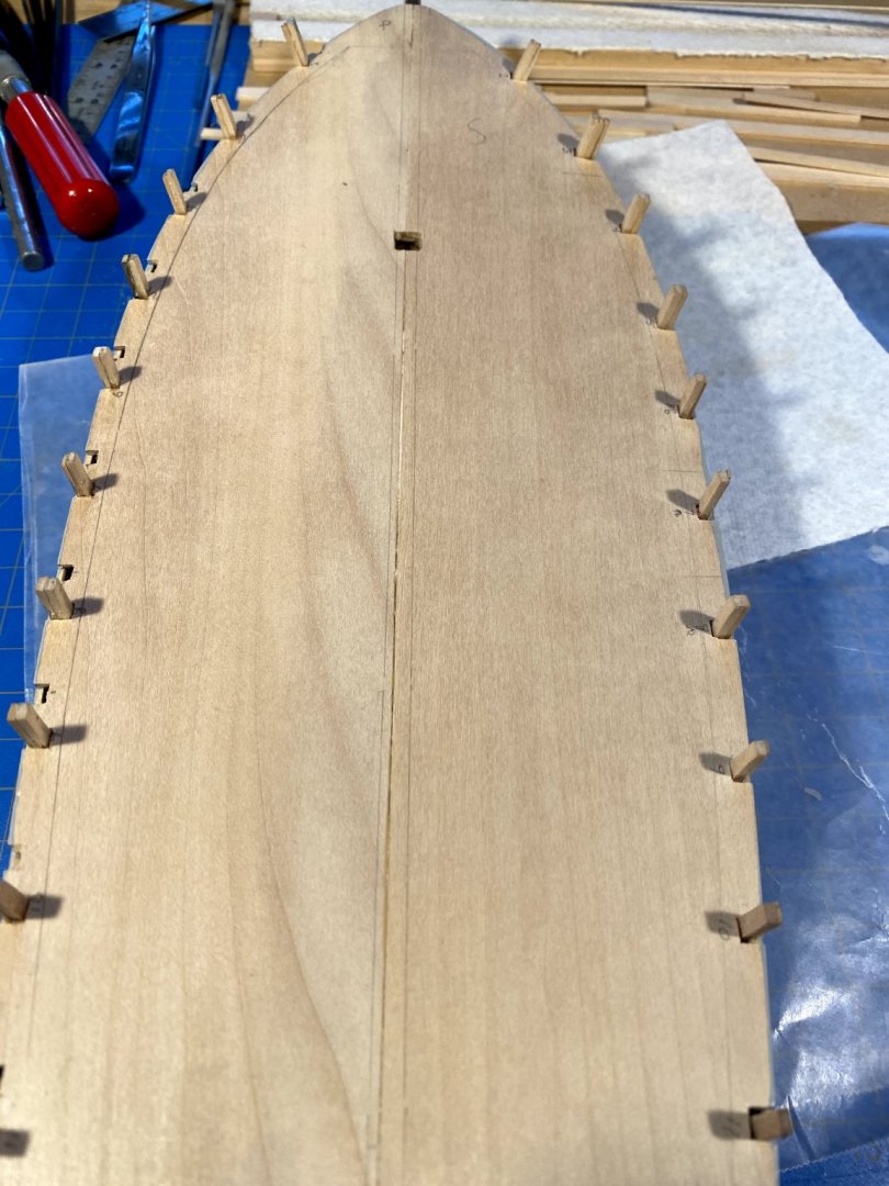
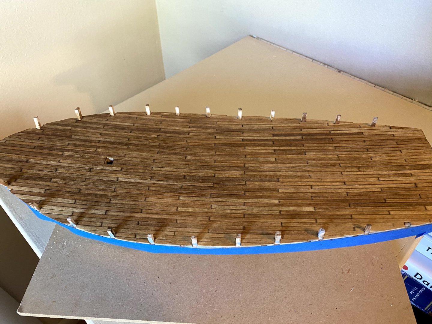
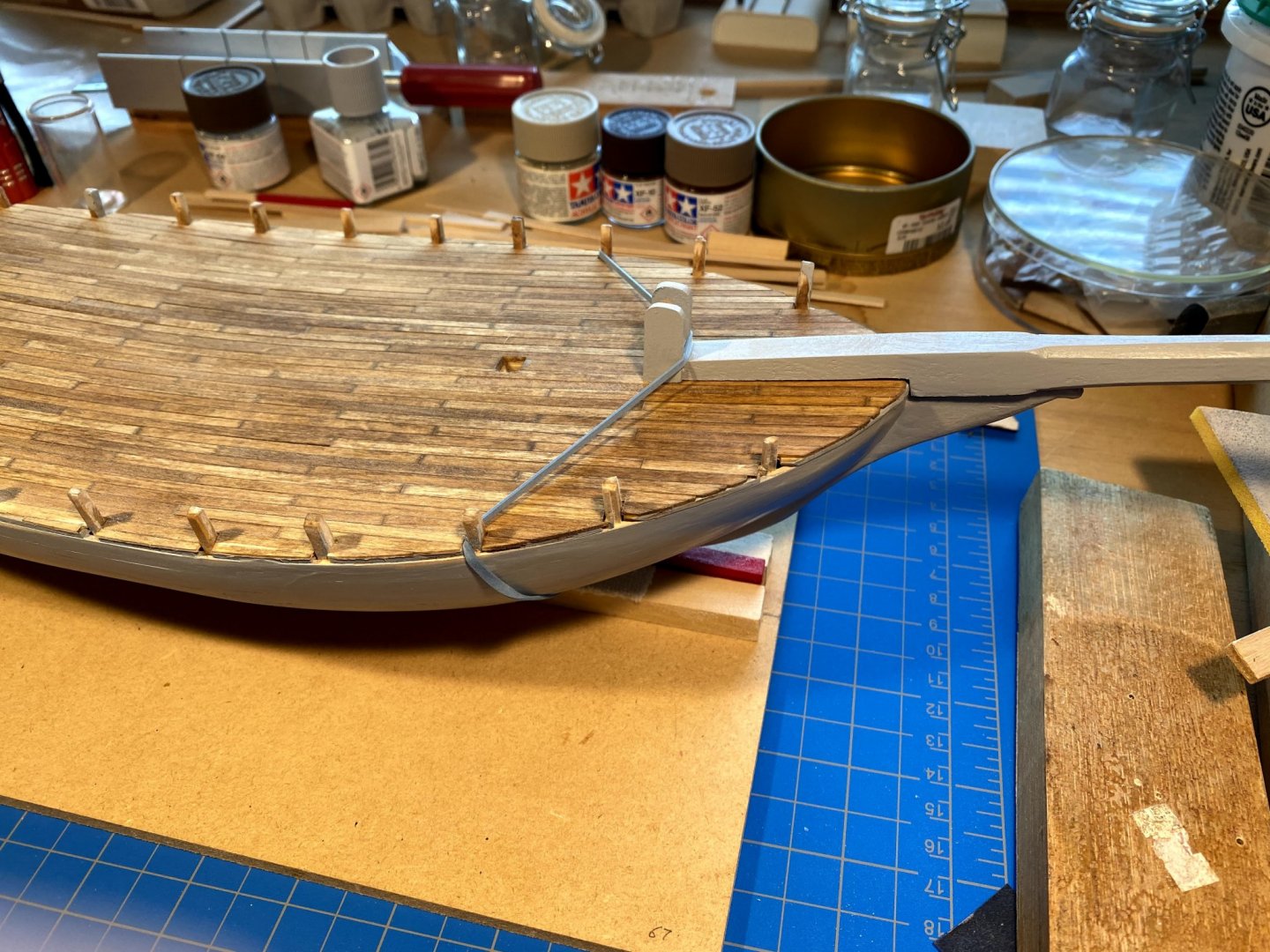
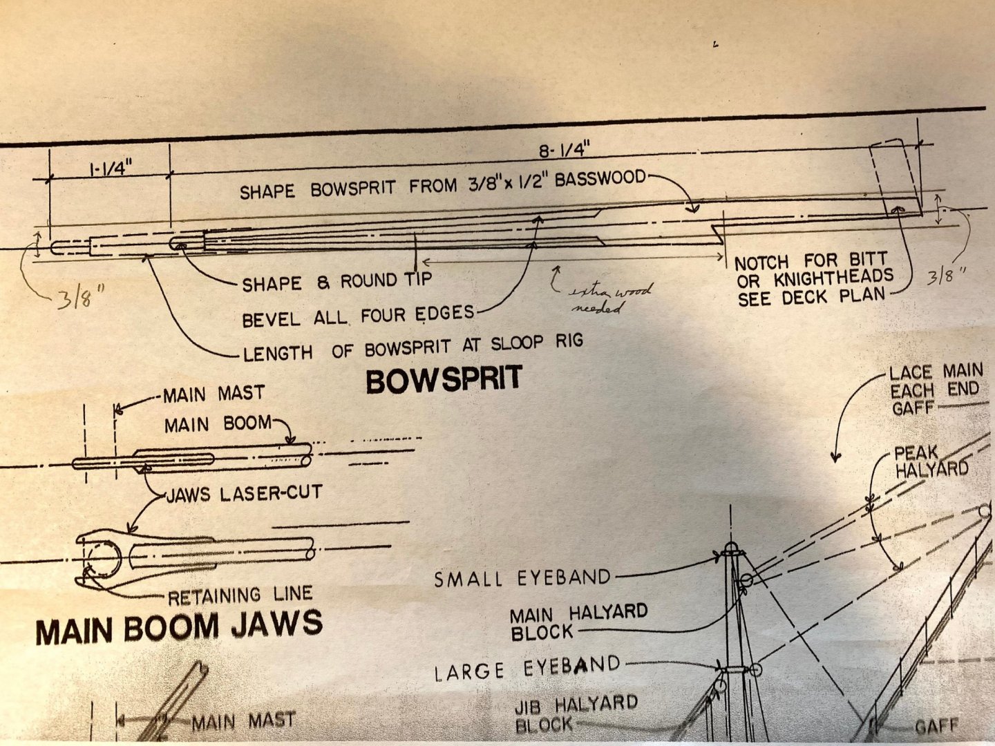
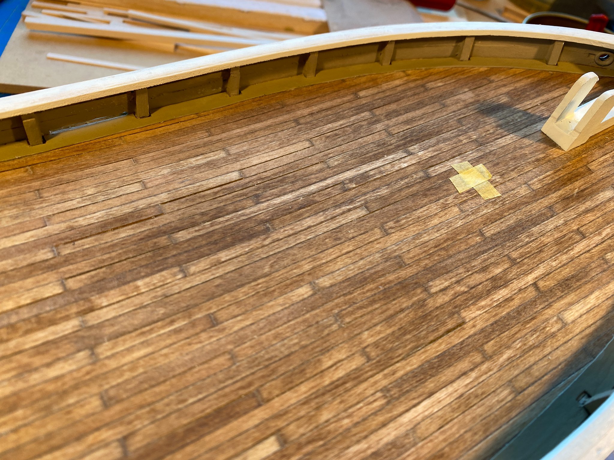
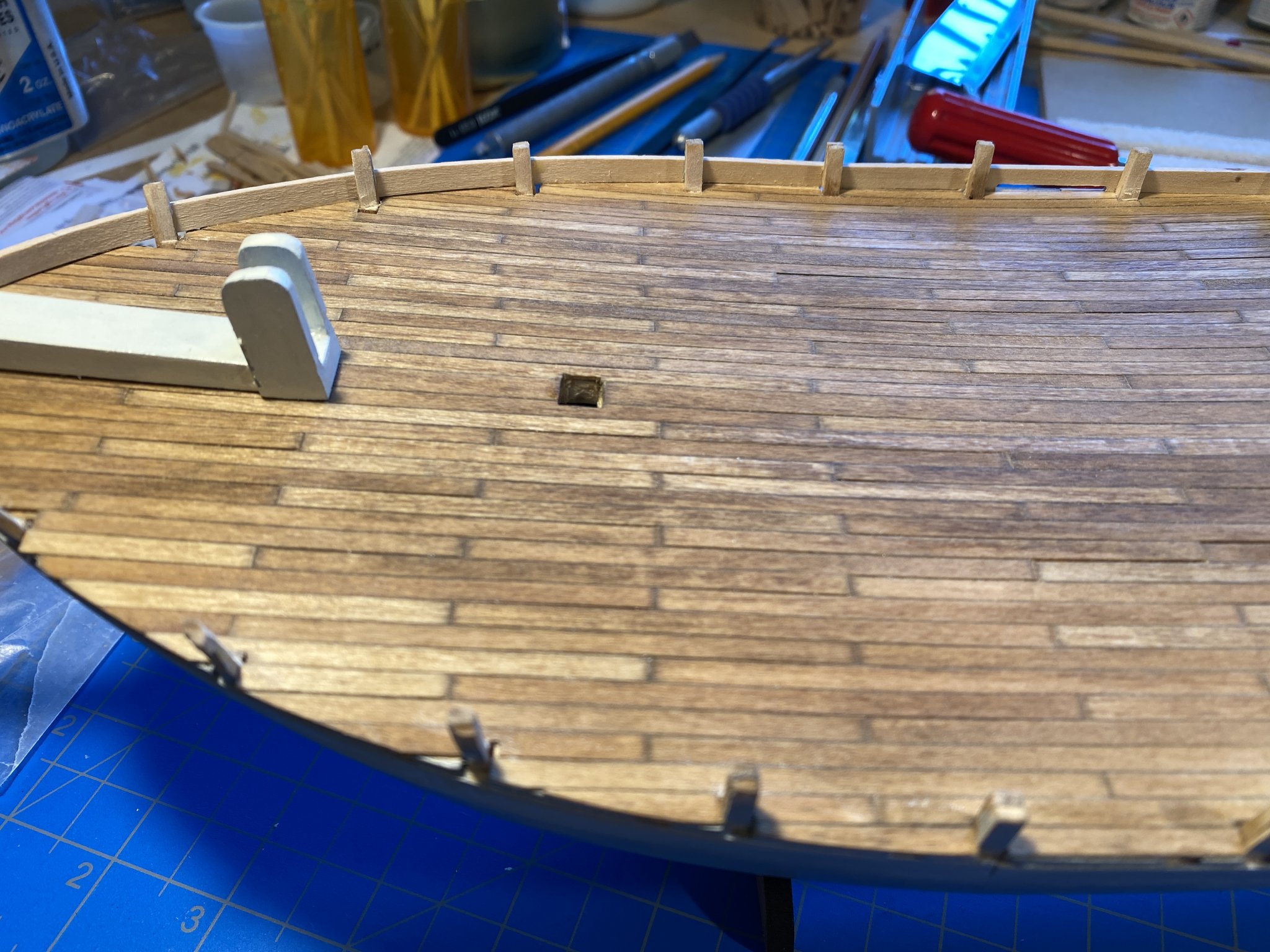
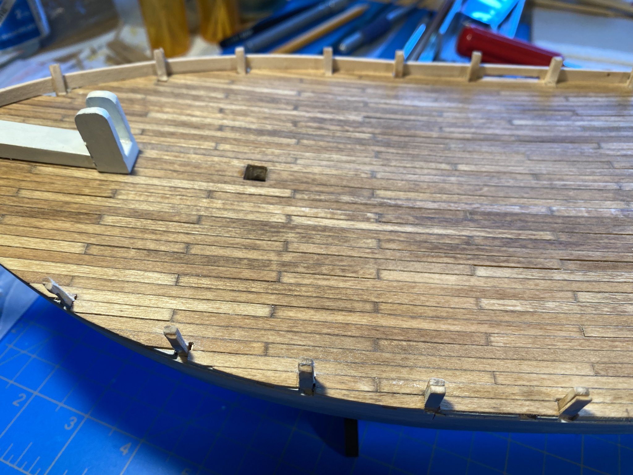
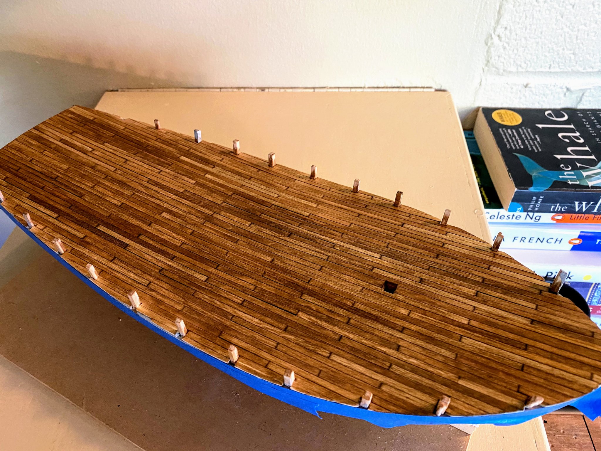
Next project was the deck. I decided I didn’t like the look of the ready made deck that came with the kit, and I instead bought some ⅛ x 1/32 strips, which I cut to 3” lengths. But before gluing any planks to the subdeck, I needed a straight center line and center plank to be sure everything would go in place in straight lines. When I installed the halves of the subdeck, I had to trim one of them, with the result that the line where the two halves join is not the centerline of the boat. I then glued a single center plank in place, a 3/16 x 1/32 piece (a little wider than the other planks to help assure that it is straight). Of course a single plank running the length of the boat is not very realistic, but it won’t be noticeable once the deck furniture is installed. I ran a pencil along one side and one end of each strip to help visually set the planks off from each other (simulating a little calking I guess). Even without the deck furniture, the non-conforming center plank pretty much disappears. I then stained the deck with MiniWax Golden Oak. Once thoroughly dried it’s not nearly as dark as it appears in the pictures. The blue you can see on the upper hull is painters tape; I was a bit paranoid about stain dripping down the sides of the hull. Next project was to finish shaping the bowsprit, add the “mooring bits or knightsheads” (as they are referred to in the plans), and paint. To securely install the bowsprit in place, I put pins through the bowsprit between the mooring bits and forward of the deck on the stem piece. Finally I painted the small eyebands dark grey, and installed one of them on the end of the bowsprit. So as I write this I am a couple of weeks into working on the margin planks (which will be on top of the deck planks but very thin), and beveling and shimming the stanchions to accept the bulwarks. Will post again when the bulwarks are at least partially installed.


- 82 replies
-
- 2
-
-
- spray
- BlueJacket Shipcrafters
- (and 1 more)
-
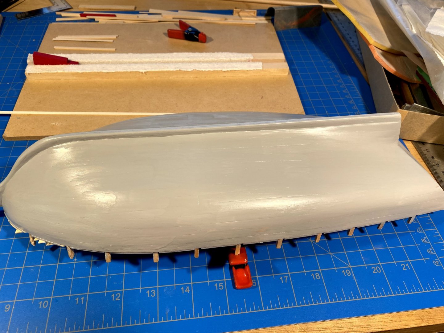
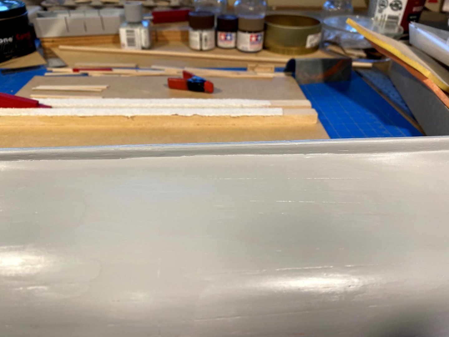
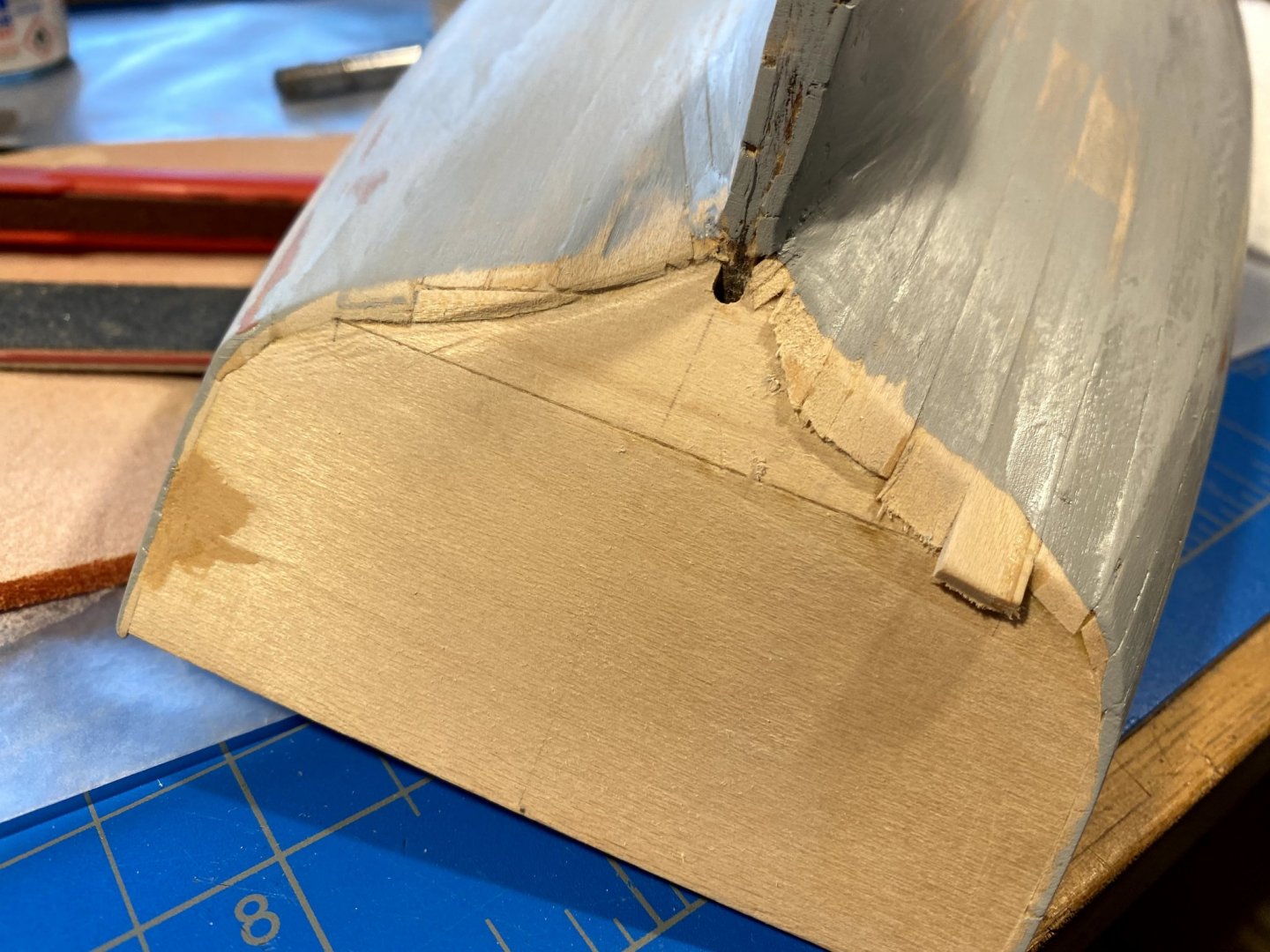
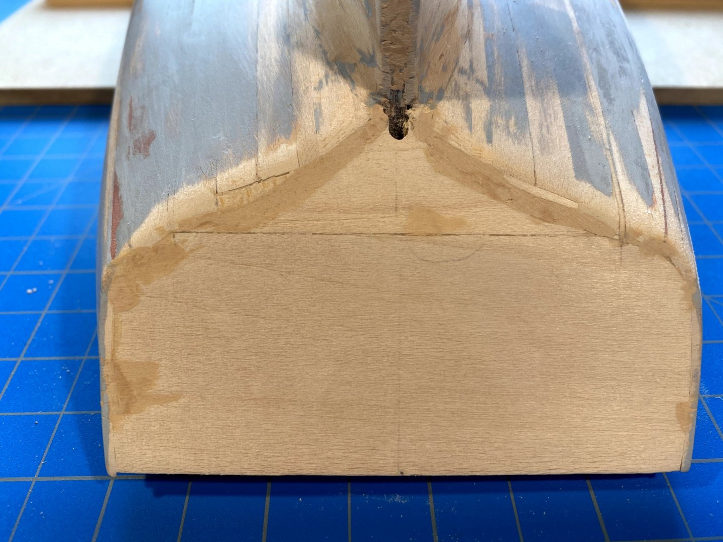
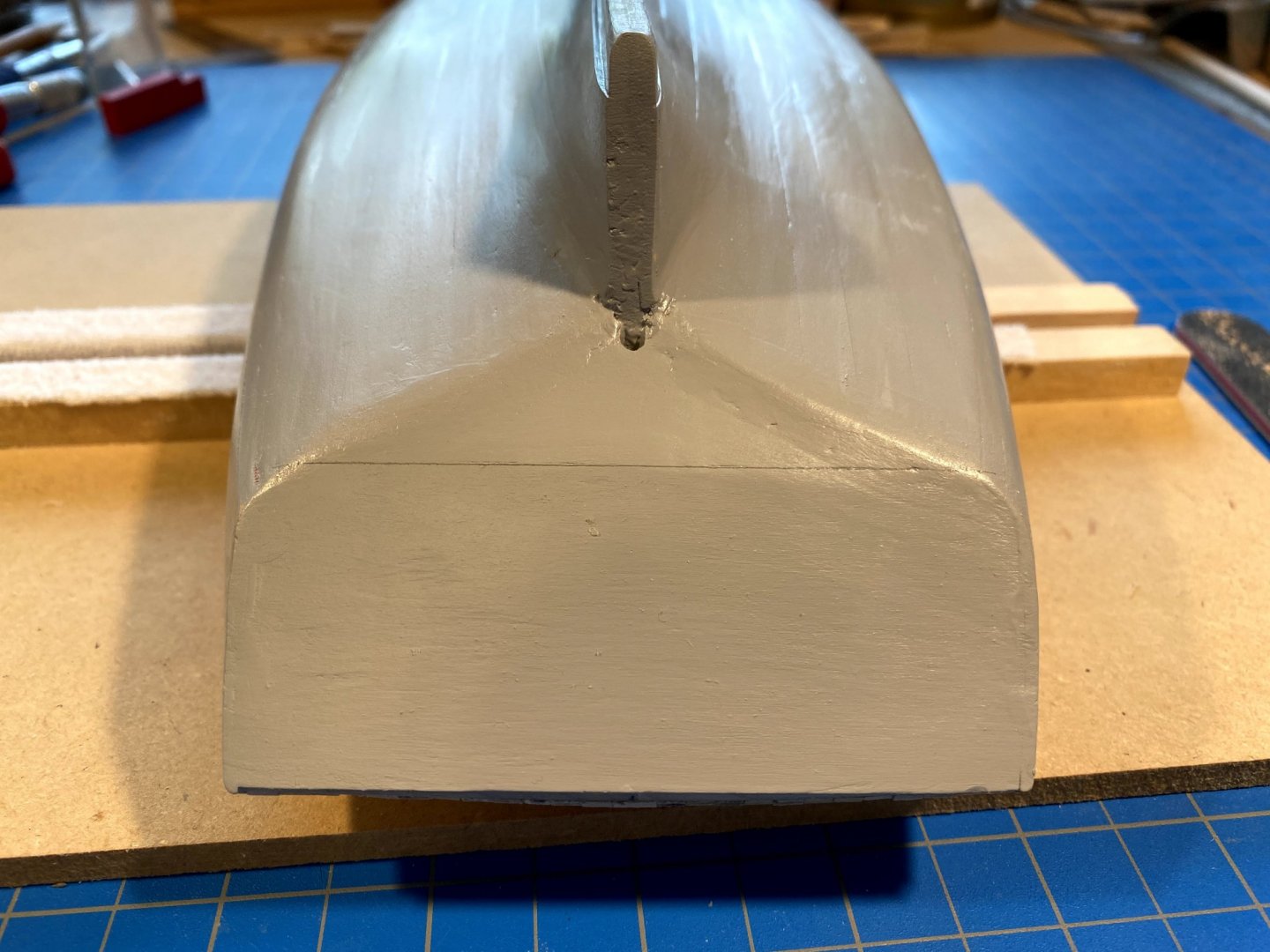
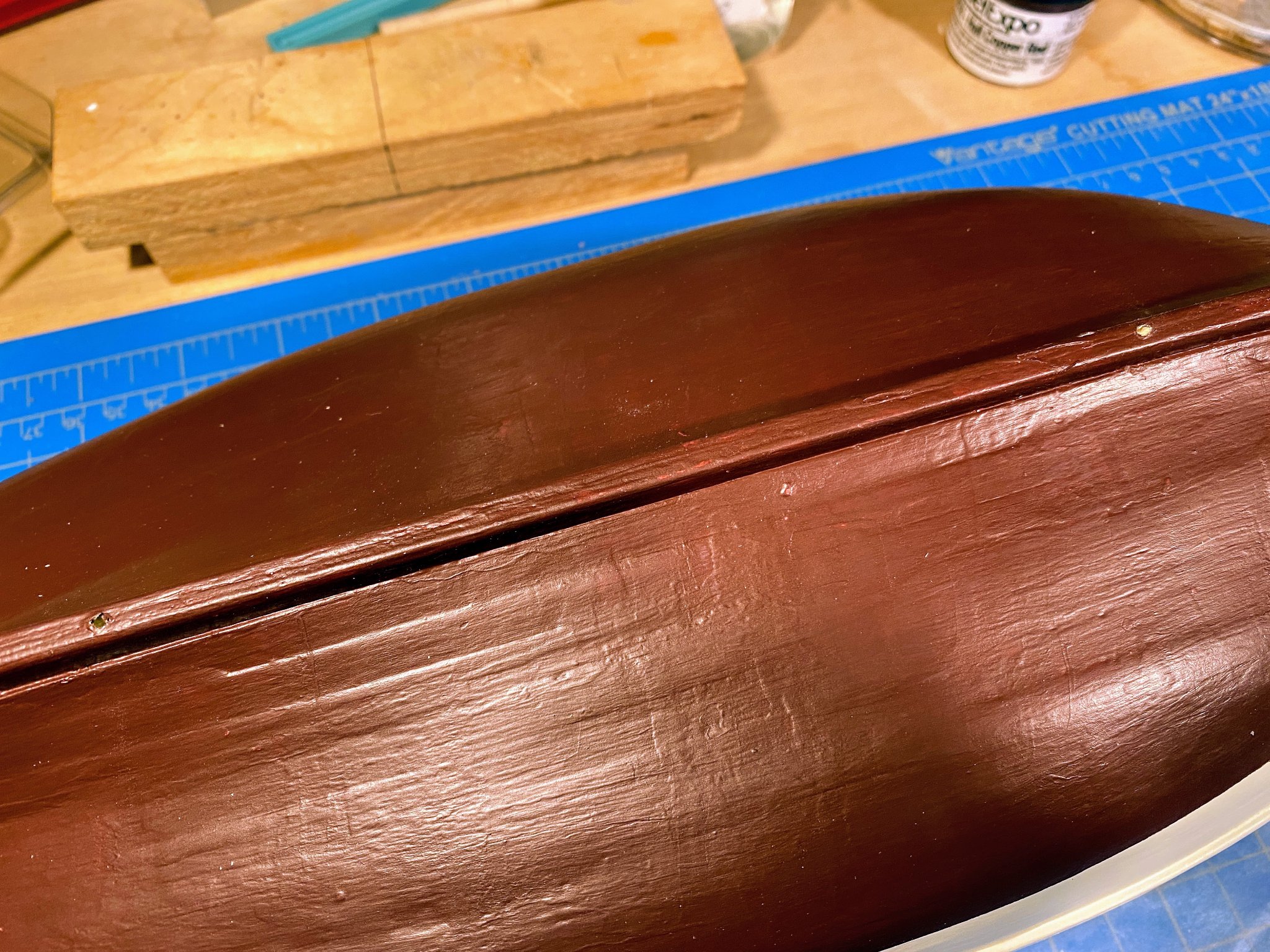
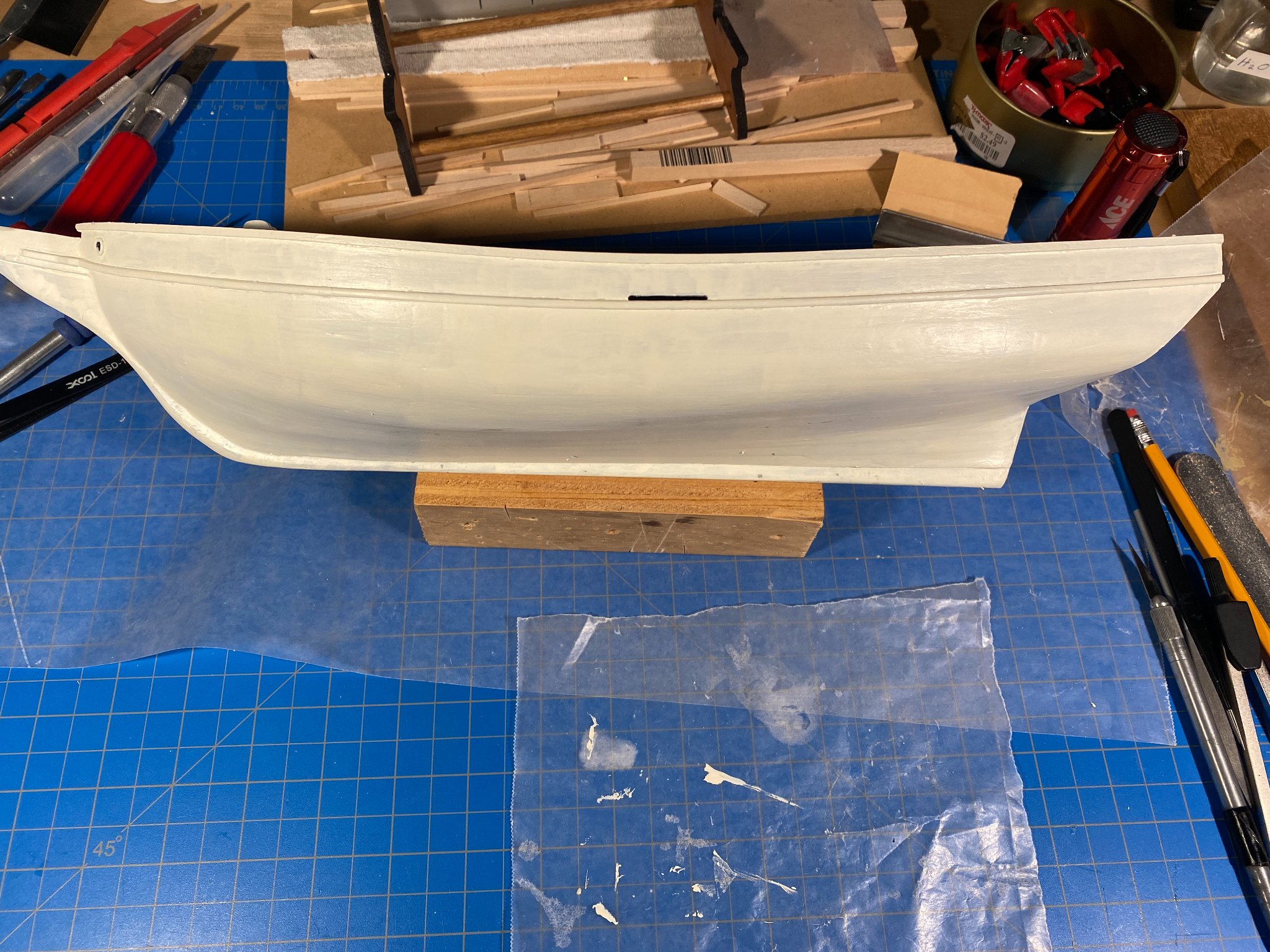
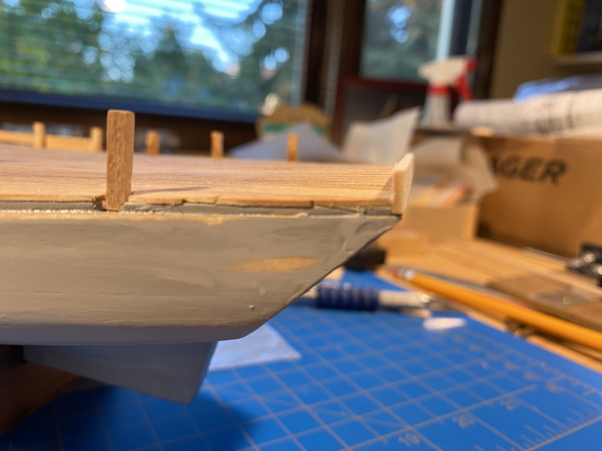
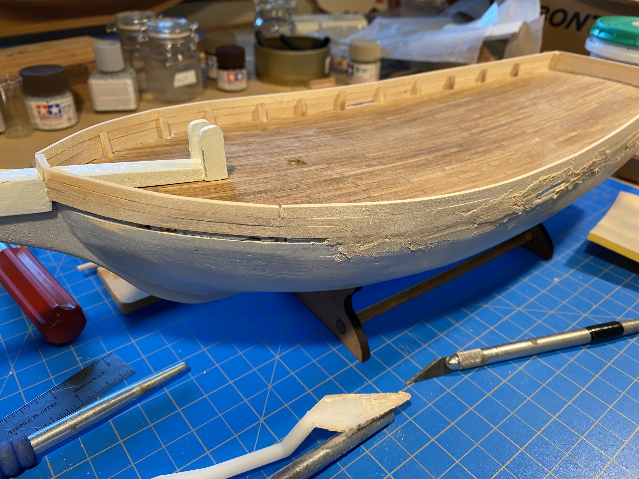
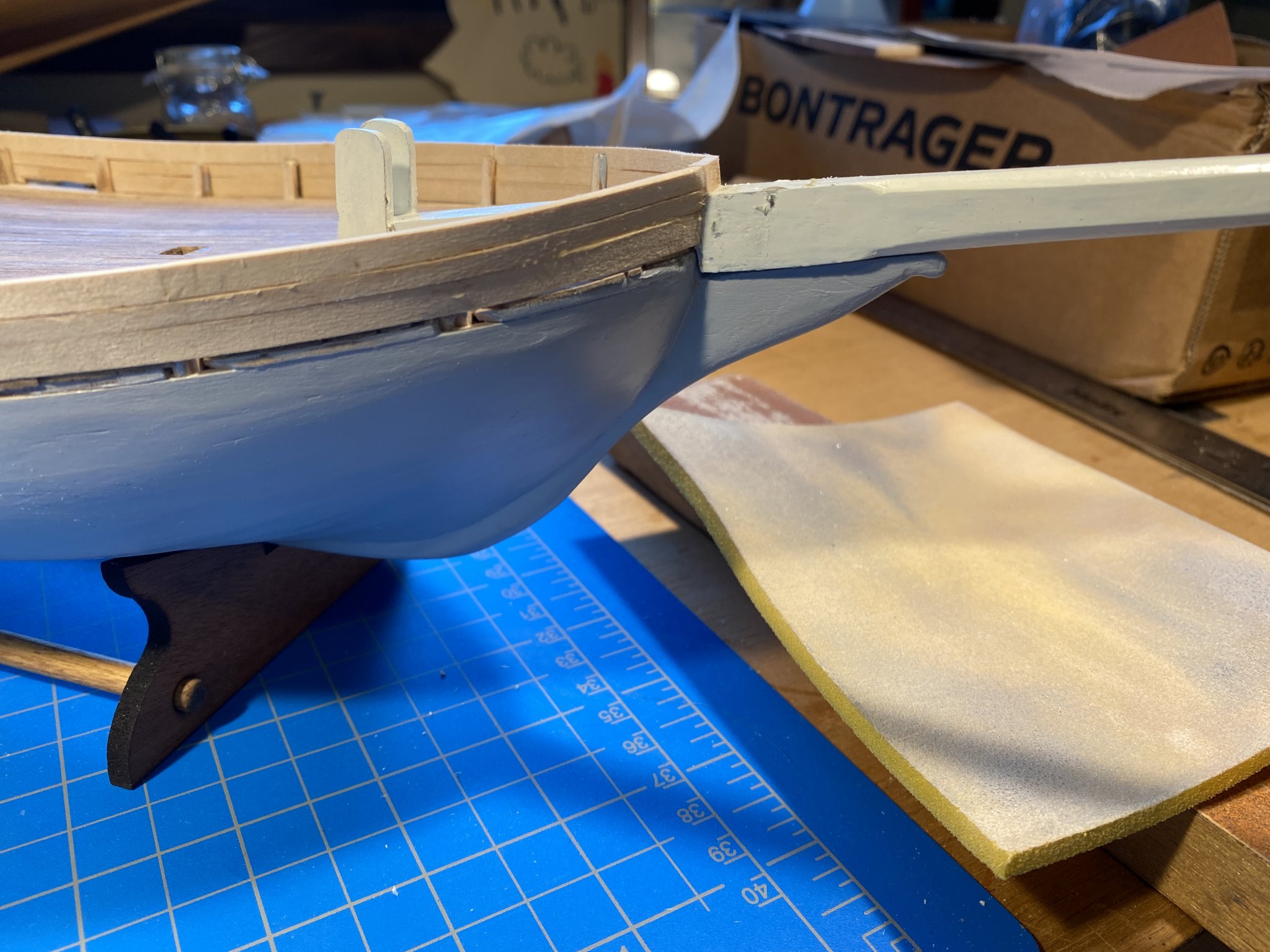
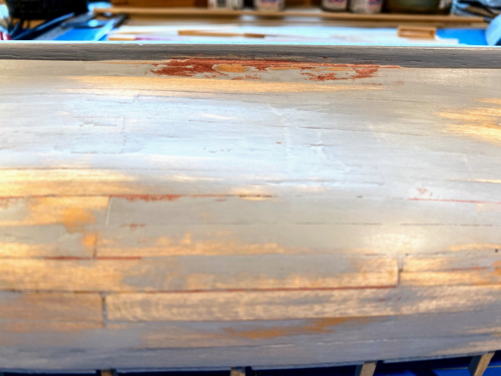
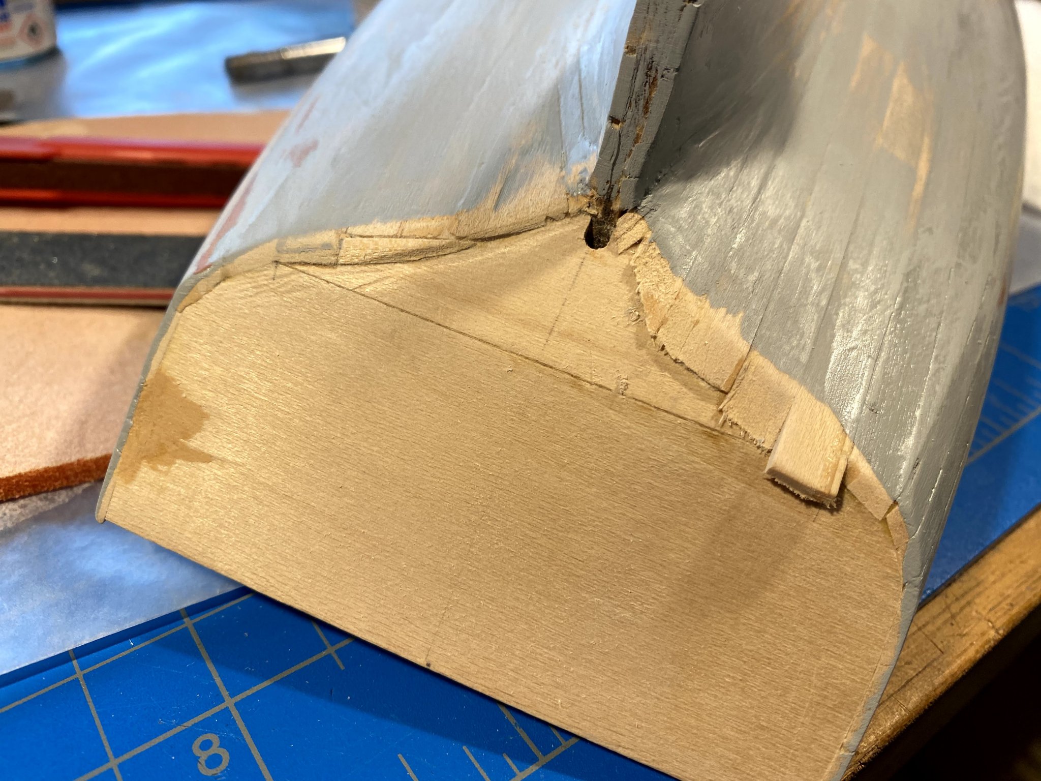
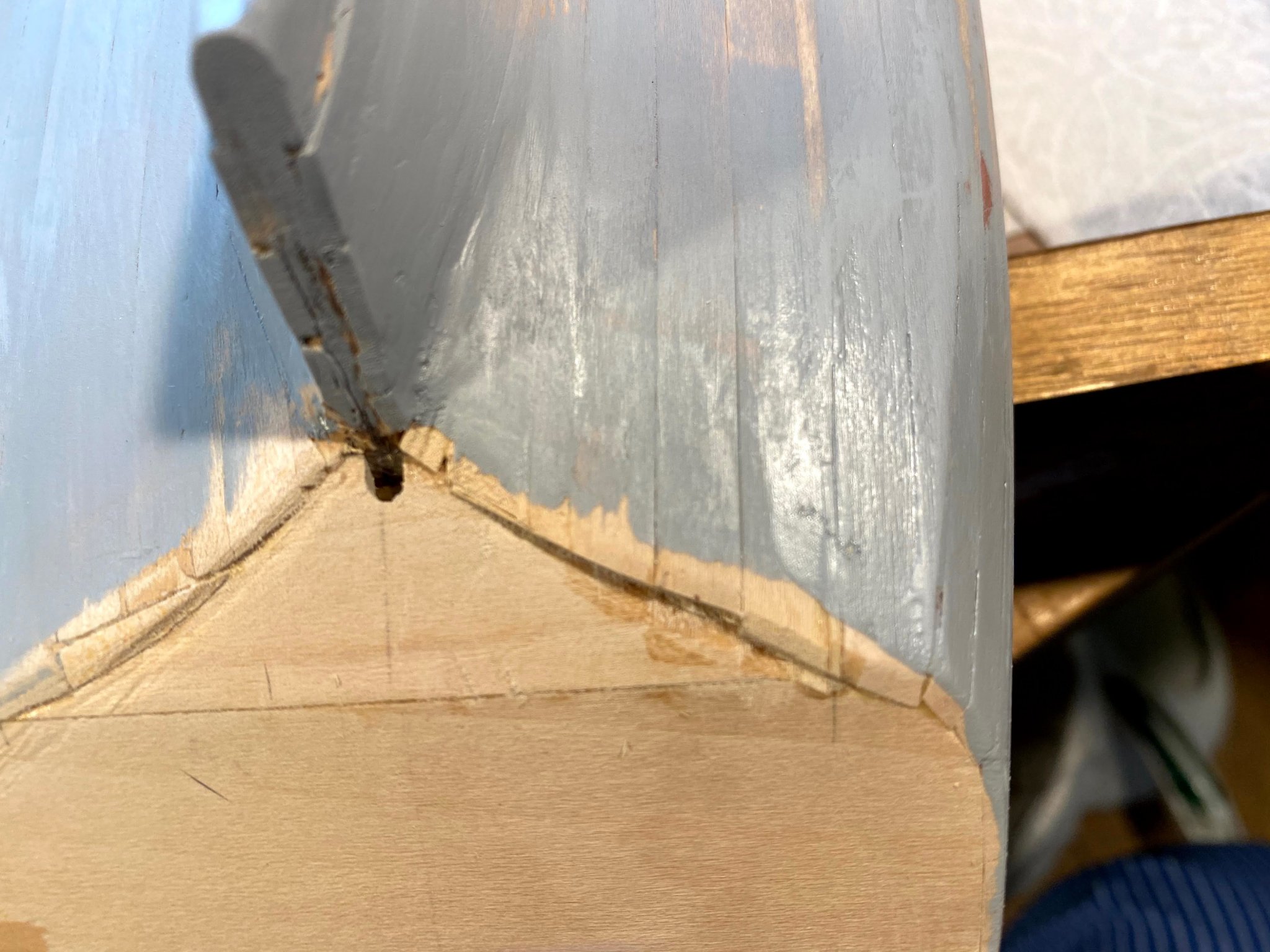
Another long break between posts. A lot of wood filler and sanding. Then came the first coat of primer, which of course disclosed numerous flaws, needing more filler and sanding. After that, much of the first coat of paint was gone. I used Tamiya’s primer, which I discovered is not water based. In its marketing it is said to be gap filling, which I guess is somewhat true. Cleaning the brush it felt somewhat granular, and after the brush dried it was full of dust. Kind of odd in my book. Fortunately it’s an old brush. In any event, after a second coat of paint it’s really beginning to look like a finished hull. At some point I noticed that the garboard plank on one side wasn’t quite straight (it being made of two pieces of wood that I didn’t line up as well as I should have). I clamped a scrap piece of wood to the keel where the dip was, filled it with wood filler, sanded and sanded, and it came out looking better, but there's still a small dip. One challenge I had (backtracking a bit) was the where the planks meet the lower transom. Hard to see in the pictures, but the lower transom slopes in so much that the angle between it and the planks has got to be at least 160 degrees or more; in other words they almost butt end to edge. But I simply overlapped the planks over the lower edge of the transom, then sanded a lot. I had to do so much sanding that the planks became too thin, and a small hole or two developed. I added a couple of scrap pieces of wood, a lot of wood filler, and did a lot more sanding, and after painting it looked better than I expected. It’s far from perfect, though, and I might not be satisfied with the result but for the fact that when the finished boat is displayed, that underside will be almost impossible to see. Hopefully another post coming shortly.


- 82 replies
-
- 2
-
-
- spray
- BlueJacket Shipcrafters
- (and 1 more)
-
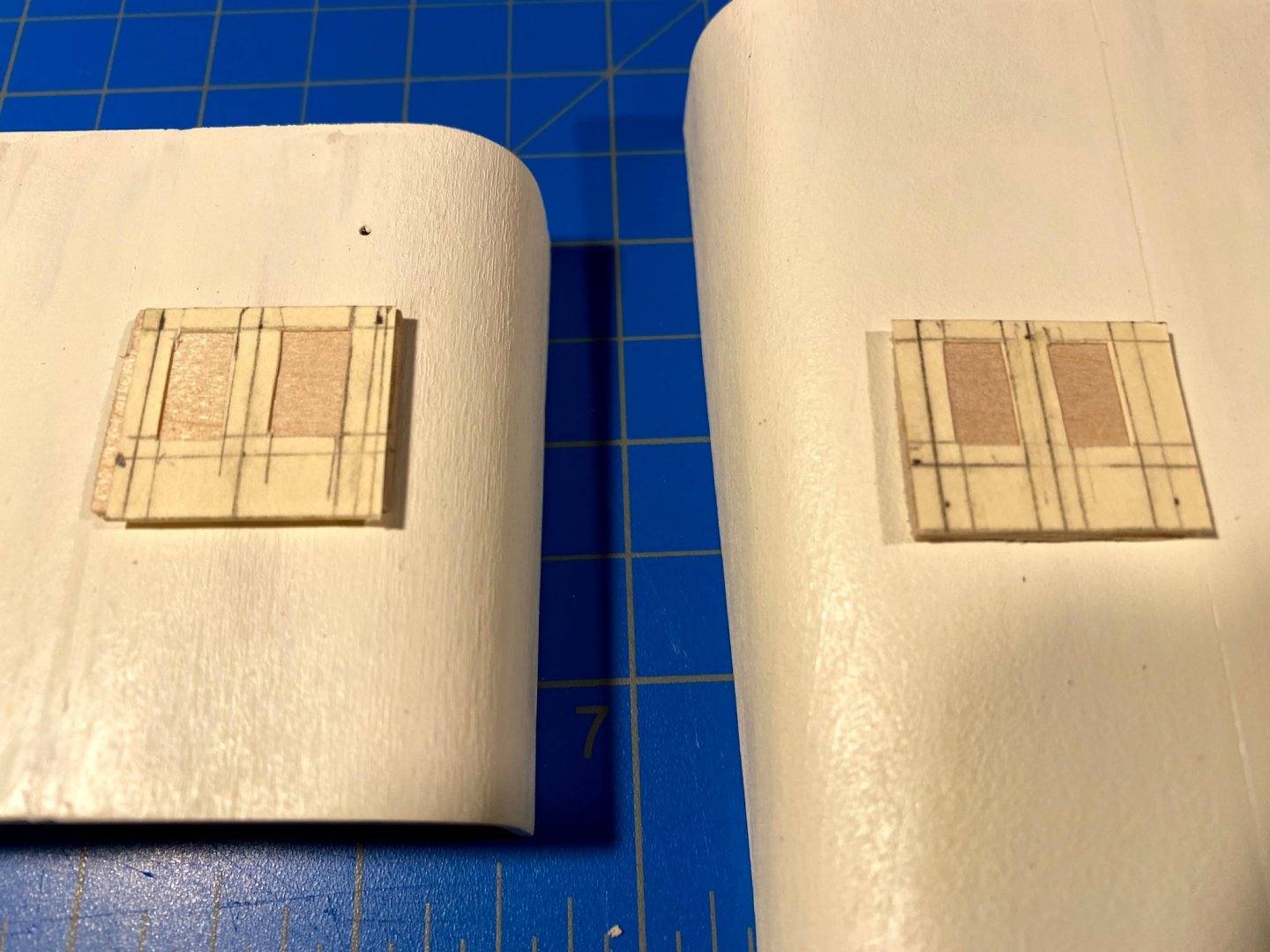
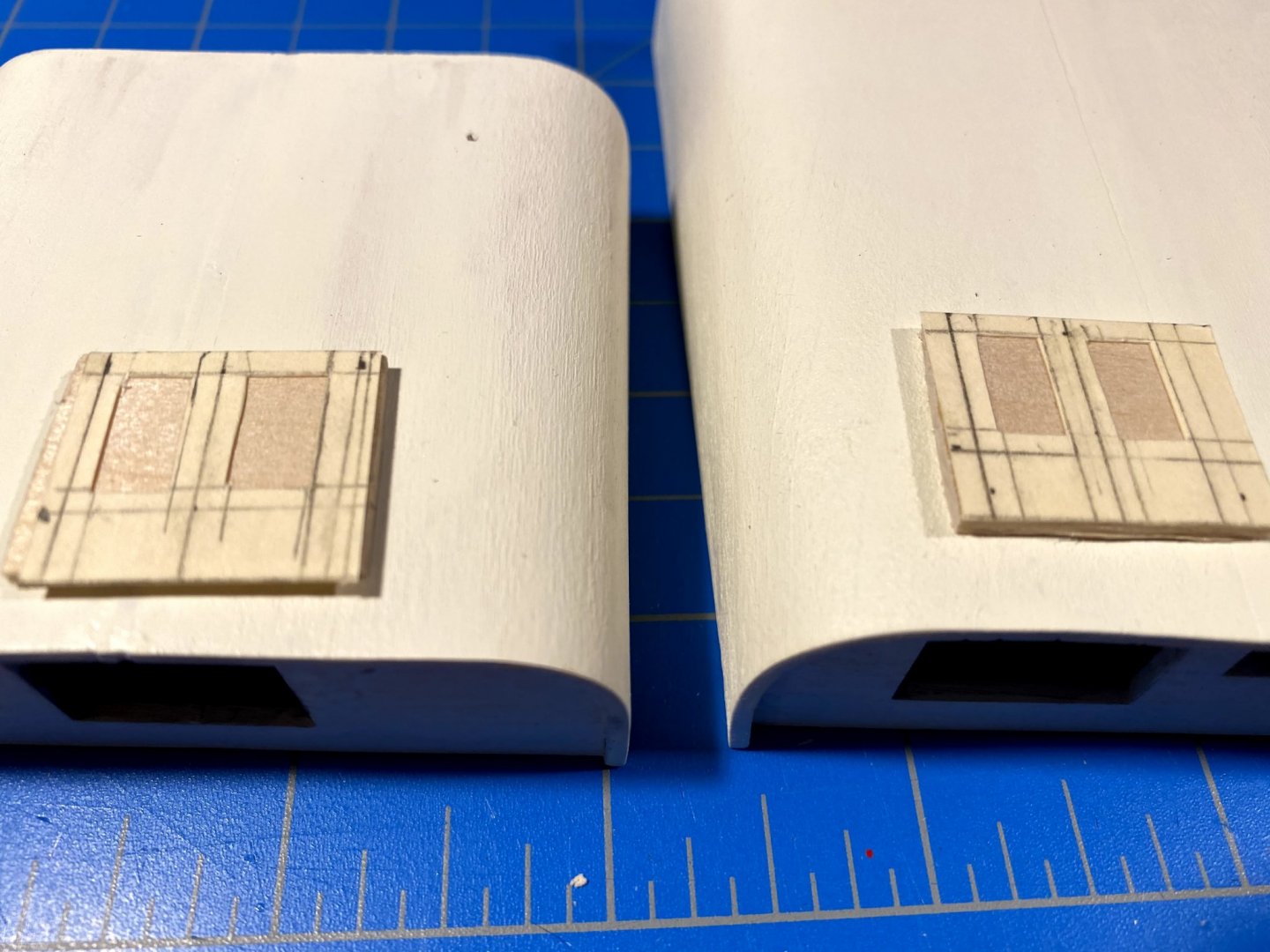
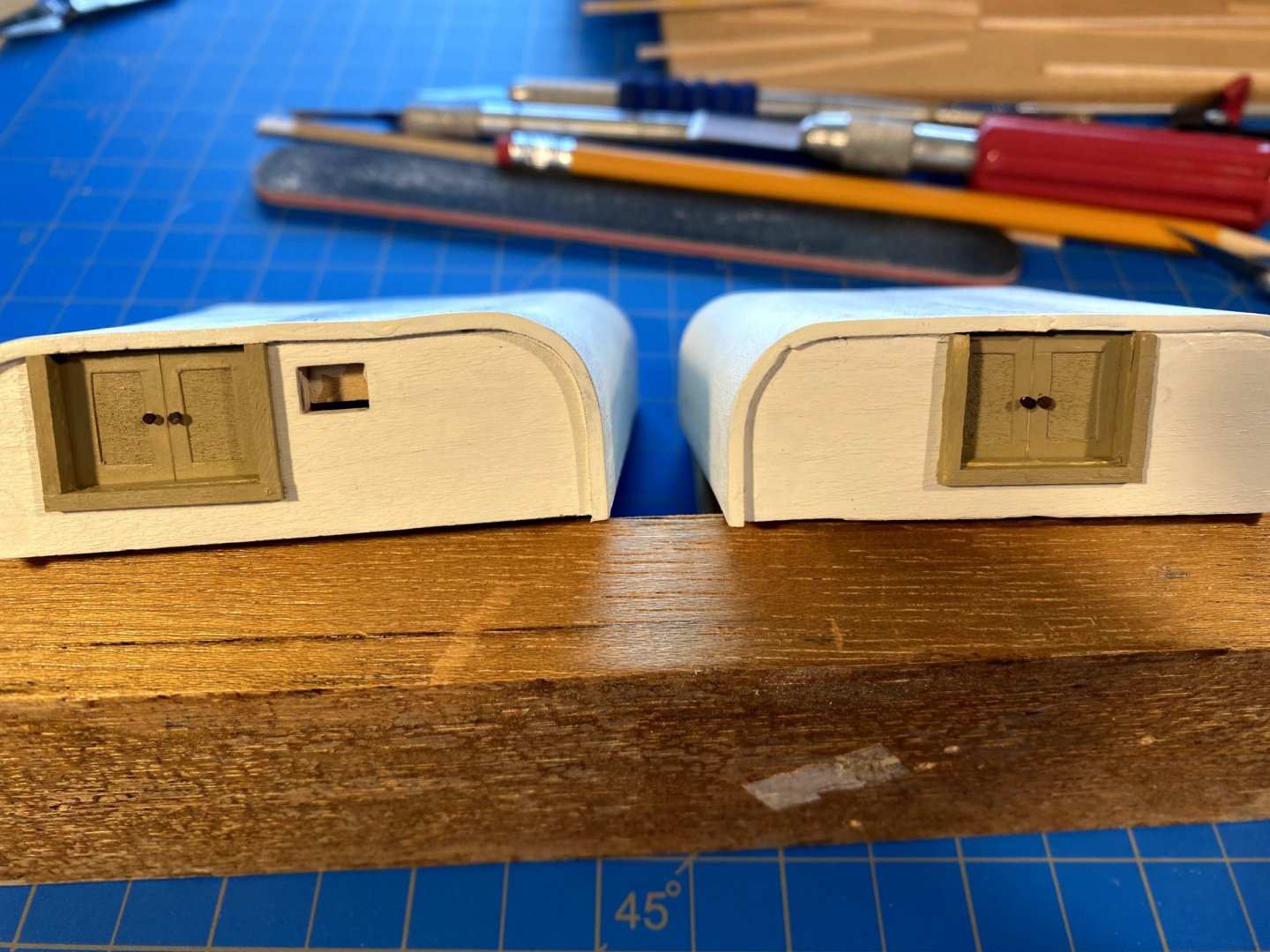
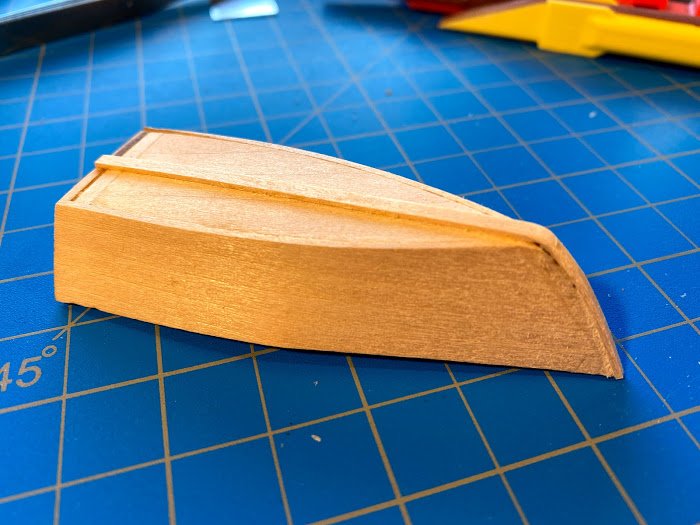
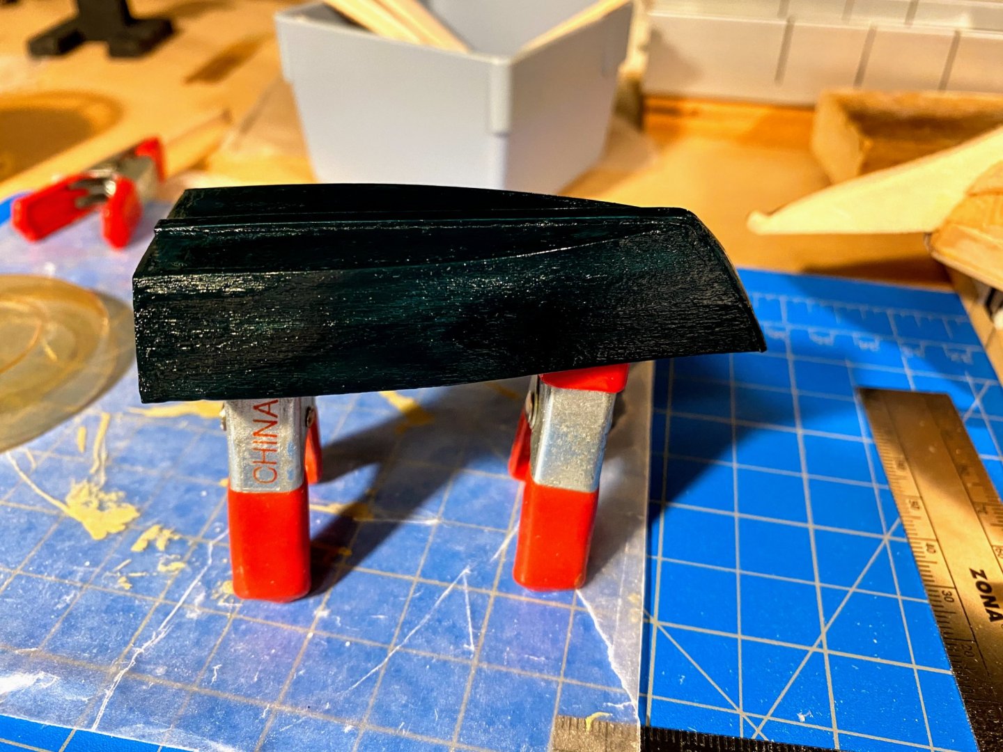
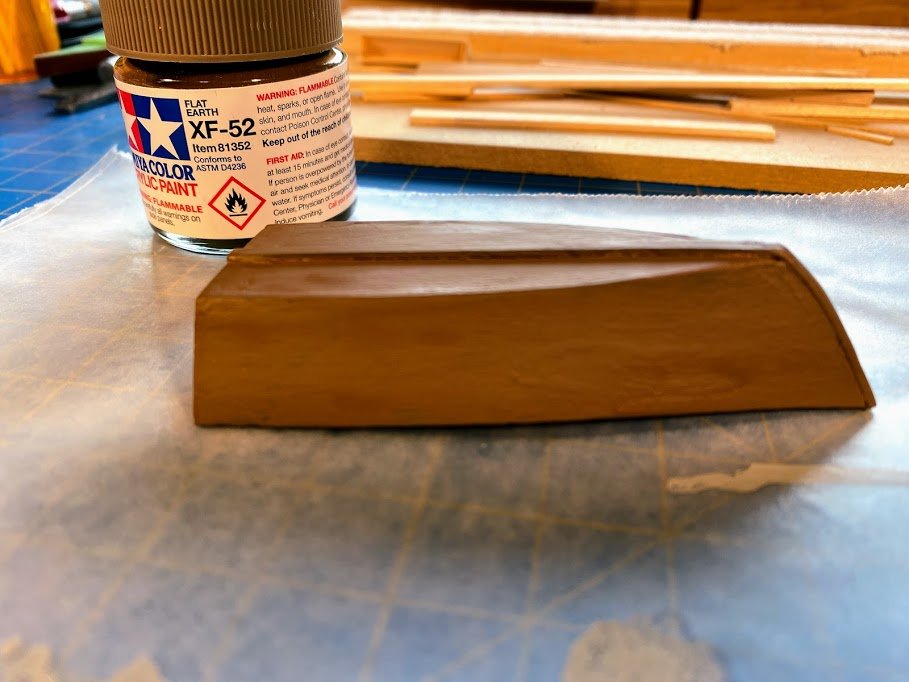
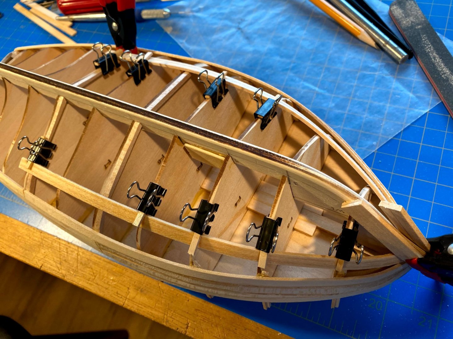
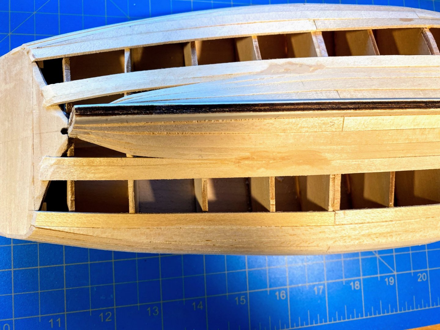
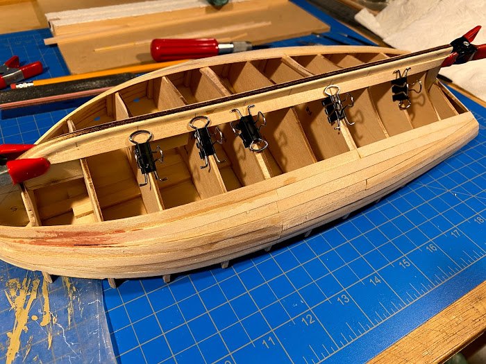
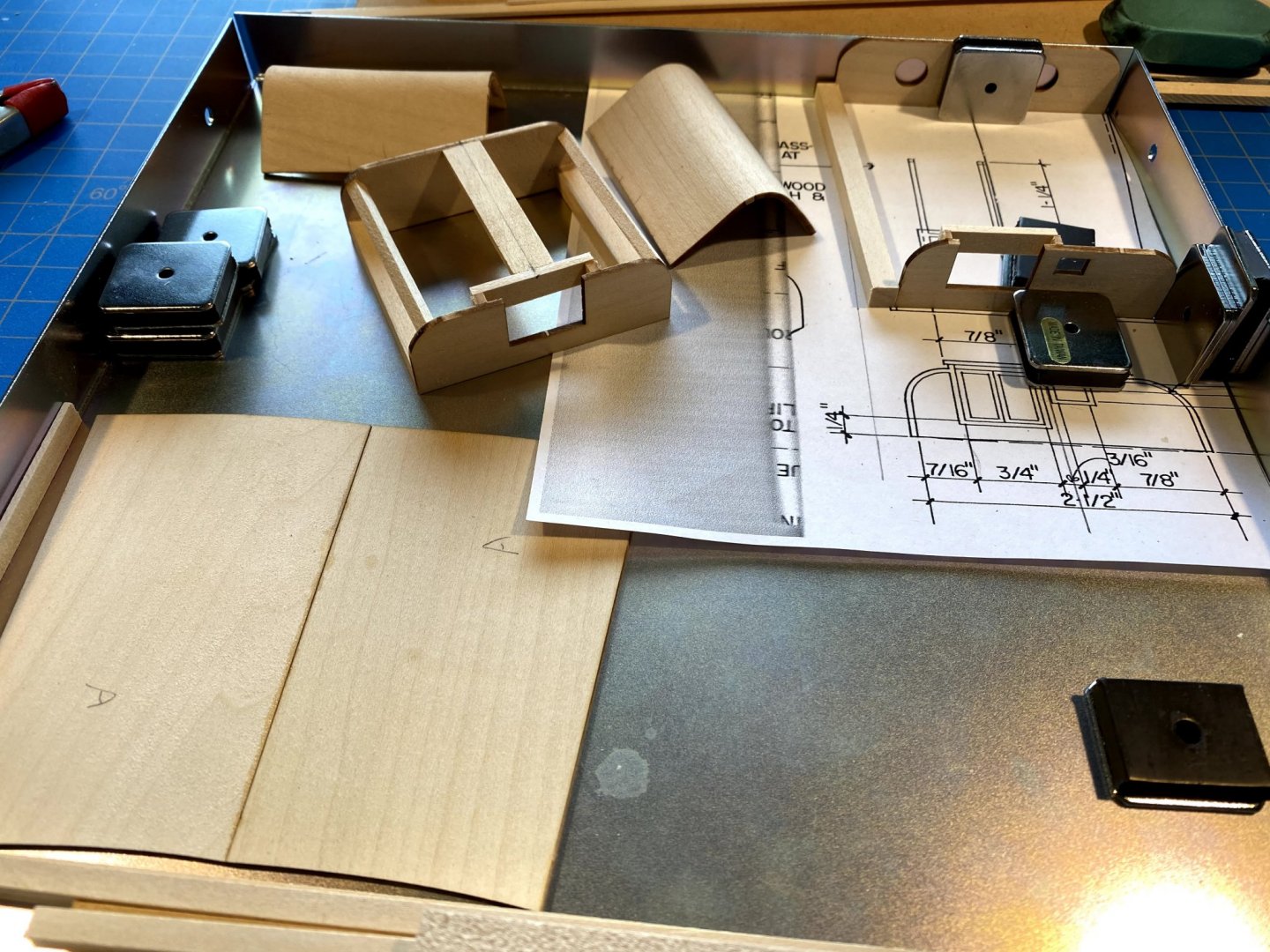
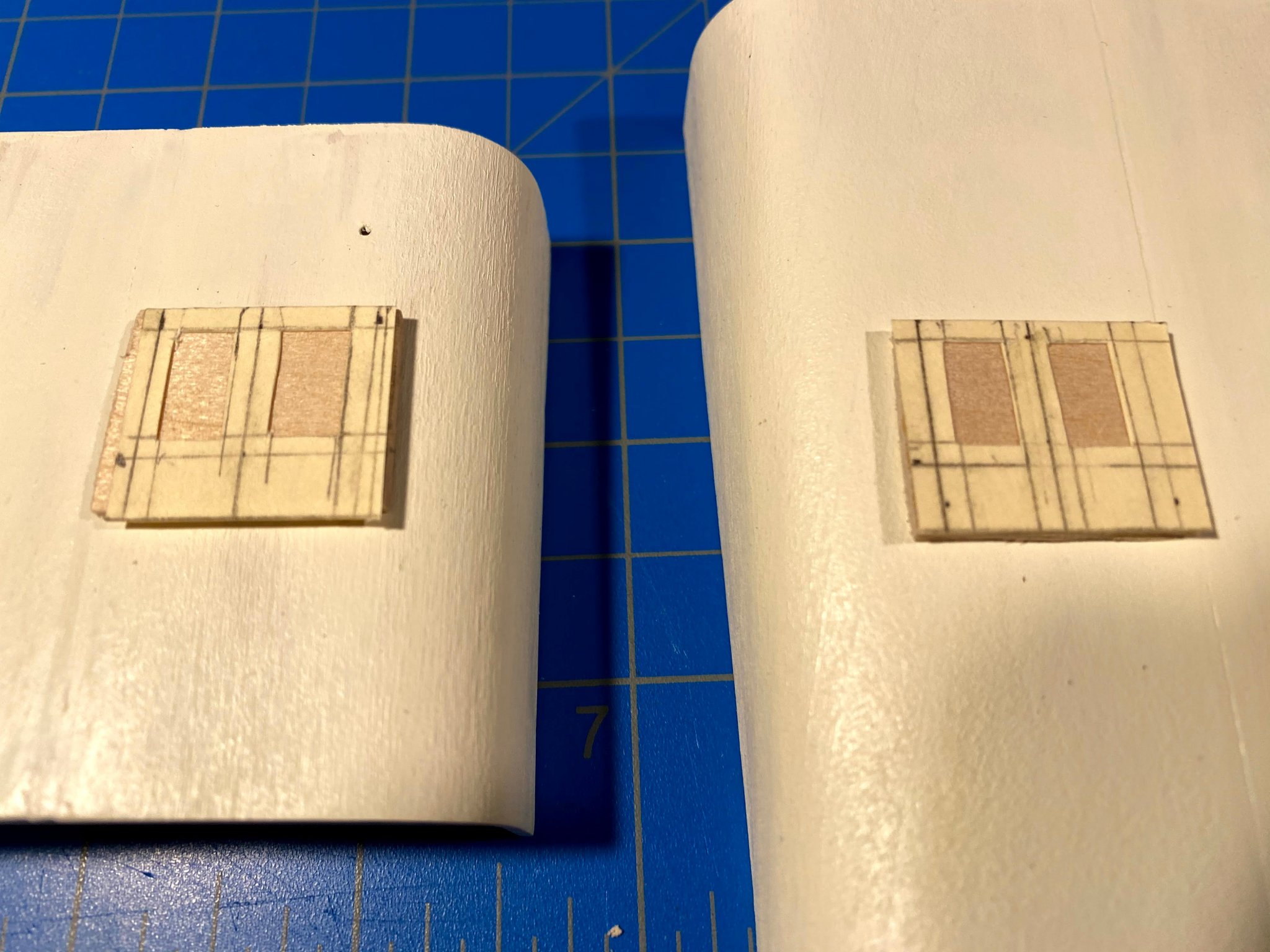
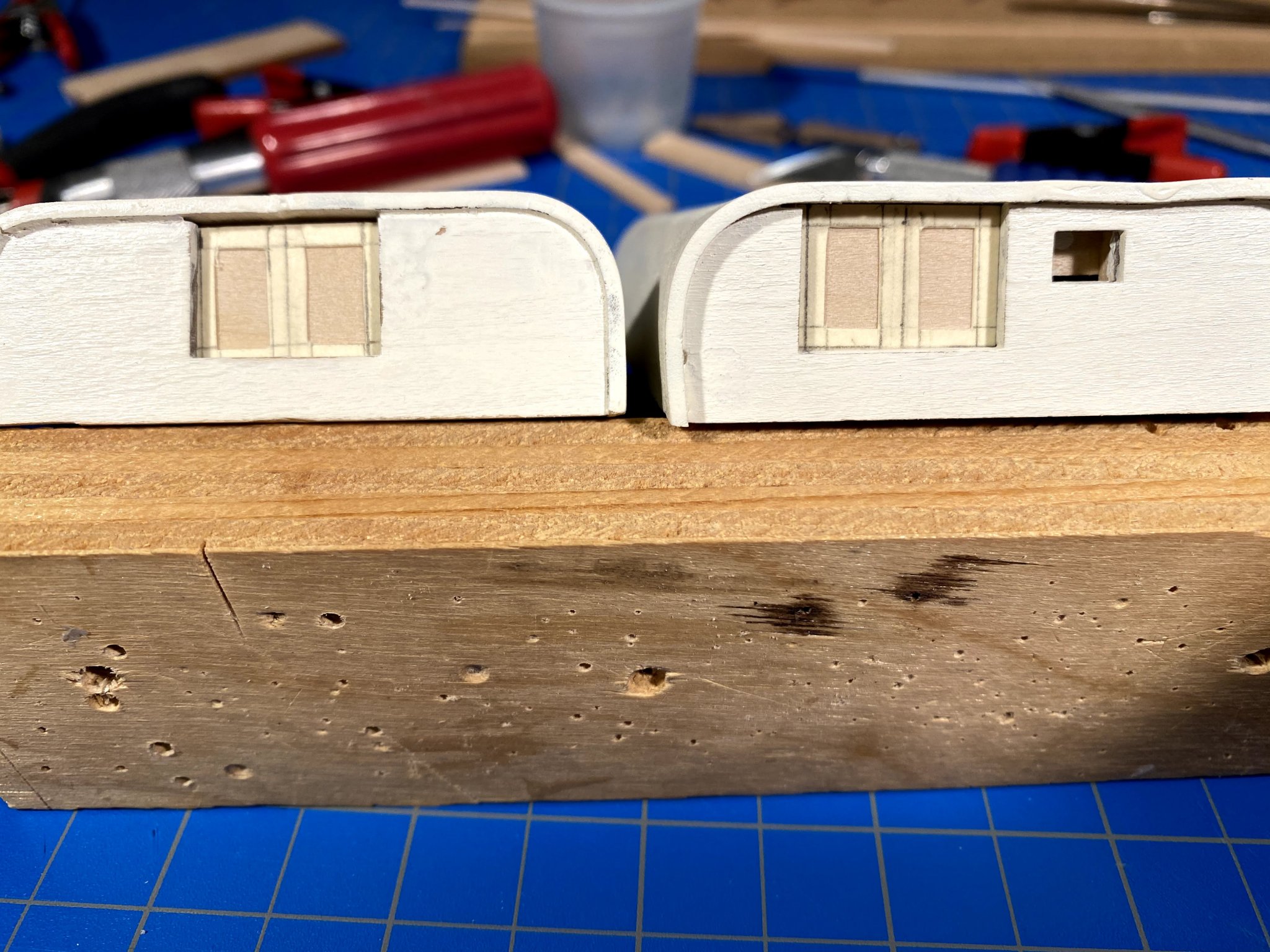
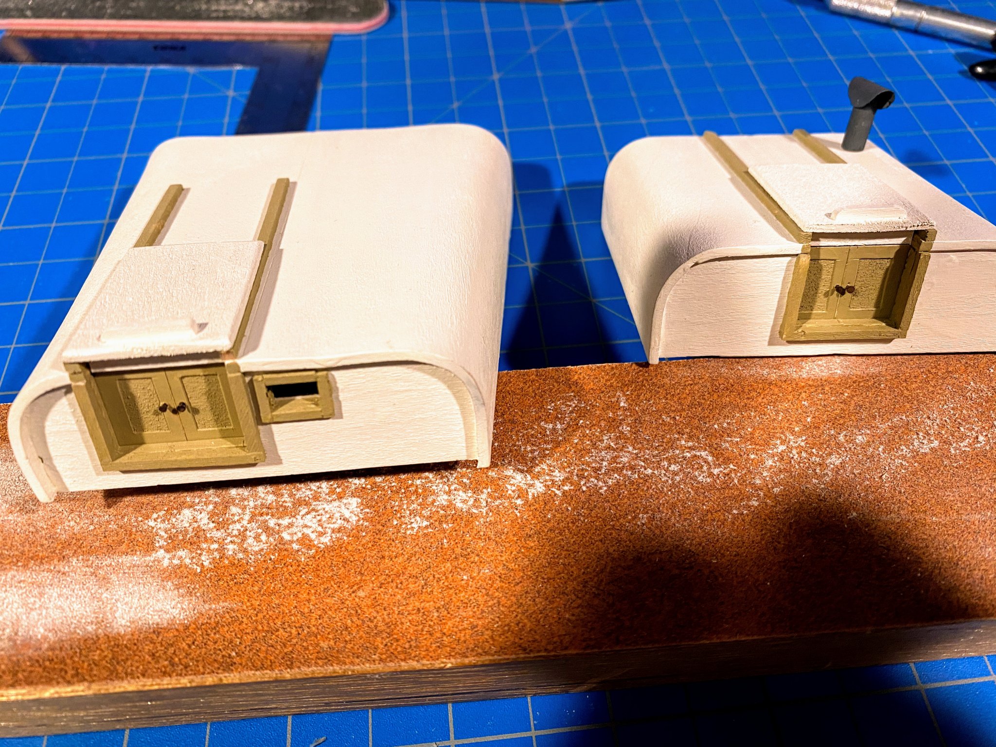
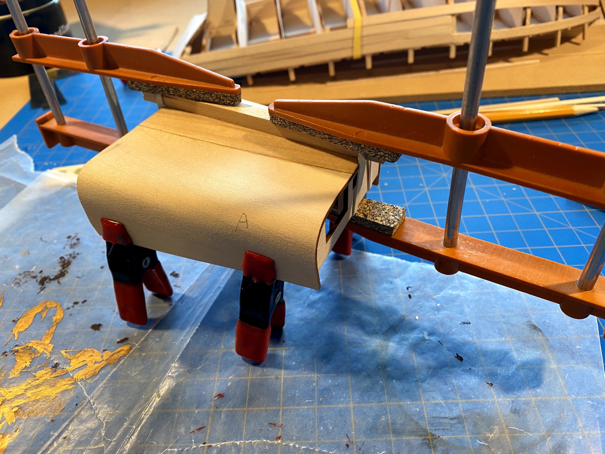
As mentioned in my post from several weeks ago, waiting for things to dry on the hull gave me an opportunity to work on other parts of the build. Once the deck cabins were built . . . . . .I moved on to trim for the doors and frames for the doors and window. I saw in a Chuck Passaro practicum I downloaded some time ago from the Model Shipways website (Sultana? Phantom?) the suggestion of using card stock rather than strips of veneer to add detail to such things as doors. I cut up an old manilla folder, finding it much easier to cut out the center section first, then cut the perimeter second. I glued the same to some scrap 1/16” sheet, and the doors were ready to paint (dry fitted but not glued in the third photo below). This brought up the question of color. The instructions say the boat was probably all white, but that “buff, tan and light grey” were commonly used on similar boats in addition to white. I like to use color to highlight detail, sometimes even when it may not be completely historically accurate, and this seemed like a good place to add some color. Finding I had a handful of Tamiya paints lying around to choose from, I eventually chose “buff”. I painted, then glued, 1/16th square strips around the hatch opening and window, similarly painted the doors, and used the same strips to make tracks for the sliding hatches. For more detail (before I glued the doors to the structures), I ran a sharp Exacto knife down the center of the manila folder trim, to simulate a separation between two doors, and took the smallest nails I could find and turned the nail heads into door handles. And finally I painted the port hole inserts in the aft cabin the same dark grey I used for the stack on the forward cabin. The other thing I worked on was the dinghy, a quick fun little project. After punching out the laser cut pieces, I first glued the transom and the frame to the bottom, adding some 1/8” square strips for rigidity and to help assure the desired 90 degree angles. The bottom was about 1/16” short, so I added a strip at the stern (hard to see this photo, but it’s clear in the one further below, finished but unpainted). I then soaked the sides in hot water for about half an hour, then easily bent them around the bottom and the frame. Holding everything in place while it dried proved to be a challenge, but by constructing a small V-shaped mold I was able to hold everything together at the bow. The instructions say that Slocum once referred to his dinghy as “green”, so they suggest painting it “bright green” if white isn’t used. I had some very dark green paint hanging around, and I used that instead. Unfortunately I didn’t realize that the paint was gloss instead of flat, nor did I realize before using it that it’s really dark. I had several shades of brown and tan paint around, one of which was flat Earth from Tamiya. Once I saw that, the irony was just too great, and I knew I had to paint something on Joshua Slocum’s boat Flat Earth. That ‘something’ ended up being the dinghy. Fortunately it covered the dark green very well. I think I will add a rub rail along the side of the hull, but I’m not there yet.


- 82 replies
-
- 4
-
-
- spray
- BlueJacket Shipcrafters
- (and 1 more)
-
Every so often I end up with an extra photo or few which are at the end of the post, but I didn't put them there. Still haven't figured out why. Here the third of three at the end doesn't belong there.
-
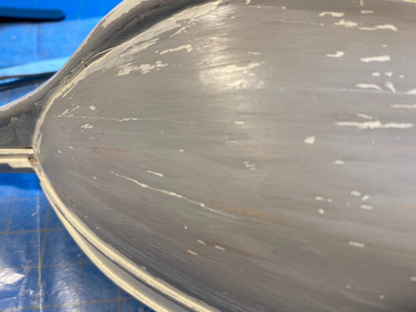
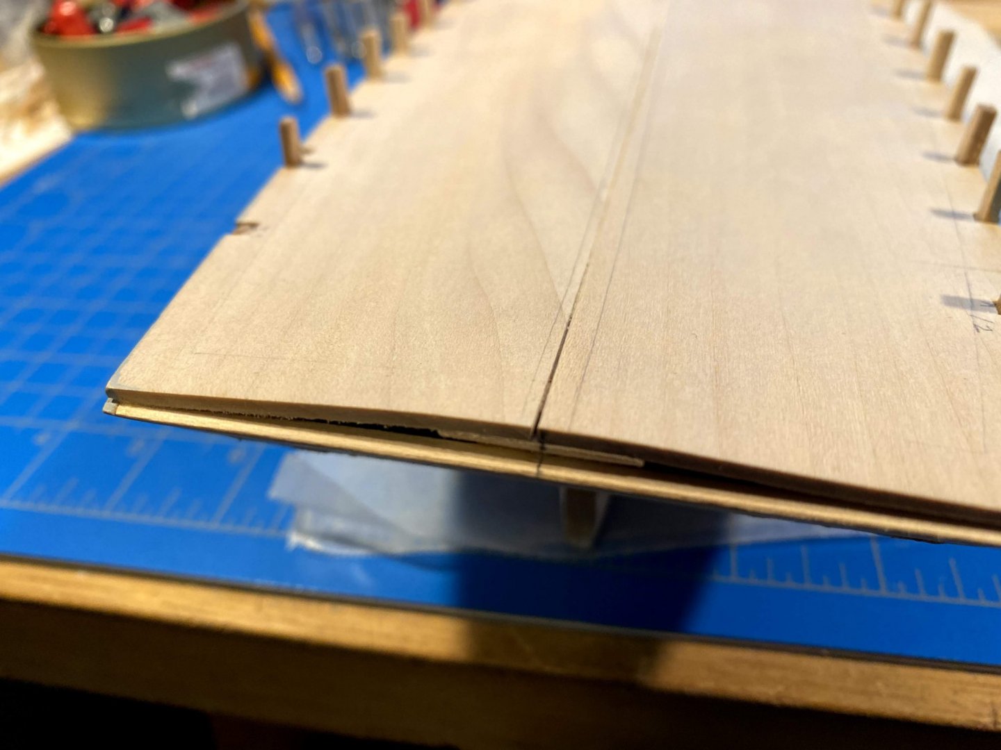
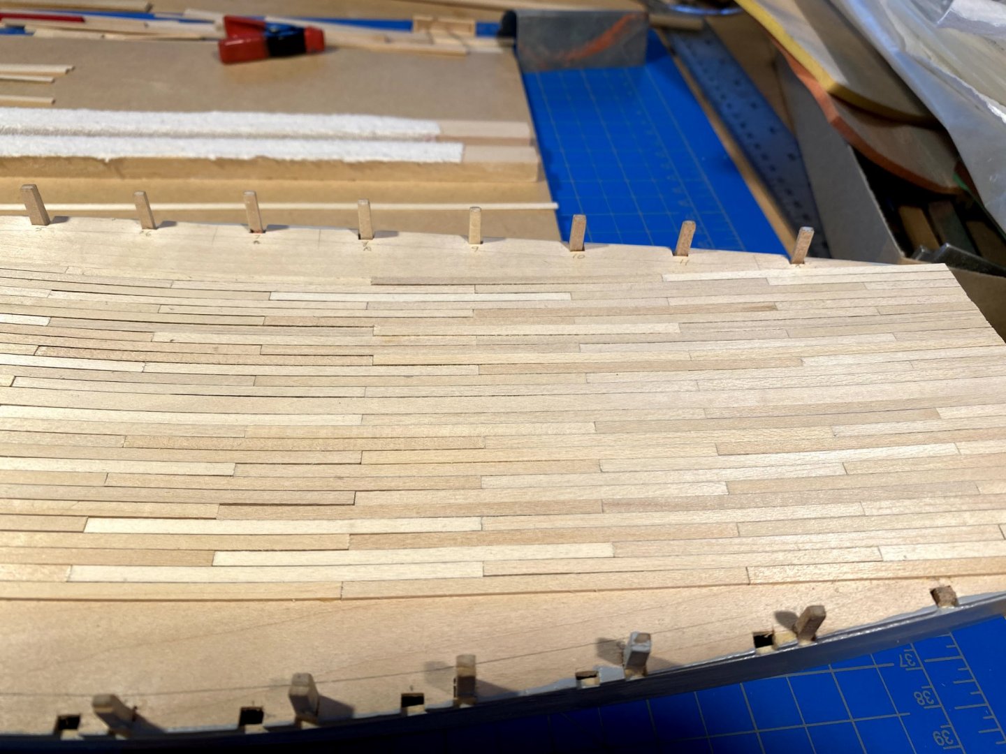
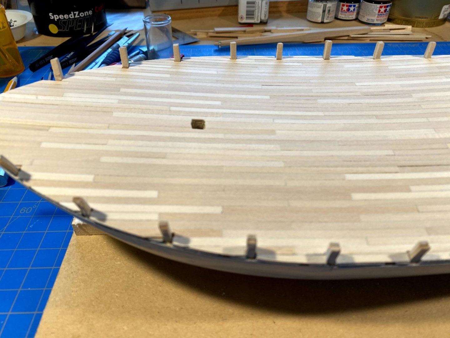
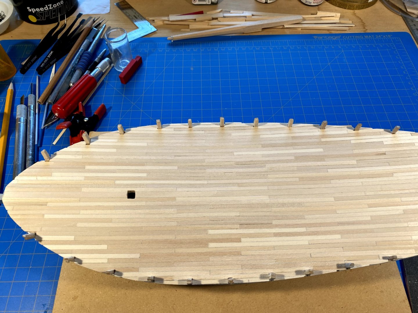
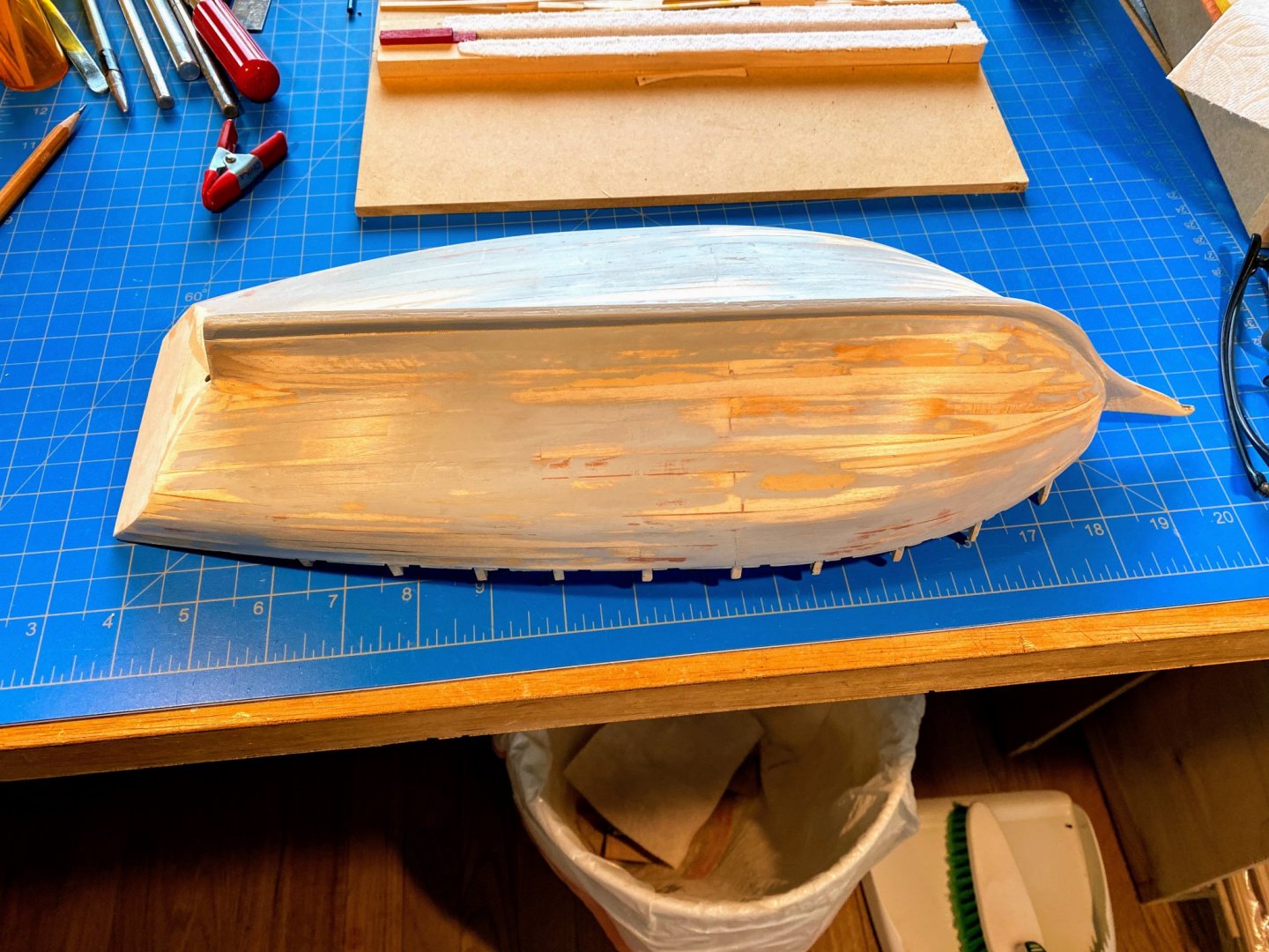
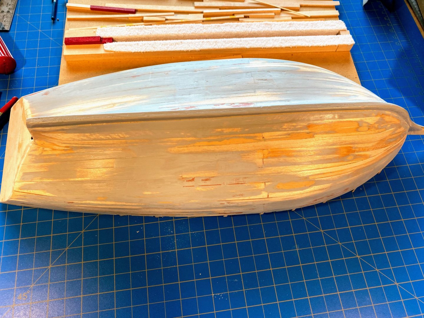
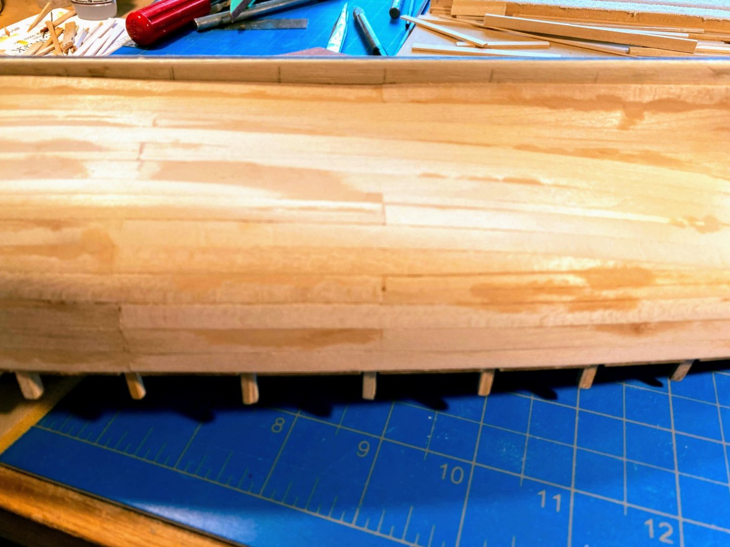
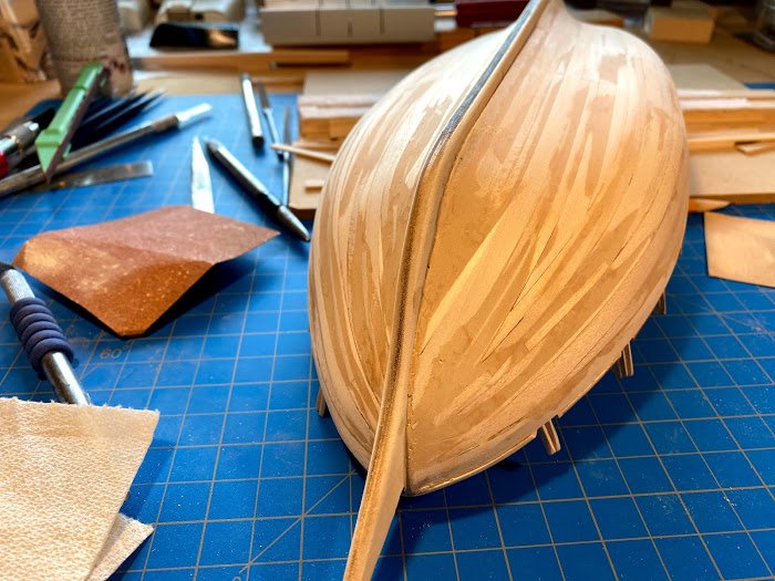
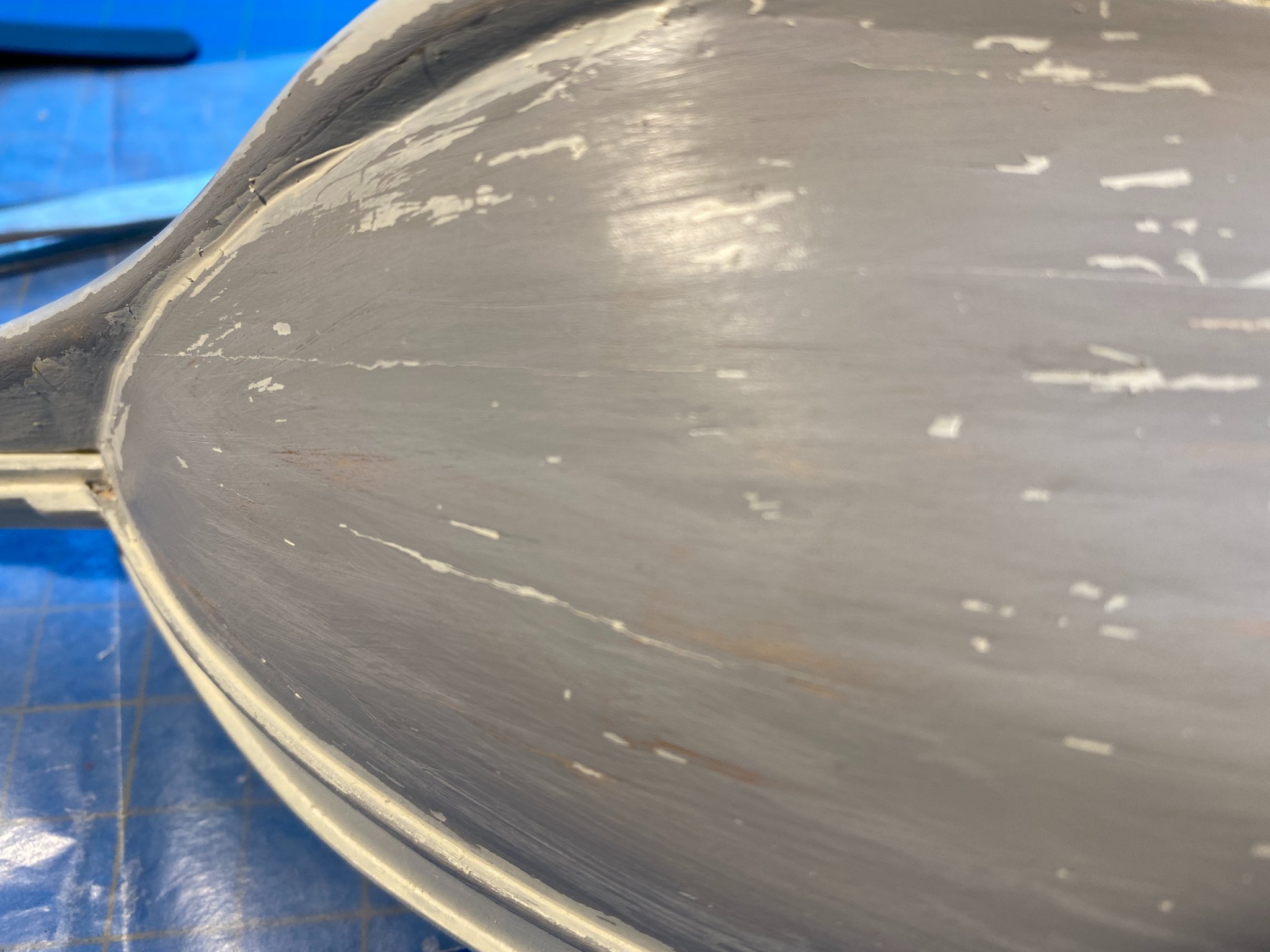
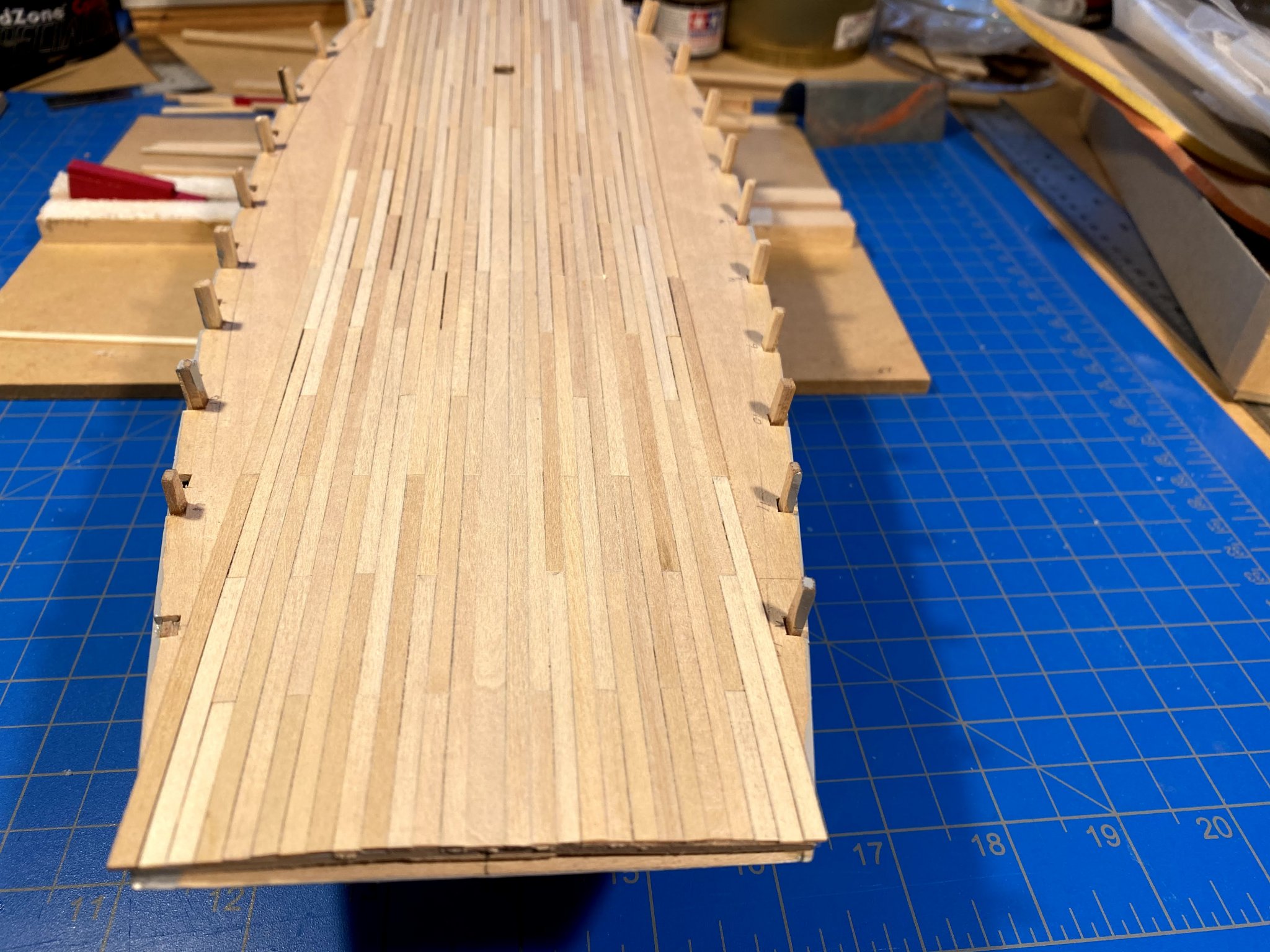
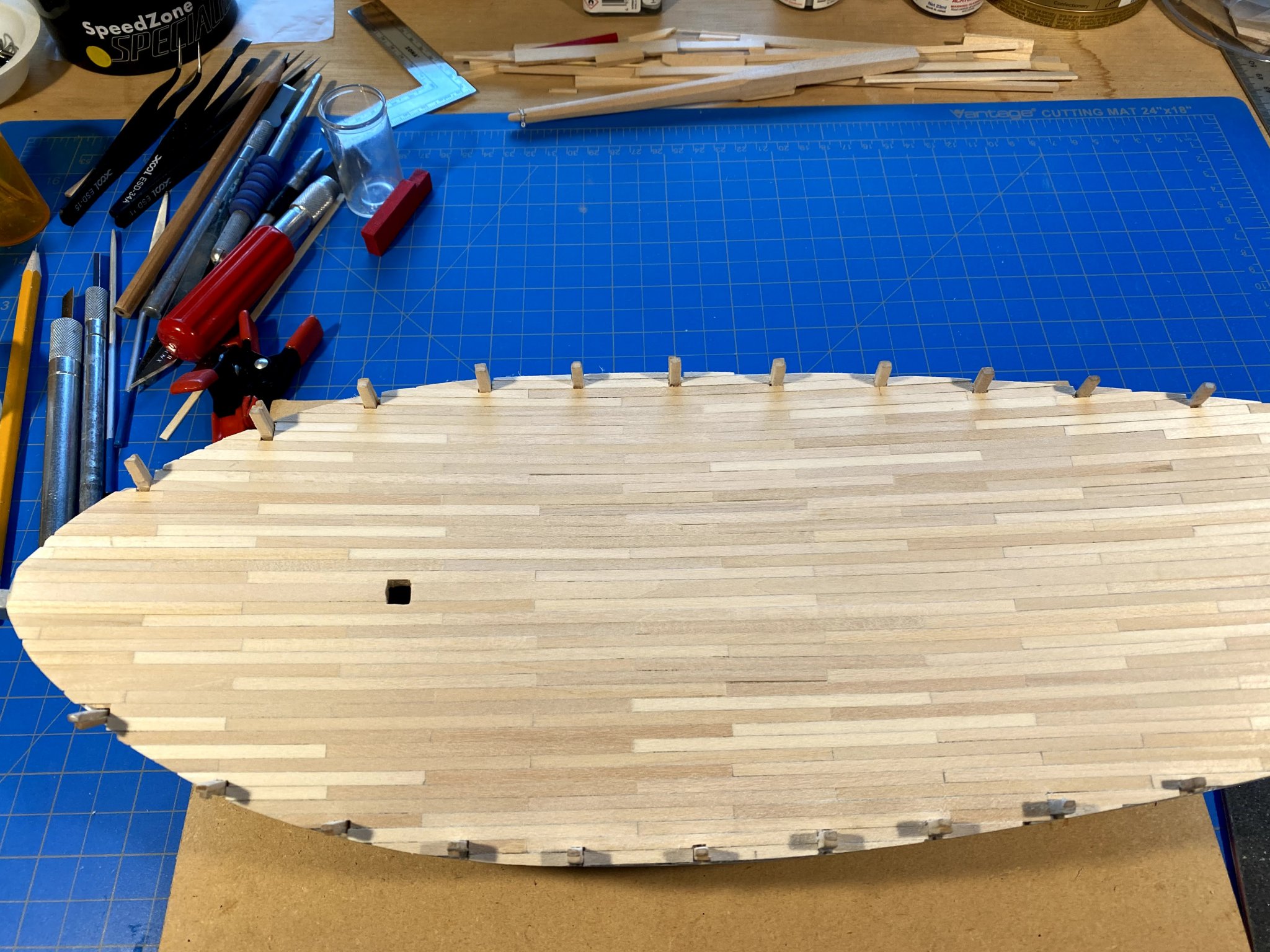
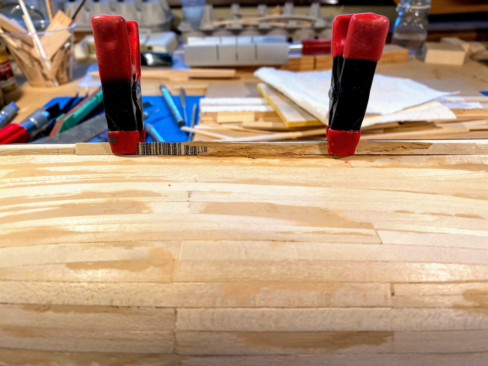
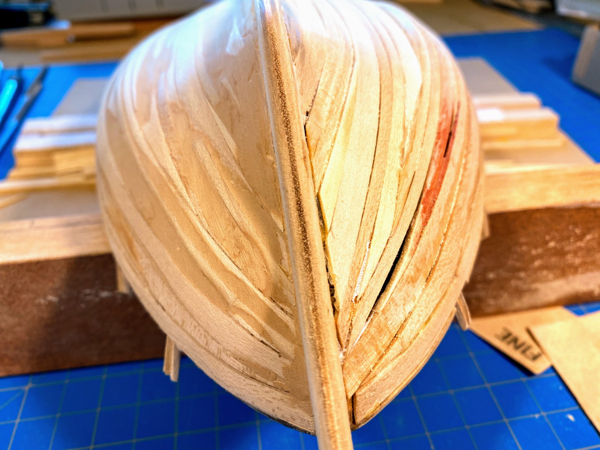
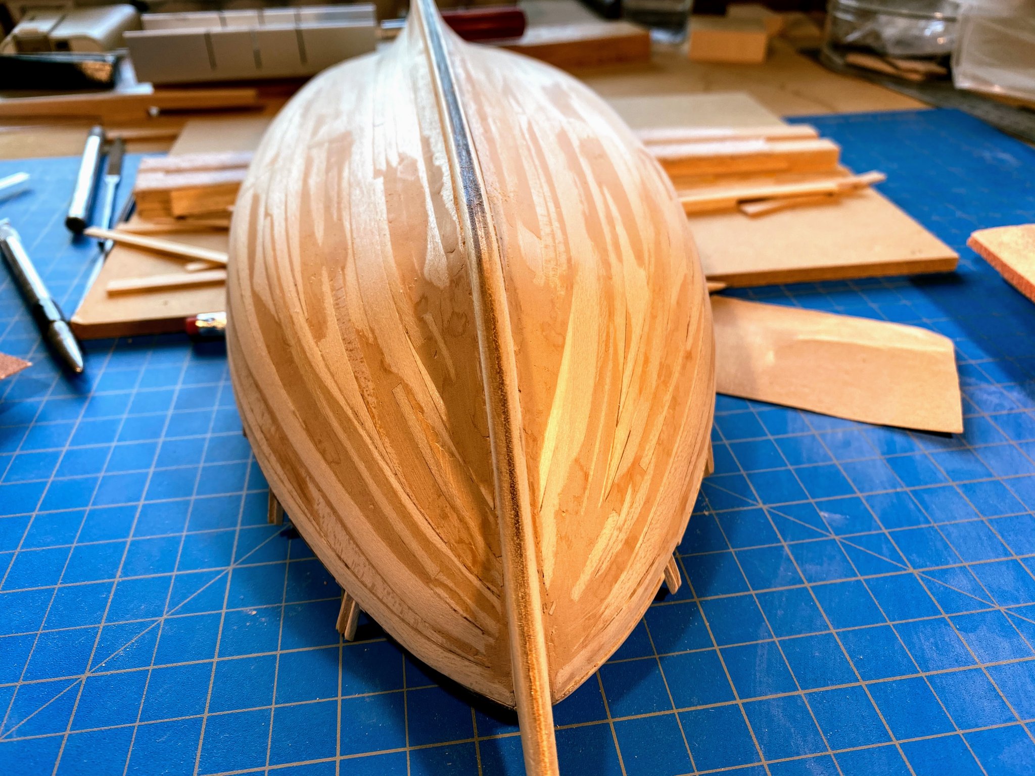
Another six weeks since my last post, and some real progress made on the hull. Wood filler saved the day. Here is where I was a couple of weeks ago, raw planking on one side, and filled and sanded on the other. Lemons to lemonade? Now backtracking some more. I made the decision that the 3/32” thick strips supplied with the kit would be too thick to bend very well. Supplemented with just a minimal purchase, I had enough 1/16” thick strips in my lumberyard to do the hull, and I had strips that were 3/16” wide, in addition to the 1/8” and 1/4” supplied with the kit. For the most part I liked the way the 1/16” strips bent, and I am not convinced I made a mistake deviating from the kit in this way. But then again, who am I to question the wisdom of the master model buildings and BlueJacket. Here’s the biggest problem I had. In the bow, where the hull curves in toward the centerline, I found that I couldn’t get the bottom of the planks to lie flat against the bulkheads; rather they flared out (relative to the bulkheads). The result might have been fine with lapstrake planking-- in places, the top edge of the next plank fit nicely under the bottom edge of the plank above it, but that’s not how this hull is supposed to go together. Here’s a picture that shows the problem most clearly at the bow, and a couple more which show bad portions of the hull looked mid-planking. Hard to sum up what made it all come out OK eventually, but certainly the following helped: more patience than I thought I had, a willingness to tear out planks that just weren’t going to work and replacing them with narrowing ones, and rummaging around this website for helpful articles and in particular finding Chuck Passaro’s tutorials. I found links to videos on building the Winchelsea here https://modelshipworld.com/topic/22975-chuck-passaros-planking-videos-where-are-they/ and the first three chapters of his Winchelsea monograph here https://www.syrenshipmodelcompany.com/hms-winchelsea-1764.php I recommend them highly. In addition to that, it probably would have helped if I had cut a rabbit (rabbet?) or bearding line at the stem and maybe along the keel, and if I had carved a filler block to put between the forward bulkhead and the stem would also have been helpful. To try to restate Chuck’s work here would not do it justice. Instead, I’ll only highlight one thing--how he bends planks onto the hull. It is far quicker, and a bit easier, than what I was doing. I had been soaking each wood strip in water I had brought to a boil for 20--30 minutes, then bending and clamping it onto the hull, then letting it dry for a few hours. Once thoroughly dry the plank could be removed from the hull, it would maintain its bent shape, and I would glue it in place with wood glue (being my glue of choice for almost everything; particularly Titebond). I would apply it to the bulkheads and along the edge where it would adjoin the plank already in place. In his videos, Chuck takes a dry strip of wood, wets it with his finger dipped in water, then bends it in place with a travel iron. Do take a look at the video; don’t rely on my description. I have an iron I used decades ago to apply monocoat to RC gliders, and it worked very well. Using CA instead of wood glue, he puts a drop or so on each bulkhead but none along the adjoining edge. I found that the wood did not maintain its shape when I pulled it off the hull to apply the glue, but it was still pliable enough to bend it back into shape after the glue was applied. Some clamping came in handy, and since it’s CA, if I really needed to I could hold it in place with my fingers for several seconds while the glue took effect (being careful of course that I didn’t glue my fingers to the hull!). At some point, tired of struggling with the sharp bending in the bow, I decided to install the garboard strake. Somewhere I had read that it is typically the most difficult one to install, but actually it was quite easy. It does require some significant twisting of the plank, but that is about it. To install the garboard strake though, I needed to sand something of an inset at the back of the keel; otherwise with the added width of the planks the keel would simply be too wide. Another thing I did was to not to try to make every successive plank conform to the bend in the shear plank. Rather with the third or fourth plank, I left it largely unbent in the vertical plane, which left a sizable gap in the bow (and a smaller one in the stern) which I filled with stealer planks tapered to a sharp point. I learned that such sharp points are not recommended, and they certainly wouldn’t look very good on a model with an unpainted hull, but they worked for me. Another thing I learned on this site was how to make a plank clamp out of binder clips. For my previous POB builds I took mini clips and used CA to glue a small piece of wood inside it as seen in one of the pictures above, but they sometimes broke off and just didn’t work very well. Far better to cannibalize the handles from another clip and use them instead of the wood strip. I found the handle from a “small” size binder clip fit very well in a “mini” size clip. For wood filler I have mainly used Bondo over the years (one part variety; not two part). It sands very easily and does a great job filling smaller cracks and holes. But its pungent fumes are irritating at best and probably very unhealthy, and when I started using it on this hull the weather wasn’t conducive to opening the windows. So I switched to Elmer’s Carpenter’s WoodFiller, which worked pretty well, especially filling large voids. So here it is, pretty much ready for a first coat of primer. A discerning eye examining the real thing will find a dip or bulge or two that don’t belong there, but on the whole I’m pretty happy with it. I’m ready to paint a coat or two of primer and move on to other challenges.


- 82 replies
-
- 2
-
-
- spray
- BlueJacket Shipcrafters
- (and 1 more)
-
Great work! Also, for me, it's nice to have someone doing the same build I'm doing but several steps ahead. I haven't added to my blog in quite a while, and probably won't until I get the hull fully planked and at least one coat of paint on. I'd always rather build than write. The hull planking has been a bit of a struggle, but I got the final pieces in place yesterday, and the considerable amount of needed wood filler and sanding has begun, and so far has gone a bit better than expected, so overall I'm still pleased with the build. Keep the posts coming. 🙂
- 29 replies
-
- 1
-
-
- spray
- BlueJacket Shipcrafters
- (and 2 more)
-
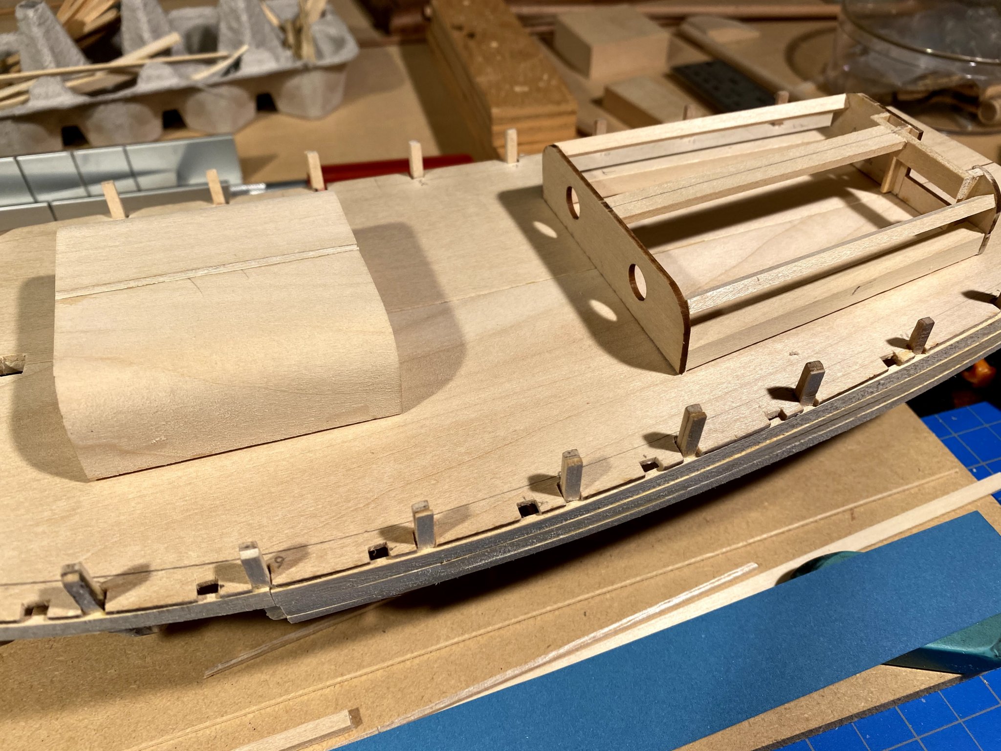
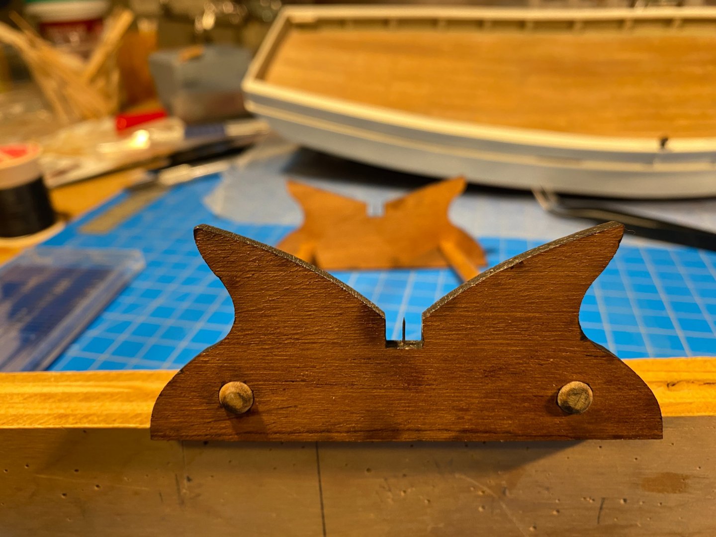
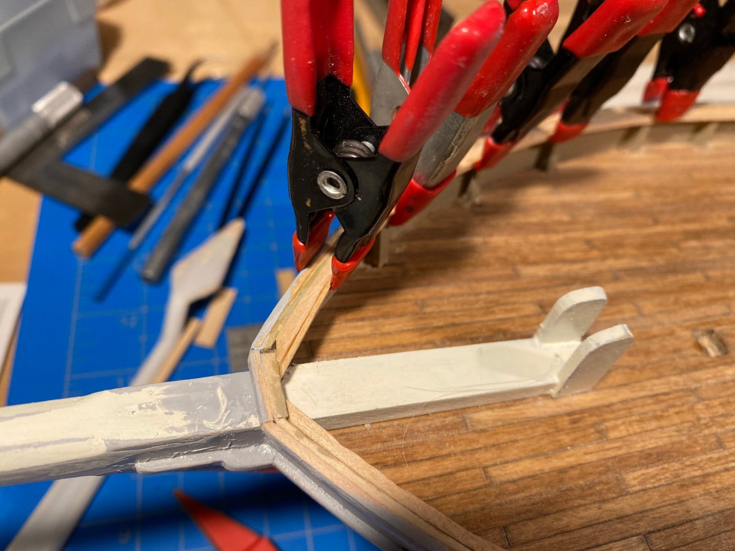
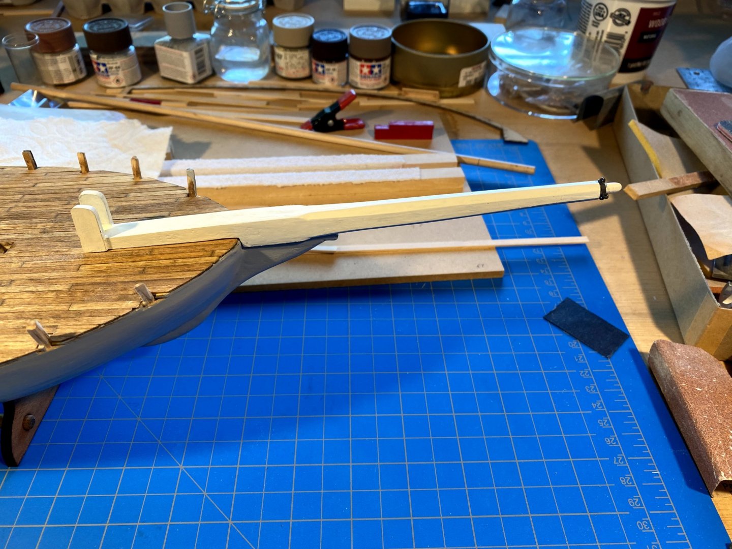
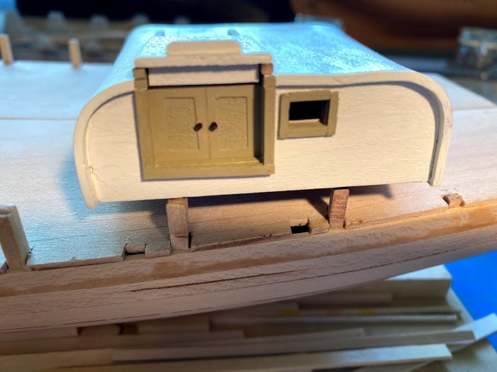
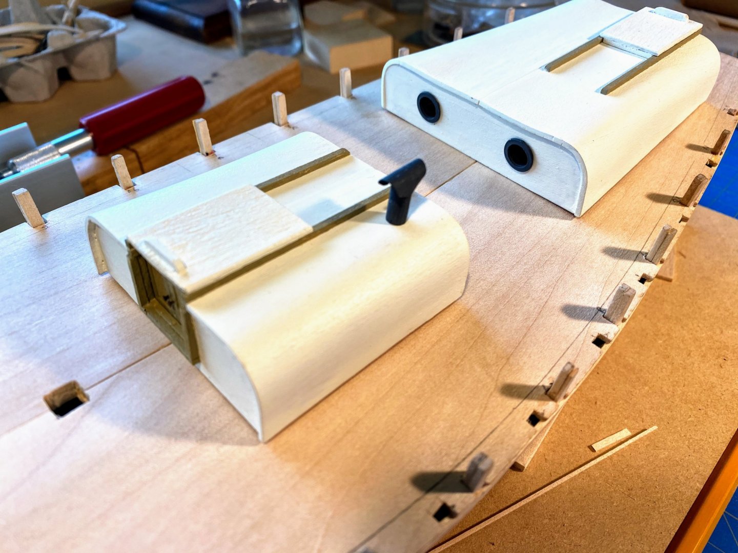
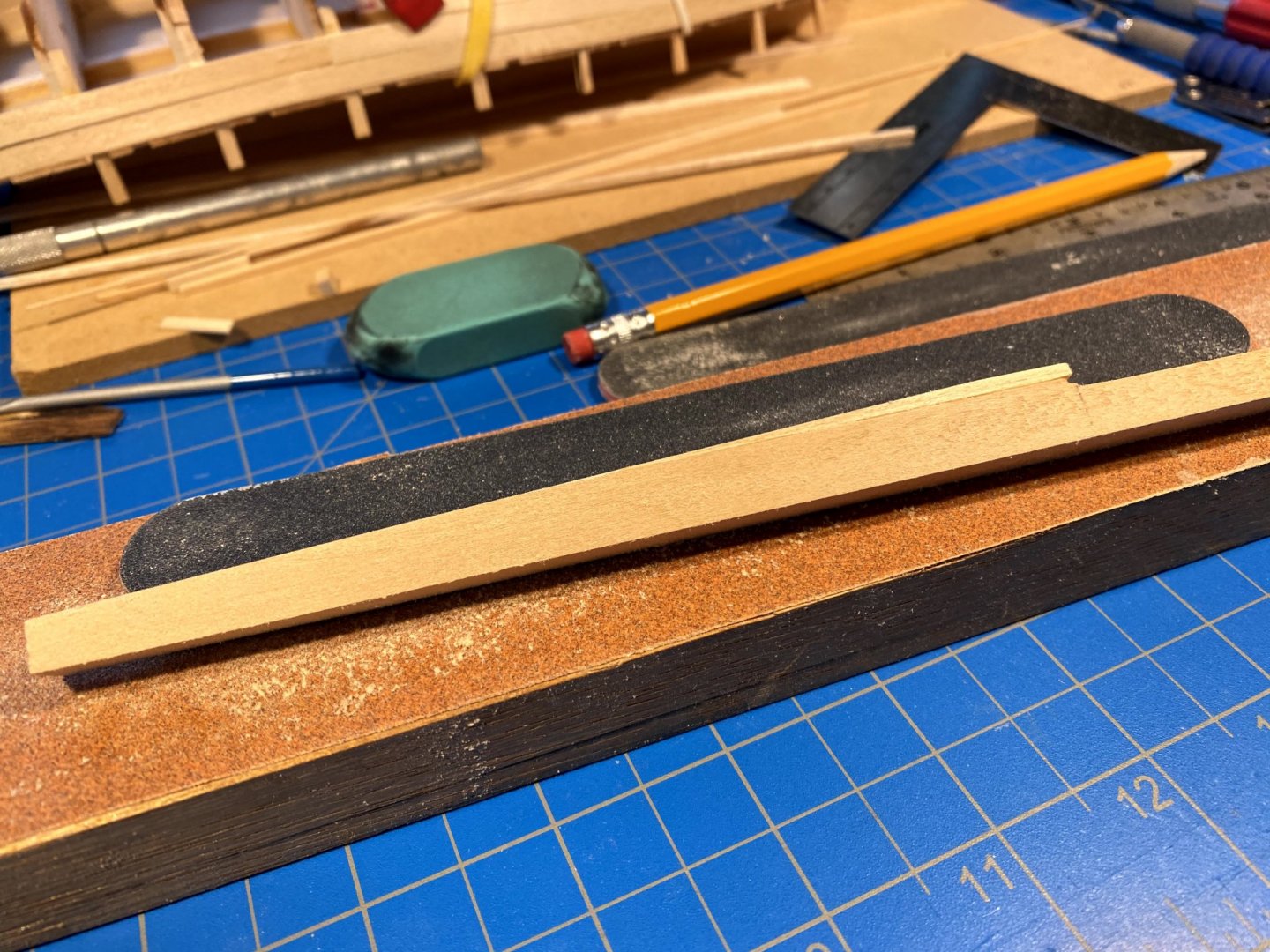
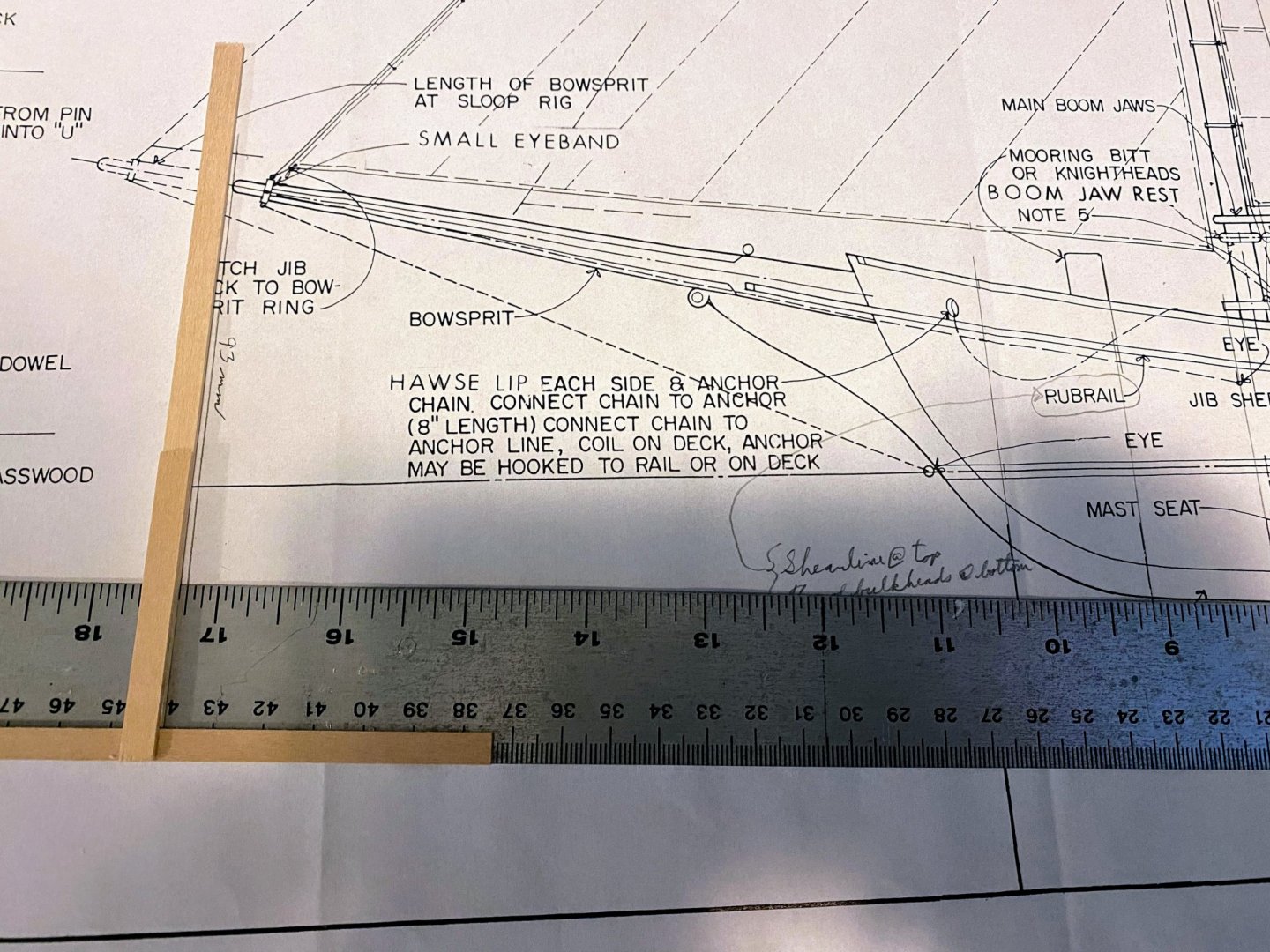
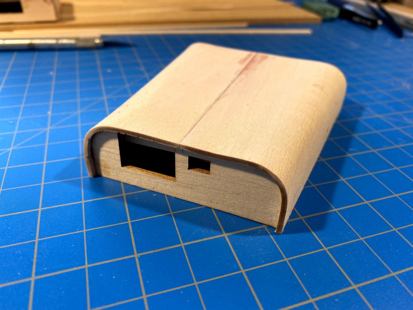
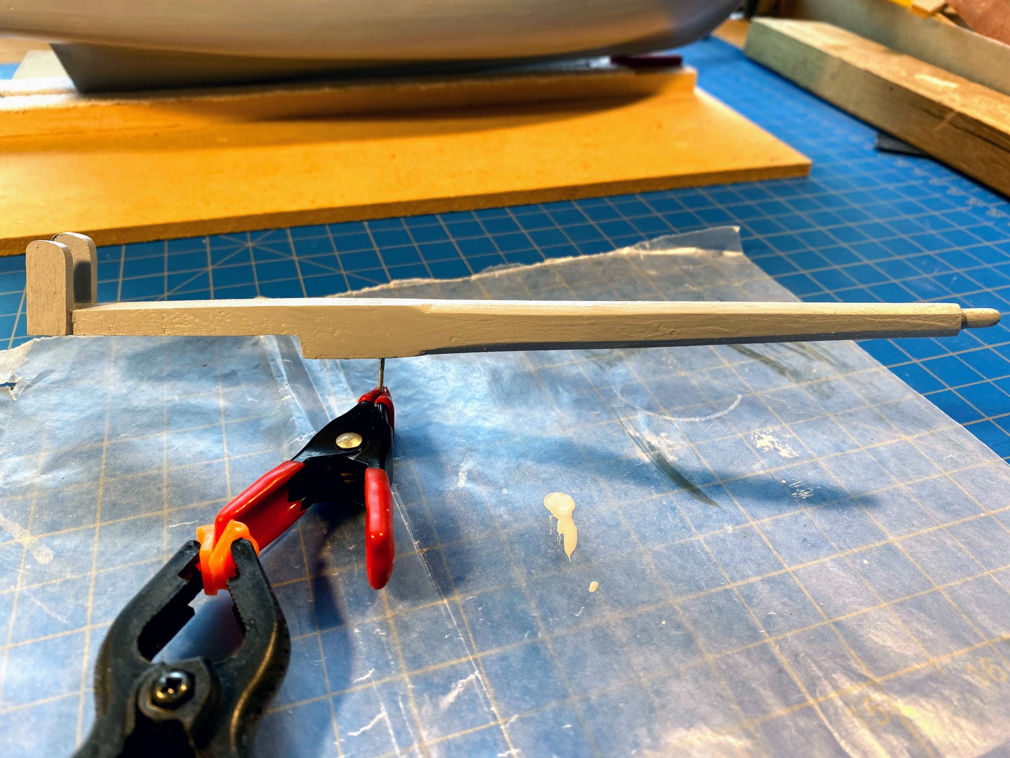
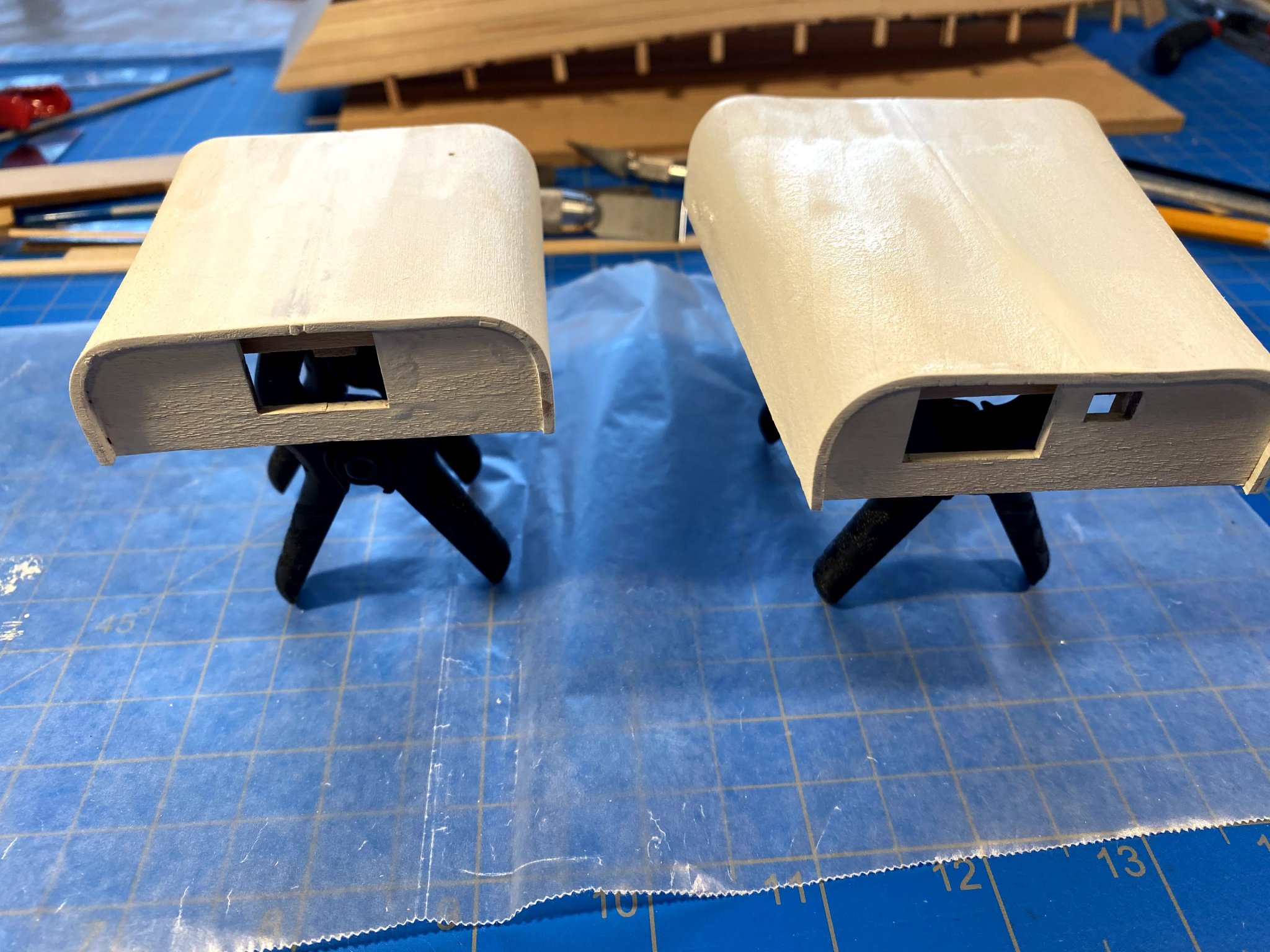
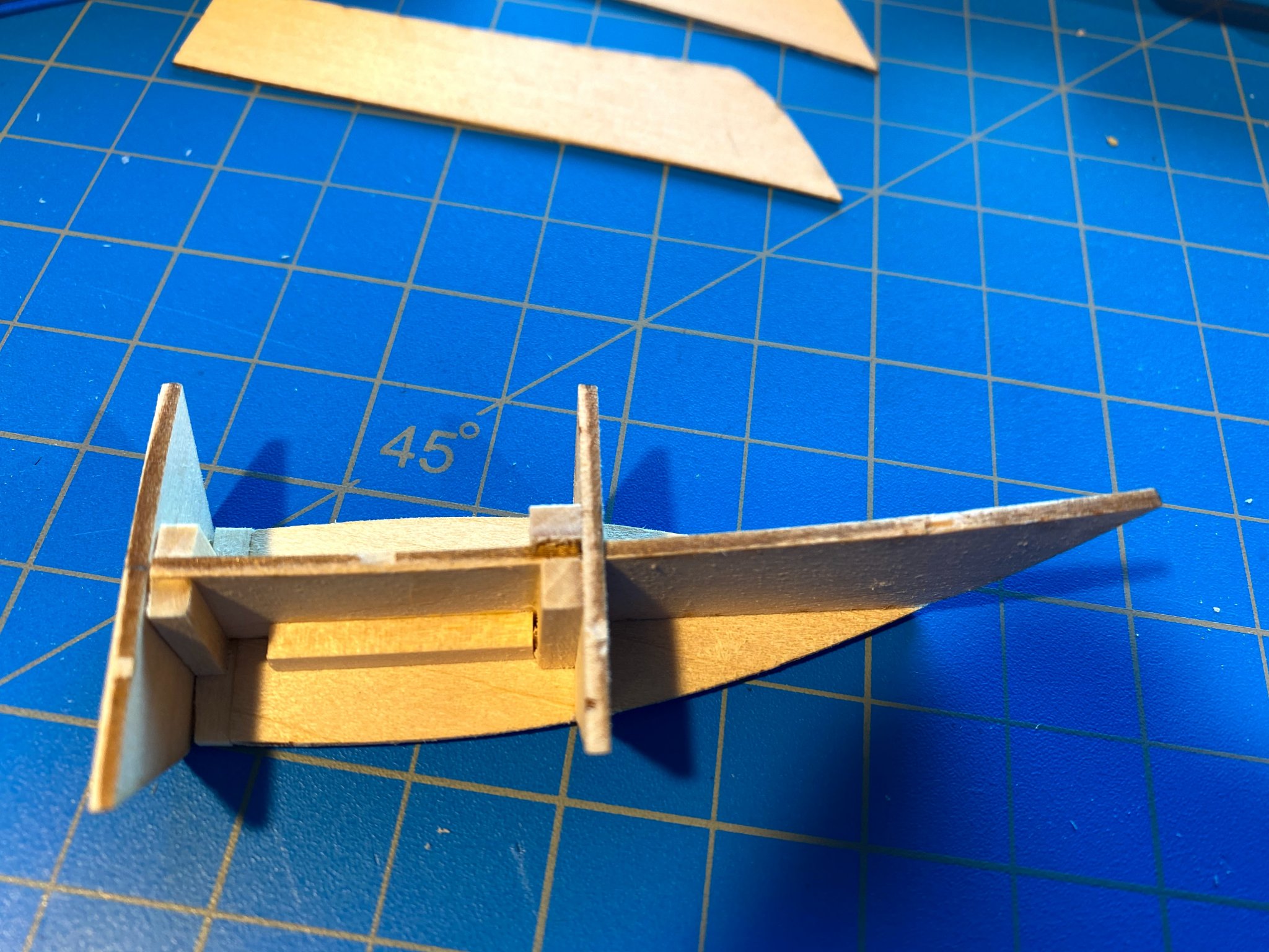
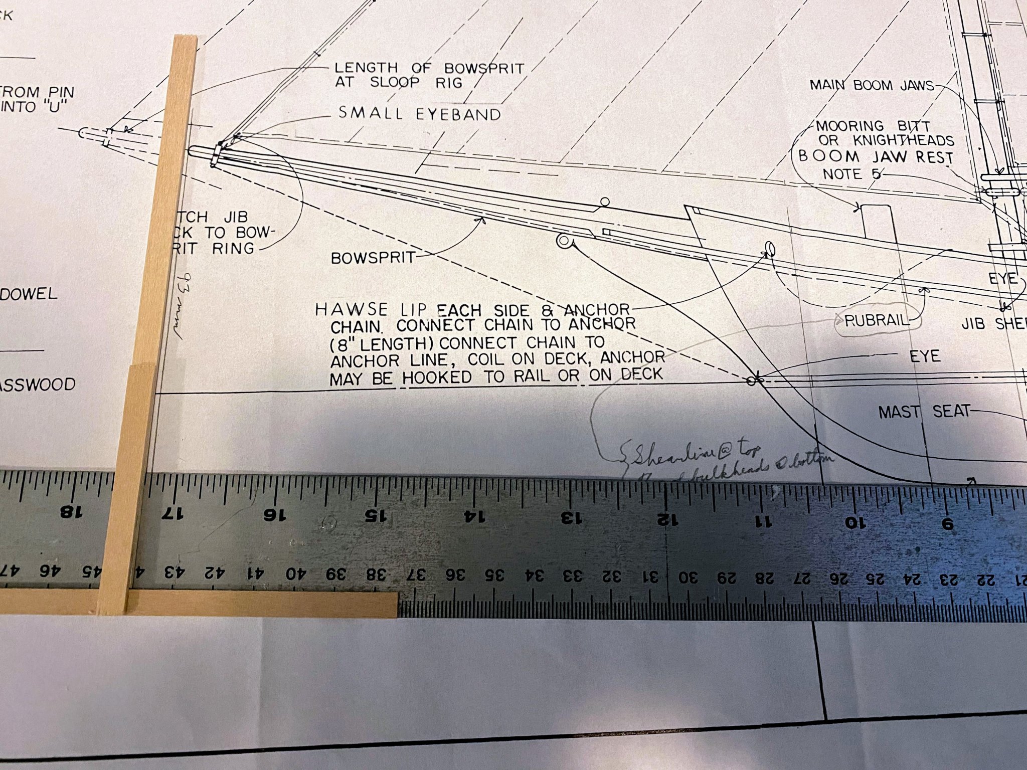
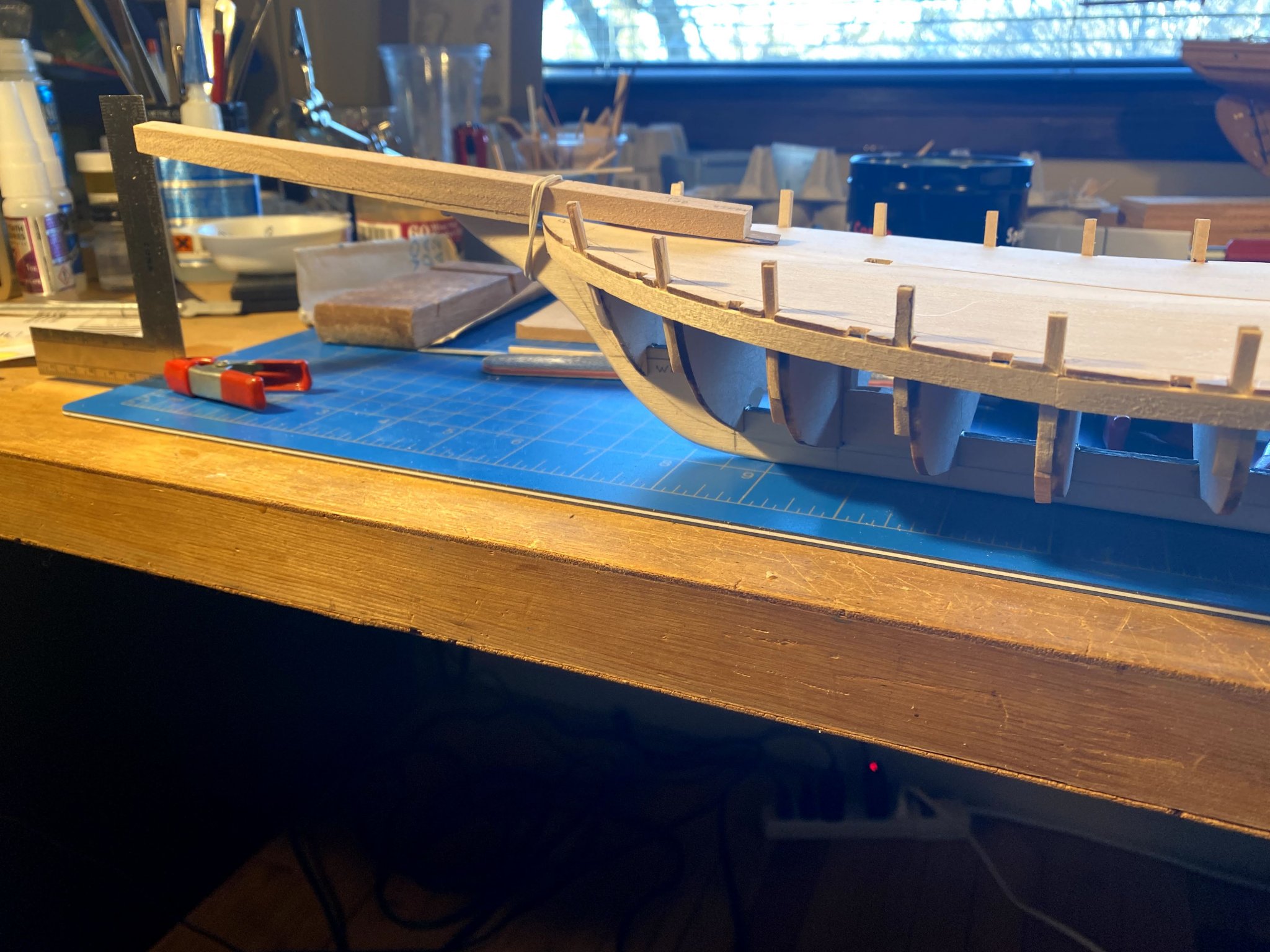
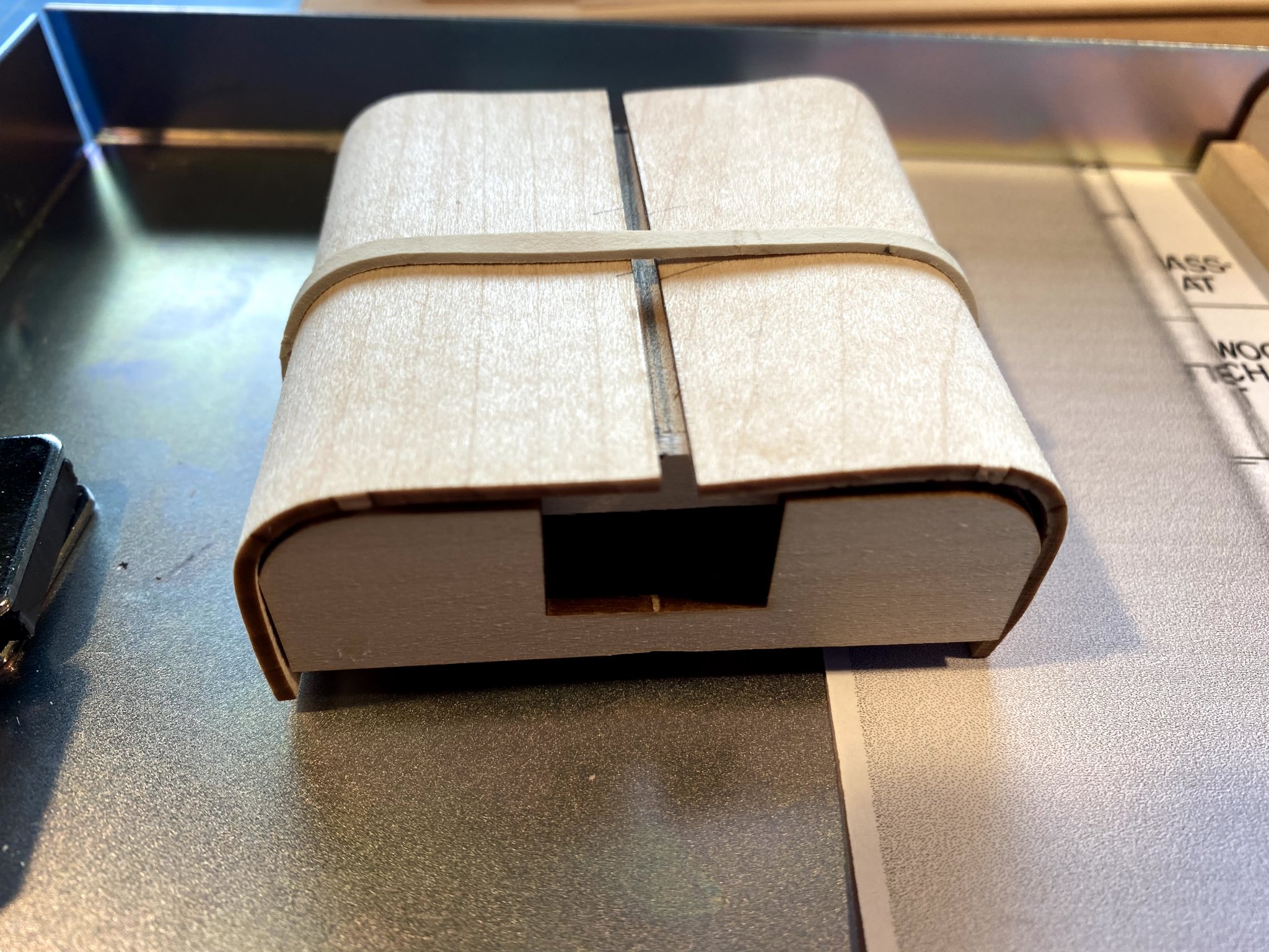
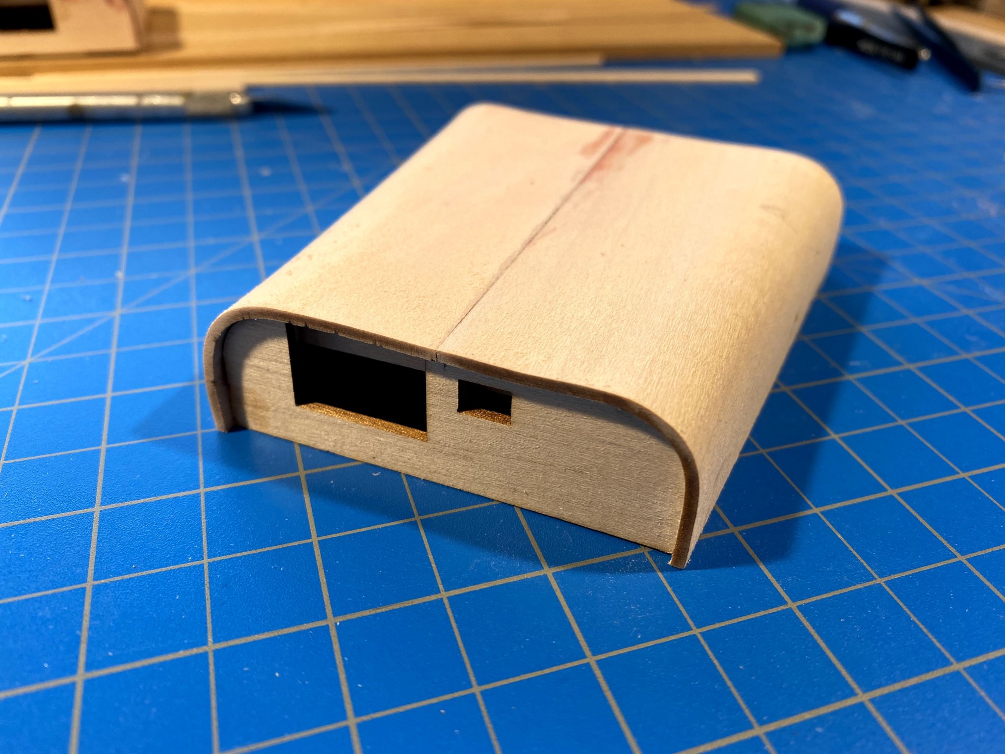
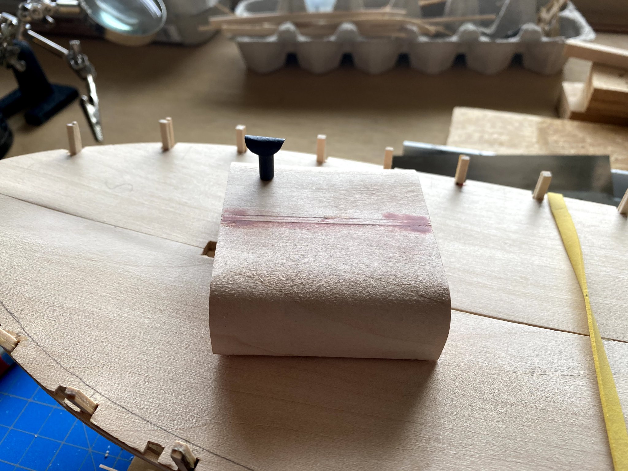
My how the world has changed since I last posted, on March 1. Confined to our home you’d think I’d get more done than usual on my build, but working from home part time seems to take as much time as working near full time in the office. And since that’s all I really have to complain about, I’m feeling very fortunate. Installing the sheer strakes went quite well, but the next two were a different story, in the bow anyway. I ended up tearing out the front half of strakes two and three after they were glued in place, and I have been taking a different approach that (so far) is working much better. No pictures yet (who likes to show off their mistakes?), but if things go well my next post will be all about planking, with photos. Meanwhile, planking has a lot of downtime while planks soak, then dry in place, then while the glue dries. So I’ve been jumping ahead to other build projects. First, the bowsprit. The kit supplies a ⅜ by ½ piece to shape the bowsprit from, but when lining that up on the plans, I noticed that only a small portion extends beyond ⅜ by ⅜. Not liking to sand and carve any more than I have to, and having an extra ⅜ by ⅜ strip in my lumber yard of sufficient length, I glued a 3½ inch long ⅛ by ⅜ strip onto the bottom of that piece of wood, making the notch shown in the plans. I used rubber cement to glue a strip of sandpaper onto a 1 by 2 foot long piece of wood, which made a great sanding block for tapering the bowsprit. Here it is after a little sanding of the bottom of the bowsprit. Cutting to the appropriate length what was to become the bowsprit committed me to an important decision that I found pretty easy to make. Slocum embarked on his journey with Spray rigged as a sloop. But in South America, he rerigged it as a yawl, shortening the bowsprit and the boom, and adding a mizzen. Since most of his voyage Spray was rigged as a yawl, and since it’s almost always depicted as such in the photos and drawings I have seen, I decided to build it as a yawl. The plans though give you the dimensions you need to rig it as a sloop if that is preferred. As I sanded a bit aft of the notch, I measured the height of what will eventually be the forward end of the bowsprit, as measured from an extension of the keel (rather than the waterline). I got it within a few millimeters, which should certainly be good enough for now. Once the deck is installed I can make final adjustments. I sanded rather than carved the forward taper (which doesn’t show up very well in this picture; don't know why the knives are there), where the bowsprit is octagonal in cross section. I guess I just don’t trust myself with a knife-- too easy to overdo it. I still need to taper it a bit more, but it’s close to finished forward of the notch. Next project was the deckhouses. I attached the two laser-cut end pieces to each other with scrap strips of various sizes, in order to build a rigid frame around which to bend the roof/walls. Starting with the smaller, forward cabin, I first glued the two roof pieces to each other, then soaked them in hot water for about half an hour. I then carefully, slowly, bent the roof around the frame, until CRACK! The roof pieces split apart where they had been glued. I nevertheless continued with bending the two pieces to the appropriate shape, let them dry, glued them in place, and ended up with about a ⅛ inch gap, easy enough to fill some scraps strips of wood. The aft cabin is narrower aft than forward, which made the bending of the soaked roof a little tricky. This time the roof held together, but apparently I didn’t use sufficient glue when assembling the frame, and a couple of the stringers broke loose as I was bending the roof. Eventually I got it all put together, used a variety of clamps to hold it while gluing, and was happy with the final product. Finally, I put together the stovepipe, using a short dowel and heavy paper for the cap. For the latter, I tried cutting a circle out of stock from a manila folder, but that was too thick -- it tended to fold rather than bend in a nice half circle. Construction paper worked just fine. I used the corners of a small clamp to hold it bent around the dowel, then painted it, and as I hoped the paint made it retain its shape. It was then easy to glue it to the dowel with a couple of tiny dabs of glue. Now back to planking the hull.

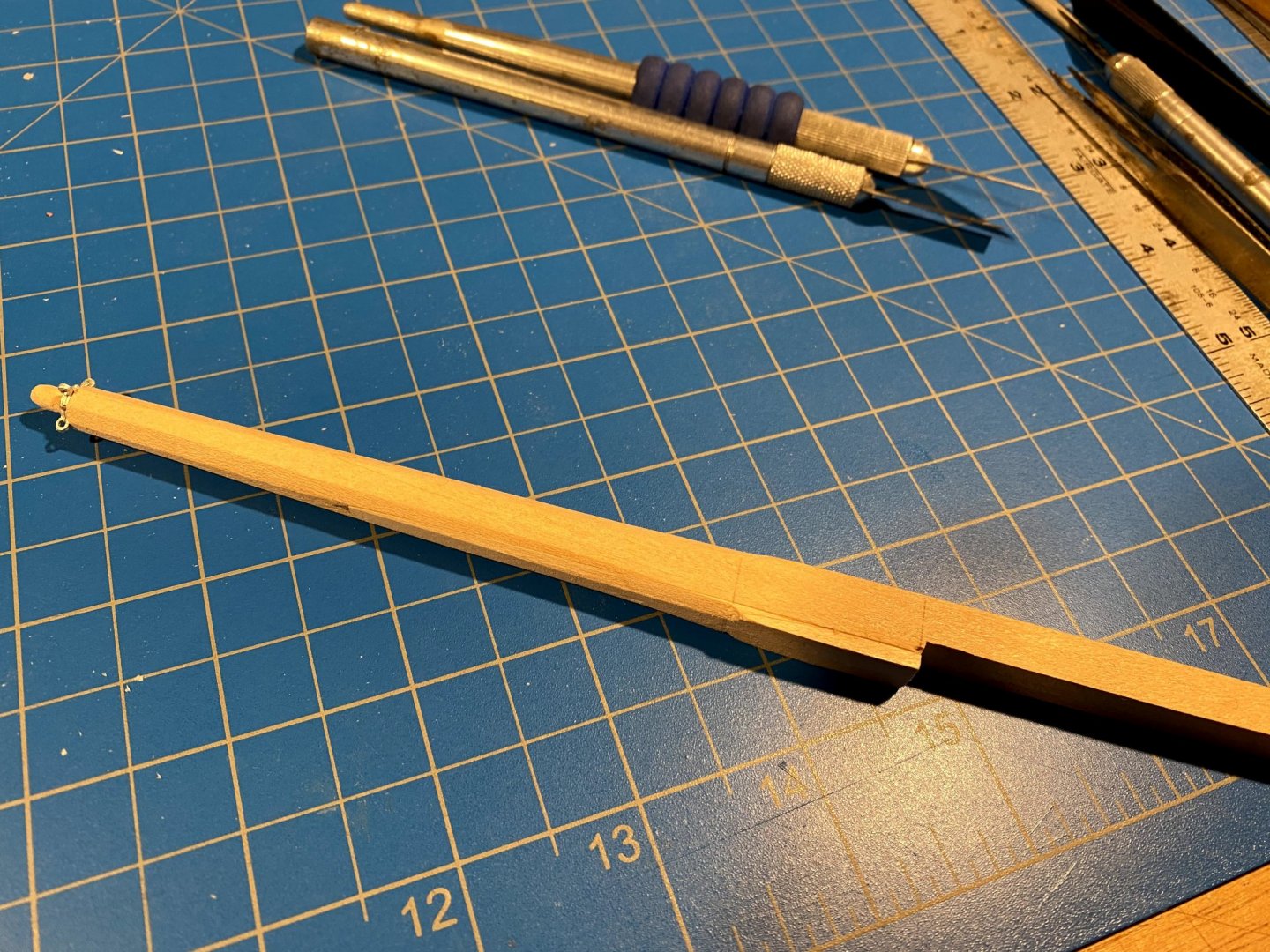


.thumb.jpg.7637062aae3022adfd0b1ba330ce139e.jpg)
- 82 replies
-
- 3
-
-
- spray
- BlueJacket Shipcrafters
- (and 1 more)
-
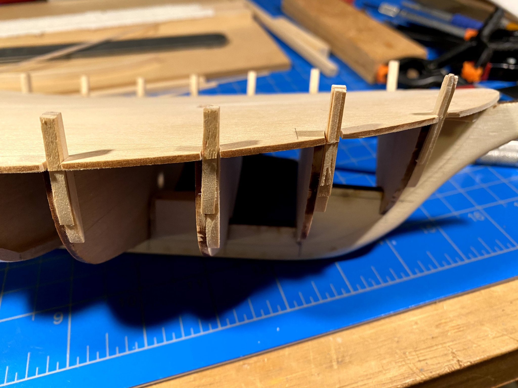
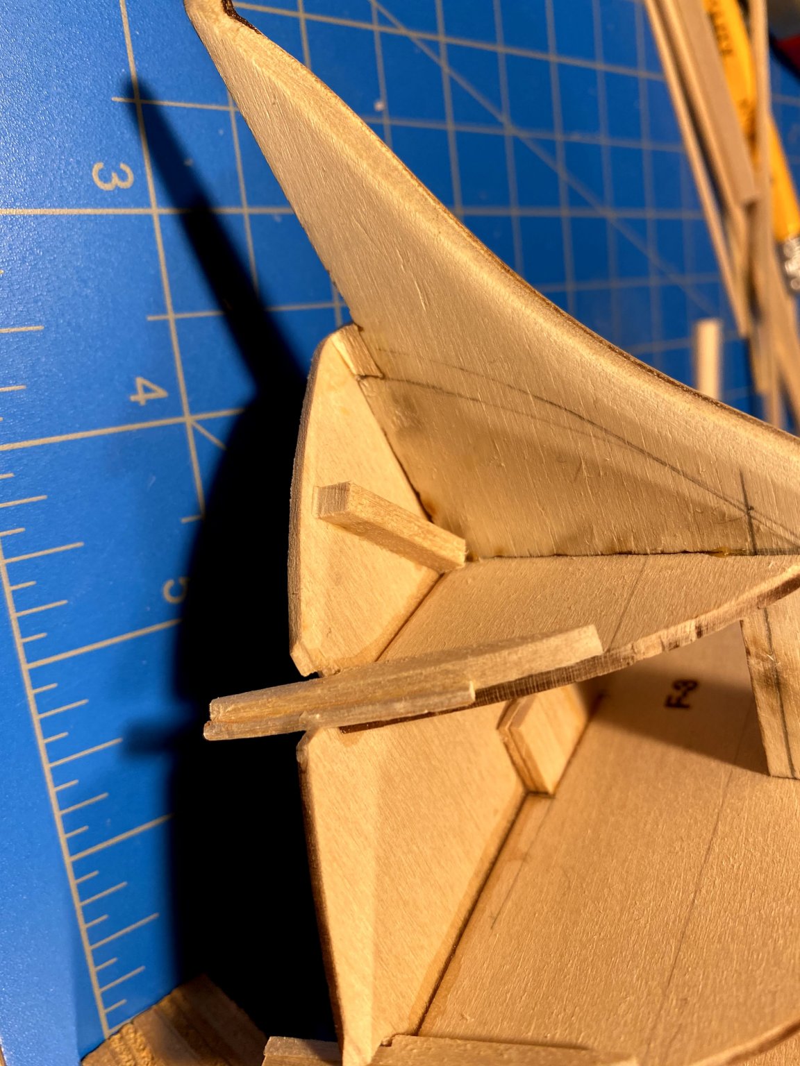
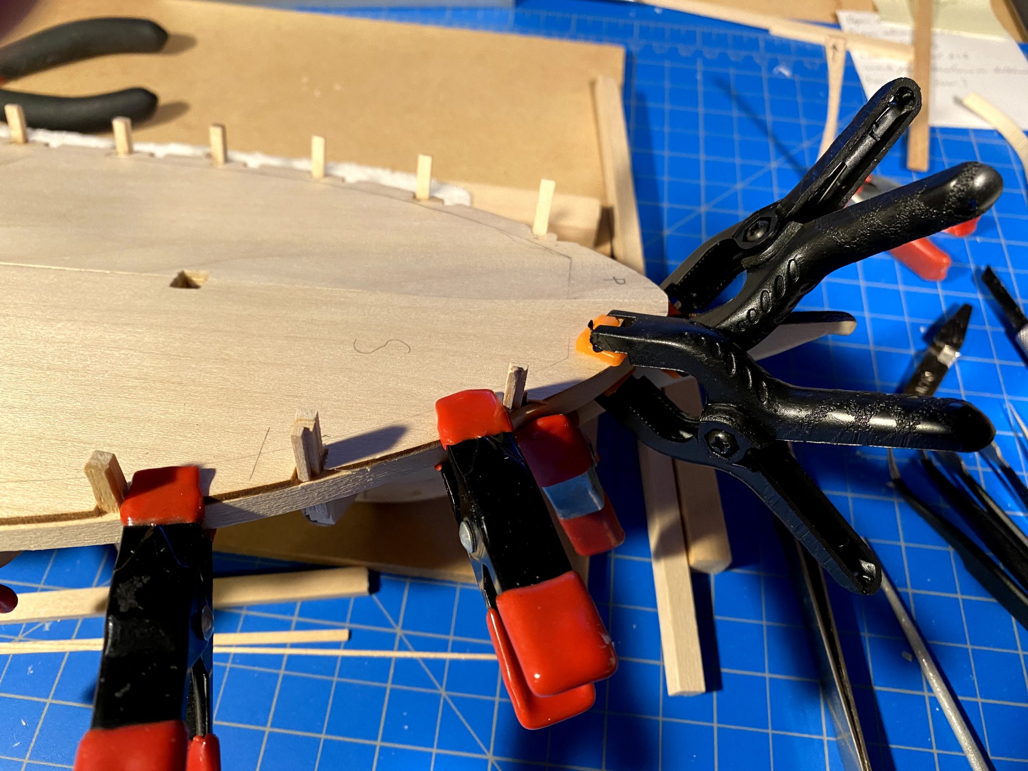
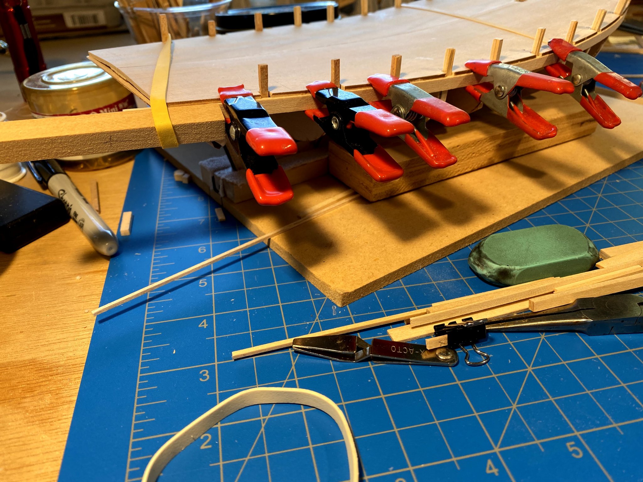
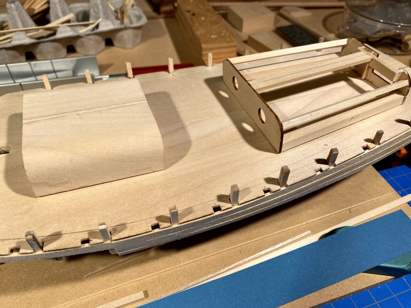
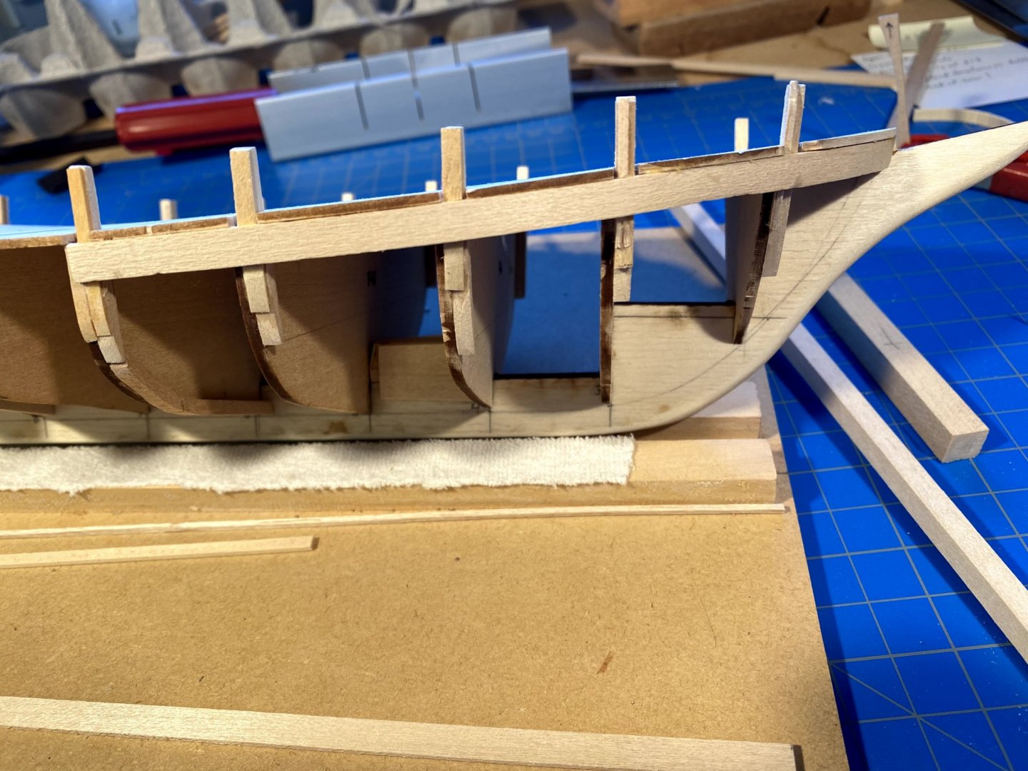
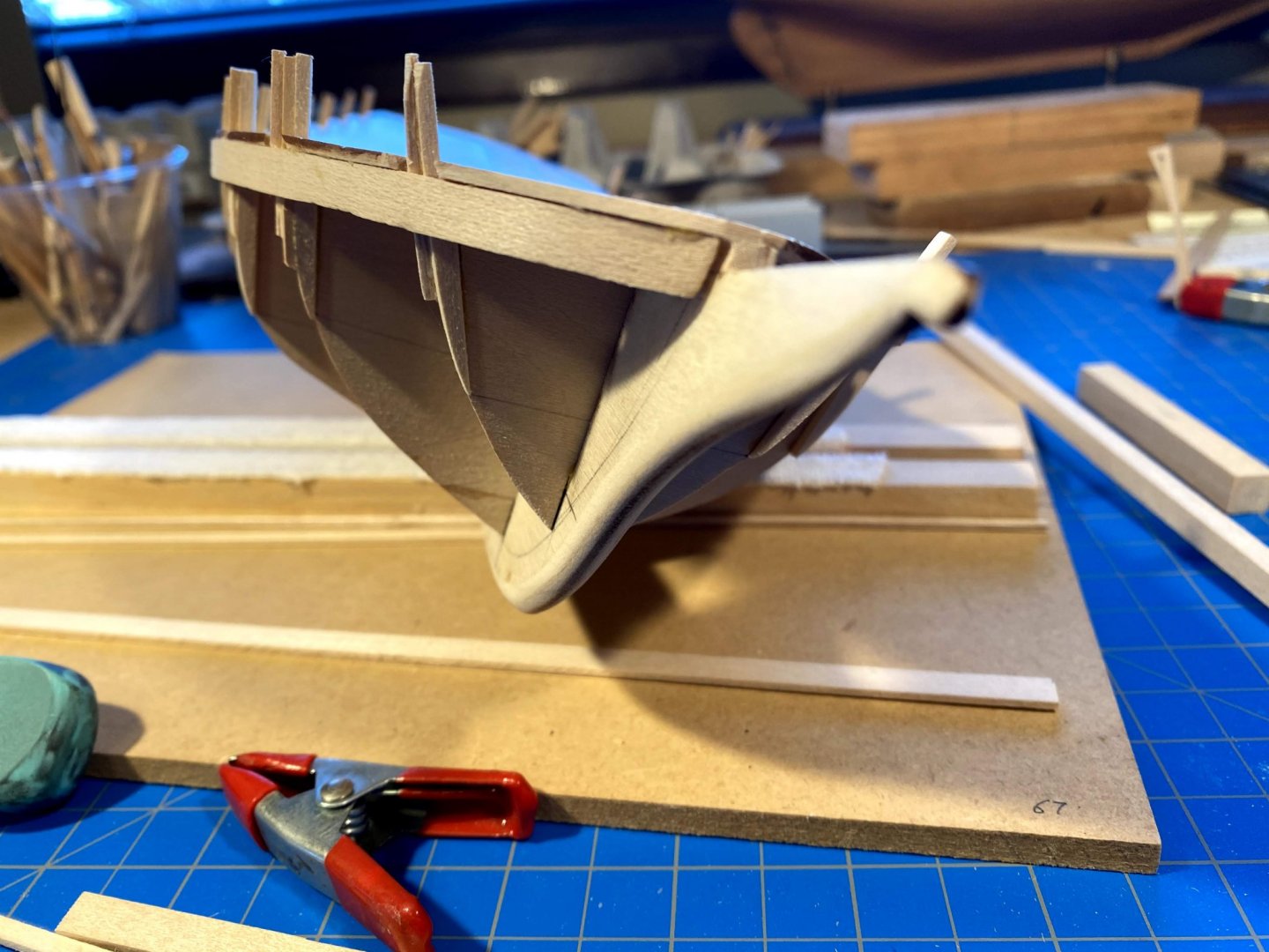
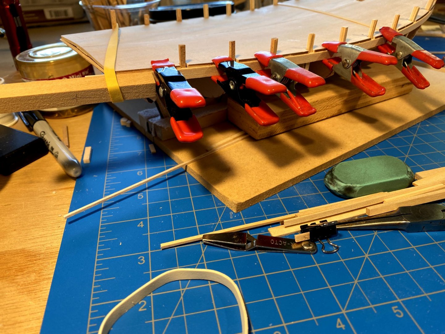
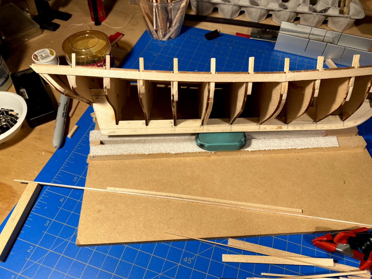
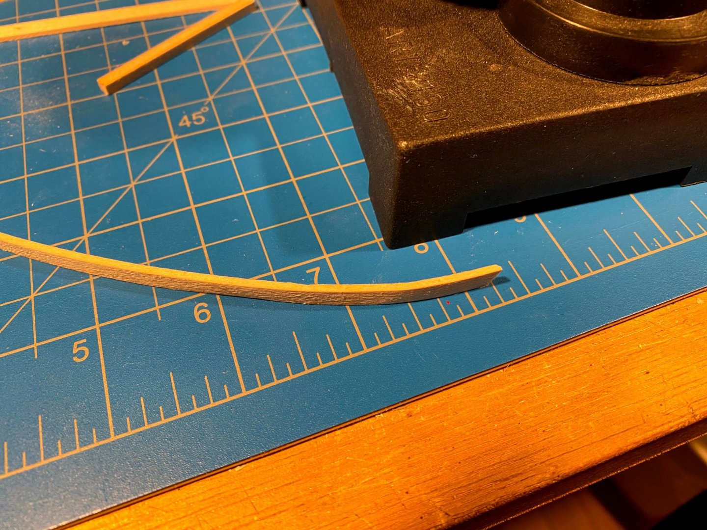
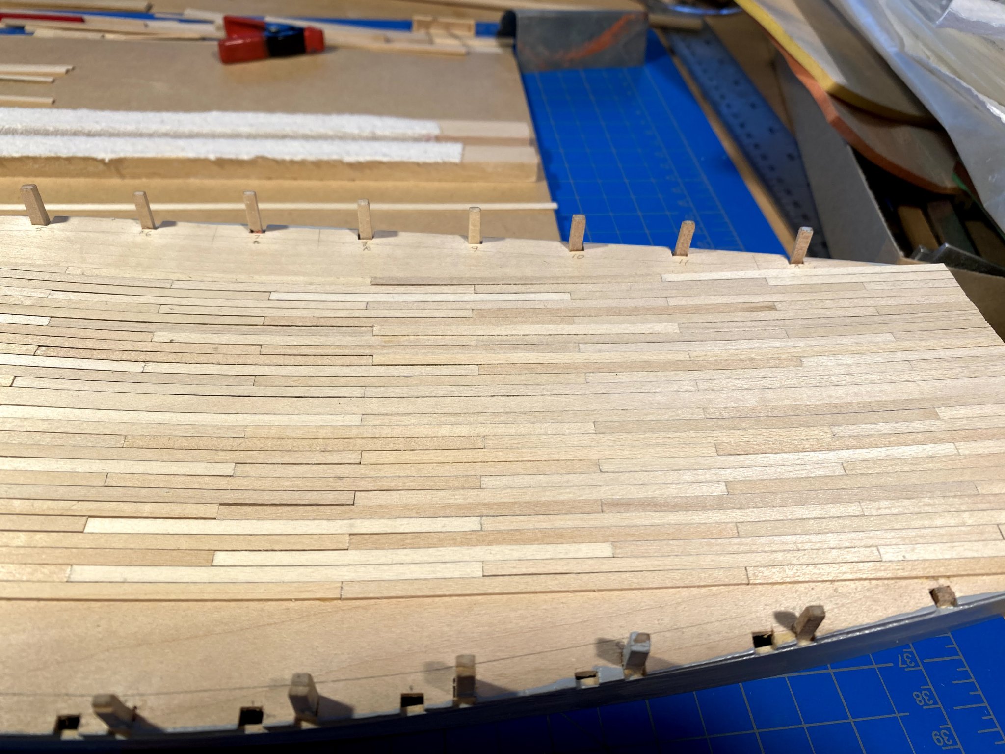
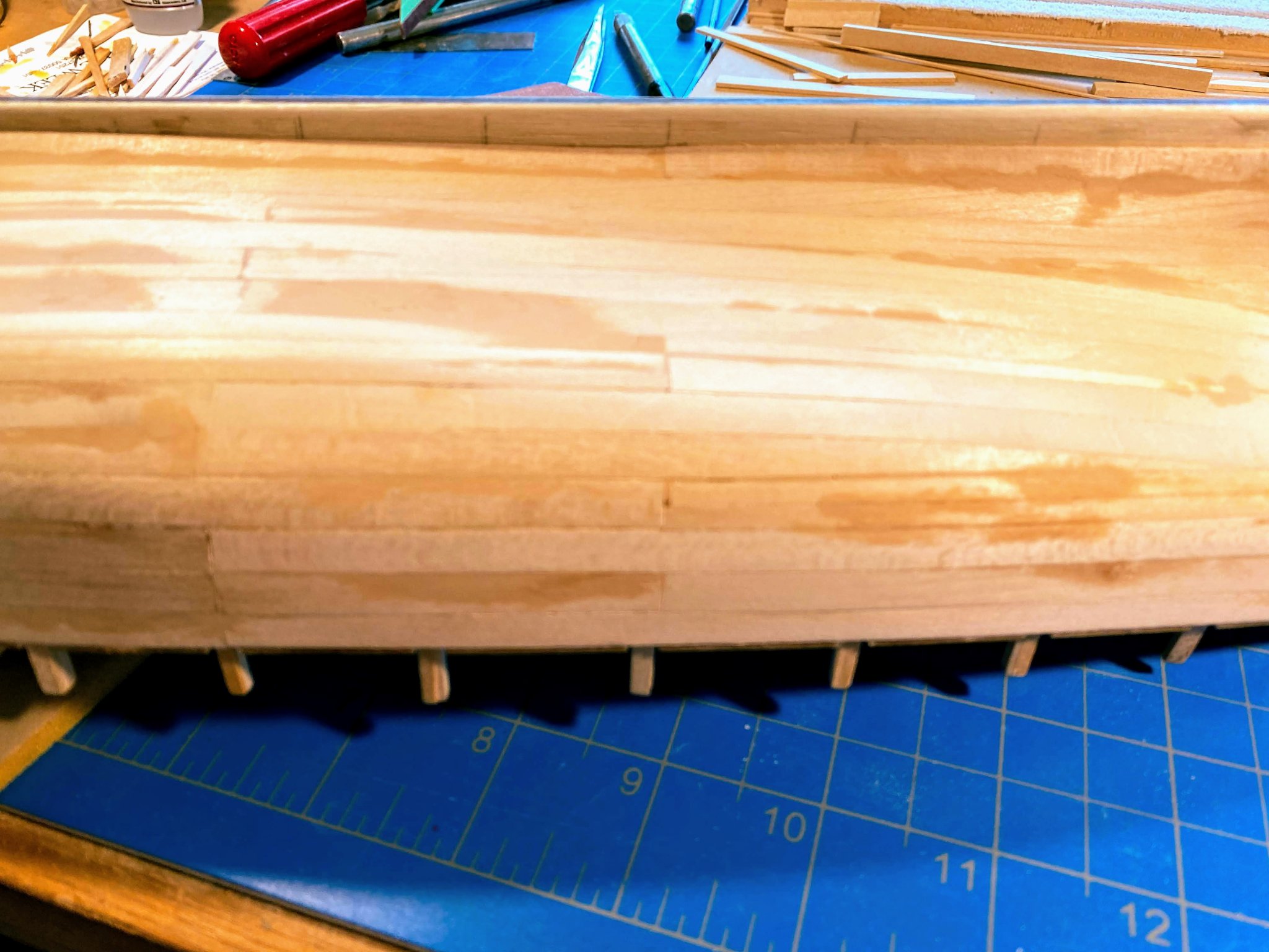
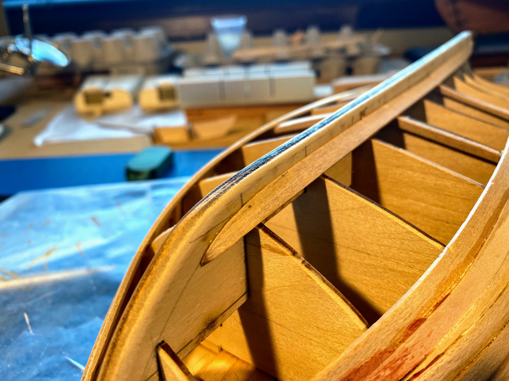
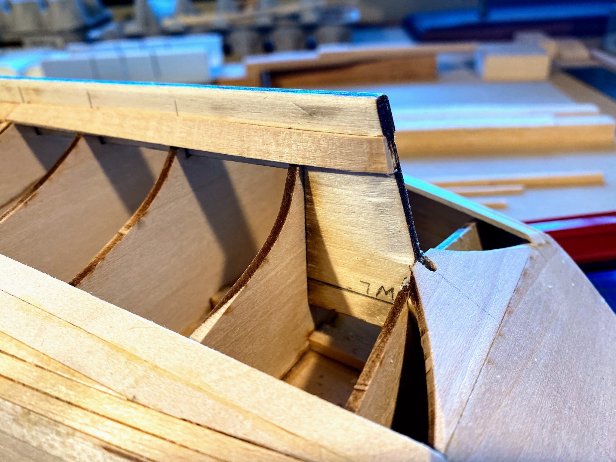
Some delightful travel and a temporary flareup of lower back issues have delayed progress a bit, but things have moved along enough now to justify another posting. First thing was some checking for symmetry, especially at the bow. Recall that the two subdeck pieces needed some trimming, one especially, and the two do not quite meet on the center line. Then came quite a bit of work beveling and fairing the stanchions and bulkheads. Especially forward the stanchions needed some shims, in addition to the usual sanding. I decided to do only what was needed for the first strake or two on the starboard side, see how well the planks bent to the shape of the hull, and then work on faring further down as strakes went in place. Alternating between port and starboard sides, of course. The bend between the forward most bulkhead and the stem is pretty dramatic, so I added something for the plank to bend around. After trimming the first plank where it meets the stem, I soaked it for about 15 minutes in the tube shown in my prior post, in water I had brought almost to a boil. I then clamped the wood in place. It bent to shape pretty easily. After letting it dry for an hour or so, I unclamped it, and had a nicely pre-bent piece of wood ready to glue in place. However, at the bow where the bend is pretty radical, rather than nicely curve around the extra piece I added, it looked more like a fold. For some reason I didn't take a picture of it. But I remembered having bought a plank bender some decades ago, and I managed to find it. I re-soaked the forward couple of inches of the plank, bent the fold around what seemed like the appropriate diameter drum, and ended up with a pretty nice looking plank, which I clamped and glued in place. A few hours later I removed the clamps and voila . . . half a sheer strake! Only problem though was that with a collection of clamps forward, I didn't notice that I didn't quite get the plank glued to the stem, leaving a small gap. A little filler, and maybe even a thin strip of wood, should take care of that problem. Now on to the stern half of the sheer strake. The bulkheads needed some beveling and sanding, but nothing like what was needed forward. Here I was able to clamp a plank in place pretty easily without soaking the wood, so I skipped that step. Sand, bevel, glue, clamp, wait, and a few hours later . . . one complete sheer strake. Got a lot on my plate the next several weeks, so it will likely be a month or more before I've made enough additional progress to justify another posting. And that's not likely to be anything more than pictures of a couple more strakes. Progress is slow, but I'm in no hurry, and most important, I'm really enjoying the journey.


- 82 replies
-
- 4
-
-
- spray
- BlueJacket Shipcrafters
- (and 1 more)
-
Contrary to what you posted on my blog, your build looks every bit as good, probably better, than mine. You're certainly farther along. I look forward to following and learning from your progress.
- 29 replies
-
- 2
-
-
- spray
- BlueJacket Shipcrafters
- (and 2 more)
-
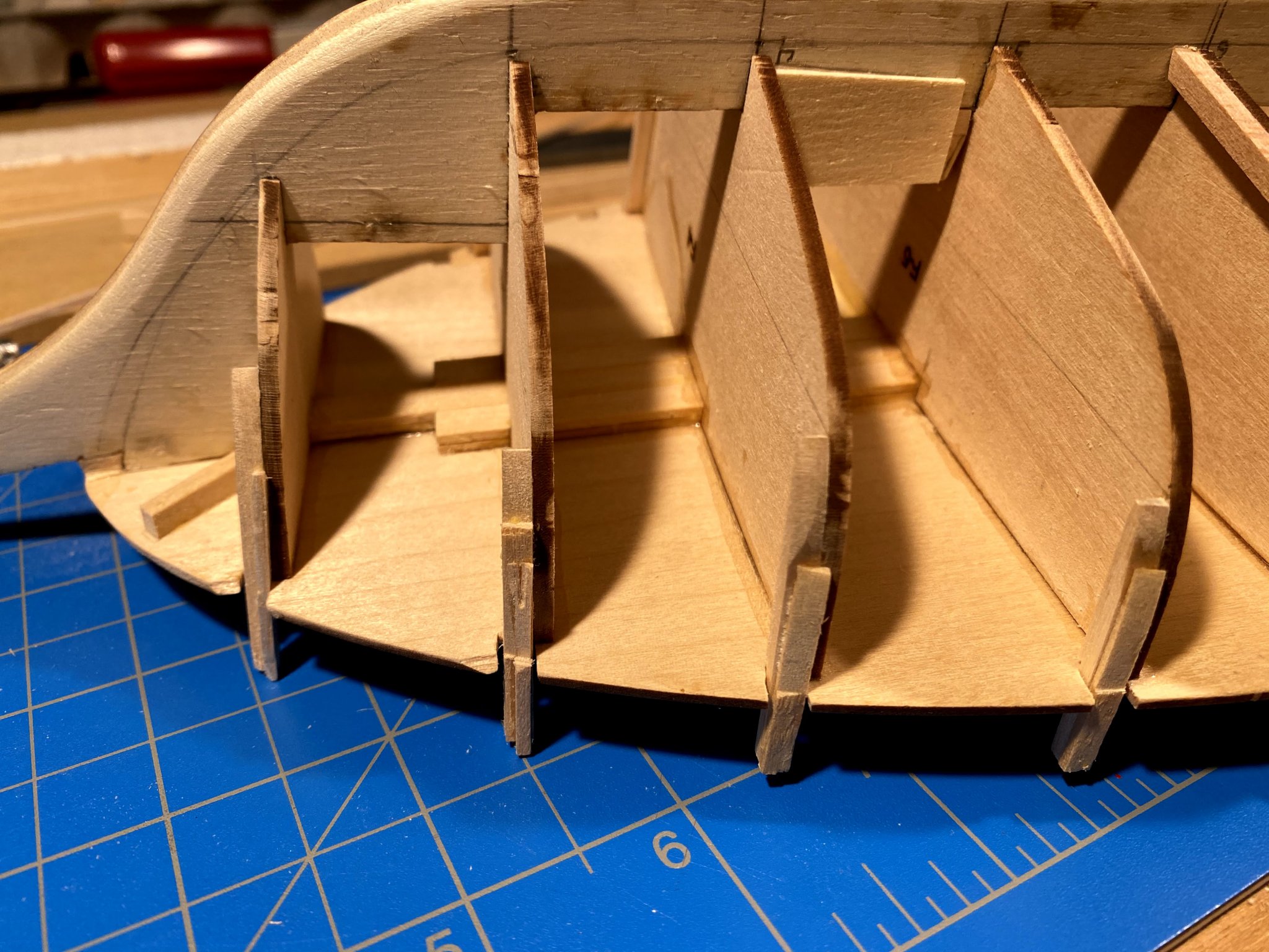
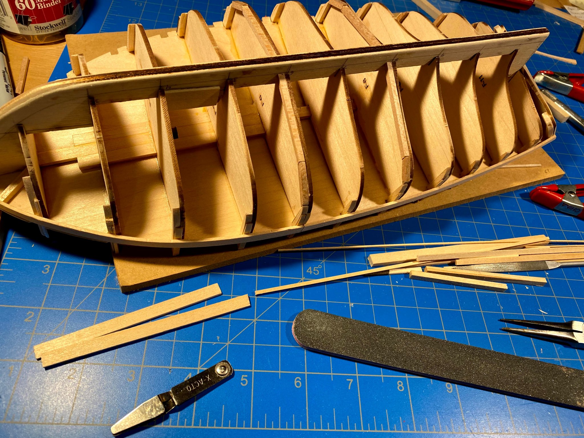
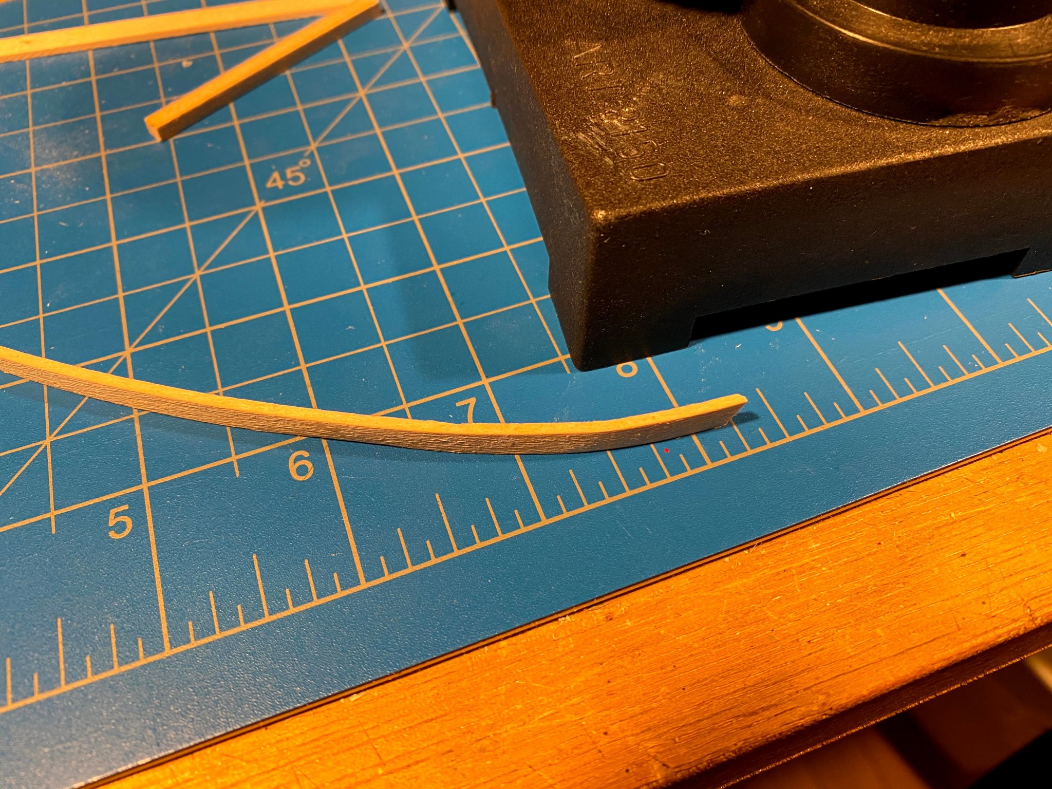
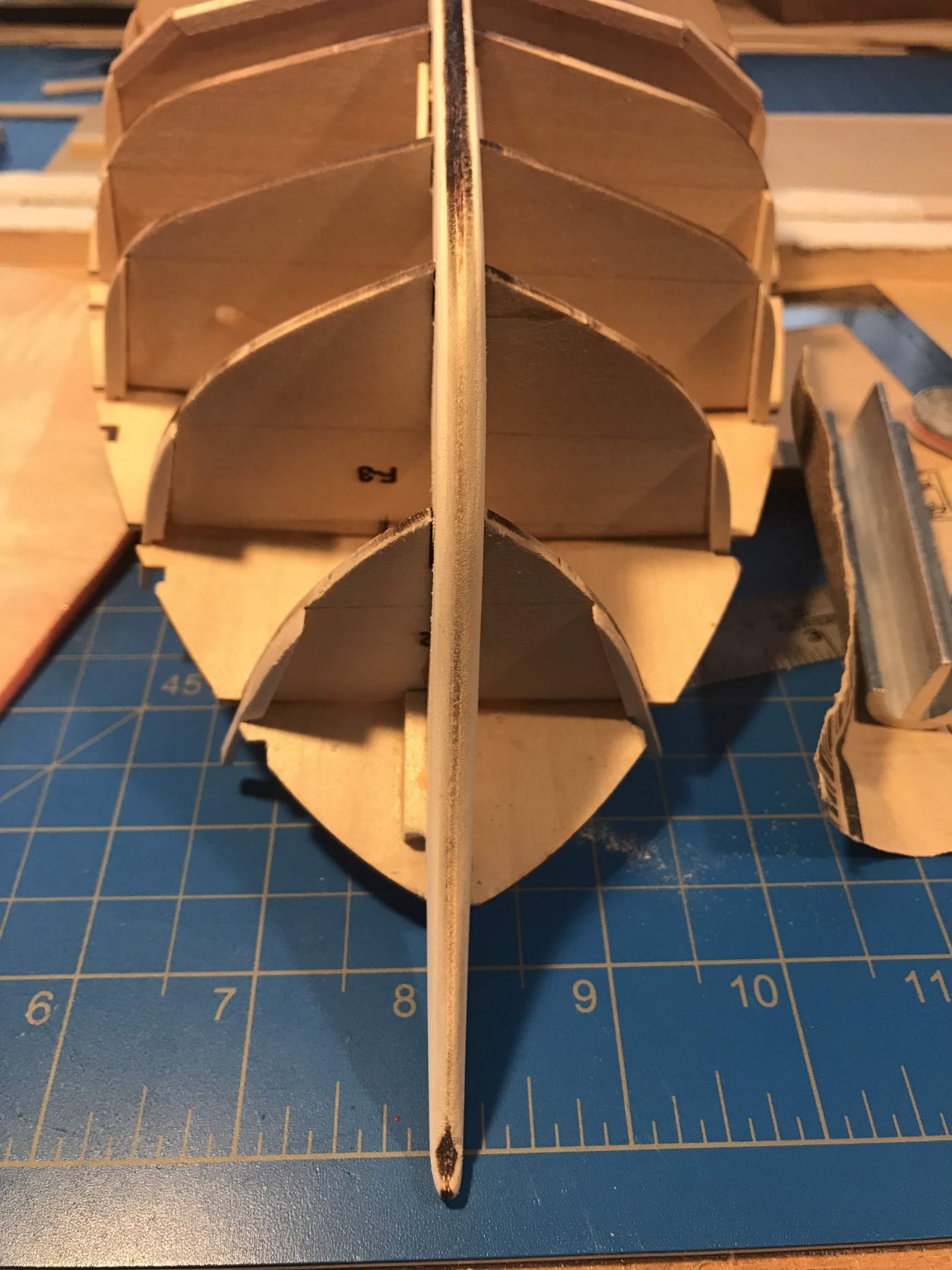
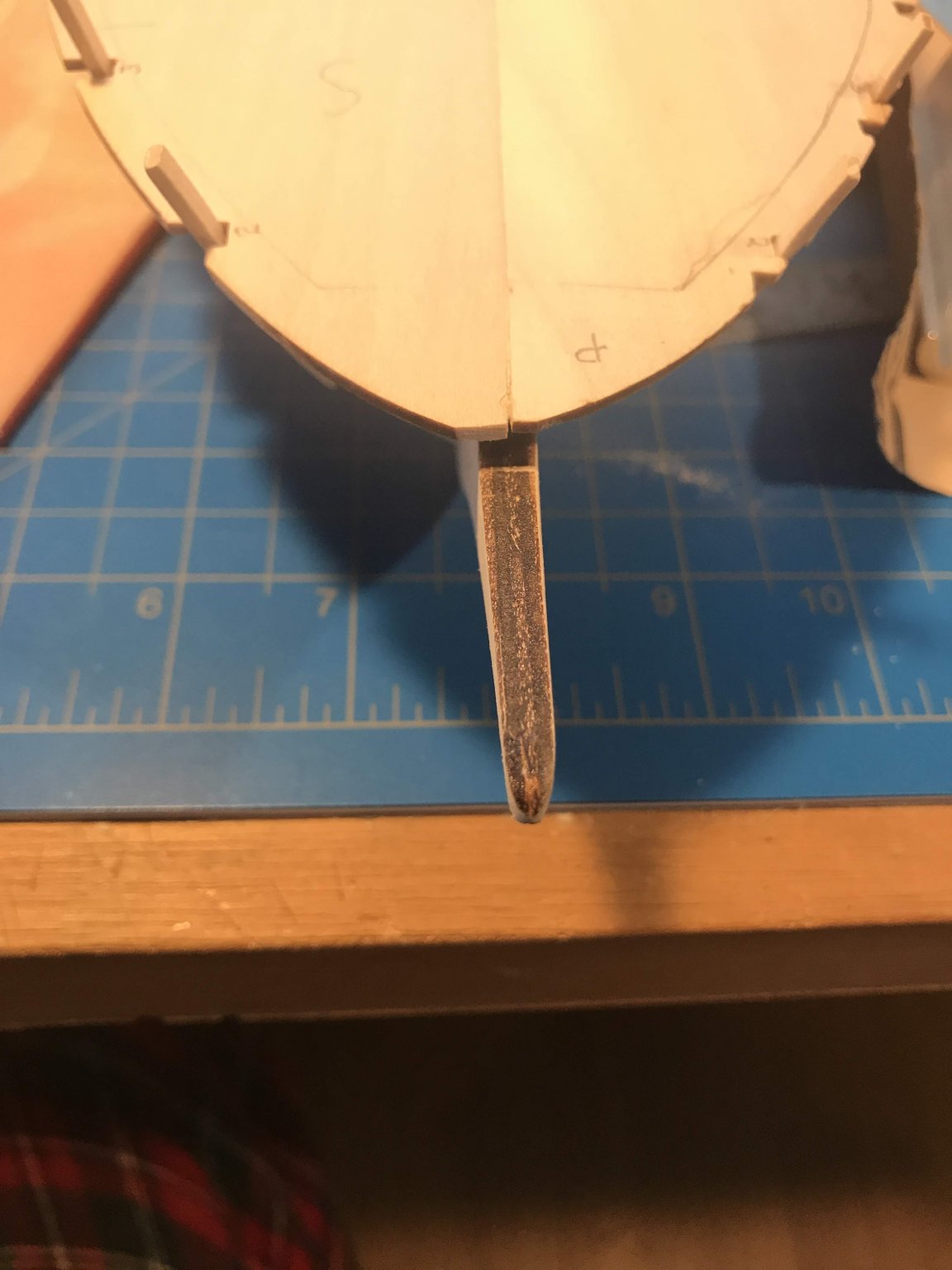
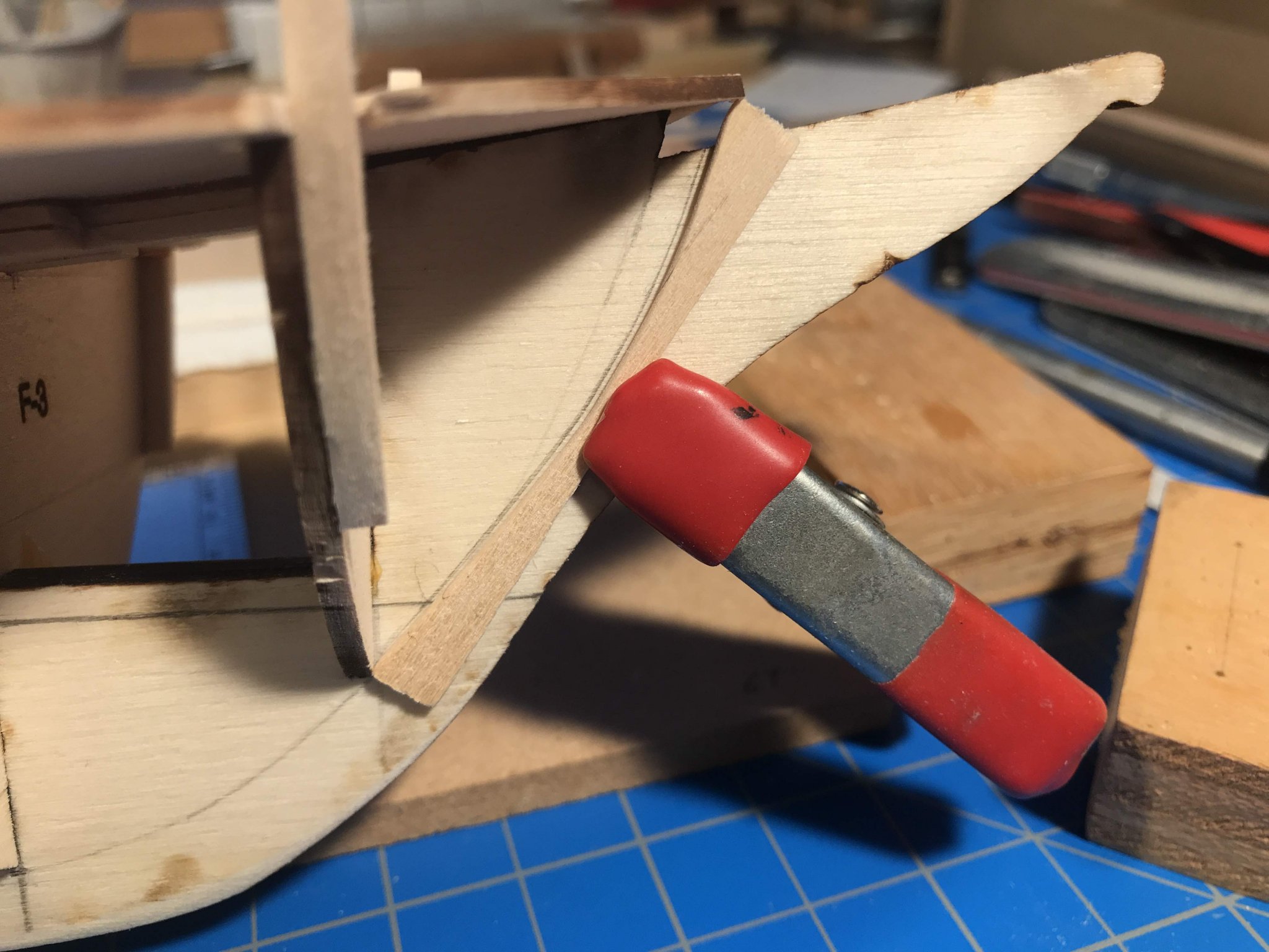
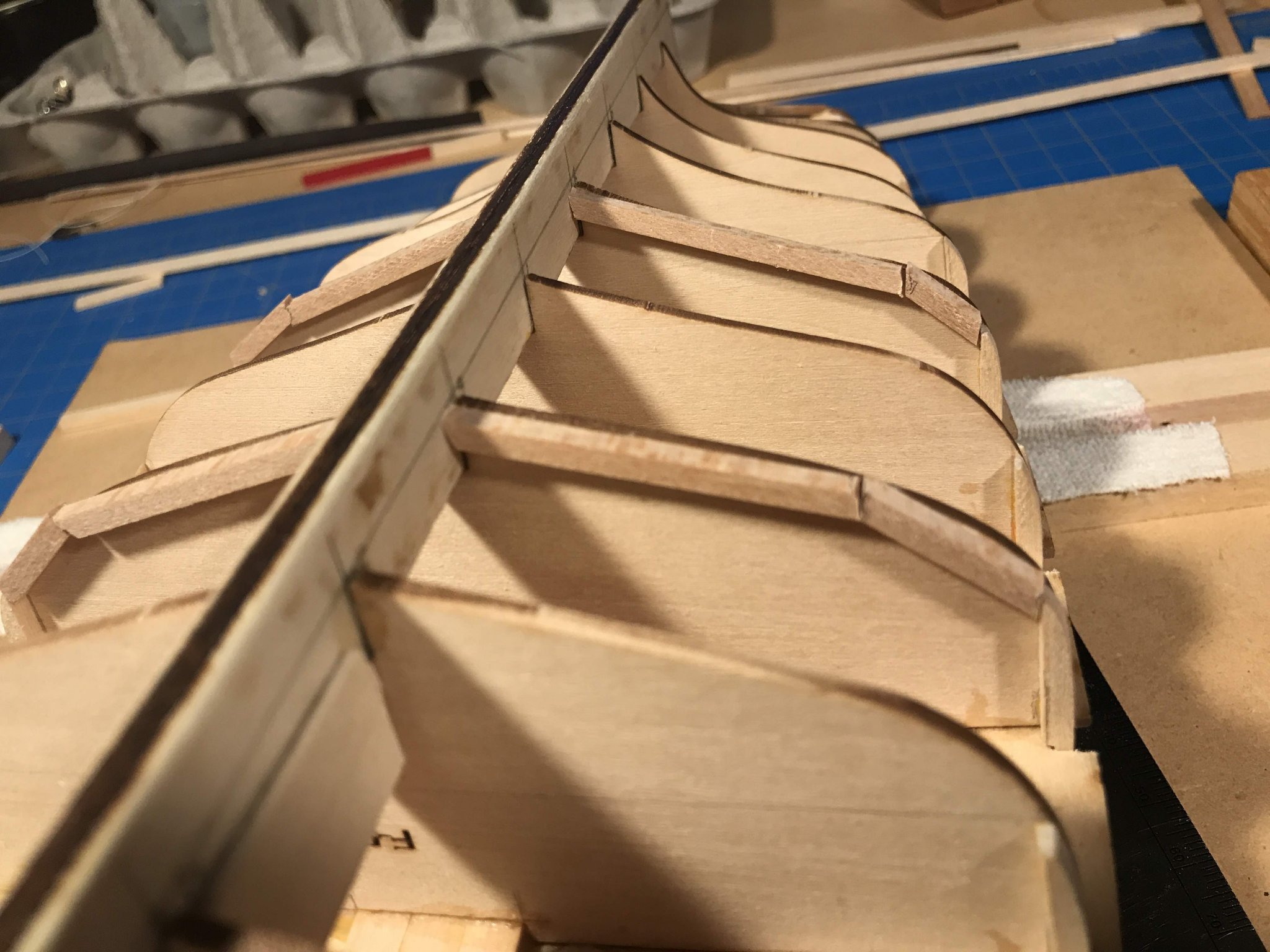
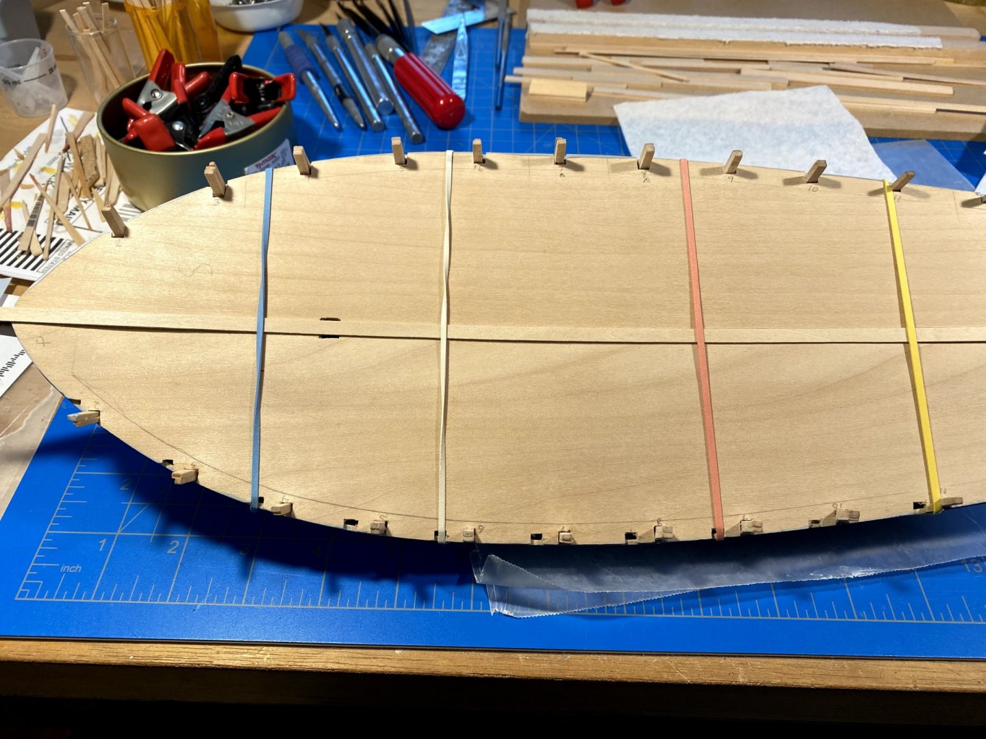
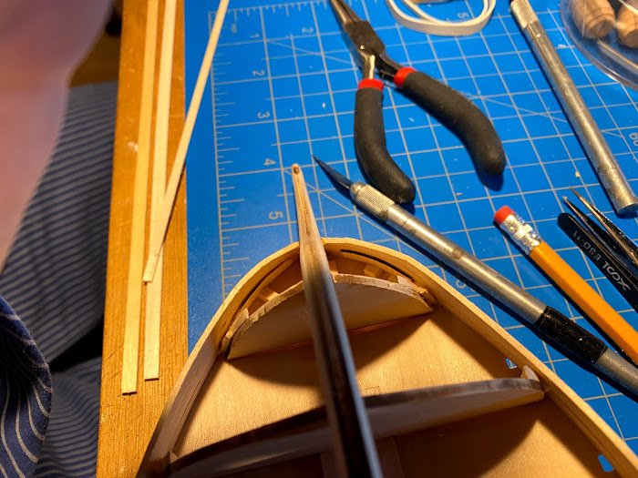
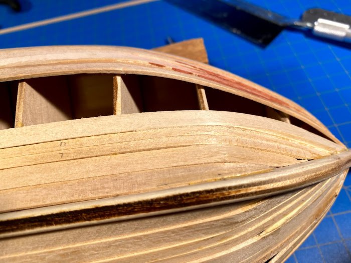
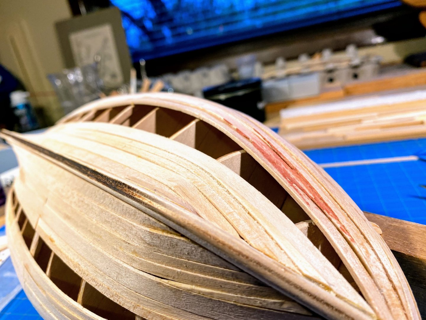
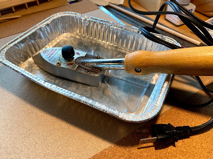
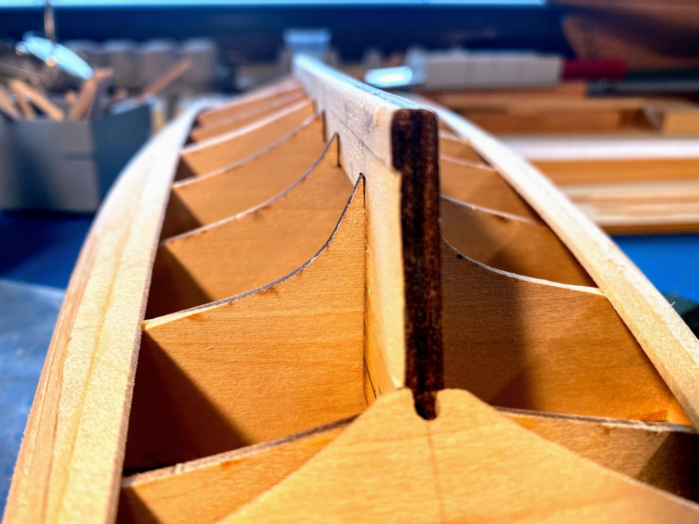
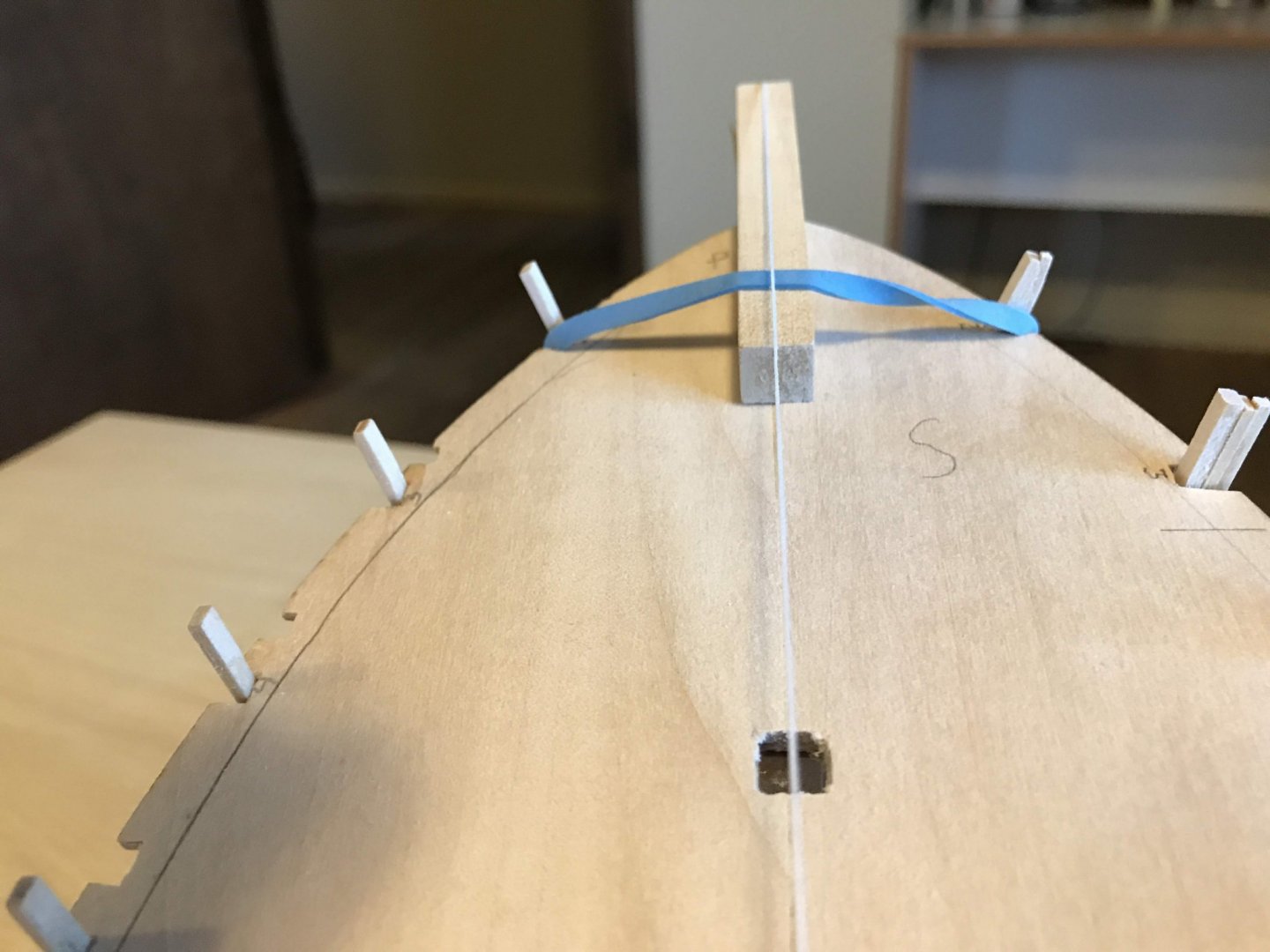
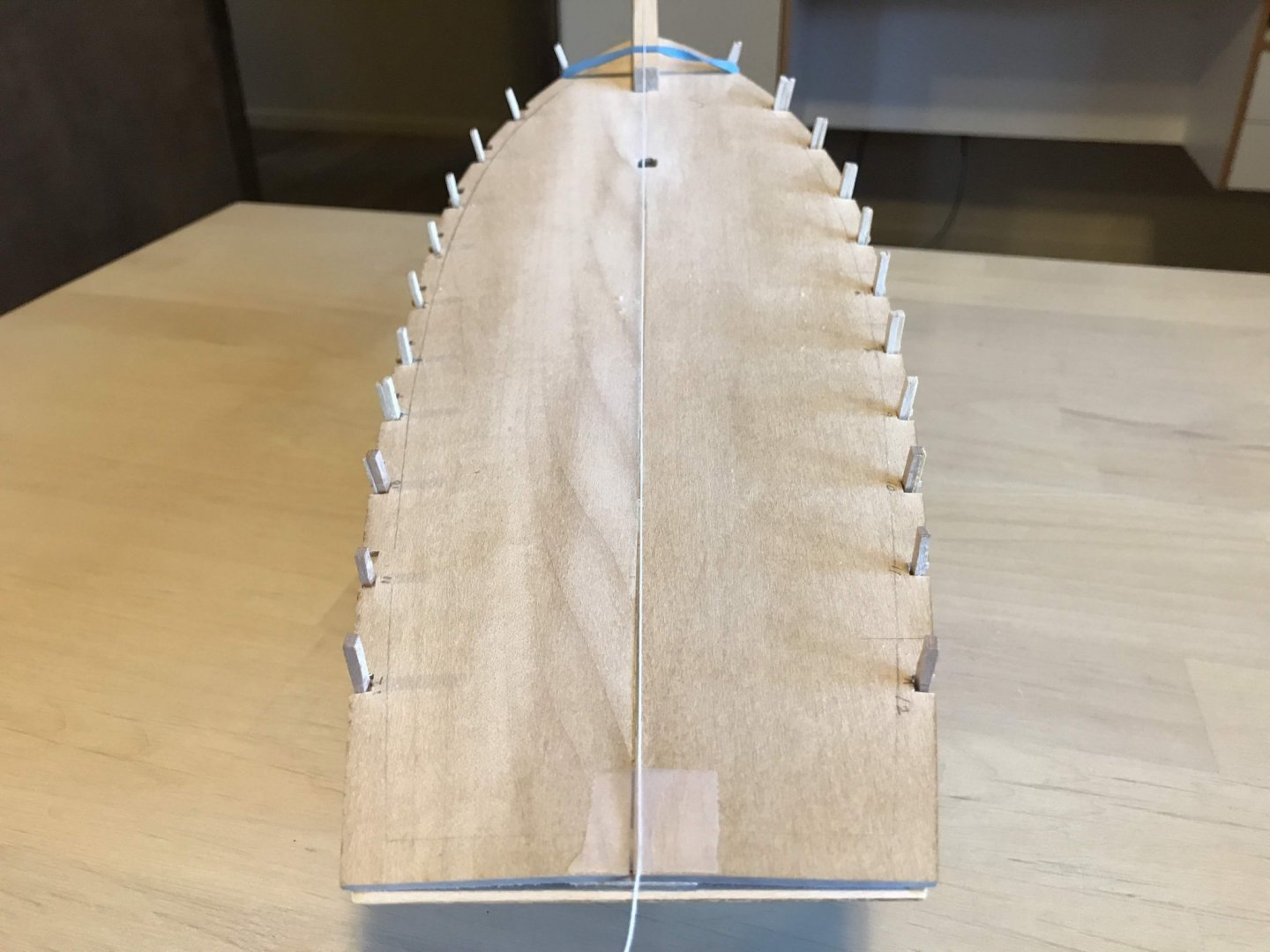
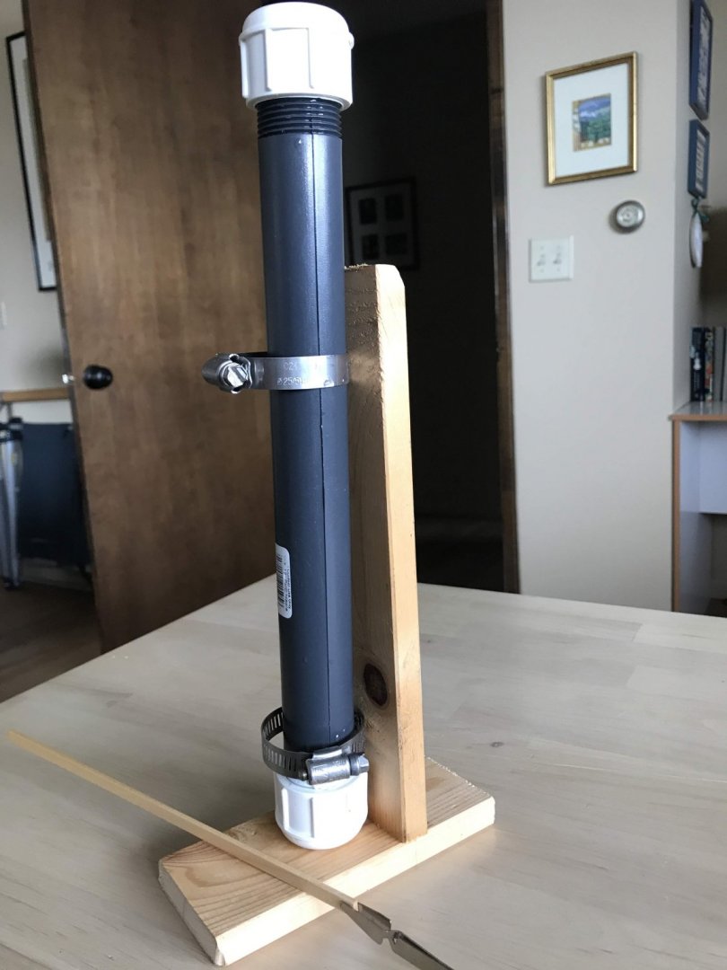
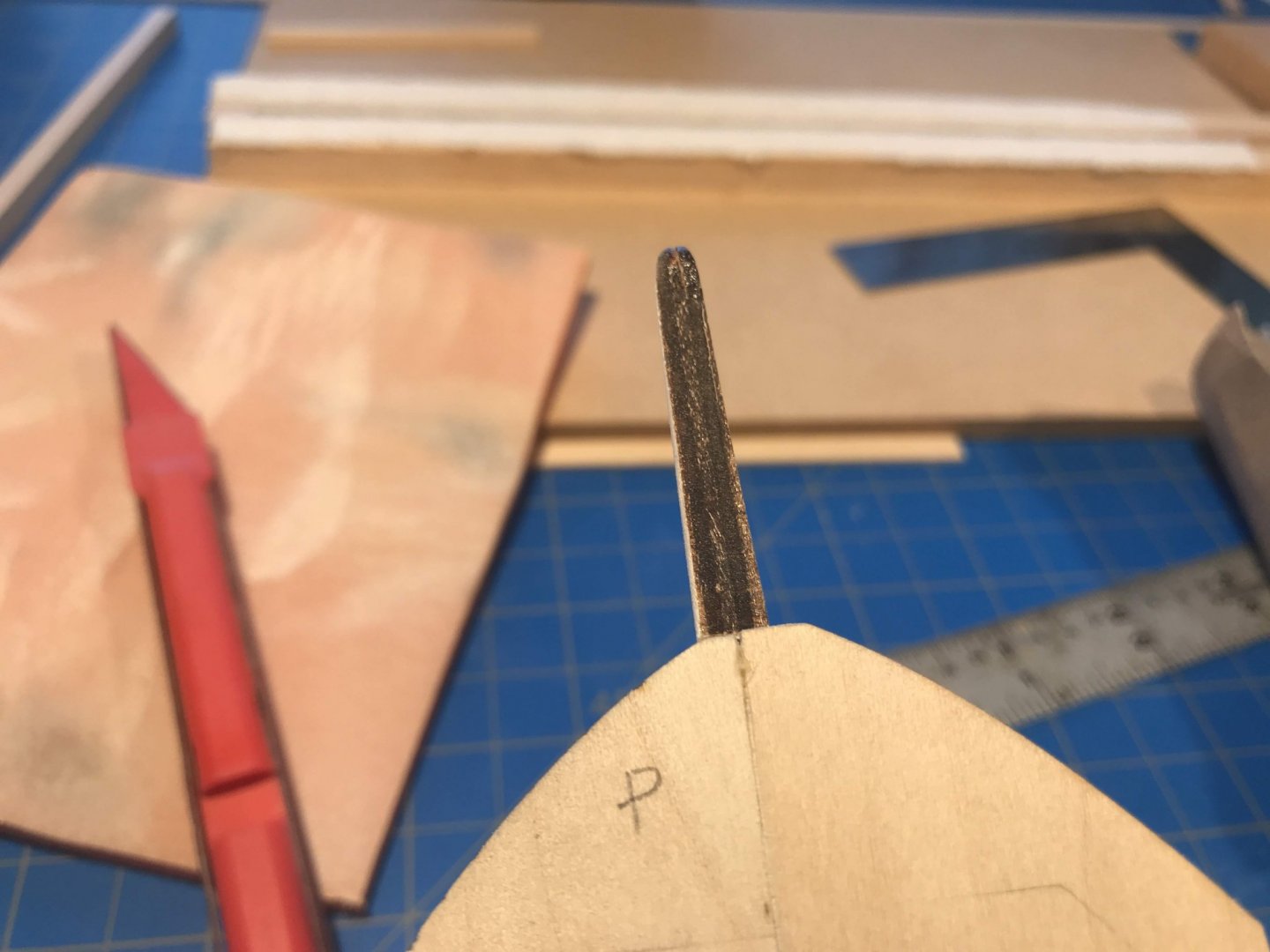
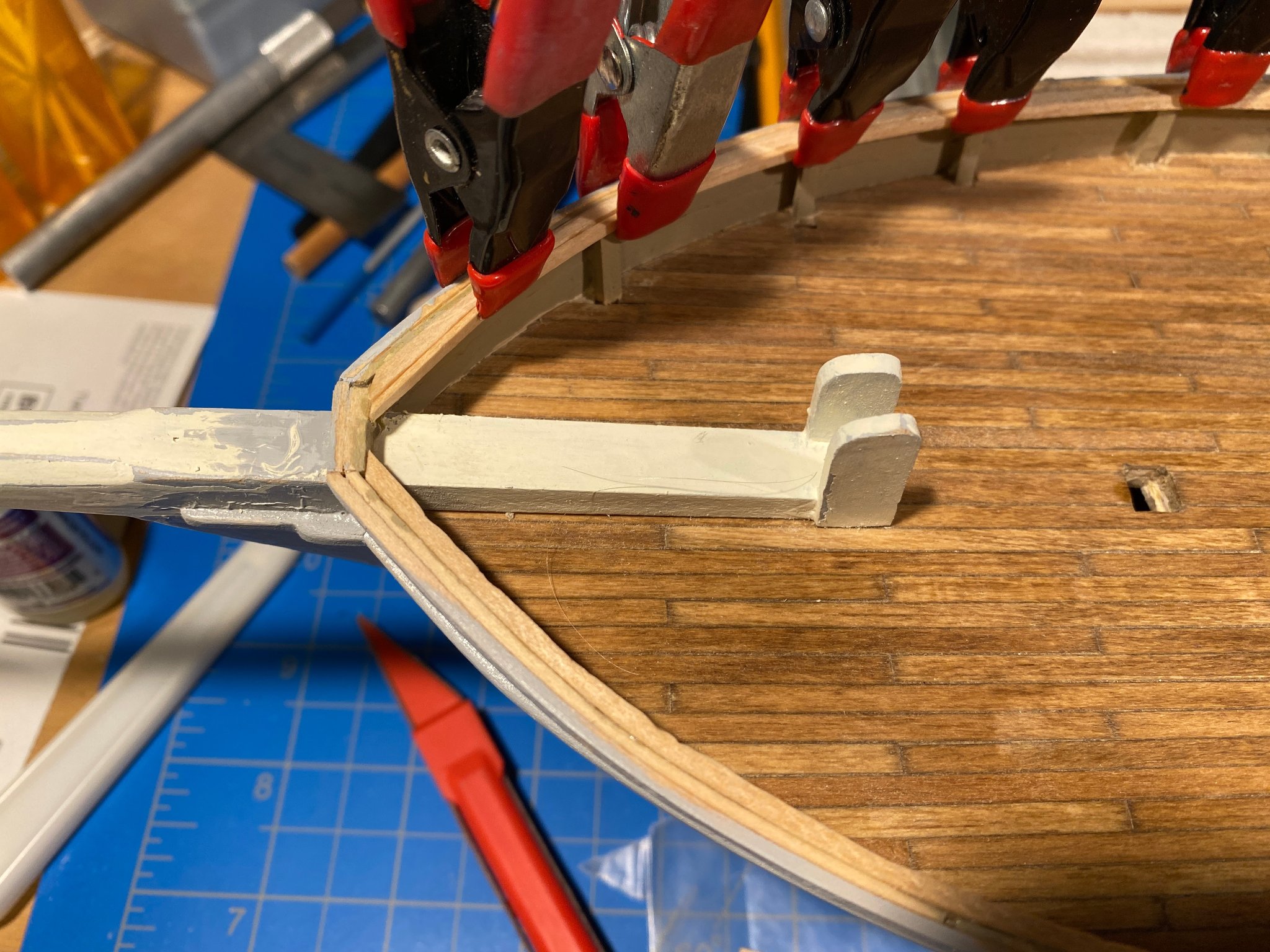
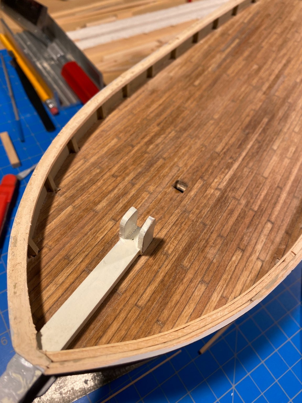
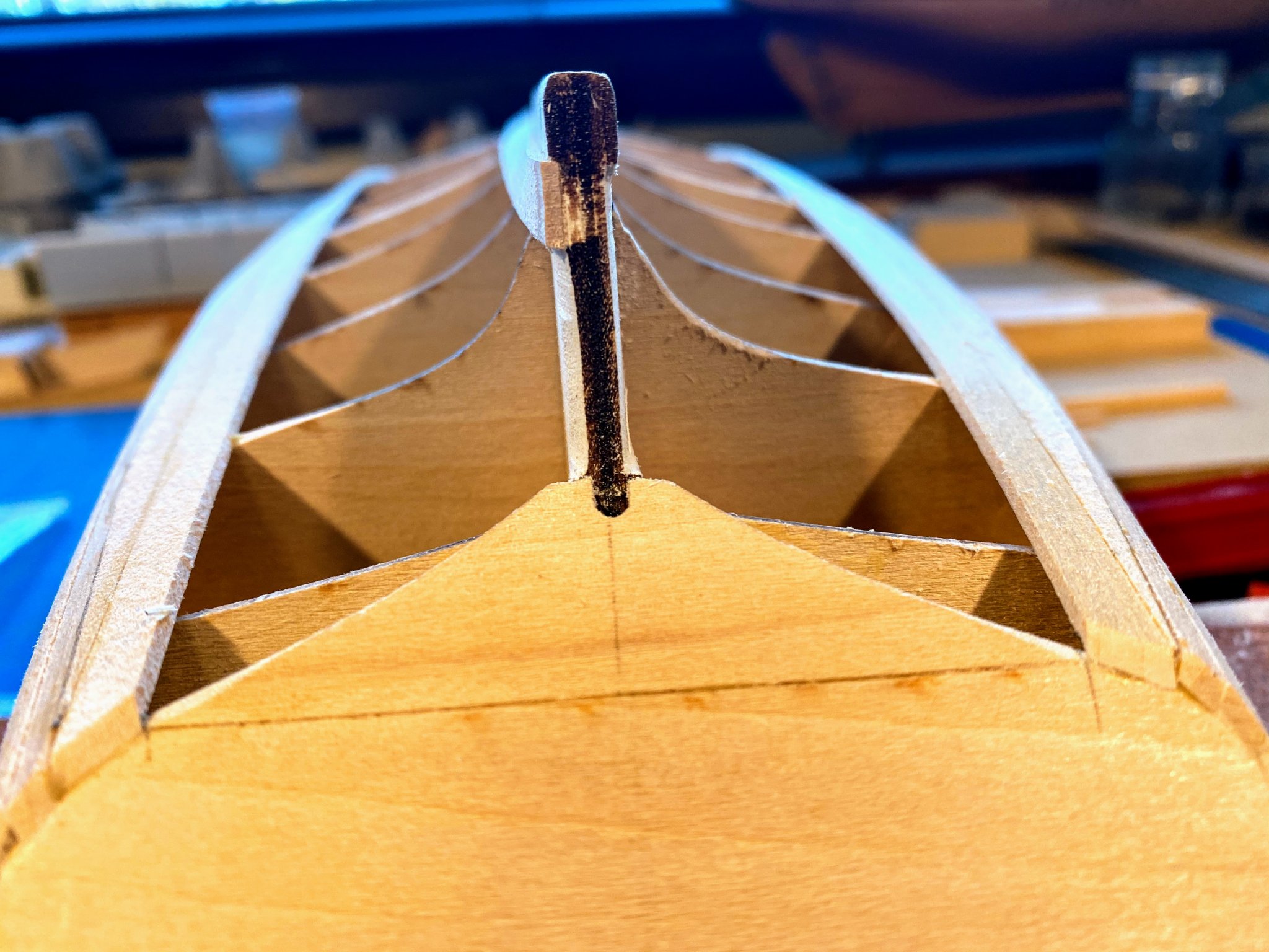
I have made a little progress on pre-planking matters. I decided that won’t try to use a single strip of wood to do an entire plank, except maybe at the keel where they aren’t quite so long. Instead I will alternate butting two strips together at bulkheads 6 and 8. I added some ⅛ by ⅛ pieces along the entirety of those bulkheads to add a little more surface area to which to glue the planks. The added wood hasn’t been trimmed closely yet, nor has it been beveled. One thing I did not do (and the instructions said nothing about doing) is to carve a rabbit in the keel piece where that planking meets that piece. Now I’m thinking I wish I had done so at the bow, to give the planks something to push against when they bend around from the forward-most bulkhead and meet the stem. So instead I carved a piece from a 1/4 x 1/16 strip that I can clamp to the stem. Hopefully that will be helpful when bending planks after they have been soaked/steamed. I don’t think I want to use it at the gluing stage for fear that some glue will seep out and glue that carved strip to the stem. I mentioned earlier that the subdeck extends a little bit forward of where it should; that can be seen in the picture below. The blunt stem offends my sense of how a sailing vessel should slice through the water. The ¼” piece in the model translates to something like 8” in the real boat. Somehow pushing an 8” plank through the water broadside just doesn’t cut it. So I tapered the stem to something like ⅛” at the bowsprit (actually I think I got bored and quit a little before I got it quite that thin). I had previously rounded the sharp corners of the keel, and as part of the tapering I transitioned from rounded corners to a rounded leading edge, beginning about where the keel starts to rise to the stem. As I look at the pictures I don’t think they really do it justice, but you get the idea. Finally, most recently I built a soaking device, using a 1” by 12” pvc pipe, and borrowing a few ideas I have seen posted on these forums. The small clamp (X-acto brand) attached to the strip of wood is heavy enough to keep a 10” strip from floating in the tube. Now (or at least a few days from now) onto beveling the stanchions and bulkheads. One thing I am wondering about is whether the inner surfaces of the stanchions in the bow (which will be visible above deck) should be parallel to the bulwark planking rather than parallel to the center line as they are now. I’m thinking that they should be. I suspect I will be adding shims as much as I am carving/sanding wood away.


- 82 replies
-
- 3
-
-
- spray
- BlueJacket Shipcrafters
- (and 1 more)


.jpg.f4bb2aeb2cd86c92d399f751f2ff8580.jpg)


.jpg.5aa7d8efa4de5f70aa7acb4ebfcbe336.jpg)