HOLIDAY DONATION DRIVE - SUPPORT MSW - DO YOUR PART TO KEEP THIS GREAT FORUM GOING! (89 donations so far out of 49,000 members - C'mon guys!)
×


Tomculb
-
Posts
345 -
Joined
-
Last visited
Content Type
Profiles
Forums
Gallery
Events
Everything posted by Tomculb
-
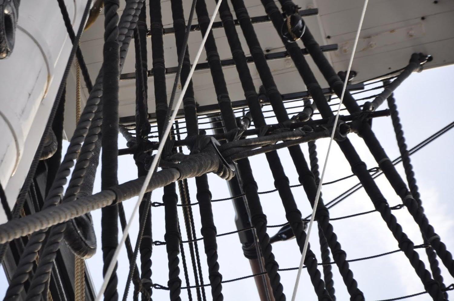
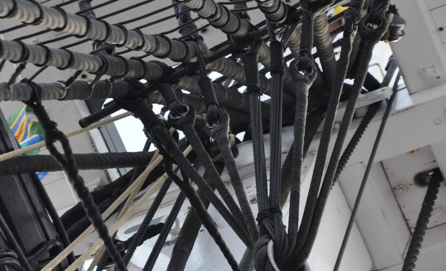
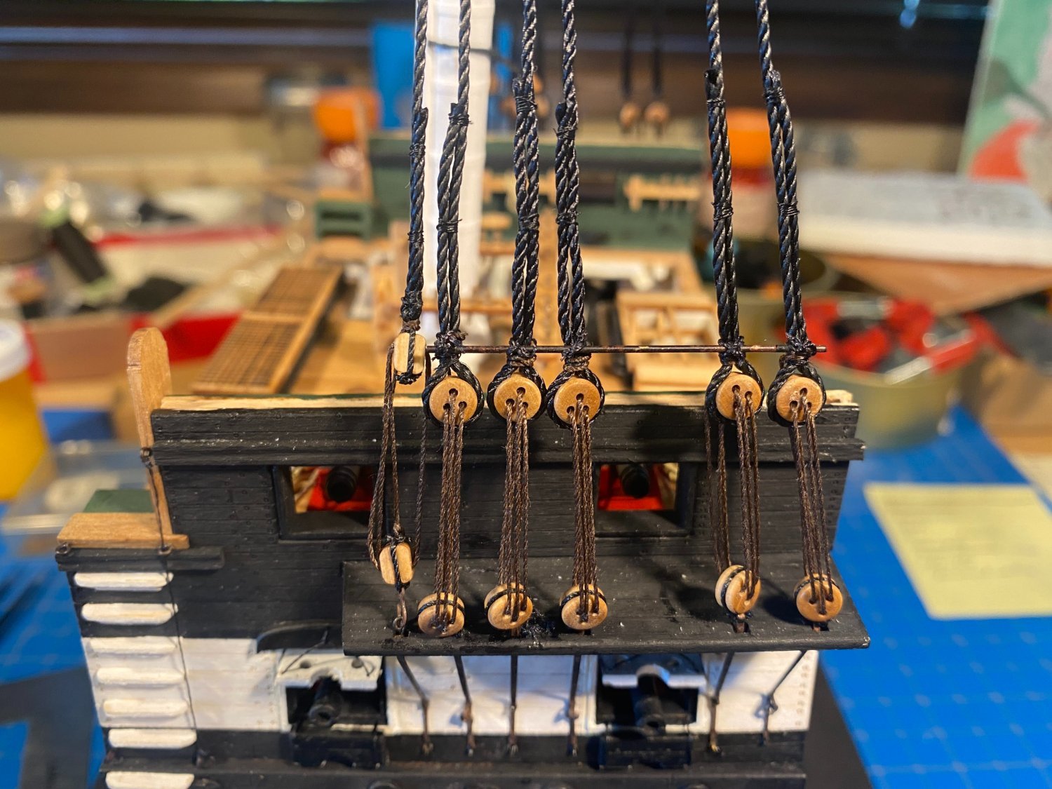
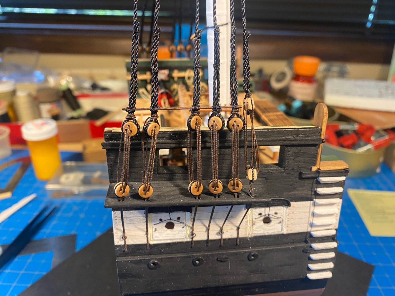
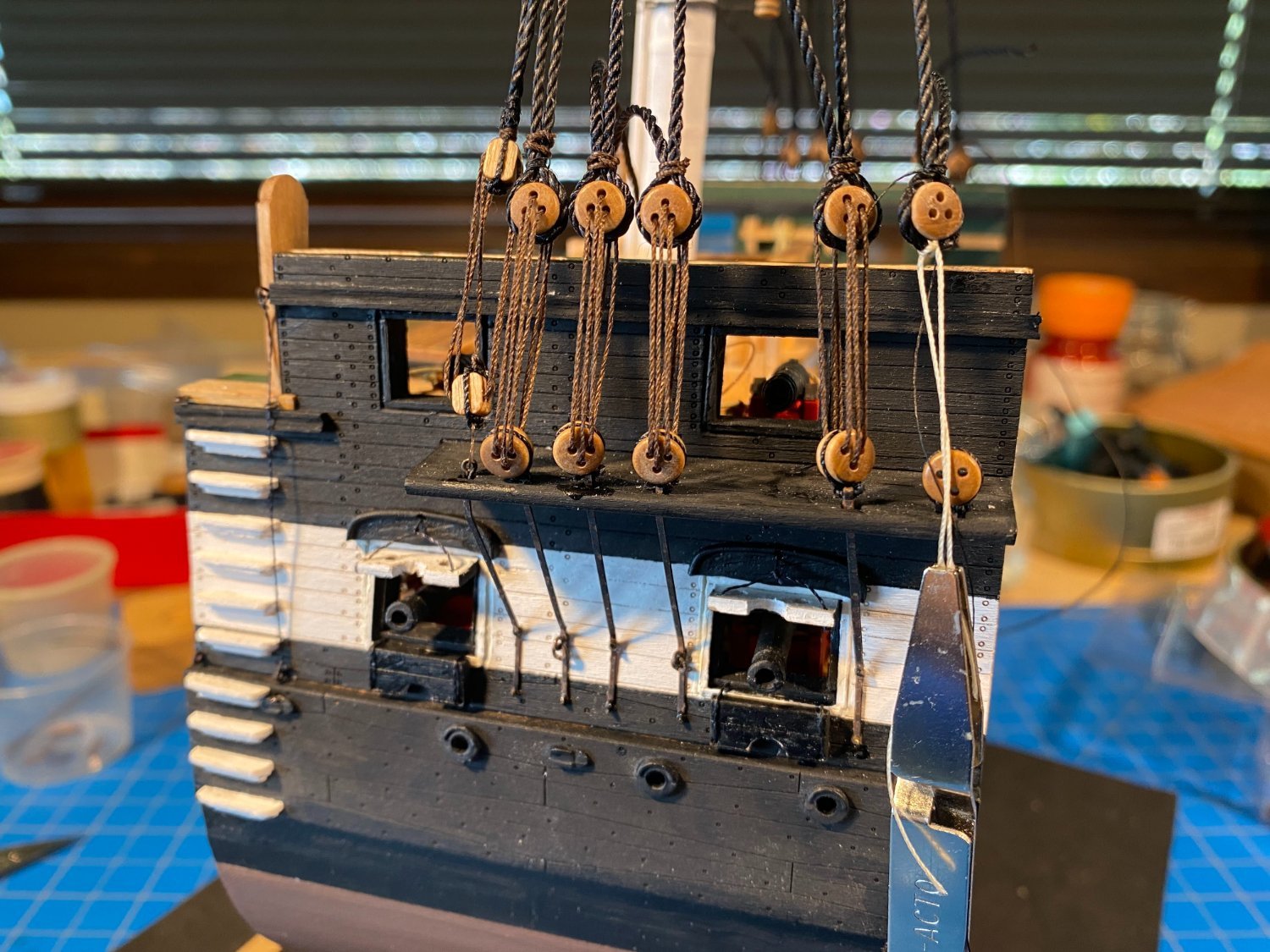
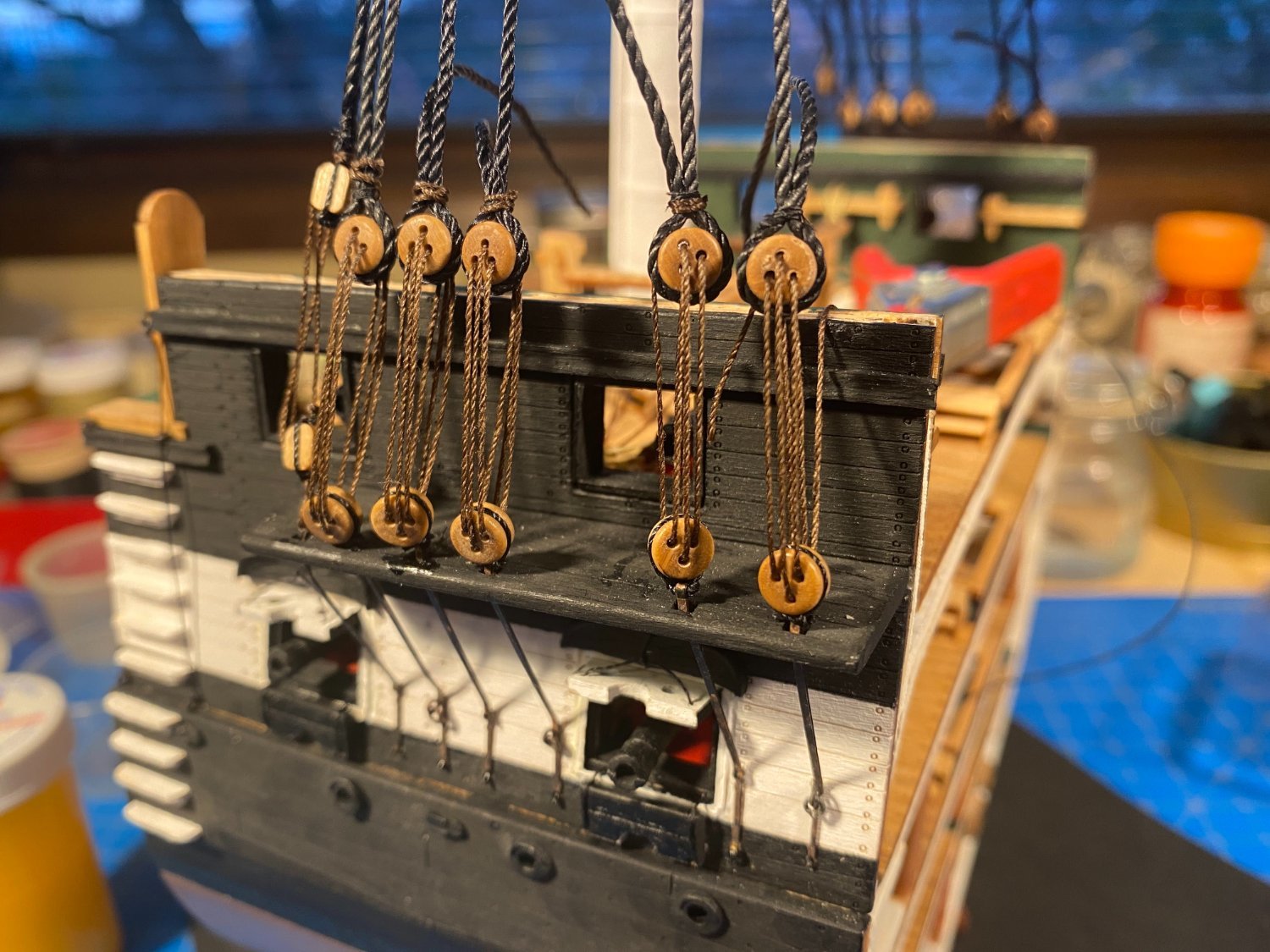
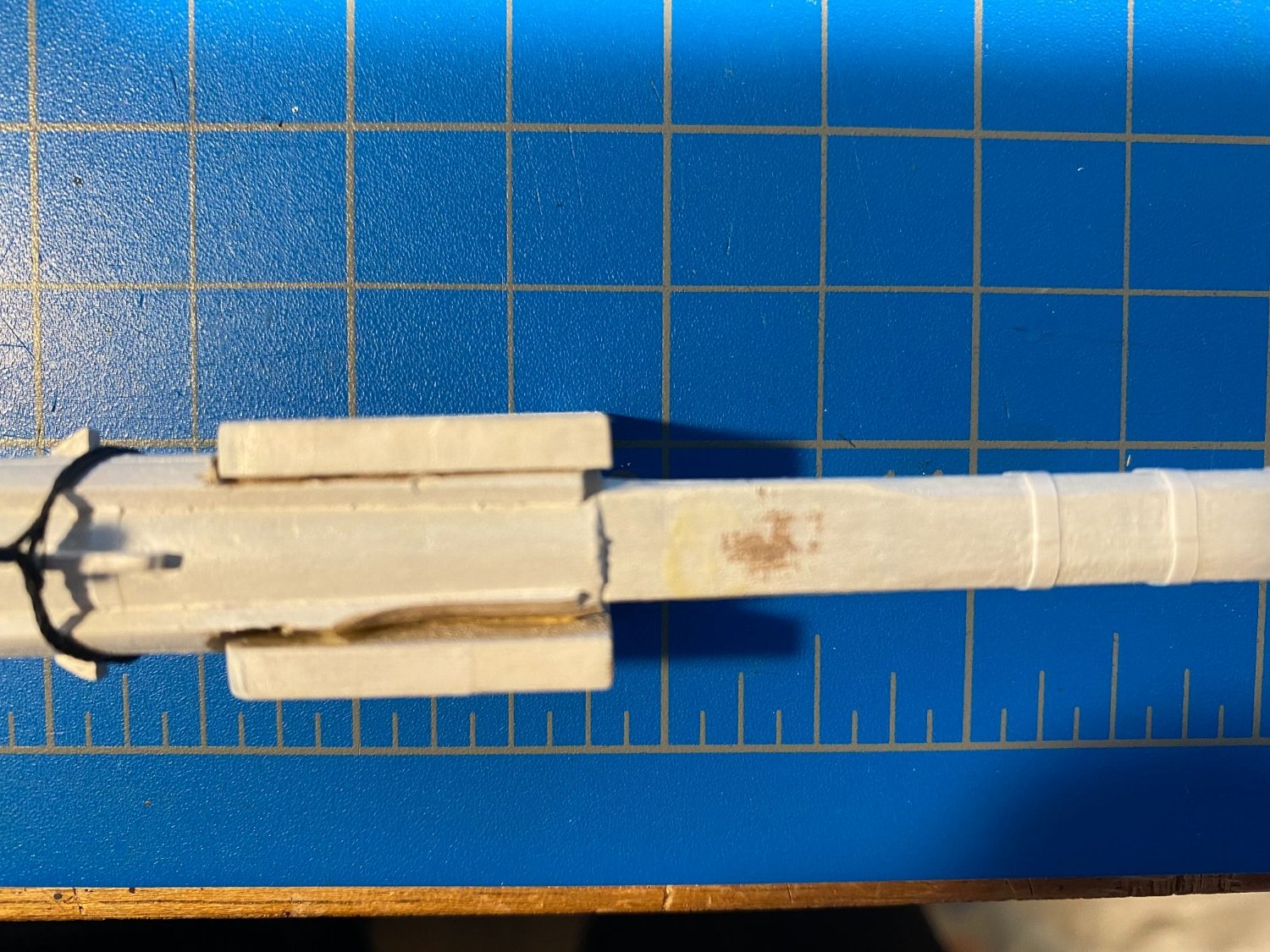
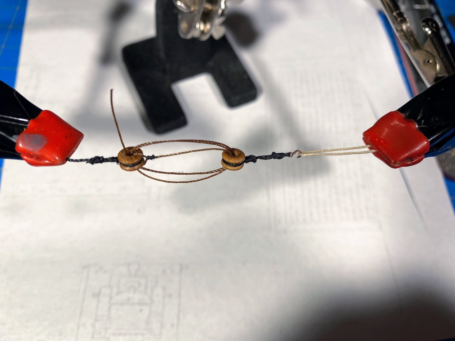
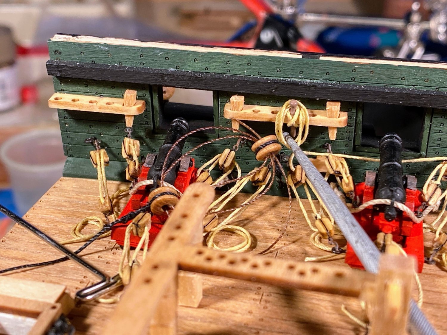
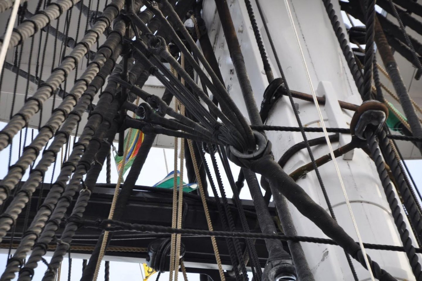
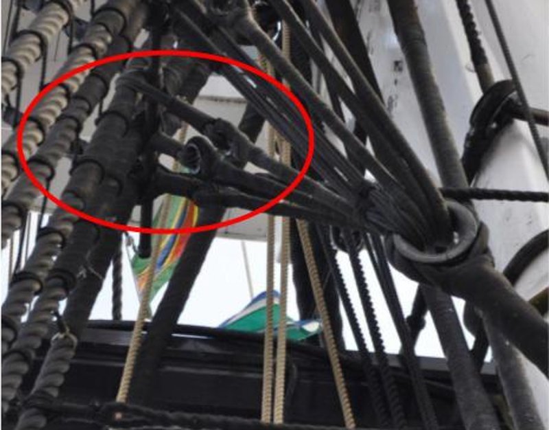
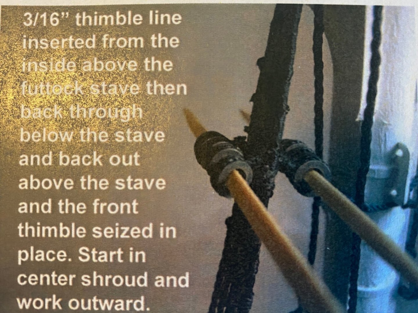
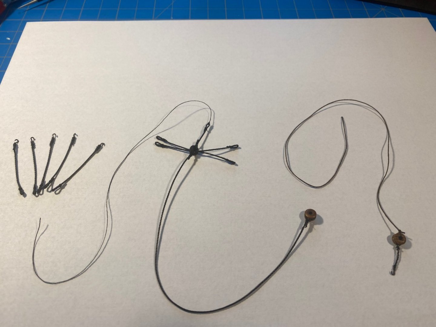
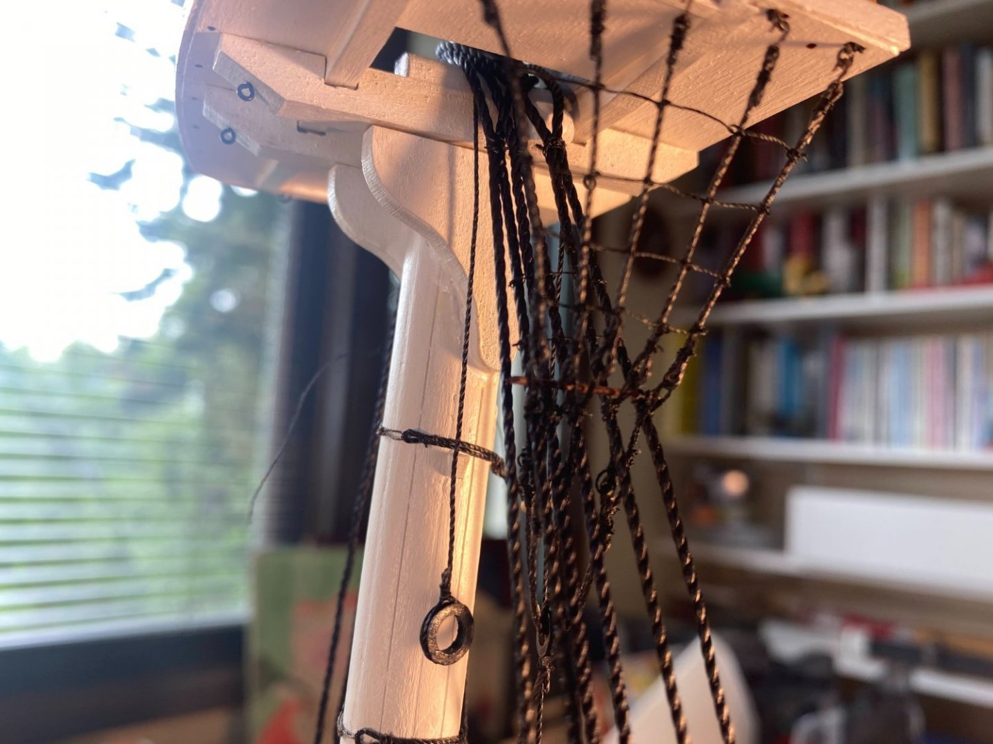
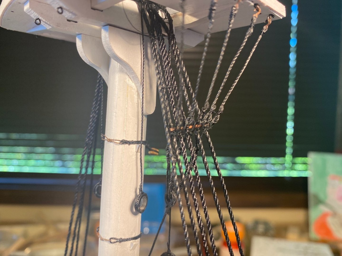
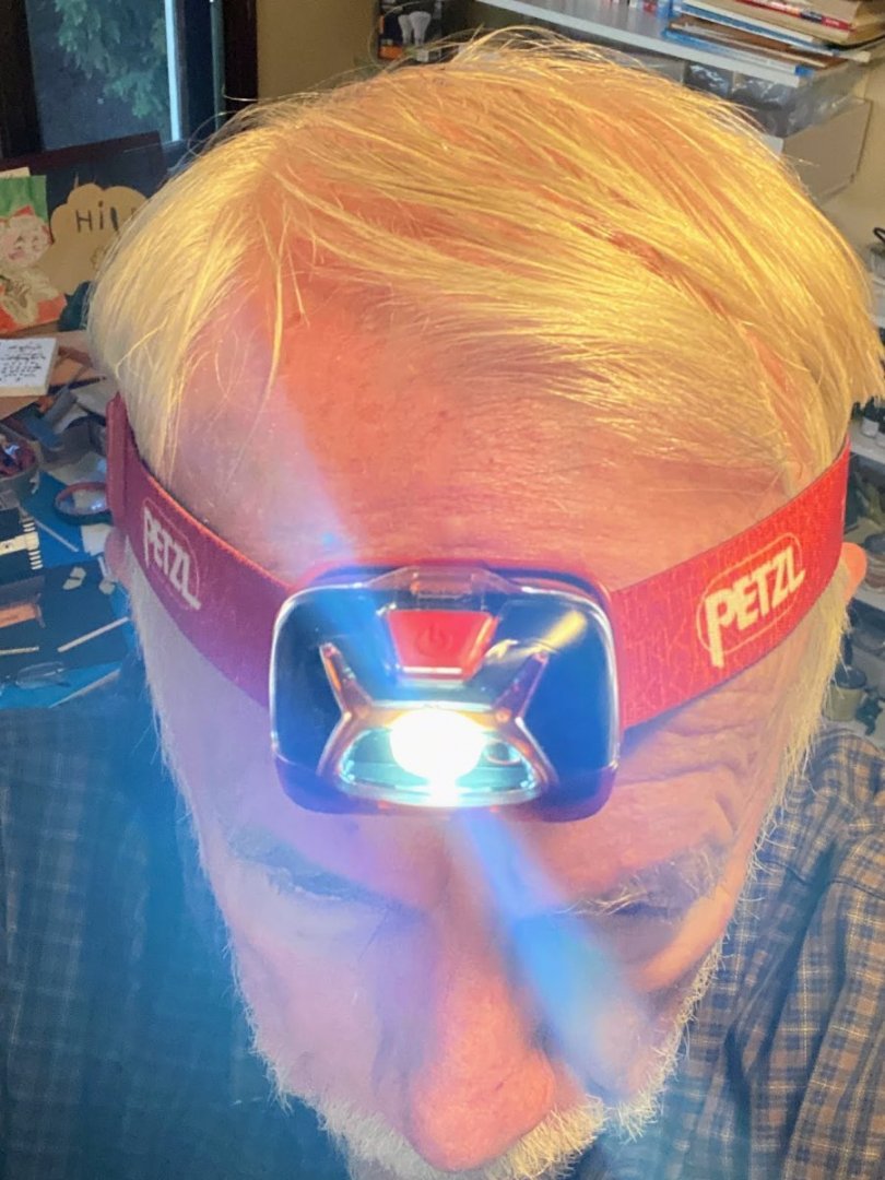
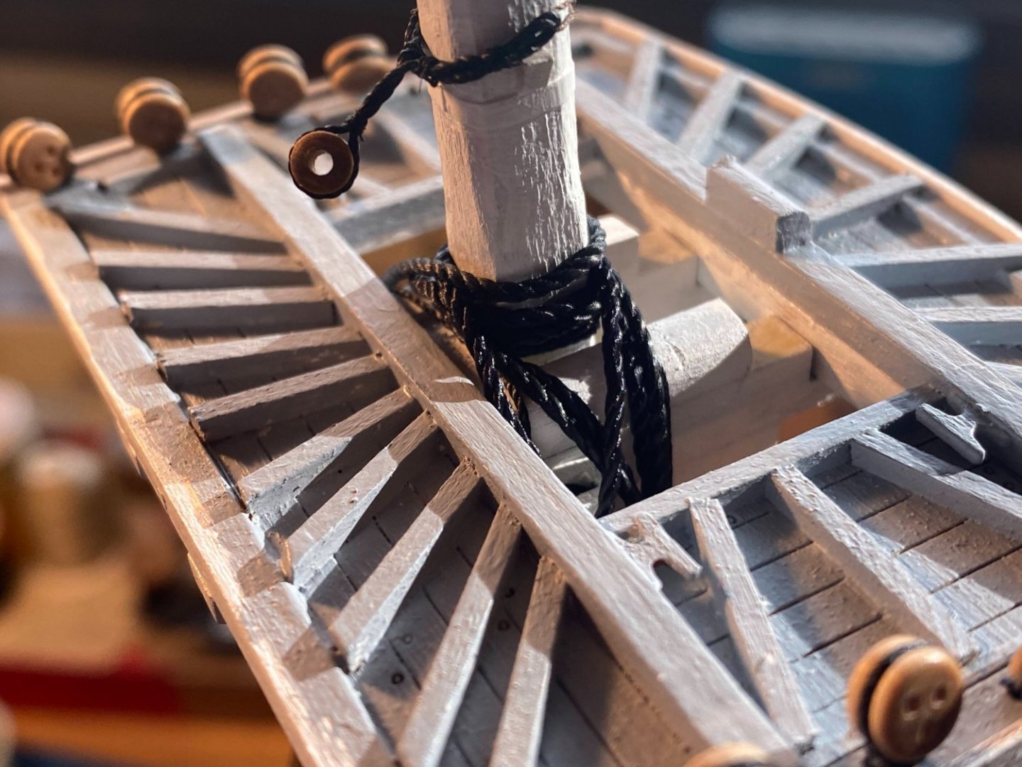
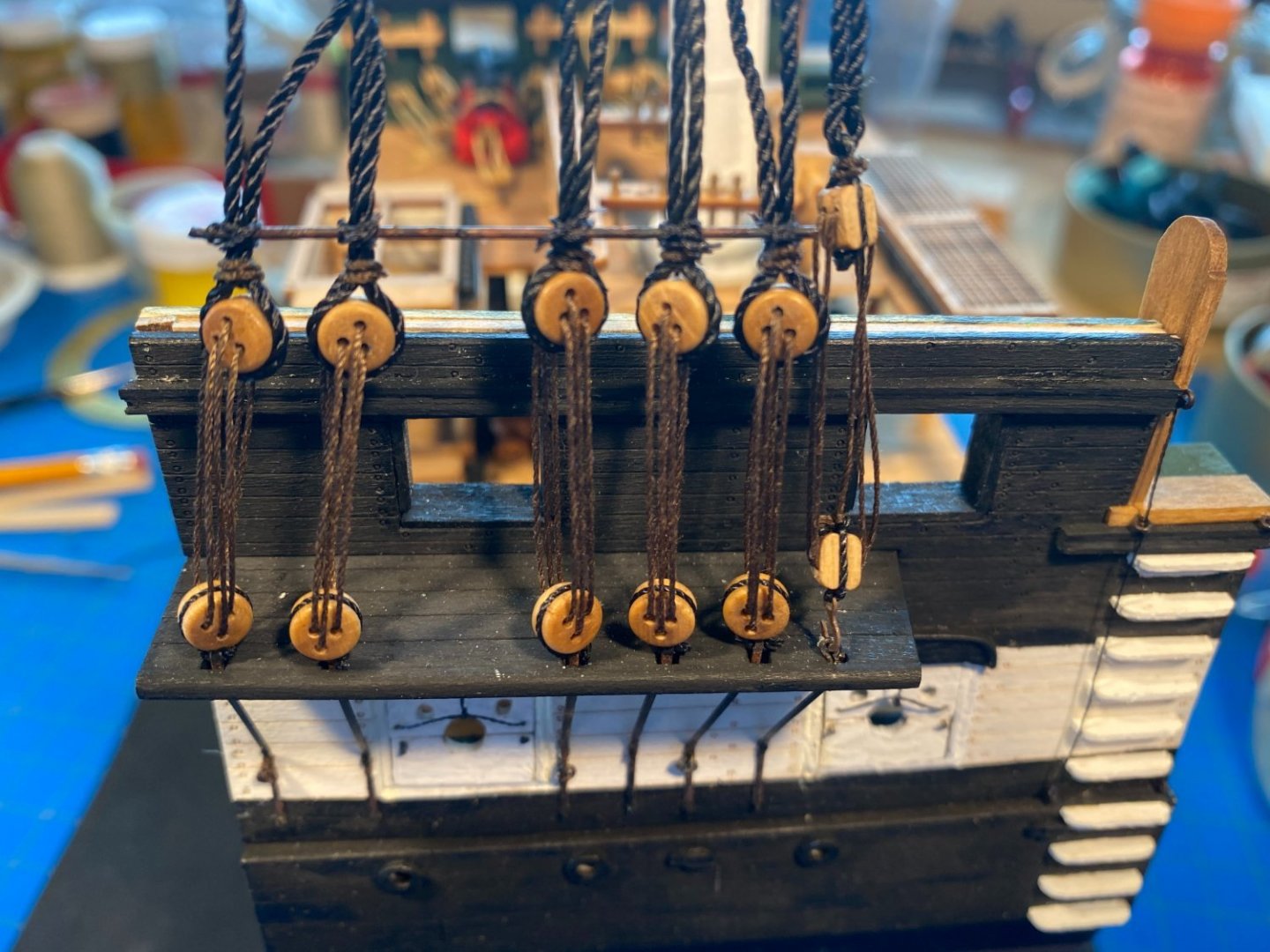
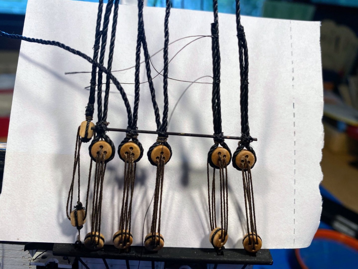
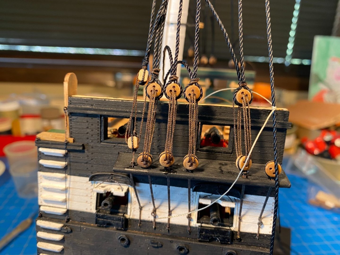
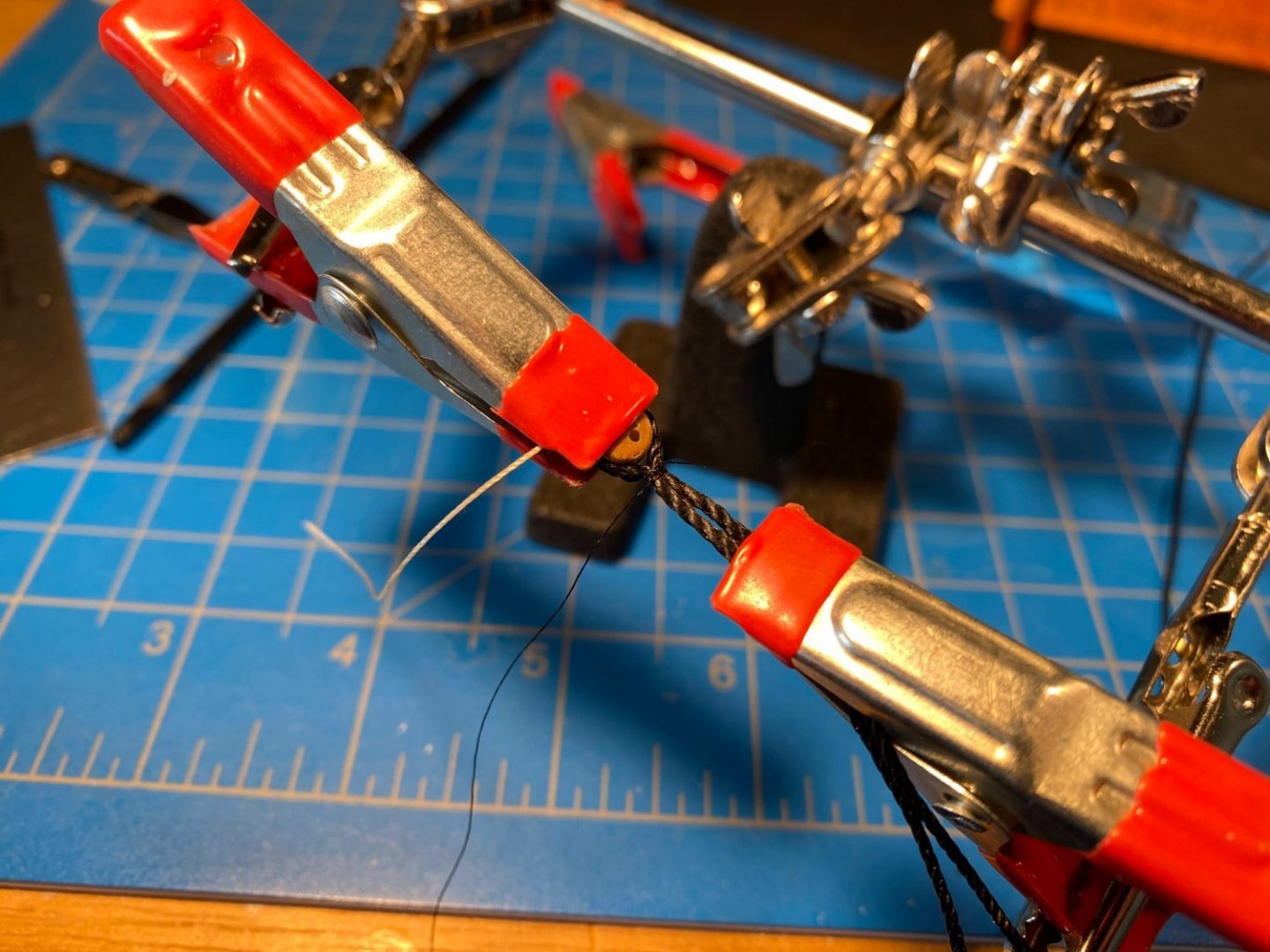
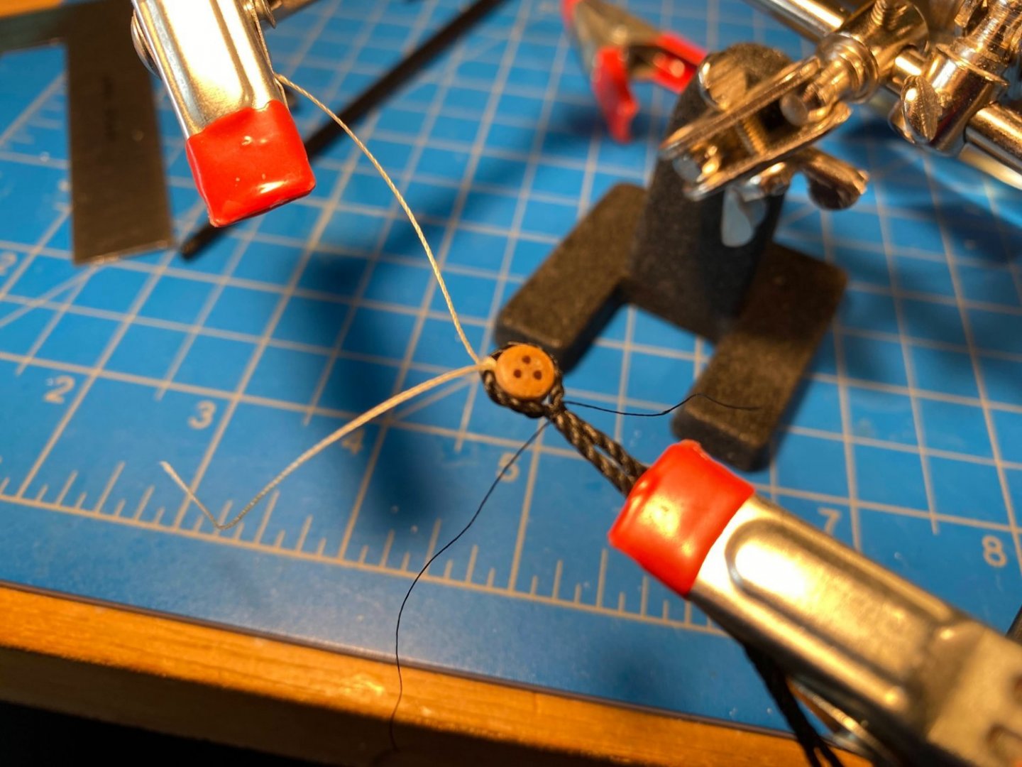
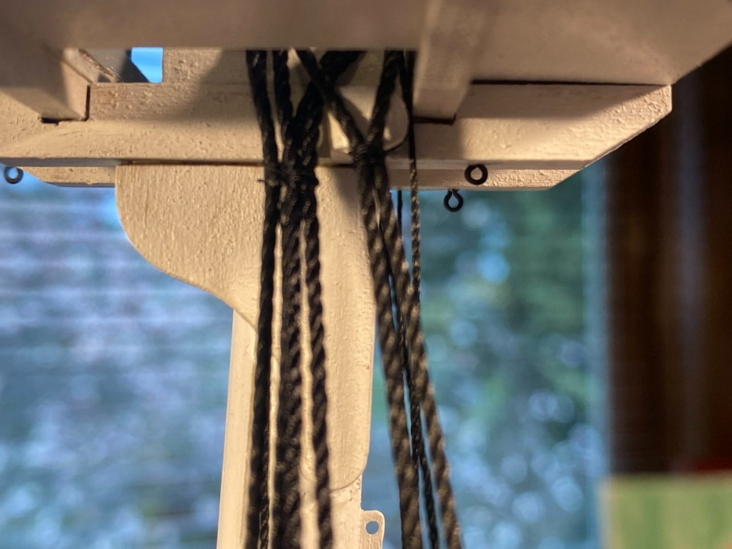
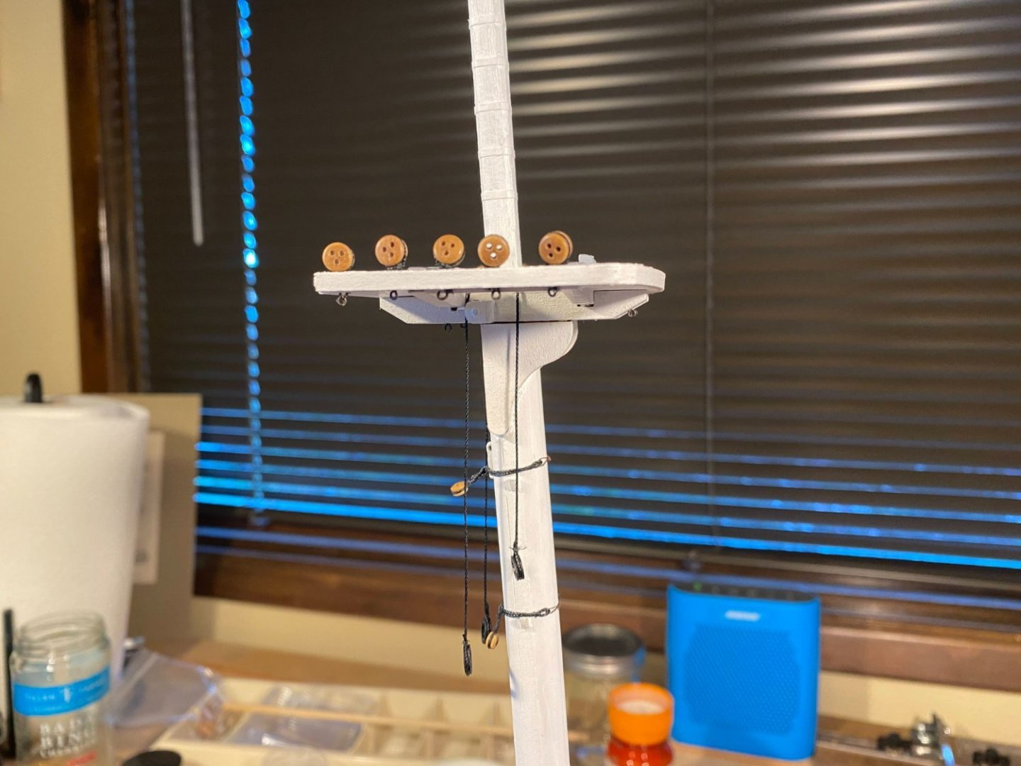
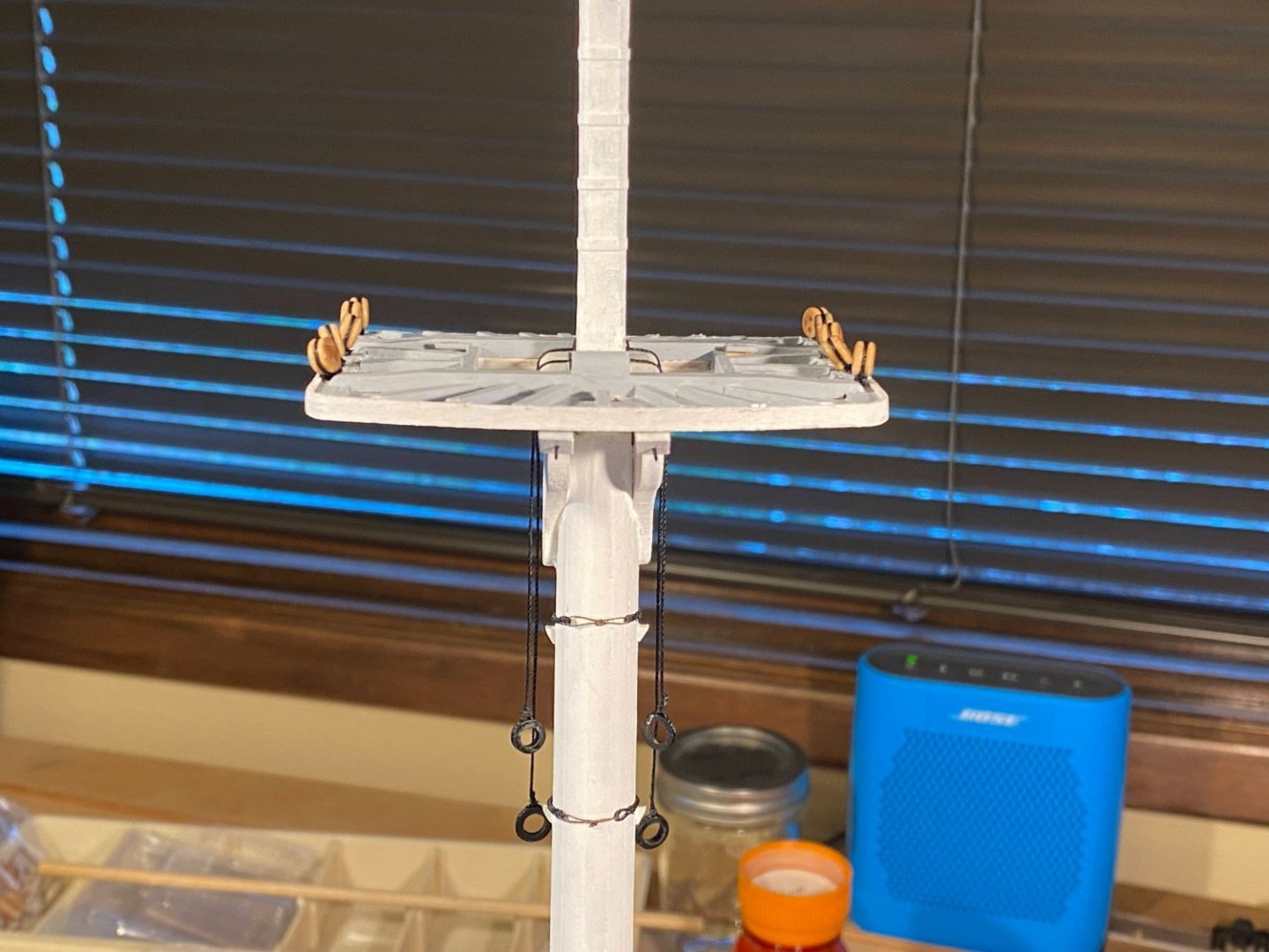
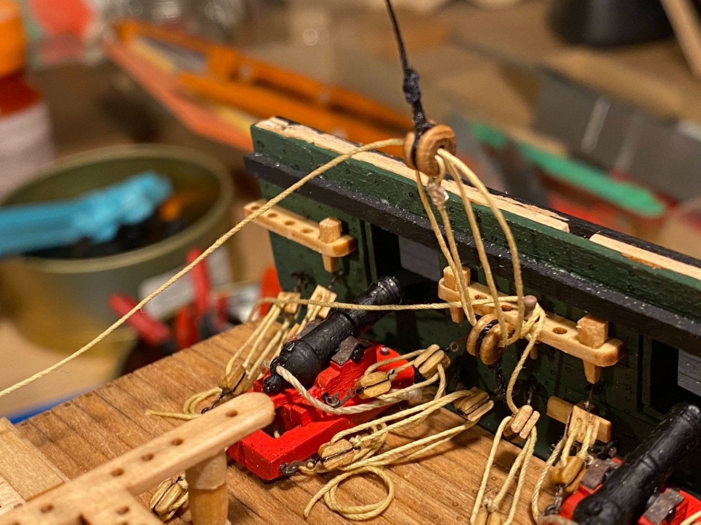
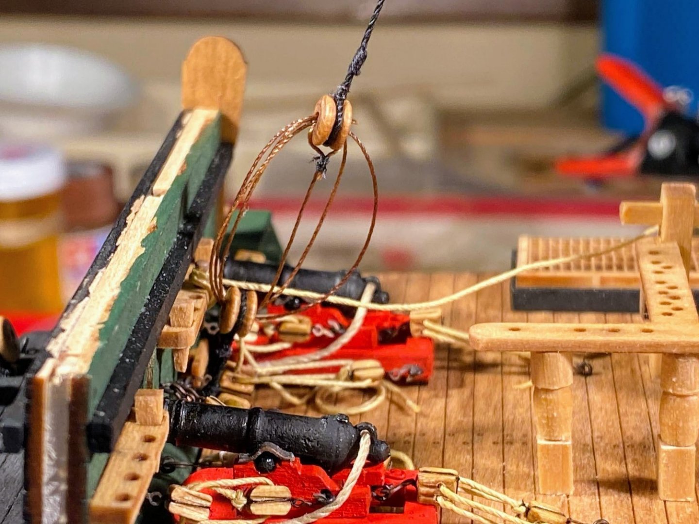
 On each side, the futtock shrouds run from the eyebolts on the bottom of the fighting top (below the topsail shroud deadeyes), down to a ring at the top of the bentinck shroud. The bentinck shroud runs down from there across to an eyebolt previously installed (hopefully) in the waterway on the opposite side. The whole assembly is designed to secure the upper mast standing rigging (topsail, topgallant and royal shrouds) to the hull and not just to the fighting top. Back in February I expressed puzzlement as to the rigging of the futtock shrouds, especially where they intercept the lower main shrouds. Photos supplied by usedtosail and JSGerson were a huge help in getting me educated. Thank you. Each futtock shroud has three parts, an upper one hooked to an eyebolt on the fighting top, a lower one attached to the ring at the top of the bentinck shroud, and a middle one connecting the other two in the immediate vicinity of the main shroud. The middle part appears to be some sort of lanyard (adjustable standing rigging), and that is the way it is depicted in the instructions to MS’s full Connie kit. In the picture below it appears to have some sort of anti-chafing cover (probably a late 18th century equivalent to Kevlar). 😀 I don’t care much for this kit’s approach. It has large, circular thimbles seized just below the hooks at the upper end of the upper part, and on either side of the main shroud (the latter being the middle part). Because they are circular and too large, these thimbles do not look like anything on the real ship. The real ship does appear to have thimbles in these places, but they are tear shaped, not round, and they are small enough to be almost impossible to duplicate at this scale. Also, put together per the kit, instead of running a straight line with the bentinck shroud, the futtock shrouds would take an awkward, and unrealistic, jog at the main shroud, as seen in this picture in the instructions. There are a lot of parts to these shrouds. The picture below shows how I put them all together for the starboard side futtock shrouds (yet to be installed), after having a very difficult time rigging everything on the port side. From left to right are: 5 futtock shroud upper parts, with a hook at the upper end and a small tear shaped loop at the other end The bentinck shroud with (from top to bottom): the lanyard which will be the middle part of the center futtock shroud the lower part of the center futtock shroud a large ring, through which run two pairs of futtock shroud lower parts, with loops at each end, to which I will tie the middle part lanyards, and a bullseye seized at the lowest end The lowest part of the bentinck shroud, at one end of which is the hook which engages the eyebolt in the waterway, and at the other end a bullseye to which is tied the dark brown lanyard will be lash the two bullseyes together. Rigging this was a matter of lashing the lower part of each futtock shroud to the corresponding upper part, and that proved to be difficult and at times very frustrating. Rigging the first one (the center one) took me over 2 hours spread over 3 different attempts. The biggest part of the problem was being able to see clearly what I was working on, due in part to the fact that I wear monovision contacts; that is, one eye adjusted for distance and the other for closeup. They work amazingly well for just about everything (including biking and skiing). But for this closeup work and with multiple layers of rigging in front of me, I had difficulty getting my eyes to focus on the layer I needed to see. A big help was finding a very bright headlight stashed among some camping gear. With the lamp, perseverance, focus and some salty seaman’s language, I got the other four rigged in less time than it took to rig the first one. After finishing that task, I lashed the futtock stave to the main mast shrouds, then rigged a couple of ratlines on those shrouds so that the less courageous members of my crew (that would be me) can climb through the lubber hole in the fighting top. That rigging was also quite difficult since I had the futtock shrouds between me and what I was working on. One of the ratlines is missing in the second picture below -- the glue didn't hold well enough and it came untied from the shroud. ☹️ Finally I rigged some ratlines to the futtock shrouds, a task which was much easier than what had preceded it. So now moving on to doing it all over again on the other side. As can be seen from the picture of all the parts above, I rigged everything I could before attaching anything to the model, something I had not done the first time around. I will also lash the futtock stave and a couple of ratlines to the main shrouds before installing the futtock shrouds. All of this should make things a little easier. I admire those of you who have built models of the entire ship . . . I only have to do this twice, and you have done it six times!
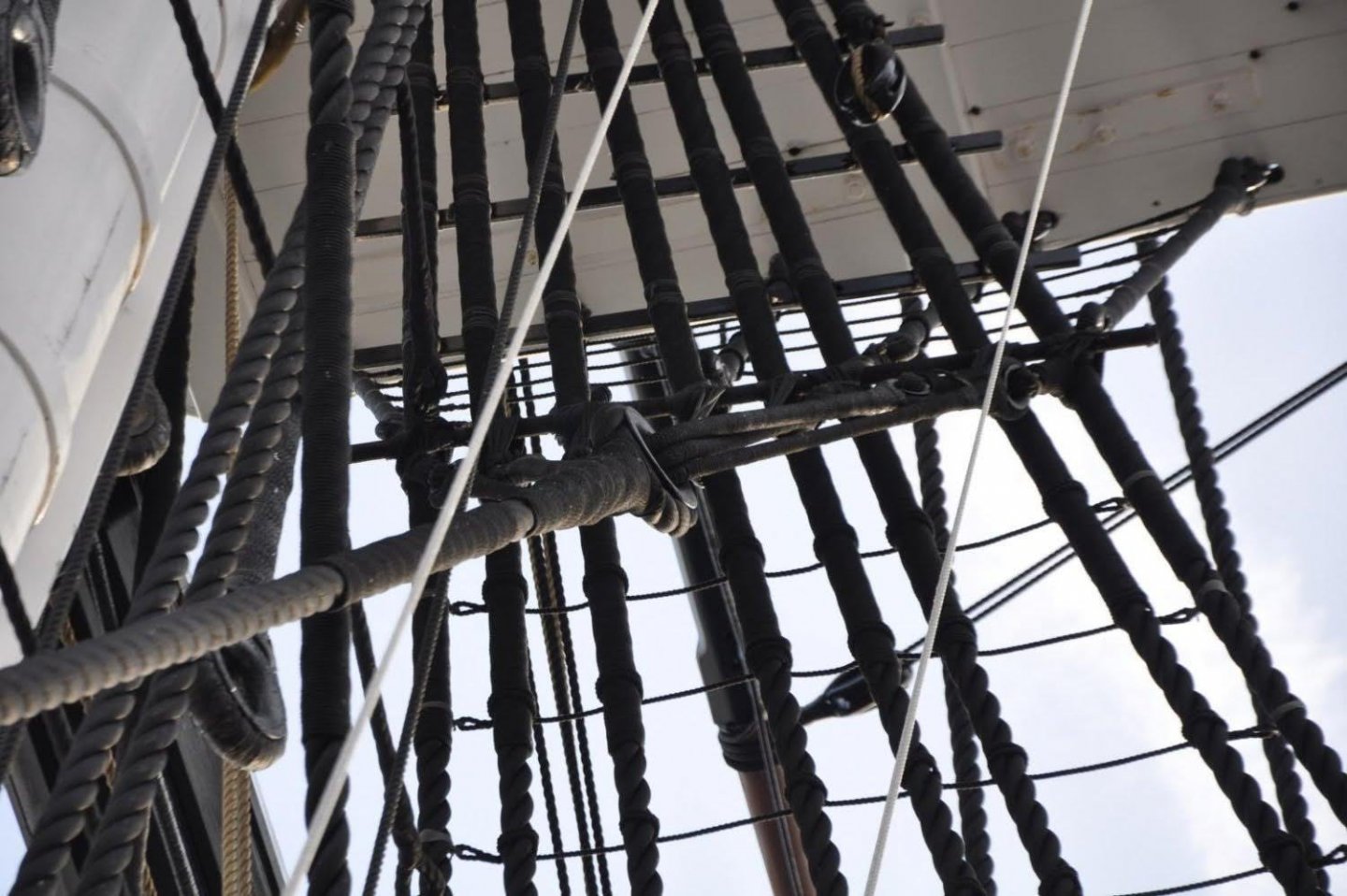

- 163 replies
-
- 4
-

-

-
- Model Shipways
- Constitution
- (and 2 more)
-
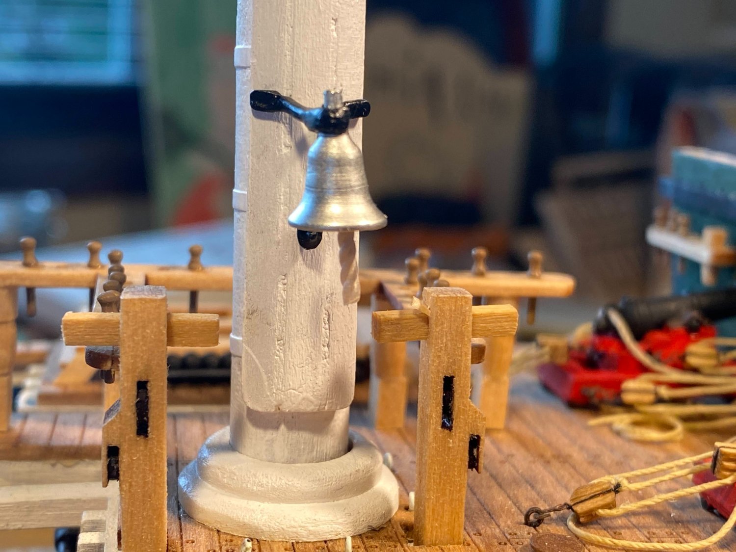
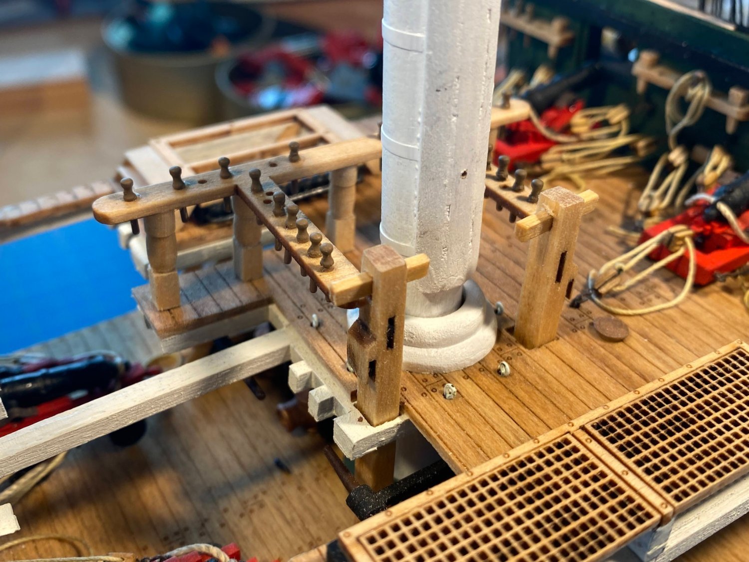
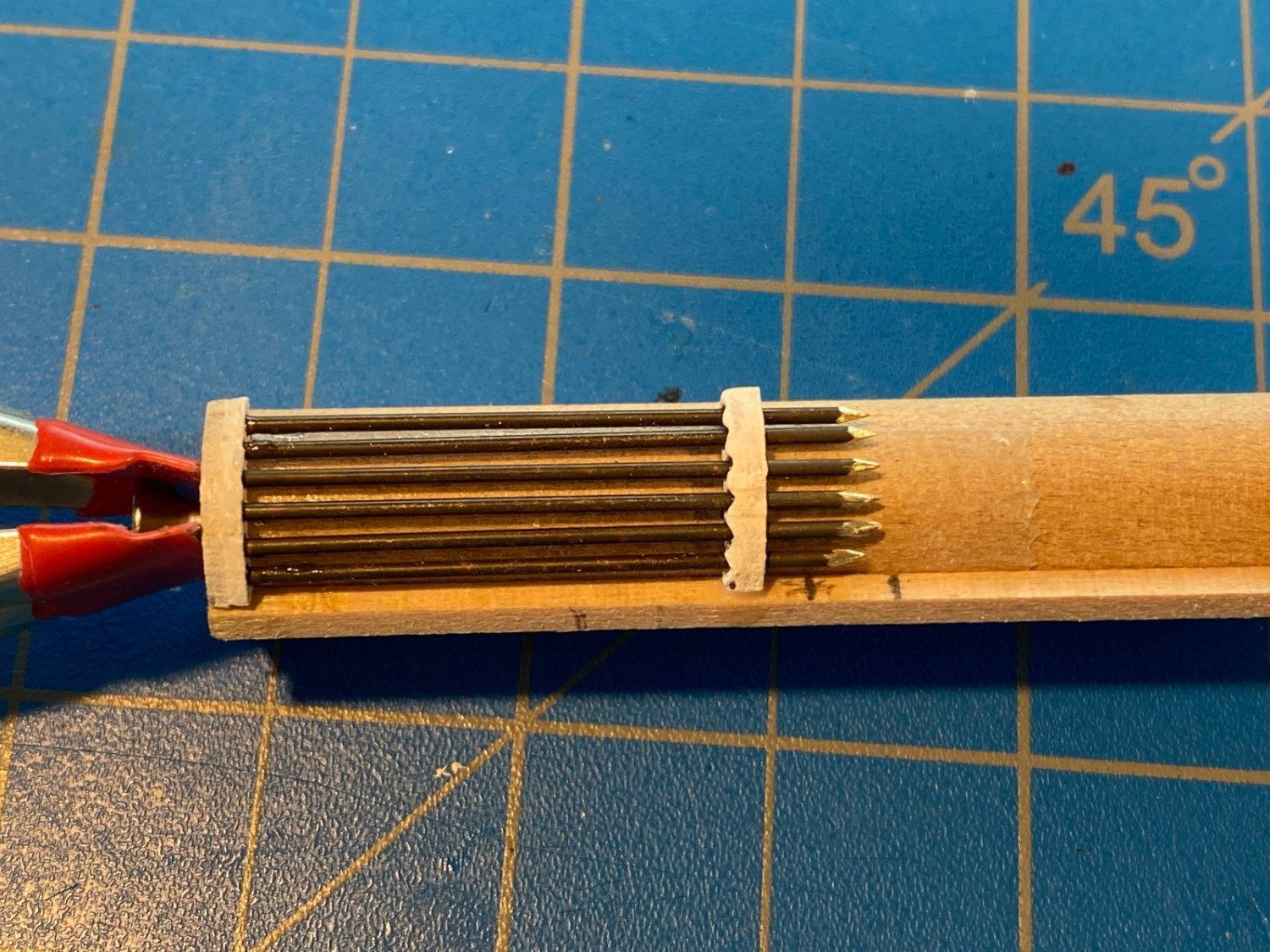
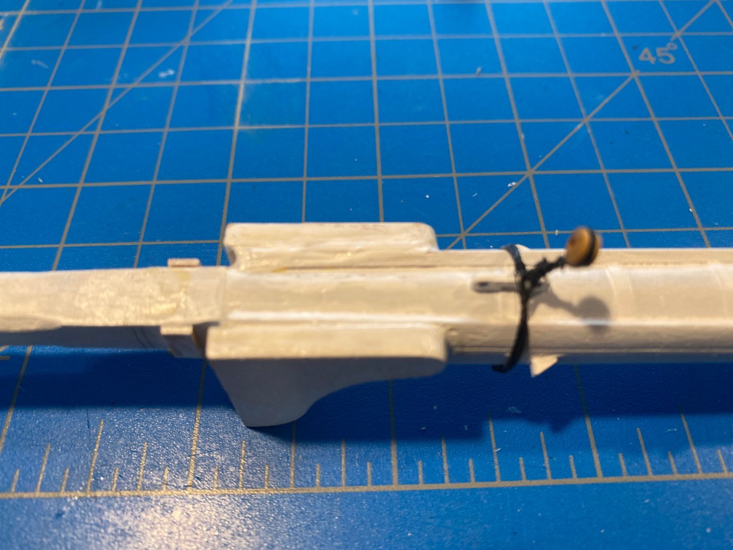
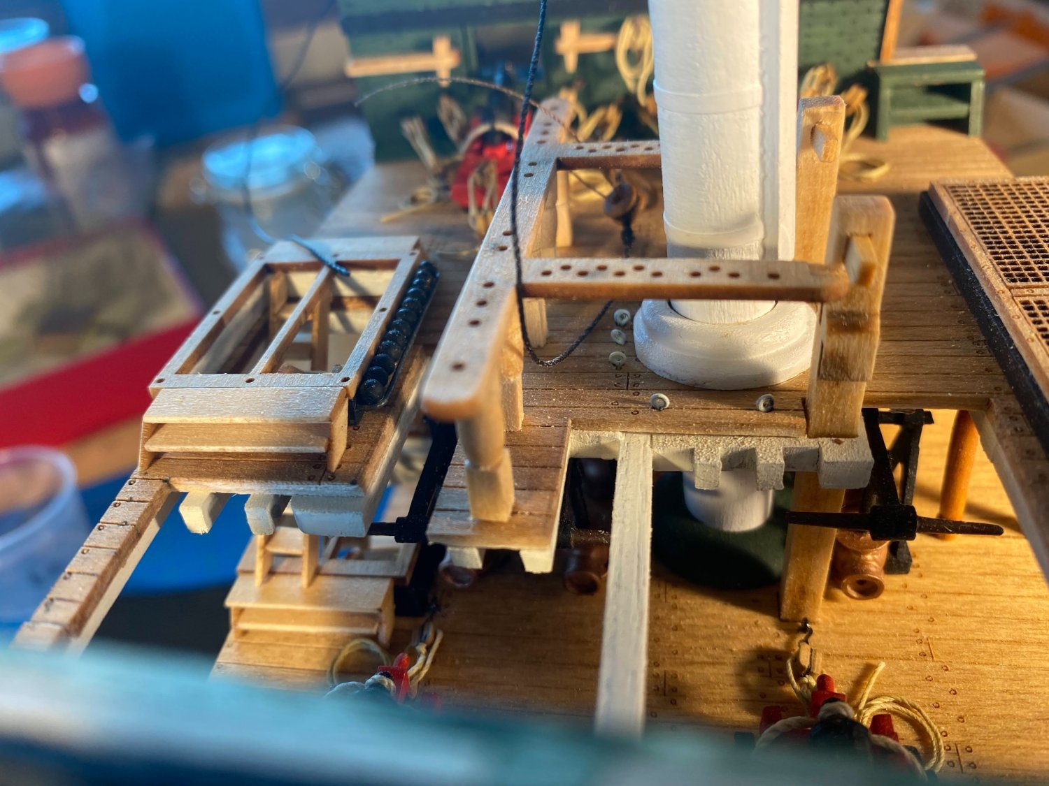
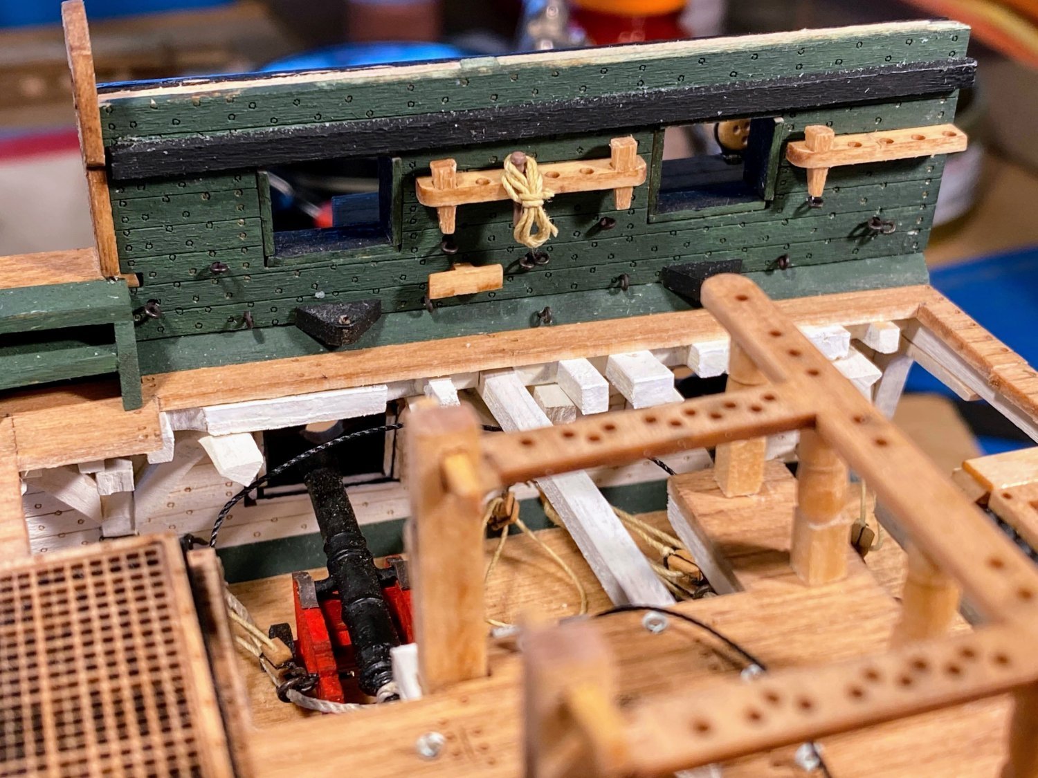
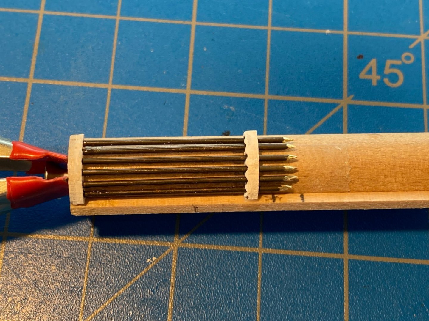
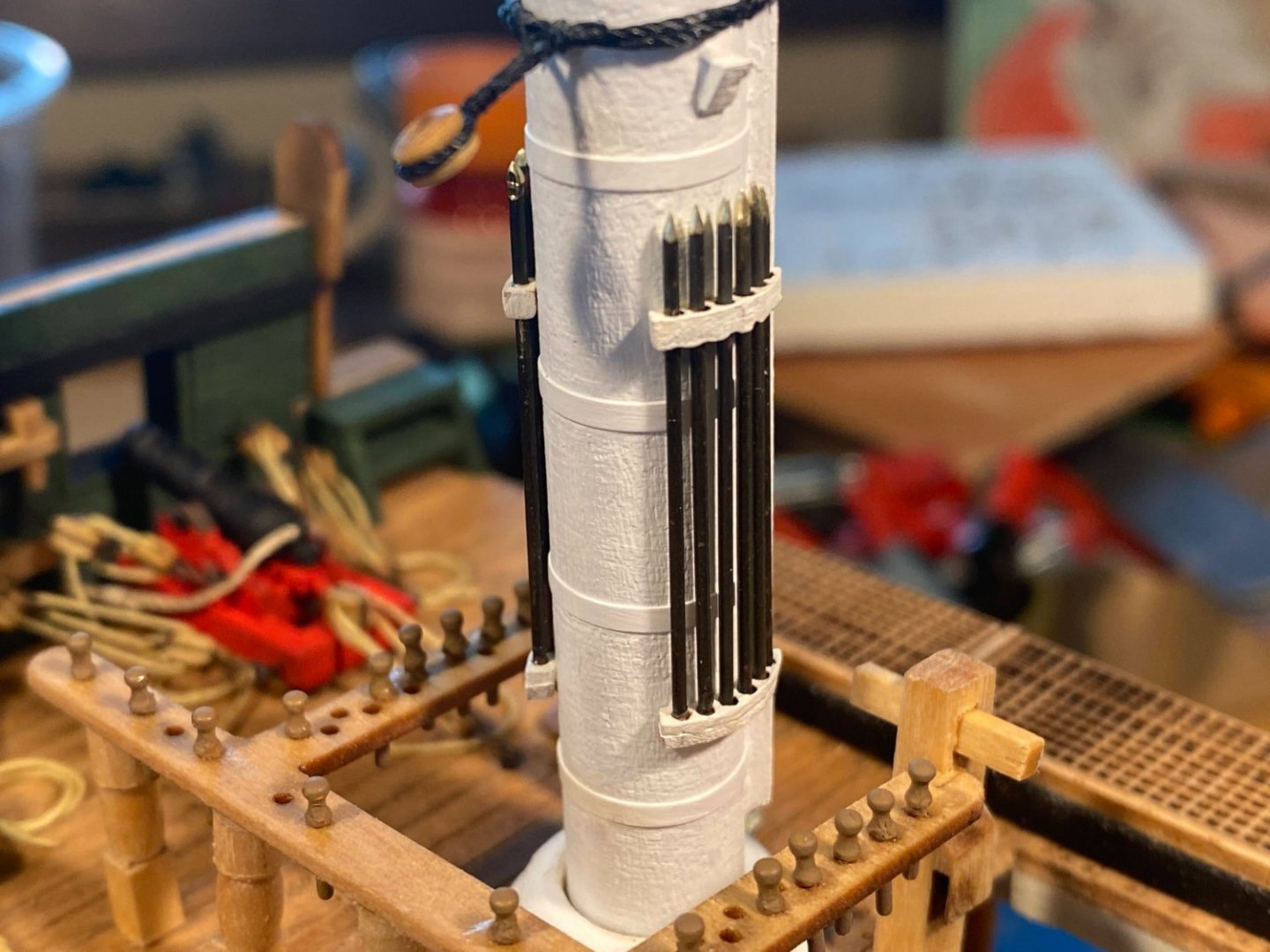
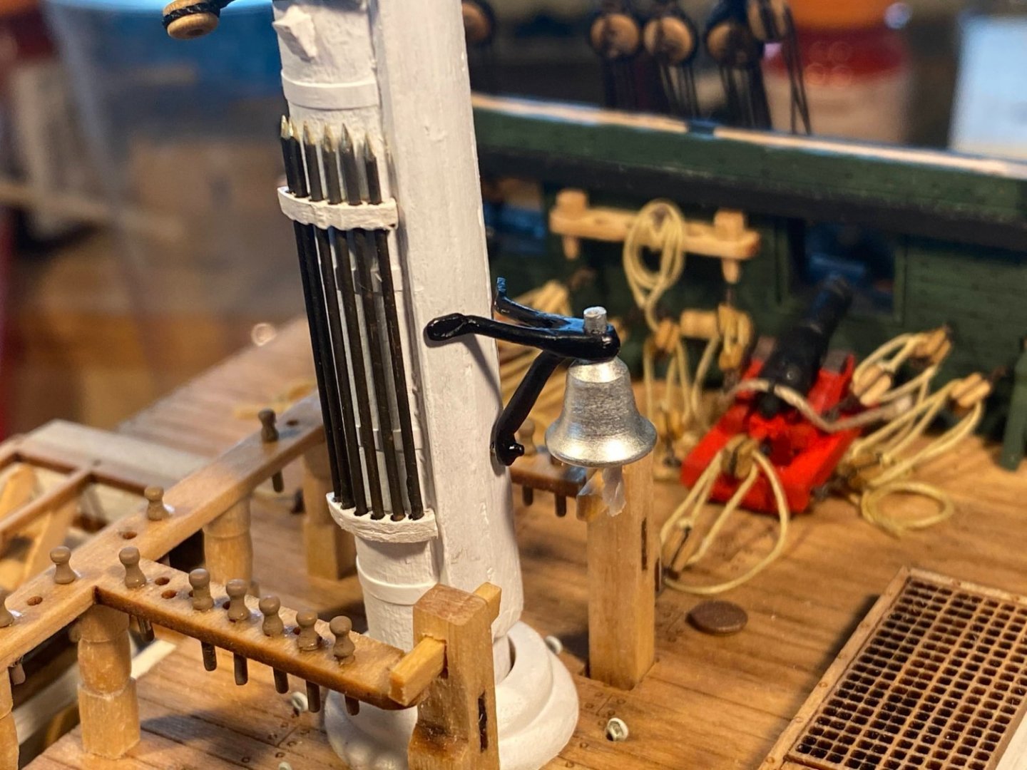
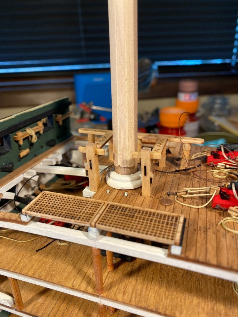
Some fun things I did while taking an occasional break from rigging shrouds and sheerpoles . . . Previously I installed three jackstay collars on the mast. Now I added the fourth, just above the fighting top. The bell and its bracket are Britannia metal. The instructions suggest polishing the bell, but I left it as is, thinking I probably can’t improve much on its shine. The bracket required quite a bit of bending to get it to fit right, and then I painted it black. I used some heavy string for the lanyard, and dipped it in diluted white glue to stiffen it and keep it from unraveling. The instructions direct drilling a hole inside the top of the bell’s cone, gluing an eyebolt in, and affixing the lanyard to the eyebolt. I simply turned the bell upside down, dripped a large drop of thick CA into what was now the bottom of the cone, and stuck one end of the lanyard into the glue, holding it long enough to dry. Then I glued the bell to the bracket, drilled a hole in the mast for the pin that is part of the bracket, and dry fit the whole thing in place for the picture below. I don’t think I’ll glue it in place until the rigging is complete. Next I painted about 30 (instead of the 50 suggested by the instructions) belaying pins with Tamiya’s Flat Earth. With a small drop of CA, I glued pins into all the holes where the plans show something will be belayed, plus a handful of additional holes. The belaying rail has two rows of holes on its fore/aft arms, but I fear that pins that close together will be very difficult to belay to, and I left the inner rows of holes empty. The hole in the mast for the bell assembly is visible in this photo. The boarding pike racks consist of a thicker, upper rack with holes in it, and two thinner racks (one with holes, one without) to be glued together as the bottom rack. The pikes themselves are made from pieces of 1/16” brass rod. The instructions suggest hammering the tip of each flat, then trimming it to form something like the tip of an arrow. No doubt in my mind that had I gotten my hammer out, I would have I would have i) missed the target entirely, ii) flattened more of the rod than intended, iii) flattened a thumb or finger, and iv) on rare occasions gotten it right. 🤪 I used a Dremel tool instead, slowly rotating the rod between my thumb and forefinger, while holding it against the spinning Dremel bit. With a little trial and error I get most of them right. The instructions suggest painting the tips shiny silver, but I left them bare, which is pretty shiny as is, and the fact that they are brass instead of the color of some other metal is hardly noticeable. I assembled the racks and pikes with a jig I made with the placeholder mast stub used earlier in the build, along with some double sided Scotch tape. I stuck a strip of wood to the tape on the “mast” for alignment, then stuck the brackets on. I slid each pike through the upper bracket, then applied a tiny drop of thick CA to the bottom of the pike and slipped it into its hole in the lower bracket. I then applied some diluted white glue to the bottom of the upper bracket and the pikes . . . of the various kinds of glue I use, diluted white seems to be the least visible when dry. After everything had dried, I carefully peeled the whole assembly off the jig and glued it to the side of the real mast. Meanwhile, work continues, slowly, on the futtock and bentinck shrouds.


- 163 replies
-
- 7
-
-
- Model Shipways
- Constitution
- (and 2 more)
-
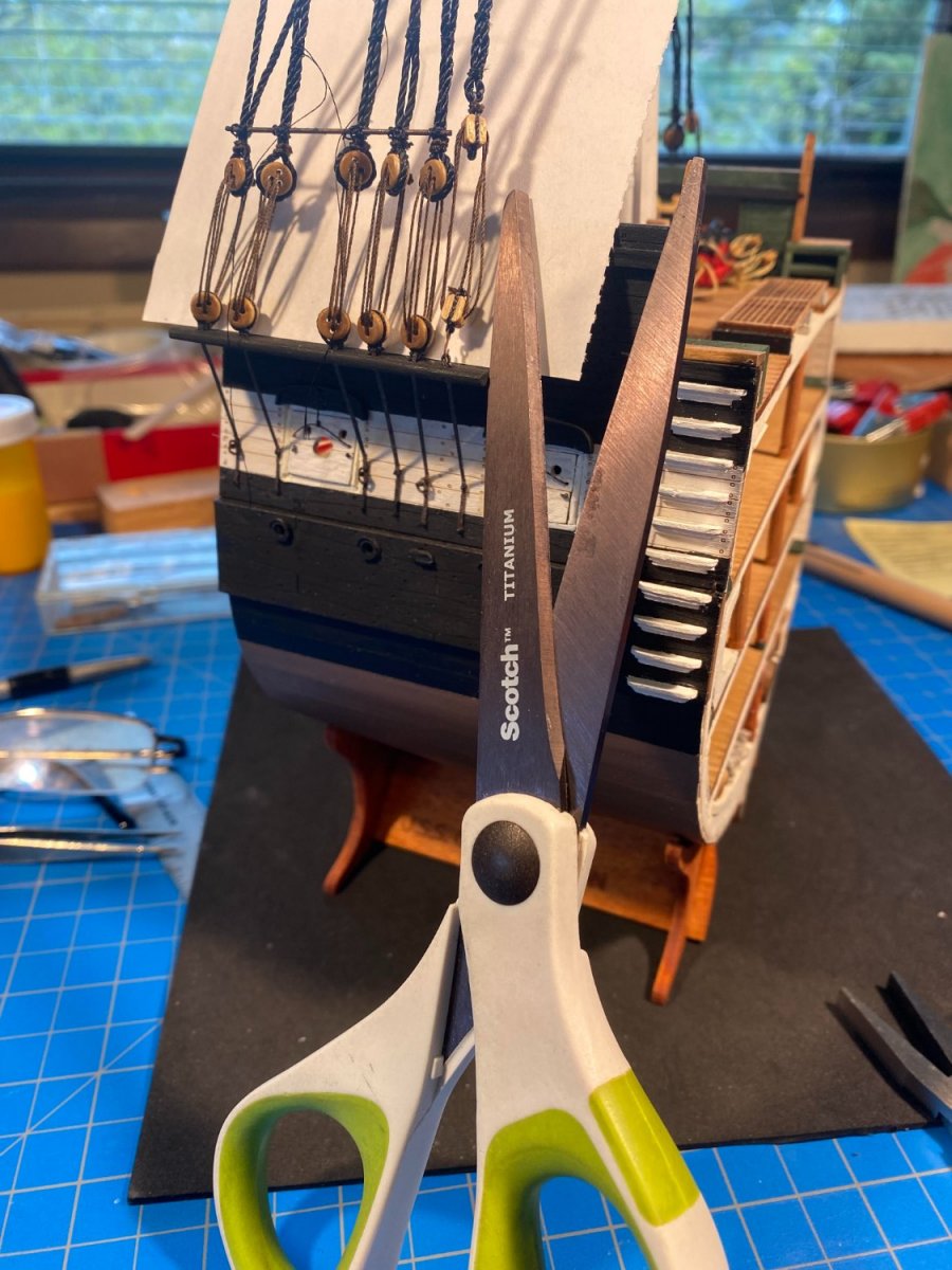
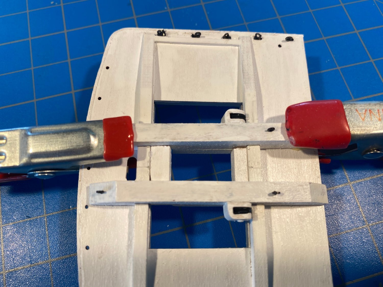
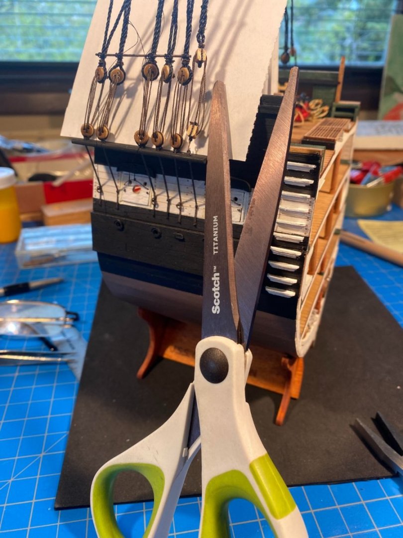
The sheerpoles are cut from 1/32” brass rod, which I darkened. Tying them to the shrouds was more of a challenge than it should have been. First of course you need two hands to tie any kind of knot (at least I do), and a third hand to hold the sheerpole to the shrouds. I found an inanimate hand for the latter, but I found myself occasionally snagging it with a shirt cuff or bumping the hull, fortunately with no worse damage than raising my irritation level. What seemed to work best was to lash the sherepole to the middle shroud first. Then before applying any glue, I slid it so that it was properly aligned at either end with the outboard shrouds. Having carefully cut the sheerpole to the proper length, that looked pretty good . . . until I realized that I couldn’t lash the sheerpole to the shrouds at either end if all I had to work with was a very small length of pole extending beyond the shrouds at either end. So I started over with a sherepole that was about 1/4“ or so too long, lashed it in the middle and both ends, slid it out so the extra length was all at the aft end, cut the excess off with wire cutters, then applied a healthy dose of diluted white glue after adding the other two lashings. Next project was cutting the tail ends of the shrouds to equal lengths and then seizing them to the standing part of the shroud. As mentioned in my last post, this would have been a lot easier if I had cut them when they were still flat on the work bench, easier to measure and to cut. I found that my usual thread cutting scissors didn’t work on the shrouds’ thick thread, nor did my Xacto knife (with a sharp blade) since there was nothing firm to cut against. What did work was a pair of office scissors, but it made me feel like I was working on my model with a chainsaw. On the port side I tried just eyeballing things, and I didn’t get them as even as I would have liked. The problem was that with those giant scissors, I had to pull the thread I was cutting away from everything else, losing sight of where the cut needed to be. On the starboard side, I took some beige thread and tied that where the cut needed to be, with better results. I also found seizing the two parts of each shroud together to be difficult, in large part because despite contacts, reading glasses and bright lights, the very thin black thread disappeared in front of the dark and black background. In one of those “why didn’t I think of that before” moments, I slid a white piece of paper in behind the deadeyes, which made the job a lot easier. While working on all of this tedious tying of knots, I took an occasional break to work on some other detail I hadn't finished previously. I'll put a post together about that sometime this weekend. I have also been giving a lot of thought lately to the futtock and bentinck shrouds, which I'm about to get started on. My thinking now is that I won't add the ratlines until after most or all of the running rigging is in place.


- 163 replies
-
- 5
-
-
- Model Shipways
- Constitution
- (and 2 more)
-
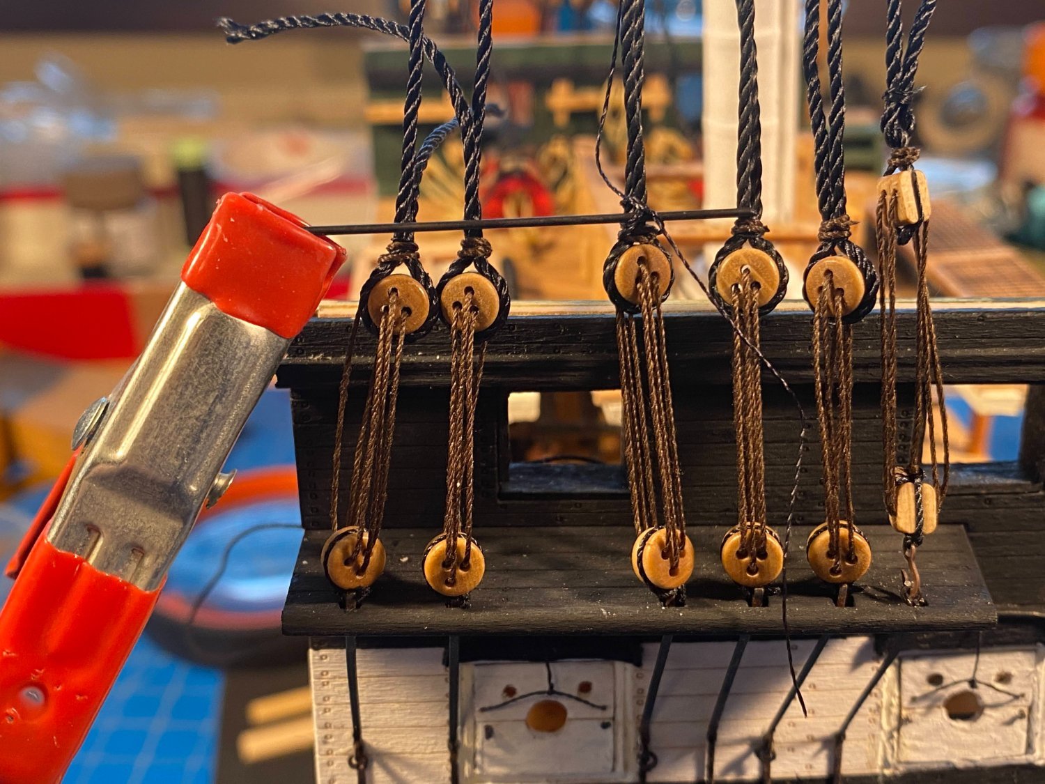
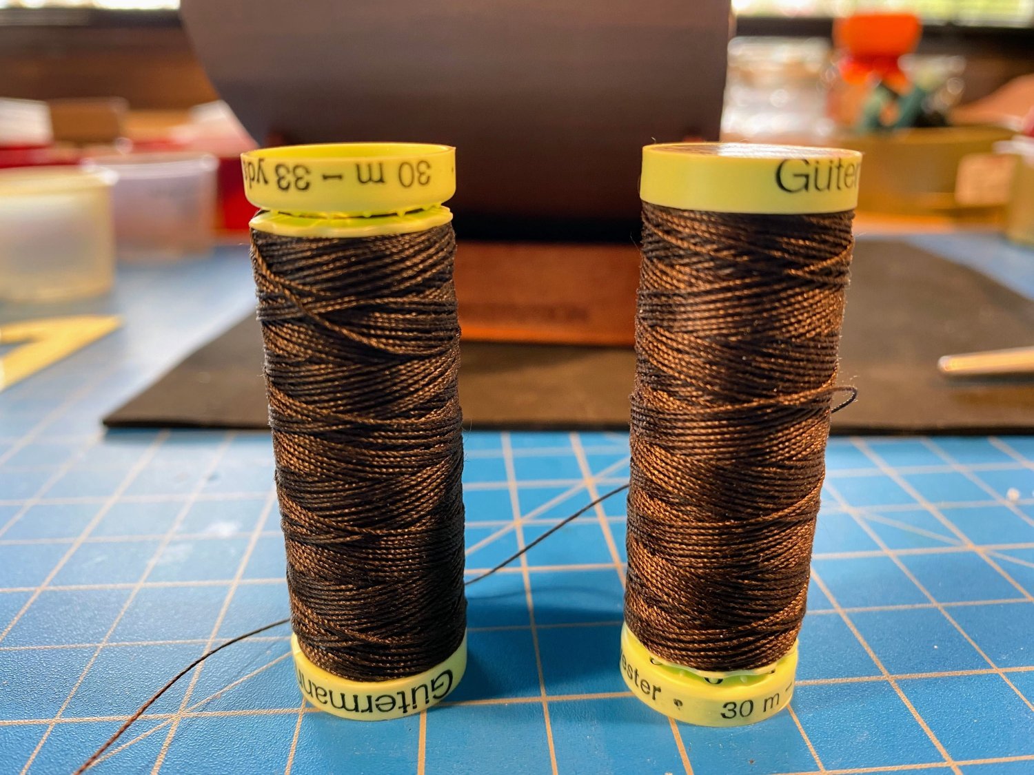
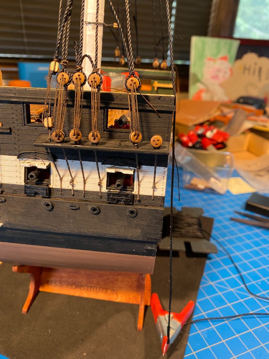
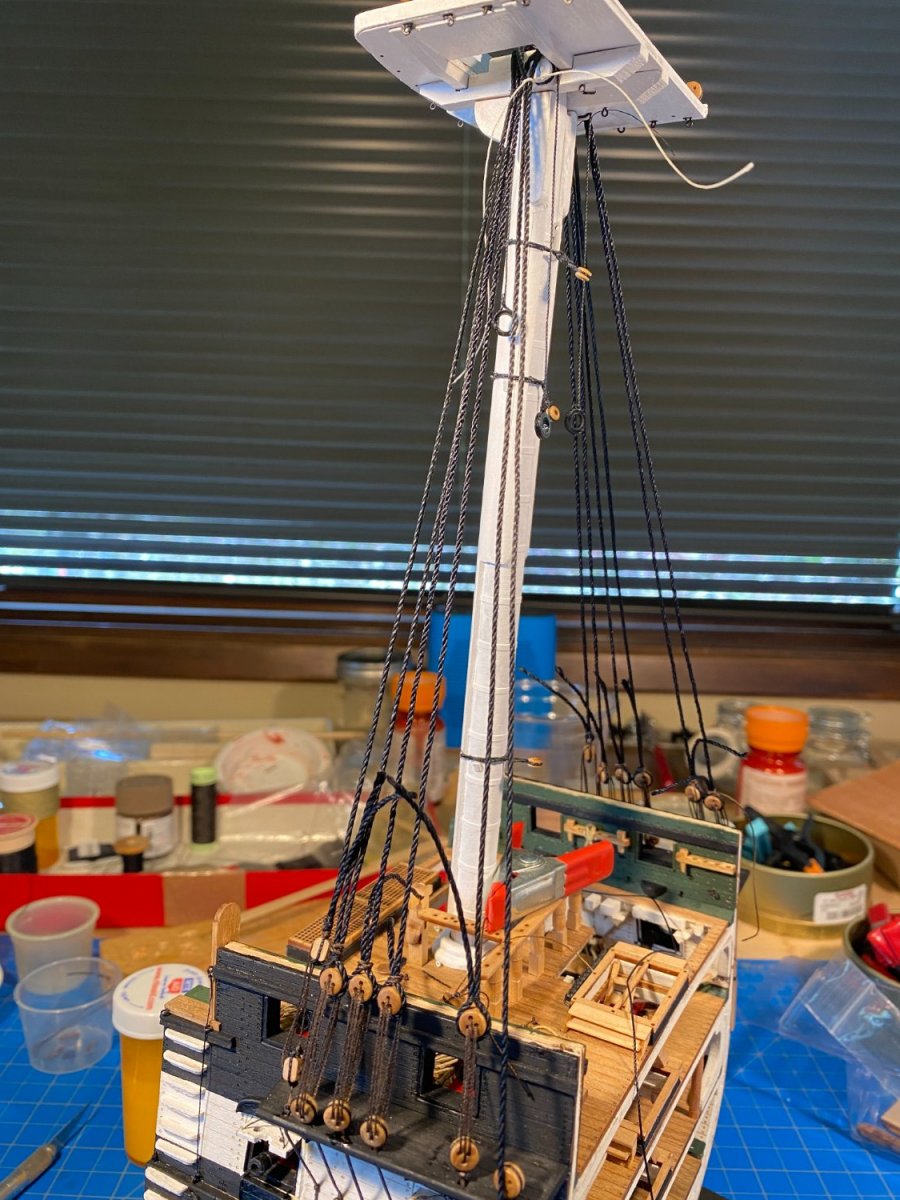
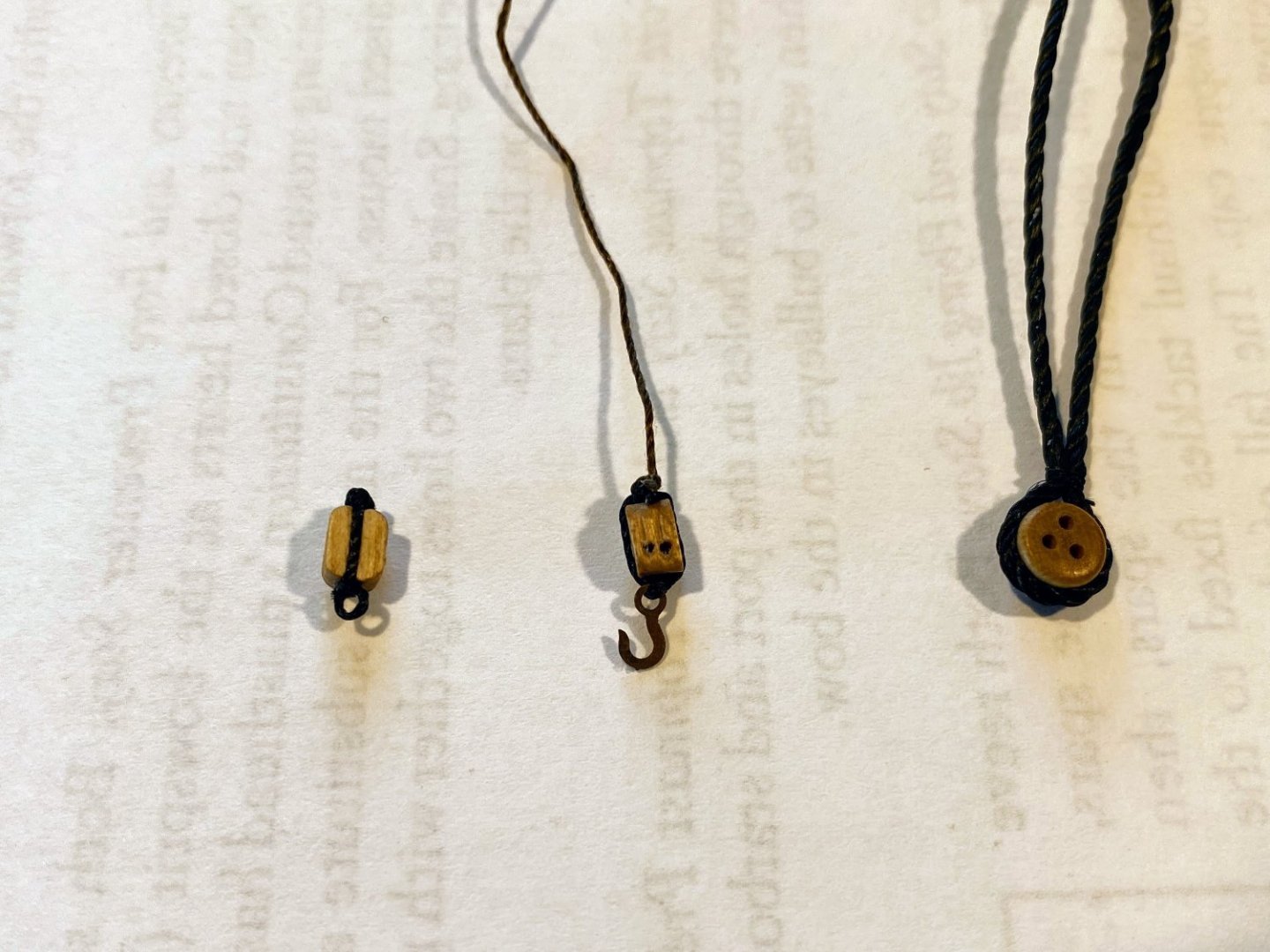
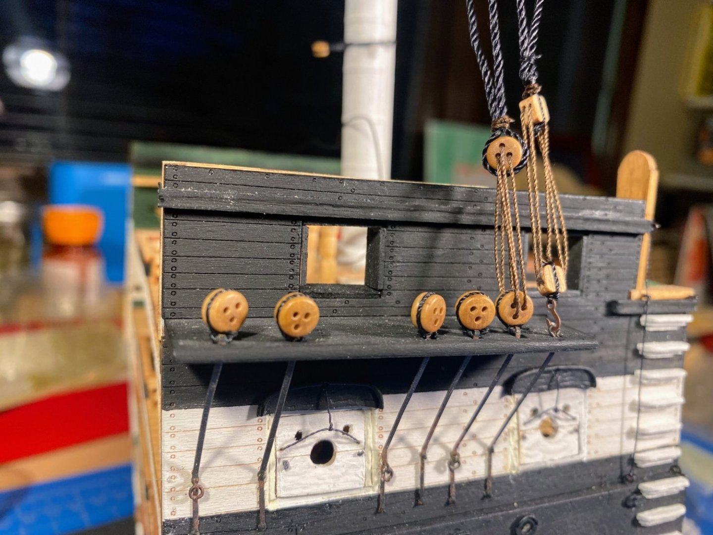
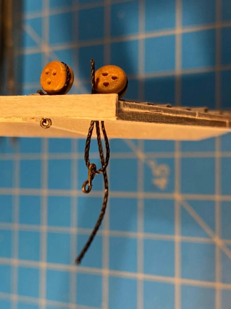
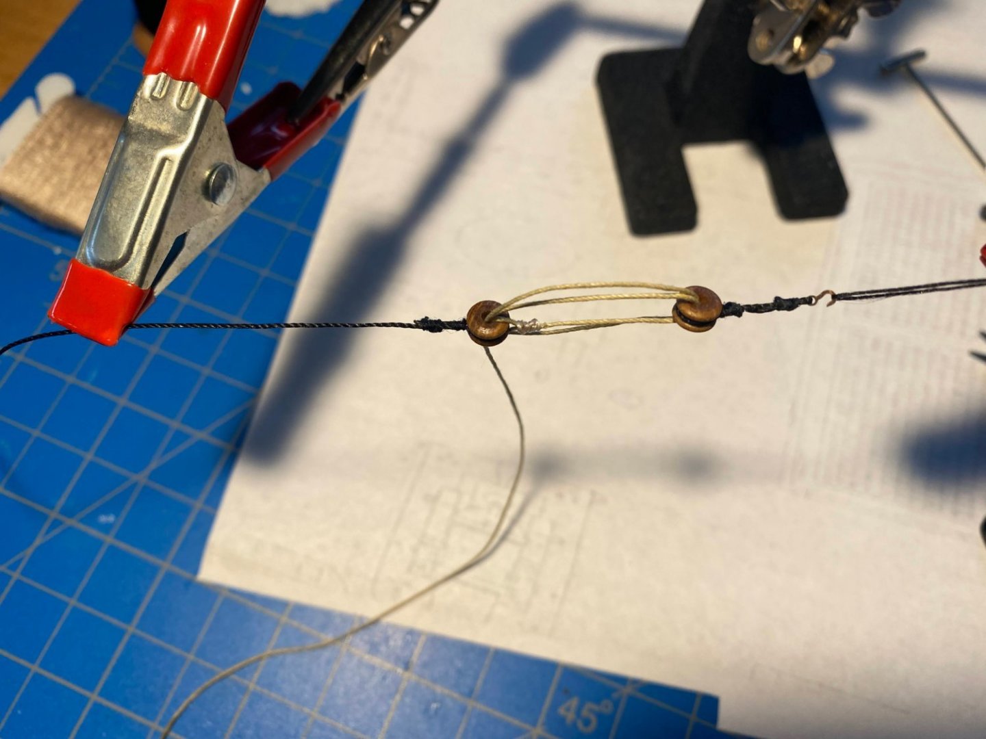
The lower mast is supported by six shrouds on each side; five connected to the hull with deadeyes and lanyards, and the sixth, the swifter, attached by a pair of blocks and lanyard. The swifter has what one might call adjustable standing rigging, as discussed in usedtosail’s build log of the entire Constitution (starting near the bottom of page 35 of his build log). Part of that discussion dealt with the appropriate color for such adjustable rigging, and the prevailing opinion was dark brown. On the current Connie the lanyards and deadeys are all black, but since I had left the deadeyes natural (a darkish brown), I made a trip to the local fabric store to find some dark brown thread of the appropriate thickness. I came home with the two spools of brown thread, thinking I probably would use the very dark shade. But looking at it next to the black shrouds, I was afraid it would be almost indistinguishable from them, and having gone to the trouble to find some brown thread, I wanted it to be a visible detail. In retrospect I think the darker shade might have been better, but I’m happy with what I did. The swifter is supposed to have a double block attached to the shroud and a triple block hooked to an eyebolt attached to the channel coming out of each side of the hull. Triple blocks are a bit of a problem on a model of this scale as they appear (to me) to be too large. The kit supplies a few 5mm triple (and double and single) blocks, and 5mm translates to 15 inches on the real thing. That’s one enormous block. I chose to use two 4mm doubles instead (the equivalent of 12”), which makes them about the same size as the deadeyes, which I think looks more accurate. The forward pair of shrouds consists of a deadeye, cable or thick line which runs up through the fighting top and around the mast, and back down as a swifter. The rigged deadeye, hook, blocks and shroud are shown in the second photo below, and shown rigged in the third photo. The middle and aft pairs are tricky to rig since the deadeyes should all run in a straight line. It took me some trial and error to get there, but this is the routine that ended up working best for me. It may not work for the topmast shrouds, but that's a challenge for another day. First I seized a deadeye to the end of one of the shrouds (.041” thread supplied with the kit). Then I lashed the deadeye to a deadeye attached to one of the chainplates. Then I ran the shroud up through the fighting top, around the mast, and back down to the other channel deadeye, where I tied a short piece of thread marking the spot where I wanted a deadeye to be seized to the shroud. I then brought the shroud back off the mast and seized the deadeye to it as marked by the thread. With the deadeye in place, I ran the shroud back through the fighting top and back down to the hull, and then lashed the deadeyes together. Before lashing them together, I used another piece of thread to temporarily tie the two parts of the shroud together just below the fighting top. Finally I seized the two shrouds together below the fighting top, replacing what was previously tied temporarily. The one thing I would have done differently, now that I’m a little farther along in the build, is that I would have trimmed the tail ends of the shrouds a measured distance above the deadeyes just after seizing the deadeyes in place. As I will describe in a later post, cutting the thick thread required some heavy duty scissors, and doing so once the shrouds were in place in such a way as to have them all the same length proved to be difficult.


- 163 replies
-
- 6
-
-
- Model Shipways
- Constitution
- (and 2 more)
-
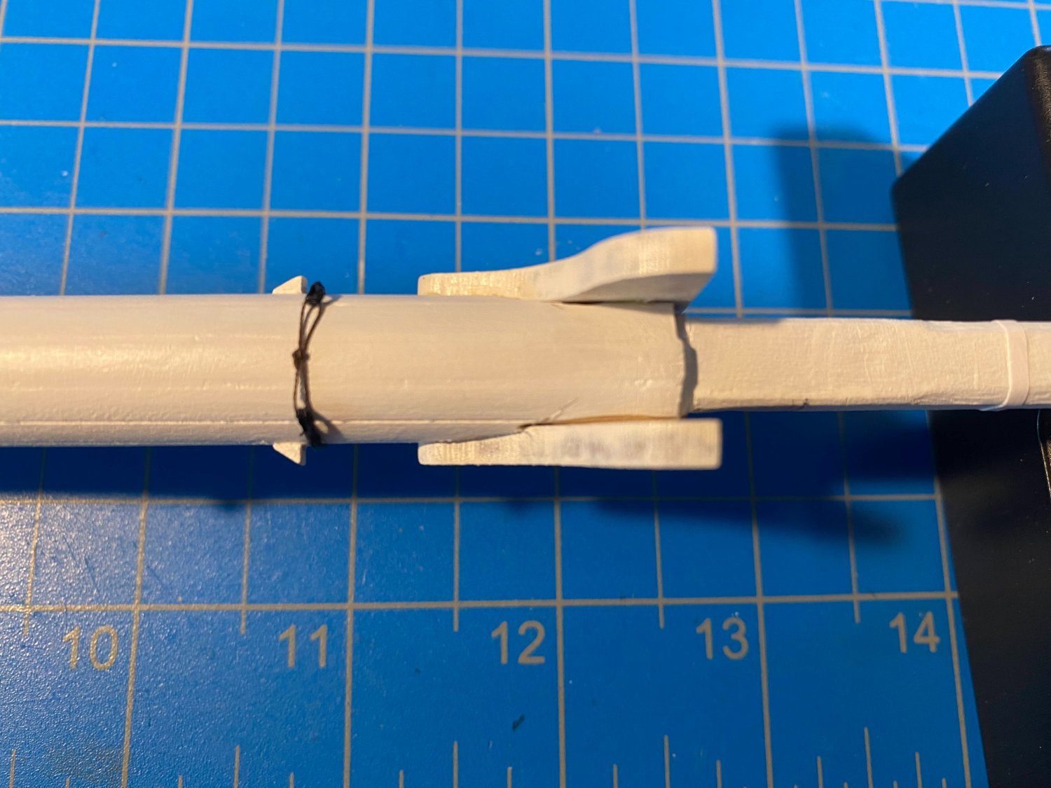
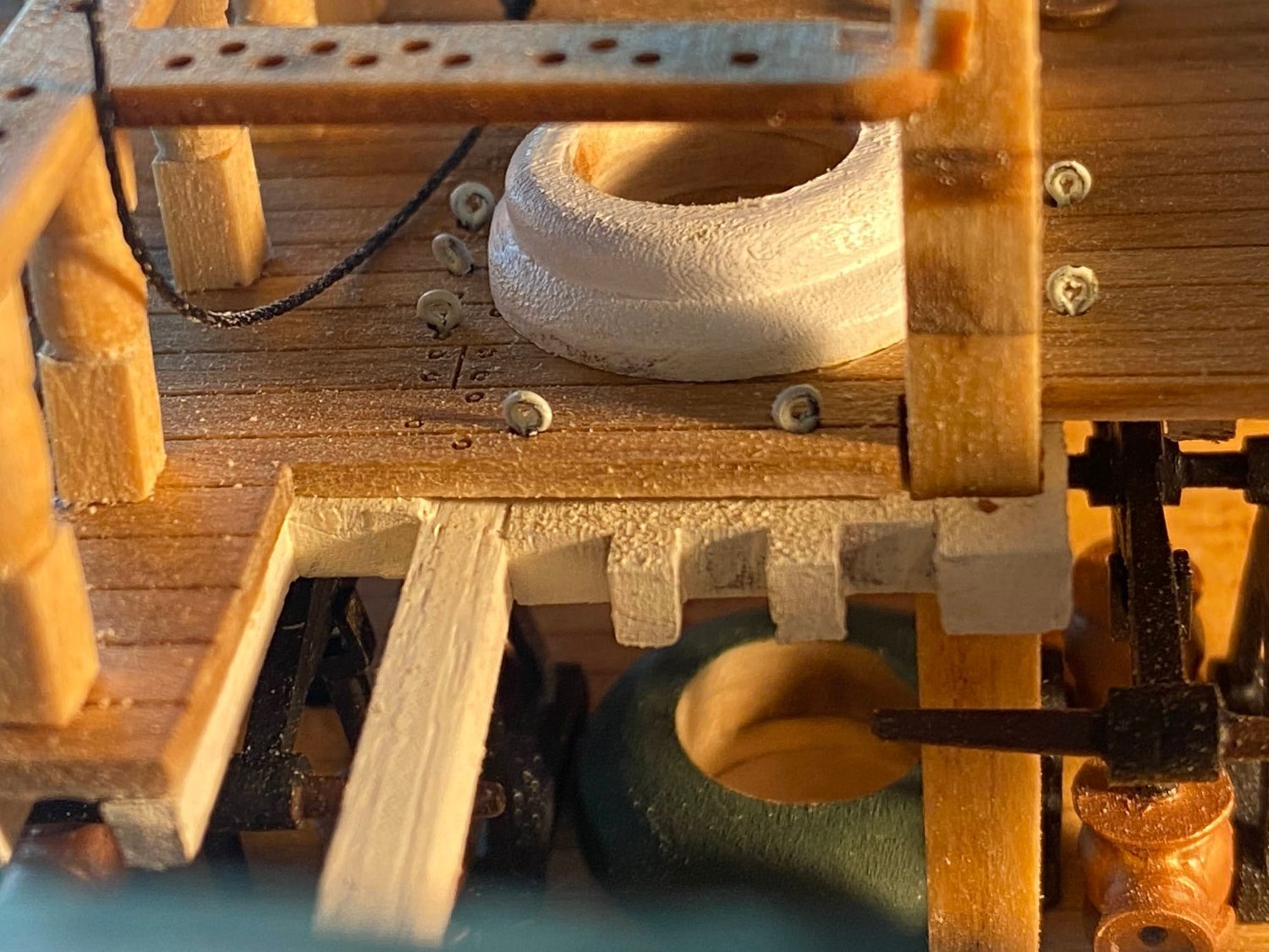
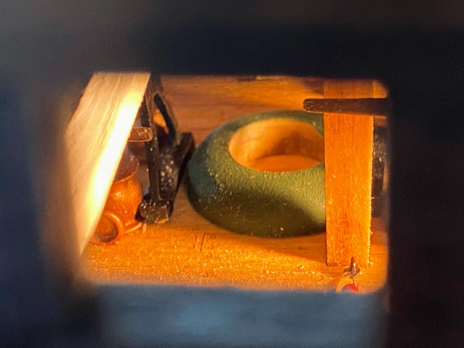
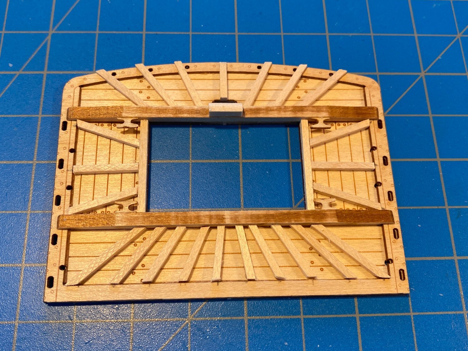
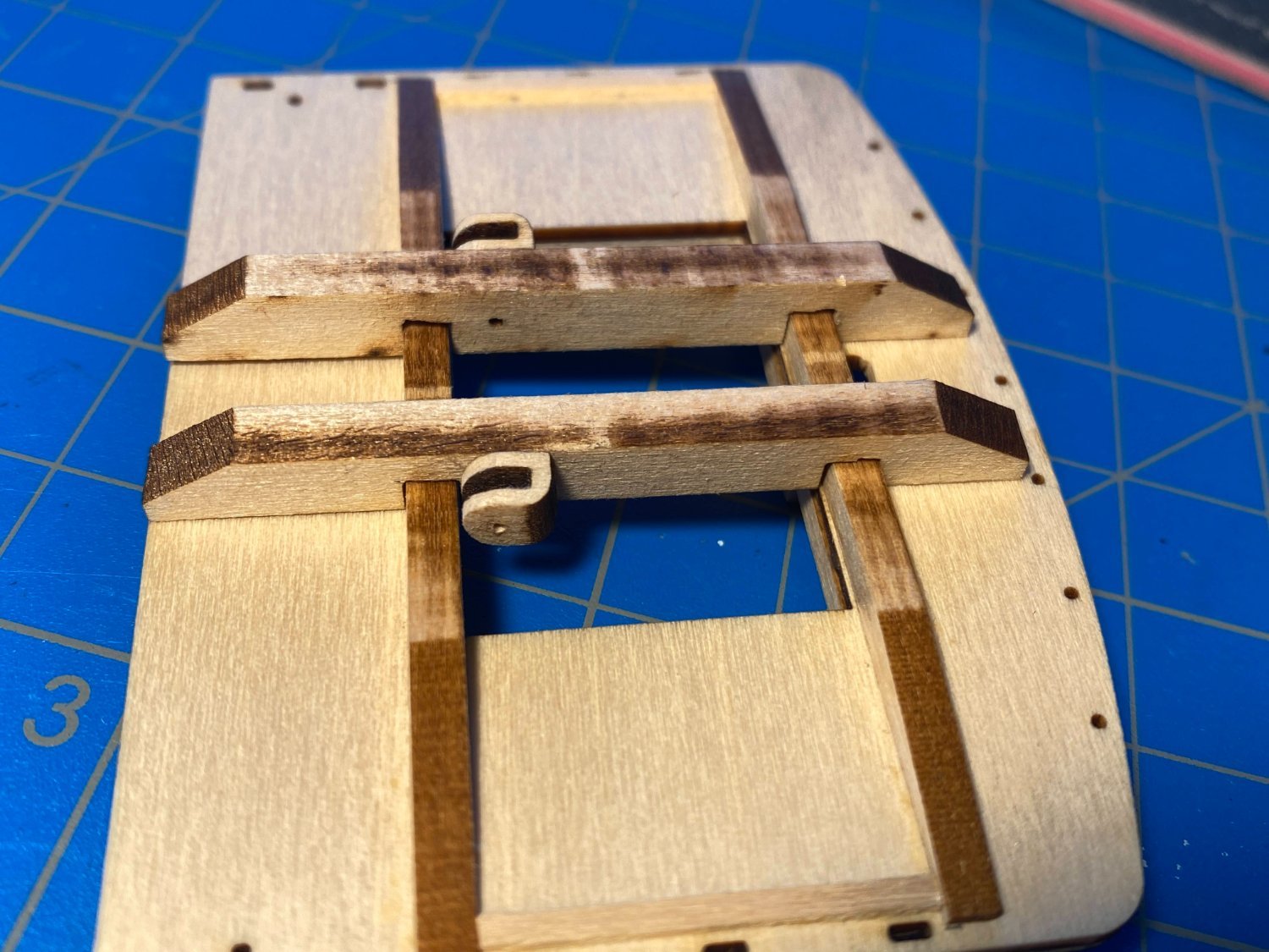
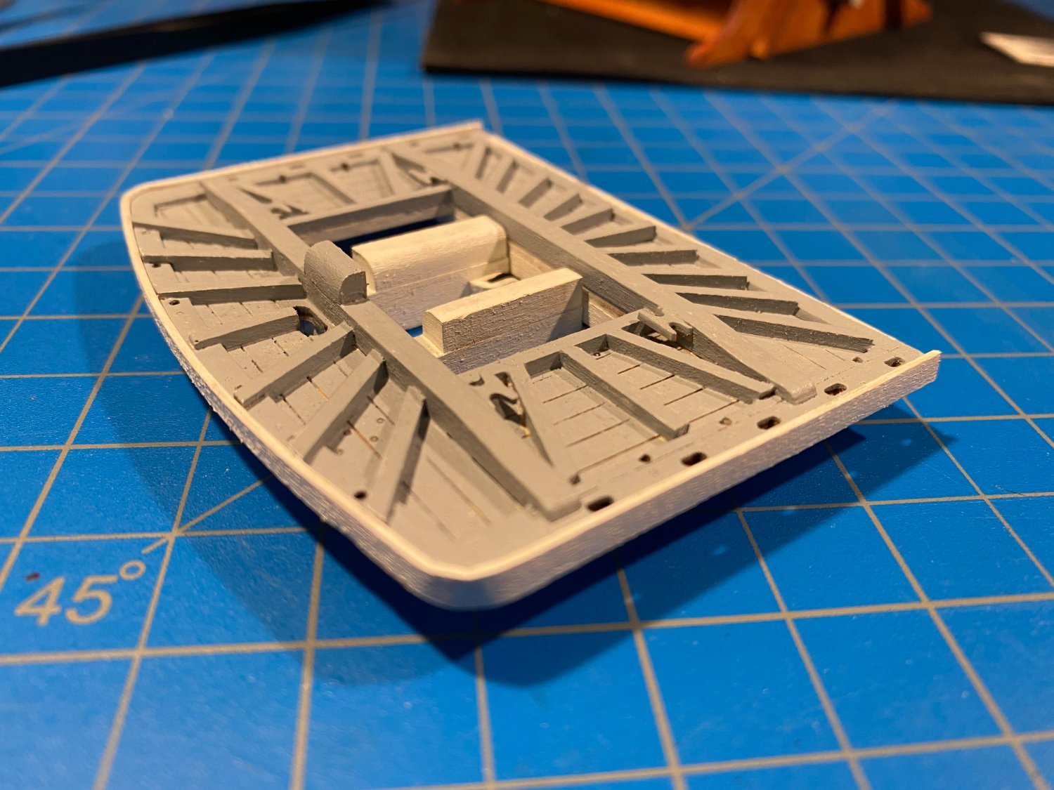
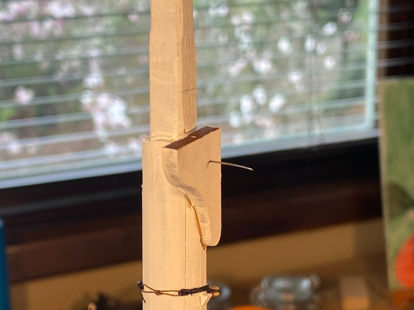
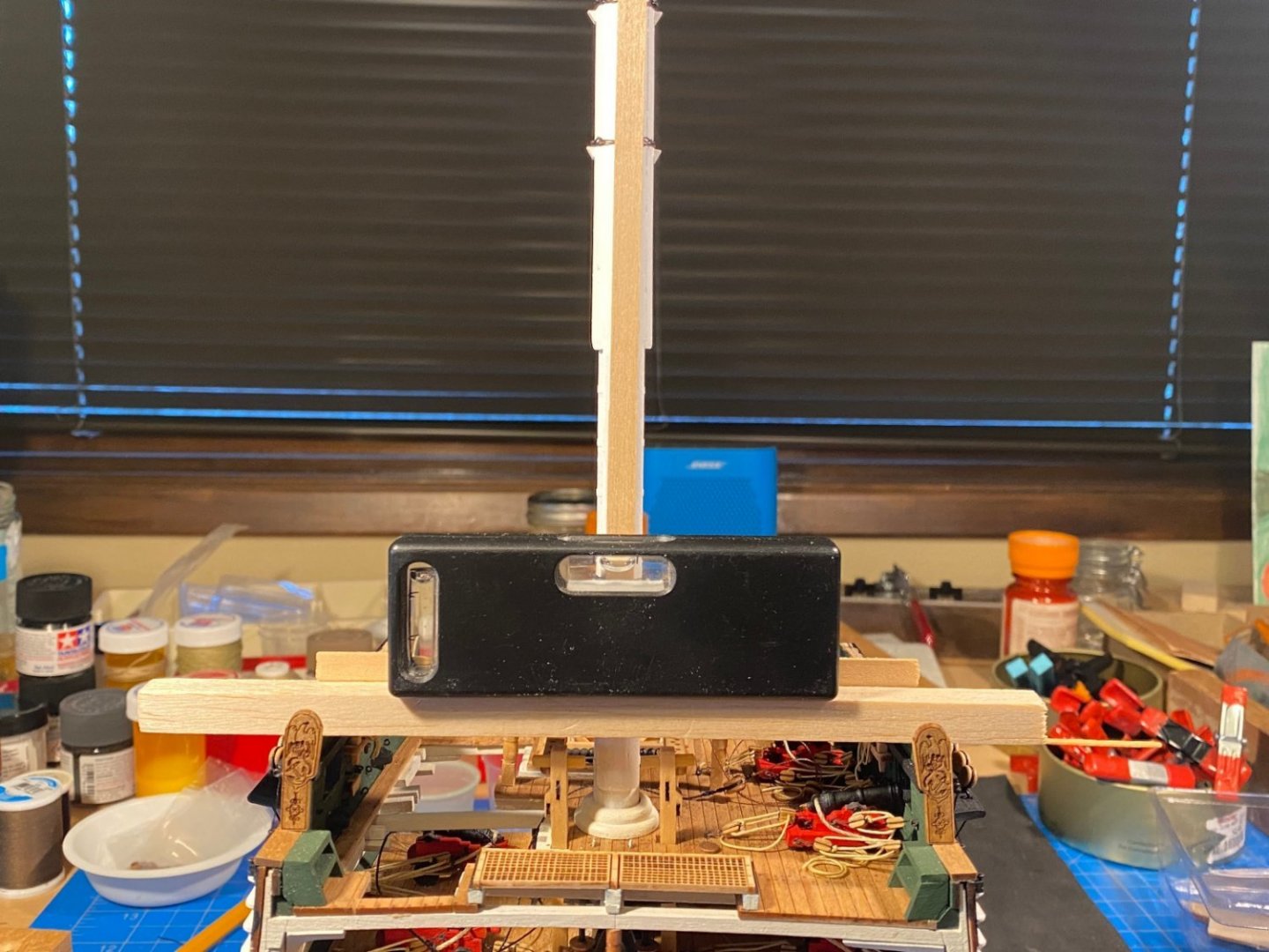
Two and a half weeks since surgery and all is well, especially since I am back to work on my build (but don’t tell my surgeon I probably don’t stand up from my workbench as often as I should). Next up . . . installation of the fighting top. I had not yet glued the trestle trees to the fighting top, wanting to see how the whole thing fit on the mast first. The instructions have you glue one trestle tree onto the cross trees 3/16” to one side of center, then glue in two 3/8” spacers, then glue the other trestle tree to the ends of the spacers and to the crosstrees. I did that, but only after giving quite a bit of thought to how to place the spacers. The spacers are cut from 1/8“ by 3/16“ stock (not supplied in the kit), which means they can be aligned horizontally or vertically. The written instructions are not at all helpful in terms of how these spacers are to be fit, but in the photos it looks like one is placed at the aft end of the hole in the fighting top, aligned vertically, and the other is placed forward of where the mast will be, aligned horizontally. The plans on the other hand don't show the spacers but appear to show the mast flush with the aft end of the hole in the fighting top. Taking a look at the Google Maps tour of the real thing, the aft side of the mast does appear to be some distance forward of the aft side of the hole, so consistent with the photos in the instructions, I glued one spacer to the aft side of the hole, aligned vertically. When I added up the dimensions of a vertically aligned spacer and a horizontally aligned spacer, plus the size of the lower mast, plus the size of the lower end of the topmast, it all added up to the length of the hole in the fighting top, which confirmed I was doing the right thing. The photo below may help make that paragraph somewhat comprehensible. Understand that the aft spacer is glued in place (between the cheek sheaves, or “thumb cleats” as named in the instructions) and the forward one is only dry fitted, to help me make the trestle trees parallel. That forward spacer will one day be glued farther aft, creating the appropriate amount of space between the top of the lower mast and the bottom of the topmast. Now time to affix the laser cut cheeks to the mast. This is a bit of a challenge, as flat surfaces need to be carved out of the round chafing protector, which wraps around most of the mast at this height. I mostly used a wireless Dremel tool to do the work, and did an abysmal job on the first try (starboard side), as can be seen in the first picture below. I filled the gap with a small piece of wood, a lot of glue, and some wood filler, and hid the mess with a coat of paint. Looking at the cheeks from the forward side looks a lot better. But there is a lot more to this story, and a lot of work needing to be done to properly glue the cheeks to the mast as pictured above. The fighting top needs to be (nearly) perfectly aligned in three respects. Looking at it from the side, it needs to be horizontal, that is, parallel to the water line (assuming the water line is horizontal) but not perpendicular to the mast, given the mast rake. It also needs to be horizontal looking at it from the bow or stern, that is horizontal athwartship. And looking at it from above, it needs to be aligned fore and aft, and not twisted relative to the mast. And since the mast rests on the cheeks, all this alignment is accomplished by careful placement of the cheeks on the mast. Oh, and it will all look best if the cheeks are parallel to each other. This is all complicated by the fact that the space between the fighting top’s trestle trees is 3/8“ and the mast at this height is 1/4“ square, meaning that there is nothing to firmly affix the fighting top to other than the cheeks. I remedied that problem by adding 1/32“ shims on either side of the mast above the cheeks, as can be seen in the second photo above (but not yet attached in the photo below). Now the fighting top could be firmly dry fit to the mast and aligned properly as described above. To accomplish all of this, I first dry fit the port cheek to the mast (the port side being where I did a much better job with the cut out). I held it in place with a pin made from some thin wire. Then I dry fit the fighting top, first properly aligning it as described above, and then aligning the cheek with the port trestle tree. Only then did I glue the port cheek to the mast (but not to the fighting top). Then after checking to be sure the fighting top was still properly aligned in all respects, I glued the starboard cheek to the mast. I then pulled the mast out of the ship, did the filling and painting described above, and took the pictures above. That accomplished, I put the mast back into the hull and glued the fighting top to the cheeks and to the mast, again making sure it was all properly aligned. Now looking for something easy to do, I rigged and attached the Burton Pendants (thank you JSGerson for your March 8 post above for explaining what they are). Only then did I remember to start taking pictures again.


- 163 replies
-
- 3
-
-
- Model Shipways
- Constitution
- (and 2 more)
-
Hobie Cat by phebe - Dumas
Tomculb replied to phebe's topic in - Kit build logs for subjects built from 1901 - Present Day
Great work Phebe! A lifetime ago I lived in Hawaii and raced Hobie 16s, like the model, then Hobie 18s. Definitely an exciting pastime. Your beautiful model brings back some wonderful memories. Thanks -
Very nice work. Like you, I found the upper gun port lids to be unacceptable as supplied and therefore made my own. And my kit was missing the photo-etched hinges, had insufficient chainplates, didn't have the very thin wire and included that odd decal! I asked MS to send me hinges and additional chainplates, and I only got the latter. I really like the way you did the hinges. I don't know whether painting them white would make them more historically accurate, but leaving them black makes them more noticeable in a very credible way.
-
Artesania Latina, S.A. Micro Shapers A, B & C
Tomculb replied to BubbleHead's topic in Modeling tools and Workshop Equipment
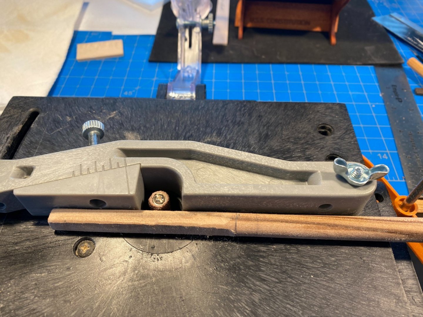
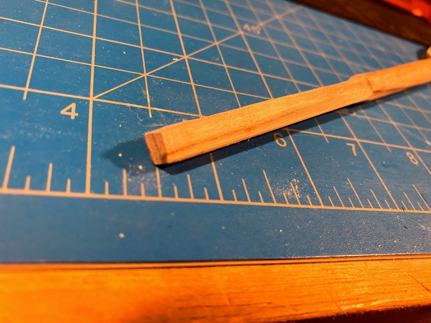
I bought them a few months ago and generally found them to be a mixed bag. Assuming you have wood strips cut in fractions of an inch rather than millimetres, you'll find them a lot easier to work with if you have a strip where the US measurement is close to a metric one. I was lucky in that regard for most of what I needed them for. In that case they work very well. Much harder to keep the strip centered if it has a lot of room to move back and forth within the slot in the tool, but maybe you can make some shims to create a good fit. -
Your attention to detail is amazing. Keep up the good work.
-
Thanks Jon (I hope I'm remembering your name correctly). I'm pretty happy with my build so far, but it pales in comparison to the masterful job you're doing on your Connie. I enjoyed the recent discussion about coppering. As mentioned before in this blog, I have avoided copper plating because most approaches I have seen simply don't look realistic; more "impressionable" approaches discussed in your blog may change my mind. But maybe the real problem for me is having to overcome laziness. I doubt that I'll ever have the patience you have to devote so many years to one model (5 so far by my count, plus 22 pages of blogging, and you're still working on the hull!!). Kudos to you. I'm very fortunate that my lower back journey has been much less arduous than yours. I started having issues about 25 years ago, but PT, stretching, lots of exercise, injections, etc. all helped keep symptoms very manageable and avoided any surgery. But loss of strength in one leg detected last fall led a few days ago to the removal of a little bone and a lot of arthritis; fortunately no fusion or artificial parts. With some luck, you'll finish your Connie before I need surgery again. Biggest challenge in my recovery now is tempering my annoyance when my wife admonishes me about bending, twisting and sitting too long. 😀
-
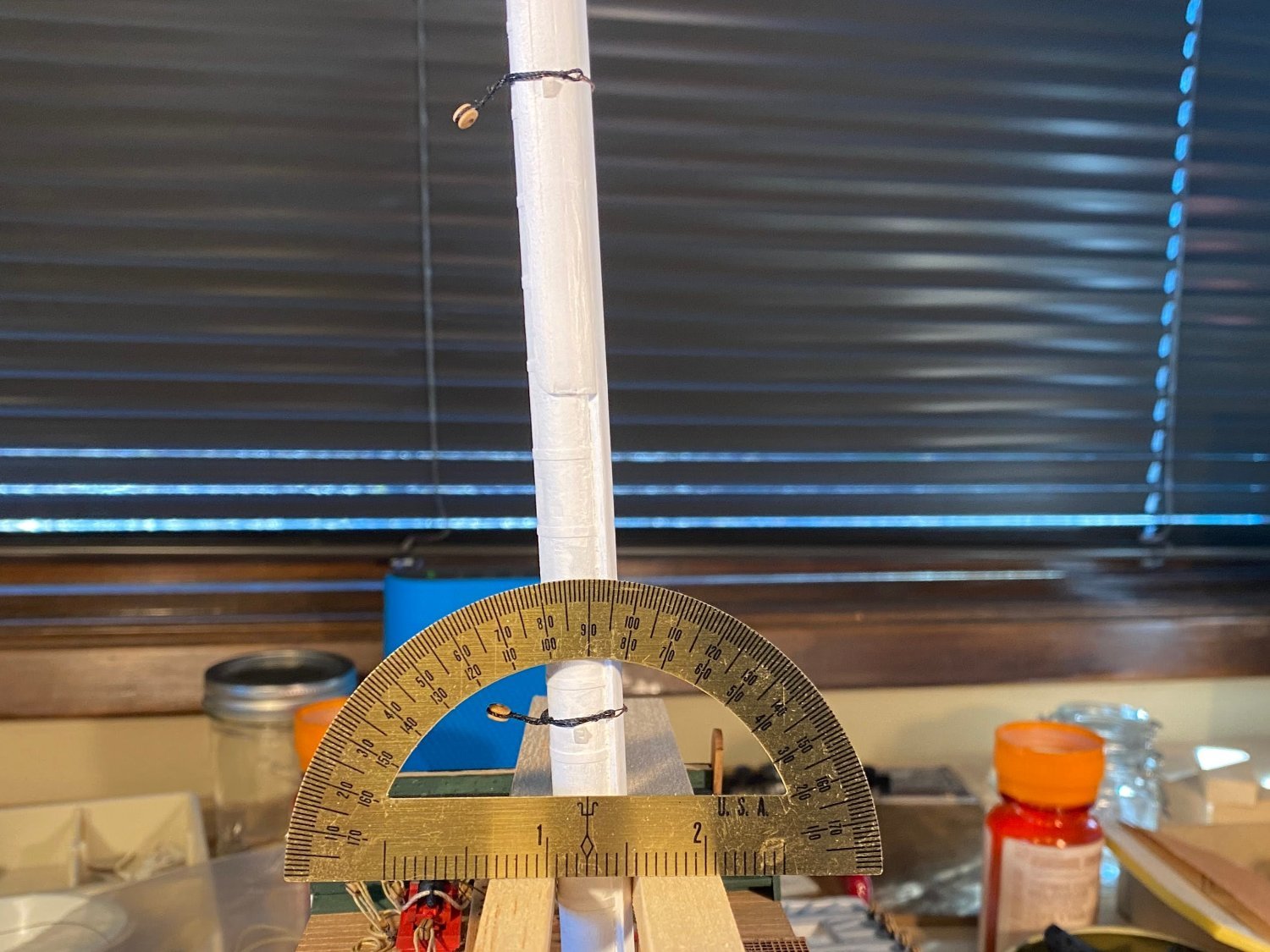
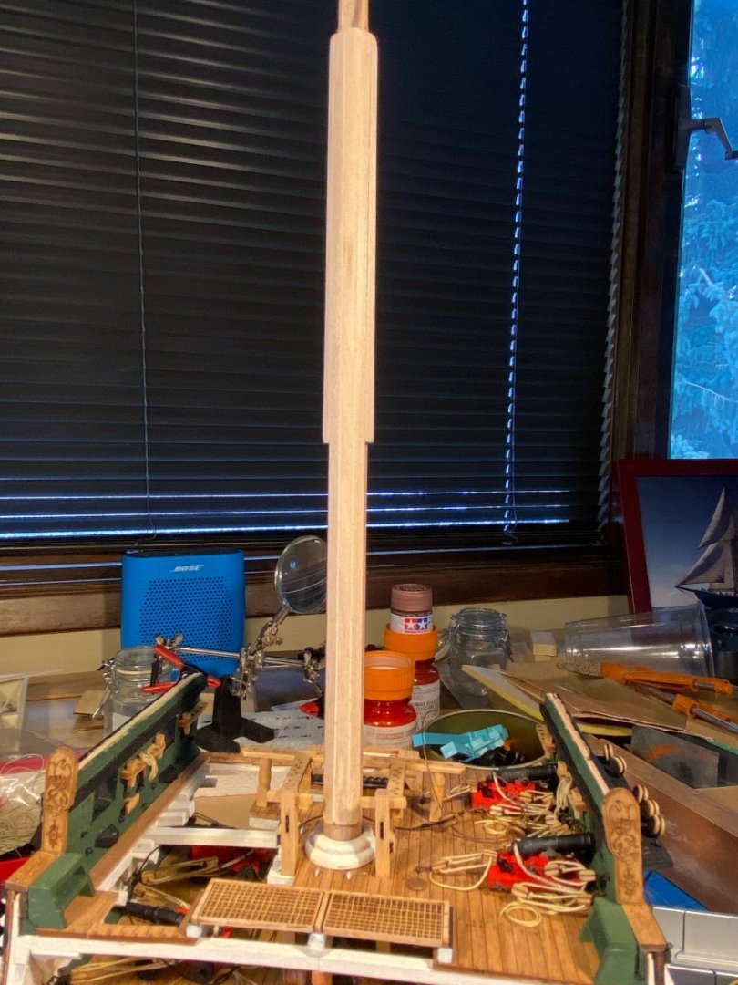
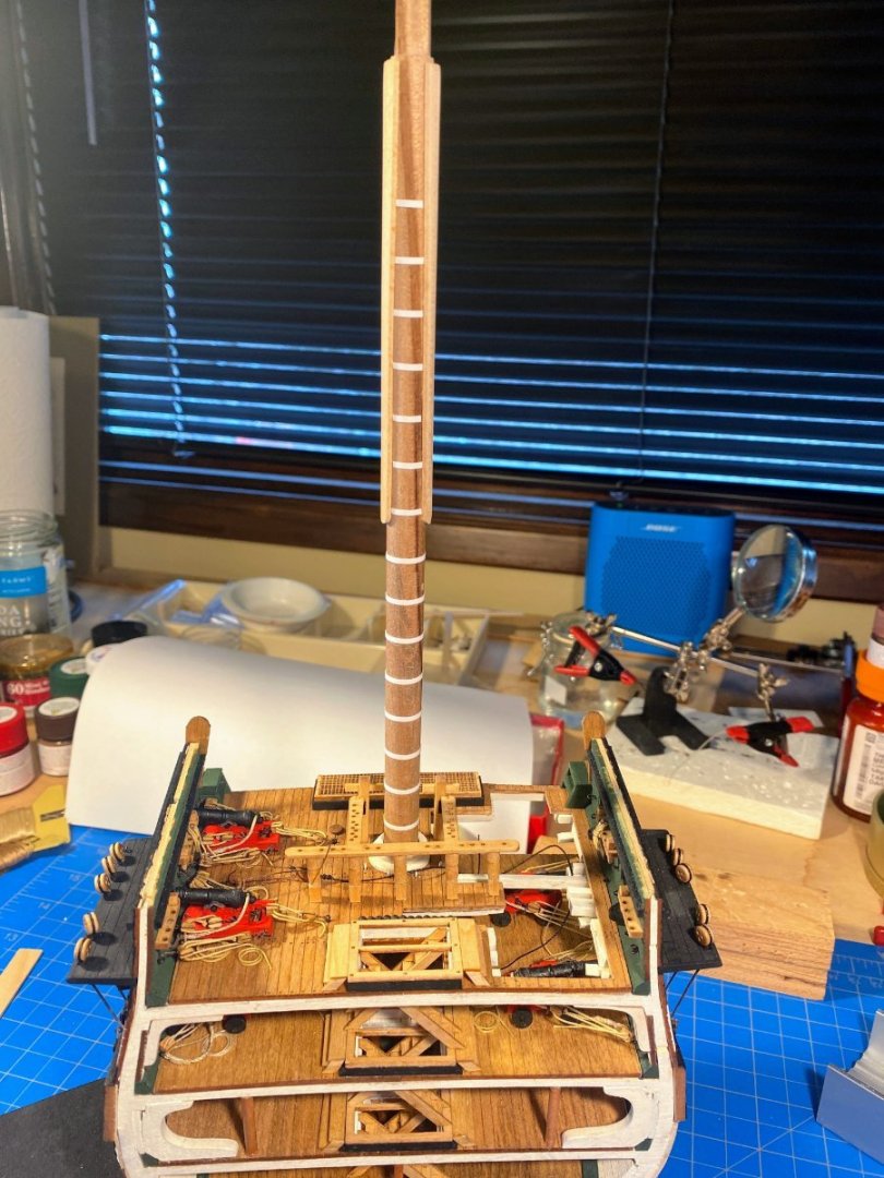
A milestone of sorts . . . I have stepped the mast. I have mentioned previously that I enlarged the mast hole a bit in each deck so that there would be some wiggle room with which to assure that the mast would be vertical crosswise and would have the correct amount of rake. Good thing I did that because the resulting wiggle room was minimal, leaving little “wiggle” with which to make adjustments. As it leaned naturally the mast had too much rake and leaned a bit to starboard. I spent quite a bit of time making the determination that if I pulled the mast as far forward and as far to port as possible, I was comfortable it was truly vertical athwartship and had close to the requisite 3 ½ degrees of mast rake. But making that determination was not simple, because I could not assume that i) the tops of the bulwarks were parallel to each other and to the water line, ii) the painted waterline was truly horizontal, or iii) the top of the work bench is level in all respects. I had a bit of a lightbulb-in-the-brain moment one morning when I walked into my work room, my first cup of coffee in hand. Looking at the model head on from maybe 20 feet away, the mast leaning naturally, I could not remember, and I could not tell, whether it was leaning to port or to starboard. Maybe, just maybe, I had been overthinking things. To eliminate the wiggle and bring the mast forward and to port, I put a drop or two of glue on the bottom of the spar deck mast surround, and positioned it such that the mast was where I wanted it. I let the glue set a little and pulled the mast out (a tighter fit now) and let the glue dry firmly. I then did the same with the berthing and orlop deck surrounds. The gun deck surround was a little more problematic, as it was a very tight fit getting it in place with the guns and pumps and such, and once it was in place, I didn’t feel like pulling it back out to apply some glue. So that surround is not glued in place . . . nor does it need to be. So now I have some mandatory time away from the shipyard, recovering from lower spinal surgery earlier this week. No bending, twisting or prolonged sitting for several weeks I’m told. Not what I wanted to hear, but the good news is I can walk as much as I feel like, and with a pretty minimal amount of pain meds I’m walking just fine. So life is good. 😀


- 163 replies
-
- 5
-
-
- Model Shipways
- Constitution
- (and 2 more)
-
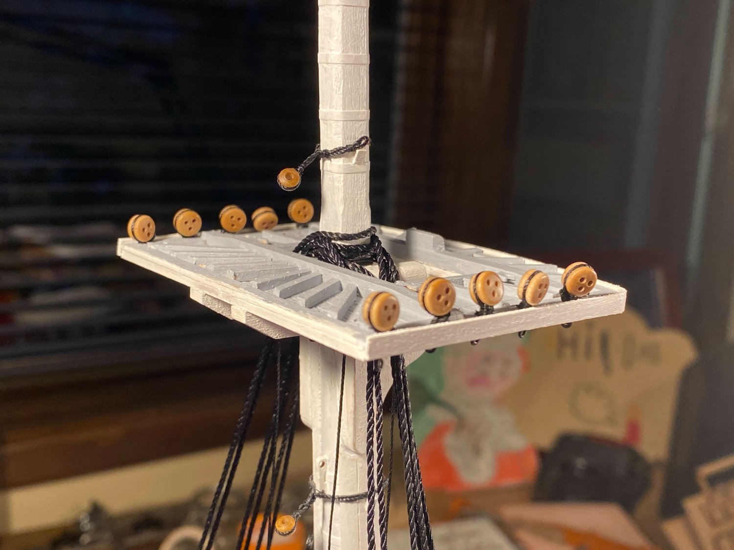
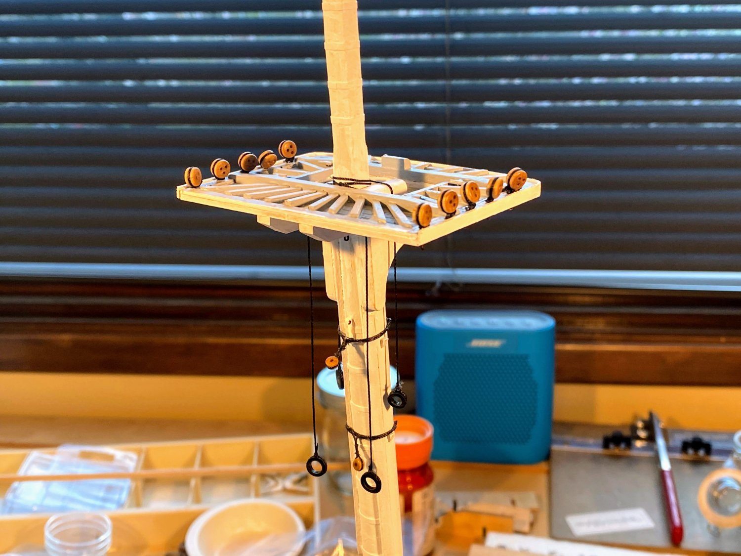
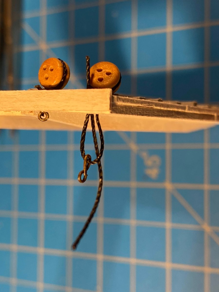
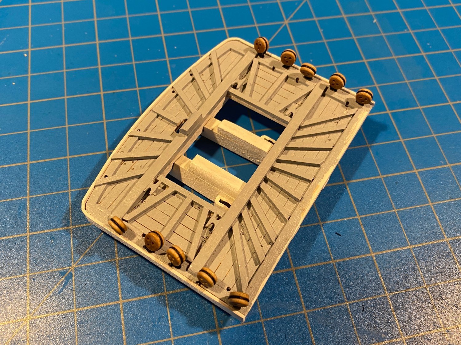
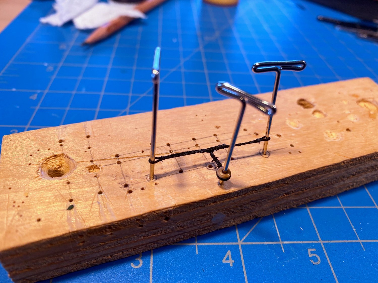
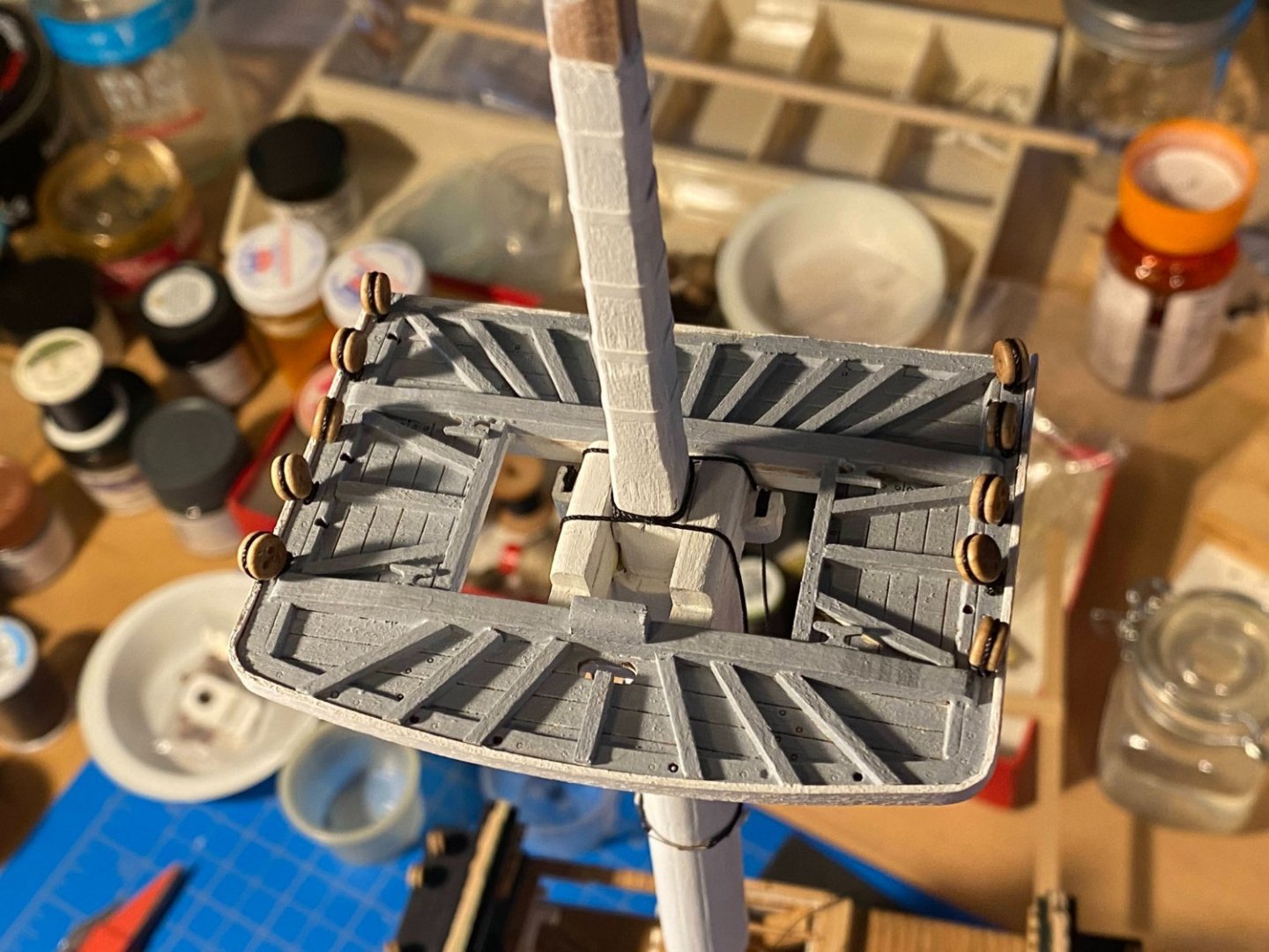
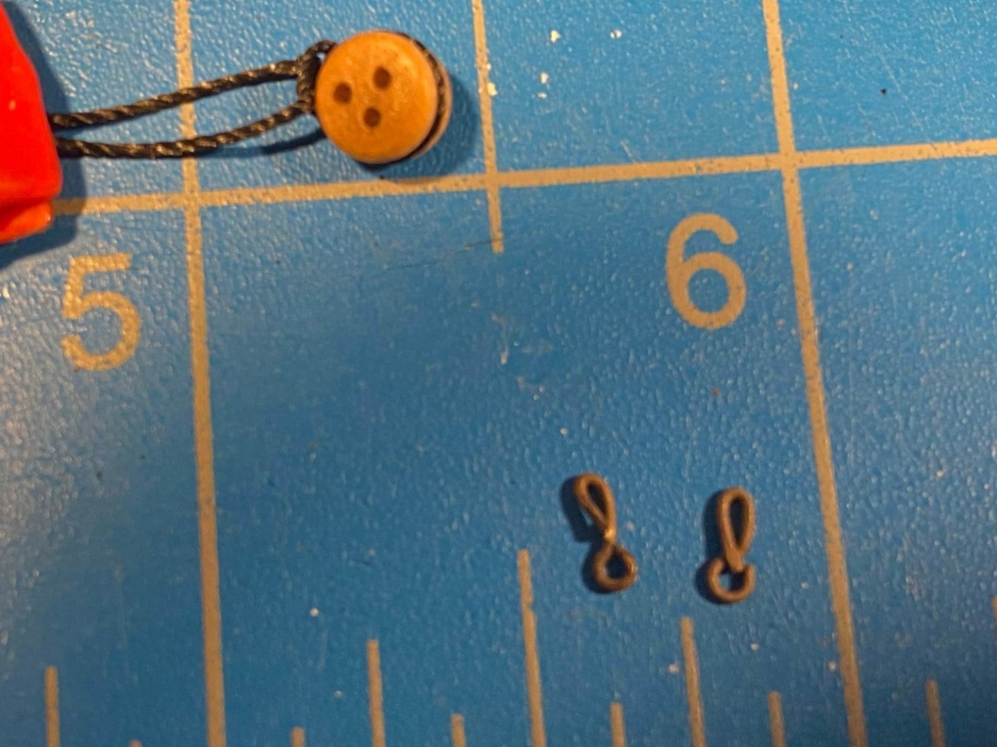
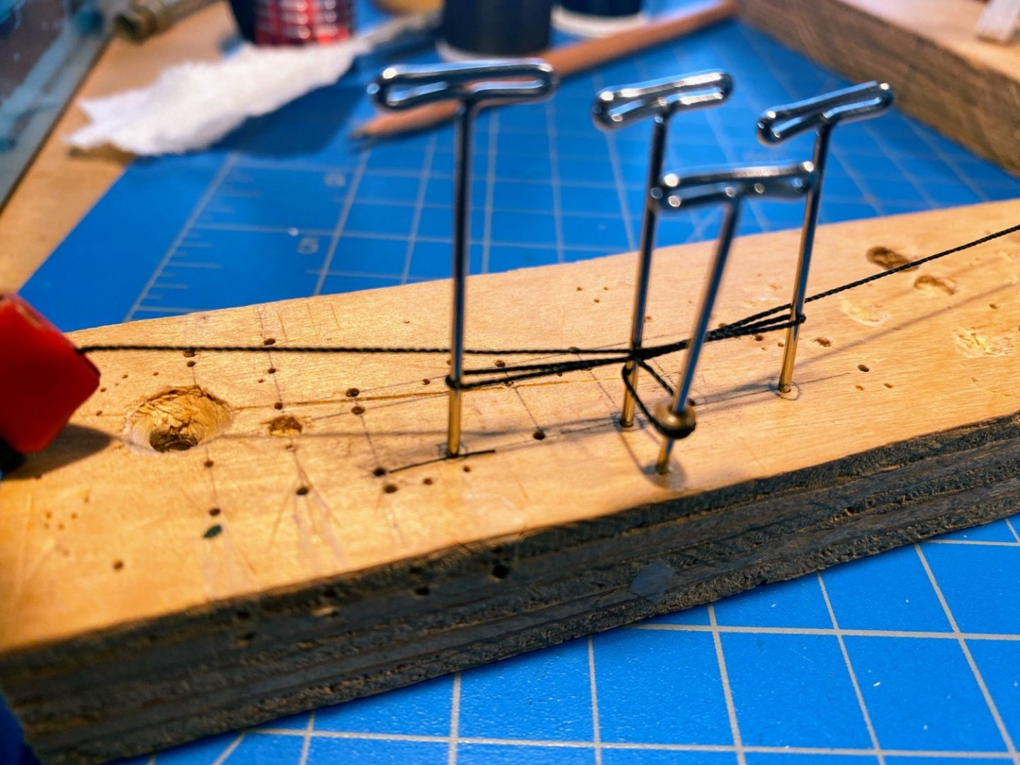
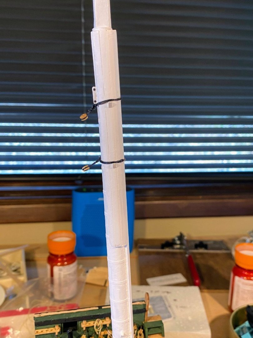
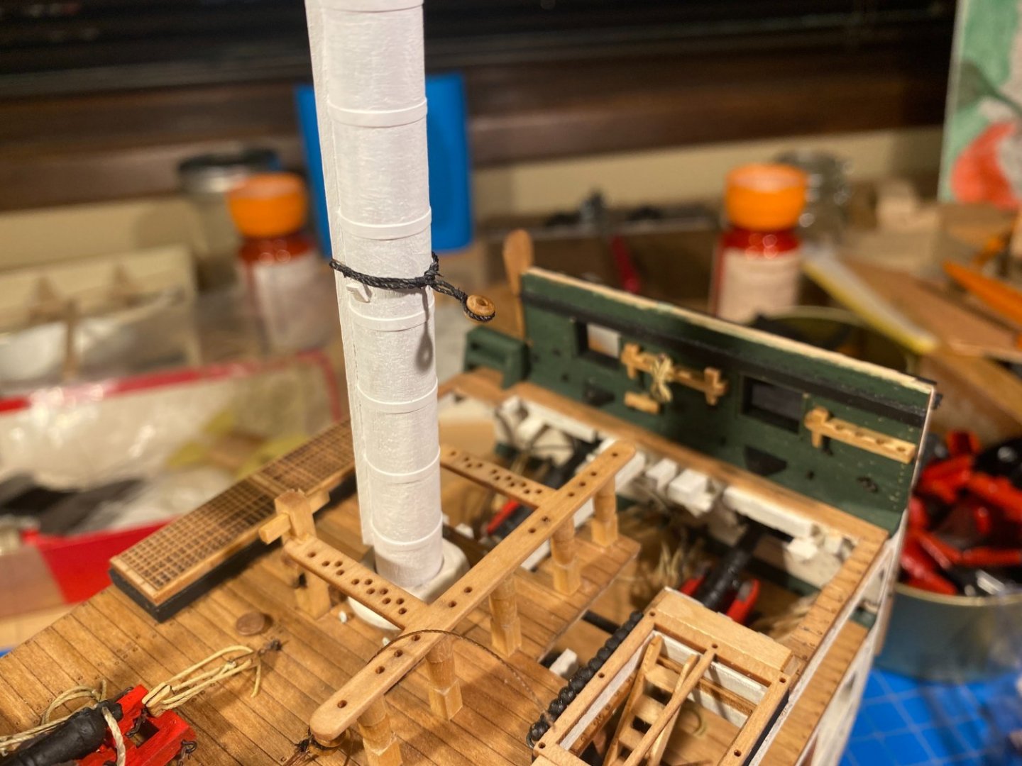
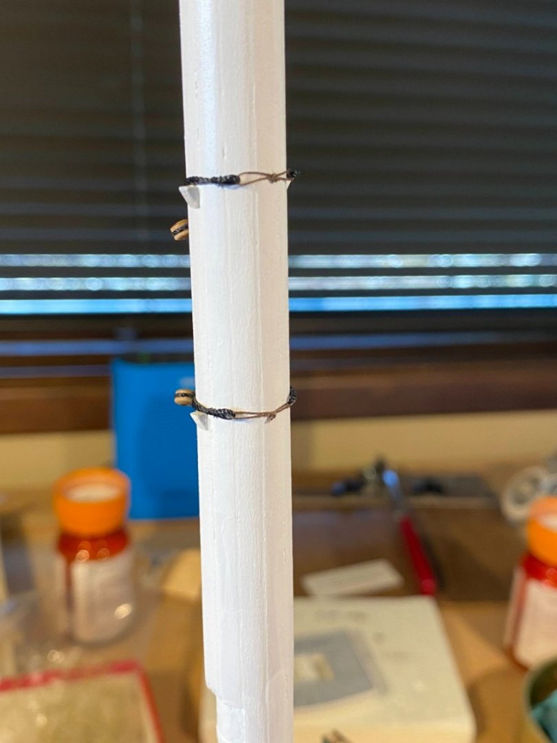
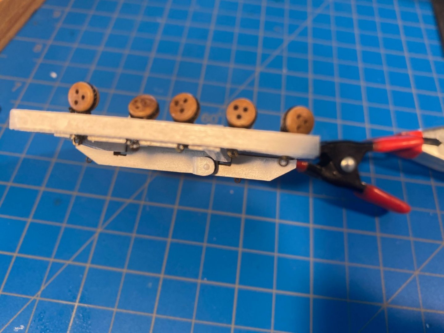
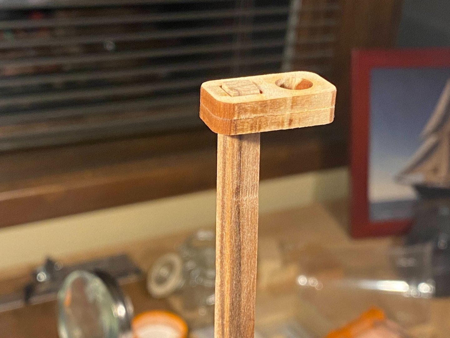
The fighting top has ten precisely laser cut oblong holes, five each port and starboard, for securing the topmast shroud deadeyes along the upper side of the fighting top. Attached to the lower side of each hole is a ring to which the upper end of each futtock shroud will be hooked. The instructions have you use blackened brass wire to wrap around the deadeyes and then pass through the holes to form the ring below. As best as I can tell looking at the real ship, the deadeyes are secured with heavy rope, not with a metal ring, and I prefer working with thread rather than wire. But the ring below is metal, so I had to figure out a way to attach darkened brass eyebolts to the thread tied around the deadeyes. I tried any of a number different approaches that didn’t work. I think I spent as much time getting the first assembly put together as I did working on the other nine total. Here is what finally seemed to work. First I took some .020” thread, wrapped it around the deadeye, and secured it with a square knot. Then I took an eyebolt, cut a very short piece off the end of the stem, and wrapped the remaining stem around to form a loop. I passed the two ends of the thread through the hole in the fighting top, then passed one end through the loop I made in the eyebolt. I then passed that end back up through the hole in the fighting top (having previously hardened that end with a drop of CA glue), then used that end to pull the loop end of the eyebolt up into the hole. I then applied a drop of thin CA glue to the bundle of thread in the hole, thinking diluted white glue might not be strong enough. Then to add a belt to the suspenders, after trimming the loose ends, I stuck a small dab of thick CA glue into the bottom of each hole. It all seems pretty secure. The instructions have you add two eyebolts (also seen in the plans) to each trestle tree, which I did. They also call for six eyebolts to the bottom of the front edge of the fighting top. There are conveniently six pre-drilled holes running along that front edge, but strangely the photos in the instructions clearly show the eyebolts between, not in, those holes. Looking at the plans it does not appear that any of these eyebolts will be used to secure anything, and looking at the real ship, no such eyebolts appear. I chose to leave them off my model. Next up are what the instructions refer to as bobstay collars. The bobstays are standing rigging which runs from the deck up through bullseyes affixed to the aft side of the main mast then on up to the forward side of the mizzen mast. Of course they do not appear at all on this model, since there is no mizzen mast, but the bullseyes they run through do appear. The three sets of chocks attached to the mast earlier support the bullseyes at the appropriate height. The bullseyes are seized onto the collar (.020” thread) which runs part way around each side of the mast, where a loop is seized at each end. The loops are pulled tightly together by a thinner line, or lanyard, that comes around the front end of the mast. More easily understood when looking at the pictures below or those in the instructions. I assembled a jig similar to the one in the instructions, only I used only T-pins rather than a mix of T-pins and brass tubes as the instructions suggest. After wrapping the collar/thread around the pins, I seized a loop at each end, seized on either side of the center pin, and seized the throat at the end opposite the bullseye seizing. Since I am not very adept at seizing, this took quite a bit of time. Don’t tell anyone, but instead of seizing line the old fashioned way as I would have if I were working with a real piece of rope (too difficult to describe here), most of my seizing consists of a row of half hitches. With the very thin fly tying thread I use, you can’t tell the difference. Not mentioned by the instructions, but the portion of the mast where the lower collar is affixed has a smaller diameter than the upper two, since the chafing protector is smaller lower down. The jig had to be adjusted accordingly to get the proper length. There is a fourth bobstay collar that is to be installed later on the upper, square section of the lower mast, but I left that for a later day, as do the instructions. I’ll have to keep in mind, though, that the upper section of mast has an even smaller diameter than the lower one and the jig will need to be adjusted again. Once each assembly was secured with diluted white glue and all the loose ends were cut, I removed it from the jig and made the lanyards. I took some dark brown sewing thread and first threading it through each loop of the collar. I then tied an overhand knot as tightly as I could, then tied the other half of a square knot around the other part of the lanyard. A few drops of diluted white glue and the bobstay collars were secure.


- 163 replies
-
- 2
-
-
- Model Shipways
- Constitution
- (and 2 more)
-
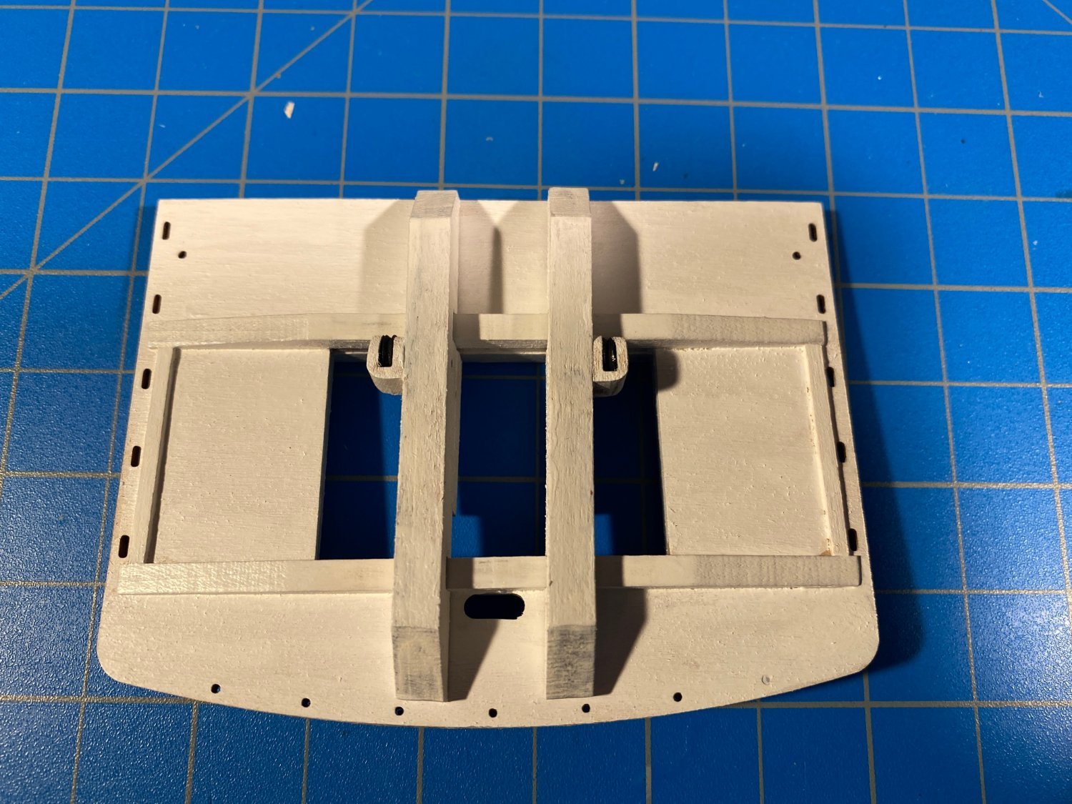
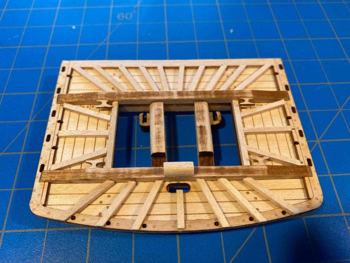
Mr. BlueJacket kindly messaged me to point out that the trestle trees in the last two photos above are backwards; that is, the port one is on the starboard side and vice versa. The sheaves should be outboard, not inboard. Fortunately they are only dry fit in place to be photographed and not glued.
- 163 replies
-
- 1
-
-
- Model Shipways
- Constitution
- (and 2 more)
-
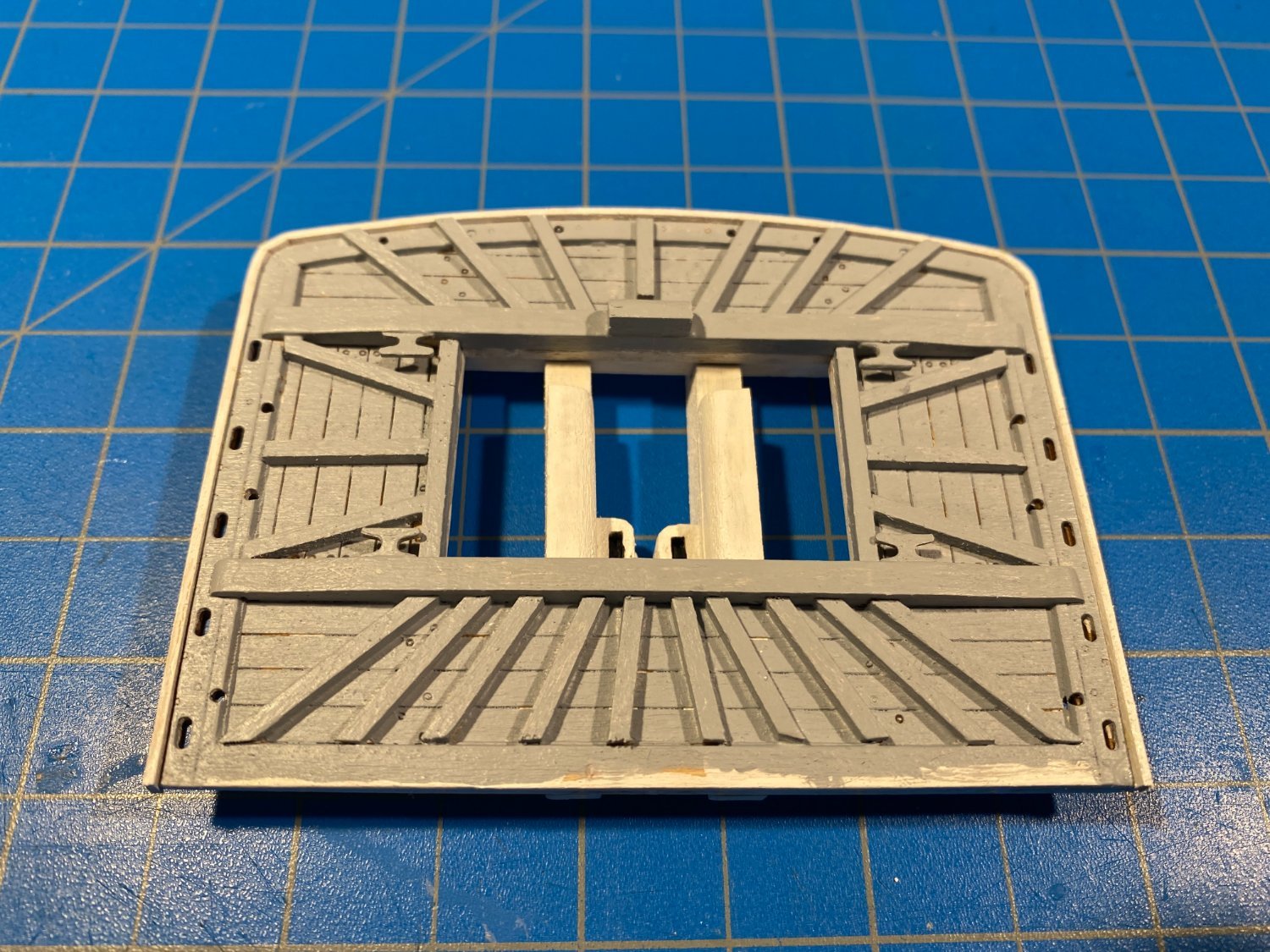
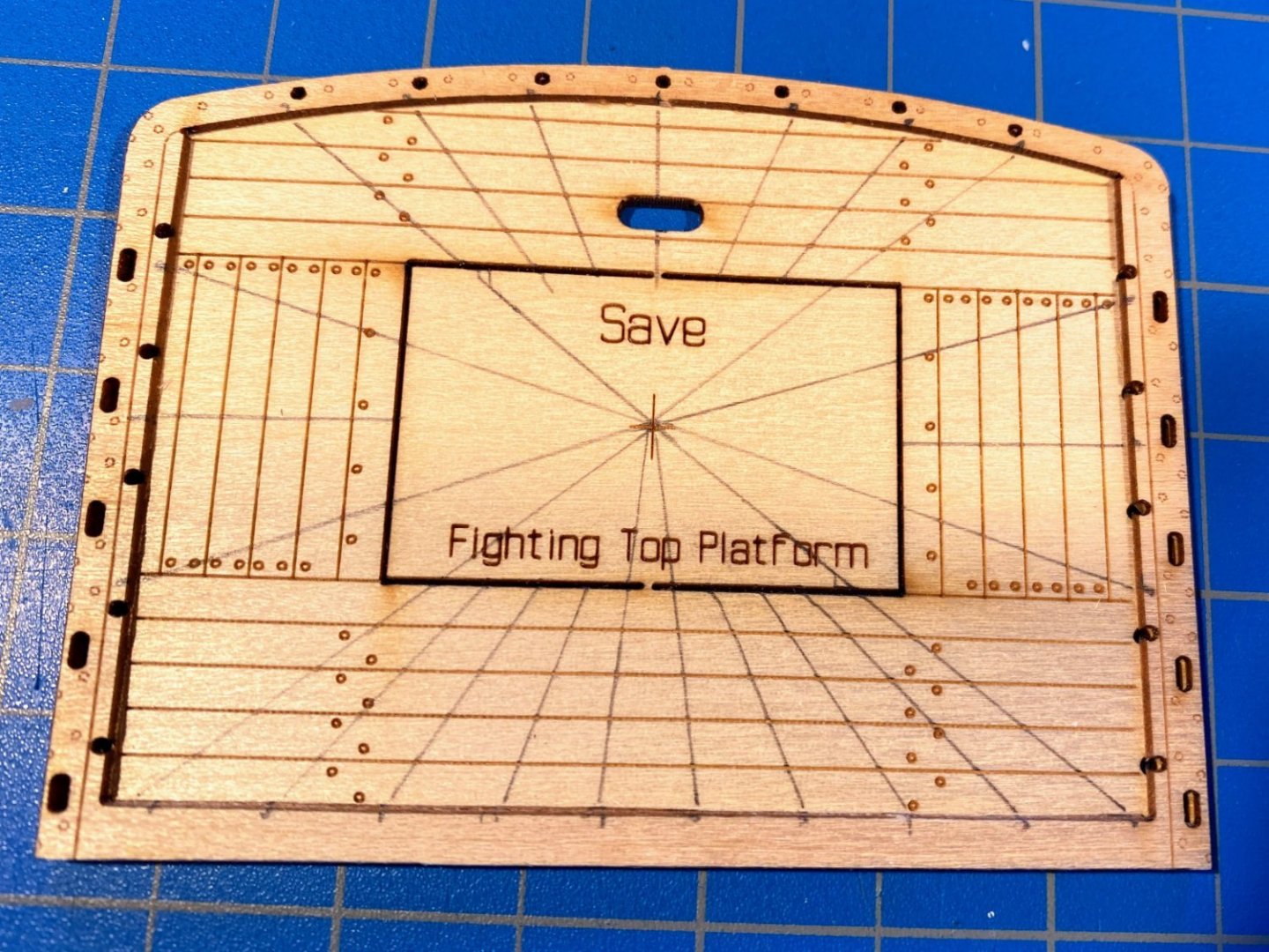
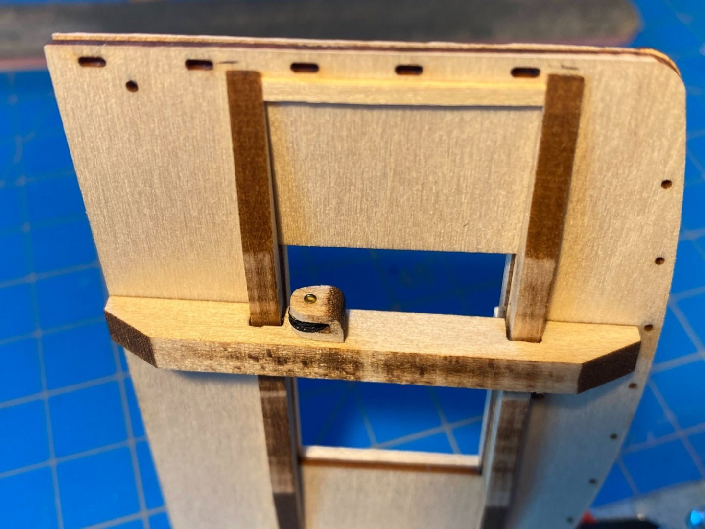
Assembling the fighting top is pretty straightforward. The laser cut floor and a small frame around the perimeter fit together precisely. The center cutout in the floor has a center mark, which greatly facilitates gluing the timbers in place. I drew the various lines running outward from that center mark. The instructions suggest determining the location of the aft timbers directly from the plans rather than using the center mark, but I don’t know why. The timbers overlap the frame forward, and cutting the notches to accommodate them turned out to be easier than I expected. And consistent with expectations, the laser cut upper crosstrees fit precisely. There are also four laser cut cleats which can be seen in the second picture below. After gluing them in place I saw in the instructions quite a few pages ahead that at least a couple of them will be used to secure some lower yard rigging, and I have some concern that they may be too flimsy for the job. A challenge for another day . . . The underside of the fighting top is as straightforward as the top side. The laser cut lower crosstrees and trestle trees fit precisely as expected. Same with what are referred to as the “thumb cleats” and their cast metal sheaves. I painted the sheaves black, I guess out of a tendency to leave no metal piece untreated, but so painted they become almost invisible. The instructions have you glue one trestle tree in place (3/16” off the center line) and leave the other one unglued, presumably to allow for a tight fit when it's time to glue the fighting top to the mast. I preferred to leave both trestle trees unglued. Next I painted the whole thing white, then mixed up some light gray to paint the upper side of the deck. Finally I painted white half (horizontally) a 1/8 x 1/32 strip, and after soaking it, and with the help of an old iron, carefully wrapped and glued it around the front and sides of the fighting top. A few eyebolts and some deadeyes will finish this stage of the fighting top. The instructions have you build and install the guard rail much later in the build. Note added two months later -- part of a caption to a photo on page 56 of the instructions says "18 eyebolts added to various locations." Those eyebolts are not mentioned in the instruction text, and I completely overlooked that photo caption. Ten of those eyebolts are supposed to be added to the top of the fighting top, just inboard of where the deadeyes will be installed, and those ten eyebolts will eventually anchor the royal and topgallant shrouds. Easier to add them at this point in the build than where I am now (with deadeyes in and fighting top installed on the mast), but fortunately I have not yet installed the topsail shrouds, which would have made the job almost impossible.


- 163 replies
-
- 6
-
-
- Model Shipways
- Constitution
- (and 2 more)
-
I continue to be in awe of your kit bashing. It took me weeks to get up the courage to remove one side of the spar deck planking and frames to make the cannons below visible. At the rate you're going you'll pass me in the not too distant future, and I'll have the benefit of following behind your build log. I look forward to that.
- 27 replies
-
- 1
-
-
- Constitution
- Model Shipways
- (and 1 more)
-
Phil, I am delighted to see another Connie Cross build log. You have obviously done a lot more historical research, and have been more willing to add to and vary from the kit, than I have. That is fun to see. I will be following your log closely. One comment on the instructions. They are generally very good and certainly quite detailed, but sometimes they have errors so it is important to also take a look at the plans nearby when reading them. You have probably noticed that. I look forward to watching your build.
- 27 replies
-
- 1
-
-
- Constitution
- Model Shipways
- (and 1 more)
-
Well do I feel stupid (not the first time). I wrote and posted that last entry while away from my model desk for a couple of days, and now upon re-examining the plans and instructions on my return, I see that the “mistakes” I said I made were not mistakes at all. I don’t know how I got that idea into my head! Two weeks prior I had tested positive for Covid, with very minor symptoms, and maybe I did not recognize the Covid fog. In any event, the plans, and at least one of the instructions’ photos, do show a gap between the bottom of the chafing protector (makes more sense to me than “fish”) and the mast surround, and the chafing protector does in fact wrap around the front of the mast and not the back. I edited my post accordingly.
-
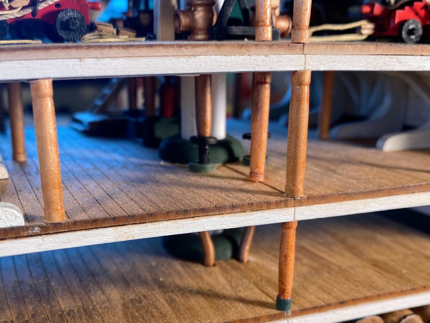
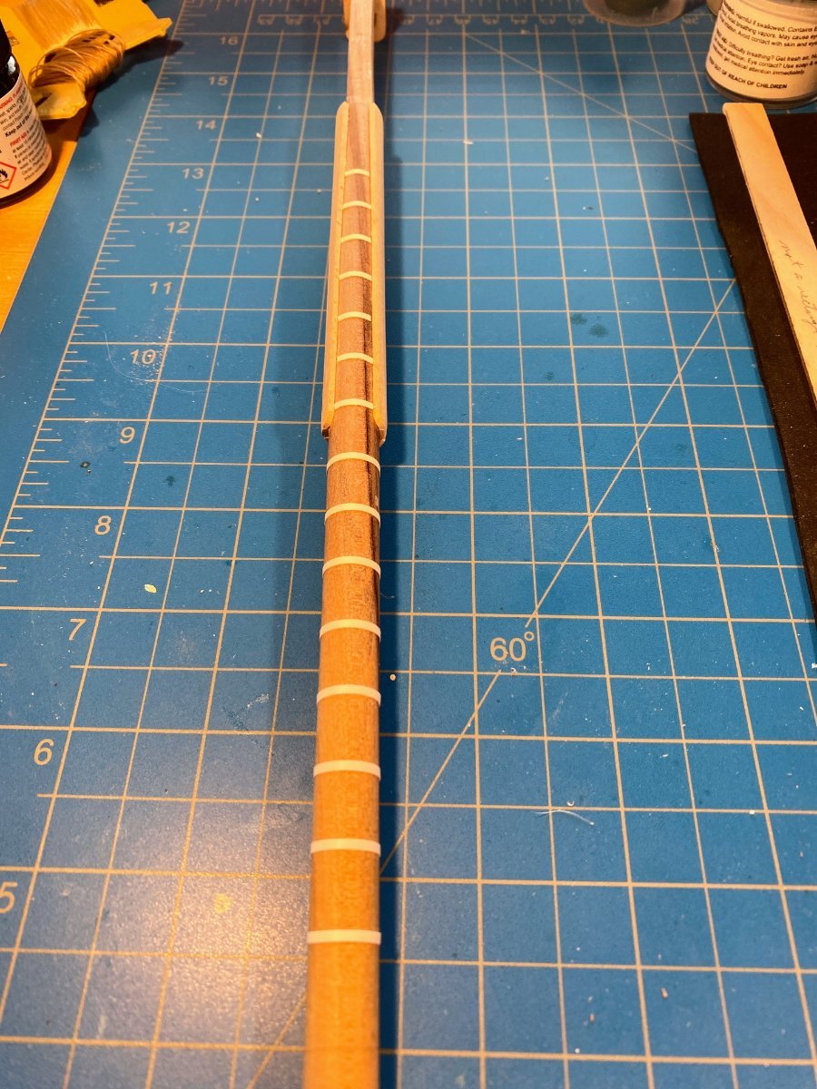
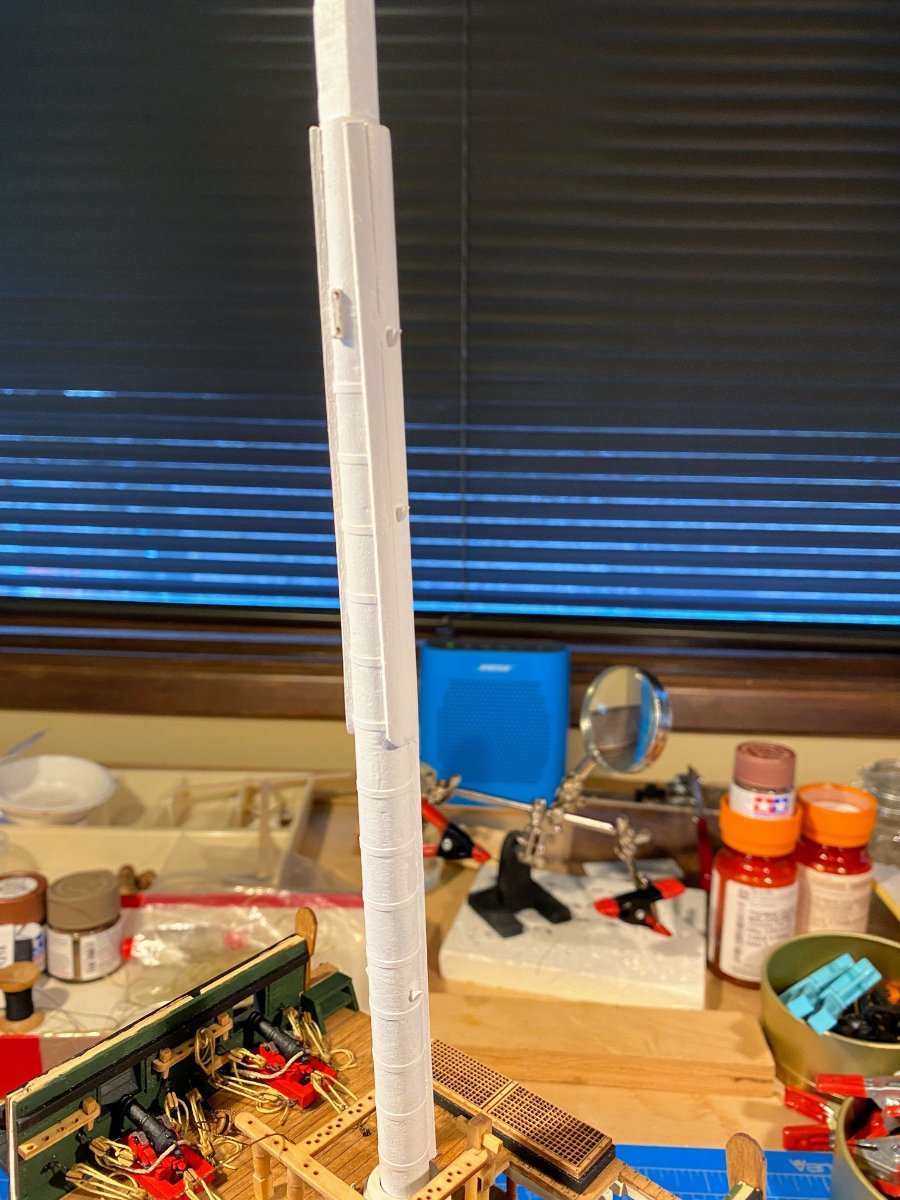
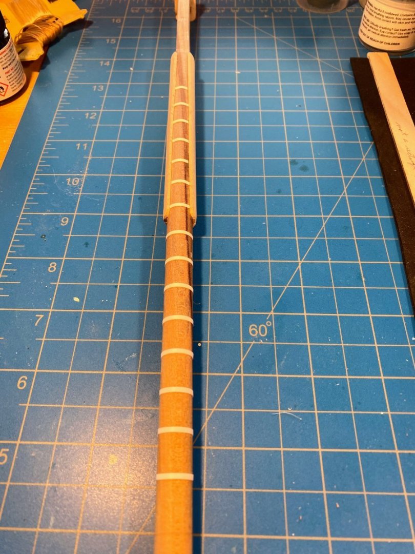
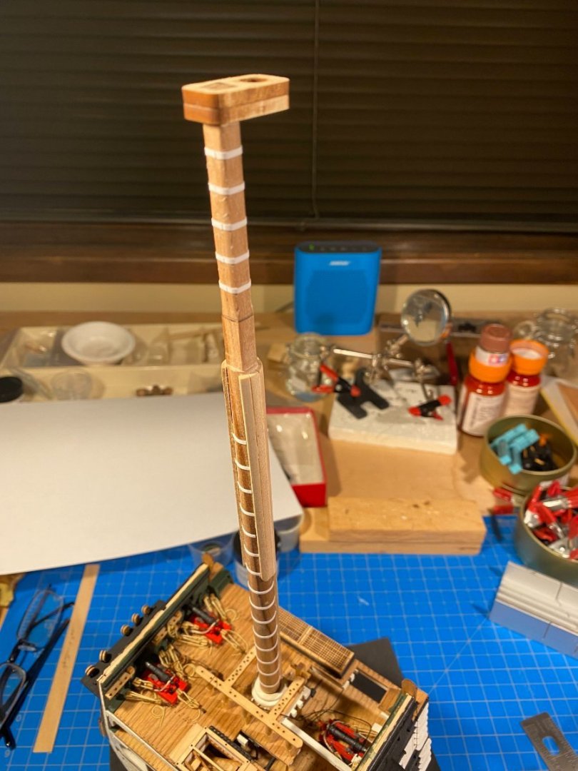
From the square cut section down to the deck, the aft portion of the mast has wrapped around it what the instructions refer to as a “chafing fish”, a term I have never heard before and can’t find in any online nautical dictionary. In any event, it consists of additional planking, presumably to absorb chafing from running rigging. On the model, it is made from nine 1/16” x 1/8” strips, the middle three of which are to be cut to a length of 8-7/8” and the outer three on each side to 4-5/16”. The middle three cut to that length run all the way from the square portion of the mast down to the deck, which won’t work since it leaves no room for the spar deck mast surround. I cut them shorter allowing for the mast surround and an additional ⅛” gap between the chafing fish and the surround. As instructed, I beveled the edges of each strip so that each one meets flush with the adjoining one, but I apparently did not bevel them sufficiently, as there were some small gaps at the surface.. The gaps were easily remedied with some wood filler, but the “fish” ends up wrapping a little farther around the mast than shown on the plans. I found myself thinking I should have used 1/16” x 3/32” instead of 1/16” x 1/8” strips, but better to have done a better job of bevelling the adjoining edges of each strip. The instructions have you install the lower mast cheeks at this time, carefully sanding/grinding away portions of the chafing fish so that the cheeks can be tangent with the surface of the mast itself. Since the cheeks help support the fighting top and should therefore be glued to its underside without any gap or misalignment, I decided to delay this until the fighting top is assembled and ready to be installed. That project will be made a little more challenging by the fact that the fighting top will be horizontal, parallel with the water line, and not perpendicular to the mast, given the latter’s rake (at least I assume that’s correct, and that appears to be the case on the plans). Next up . . . mast bands, which wrap between the edges of the chafing fish and all the way around the mast where it is squared for a few inches at the top. The kit supplies 1/64 x 1/16 brass for this purpose. While thinking about how best to put a waterline on my previous build (Joshua Slocumb’s Spray), I learned on these forums about a product called Chartpak, which is vinyl tape in a variety of widths and colors. In addition to a roll of black I purchased for the waterline, I purchased a roll of 1/16” wide white to make a mast band for that model. Voila! It worked like a charm on Connie’s main mast. It cuts easily with scissors and it is easy to trim if the first cut is a little long. And it wraps around the mast perfectly conforming to the curve with virtually no effort or tools, certainly without anything like needle nose pliers or wire cutters. It’s only shortcoming is that the adhesive on the back of the tape doesn’t adhere to anything for very long, so I had to add a little bit of glue. I completed all the bands in no time, and the end result looks pretty good. After adding laser cut chocks and a fairlead, I gave the whole thing a couple of coats of white paint (without any special priming of the mast bands needed!). I have to say I’m pretty pleased with the result.

- 163 replies
-
- 3
-
-
- Model Shipways
- Constitution
- (and 2 more)
-
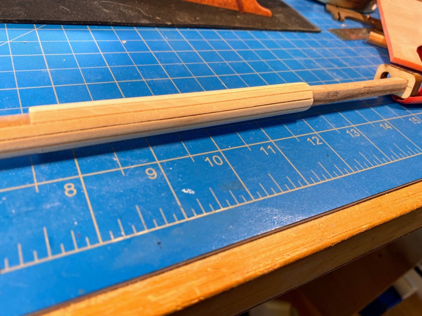
After a little travel and some other head-clearing distractions I’m ready to tackle the mast. The initial part of the mast work doesn't lend itself to meaningful photography, so this post will be a lot of text and only a couple of photos. For the lower mast the kit supplies a 16” x 7/16” dowel (identified by those dimensions in the parts list). The first thing we’re to do with that dowel, according to the instructions, is “cut [it] to the length of 16-3/8” long.” If anyone knows how to cut a 16” dowel to 16-3/8” please let me know; knowing how to do so would save a lot of time wasted measuring twice. 😀 Fortunately most of the missing ⅜” the instructions think you can produce consists of a knob at that bottom designed to fit into the mast foot created (in my case) close to a year ago. Again in my case, that knob is unnecessary to secure the mast, as I will use the mast surrounds to securely hold the mast vertical crosswise and with the desired amount of rake. And once all the barrels are in place down there, the interface between the mast bottom and the mast step won't be visible. Speaking of mast rake . . . I enlarged each of the deck mast holes as I went along to allow for some final adjustment before securing the surrounds, but I think I need to pull the mast just a little bit farther forward than the holes allow to avoid too much rake. The instructions suggest tapering the below decks part of the mast, which I did, but I tapered only the aft half so the above decks part can be brought farther forward. The plans show a mast rake of 3 ½ degrees relative to the waterline, and I think that’s about what I get if I pull the mast forward as far as it goes. I'll try precision before gluing anything in place. The mast above the deck also is tapered to 3/8”. For that, I first tried using a small plane, but I found it difficult to control, and make somewhat consistent, the amount I shaved off. Trying a different approach, I wrapped some tape around the lower end of the dowel and was able (barely) to wedge it into the chuck of my drill. With a sanding pad and the drill running at a fairly high speed I was able to get much better results. The top 3-1/8th” is cut square. For that I pulled out a Dremel beveling table I bought years ago and rarely used since because its grip on the Dremel drill was too flimsy. I confirmed that it hasn’t gotten any stiffer over the years, and the flattened sides that resulted were not as flat as they needed to be, but for the most part the flaws disappeared with some sanding. A 1/16th chamfer is then cut into each corner. . . I used a sanding block for that. Finally, the top 1/4” is cut to a square tenon, to accept the mast cap (which is made from two identical 1/8” thick laser cut pieces). Here, I made a mistake, as the plans appeared to show the mast extending about a 1/16” above the cap, as I would expect, rather than having it end flush with the upper surface of the cap. So I cut the tenon to a length of 5/16”. Turns out the mast does end flush with the upper surface of the cap, and what appeared to be an extension of the mast above it is actually two 1/16” square, so-called “spacers” , shown 15 pages later in the instructions. Fortunately a minor mistake.
- 163 replies
-
- 2
-
-
- Model Shipways
- Constitution
- (and 2 more)
-
Many thanks Jon for all the pictures and information; thanks to you too Nic. Hard to believe I started this hobby before we had this wonderful community of generous builders.
-
Thank you Tom. That photo will be a big help. I have occassionally been looking at these forums while taking some time away from the build, and I'm surprised I didn't see your post from a month ago, thus the delayed response. Another question for you or anyone else. . . The instructions refer to four heavy lines (your picture shows 2 of them) which end in thimbles, which are attached to nothing. They just hang there. The instructions refer to them as pendants. Any idea what they are or why they are there? I'm inclined to leave them off my model for fear it will look like I failed to complete something. Just getting started on the mast. I imagine I'll be posting on progress in a week or so.
- 163 replies
-
- 1
-
-
- Model Shipways
- Constitution
- (and 2 more)
-
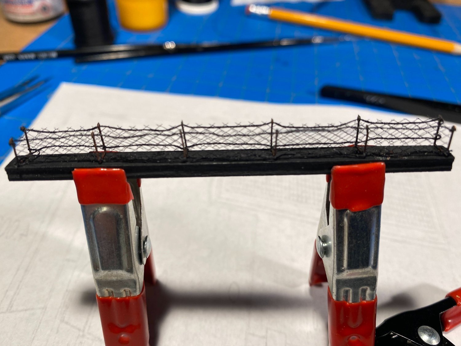
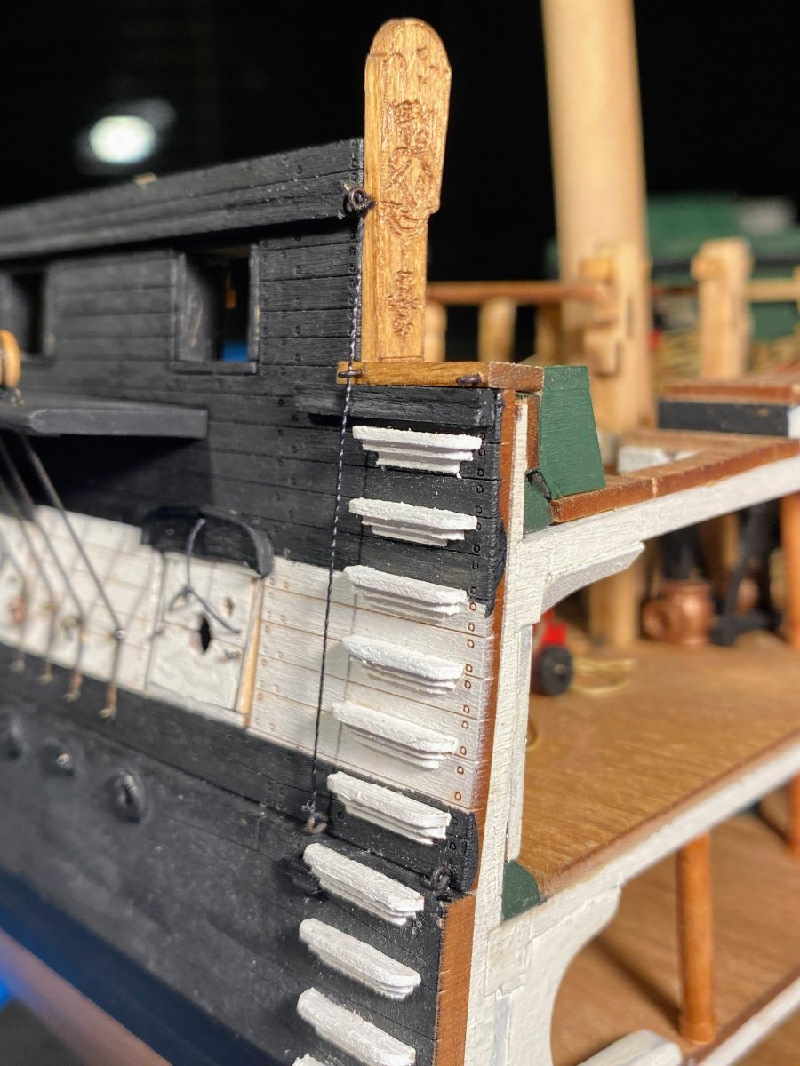
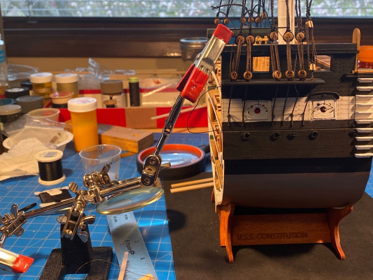
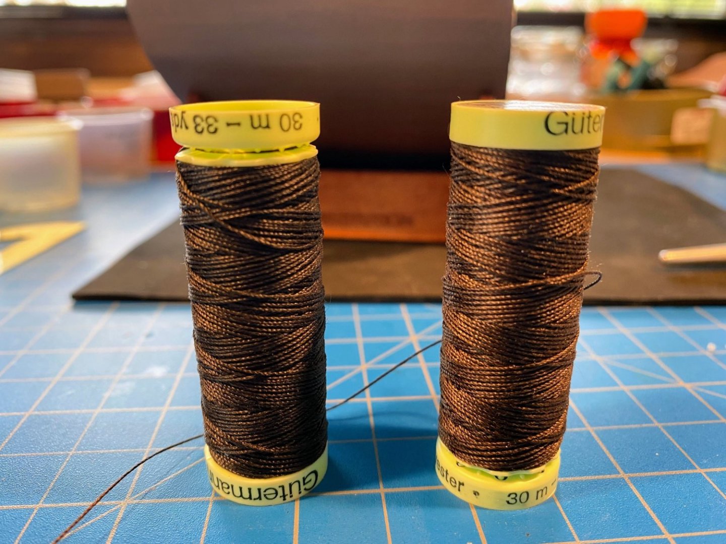
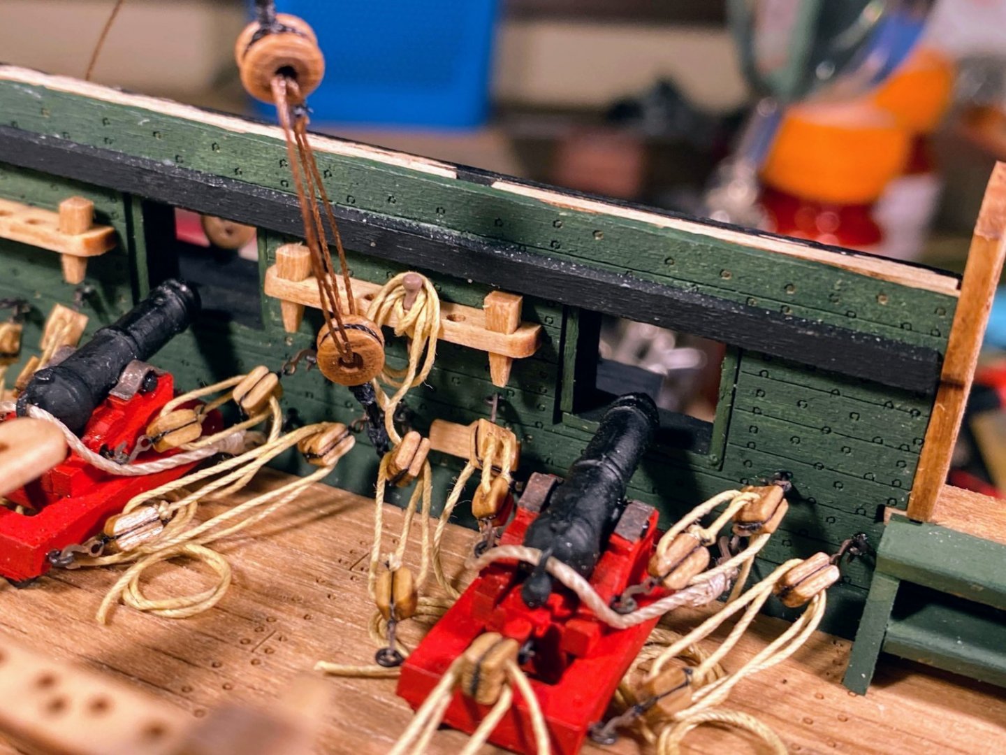
Well I think I can now declare the hull FINISHED! With a couple of caveats. First, as mentioned in a previous post, I’m doing the tedious job of securing the netting for the hammock rails in stages, and I am not gluing them in place on the bulwarks until the end of the build. Similarly I’m also leaving one gangway headboard on each side for the end of the build, since it needs to be glued on end with nothing to support it, and I don’t want to snag them either while rigging the mast. I did manage to finish the other side of the hammock netting, so I am halfway through that job. Hard to see in the photo, but I think I did a better job this time cutting the netting so as not to leave ends sticking up in mid air. One gangway headboard on each side is glued to the end of the bulwark. That was easy. Also easy . . . a few eyebots and thread, and I had a handrail to go with the sea steps previously installed. In the photo you can see where the other headboard is to be installed and how fragile an installation that will be. I’ll probably pin it to make it a little more secure. In the picture below you can also see the trim I molded and glued in place. The mold shaping tool I mentioned previously worked very well, and was easier to use than last time because the American dimensioned trim pieces were very close to a metric dimension used by the tool. One more incomplete project . . . in the process of turning everything upside down and planking the hull I managed to dislodge a few of the teeth in Connie’s grin (ie some barrels). I haven’t gotten around to gluing them back in yet, and I will probably wait until I have installed the mast, so I can look inside and see where its bottom meets the mast step. Finally, I realized that the bentinck shrouds will one day be secured to eyebolts installed months ago in the middle of the spar deck waterways. Installed before the cannons were tied in place and became all but completely hidden from view. Obviously hooking the shrouds to those eyebolts isn’t going to get any easier, so I better do it now. The shroud is seized to a bullseye, which is lashed (with a lanyard) to another bullseye which is seized to a hook. Sounds easy enough, but I discovered that my seizing skills are a bit rusty (“skill” being not necessarily the right word in my case), and there was more than one do over along the way but I eventually got it done. I left the lanyard untied, since I assume that is what I will adjust someday to get the shroud appropriately taut. Hooking the shroud assembly to the eyebolt was not as difficult as I feared; got it done on about the third or fourth try. But once I took a look at how it will eventually look I decided was not happy with the running rigging thread I had used for the lanyard . . . too thick and seemed too light in color. I mentioned previously that I have been taking a few looks at UsedToSail’s build log of the full ship Constitution, and in it there is a interesting discussion about the lanyards used with deadeyes and bullseyes. They are basically part of the standing rigging, but they are intended to be adjusted occasionally, certainly not frequently. Adjustable standing rigging. On the current ship, the deadeyes, the bullseyes and the lanyards are all black, but as mentioned previously I subconsciously decided to leave my deadeyes natural (dark brown). Someone in that discussion suggested making the lanyards dark brown and mentioned having used dark stain to color lighter thread for that purpose. Not having any dark brown thread, I decided to give that a try . . . another do over. I found some thread of a more acceptable thickness, but after staining it’s a little shiny, which I don’t like (not as bad though as in the pictures below). So in my mind the jury is still out on what thread I will use for lanyards (maybe just black). I may make a trip to a fabric store one day to find some thread that is manufactured in a color I like. In any event, I think yet another do over is called for. At least I’m finding hooking it to the eyebolt to be easier than I feared. Finally I decided to coil the end of one of the cannon tackles and hang it from the nearby pinrail. And just for fun I hung another coil on the opposite side, where there are no cannons. So on to the mast, which looks like quite a project. I have decided to take a bit of a break before moving on, probably a few weeks worth, as I spend some time on other things that need to be done and study ahead in the instructions to familiarize myself with the upcoming build. One thing that has me perplexed already is how the other end of the bentinck shrouds are secured to the futtock shrouds . . . . I'm having difficulty understanding the written instructions and something about the pictures just doesn't look right.


- 163 replies
-
- 6
-
-
- Model Shipways
- Constitution
- (and 2 more)
-
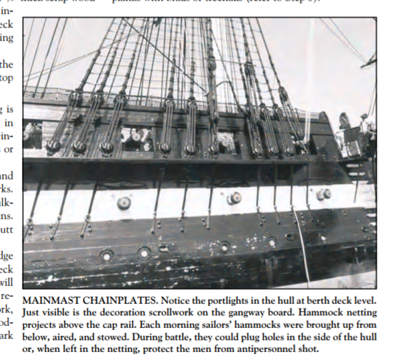
More on whether the chainplates should be perpendicular or run with the shouds to which they are attached . . . One thing I like about Model Shipways is you can download instructions to any of their kits free of charge. Some time ago I downloaded the instructions to their full-ship Constitution, and I refer to it from time to time when the cross-section instructions leave me with a question or two. I was doing that earlier today with a different question in mind and stumbled upon this old picture of the real ship. Apparently the chainplates were not always perpendicular but did at one time follow the line of the shrouds. In restoring/rebuilding an historic ship to turn it into a museum, that strikes me as an odd thing to change. Anyone have any insight on that?
- 163 replies
-
- 2
-
-
- Model Shipways
- Constitution
- (and 2 more)
-
Back to Tom . . . I too used to sail, including a Hobie 16, and occassionally I still get the opportunity (most recently a friend's Hobie 16 on Lake Couer d'Alene). I lived in Hawaii for 18 years as a young adult, and after crewing for others on ocean racers for several years, I raced a Fireball for a while, and then got into Hobie Cats, mostly 16s and then 18s. The 18 was my favorite. . . the dagger boards helped with tacking and the roller furling jib was a plus. As much as I enjoy the moutains and lakes of the Inland Northwest, I miss those days.
- 163 replies
-
- 1
-
-
- Model Shipways
- Constitution
- (and 2 more)
-
Different subject as I finish up some details on the hull and look ahead to the mast and rigging . . . The instructions have you finish the shrouds and ratlines before doing any of the running rigging. The running rigging seems to all tie off to the fife rail and a couple of the rails on the inside of the bulwarks. But doing the rigging from the outside in like that, isn't the standing rigging going to get in the way when trying to tie off the running rigging? Wouldn't it be easier to do the running rigging first? Any thoughts??