HOLIDAY DONATION DRIVE - SUPPORT MSW - DO YOUR PART TO KEEP THIS GREAT FORUM GOING! (89 donations so far out of 49,000 members - C'mon guys!)
×


Tomculb
-
Posts
345 -
Joined
-
Last visited
Content Type
Profiles
Forums
Gallery
Events
Everything posted by Tomculb
-
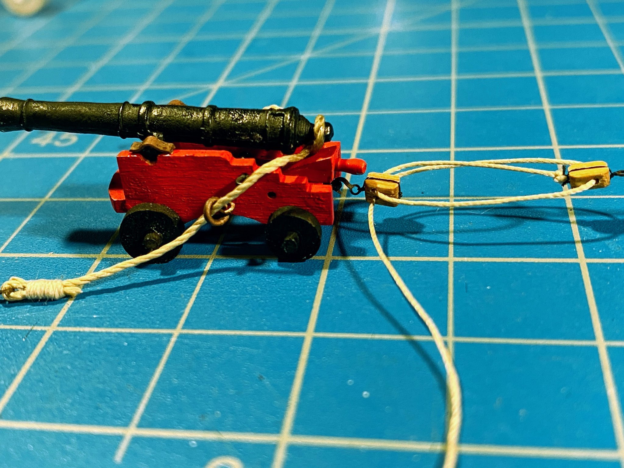
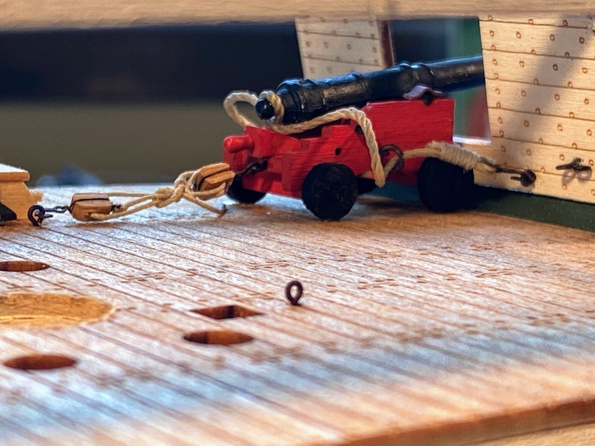
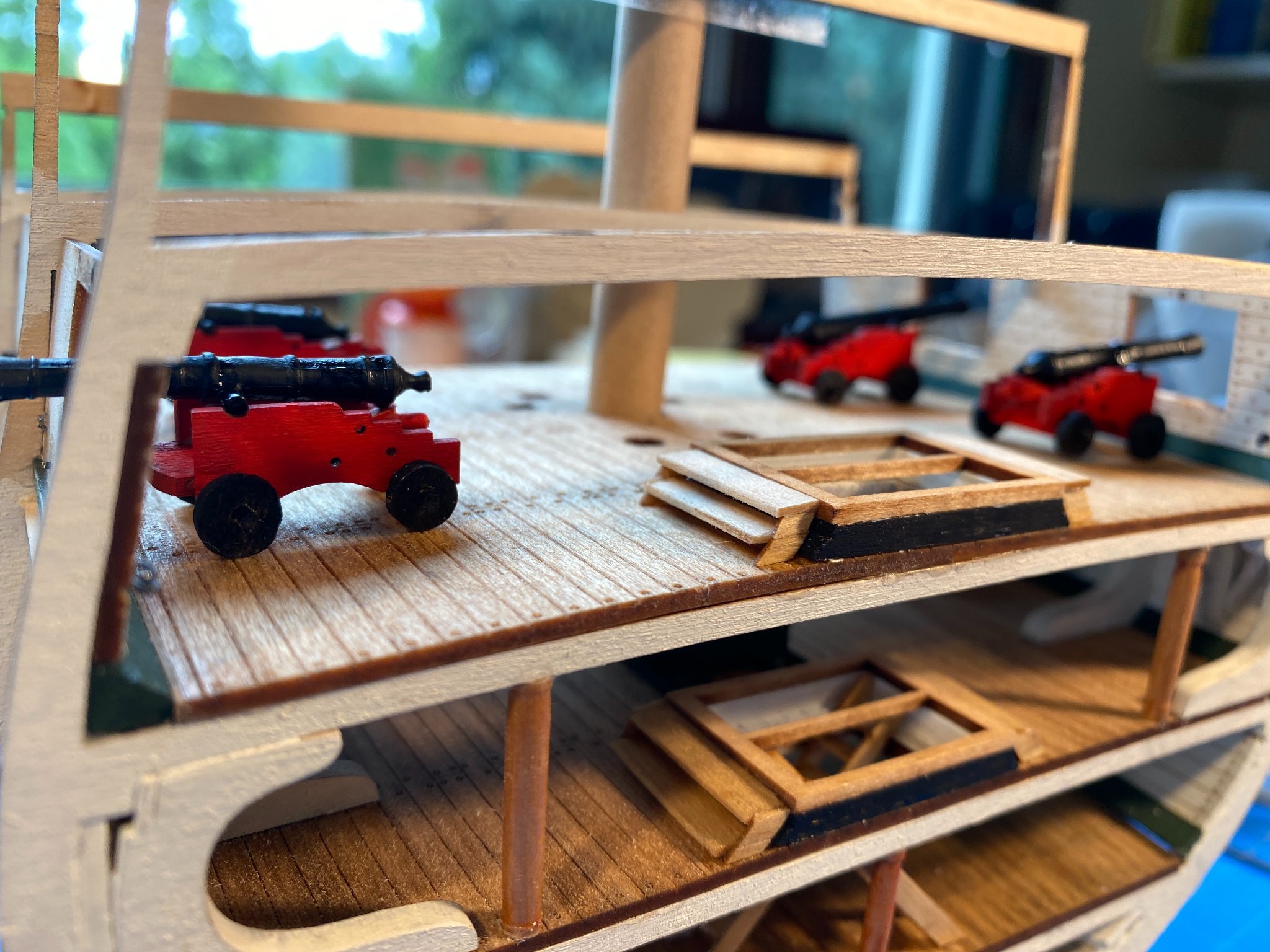
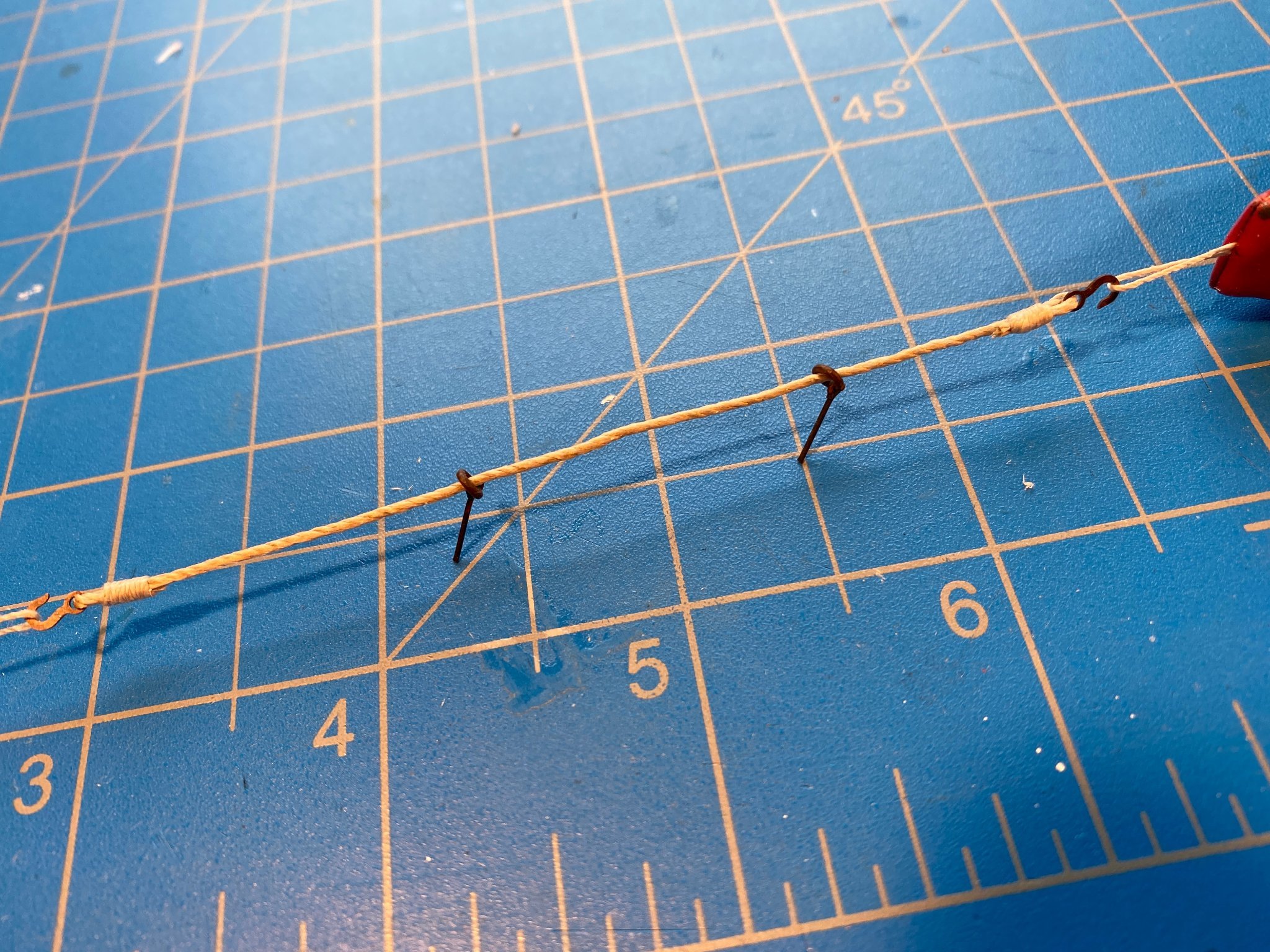
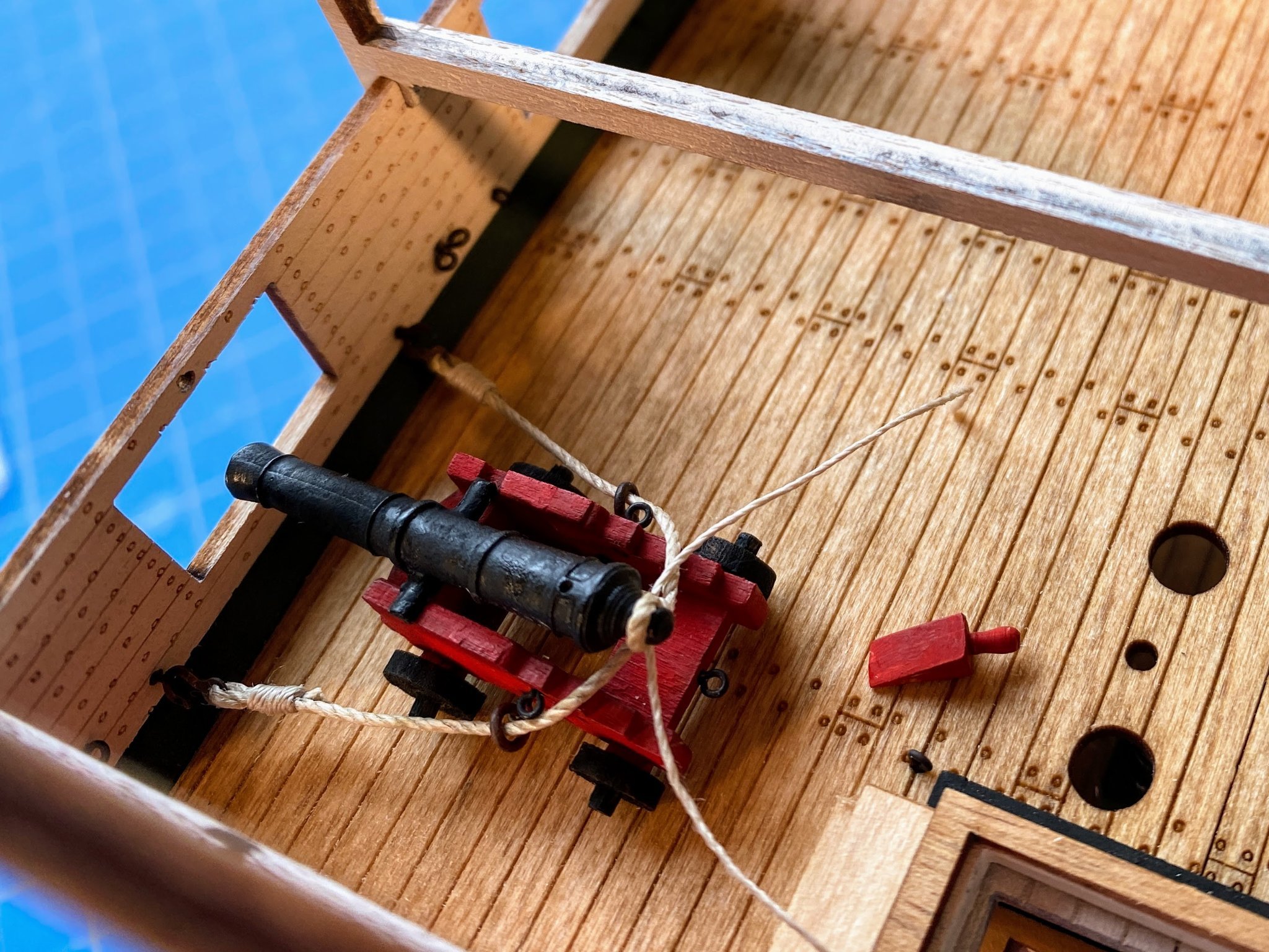
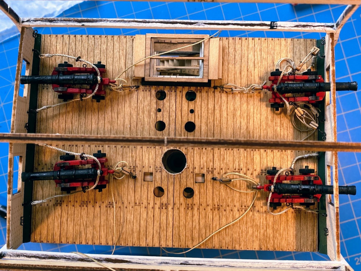
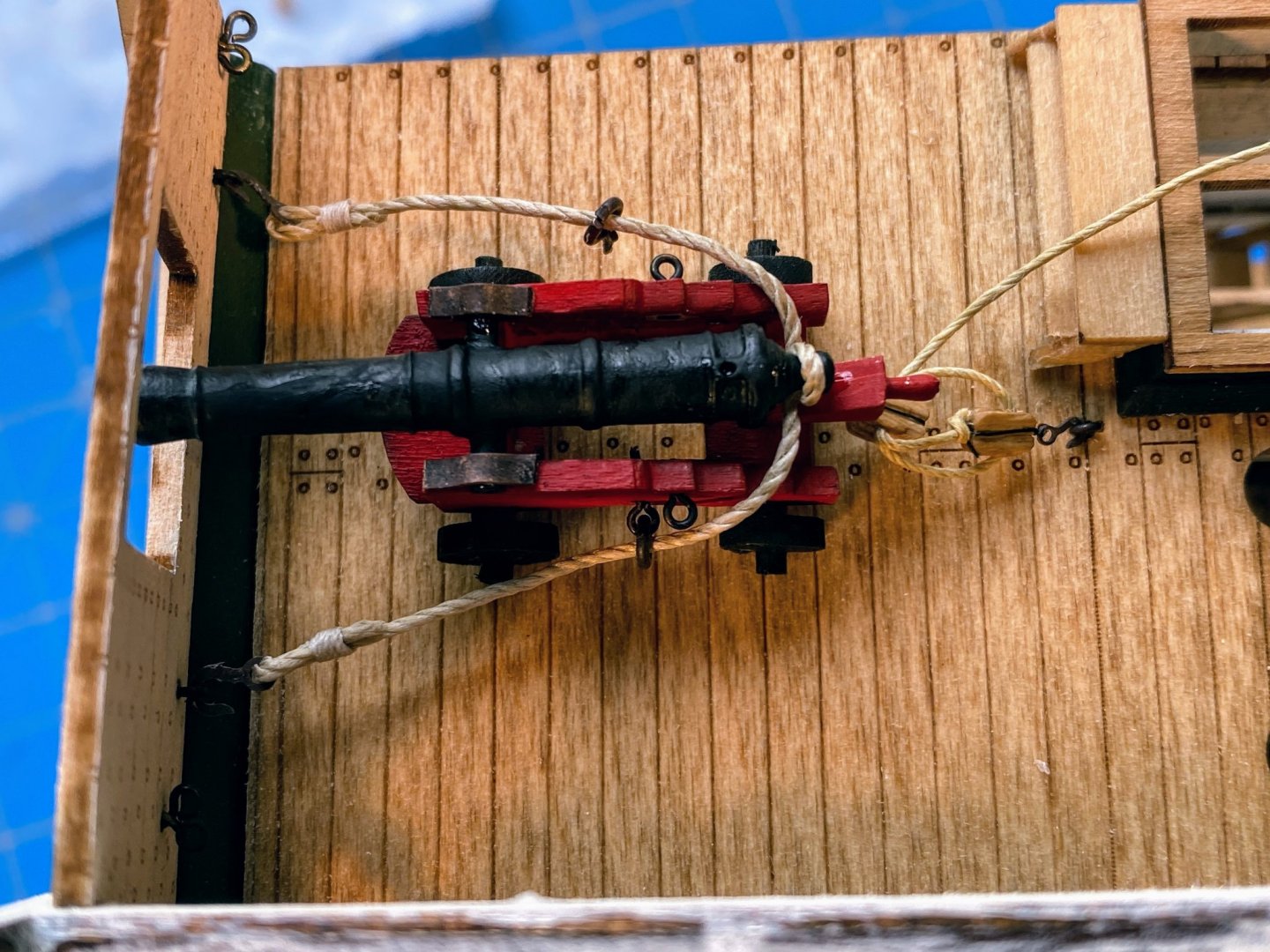
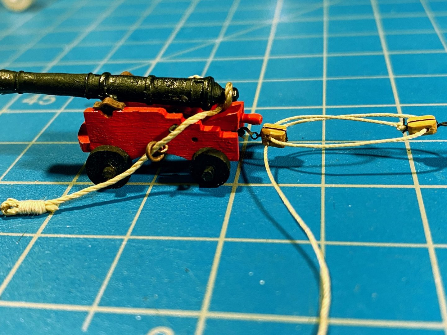
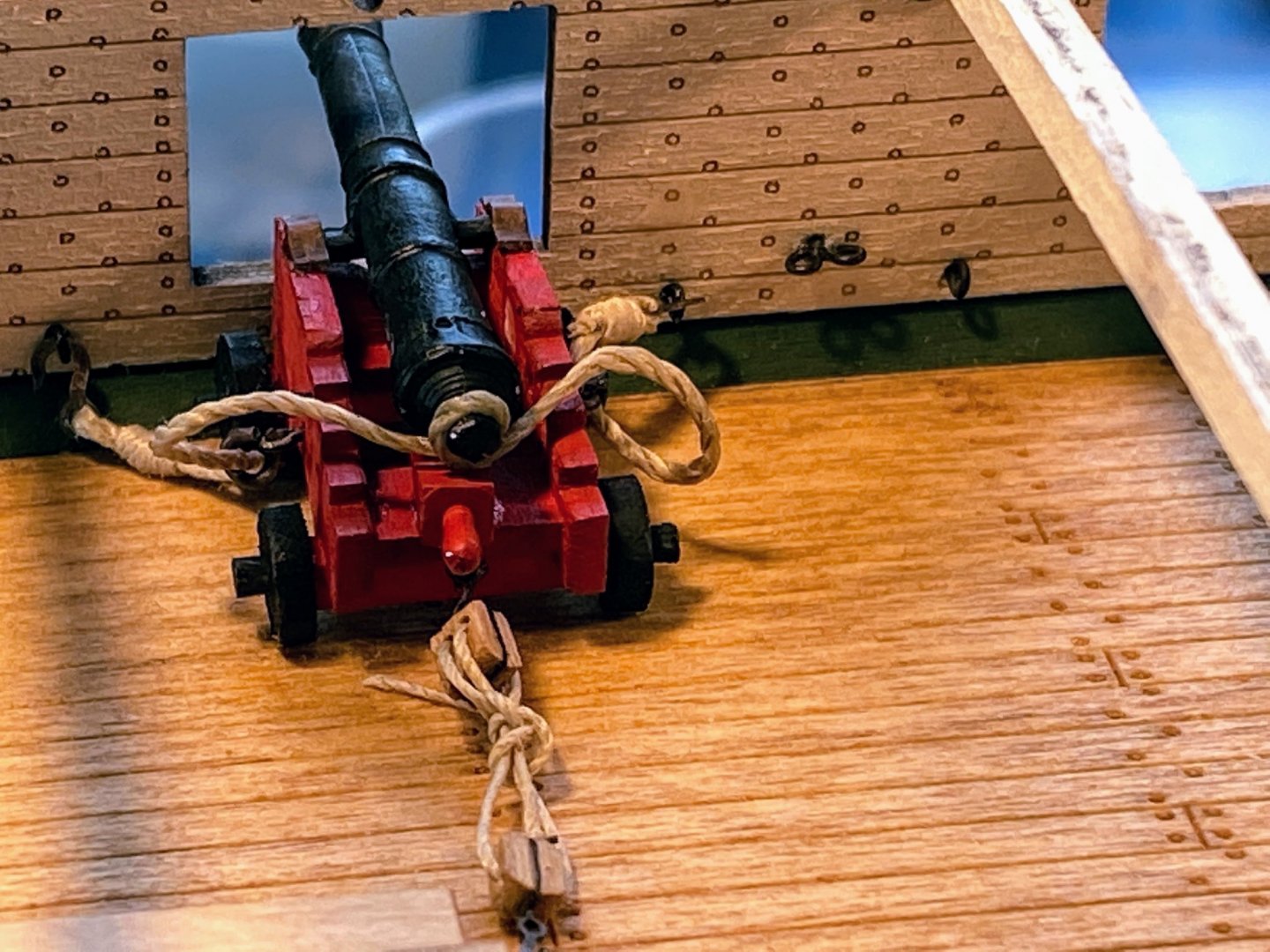
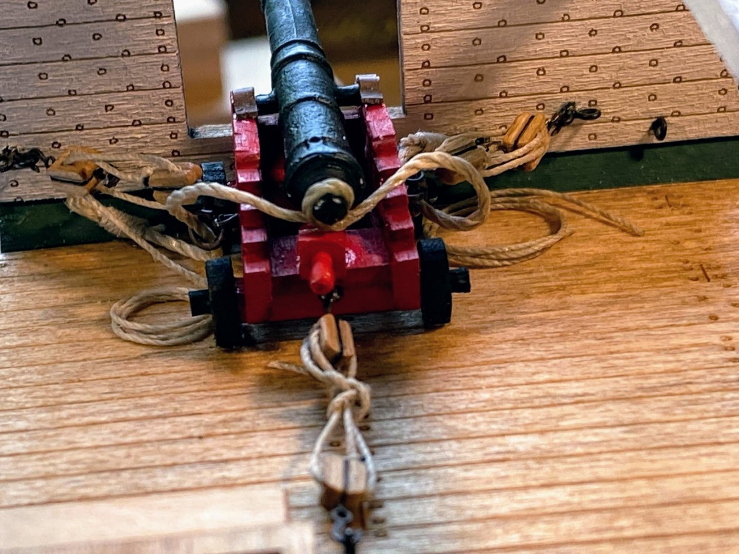
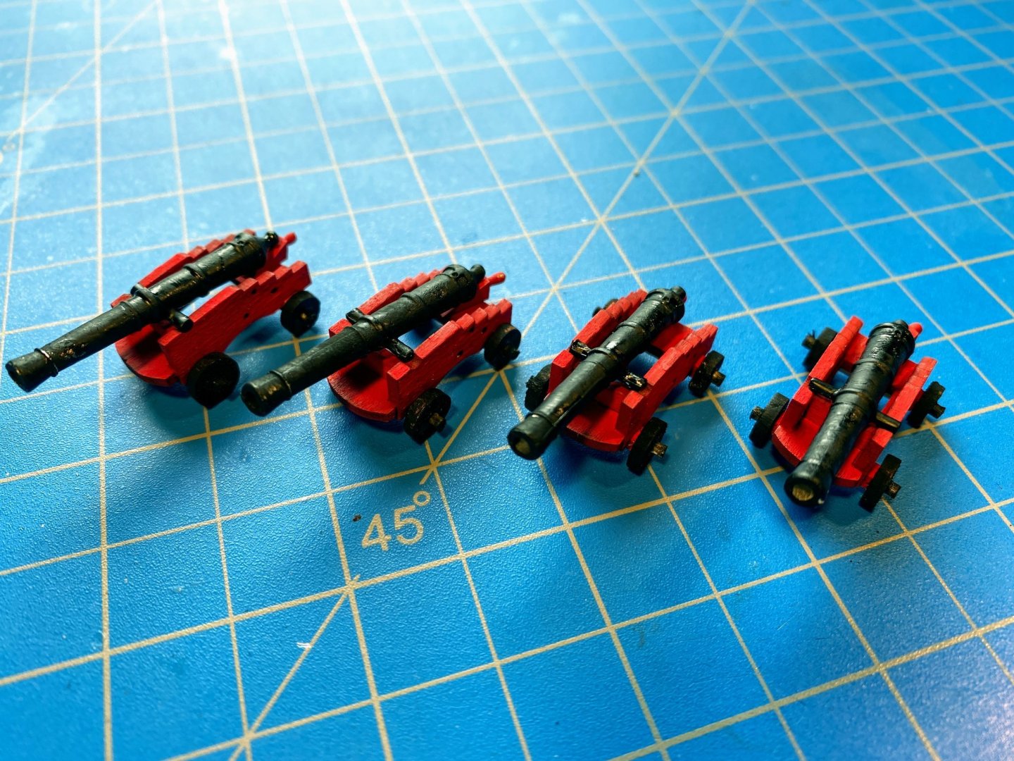
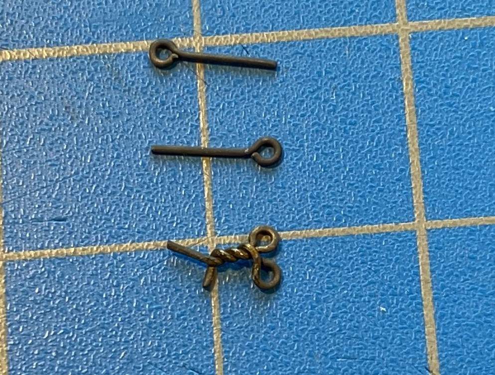
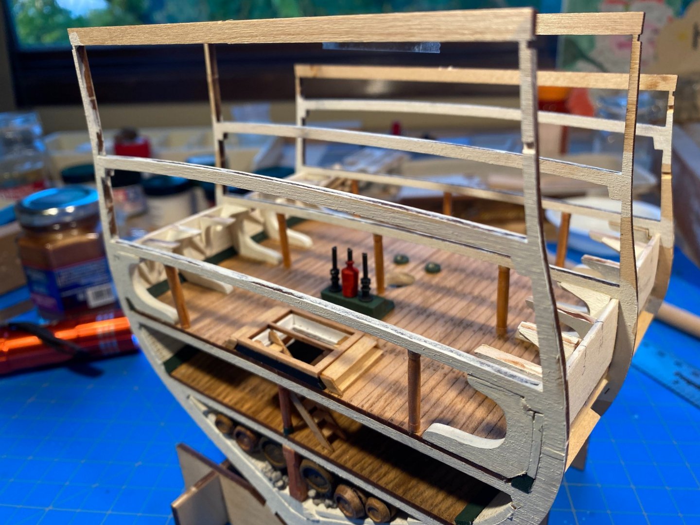
 The gun deck cannons are now complete, and an important decision has been made! I learned a few things assembling and installing the first cannon, and the next three went more smoothly. I found some slightly more pliable thread for the breeching line (or maybe I was just in a glass-is-half-full mood) and whipped hooks onto either end so that the line was 3½“ long. 2 out of 3 times I remembered to slip a couple of split ring/eye bolt assemblies on to the thread first. Then as shown below, I used a mini clamp to hold the gun barrel upside down, wrapped the breaching line tightly around the protrusion at the back of the barrel, and applied a small drop of medium thickness CA. Worked like a charm. Next I bent six trammels from the supplied strip of brass, then after the photo below, trimmed them to proper length and blackened them. As I did with the first cannon, I glued the barrells to the carriage, and glued the breeching line split ring/eyebolts in place, taking care to assure that the front end of the barrels was the appropriate height. Then I glued the trammels to both the carriage and the cannon axles or trunnions. Next I rigged three train tackles, and hooked each to the eyebolt at the back of the carriage, applying a tiny drop of thin CA to where the hook meets the eyebolt. With that all done, I finally glued the quoins in place, leaving that for last since I did not want to have to try to hook the train tackles to the carriage eyebolts below the protruding quoin above. Incidently the instructions have you build a jig for holding blocks in place when rigging, a jig with two short stubs of wire, affized to the end of a piece of wood, to put through the hole(s) in the block. The "jig" I've always used is a lot easier to assemble, works with any size block, and is recycleable! 😊 I finally made the big decision (discussed several times in previous posts): I am going to cut away the spar deck and some of the framing on the starboard side (left side in the photo below) to make some of this gun deck work more visible. And I will show the cannons on that side of the gun deck in their stowed position, with the gun port lids closed. In the photo below these three cannons are dry fit in place (the first cannon is glued in, on the upper right). Some things to be addressed when these three cannons are glued in place. The breeching line for the cannon in the upper left is a little too short to allow the cannon to be pulled inboard as far as it should be. I like Bob Garcia’s “Measure once, cuss twice” advice, and I admire his restraint when it comes to the only “twice” part of it. 😊 Hopefully easily remedied by putting that cannon on the other side of the ship. Also note that I managed to dislodge one of the split ring/eyebolts on that cannon. Then there are the deck eyebolts for the train tackle, which need to be closer to the ship’s center line for the tackles to pull the cannons far enough inboard for stowage. And finally, I think I’ll try to do something about that train tackle on the first cannon. All addressed in my next post.


- 163 replies
-
- 5
-

-

-
- Model Shipways
- Constitution
- (and 2 more)
-
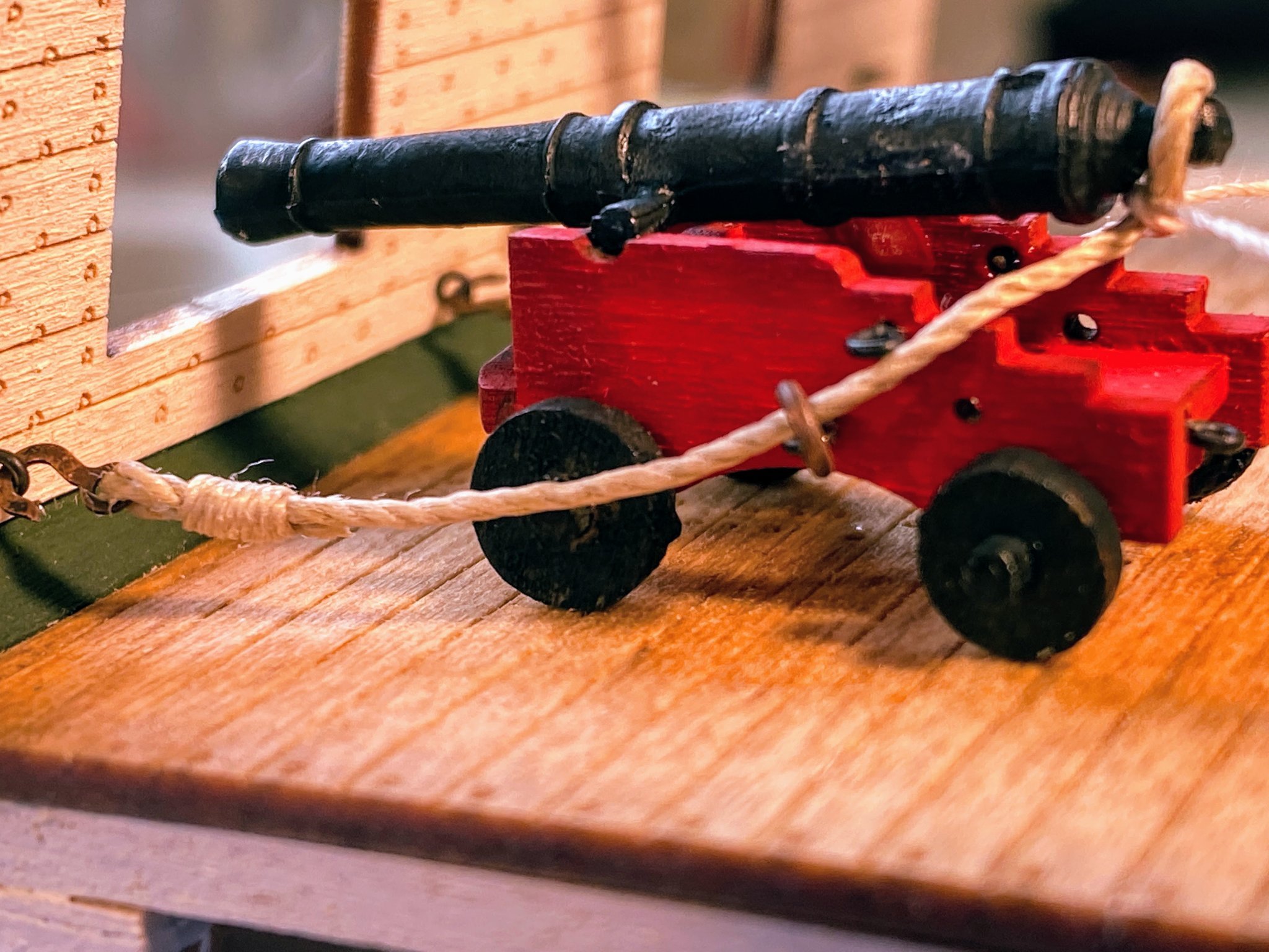
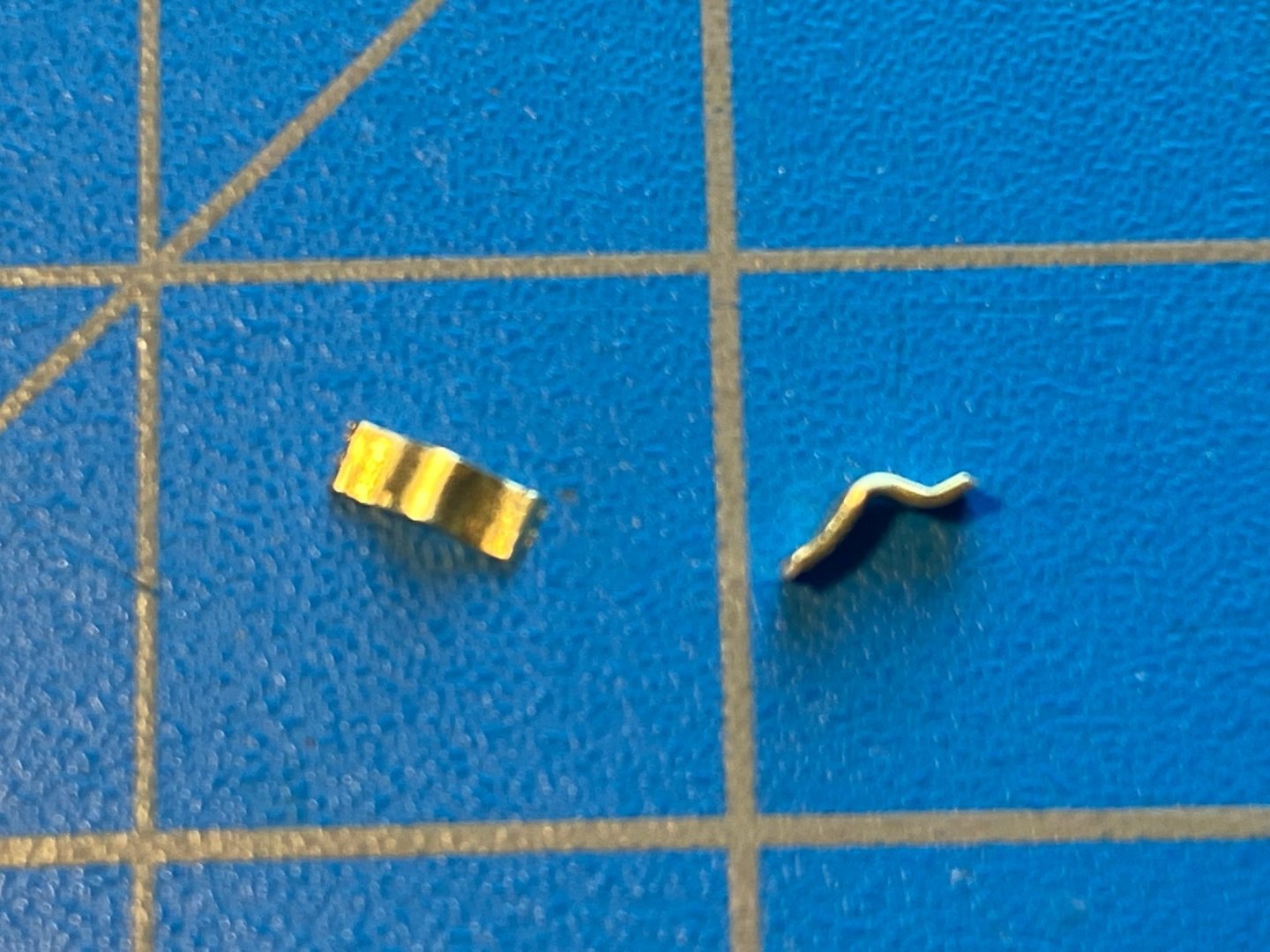
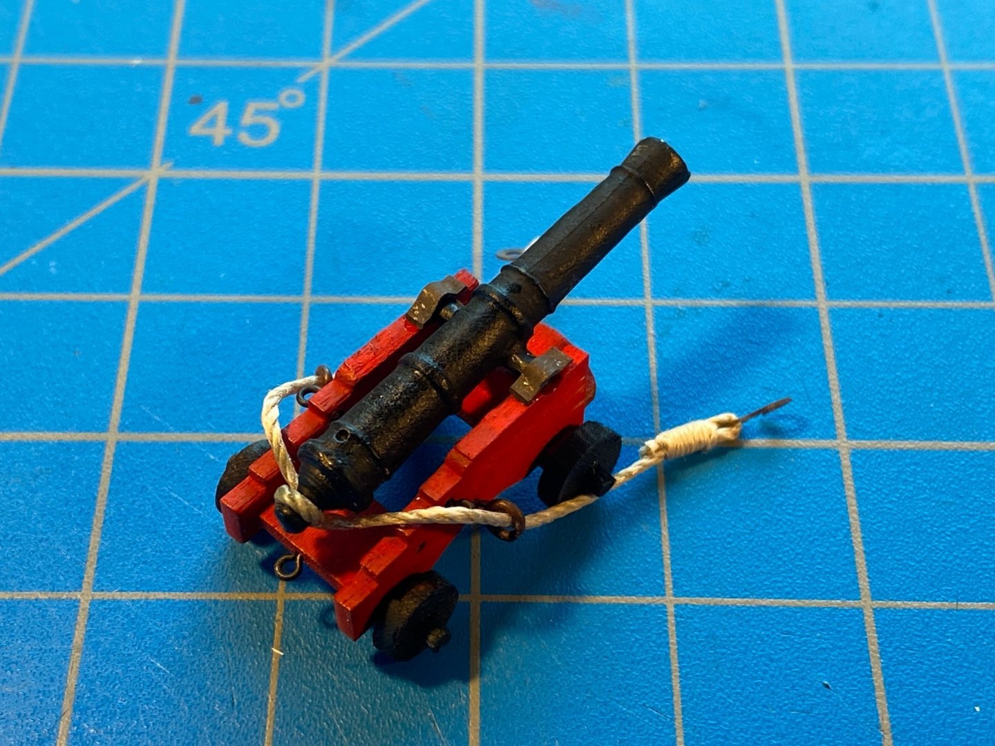
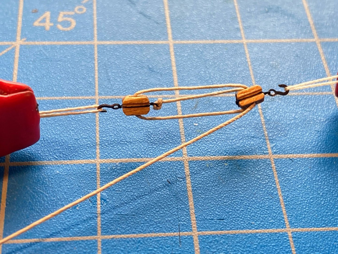
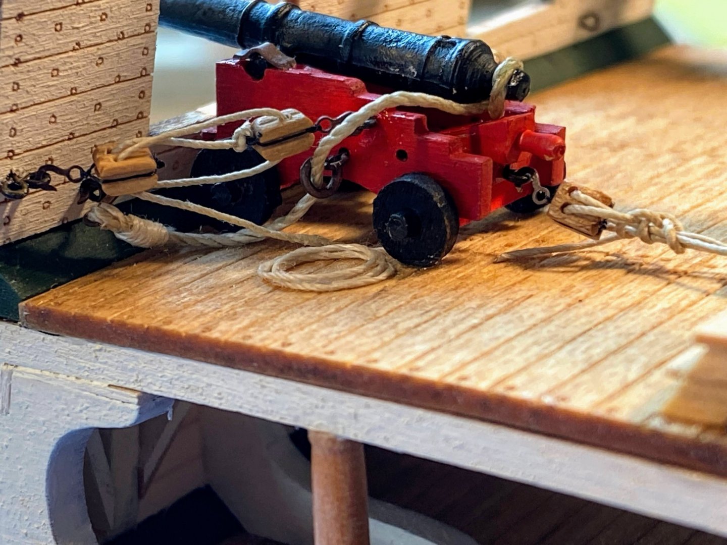
With some difficulty I secured the infamous loop in the breeching line by stretching the two parts of the breeching line taught (dislodging one of the eyebolt/split rings in the process) and applying a drop of thin CA. That worked well in terms of securing the loop, but the glue is so thin that it wicked into the breeching line at least ¼” in each direction, making the line as stiff as a board and considerably harder to work with. For the other three guns, I will use medium CA and try to use a drop that is tiny enough that it shouldn’t wick and won’t be seen. The instructions have you bend and darken brass strips to create the trammels which hold the gun barrel axel (trunnions), then glue the trammels to the carriage taking care to assure that the glue does not prevent the barrel trunnions from rotating. The idea is that the angle of the barrel will be adjusted after the whole assembly is in place, to assure that the barrel is where you want it to be relative to the gun port. That barrel angle is then secured by gluing the quoin in place. For me, that’s making things unnecessarily difficult. I dry fit the cannon back on deck and measured the distance from the deck to the properly placed barrel. Then back on my work bench I glued the barrel to the carriage with the barrel the appropriate height above my bench. I then bent the supplied brass strip with some small needle nose pliers, as can be seen below. The photo reveals how imprecise the bending was, but hopefully I will get better with practice. Once blackened and glued to the carriage and the trunnions, they didn’t look too bad (bare spots on the trammels have been touched up post photo). On to the rigging. I found a great post about rigging cannons here, and used a number of things I learned. Gotta love these forums. The gun tackle, also known as the outhaul, is used to hold the cannon in an outward position until immediately before firing, and upon firing the friction of the line running through the blocks helps absorb the recoil so that it isn’t absorbed solely by the breeching line. The gun tackle can also be used to adjust the sideways aim of the cannon, so it isn’t limited to firing strictly perpendicular to the centerline of the ship. The train tackle, or inhaul, pulls and holds the cannon inward, so the gun port lids can close, as would be the case during the days, weeks and longer when the ship is not in battle. I’m thinking I will rig one side prepared for battle, and one side inboard, as I’ll discuss in a later post. In either event, the free end of the line (the falls) would not likely be neatly coiled in a circle as found on so many ship models, but would likely be cleated (or otherwise secured) and loosely coiled, or simply loosely coiled (the outhaul immediately before firing). So with all of this in mind, I rigged three tackles for my first, recently assembled, cannon. Like the breeching line, the end of each tackle is hooked, rather than more permanently secured, to an eyebolt. The kit’s photo-etched hooks come in two sizes, and the instructions said to use the large size for the breeching lines. It does not say anything about the hooks attached to the tackles. The hooks as shown on the plans all appear to be the same size, but if I used the large hooks for the tackles as well, there would be only two left over, which wouldn’t leave enough to do anything with the guns on the spar deck. So I decided to use the smaller hooks, and leave the larger ones for the breeching lines topside. I did a word search in the pdf version of the instructions, and large hooks are referred to only one other place (a pair of shrouds), so there will be more than enough large hooks left over for that purpose. Almost everywhere in the instructions hooks are referred to without reference to size. The instructions suggest using beige thread to tie the hooks and blocks together. Other kits I have seen have you use blackened wire to strop blocks. I have always used black thread, and I have usually used some very strong fly tying thread I found in my wife’s stash of thread (she did a bunch of fly fishing decades ago, pre-me). I have always assumed that sailing ship blocks are stropped with cable or metal, so black looks better to me than beige. The last thing before cutting the loose ends is to put a drop of diluted white school glue on every knot. Above, I hooked one end of one of the tackles I rigged to the eyebolt at the back of the carriage, and secured it with the tiniest drop of thin CA possible. Then I glued the quoin in place. With everything thus secured, I put a small drop of wood glue on the bottom of each wheel and glued the whole assembly to the deck. I then hooked the back end of the train tackle to the eyebolt previously glued into the deck. With the cannon in the outward direction, the train tackle was at full extension, so I figured the falls should be pretty short. I tied three half hitches around the rest of the tackle, figuring that would be a reliable way to secure it, then cut the line off there. Unfortunately I was unable to make the half hitches look at all realistic, and the train tackle aesthetically is kind of a mess. Finally I hooked both ends of the breeching line to their respective eyebolts. Next I hooked both gun tackles to the eyebolts in the sidewall and to the eyebolts in the gun carriage, and pulled the line relatively tight. That sounds easy, but in the process I managed to loosen the cannon from its carriage once and detach the whole assembly from the deck twice. This was a couple of evenings ago, after a glass of wine, and being a committed morning person, I should have known that working at that hour on this tricky a part of the build was a bad idea.😊 I cut the loose end of the gun tackles short, then made a couple of loose coils which I glued (diluted white glue) to the deck, hiding the short loose end of the tackle. I found making the coils to be pretty straightforward -- I’m fortunate enough to have done quite a bit of sailing in an earlier life, and if you know how to give rope a half twist with each coil, the same thing works with thread. I simply held the growing coil between two fingers and applied diluted white glue to the whole coil once completed. Of course I haven’t figured out how to do that while taking a picture. Below, the coil on the starboard side is, IMHO, too large, and I like better the one I made second, on the port side. Overall I’m not particularly pleased with this cannon rigging. Both the breeching line thread, and the thinner tackle thread, are too stiff and do not fall naturally. Also, the blocks look too big. The parts list shows the smallest and most numerous blocks to be 3mm, but in fact they are 4mm, the same length as the handful of blocks identified as being 4mm, except that the latter are slightly thicker. Also I’m concerned that the train tackle is too short to pull the cannon all the way in if I do in fact choose to display one side that way. I will have to do some experimenting with different thread, perhaps find some smaller blocks, and if the result is materially better, maybe tear this cannon out and do it over (perish the thought). Or maybe I'll decide that I have to stop looking at close up photos of my work and view it as I would from a distance without magnification.

- 163 replies
-
- 8
-
-
- Model Shipways
- Constitution
- (and 2 more)
-
Thanks Gary. The instructions refer to those as trammels, and I'm working on a fairly lengthy post (probably to be posted tomorrow morning) that provides my take on those pieces and on rigging the cannons. In all the pictures above, the barrel is not yet glued to the carriage and the wheels are not yet glued to the deck. With regard to wetting and drying rigging thread before using it, I read about that trick a year or so ago (and wondered why I hadn't learned about it sooner). I have used it ever since and have found it to do an excellent job of getting rid of the creases and curles thread has when it comes off of whatever it is wrapped around. But other than that, I haven't found that it makes the thread less stiff or easier to work with. Earlier today I took your use of the word "soak" to heart, and let some thread sit in water for 15 minutes or so, but at least with the thread I tried, that didn't seem to make much difference. Should I soak it longer?
- 163 replies
-
- 1
-
-
- Model Shipways
- Constitution
- (and 2 more)
-
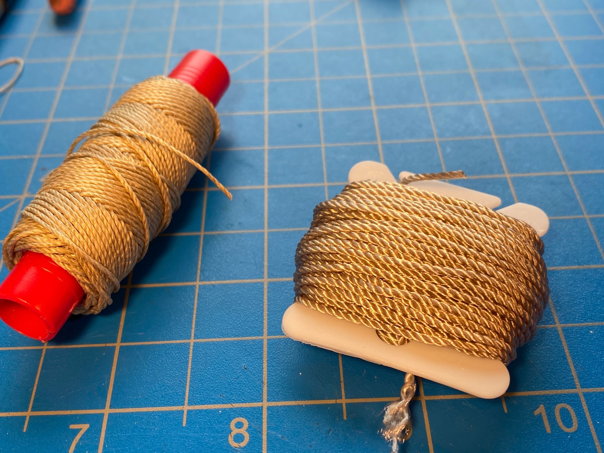
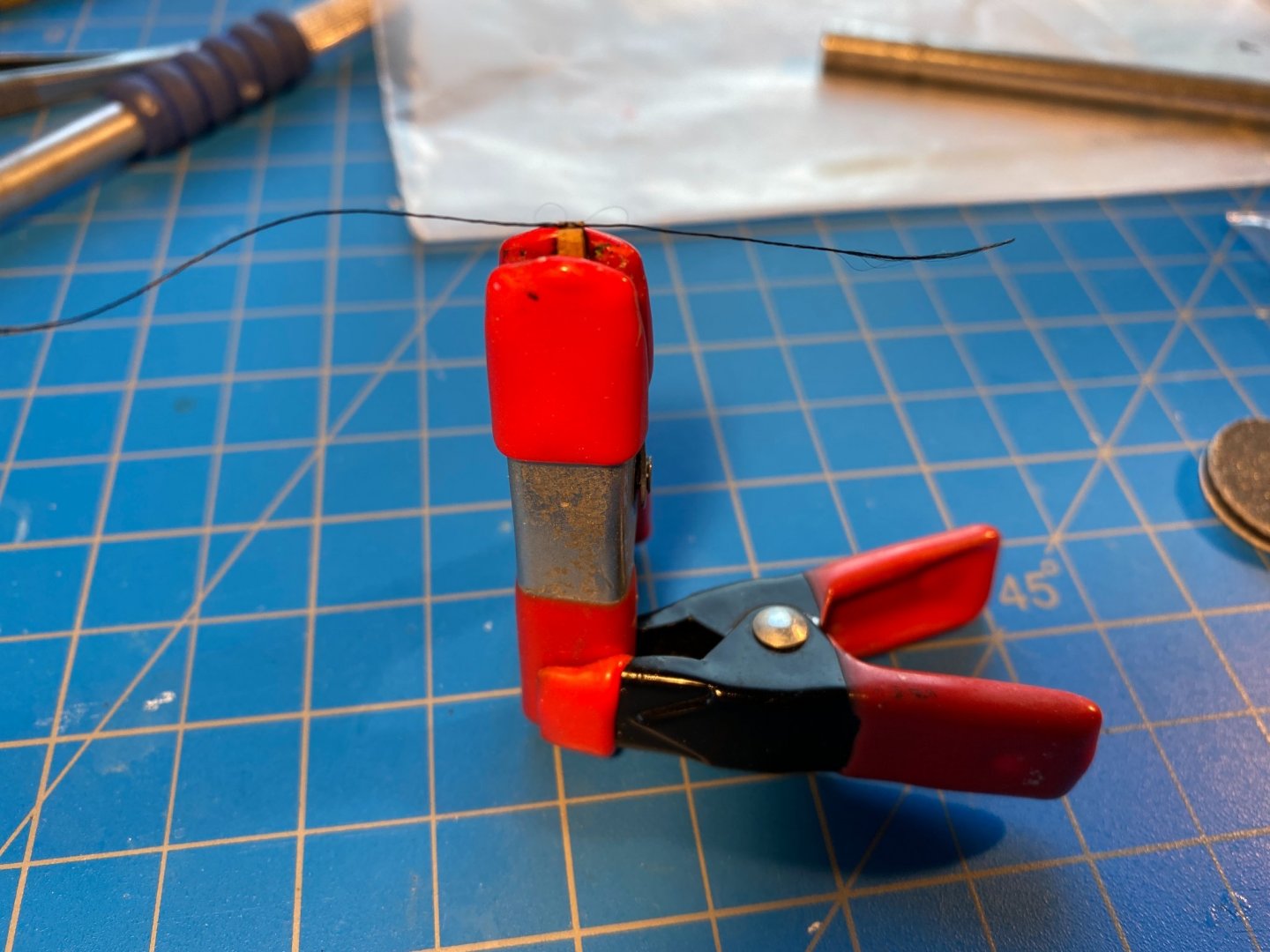
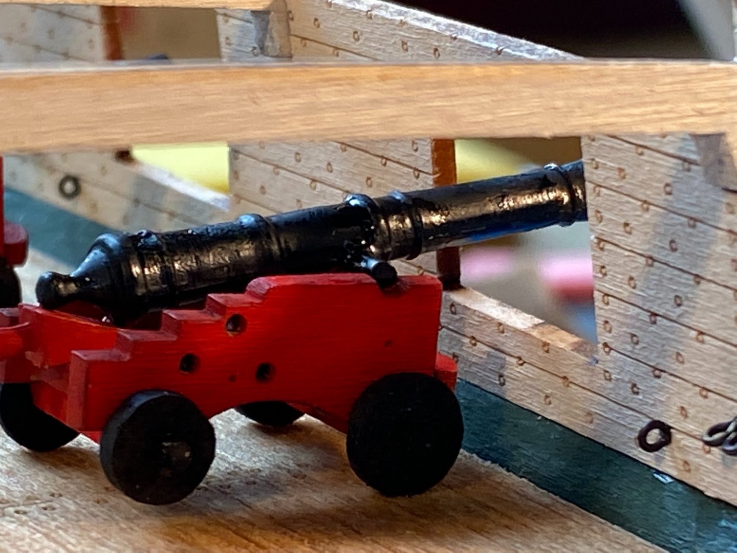
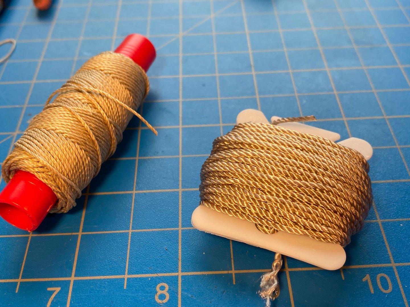
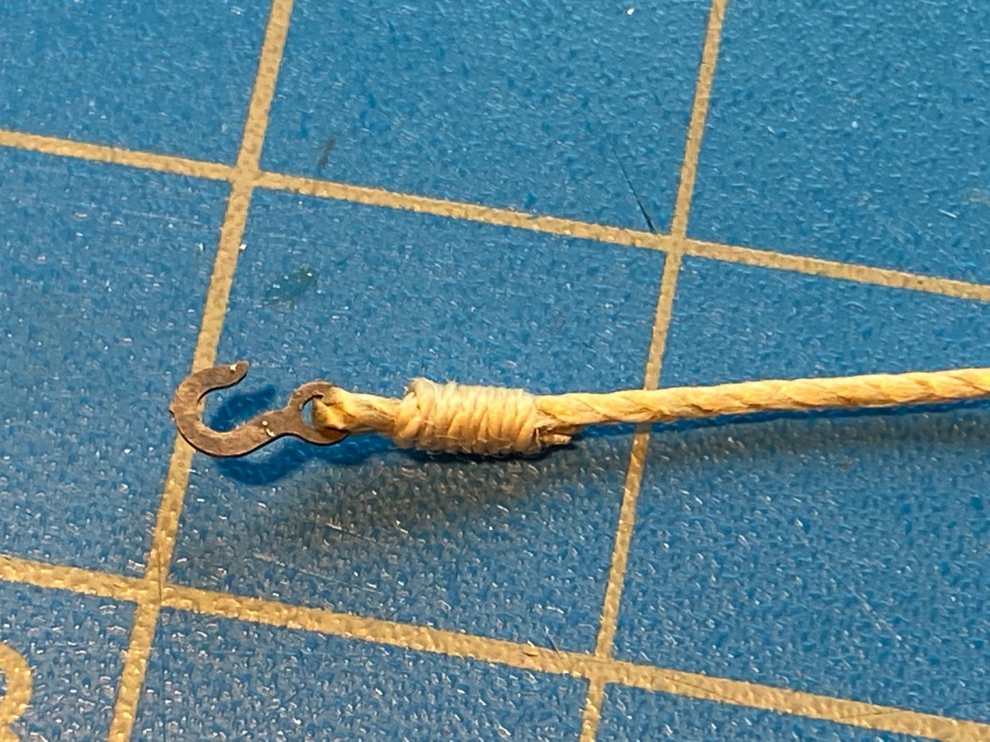
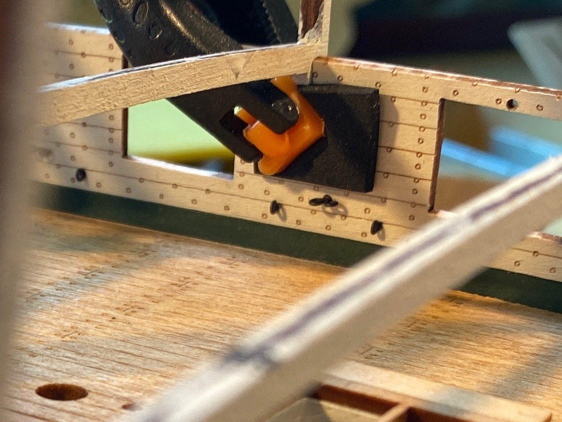
Below I have glued the long gun carriages together, and painted them, the guns and the wheels. I glued the wheels on, dry fit the guns, the carriages and the quoins, and placed (but not glued) them on the deck. Looking at the pictures I can see that some touch up painting is needed. After taking these pictures, I did some paint work and glued in the eyebolts for the gun tackle and the train tackle. I did not glue in the eyebolt/split ring assemblies just yet. Rigging these things will be the next challenge. First a word or two about rigging thread. My humble opinion, but I find Model Shipways tan thread to be too light in color and too shiny. Admittedly the MS rope texture is superior. For some reason the picture below makes the color and shininess look better than it really is. And in this case, the designated thread for the breeching line is too thick and stiff for me to work with, especially where it is supposed to wrap around the back end of the cannon. I have some Amati thread I like better (wrapped around the red tube), and I found some online and ordered a bunch for this build. Each end of the breeching line is secured to the sidewall with a hook, photo-etched brass and needing to be blackened. I used some smaller thread to secure a hook to one end of the line, slipped a couple of eyebolt/split ring assemblies onto the line, then secured another hook to the other end. A drop or two of diluted white glue was applied to each lashing. I then cut the eyebolt stems shorter, and glued them in place on each side of the carriage. Then I tried to loop the line around the knob at the back end of the cannon, which proved to be a challenge. As you can see below, I tied some thread around the looped part of the breeching line in an effort to make it a tight loop. I then hooked the hooks into the eyebolts on the sidewall. None of it is glued in place yet, and my next task will be to unhook the ends of the line from the sidewall and bring the gun assembly back down to my work bench where it will be easier to work with. I suspect some diluted white glue will do the trick with regard to that loop. For the other three guns, I think I will get that loop done the way I want it before gluing the eyebolt/split rings in place. The good news is that I got the length of the breeching line just right (and measured it), so the gun can be displayed battle-ready (front wheels against the waterways and barrel sticking out the gun port) or back far enough to enable the gun port hatches to close.


- 163 replies
-
- 7
-
-
- Model Shipways
- Constitution
- (and 2 more)
-
Very well done, and you have every reason to be proud. No need to focus on the occasional minor hiccup. I sometimes use photos to check something out that my eyes may not be good enough see well, but the risk is I'll discover something I'd just as soon not be aware of. It's all part of the hobby. Keep up the good work. Tom
-
Macro photos with an iPhone
Tomculb replied to Tomculb's topic in Photographing your work. How to do this.
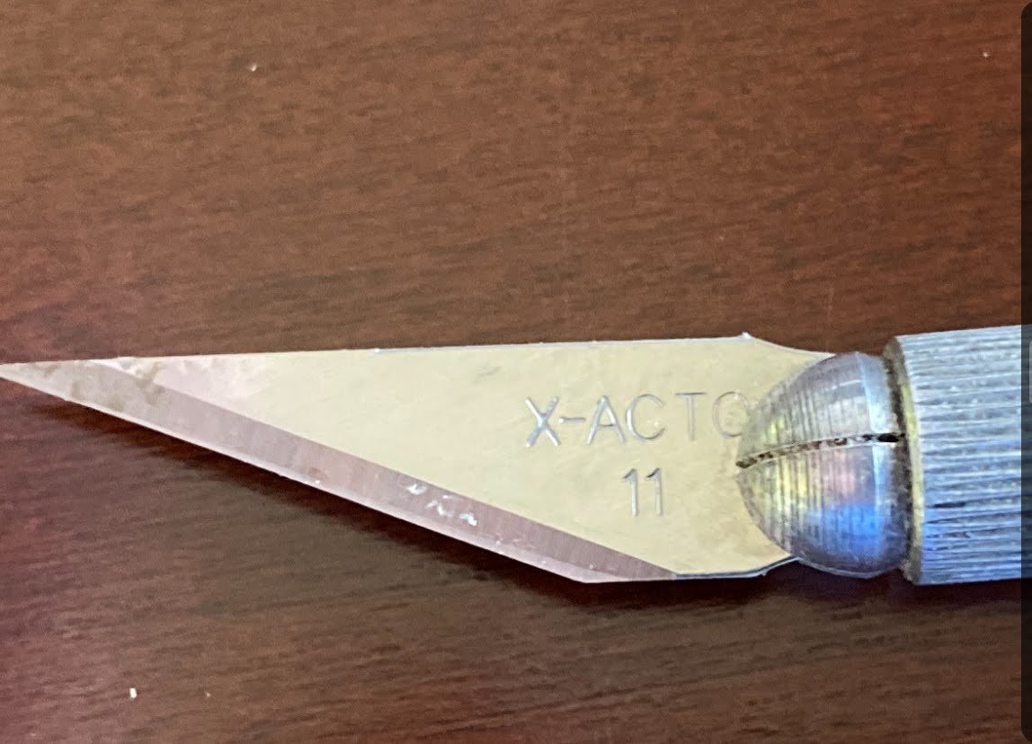
Jan is right, you can get close ups simply by zooming with the camera, but the article I read about the method described above says that you can zoom in closer using the magnifier tool. I fooled around with my phone a bit and there is no question, you can get a closer detail photo with that tool. You can get close enough that it becomes difficult to hold the phone still enough. Why you can zoom closer with the magnifier than you can with the camera makes no sense to me, but it certainly appears to be the case. So going forward, I intend to try to get as close as I want with the camera, and if that isn't enough, I'll use the magnifier tool. With all of that having been said, the iPhone does not have a true macro lens. All you're doing is taking a small portion of the picture and blowing it up, with the result that the resolution gets lower and lower the closer you zoom in. Inadequate for professional purposes, but good enough in my view for pictures of tiny parts and small detail on a model. -
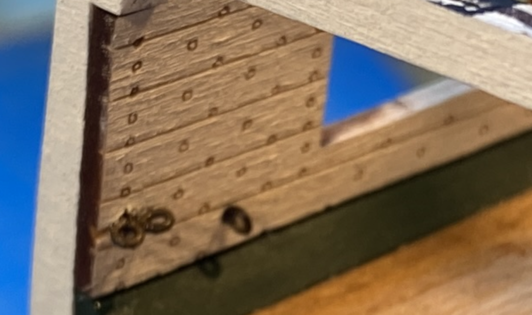
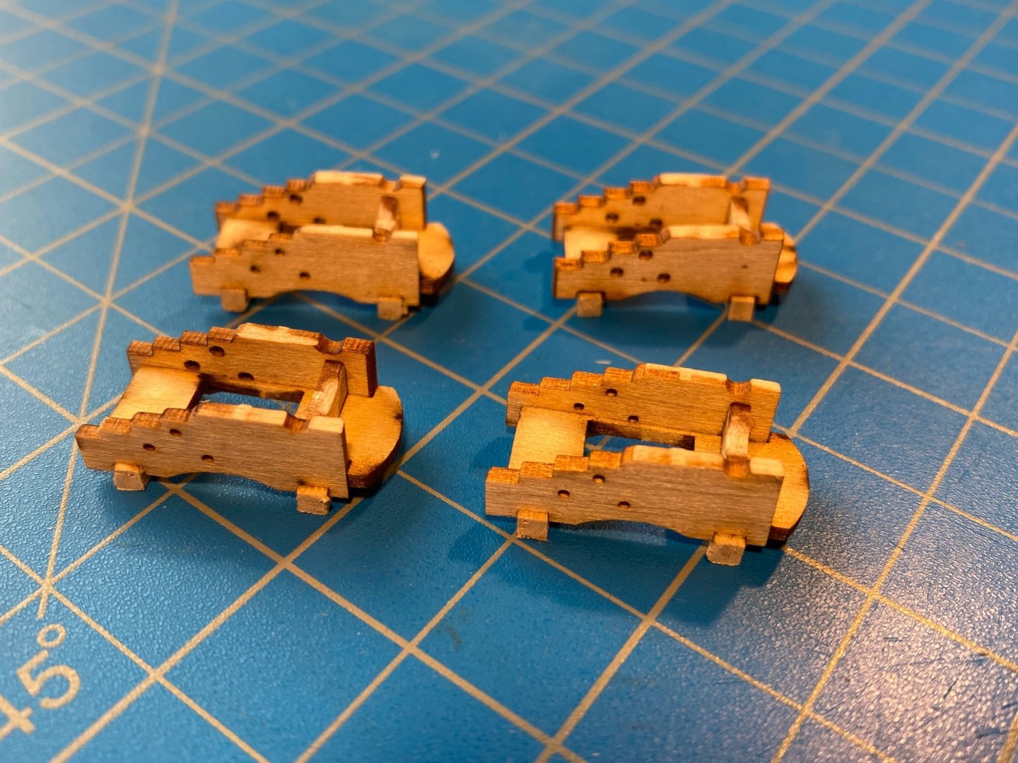
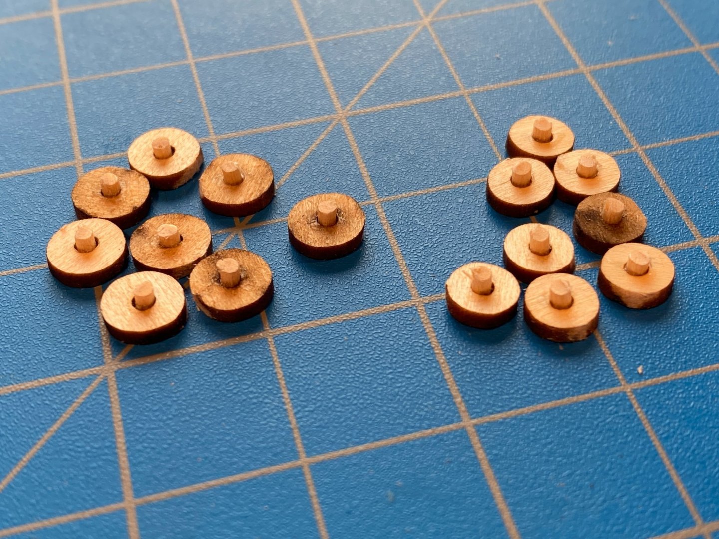
The kit does not come with pre-bent eyebolts, but fortunately I have maybe as many as a hundred of them left over from previous builds. I think I may have even bought an extra bag of them years ago. In any event, I'm far too lazy to bend them myself from the supplied wire, as the instructions direct. I used Blacken-It to blacken them, and I'm getting close to finishing a bottle of the stuff I bought some 30 years ago! The gun tackle is secured to the sidewall with double eyebolts, which I created by twisting two eyebolts together. The excess in the first photo below obviously will be cut off. Each cannon's breaching line requires an eyebolt on either side, and the ends of each cannon's gun tackle share a double eyebolt with the adjoining cannon. That corresponds with the pre-drilled holes in the sidewalls, meaning the additional eyebolts shown in the instructions but not shown on the plans shouldn't be necessary. Also pre-drilled in the sidewalls are holes centered above each gun port . . . I still haven't figure out what those are for. The instructions have you install the double eyebolts into the bottom of the yet-to-be-installed hanging knees, but the plans show them installed into the sidewalls just below the bottoms of those knees. I chose to follow the plans and not the instructions. With just a little sanding and trimming, the sidewalls fit nicely in place between the waterways below and the ribs above, and once dry fit to my satisfaction I glued the eyebolts in place in one sidewall. Dry fitting that sidewall again I realized that the aft double eyebolt aligns with the aft rib (which should have been obvious to me earlier but wasn't), and on the back side of the sidewall I had a nice glob of brass and CA glue where I needed a smooth surface. I was able to remove some of the "glob", but I also found myself digging a gouge in the rib to accommodate the part of the glob I found too difficult to remove. With the opposite sidewall, I didn't glue that double eyebolt in until the sidewall was glued in place, and then I cut the eyebolt quite short so that it didn't interfere with the rib. EDIT 9/21/21: While I did some trimming to get the sidewalls to fit in other places, I did not notice that they extend at the top above the bottom of the deck beams, meaning the spar deck framing will extend above the rib, and there will be a noticable gap between the deck and the beam at either end of the build. For some reason I didn't notice this until after I had installed the knees, even though it looks pretty obvious in the picture below. Trimming the sidewalls before installing them will save a lot of headache later. Sanding the knees now is likely to dislodge some of them, to say nothing of being a lot of work. Instead, I will need to thin the framing pieces. I haven't mentioned anything about this problem in the current part of this log because I haven't actually done the corrective work yet. I painted a bunch of knees, but decided that it will be easier to install the knees around the installed cannons than to do it in the opposite order. As Gary as has experienced, I'm not expecting hooking the guns' rigging lines into the eyebolts to be an easy task, and I want as much space to work with as possible. Now onto the long guns. All the laser cut pieces fit together quite nicely. The instructions refer to small and large wheels, which at first I thought was a mistake since the actual wheels are closer in size than the photo in the instructions would lead you to believe. But looking at the plans more closely, I realized that the forward wheels are indeed slightly larger than the rear wheels, and the laser cut wheels are indeed of two sizes. In the second picture below you should be able to see that the wheels on the left are larger, but the difference is pretty small. The axles are cut from 3/32" square stock, and the instructions have you round the ends of each axle, so the wheels can then be slipped on. I chose instead to cut the square axles shorter and find a dowel that would fit in the holes in the wheels, and then cut 16 short pieces to glue into each of the wheels. Once painted, I will glue the wheel assemblies onto the ends of each square axle.
- 163 replies
-
- 3
-
-
- Model Shipways
- Constitution
- (and 2 more)
-
Thanks Gary. I'm finding that the plans and the laser cut pieces are pretty consistent and usually correct (IMHO), and the instructions to be occasionally out of sync with reality. And so far, the laser cutting has been exceptionally good. As I'm about to report below, I installed eyebolts only where there were holes in the sidewalls; those are sufficient to fully rig the long guns.
- 163 replies
-
- 1
-
-
- Model Shipways
- Constitution
- (and 2 more)
-
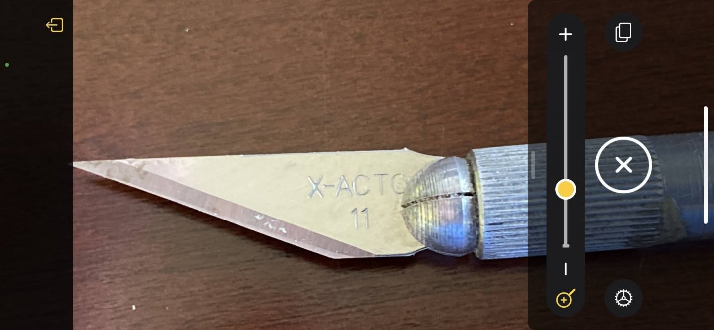
Apologies if I am the last guy on the planet (or at least these forums) to know this, but I just discovered how to take macro photos on my iPhone. First go to the Magnifier tool, found in your Control Center, which you get to by swiping down from the upper right corner of the screen. I understand you may have to activate the tool by going to the Accessibility settings. In the first photo below (my Control Center), it's the button at the bottom with the magnifying glass. Then use it to zoom in on what you want to photograph, push the button at the bottom of the screen (or side if you're holding the phone in landscape mode) to take a "picture" (in quotes because it's not saved with your photos yet. Then take a screen shot (right button and upper left button on the sides of the phone). You can then find the screenshot in Photos, or Google Photos, or whatever, and crop it as desired. Undoubtedly not professional quality, but plenty good enough to post photos of tiny parts on these forums.

-
Gary, a minor question . . . as I'm putting eyebolts in the sidewalls before gluing the latter in place, I'm finding discrepancies between the instructions and its pictures on the one hand, and the plans and pre-drilled holes in the sidewalls on the other hand. Following the former would require drilling holes for an additional eyebolt on each side of each gunport, eyebolts which as far as I can tell will never be used. I'm inclined to follow the plans and just put eyebolts in the pre-drilled holes, and I don't think that will leave me needing two more eyebolts to be installed later (and with much difficulty, wishing I had installed them now). Am I missing something?
- 163 replies
-
- 1
-
-
- Model Shipways
- Constitution
- (and 2 more)
-
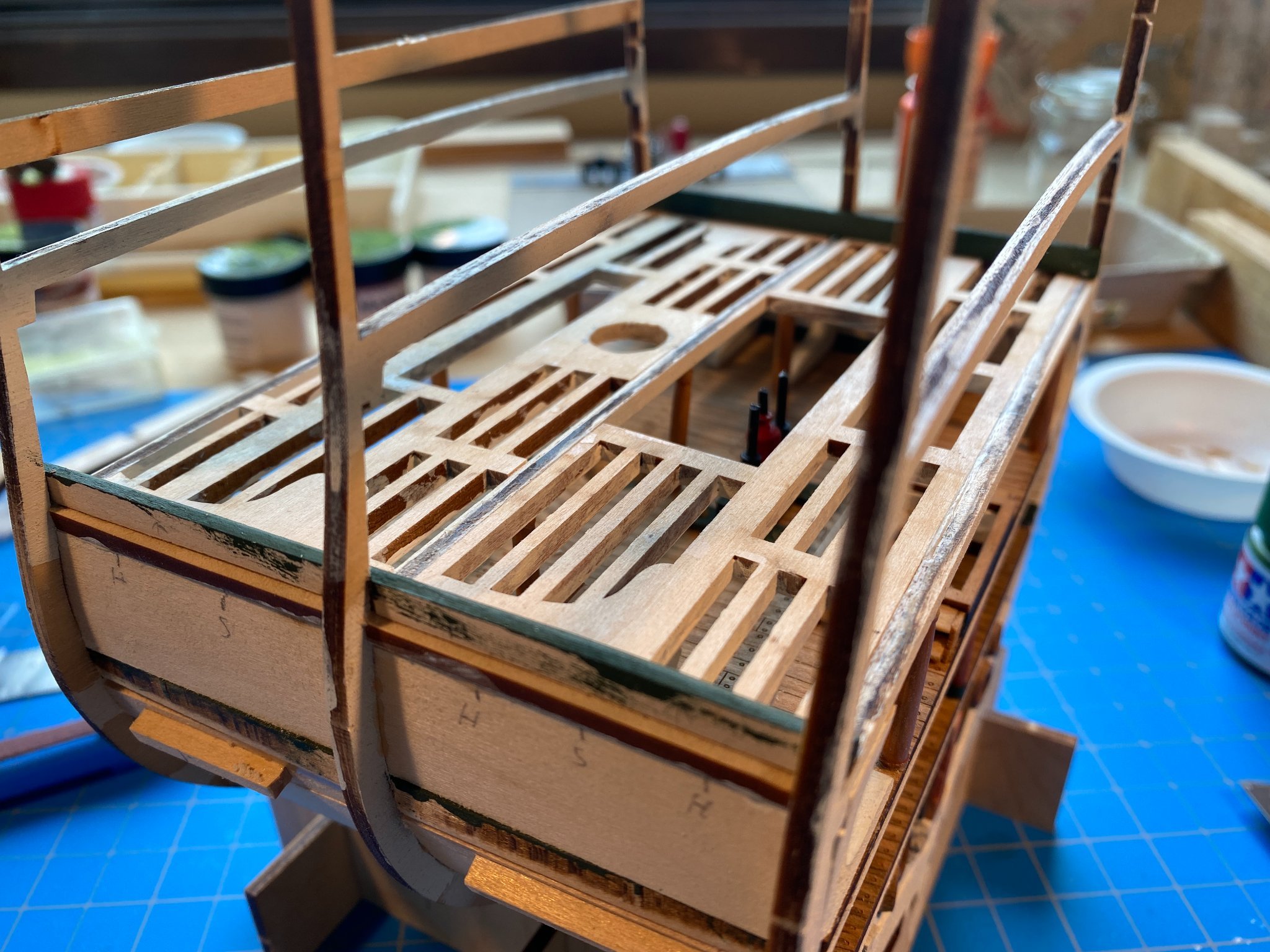
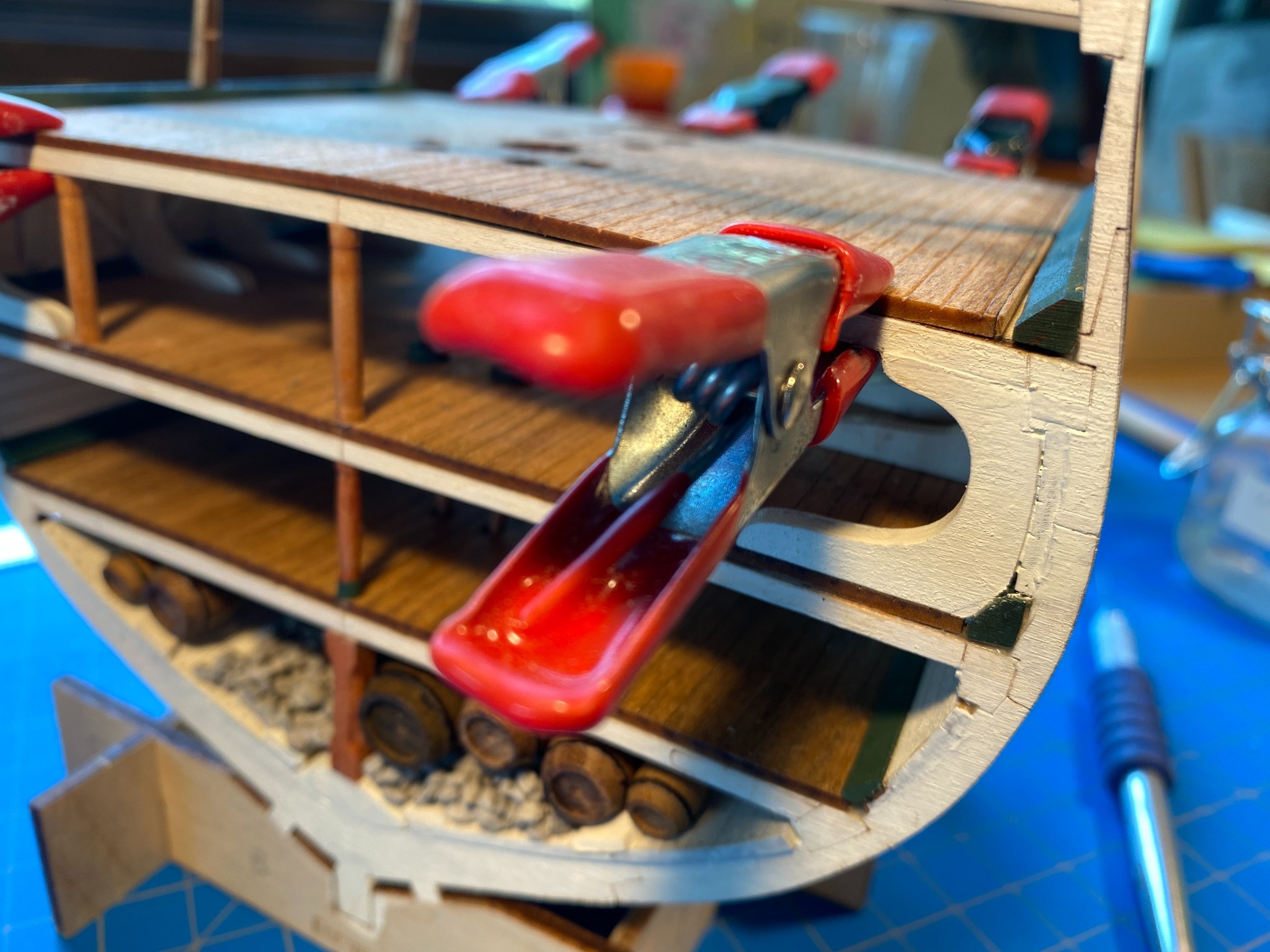
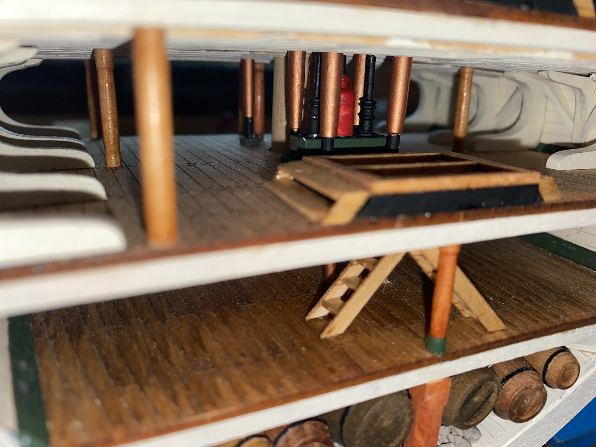
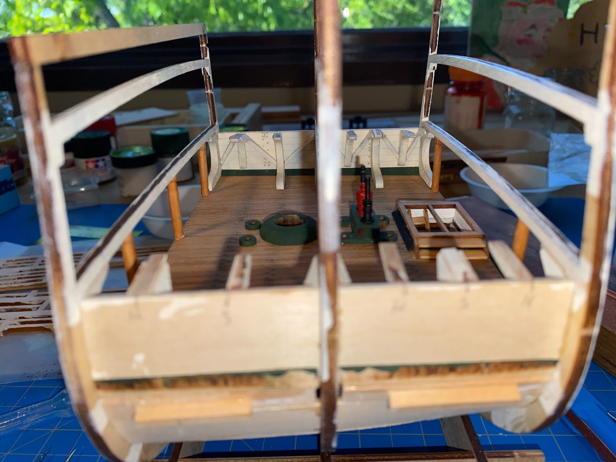
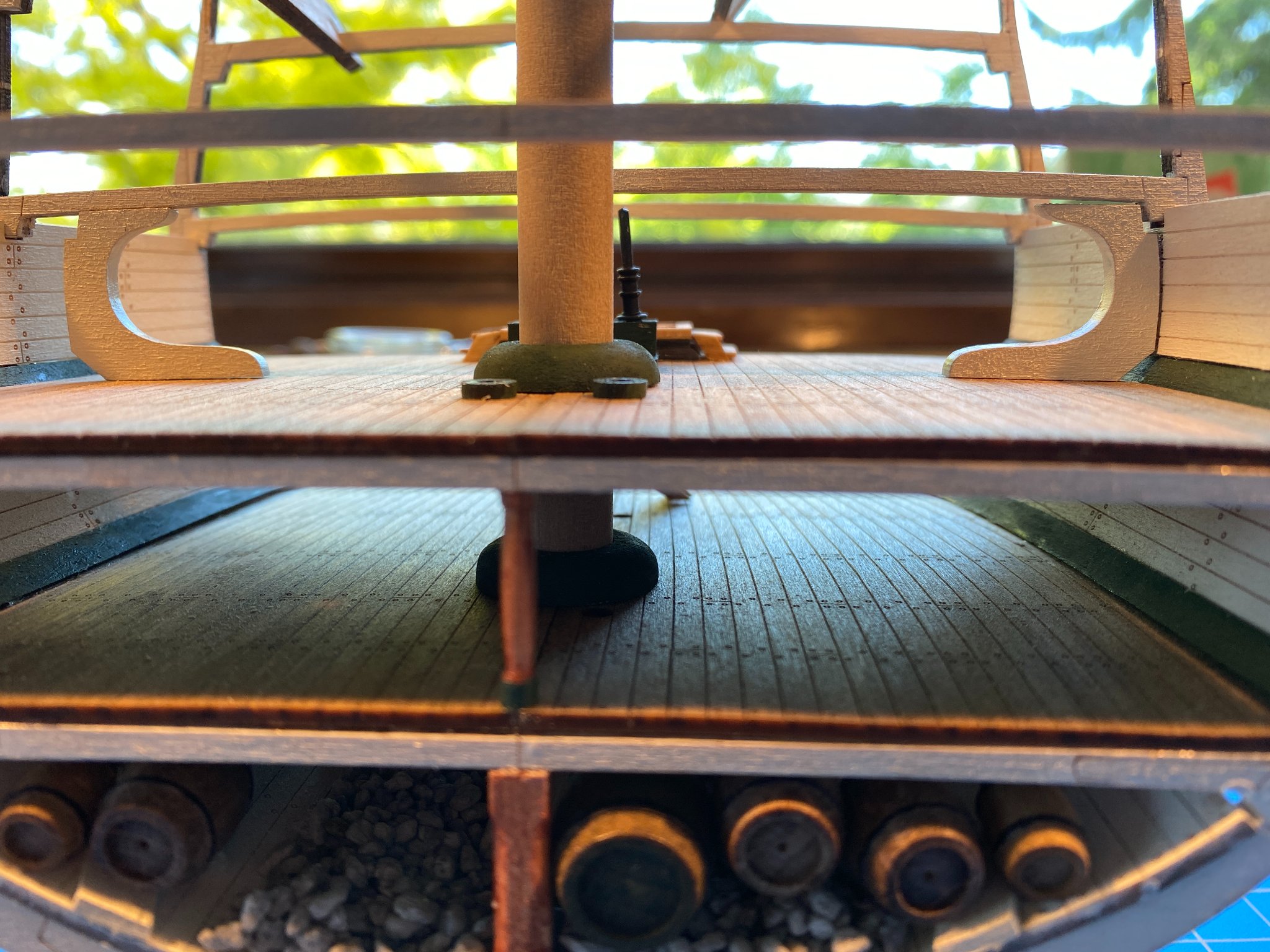
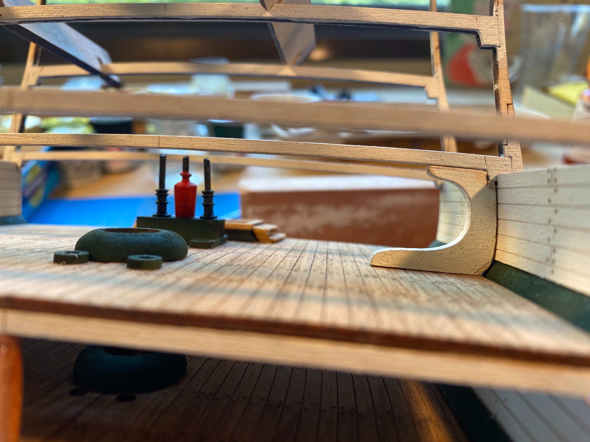
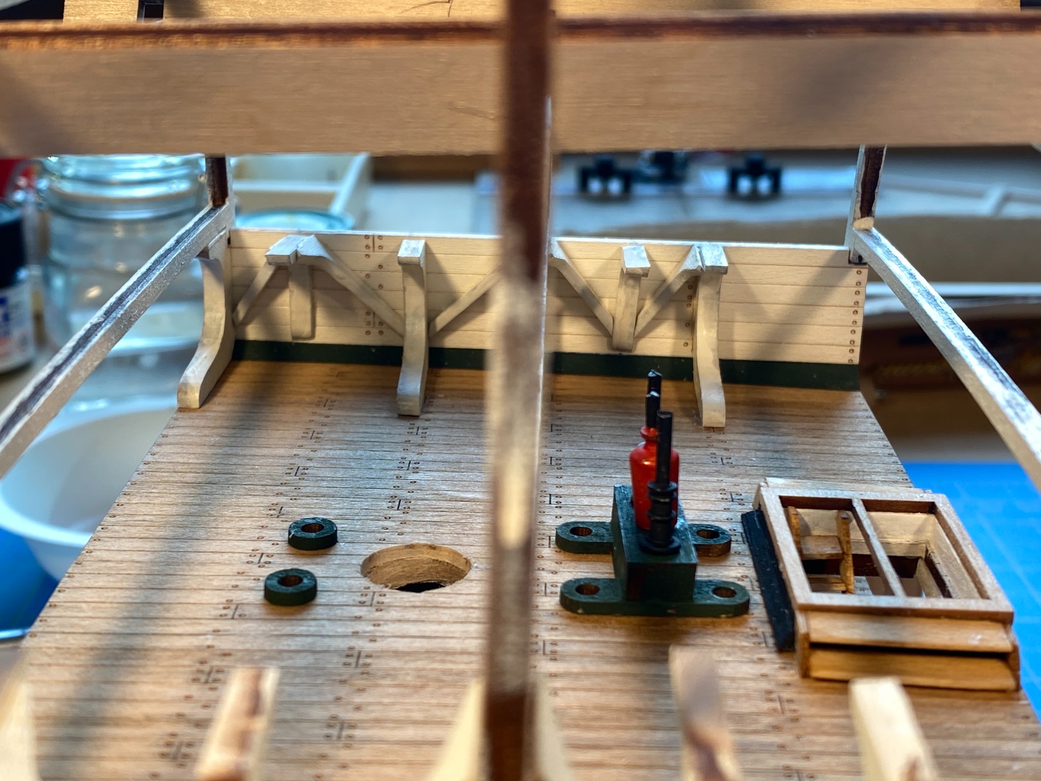
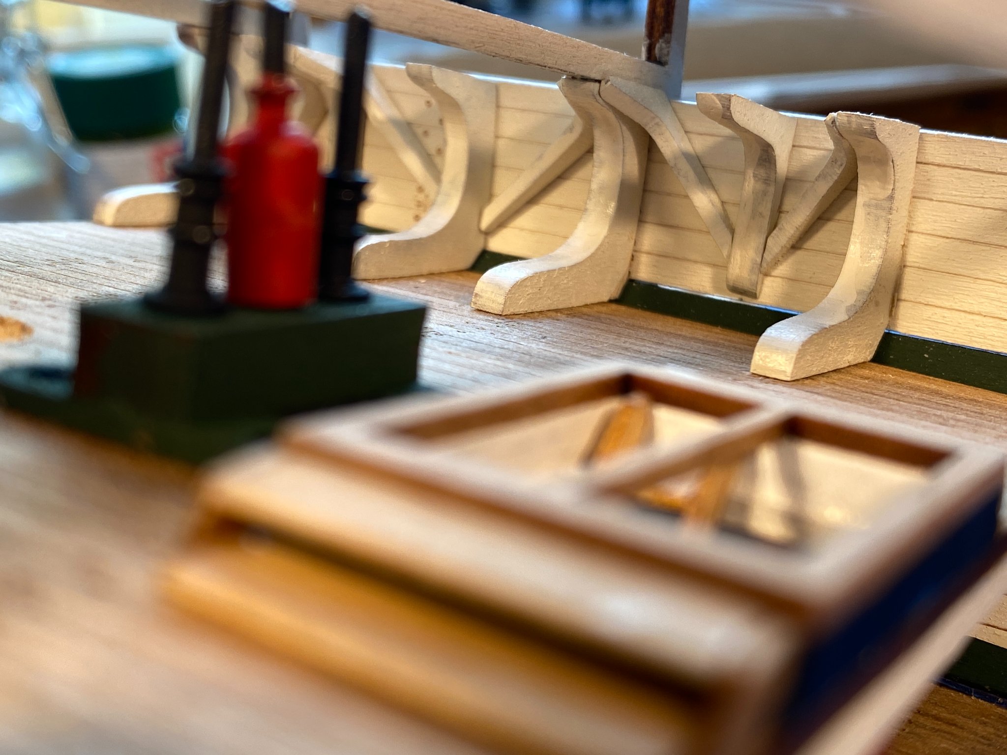
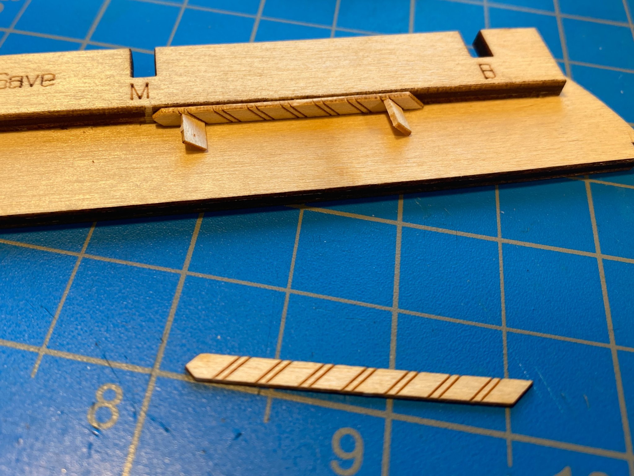
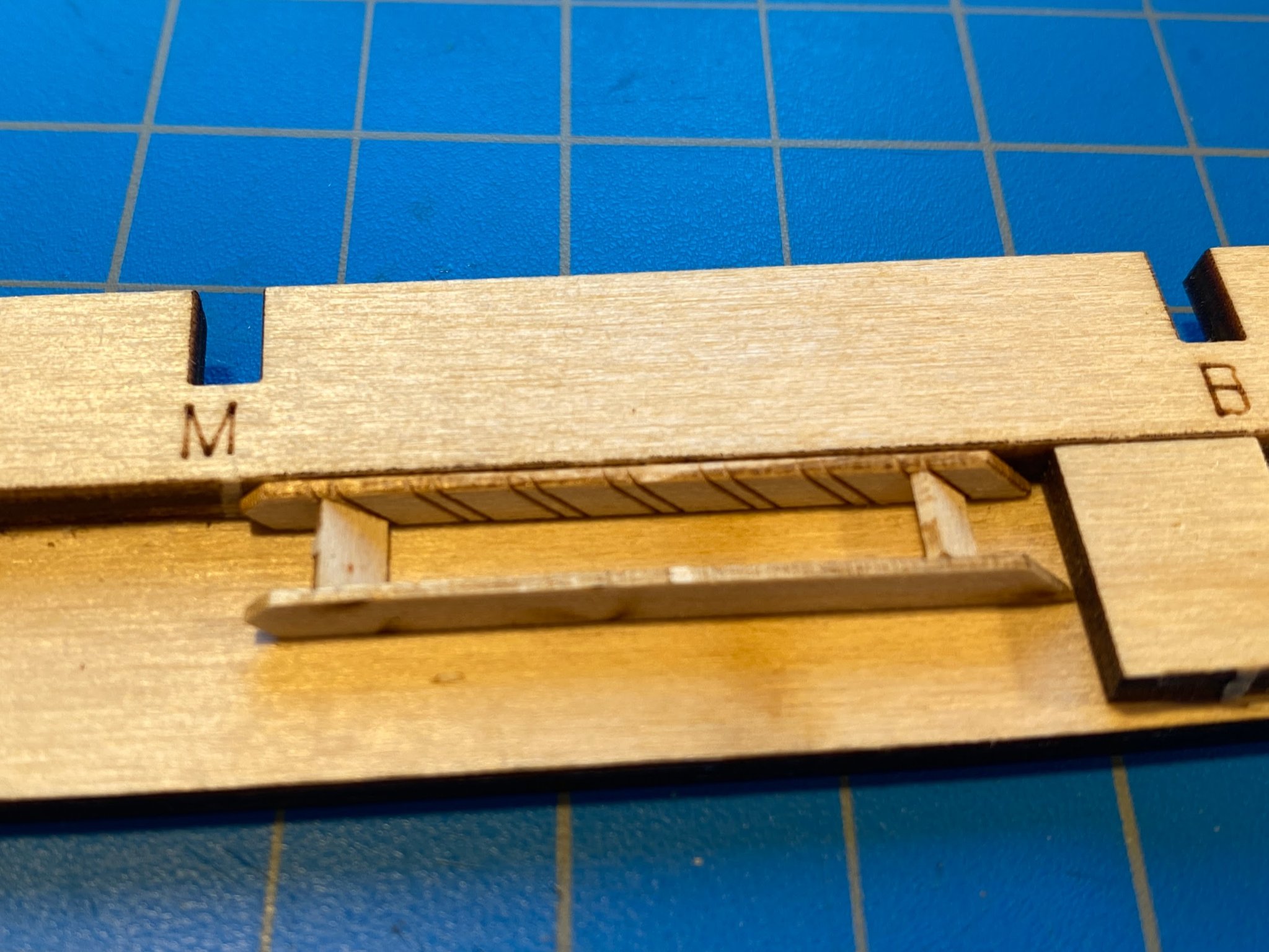
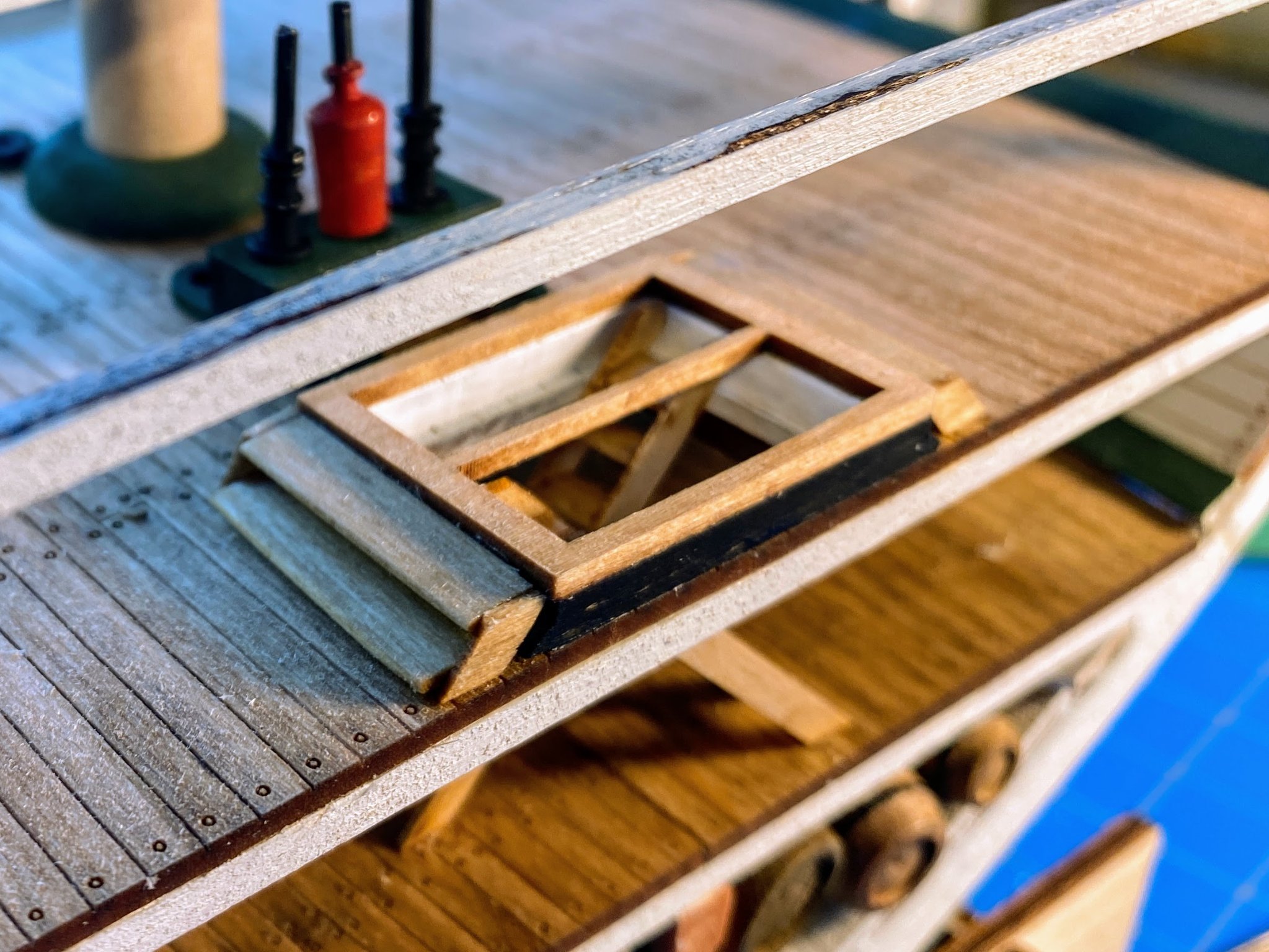
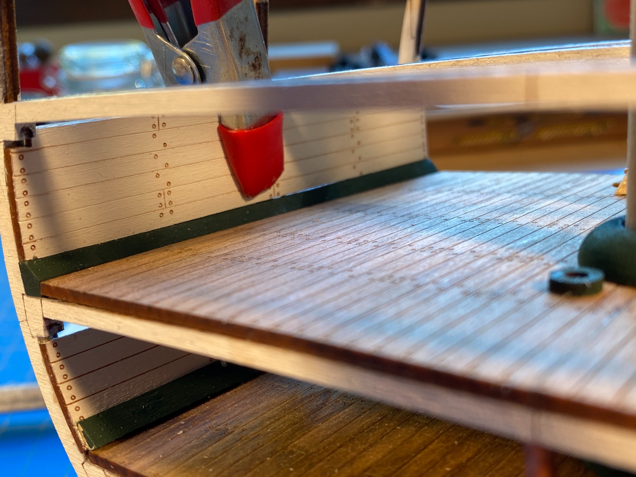
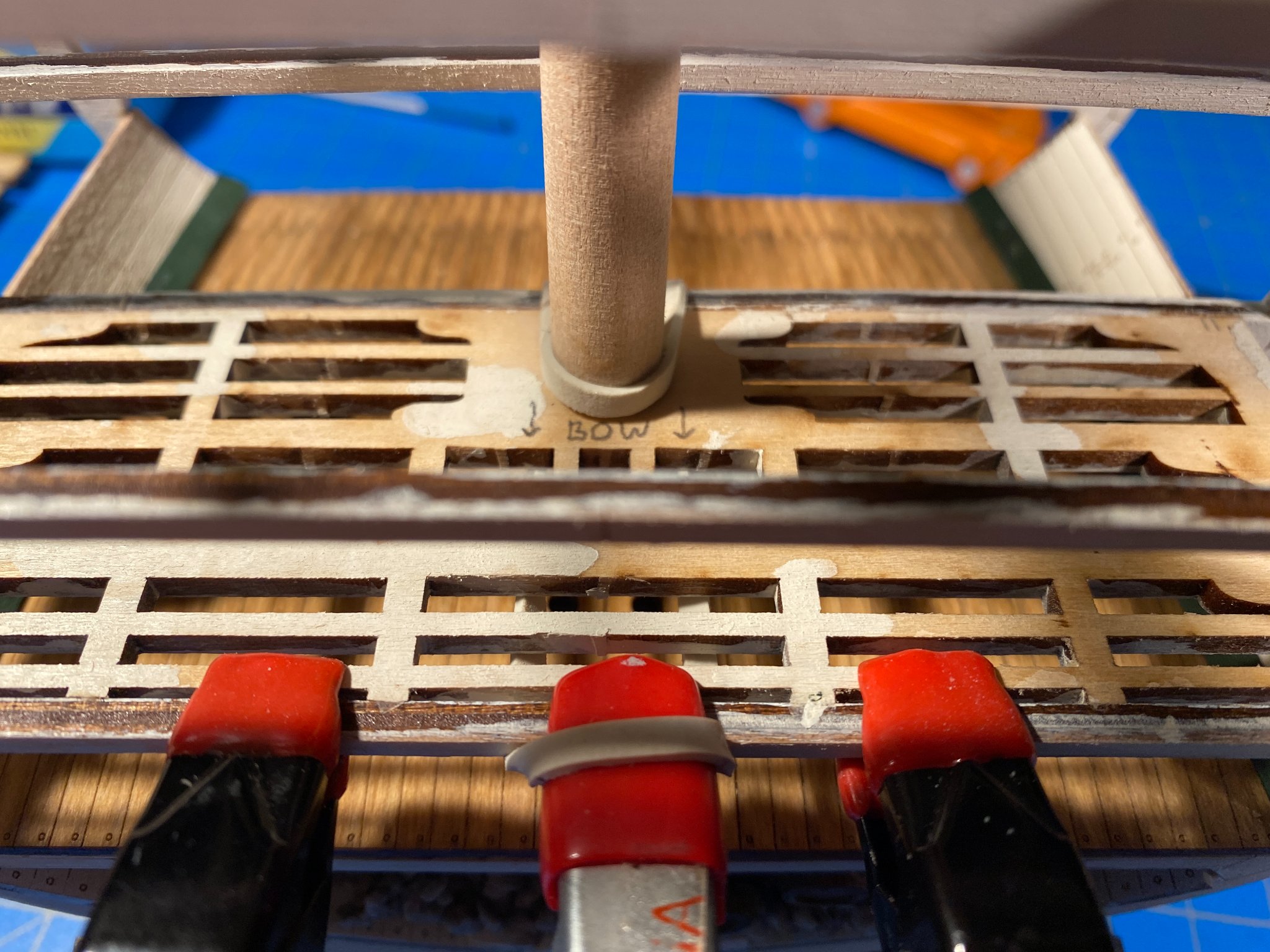
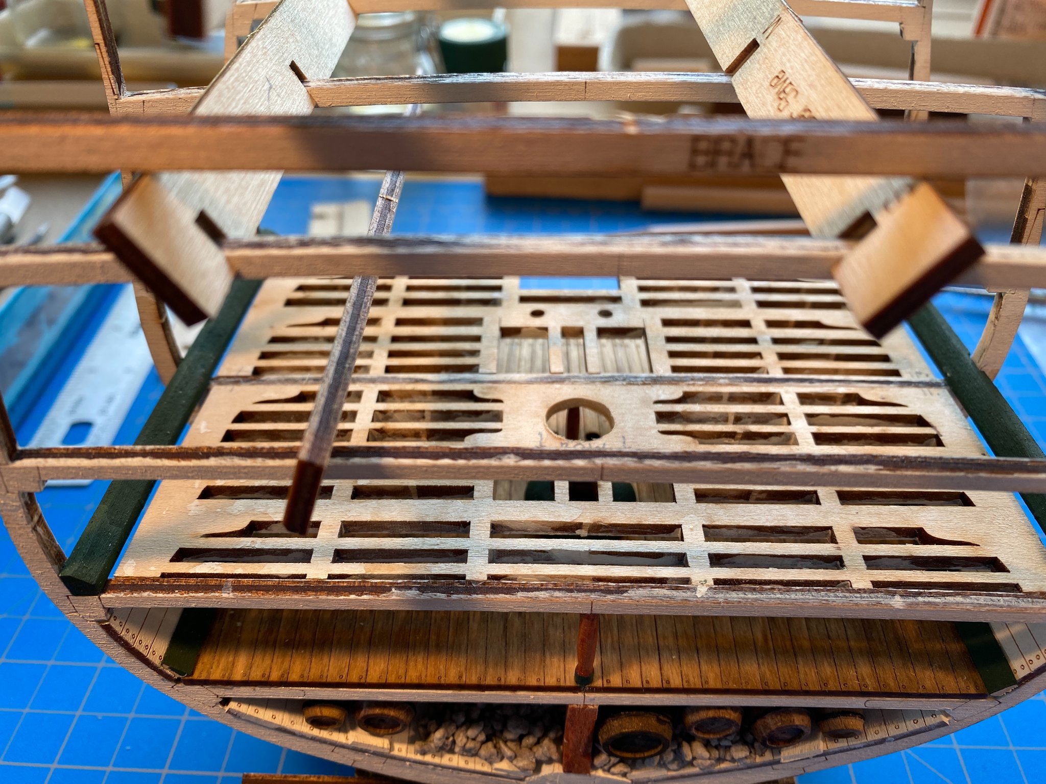
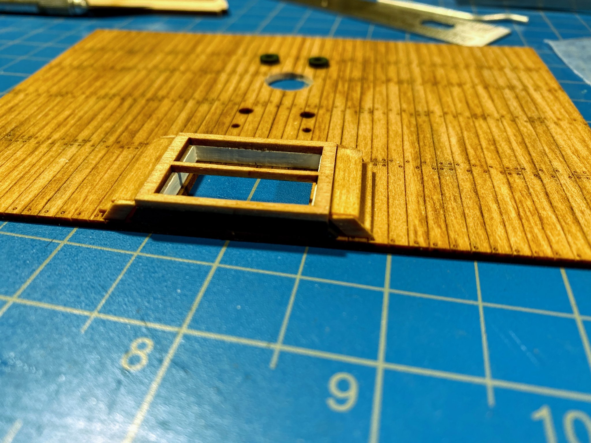
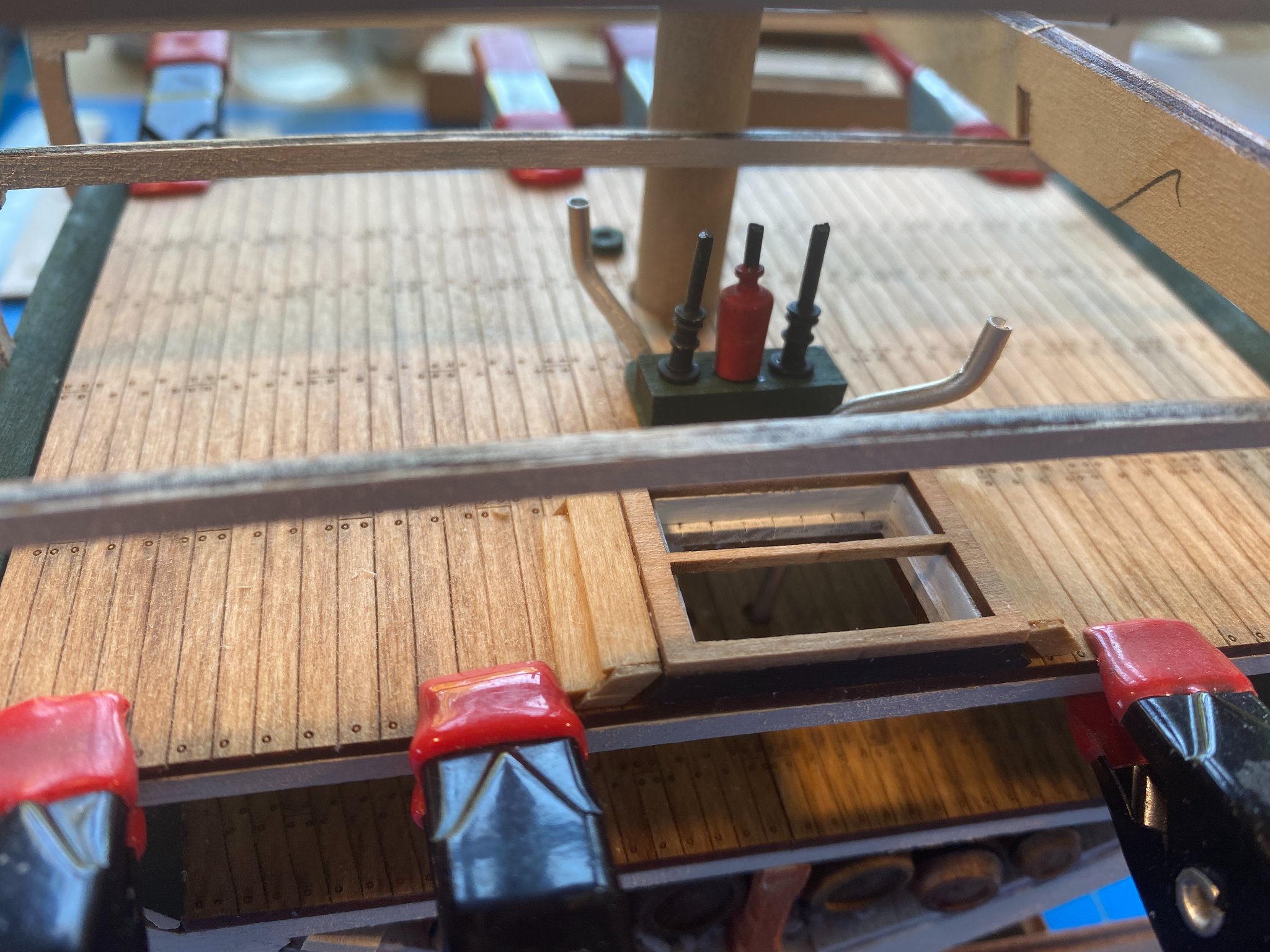
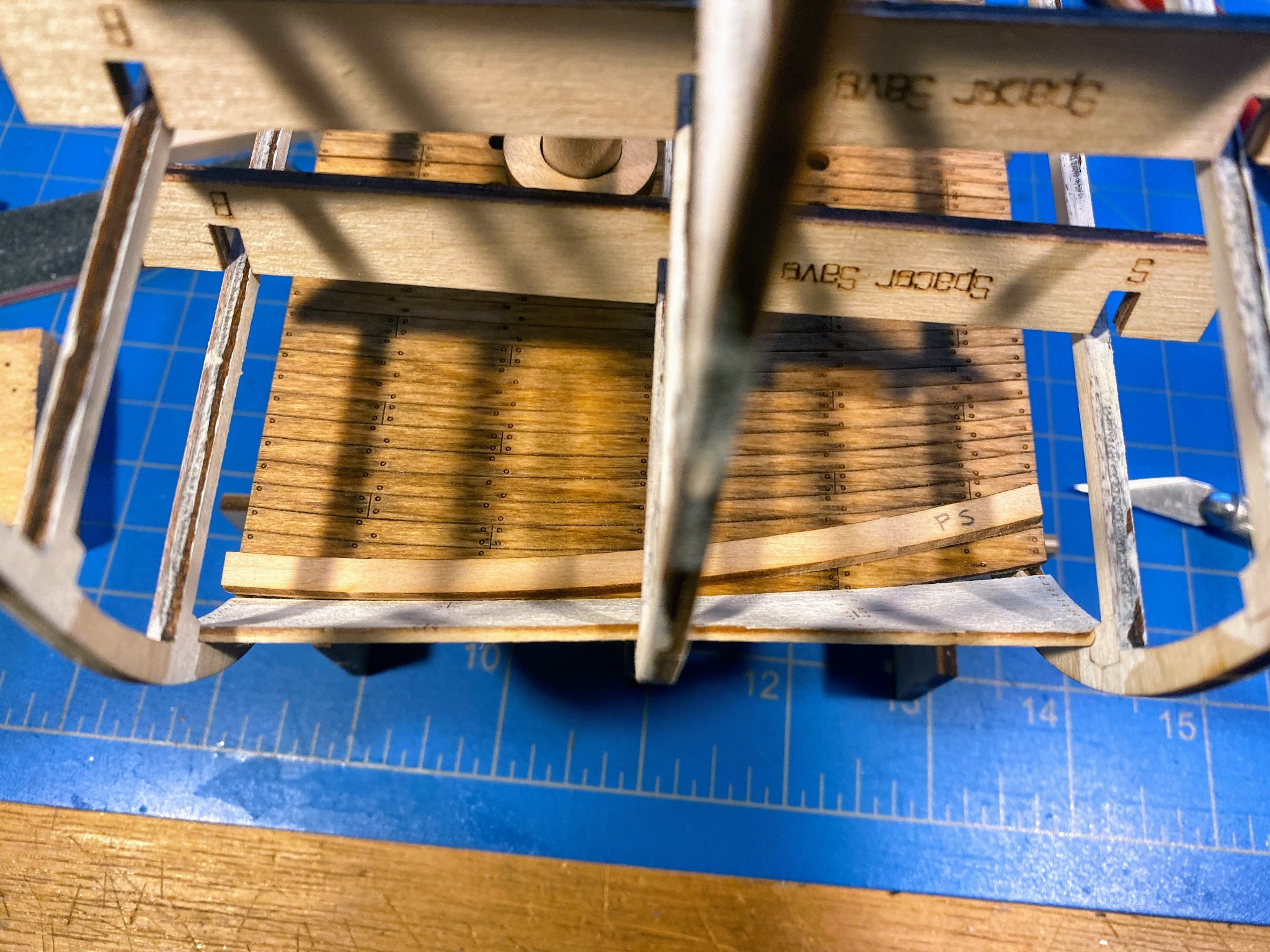
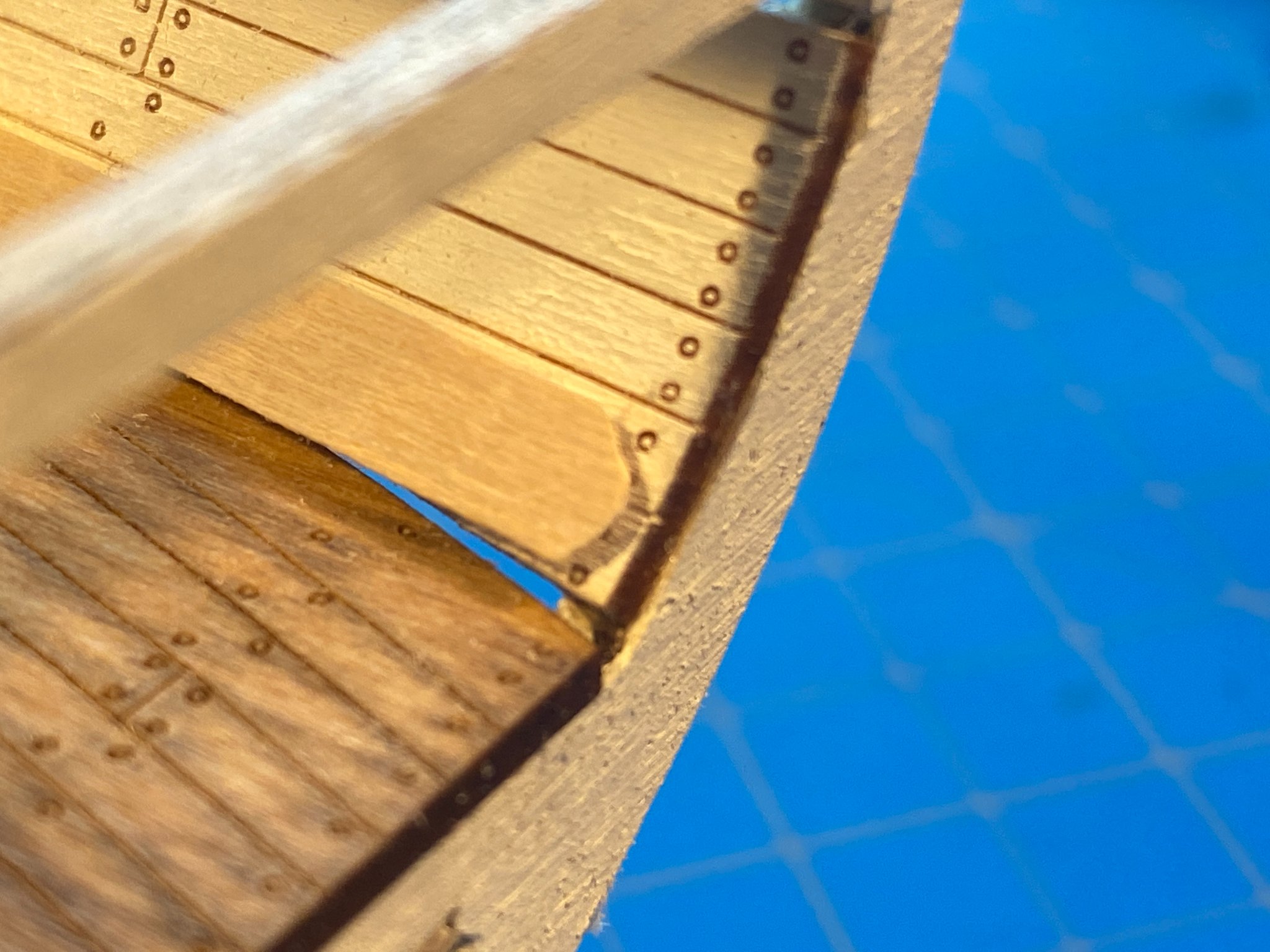
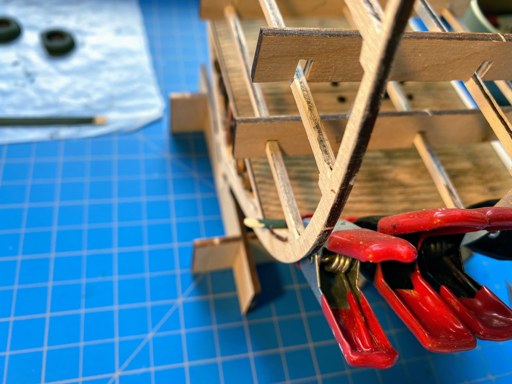
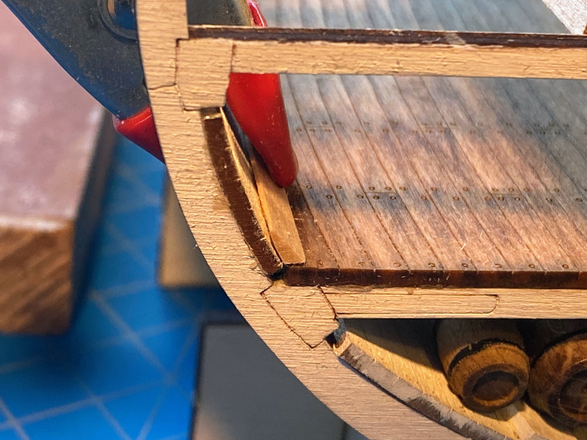
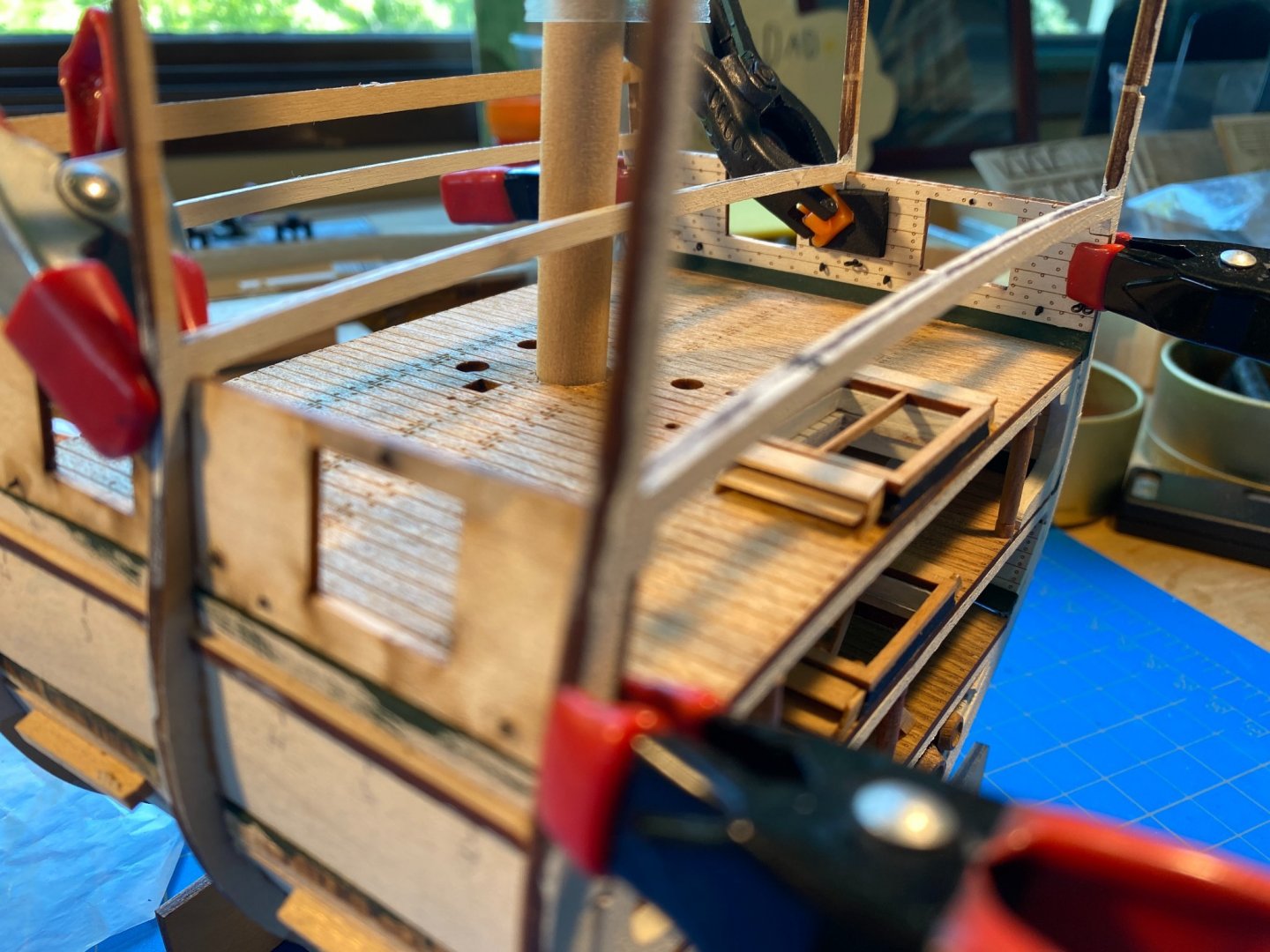
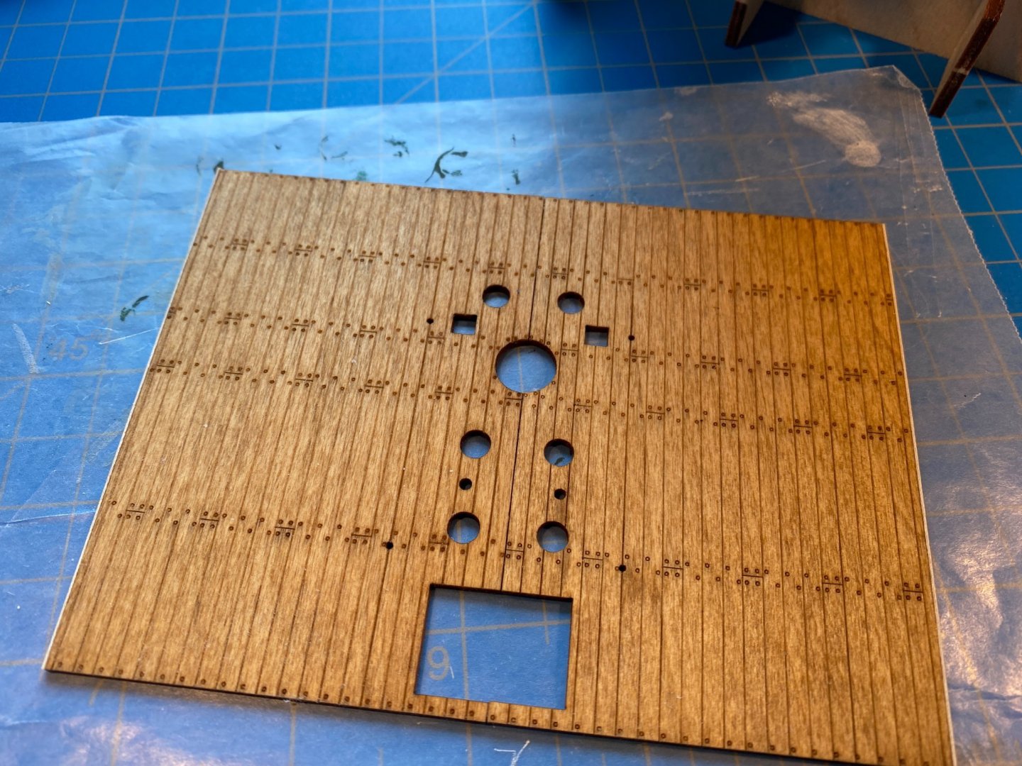
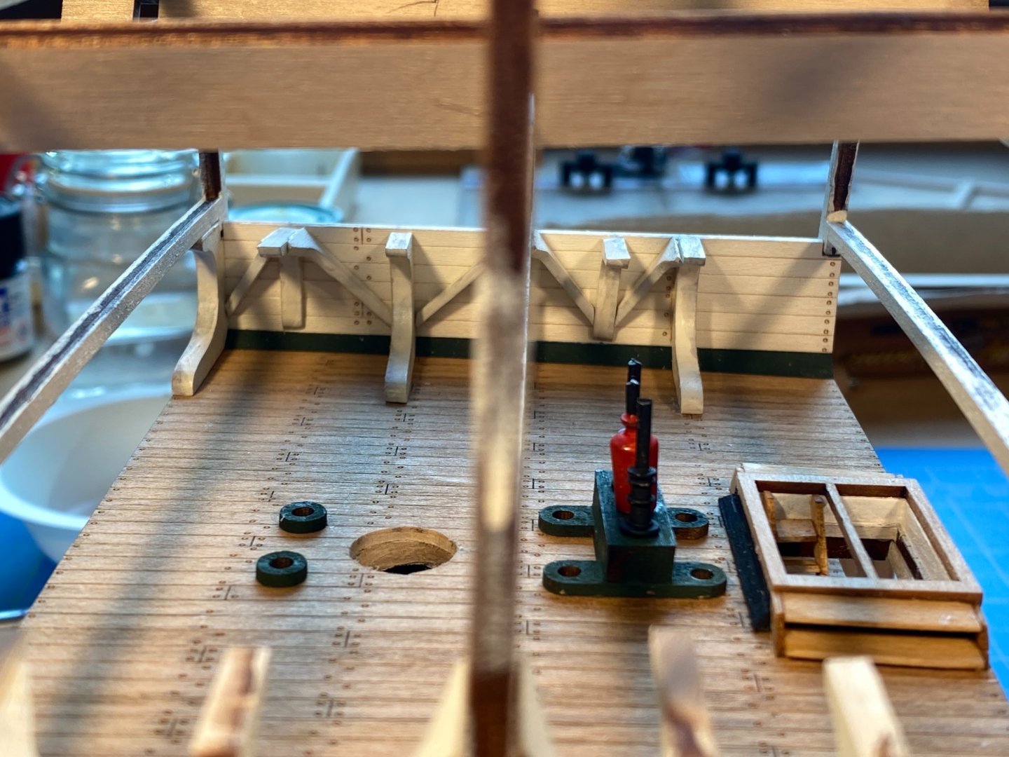
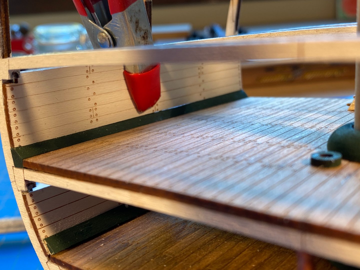
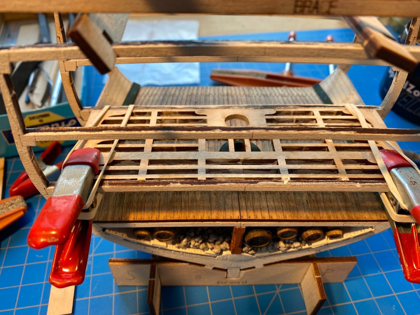
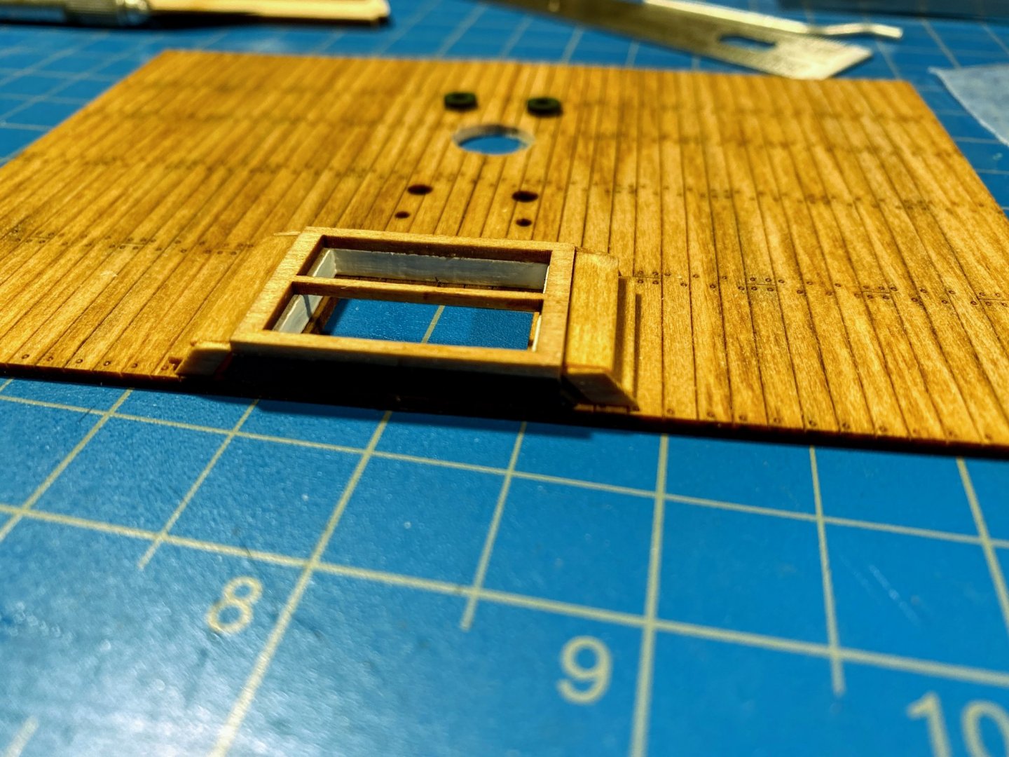
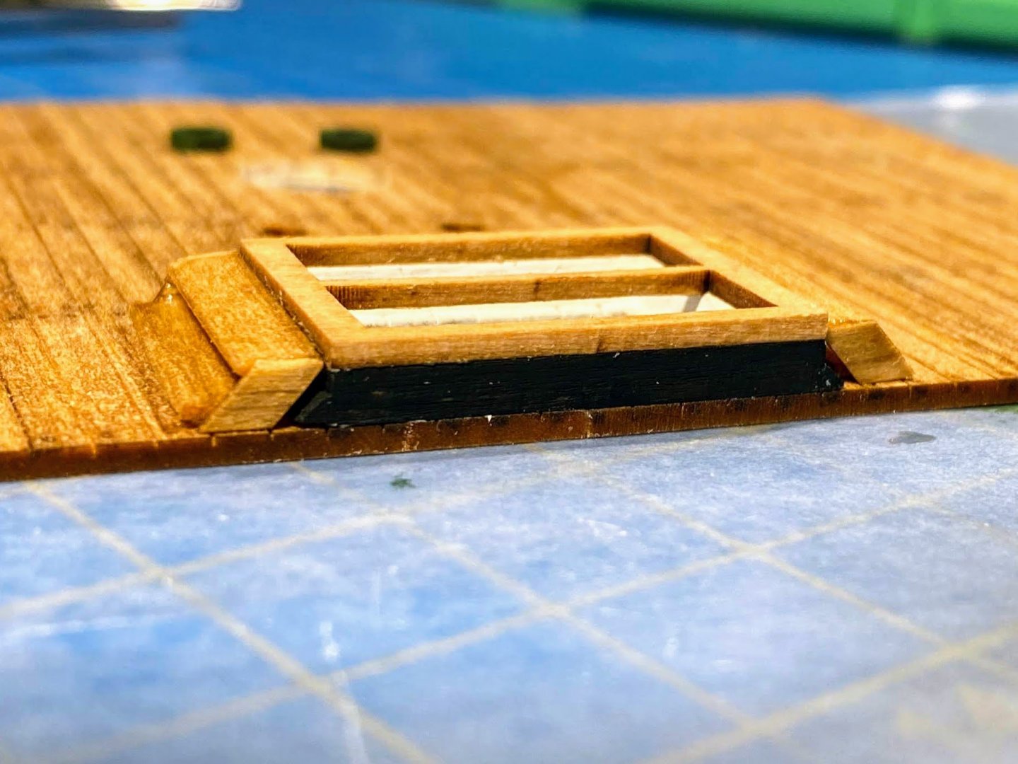
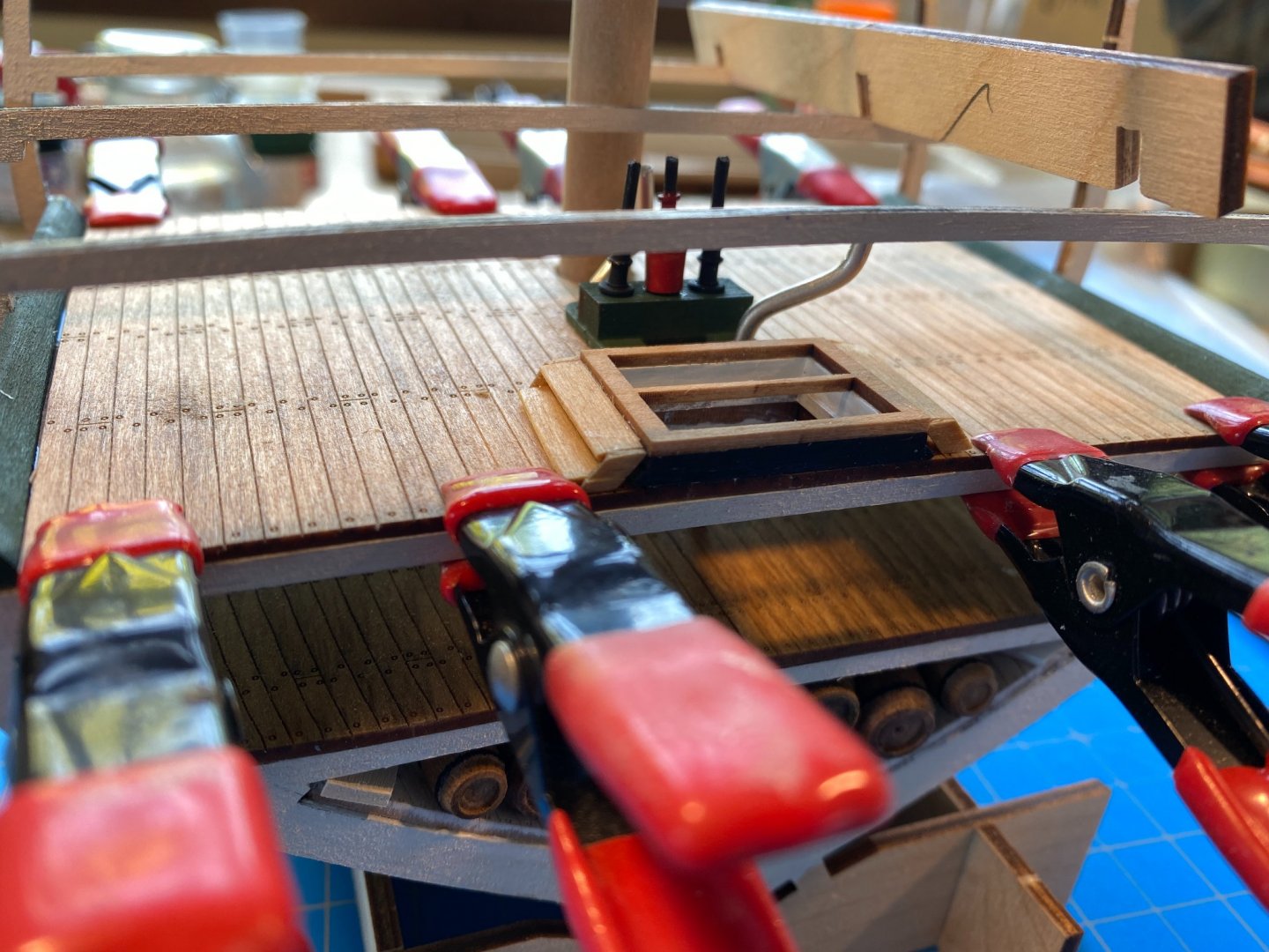
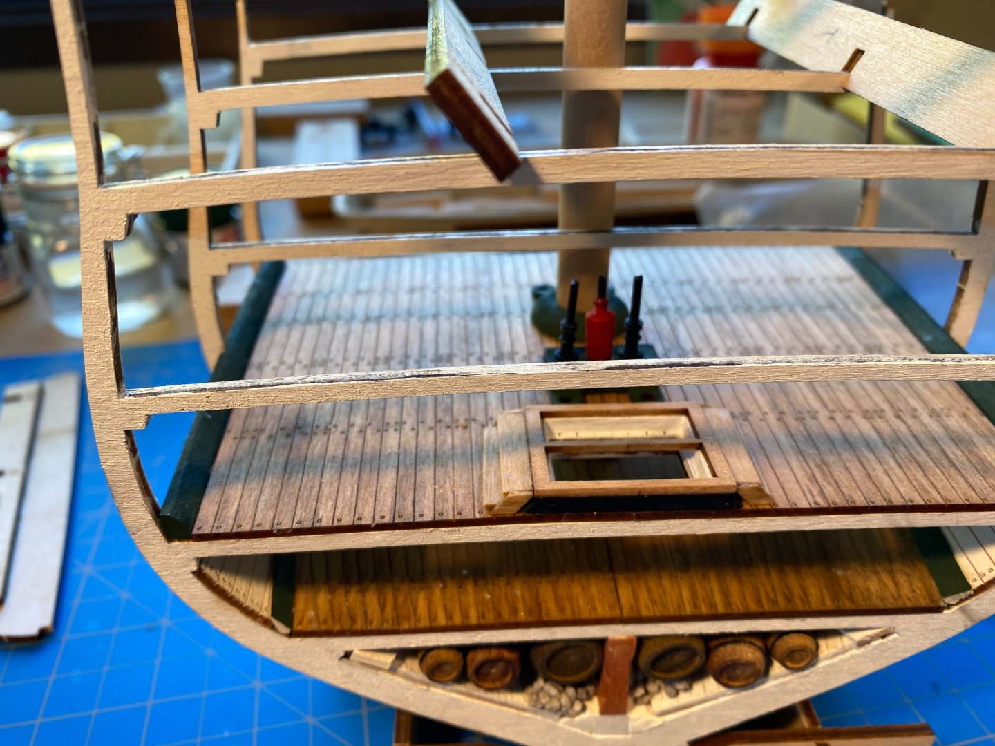
Since my post a couple of weeks ago, most of what I have done has been to do for the gun deck what I did before for the berthing deck -- paint and glue the framing; shape, paint green and glue the waterways; stain, glue together, trim and glue the deck planking in place; and assemble, paint and stain, and glue the hatchway framing in place. The deck planking had some surprises . . . there was a small gap between it and the waterways, so I glued a 1/32” strip to each side of the planking. That done, I found I had to do a little bit of sanding at one end of one side, and I still had a bit of a gap on both sides of the other end. I painted a narrow strip of black on the framing adjacent to the waterway to make those gaps a little less obvious and decided that would be good enough. The picture with the clamps below is pre-glue and pre-black paint. A couple of things are worth mentioning regarding the hatchway steps. First, the steps come in two lengths. The longer one is supposed to be glued on top of the risers, and the shorter one glued between the risers, as one of the photo captions in the instructions clearly says. I overlooked that when doing the berthing deck steps, glued both steps between the risers, and the end result looks a little sloppy as a result. I might someday redo those steps. Second, I mentioned previously that the risers are marked to show the location of the lower step, but the mark is laser cut almost all the way through the riser. I broke two risers trying to assemble the steps and a third one trying to glue the assembled steps in place. Next time around I think I will leave the laser cut risers alone and simply cut some appropriately sized trapezoid pieces from a 1/32” strip. I mentioned earlier in the build that the instructions refer to eight poles on the berthing deck (two on the centerline and three on each side closer to the knees), and the accompanying photo shows the same thing. But the plans show an additional pole on the centerline, somewhat aft of the forward pole, and later photos in the instructions show the additional pole. So I shaped another pole and glued it in place (with some difficulty) after the gun deck framing was glued in; without the framing there is nothing above to glue the pole to. Gluing it in place would have been easier if I had not installed the forward pole until after gluing this additional pole in place. Meanwhile I had painted the pump assemblies and the round flanges that get slid onto them below the gun deck, and cut them to the right length so they would fit nicely into the green berthing deck flanges and the flanges that are part of the green pump assembly on that deck. In the photos below they are dry fitted in place, without the additional flanges. Looking ahead at rigging the long guns, I decided that the fewer things in the way on the gun deck at that stage the better. The pumps can be glued in place after the long guns are rigged. And I think I’ll wait to install the berthing-deck- to-gun-deck ladders until after the pumps are glued in. I have painted the gun deck sidewalls white. Next steps are to glue those in place, install some knees, then get to work on those cannons.


- 163 replies
-
- 3
-
-
- Model Shipways
- Constitution
- (and 2 more)
-
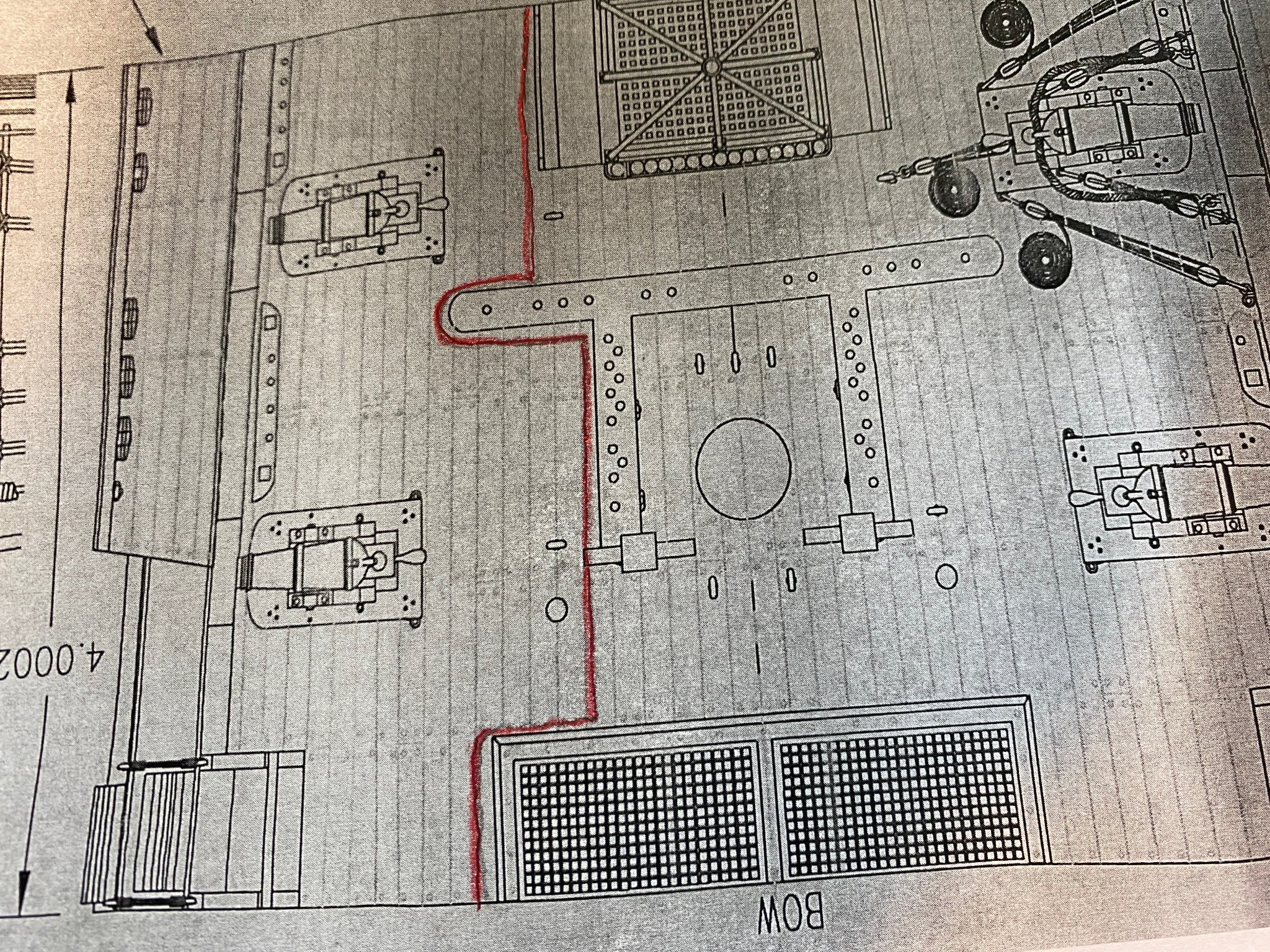
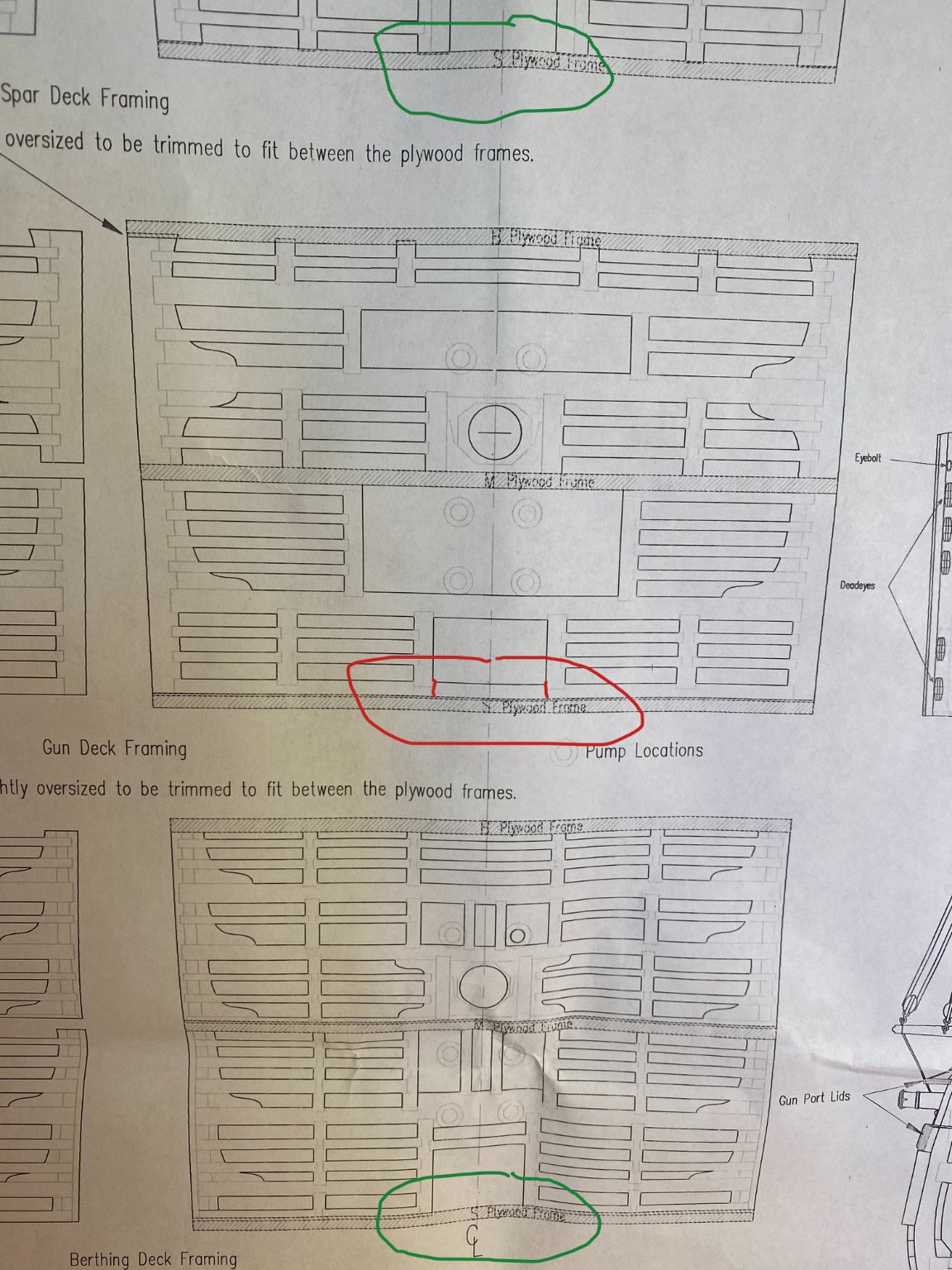
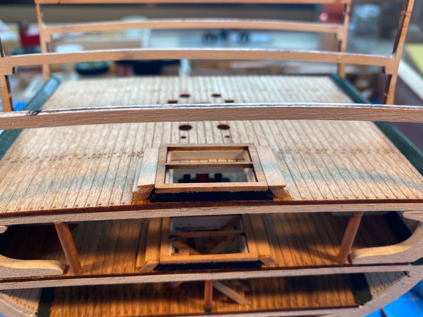
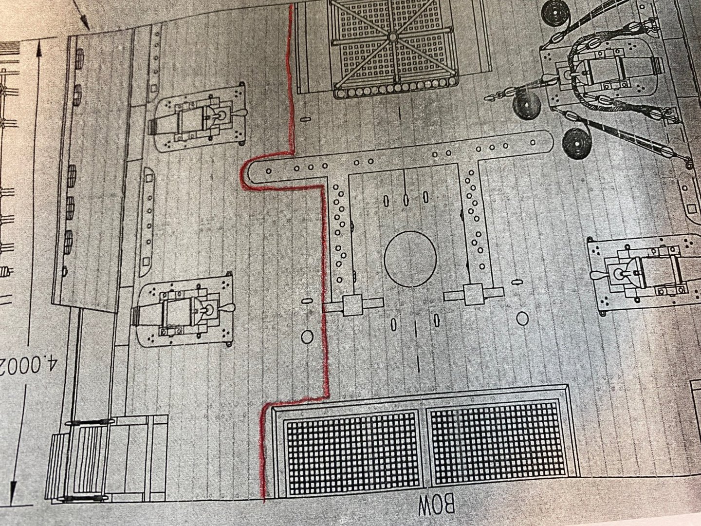
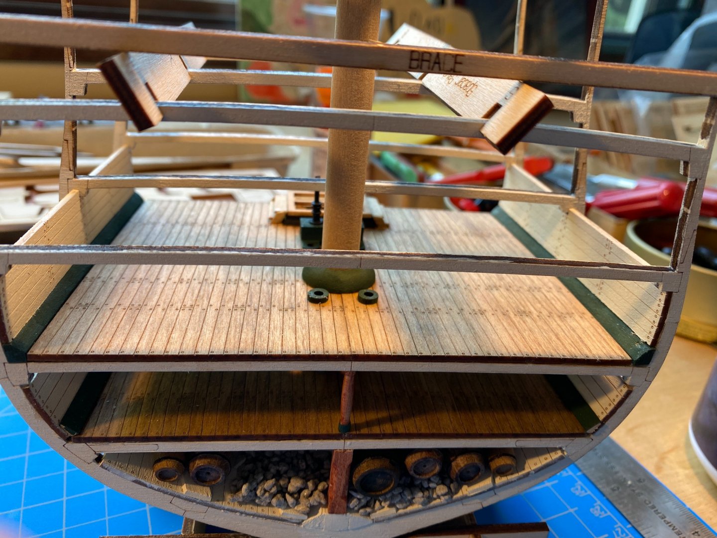
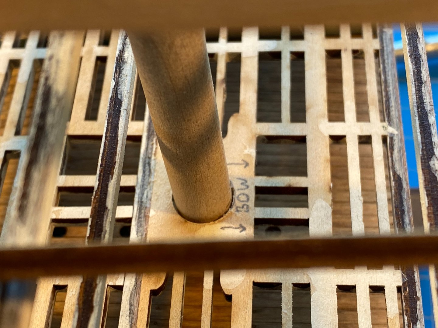
Hi Gary, your tips and advice are always greatly appreciated. Keep them coming! I'm not sure why I suggested that I might not glue the mast surrounds in place. As I have mentioned before, I have enlarged the mast hole in every deck framing and planking piece so that the mast can be moved just a bit when it comes time to determine vertical alignment and rake. I don't expect to do that until the hull is complete and I'm working with the full length lower mast. Then when I'm satisfied that the mast alignment is right, I will glue the mast surrounds to their respective decks, eliminating any wiggle room and holding the mast firmly in place. I'm still thinking about the spar deck planking. If I leave one side off, I won't install the carronades on that side. I might also cut away some of the deck framing, trying to do it in a way that the complete framing can be visualized but not seen. I would also try to cut the planking piece in such a way that it is under the hatchways, the mast surround and the fife rail stanchions but otherwise is cut back to near the centerline, along the lines of the picture below. But with all of that, will there be enough detail visible below to make it worth all the effort? I too will be interested to see what I decide to do. 😊
- 163 replies
-
- 2
-
-
- Model Shipways
- Constitution
- (and 2 more)
-
Very nice work HakeZou. It appears that OcCre makes the kind of kits designed to make very attractive models that do not necessarily accurately reflect the real ship (e.g. interesting exotic woods, brass fittings [such as anchor chain] left bare that would never be brass on the ship, etc. ) Nothing wrong with that style if it suits your fancy, and it is what my Artesania Latina Bluenose build was. But when I get around to doing my Endurance build, I'm thinking I will probably want to do a more accurate depiction of the real ship, meaning that almost everything will be painted. If that is the case, is there any real reason to put on a veneer planking? I'm thinking that bare walls of the main cabin, that will eventually be painted, will be just fine. Or am I missing something? You should get more reliable answers than I can give you on this, but I always assumed that varnish was a kind of finish, and that satin varnish is simply a kind of satin finish. Let us know if you learn something different. I always look forward to your next installment.
-
Something else . . . I have not glued any of the mast surrounds in place. My thinking is that I can loose fit them in place as I slide the real mast through all the decks the final time, after I'm comfortable with the rake and vertical alignment of the mast. Once the mast is in place, I might at that time use tweezers to slide each surround up an inch, add a drop of glue to the bottom, then let it slide back down to the deck. Or maybe I won't glue them at all. After all, once the mast installation is final, the surrounds aren't going anywhere.
- 163 replies
-
- 3
-
-
- Model Shipways
- Constitution
- (and 2 more)
-
I am still thinking about Tim's ("Schooner") suggestion to leave half of the deck planking off to reveal detail on the deck below. My thinking now is to install all of the gun deck planking, then do the half plank only on the spar deck, since most of the below decks detail is on the gun deck. No final decision yet though.
- 163 replies
-
- 1
-
-
- Model Shipways
- Constitution
- (and 2 more)
-
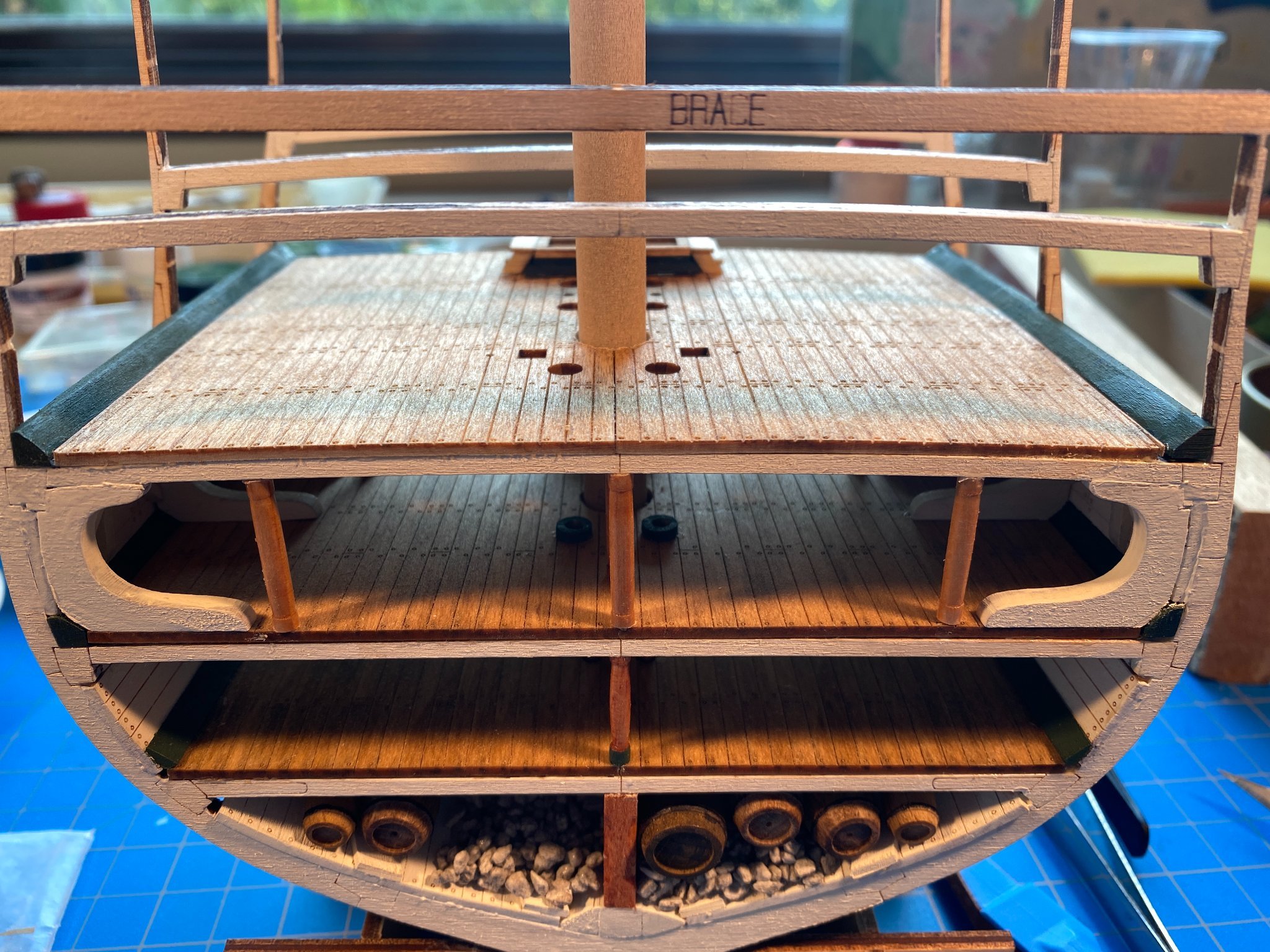
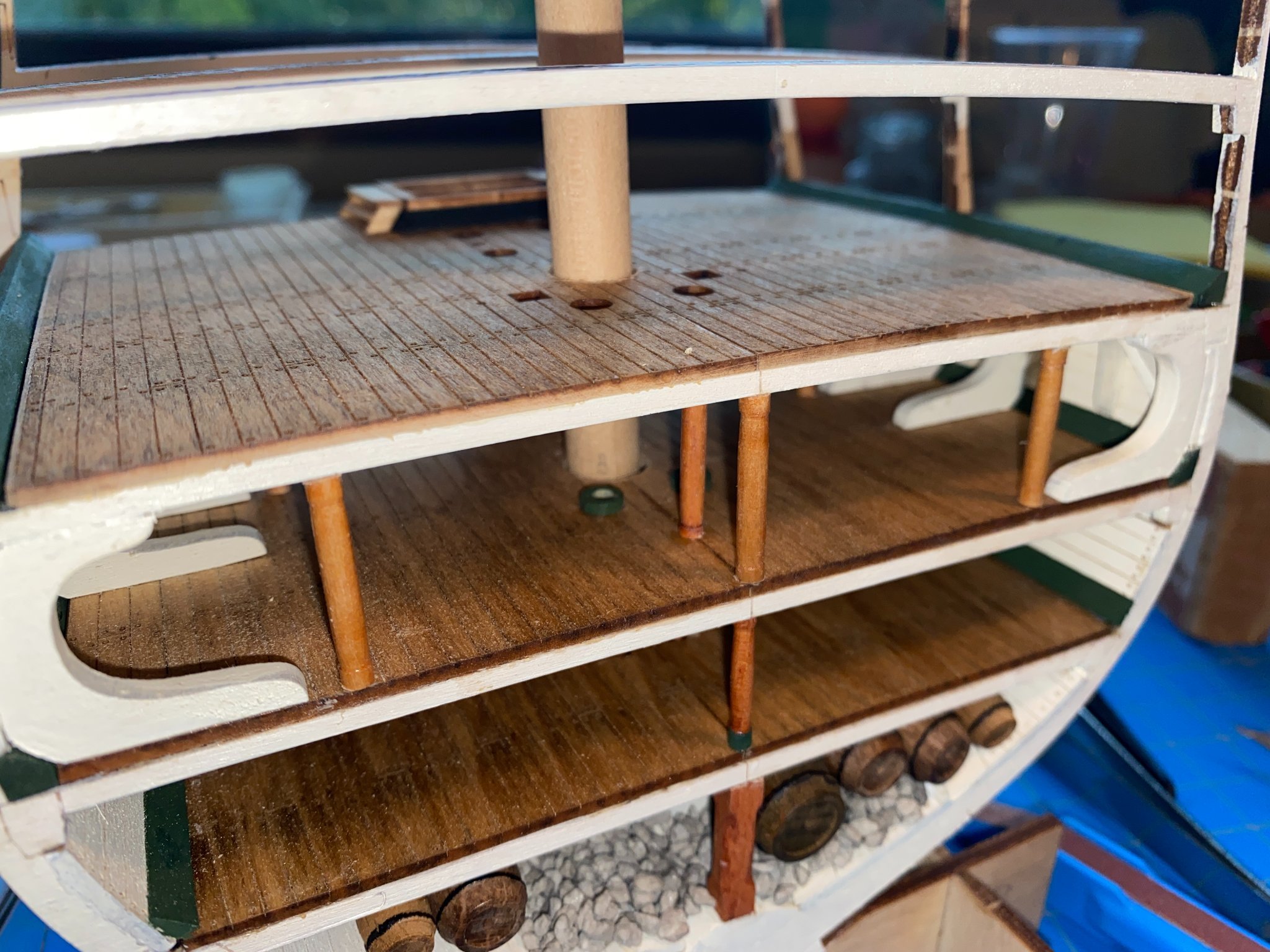
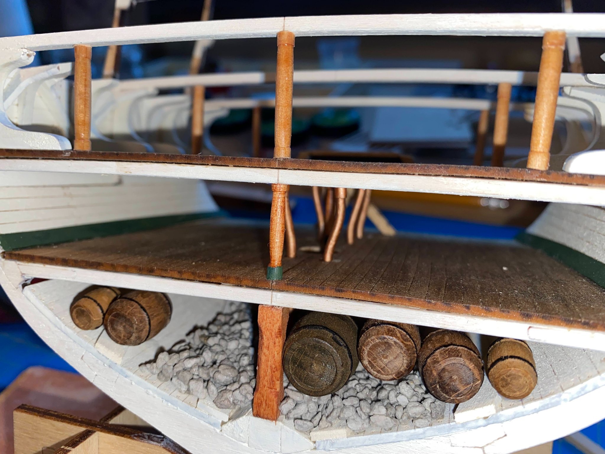
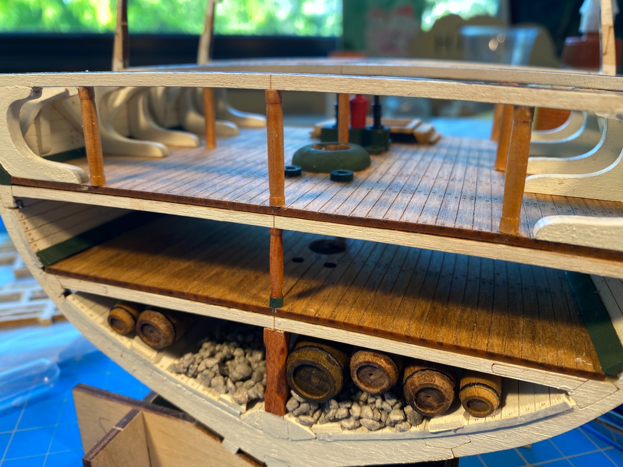
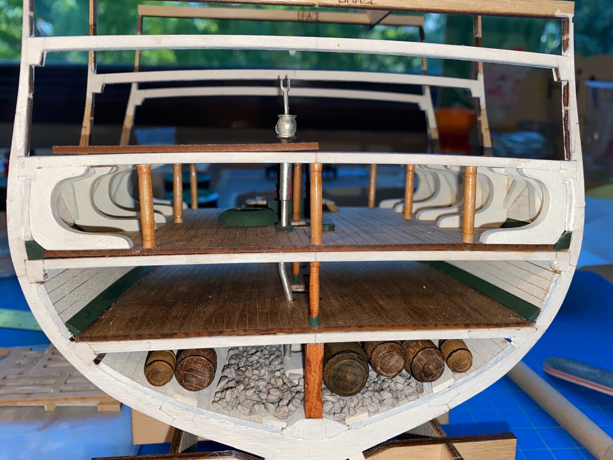
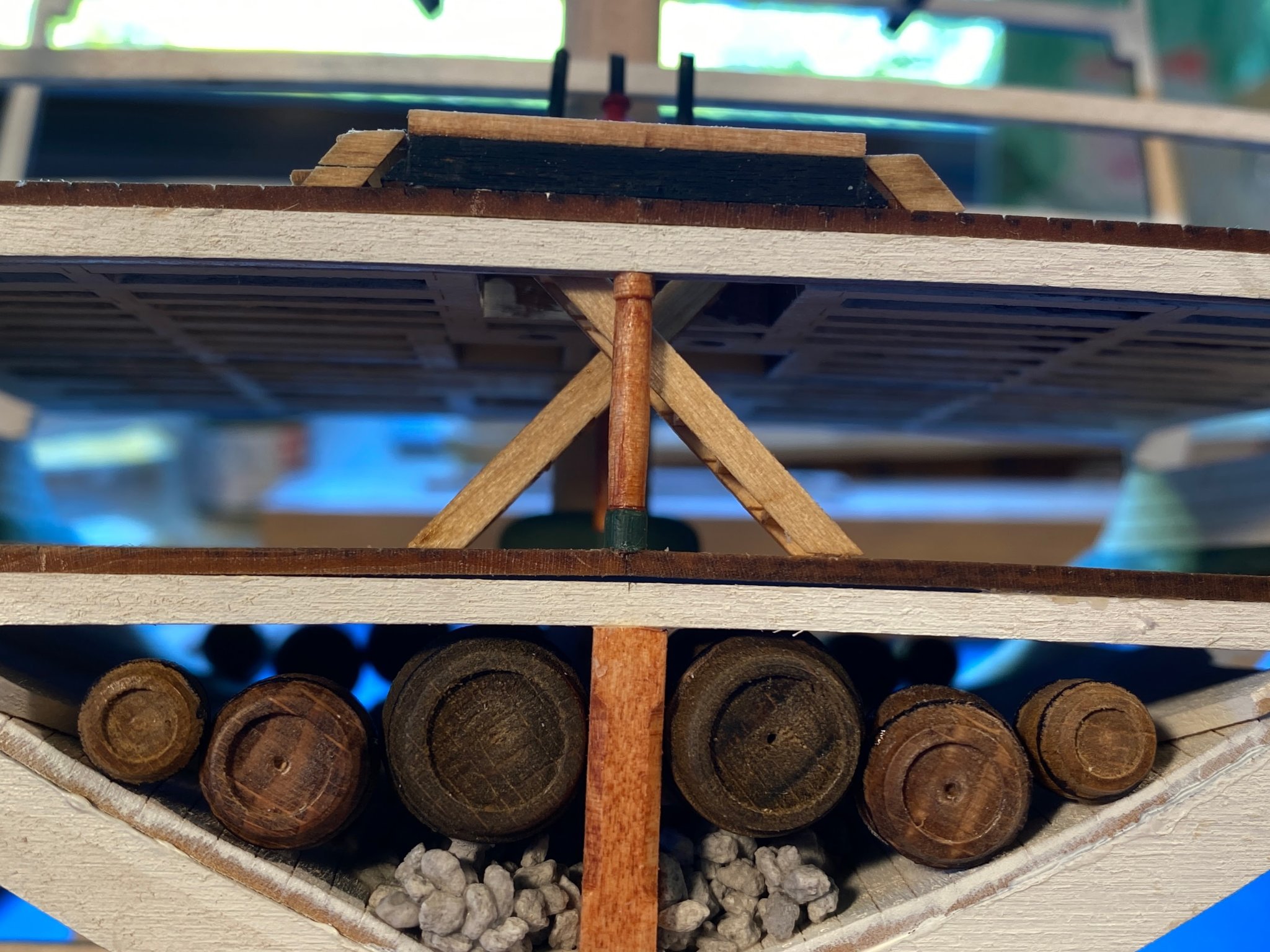
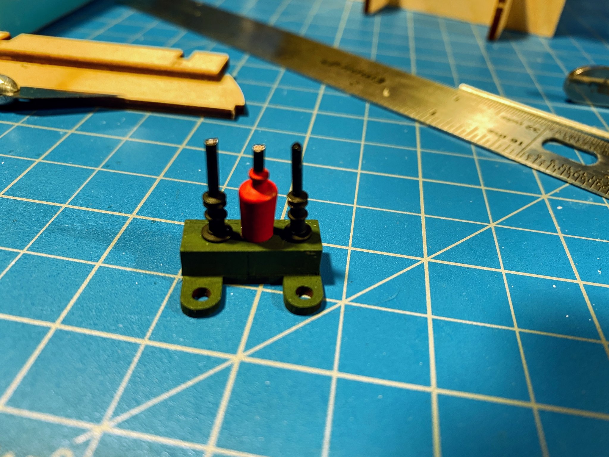
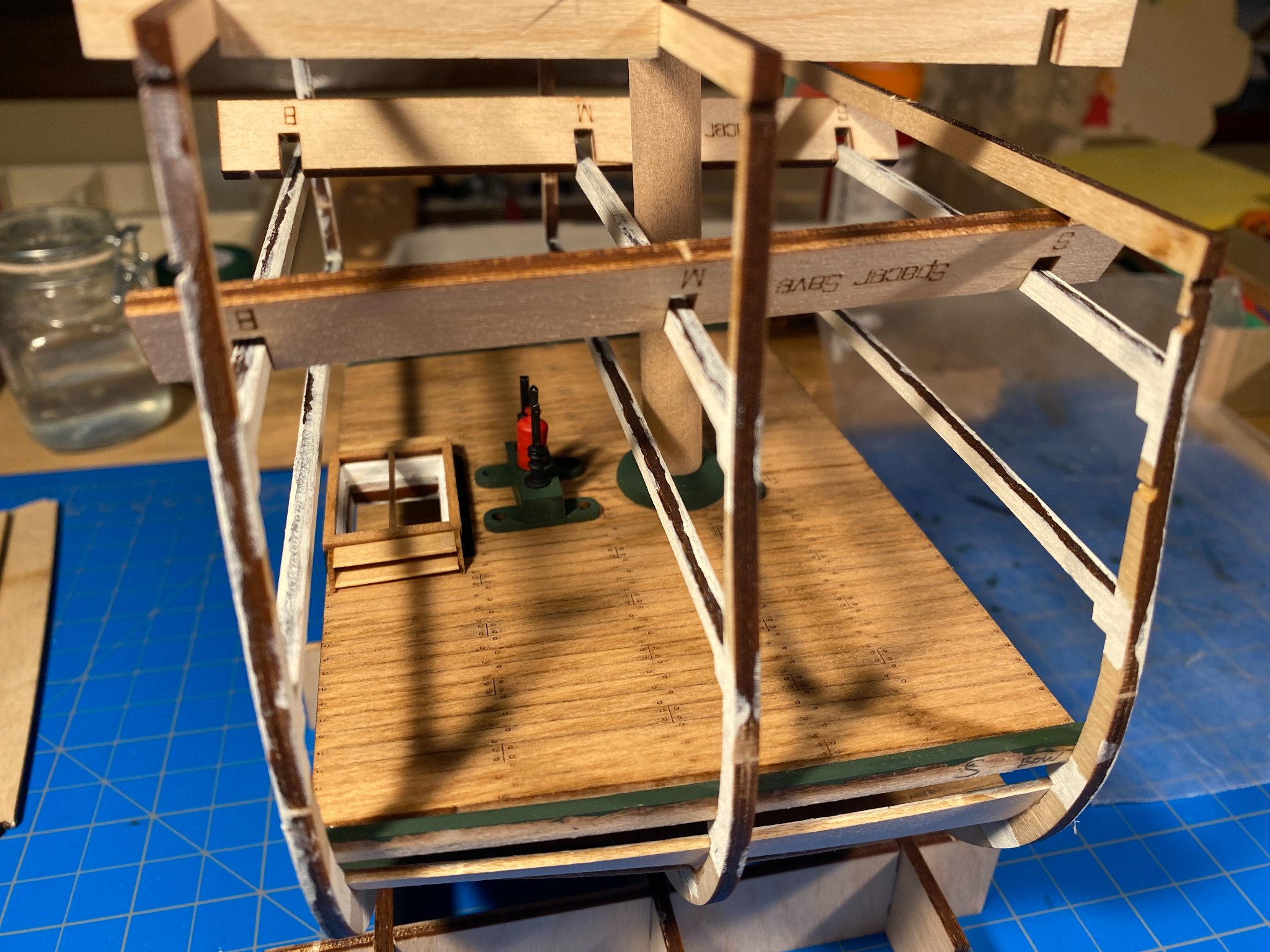
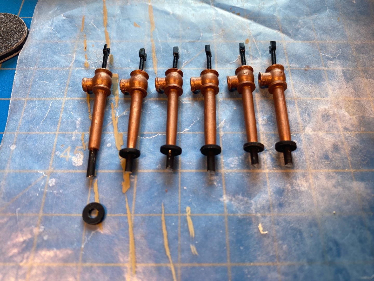
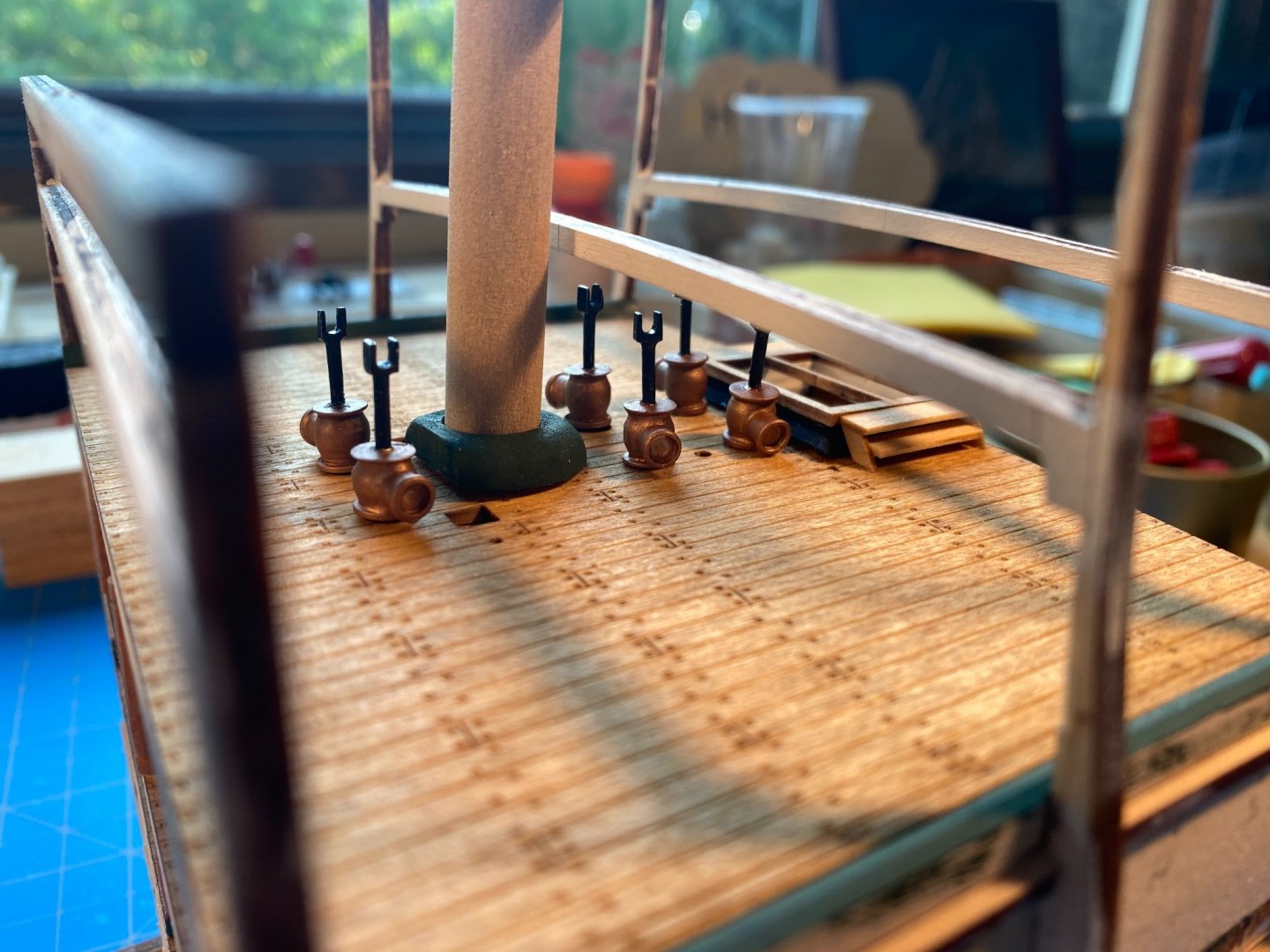
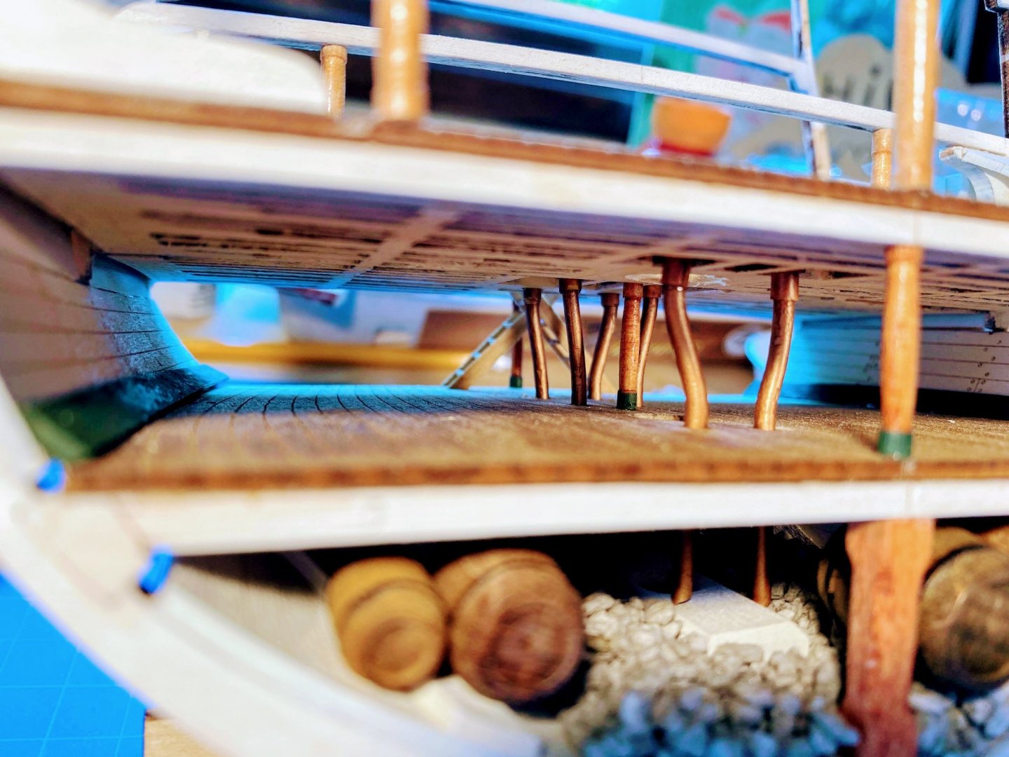
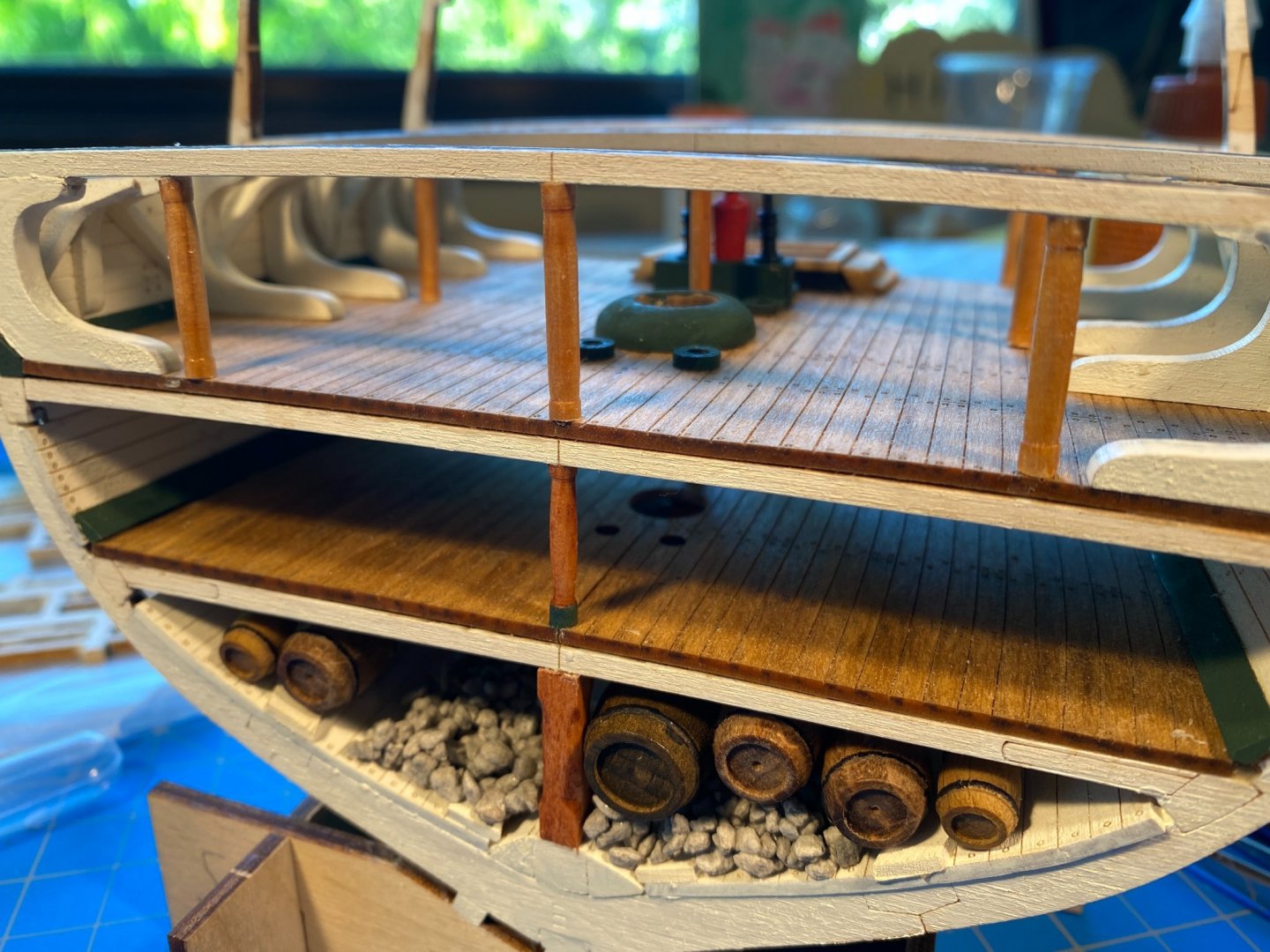
Bilge pump pipes . . . As mentioned in my last post, I ran into problems getting the pipes to bend sufficiently to end in the gravel but not so much that they could not be passed through the holes in the decks. In the process I accidentally popped off both green flanges over the forward holes. Having the flanges out of the picture made things quite a bit easier. I therefor intentionally pried off the pump assembly, because its flanges were also causing problems. Cutting and shaping the pipes was a lot easier if they only had to pass through the decks and not the flanges too. In the process I decided that getting the pipes into the gravel, instead of ending on top of the mast step and keelson, was more than I cared to tackle. I had ordered some copper paint from Model Expo. What arrived was not at all what I would call copper. Looks more like metallic maroon to me. Fortunately I had some copper paint I used a few years ago for the hull of my yacht America build, and when I opened the container I was delighted to find that it hadn’t dried up. I think I used something from Model Masters called dark copper, to which I added something to make it even a little darker (flat black??) but I don’t remember. In any event, it was a lot better than what I got from Model Expo. I cut the pipes so they would just reach the holes in the berthing deck. Those holes are quite a bit larger than the pipes, so I wrapped some masking tape around the top of each pipe to fill the gap. Once in place I put a drop or so of medium viscosity CA in each hole to keep the pipes in place. In the first picture below you can see one pipe with the masking tape, one with a test painting of the old copper paint I found, and a scrap piece with the Model Expo “copper” paint. The second and third pictures are views of the pipes installed, looking through the orlop deck. Fourth is the tops of the pipes seen in the holes, looking from above the berthing deck. The flanges will work well to receive the ends of the pipe extensions which are part of the pump pieces, assuming they are cut to the right length. Last picture (a little out of focus for some reason) shows the flanges and pump assembly glued back in place, along with the middle post, which I had accidentally dislodged through careless use of long tweezers. I also straightened and reglued the post which is leaning a bit in one of the pictures below. Finally, I went back and edited my post in May describing installation of the berthing deck and suggesting that flanges and pump assembly not be glued onto the deck until this stage in the build. Alternatively, and maybe better, install the pump pipes just after gluing the berthing deck in place.


- 163 replies
-
- 4
-
-
- Model Shipways
- Constitution
- (and 2 more)
-
After writing the above post last night but before posting it a few minutes ago, I found that bending the pipe further made it much more difficult to force it through the hole in the berthing deck, and trying to do so I managed to pop off the green flange on both forward holes. I also noticed that if I lower the pipe enough for the pump to rest on the gun deck as it is supposed to, the top of the pipe ends up well below the berthing deck and there is nothing to glue it to to keep it in place. So I will keep it long enough to glue to the berthing deck, then cut the pipe part of the pump so that the pump itself lies as it is supposed to on the deck above, which will mean cutting it slightly above the pin. That’s OK since I’ll glue the green flange back on the berthing deck and I’ll be able to glue the pump extension to it. Clear as mud? So far I’ve been fitting the pipes through the forward holes. This will be much more difficult when I’m working with the middle and aft pipes, because the ladders and the berthing deck pipe assembly will be in the way. A challenge yet to be addressed . . .
- 163 replies
-
- 3
-
-
- Model Shipways
- Constitution
- (and 2 more)
-
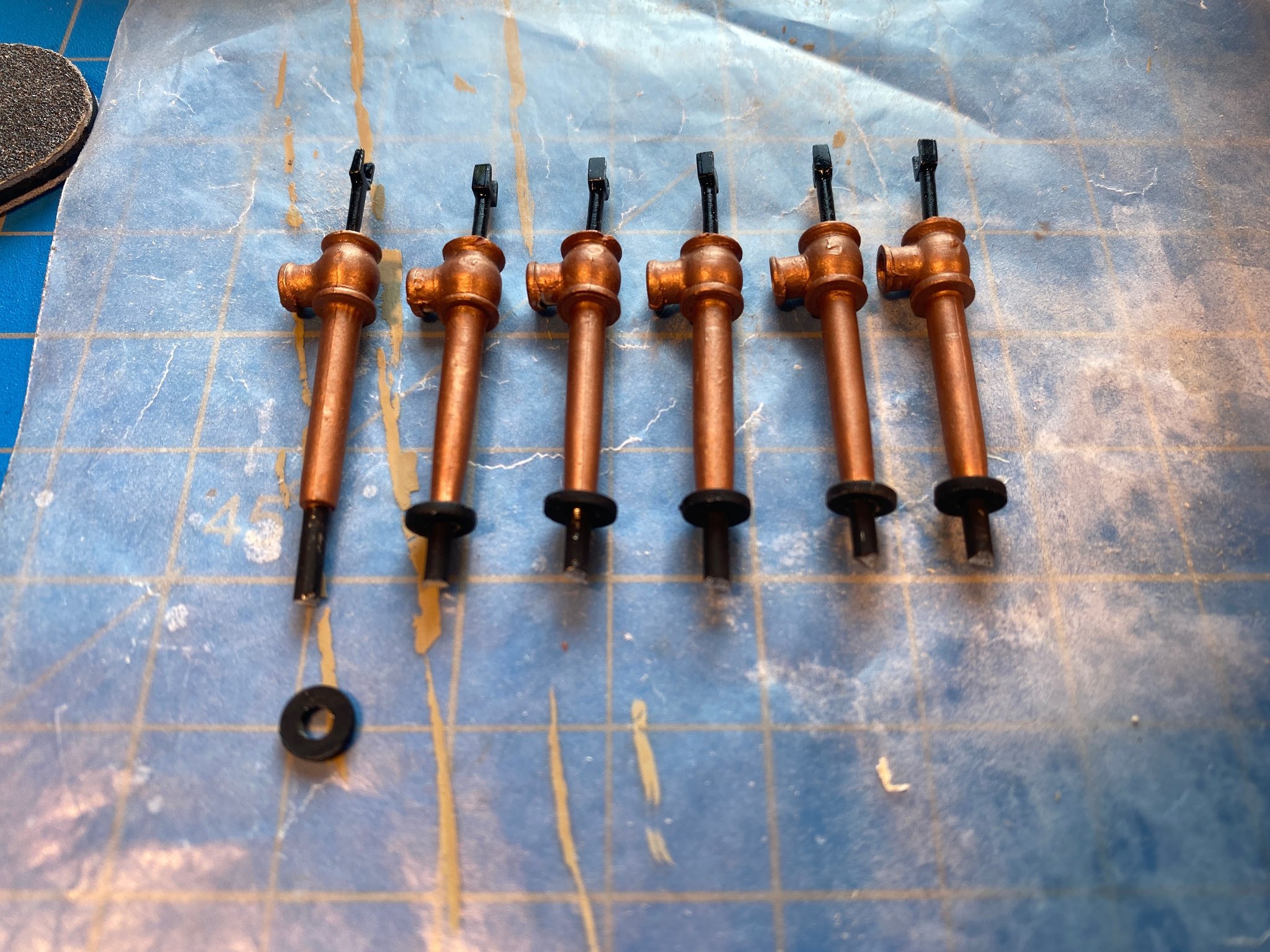
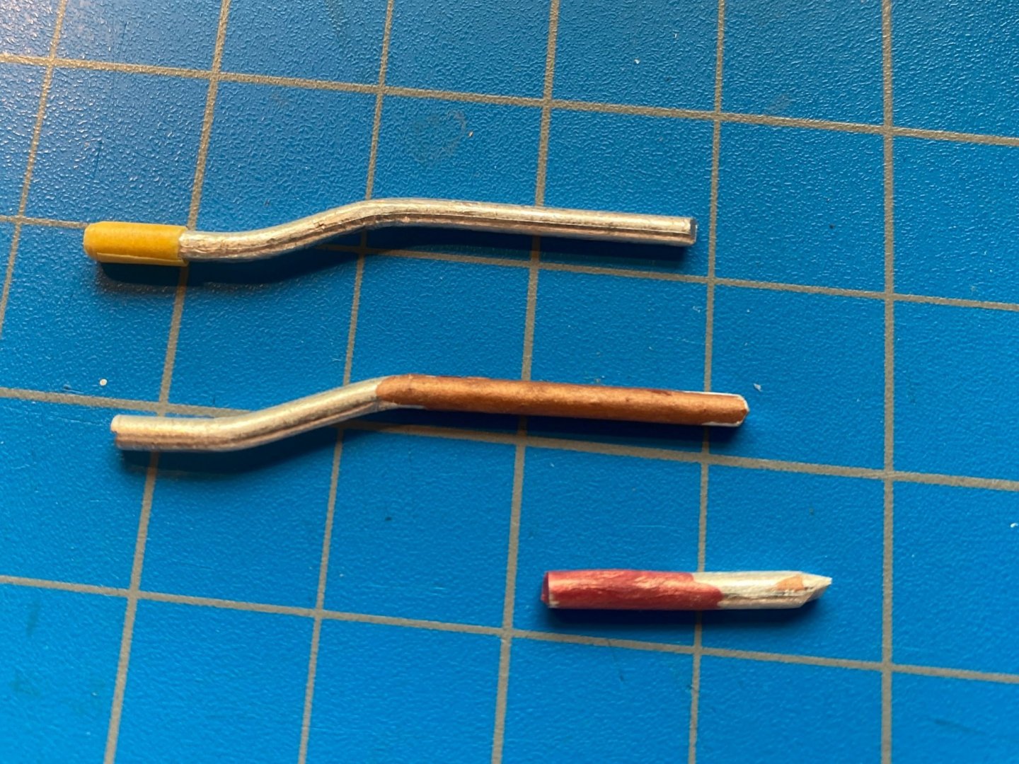
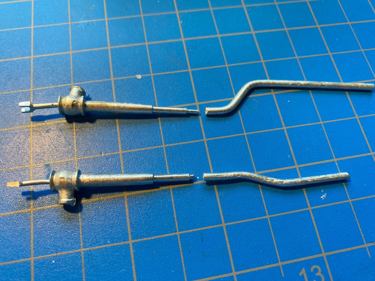
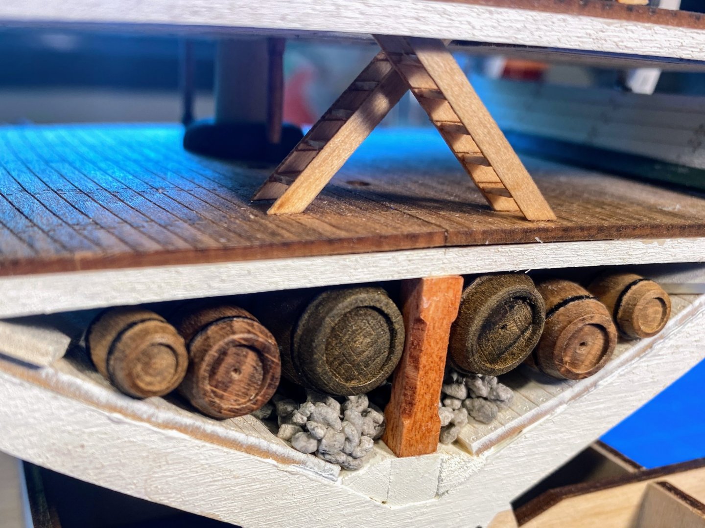
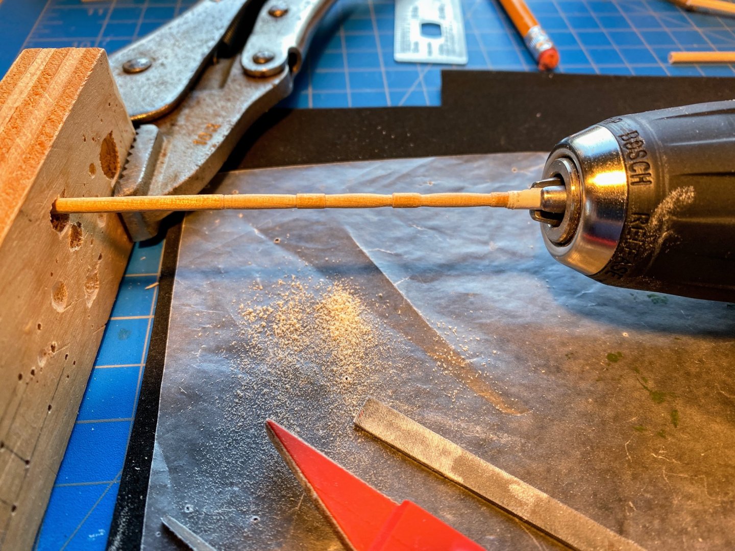
Sometimes life gets in the way of model building, and sometimes life throws a curveball at you, but my absence from the shipyard these past several weeks has all been good -- fun travel, one of the kids visiting, outdoor activities prior to the heatwave, etc -- and for that I am very grateful. I finished installing the knees that help hold up the weight of the gun deck, and shaped and installed 8 posts, which I doubt add any structural support but provide something to hang on to. My homemade lathe (electric drill shown in my posting back the middle of May) worked pretty well, but I found that if my impatience led me to press too hard on the file, the dowel broke. Same thing if I tried to shape more than three at a time. The instructions next have you cut, reshape, paint and dry-fit 6 pump pipes, before installing the gun deck framing and planking. Maybe it’s just me, but I found the instructions and pictures to be less than clear as to exactly where and how these pipes are to fit in. Eventually with the pipes and pump assemblies in hand, I think I figured it out. Hopefully the following explanation and pictures will be helpful to others. The pipe is supposed to run from the gravel in the bilge, up through the orlop deck, to end at the berthing deck framing. The pump has a flange which is supposed to lie flat on the gun deck, with a lower extension or pipe that runs down through the berthing deck to meet the pipe at the bottom of the berthing deck framing. It has a pin at the end that is supposed to fit in a hole (really an indentation) at the upper end of the pipe. Several modifications need to be made to make all this happen. First the pipe needs to be shortened by about ¾ of an inch. Then it needs to be re-bent to accommodate the misalignment of the holes in the berthing deck and the orlop deck. And the pin at the bottom of the pump extension needs to be cut back to about 1/16th of an inch, so that it fits in the indentation in the pipe. In the first picture below you can see pre- and (incomplete) post-modification pipe and pump. In the second picture, the pipe is still too long, because the pump flange is about ⅛” above the dry-fitted gun deck. But rather than cut the pipe a little more, I’ll try bending it a little more so that it is not quite perpendicular below the orlop deck, allowing its lower end to extend to the gravel rather than rest on top of the mast base (the level of the gravel being a little lower than the level of the mast base). After all, its purpose is to suck water out of the bilge, hopefully before the water is deep enough to submerge the mast base. I’m hoping that once one pipe is properly cut and bent, it will serve as a prototype for the other five. Of course once the missing barrels are glued back in place, the bottom of the pipe could end in midair and no one would ever be able to tell the difference!


- 163 replies
-
- 5
-
-
- Model Shipways
- Constitution
- (and 2 more)
-
Gary, I really appreciate your sage advice and the advantage of learning from your experience. And it never occurred to me that the pdf version of the instructions would have better quality photos . . . thanks for sharing that discovery. Tim, your idea of leaving off half of each of the next two decks is an intriguing one. I'll have to give that some thought. As I have mentioned previously in this log, detail in the middle of the decks (other than the spar deck) will be largely difficult or impossible to see otherwise.
- 163 replies
-
- 1
-
-
- Model Shipways
- Constitution
- (and 2 more)
-
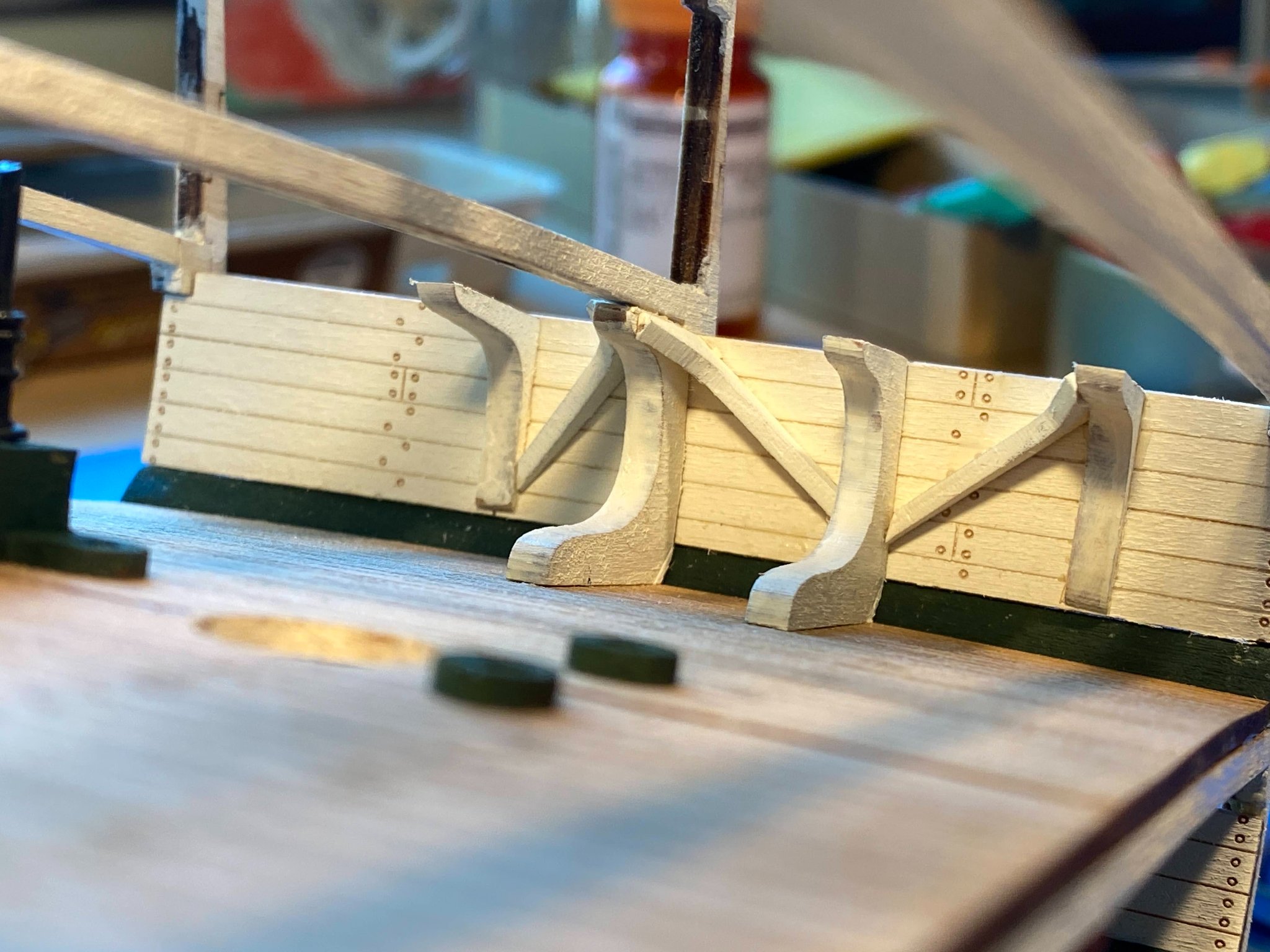
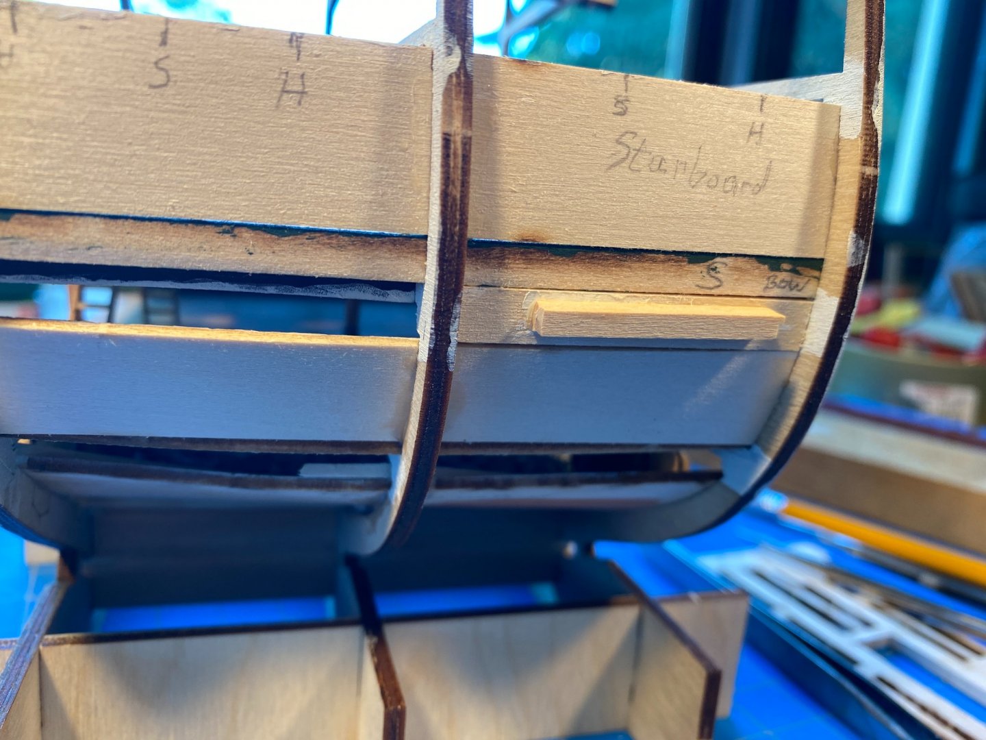
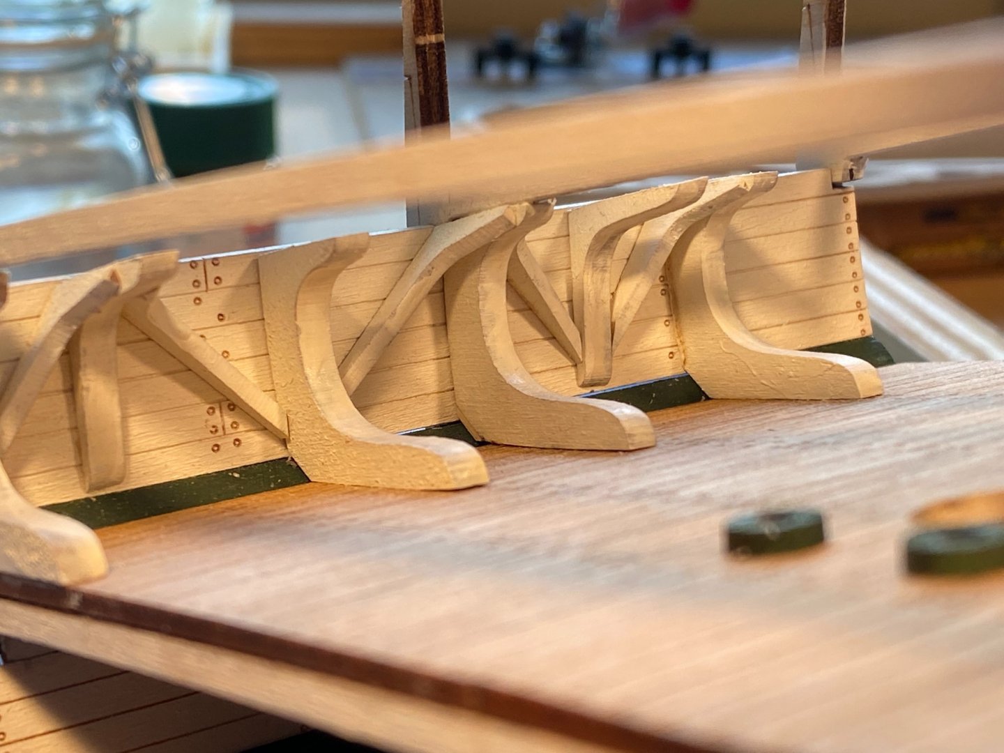
For some reason there are gaps between the top of the orlop deck sidewalls and the bottom of the berthing deck waterways. The instructions suggest filling them with ¼“ x¼“ strips, noting that once glued in place they would need to be trimmed to make room for the hull planking. A ¼“ by 1/16” plank made a lot more sense to me, these planks being a continuation of the 1/16” thick sidewalls, and they clearly wouldn’t interfere with the hull planks. But after cutting and painting these four planks, I discovered they are very difficult to properly place, since there is nothing to hold on to. A ¼“ x¼“ piece would be a lot easier to hang onto. I solved that problem by gluing a ⅛” square handle on the back of each one, which worked quite well, and the handles will clear any hull planking, without any trimming. Project knees . . . gotta give that gun deck above a lot of support. On each side there are five standard knees (those which rest on the deck), three hanging knees, and seven diagonal knees, for a total of 30 of these things counting both sides (fortunately all laser-cut). It took me a while to discern from the instruction photos exactly what goes where, and the plans don’t show them, but I think I got it right. Working your way aft, it’s standard (under a beam), hanging, standard, standard (under the middle beam), hanging, standard, hanging and standard (under the aft beam). Note that the standard knees under the beams have a notch cut in them to fit the frames, while the other standard knees do not. Given the fact that my big clumsy fingers don’t work well in tight spaces, I decided to start with the knees under the middle beam and work my way toward each end. I’m glad I did. The laser-cut standard knees don’t fit well, especially lining up with the waterways (in part due to the fact that my waterways don’t exactly match each other). With quite a bit of shaving and carving, and the addition of a few shims, I got them to fit reasonably well. Probably overkill since once the gun deck is installed above, it will be difficult to see any of this handiwork. Nevertheless it was fun, and good practice for the knees at either end, where the fit will be pretty visible. The instructions seem to contemplate putting all the vertical knees in first, then adding the diagonal ones between them. I think it’s a better idea to install a diagonal knee after each vertical knee is glued in, as you work your way fore and aft from the middle beam. The more knees that are in there, the harder it is to get at the interior spaces into which the diagonal knees need to be installed. The instructions note that the diagonal knees come in two sizes, but they don’t say anything about where the four larger ones are to be placed. It seemed pretty obvious to me though that they belong in the two spaces forward of the middle beam. Two more vertical and two more diagonal knees and each side, and I'll be finished with the knee project (on this deck anyway). 😊


- 163 replies
-
- 6
-
-
- Model Shipways
- Constitution
- (and 2 more)
-
Thanks Gary for the kind words and special thanks for the advice about not removing that beam. Probably saved me much heartache! Yes, the Inland Northwest is a great part of the country. Only problem is, relative to the 90s, it's not much of a secret anymore. 🙂
- 163 replies
-
- 1
-
-
- Model Shipways
- Constitution
- (and 2 more)
-
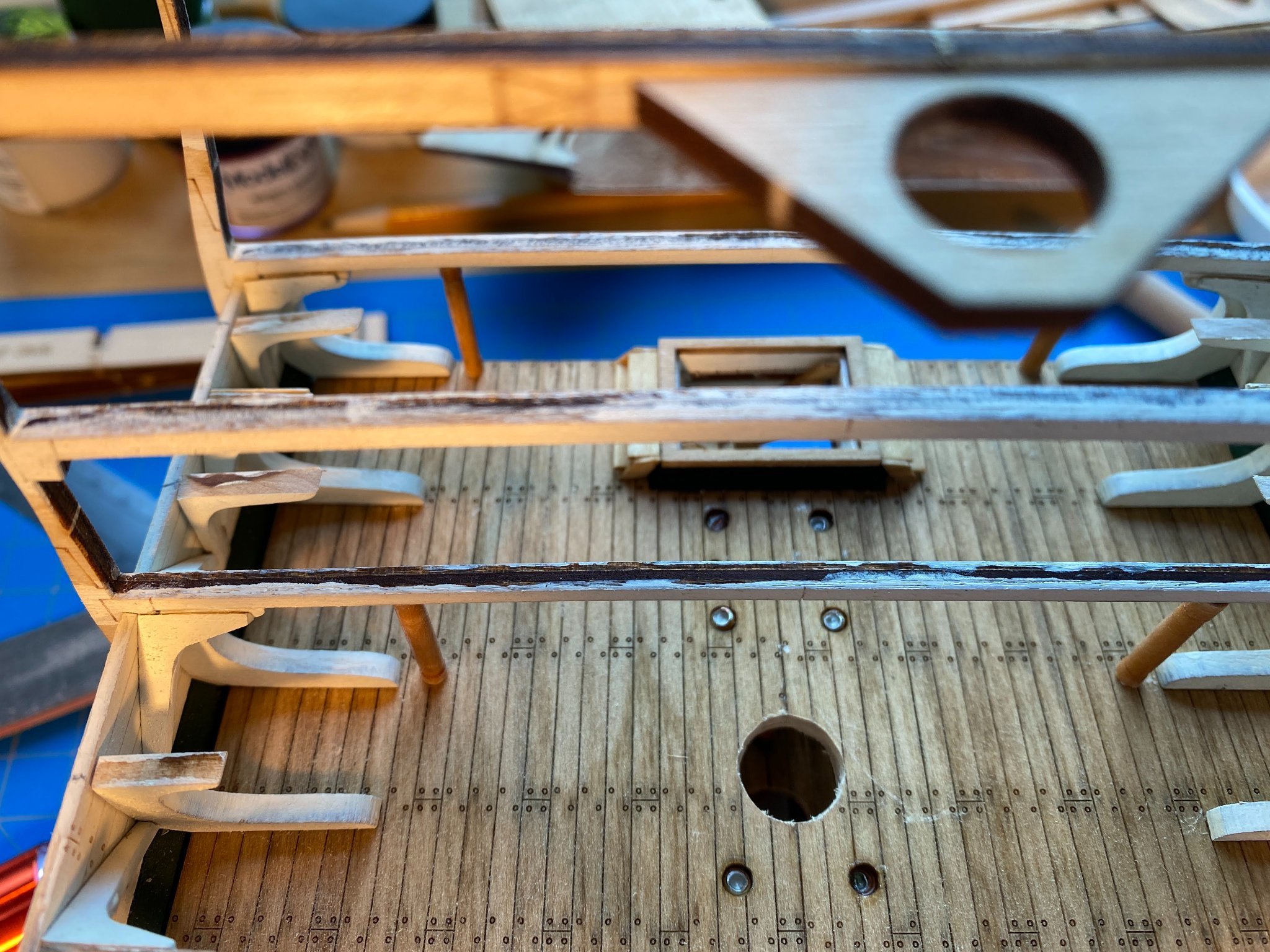
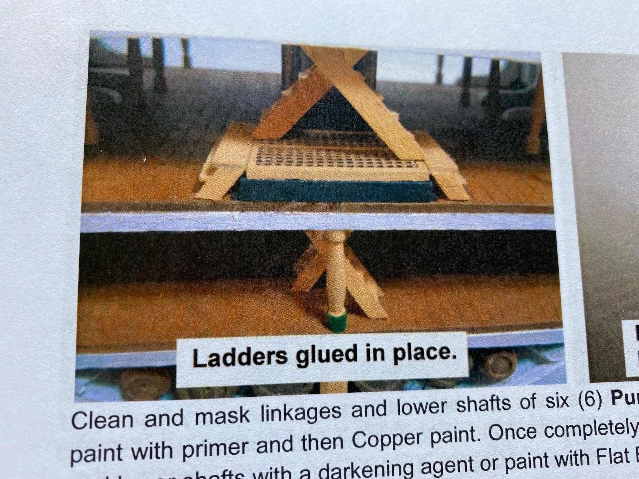
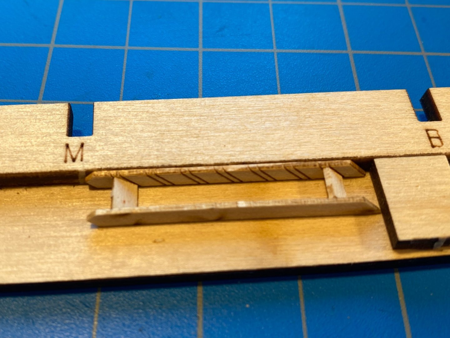
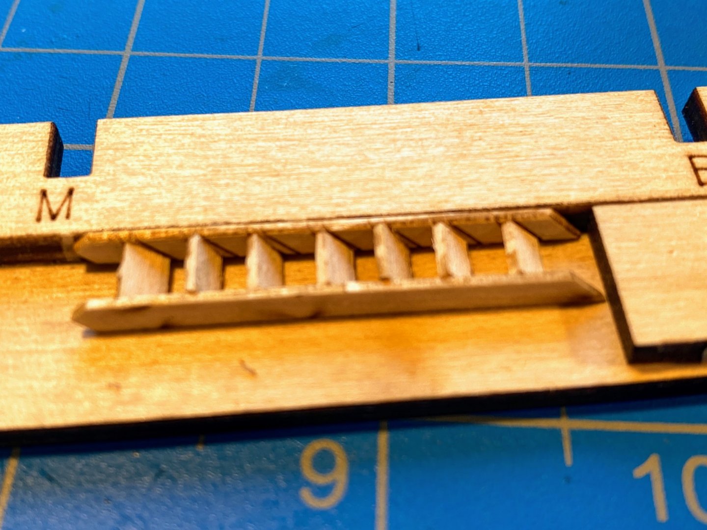
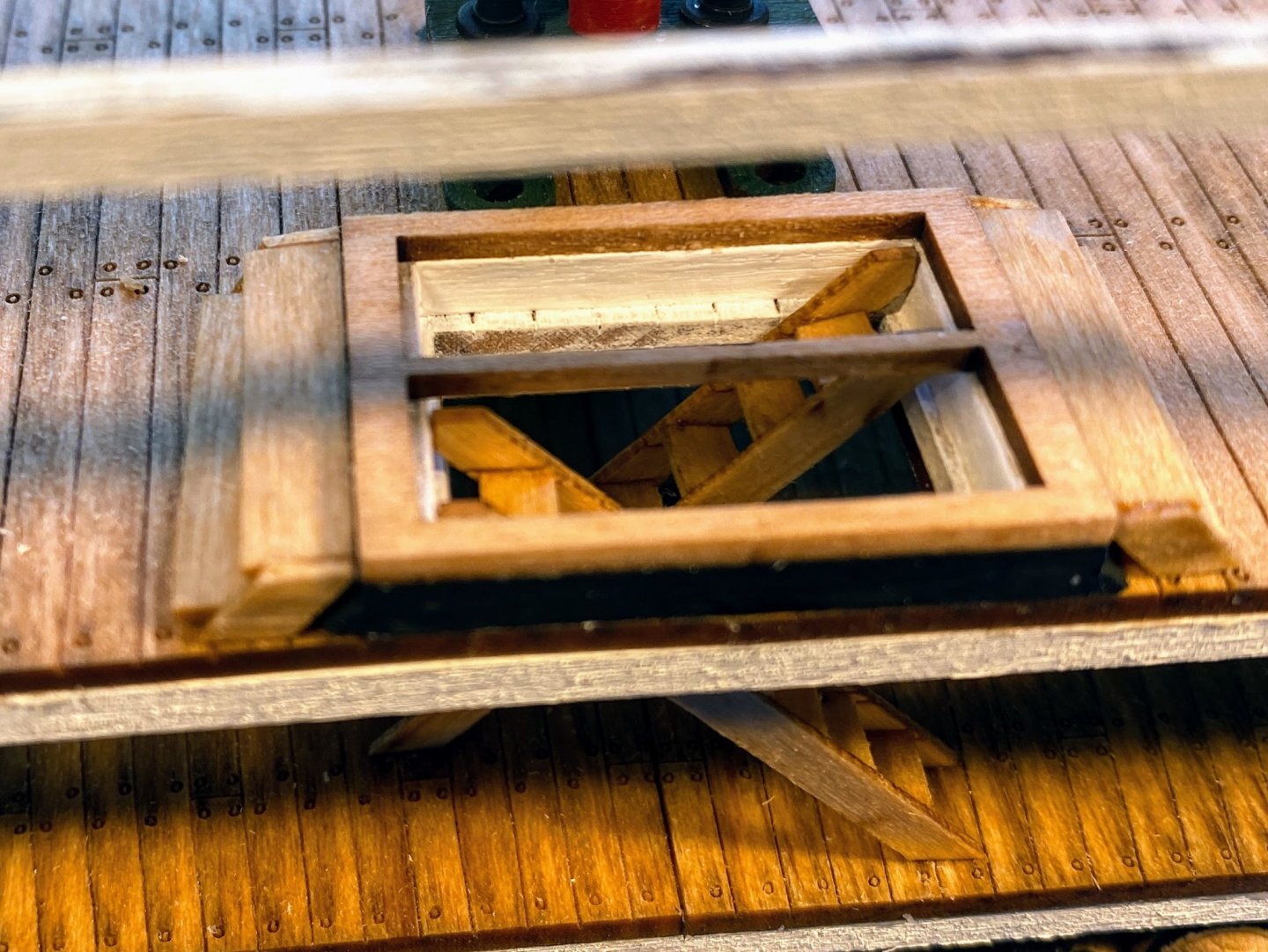
After having some difficulty putting together the steps on either side of the hatch frame, I approached building a couple of ladders with some trepidation. To my pleasant surprise, it went quite well. Unlike the similar marking on the hatchway risers, the laser scribed marks for the ladder steps only grazed the surface, and the risers were easily handled without breaking them. I made a bit of a jig, actually only a floor and a wall, and that helped in gluing the first couple of steps to one riser. But when I glued the other riser to the steps, I discovered that I did not get the two risers exactly even with each other, so I added an end piece to the jig. Fortunately the riser unevenness on one ladder isn't noticeable. Once dried and stained, I glued the ladders in place, with the pointed end of the risers leaning against the hatch frame and the diagonal end resting on the orlop deck. Then I added the remaining post with the green base. The sidewalls needed a little bit of trimming (as the instructions warned) to tightly fit between the waterways below and the deck beams above; only a couple minutes of sanding and they snapped in place nicely. Next I painted the gun deck framing pieces, and discovered a bit of a puzzlement. Unlike the just finished berthing deck below, and the spar deck above, the aft framing piece encloses the space for the stairway hatch, such that the hatch is separated from the end of the model by both a beam and a frame. The plans show the same thing. Which makes me wonder if the narrower hatch will be wide enough for two stairways. The framing won’t get glued in place for a while yet, so I’ll have some time to consider whether I want to cut that frame out or not. Now beginning to work on all the knees that support the gun deck above. . .


- 163 replies
-
- 7
-
-
- Model Shipways
- Constitution
- (and 2 more)
-
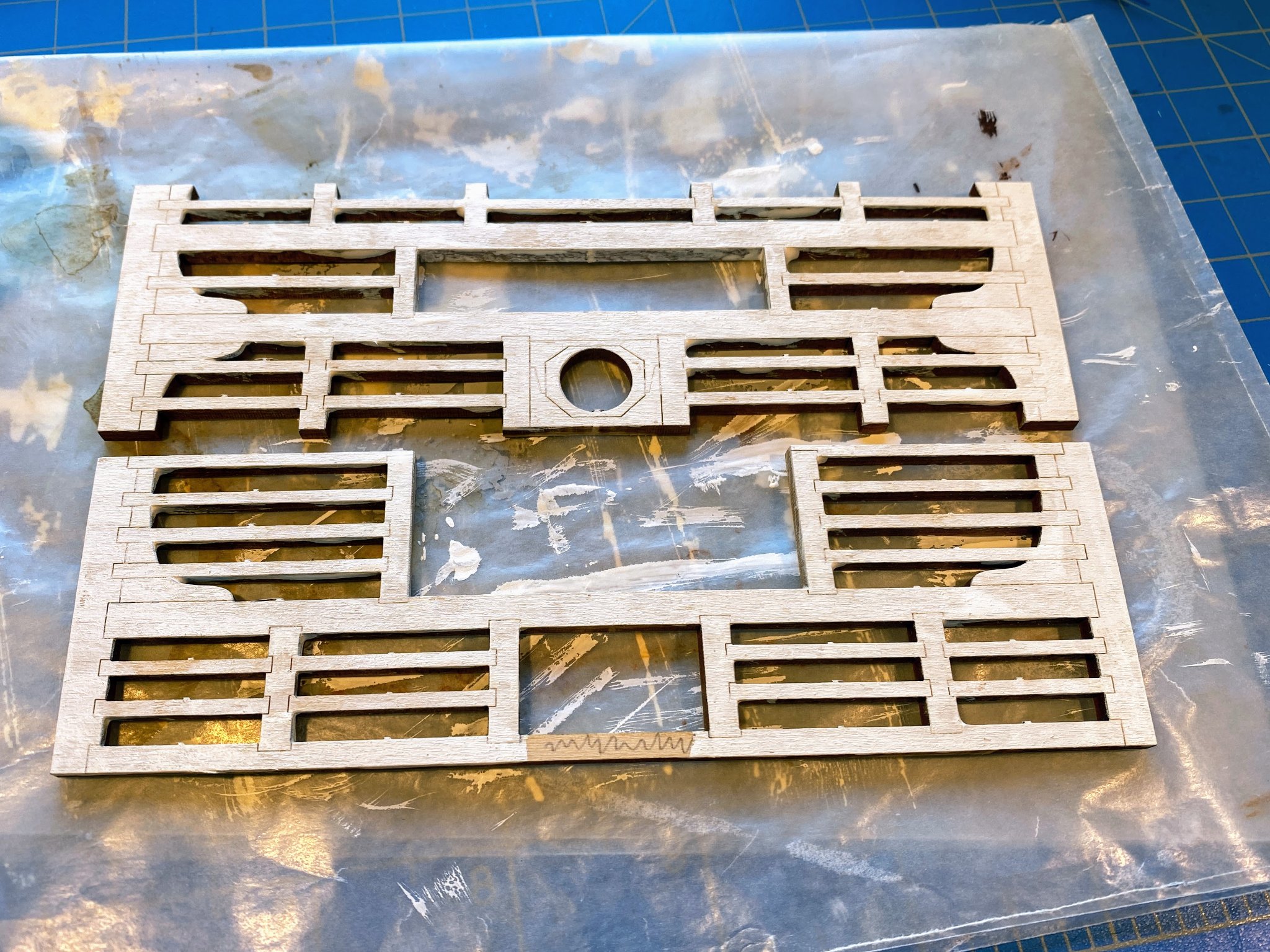
On to the berthing deck (not “birthing” as I incorrectly typed at first). The first step for this deck and the other two above it is to paint, then install laser-cut deck framing pieces between and flush with the beams and sides of the rib pieces. The instructions suggest using an iron or hair dryer to make the framing pieces conform to the gentle arc of the beams, warning not to use water. But the needed curve is gentle enough that the heat struck me as totally unnecessary. But unlike framing a hull, there is nothing to bend these framing pieces around. Perhaps the heat is intended to pre-bend the framing pieces before fitting them between the deck beams, but for whatever reason I didn’t try that. Bending them and gluing them in place proved to be a bit of a challenge . . . what seemed to work best was to first glue one in place at the middle with a drop of two of glue, then once that glue was dry, bend them and glue them at the outer edges. I did not worry about securing them with a lot of glue since the deck pieces will eventually be glued to the tops of these framing pieces and the tops of the ribs. As I did with the orlop deck, I used my Dremell to enlarge the mast hole a bit, so I’ll have some wiggle room for making a final adjustment to the mast alignment when the mast is ready to be installed, many months from now. Once I had the framing pieces glued in place, I felt I could safely install two of the posts on the orlop deck; the third (at the aft end) would have to await installation of the two ladders back there. The instruction’s pictures of these posts on the orlop deck show the base of each pole painted green, so I did that on mine. The posts on the berthing deck and the gun deck are shown stained but unpainted, so I guess I will do that too. I intentionally cut these posts about 1 mm too long so I could sand them down to a tight fit. The one in the middle was a bit tricky to get in place given the tight space to work with. You’ll definitely want to do this before gluing the berthing deck in place, so you can work through the numerous holes in the berthing deck framing. With some long tweezers I eventually got it situated the way I wanted, then applied a very small drop of instant drying CA glue at each end of the post to provide some assurance that it will stay put. On the orlop deck, the instructions have you install the deck and the sidewalls, then shape, paint and glue the waterways in place, covering where the deck and sidewalls meet. On the other decks, they have you glue the waterways in place first, then install the deck and walls, so that the edges of each butt up against the shaped edges of the waterways. This approach is consistent with what the plans show for all the decks, including the orlop. Shaping the starboard waterway went quite easily. The port one was more of a challenge, as the curve of the laser-cut waterway was significantly greater than the curve of the three ribs to which it is to be glued. I ended up cutting a notch in that waterway for the middle rib, which I neglected to get a picture of. Once shaped and painted, I glued them in place, with the berthing deck loosely in place for fitting purposes, then removed for the next steps. I next assembled the hatch framing for the stairway, with two laser cut pieces dubbed lower and upper hatch frames. What is odd is that the interior of the upper hatch frame is filled with a grate, attached to the frame with one small tab. Most of the pictures in the instructions show the grate removed, but one shows it with the grate in place, blocking access to the ladder coming up from the orlop deck. Perhaps that denial of access was secured by a lock because the grog was stored below? In any case, I removed (and saved) the grates. Short steps need to be built with laser cut pieces on either end of the hatch. The tiny riser pieces were very difficult to accurately place . . . take a deep breath and they blew off the table, sneeze and then blew across the room. Also, the risers are laser etched to show the location of each step. Unfortunately the laser etching goes three quarters of the way through the 1/32” piece, leaving only a few fibers of wood holding it together. Two of the four risers broke, but I was able to glue them back together with a drop of instant drying CA. The instructions suggest staining the upper hatch frame and the steps (and looking ahead a lot of other things) with “Natural” stain, which leaves them too light IMHO. I mixed one part Golden Oak with four parts Natural, and got a color I liked. In the photos, though, it’s hard to distinguish the colors of these fixtures from the color of the deck, but not so in real life. The pump assembly went together easily. The rods needed to be cut back a bit to fit below where the gun deck will be above. The instructions tell you to glue the hatch and pump assemblies to the deck, then glue the deck in place. I did that with the hatch but not the pump, because I wasn’t at all sure I could get the deck in place with the pump rods sticking up -- those rods stick up slightly higher than the bottoms of the beams and deck framing above. After the deck was glued and drying, I used long tweezers to place the pump assembly, getting it lined up properly with two of the four pipes dry fitted in place. Then I lifted the pump assembly, put a small dab of glue beneath it, and lowered it back onto the deck. Edit added 7/10 . . . I strongly suggest gluing this pump assembly and the two green flanges to the deck later, after gluing the bilge pump pipes in place. See my early July posts below. The bent pipes can be worked through holes in the relatively thin deck pretty easily, but add the thickness of the pump assembly and flanges, and it becomes much more difficult. Both are easy to add later, if done before gluing the gun deck framing in place. Next . . . real ladders, 8 more posts, and sidewalls.


- 163 replies
-
- 7
-
-
- Model Shipways
- Constitution
- (and 2 more)
-
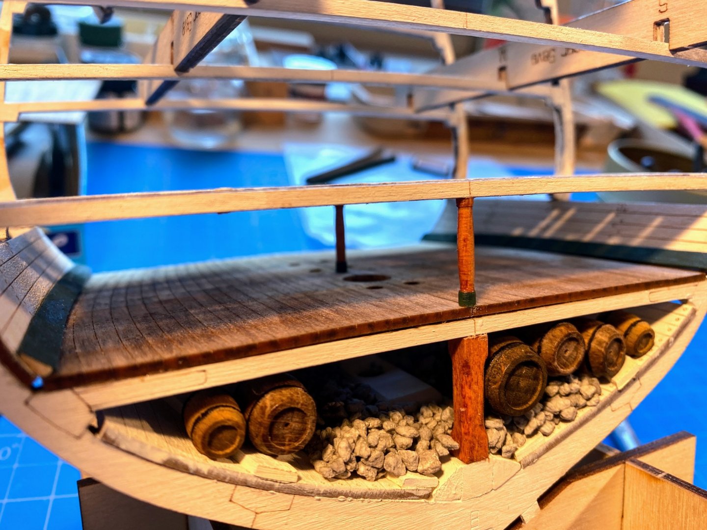
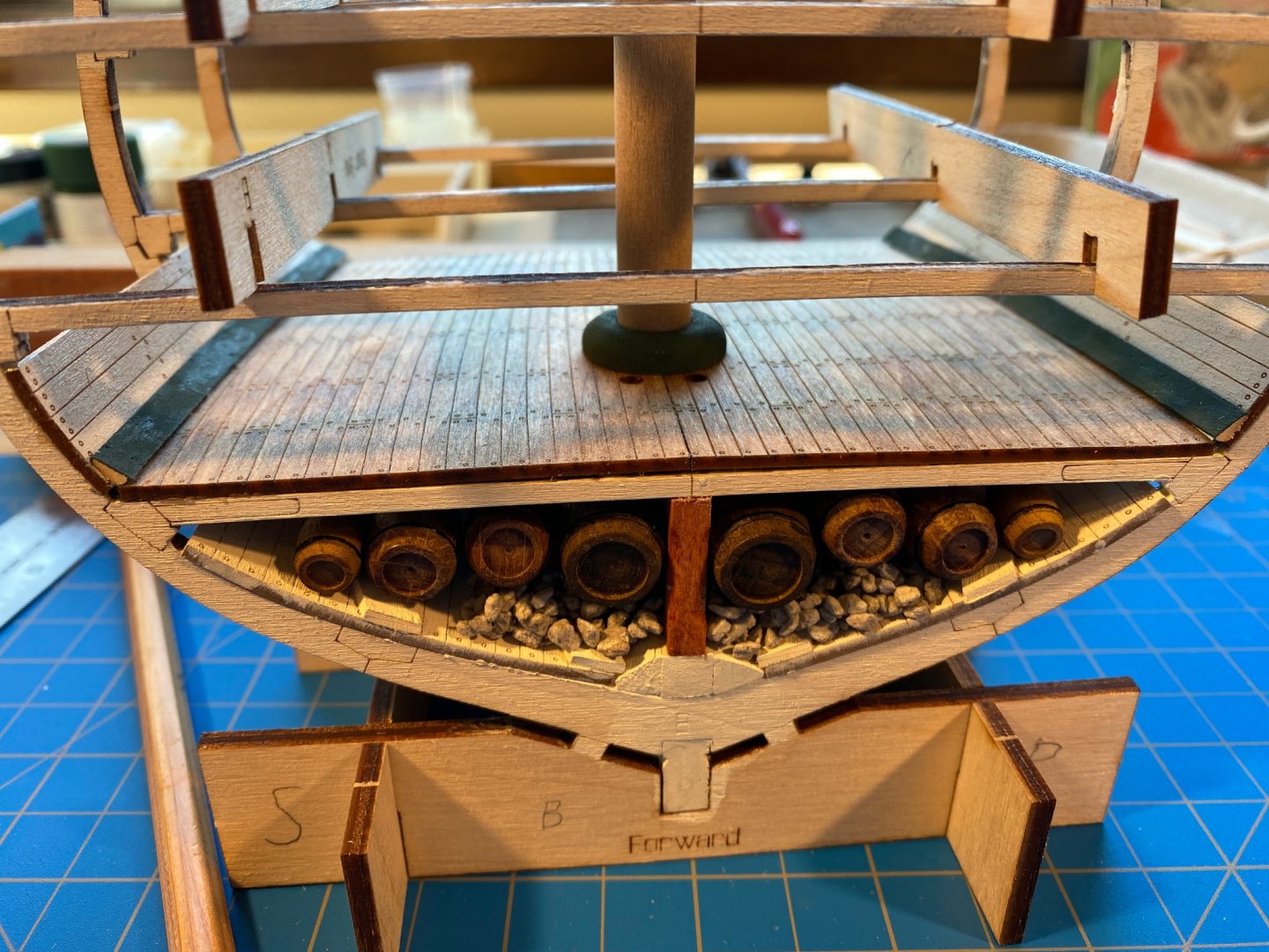
Thanks Matt. The glue held the gravel quite well. I turned everything upside down after the glue had dried, and only 2 or 3 individual stones fell out. Just to be sure, and probably unnecessary, I added a coat of matte polyurethane. As for the barrels, just last week two of them came loose and I pulled them out. Something of a blessing in disguise because it enabled me to see where the placeholder mast met the mast base, and I discovered I was not getting the screw I put in the end of the mast into the hole. I think I will leave those barrels out until I install the mast permanently, just so I can view what's going on in there.
- 163 replies
-
- 2
-
-
- Model Shipways
- Constitution
- (and 2 more)
-
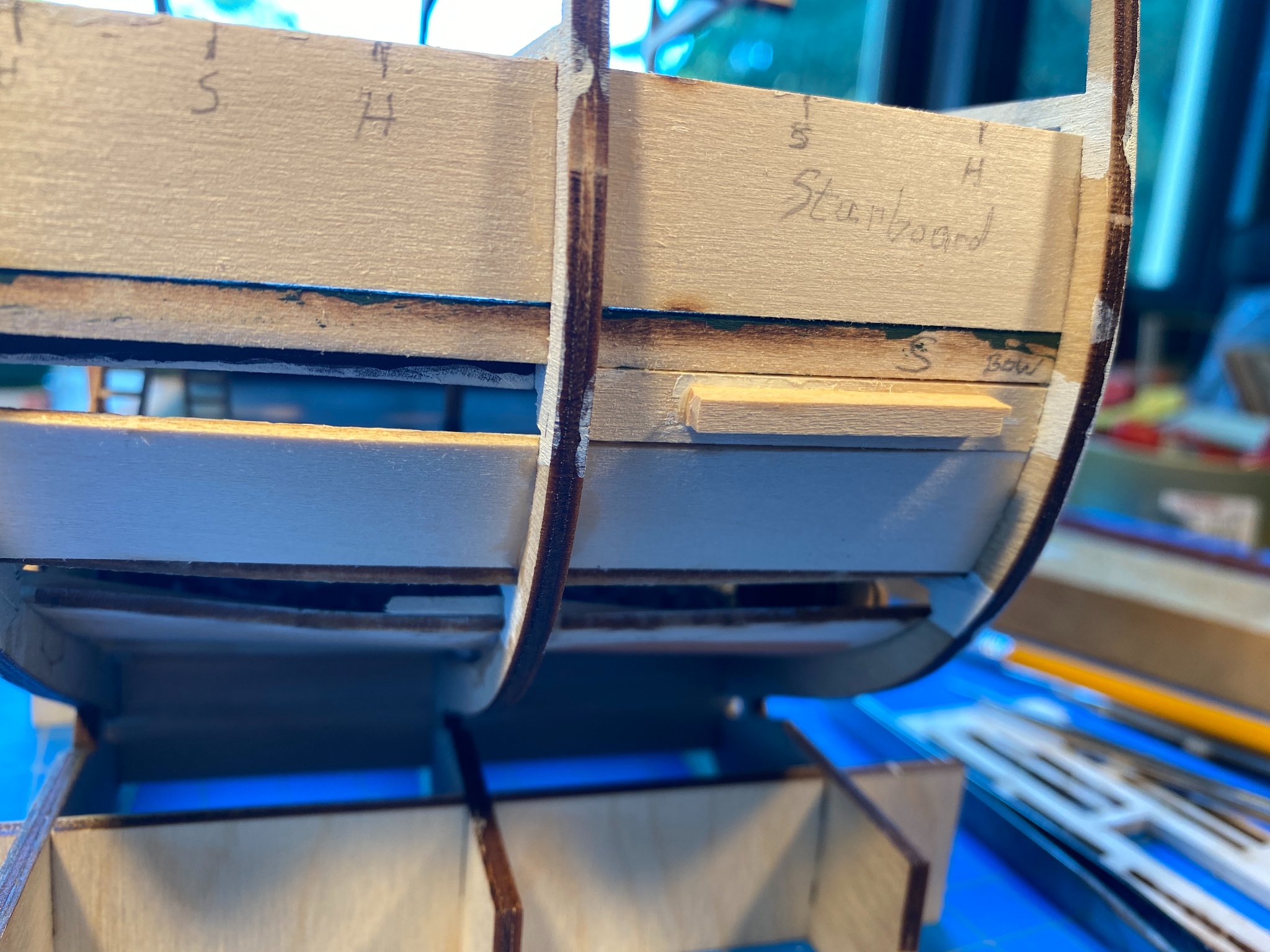
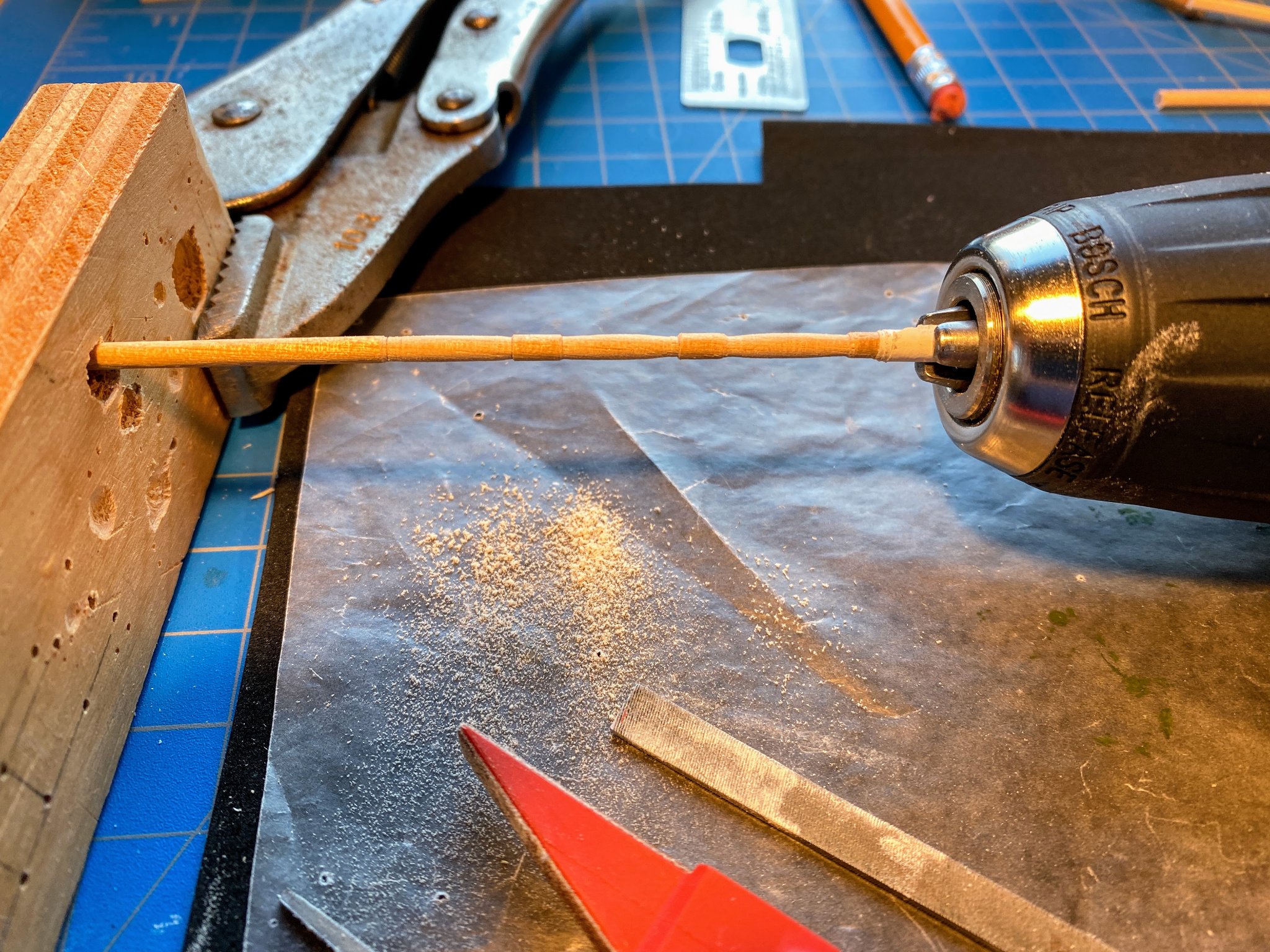
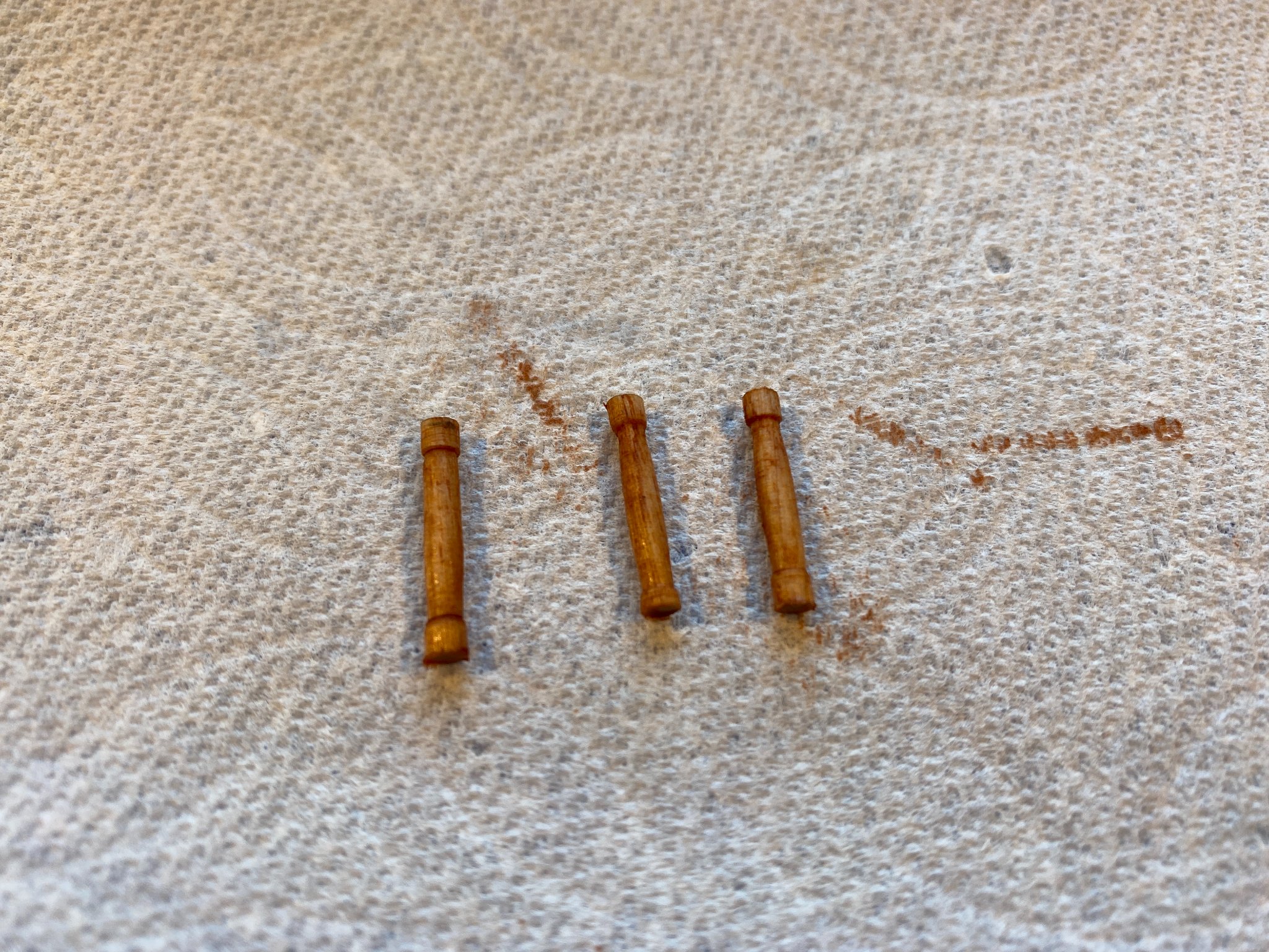
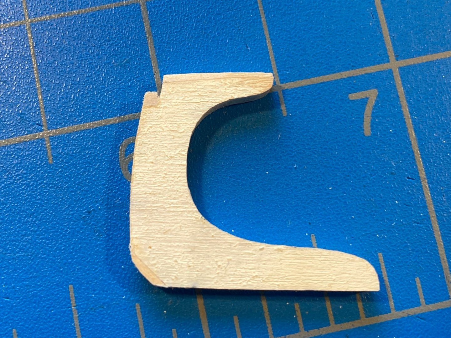
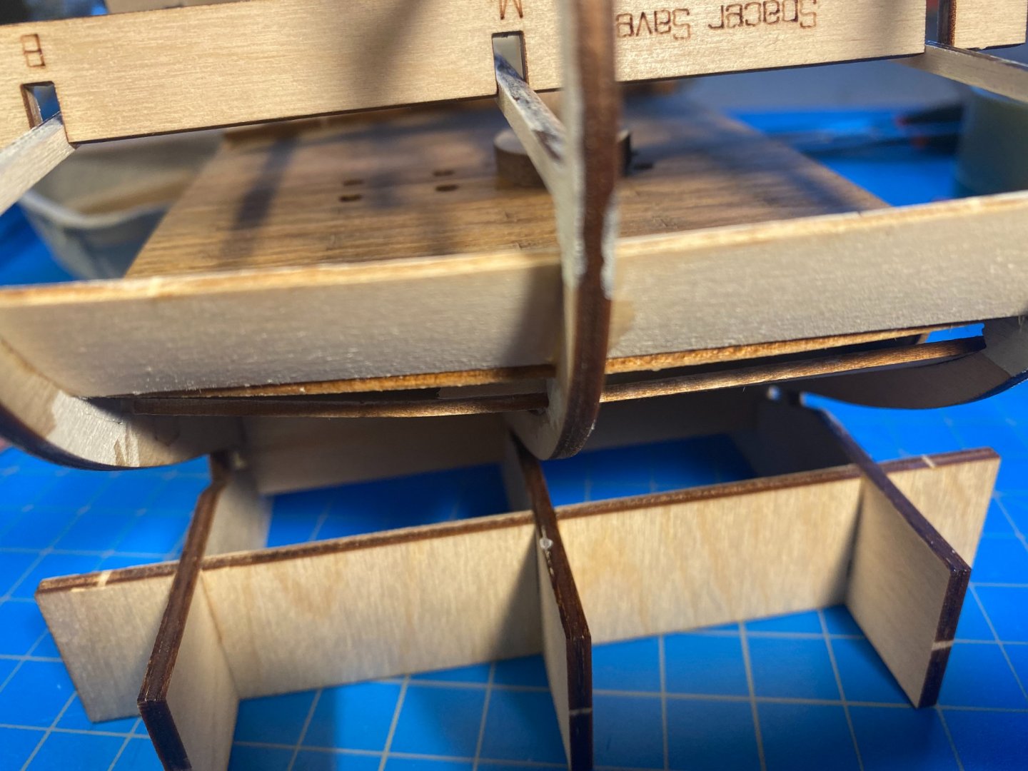
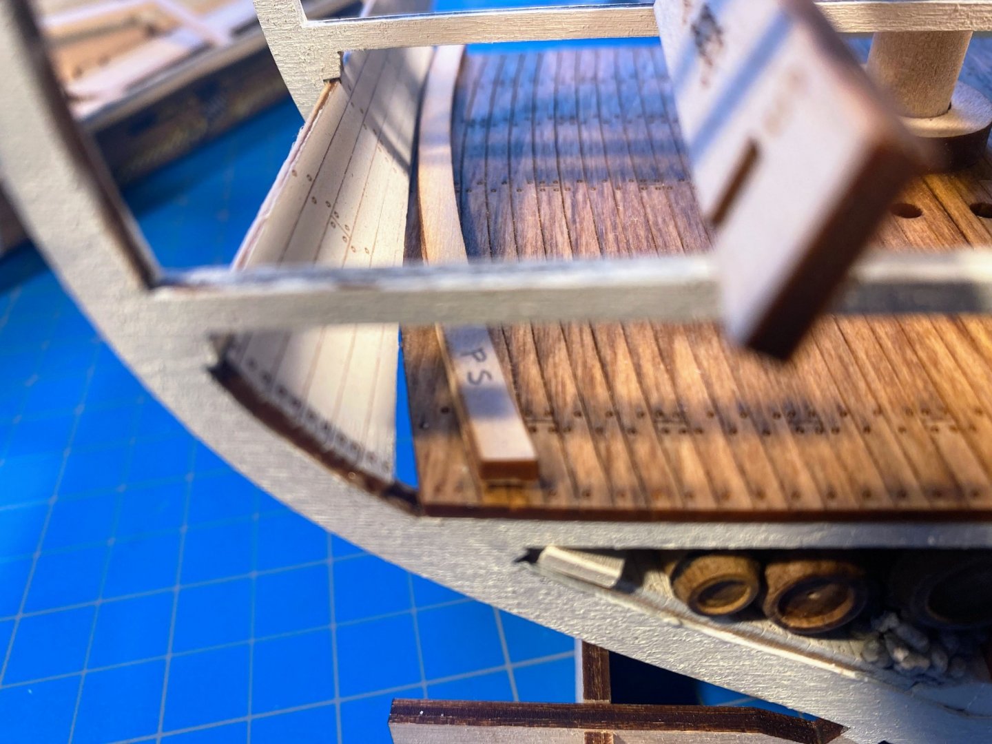
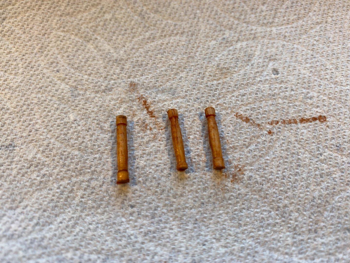
At each deck level the place where the deck meets the sidewall is covered by a waterway (in the instructions referred to as a “stringer” at the orlop deck but everywhere else, including all decks in the plans, referred to as a “waterway”). Sanding the sidewalls to fit between the deck and the ribs above and then gluing them in place to the inside of the ribs, I wasn’t very careful about how the sidewall met (or didn’t meet) the deck, figuring gaps would be covered by the waterway. The waterways are supplied as curved laser-cut pieces (which need to be bevelled lengthwise to fit), and when I cut the two out for this deck, I discovered that due to my lack of care, the curve for the waterway was much greater than the curve where the deck and sidewall met. The discrepancy was great enough that the laser cut pieces simply wouldn’t work. So I cut a 1/16th” by 3/16th” strip and beveled it lengthwise with a Dremel to fit between the deck and the sidewall. Only problem was that I occasionally let the Dremel run off the end I wasn’t holding at the time, accidentally shaving off the corners resulting in a pointed end, which wouldn’t do at all. So I cut two new strips, about half an inch longer than needed, beveled them (again making a mess of the ends), painted them dark green, glued them in place, and cut off the excess. Also laser-cut are three “mast surrounds”, which not surprisingly surround the mast on the orlop, berthing and gun decks. As instructed, I shaped them and painted them the same dark green as the waterways. I slipped one of them onto the placeholder mast and slid it down to deck level, but I decided not to glue it in place just yet. I like to occasionally read a few pages ahead in the instructions to see what is coming up, and doing that I noticed a picture with the next deck glued in place and with a post midships on the orlop deck. The instructions don’t say anything about putting any posts at that deck level (unlike the posts in the hold) and the pictures don’t show a post there until the berthing deck is in place a few pages later. But the plans show 3 posts down the center line of the orlop deck. Reading ahead, the instructions get interesting. They say to shape 13 posts (or “stanchions” as they are referred to) from a 1/8th” dowel, then install 8 of them between the berthing deck and the beams above, and to set aside “the remaining four” to be installed on the gun deck. I pulled out my trusty HP 12C calculator and confirmed my suspicion that that left one unaccounted for. But even more puzzling reading ahead in the instructions about the gun deck (and doing a search in the digital version of the instructions), there is nothing said about installing four (or five) posts (or stanchions) on any other deck at all. The plans are more helpful, showing 3 posts on the gun deck, in addition to the 3 on the orlop deck. Adding those to the 8 shown in a picture of the berthing deck, it looks like I’ll need 14 of these things. I don’t own a lathe, but I fashioned a reasonable facsimile of one with my drill and a block of wood which conveniently has a lot of holes in it. I then shaped three of them for this deck, stained them with the same stains I used for the posts in the hold below, and set them aside to be glued in place later. That would be 3 down and 11 to go.


- 163 replies
-
- 8
-
-
- Model Shipways
- Constitution
- (and 2 more)