HOLIDAY DONATION DRIVE - SUPPORT MSW - DO YOUR PART TO KEEP THIS GREAT FORUM GOING! (Only 24 donations so far out of 49,000 members - C'mon guys!)
×


BobF
-
Posts
175 -
Joined
-
Last visited
Content Type
Profiles
Forums
Gallery
Events
Everything posted by BobF
-
 Thanks, David. I've really learned a lot from this group. The least I can do is return the favor. I'm currently playing with the friezes and the molding strip. Hopefully, I'll be posting some photos soon. Bob
 -
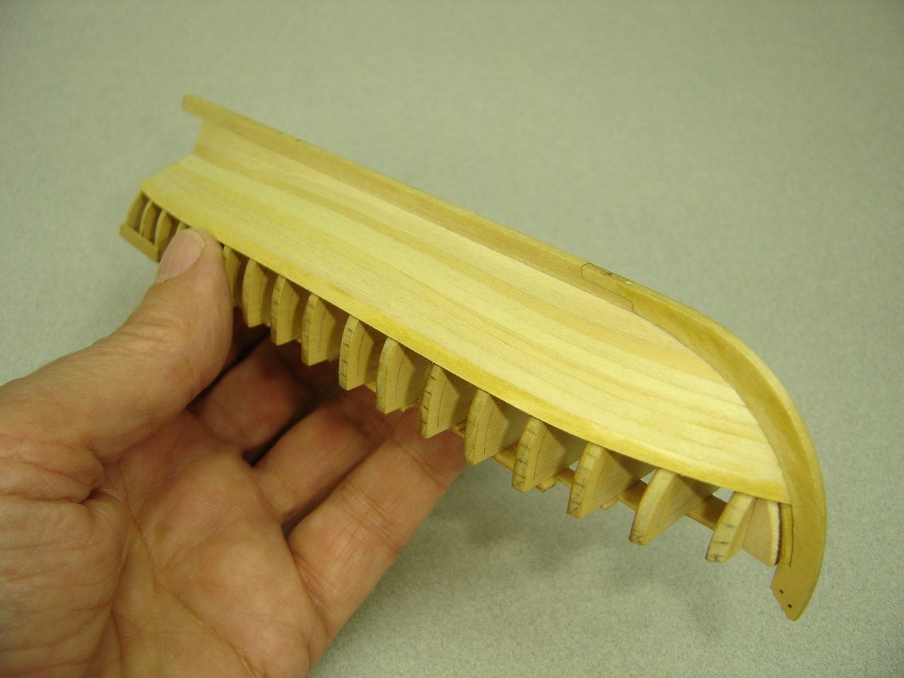
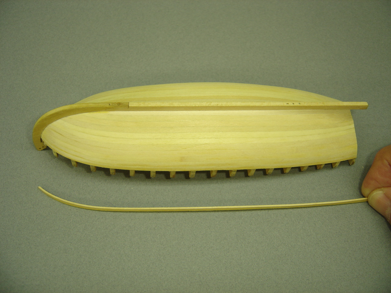
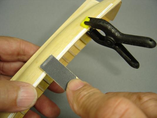
Thanks to all of you for your positive comments. I failed to mention one other benefit concerning the Evergreen plastic strip. In addition to producing a consistant overhang, it allowed me to get a nice crisp edge on the caprail. I'm hoping that this will also result in a clean, sharp line between the red and the white pin stripe when the model is painted. Bob
-
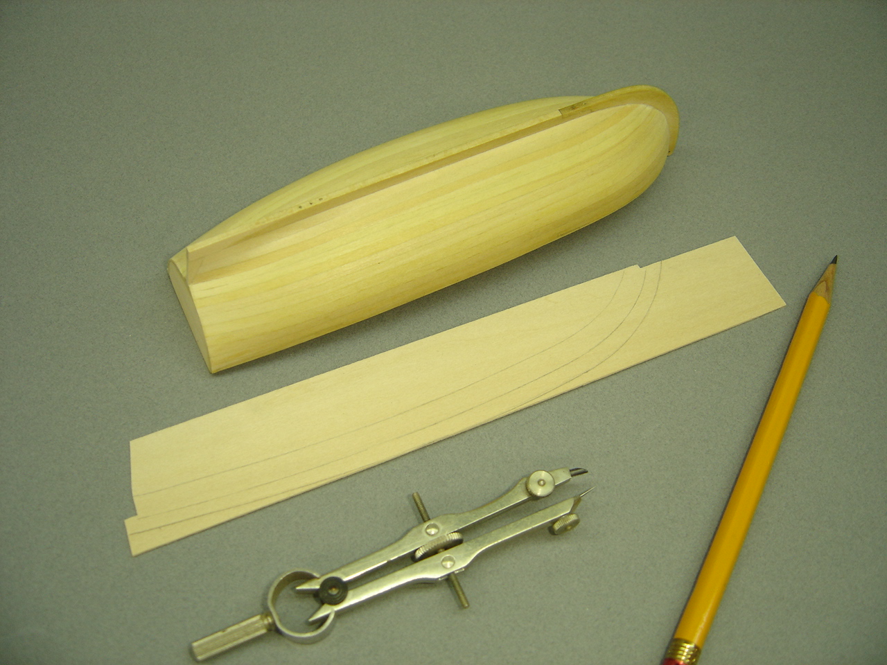
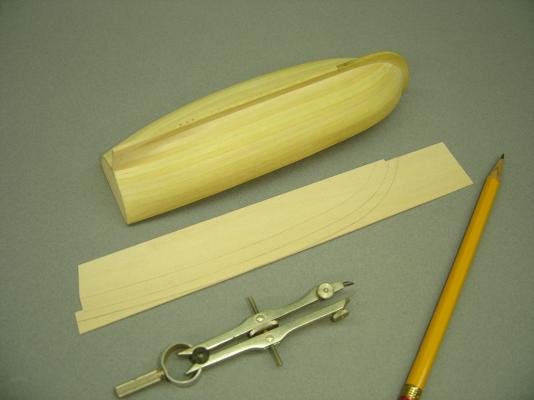
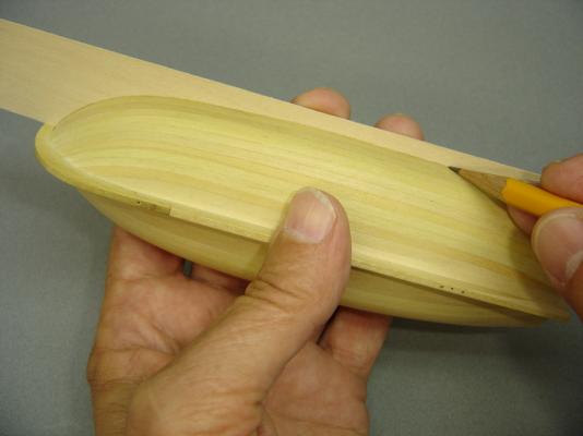
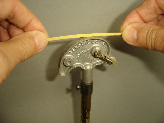
I probably drew my two parallel lines way too far out, but I'd rather be safe than sorry. The instructions state that the inboard and outboard overhang for the caprail should be 1/64", which is about .016". I took a strip of Evergreen plastic that was approximately .018" thick, and used it as a reference for sanding the caprail to the proper width. If you look closely, you can see pencil marks on the plastic. I kept sanding until those marks started to disappear. That worked out pretty well. It gave me a consistent edge along the entire hull. I have to admit that I thought such a small amount of overhang wouldn't be enough, but it turned out to be just right. I really have to learn to trust Chuck's judgement. He hasn't been wrong yet!
- 277 replies
-
- 8
-

-
- model shipways
- 18th century longboat
- (and 1 more)
-
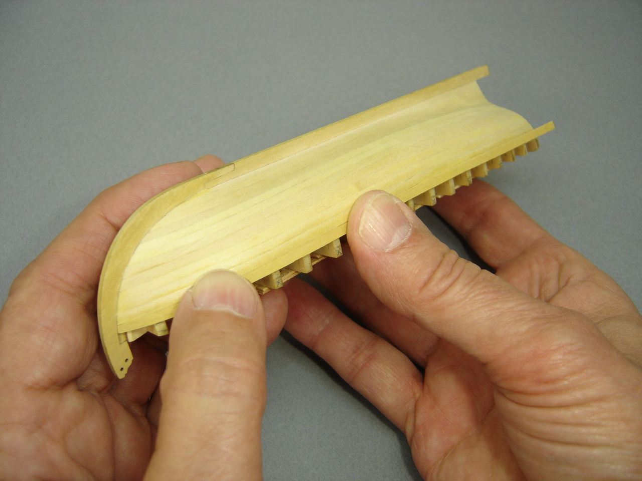
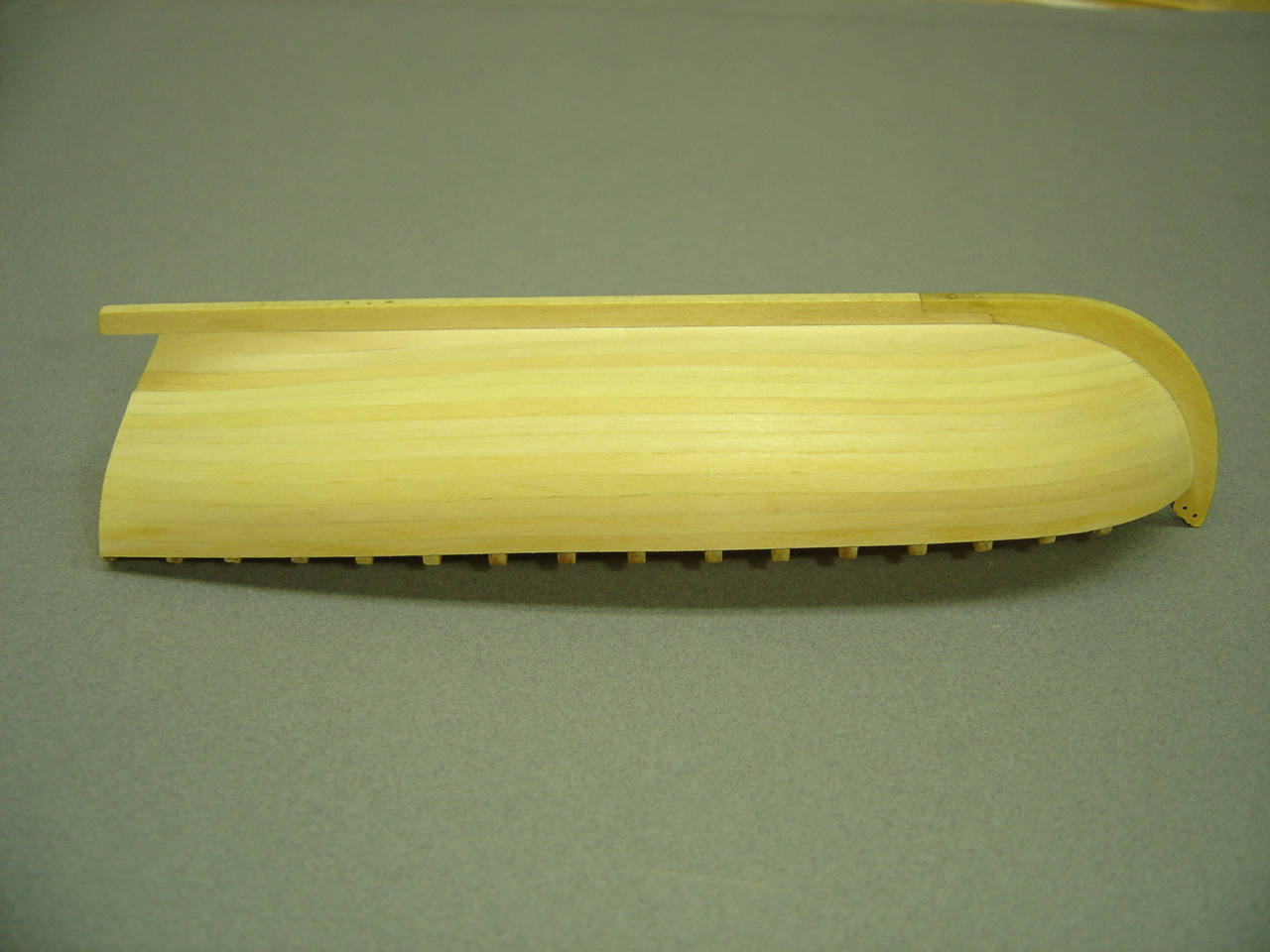
Well, I'm working on the cap rails. Really nothing monumental there. So far, it's been the easiest procedure on the model. Since I'm taking photos of the procedure for our Tri-Club Group Build, I thought I'd post a few for this group.
- 277 replies
-
- 4
-
-
- model shipways
- 18th century longboat
- (and 1 more)
-
HI Dan, I agree with Toni. I had the same doubts when I started gluing the bulkheads to the false keel. It all works out ... really! One thing to watch out for: You don't want the bulkheads to be too tight, when you prefit them. If you are using a PVA glue, the basswood will swell, and you might have a problem getting the proper alignment. I had to remove one bulkhead twice before I could get it correctly aligned. Also, if the fit is too tight, you might start stressing the frame while you're ligning up the bulkhead. Like Toni stated, keep the keel assembly in the building board as much as possible. It's looking good, mate! Bob
-
Dan - Since you don't have any bulkheads mounted yet, it shouldn't be a problem tapering down that area. Bob
-
Hi Dan, You're off to a good start. Keep it up, and you'll pass me up like I'm standing still! Come to think of it, I AM standing still. Gotta get goin again! One thing I noticed, and it might just be the photo, but the aft edge of your false keel needs to be 1/32" wide from the bottom up to the notch that the transom rests on. Otherwise, you won't have room for the planks to butt up against the stern post. Keep up the good work, mate! Bob
-
Nice pedestals, Chuck. I like the proportions very much. They don't look "clunky" to me. Bob
-
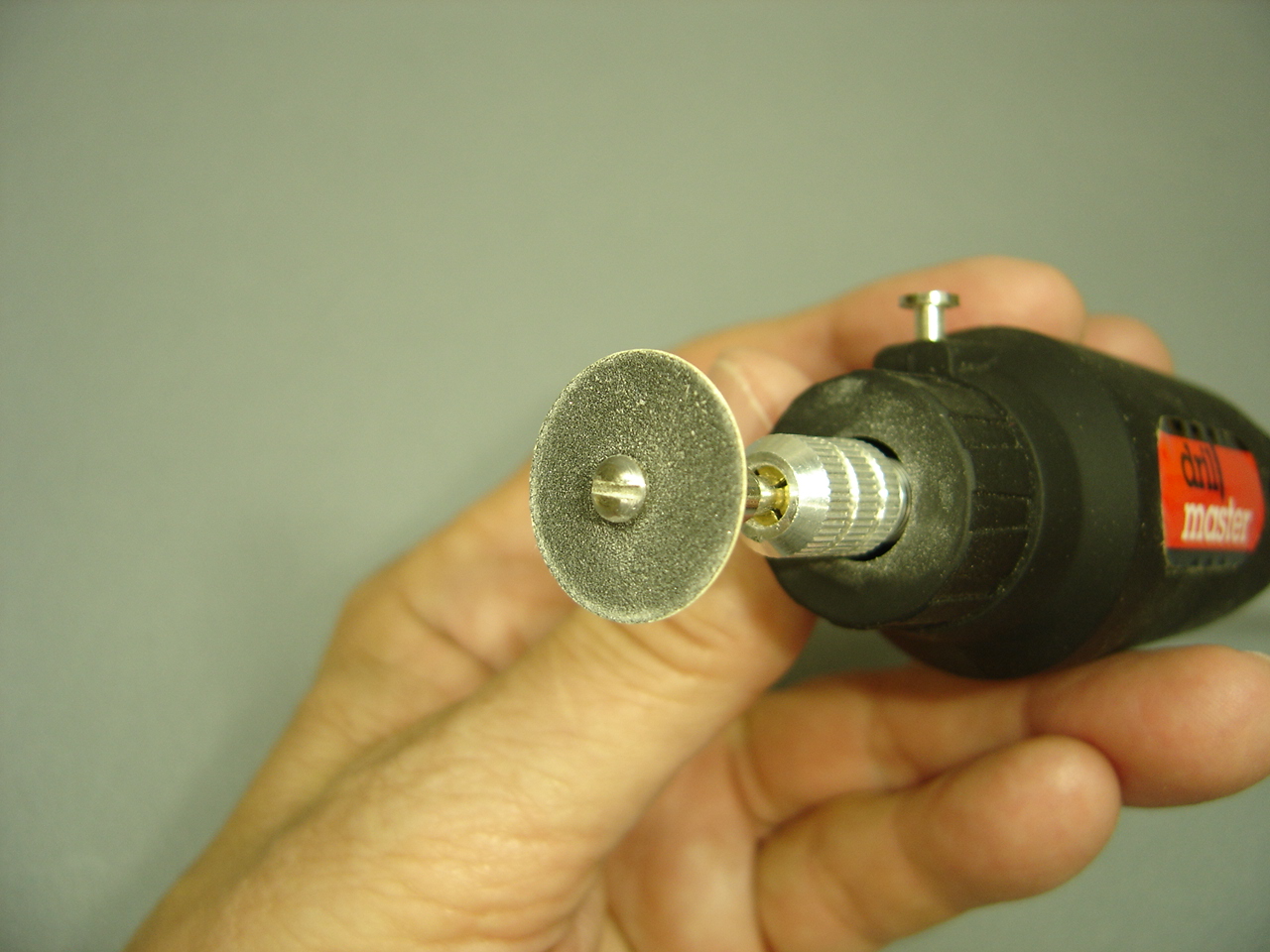
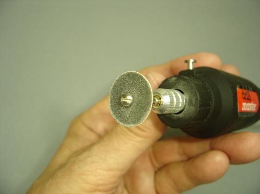
Chuck, After my last post, I wanted to see if these little discs could be made with regular sandpaper. The discs that I am using are nothing more than a somewhat stiff 3/4", 220 grit, disc with a hole in the middle. I took some material from a file folder, and glued it to the back of some sandpaper. Using a compass, I drew some circles, and cut the discs out. Punched a hole in the center, and gave it a try. It worked, except for the fact that the disc was a little too rigid. The sanding process left irregularities in the surface of the frame. I think the problem was the Elmer's glue I used. It dries hard, rather than staying flexible. It's possible that a contact cement might work a little better. Anyway, it's something you might want to experiment with, if there ever is a need again. Bob
- 277 replies
-
- 2
-
-
- model shipways
- 18th century longboat
- (and 1 more)
-
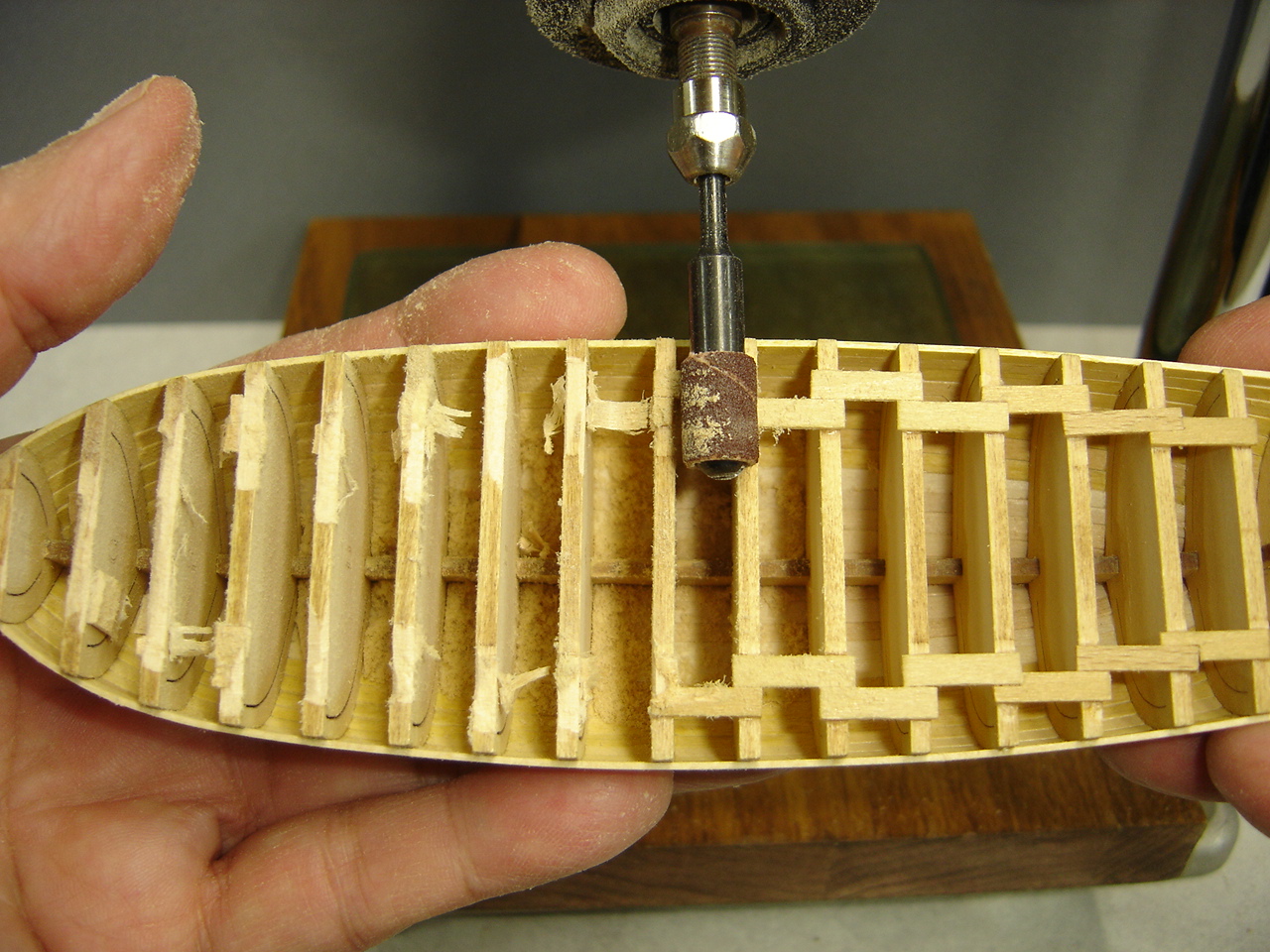
You are correct that these little units do not have variable speed capabilities, but I got around that by using an old Dremel variable speed unit. This allows me to select any speed I want, although at the low end the unit will bog down, but that's not a big deal. I've also had good luck with variable speed units made with a dimmer switch. Again, the motor will lose some torque, but that's never bothered me. Chuck, I knew someone was going to ask me about the disks. They have been sitting in my workbench drawer for 15 or 20 years, and I've never used them, until now. I'm sorry, I don't remember where I got them from. Maybe someone in the group can offer a suggestion. I know Toni used a setup that she purchased from Micro-Mark, but the last time I checked, it wasn't listed in their catalog. Bob
-
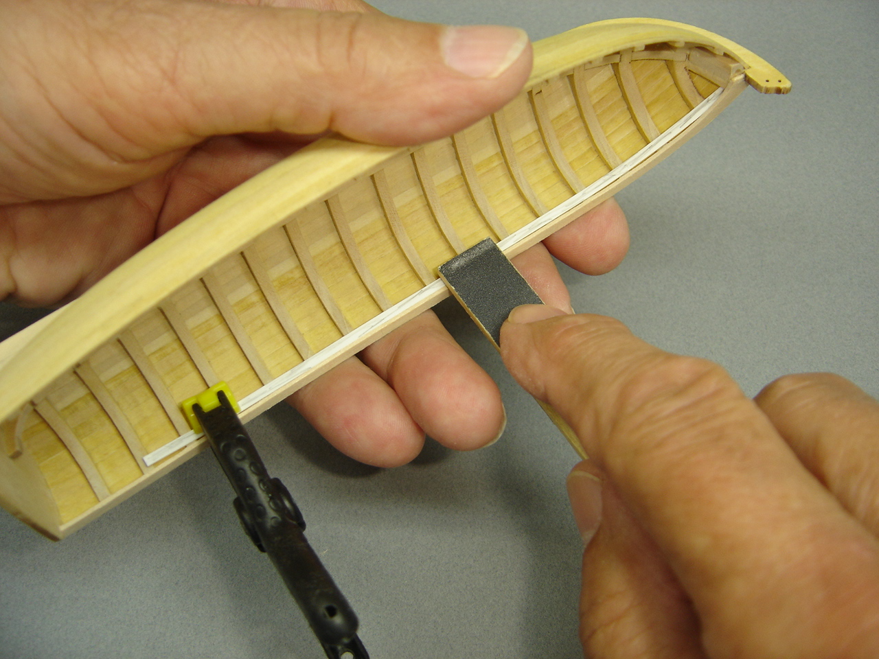
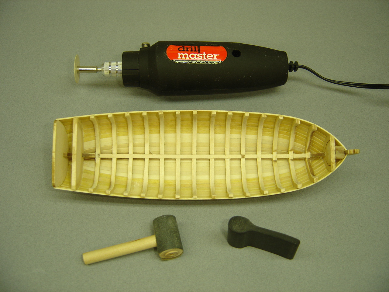
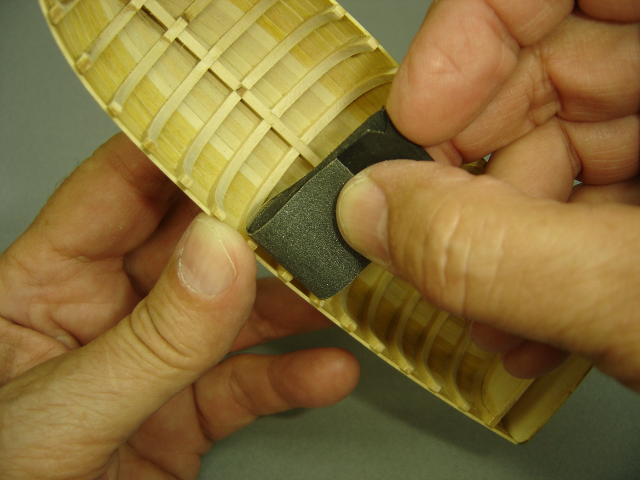
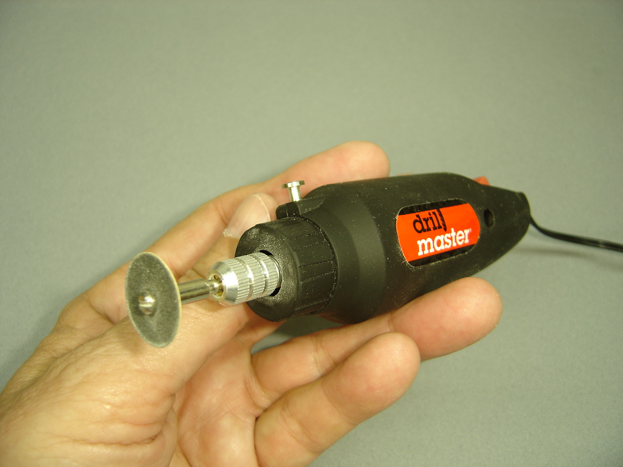
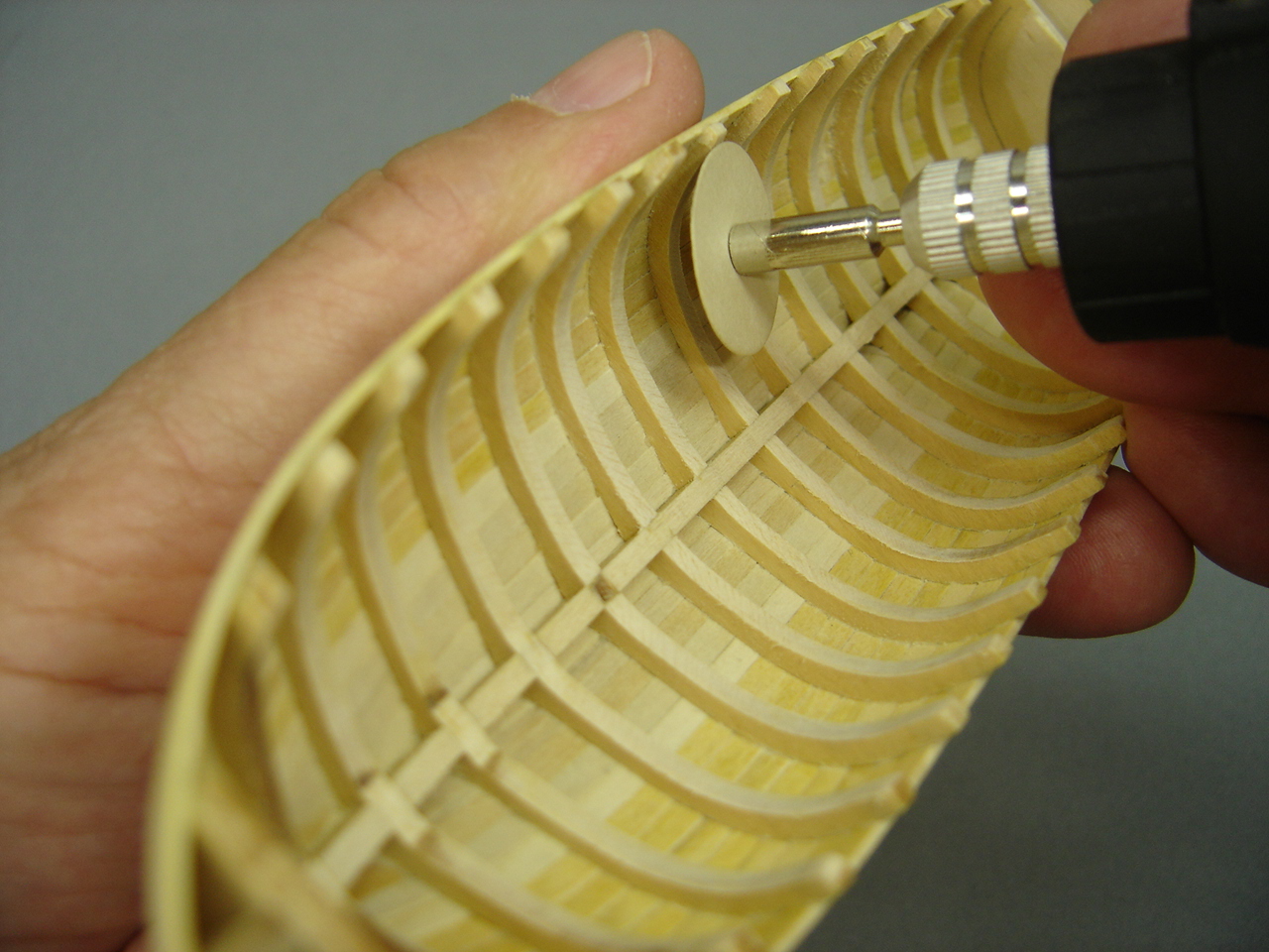
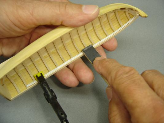
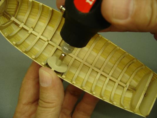
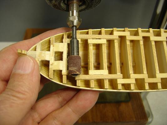
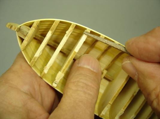
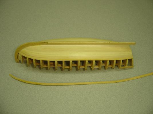
I decided to leave the forward most, and aft most bulkheads in while I thin down the rest of the frames. The first photo shows the tools that I have been using. I started out with the mallet shaped sander, which I copied from this discussion group. Although it worked well, I thought I'd try the rubber device that was cut from a larger piece. This was more convenient since I could easily rotate the sandpaper as it lost it's grit. At this point, I happened to speak to Toni, and she suggested using a Dremel Moto Tool, which could speed the process up quite a bit. Although I have a Dremel, I decided to use a smaller and lighter unit that I purchased at Harbor Freight. For light duty work, this tool works quite well, and I was able to get it for only $9.00 on sale. It runs off of a power pack, which I plugged into a Dremel variable speed drive unit. The biggest problem is the screw head that holds the 220 grit sanding disk in place. I chamfered the edges so it wouldn't damage the model, if the head rubbed up against it. That's worked out well. The sanding disk is flexible, which also helps. I tried a coarser disk, but it started taking too much off, and I wasn't happy with the results. This little power tool is really speeding up the process, but you have to use a light touch, and you don't want to get too agressive with it. Hopefully, the next time you hear from me, I'll be working on the cap rail.


- 277 replies
-
- 6
-
-
- model shipways
- 18th century longboat
- (and 1 more)
-
Toni, Unbelievable display case. All I can say is WOW! Bob
-
Hi Chuck, I think pegging that stem piece was a prudent idea. Relying on the glue to hold the cracked portion in place could cause some problems come rigging time. I think I may do the same thing, even though mine did not break completely off. Keep up the nice work. Bob
-
Chuck & Ben, Thanks for the positive comments. I really appreciate it! Bob
- 277 replies
-
- 1
-
-
- model shipways
- 18th century longboat
- (and 1 more)
-
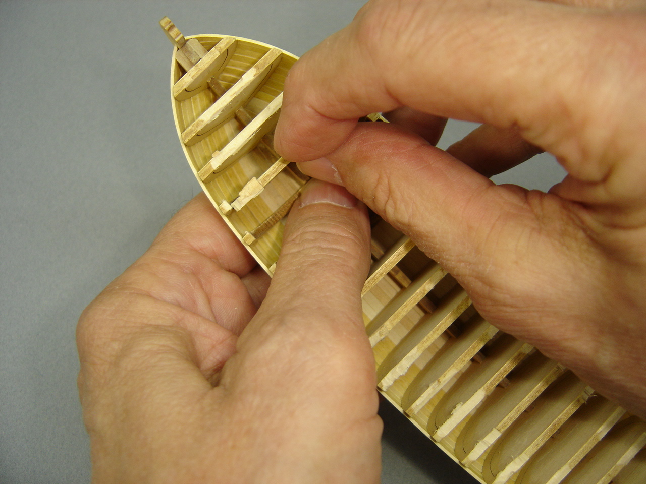
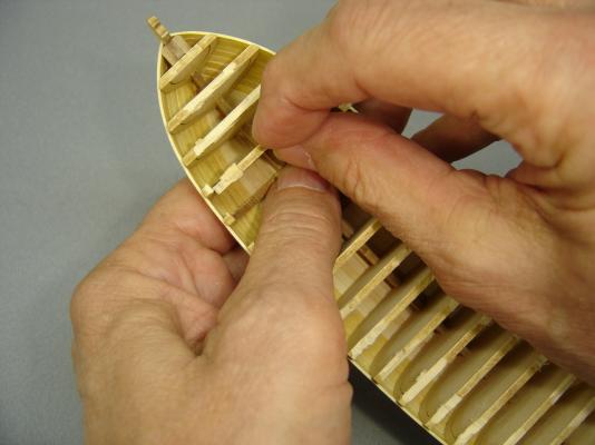
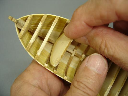
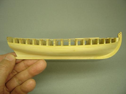
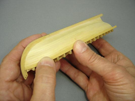
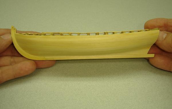
I have to admit that the bracing, which is being removed in the next two photos, served me well. There were times during the planking process when I put a lot of pressure on the hull, and the frame handled it. I decided to alternate port and starboard as I removed the bracing, just to make sure that no stresses were created. Removing the center portion of the bulkheads/frames was a snap. (No pun intended.) Chuck did a nice job with this design feature. I used a rather coarse file to get down to the laser cuts, which really didn't take long.

- 277 replies
-
- 8
-
-
- model shipways
- 18th century longboat
- (and 1 more)
-
Toni, The oars look great! I really enjoy that kind of innovative thinking. Little things like that set your model apart from the rest. Bob
-
Thanks, Geoff. I'm glad that you like it. Bob
-
David, I'm glad you like the photos. Because this is a group build project, I've been documenting my progress for our meetings. Anyway, I thought I'd post them on MSW as well. Bob
-
Chuck, Thanks for the kind words. As far as the stem is concerned, I came close once, but I just cracked it. I think it happened with about three planks to go, which really ticked me off! Hopefully, the hard part is over. Bob
- 277 replies
-
- 1
-
-
- model shipways
- 18th century longboat
- (and 1 more)
-
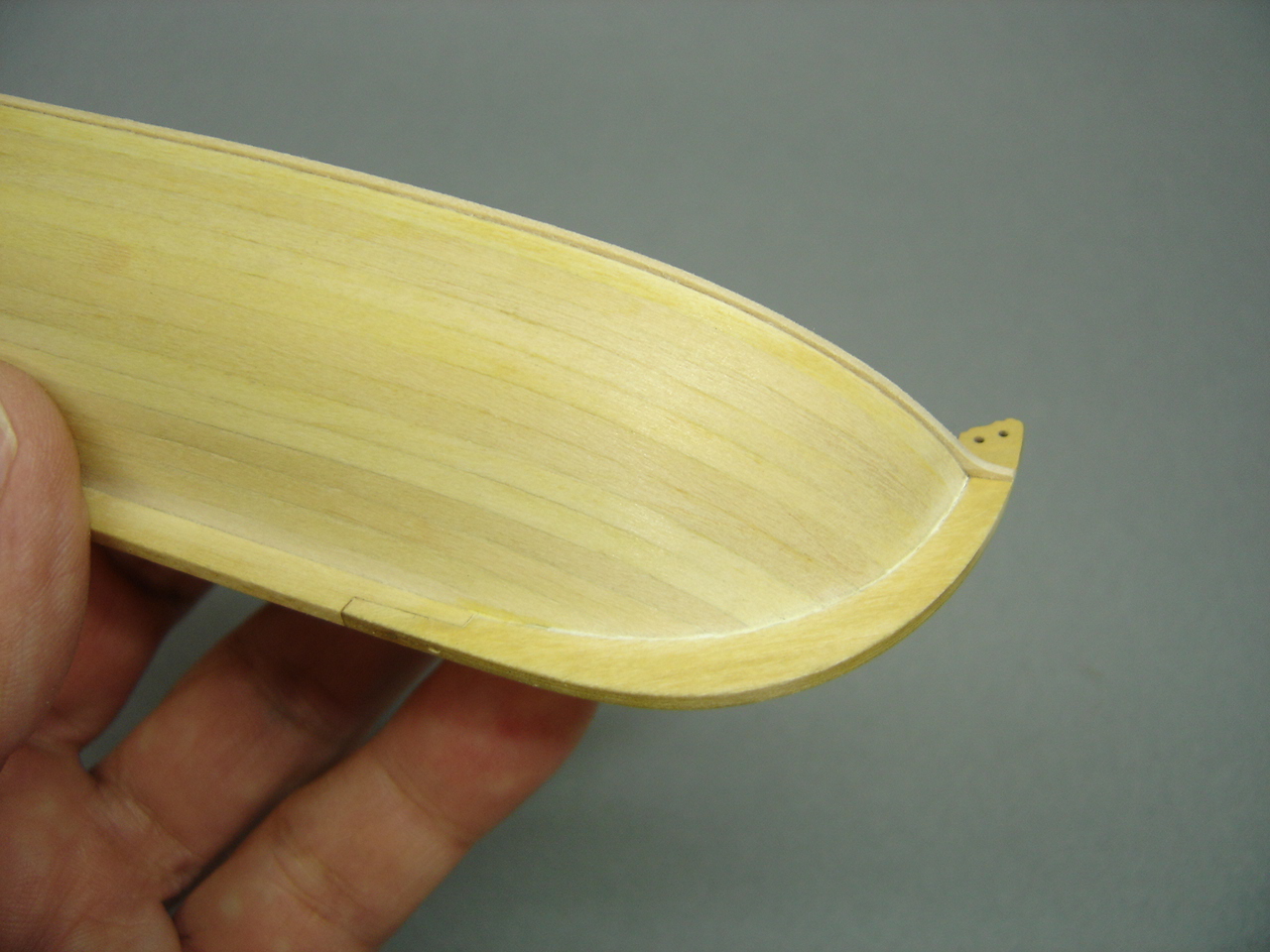
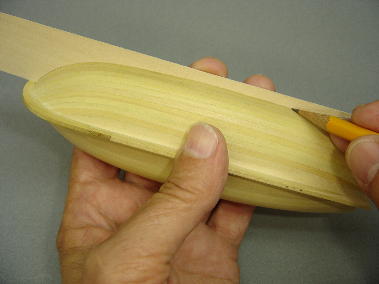
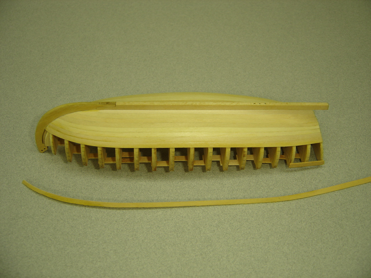
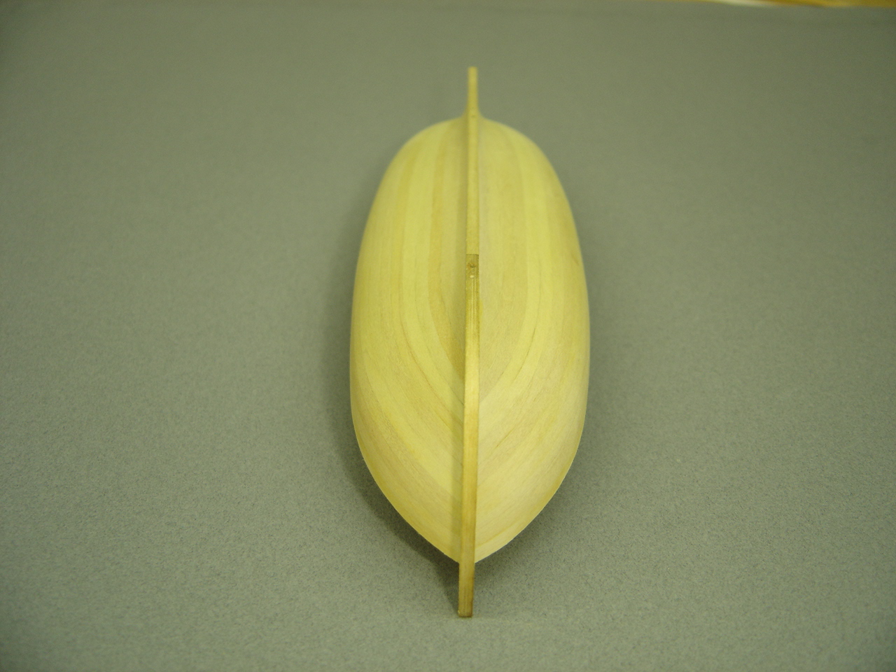
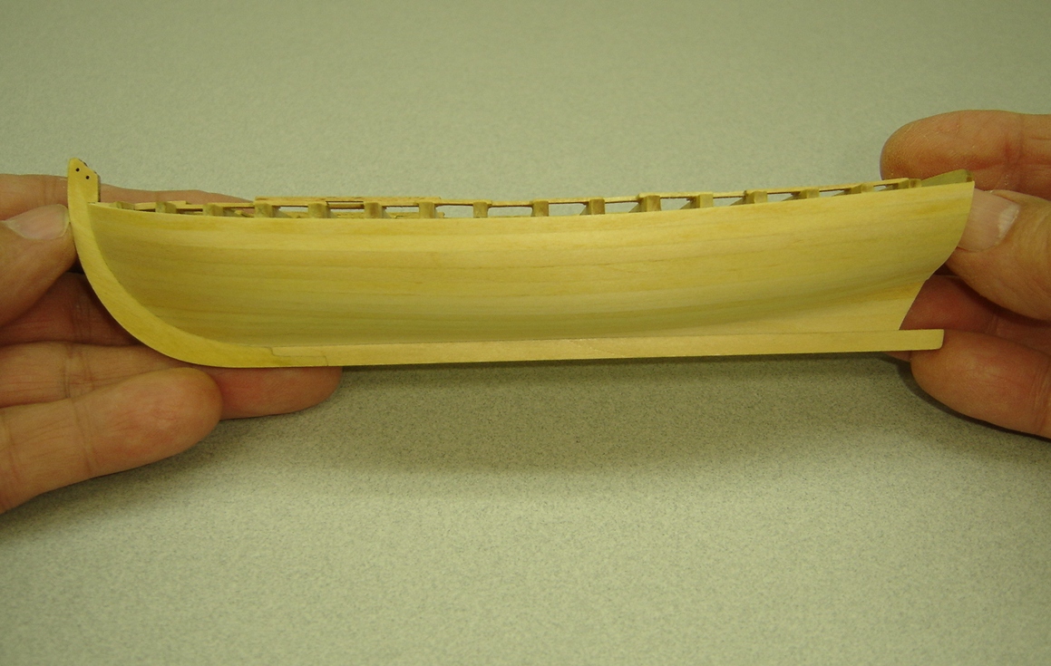
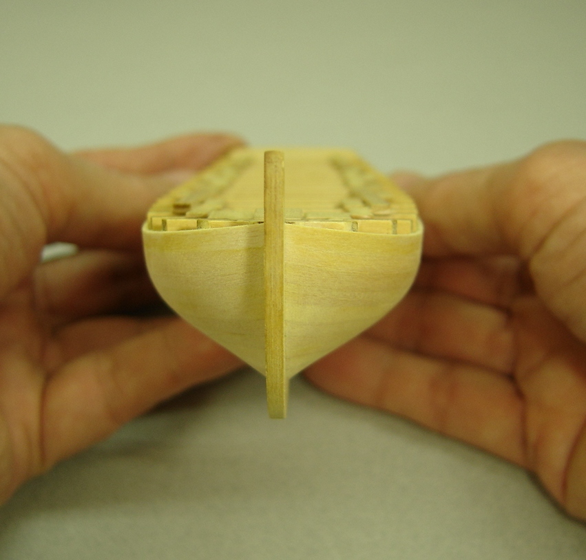
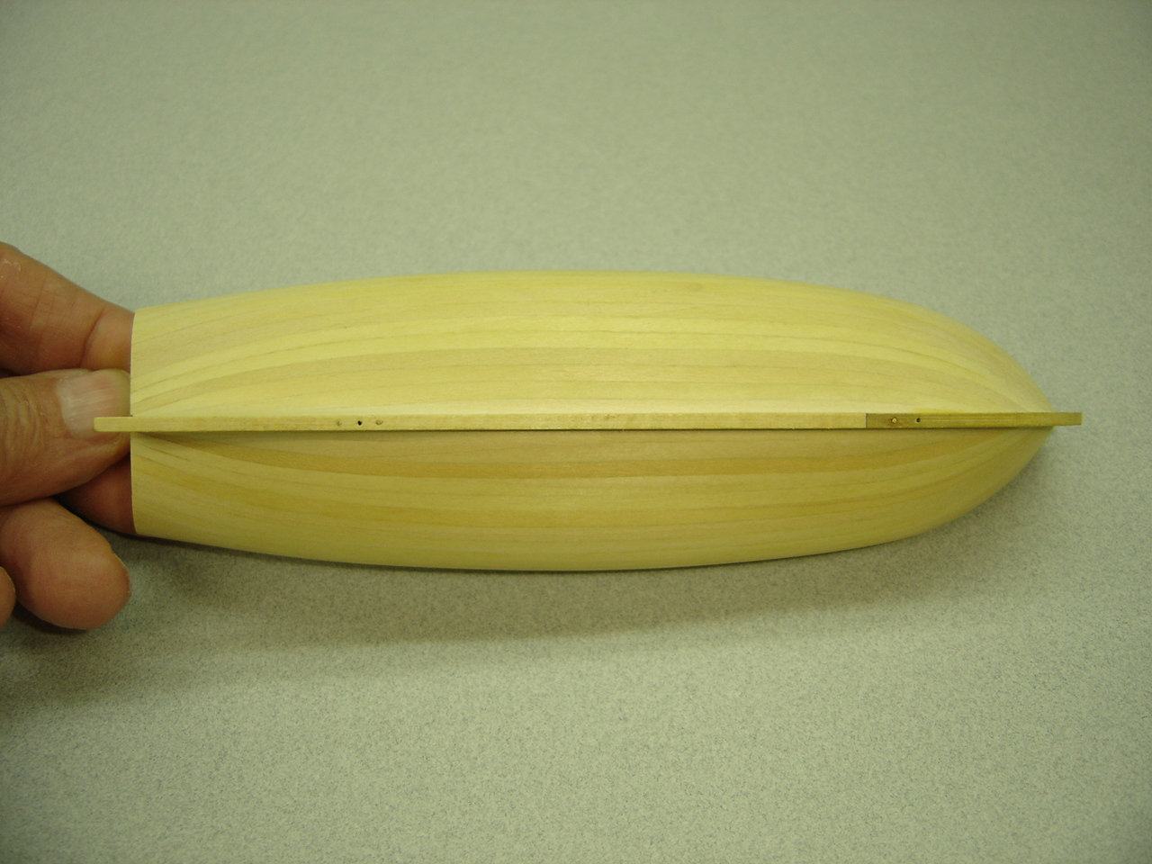
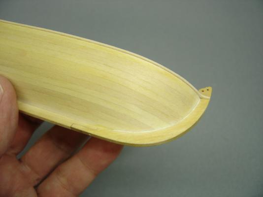
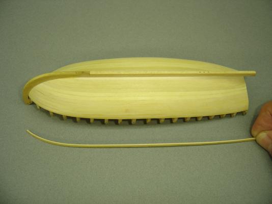
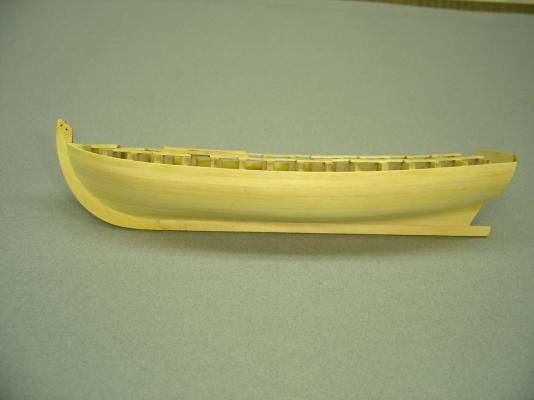
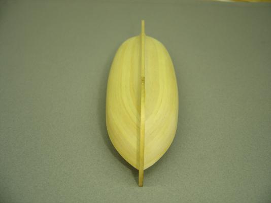
Hello all, Things have been a bit crazy for me lately, and I haven't had a lot of time to work on the longboat. However, since my last post, I did finish the planking, but I certainly didn't break any records! Here are a series of photos that show my progress. In this next photo, I have five planks left on each side, and I'm using the Magic Tape method to spile the planks. With only four planks to go on each side, the spiling is becoming noticeably easier. Whith only three planks to go, I stopped spiling and formed the planks by eye. At this point, because the curve of the planks wasn't that great, I was able to do a true edge-bend on the planks. As you can see in this next photo, the bend is not that great. There were only two left on each side at this point. In this photo, the next to last plank is being mounted. If I had to do it over again, I probably would have tapered the previous three or four planks a little bit more at the bow. Here are a series of photos of the completed planking job. This little hull has very pleasing lines,


- 277 replies
-
- 19
-
-
- model shipways
- 18th century longboat
- (and 1 more)
-
Jason, Although I've got a long way to go, I'm taking notes on your model. Your tips are paving the way for those of us bringing up the rear! Thank you. Bob
-
Toni - The model is looking really good. I especially like the natural wood color. If I could do it over, I would try to copy your technique. The color contrasts are very pleasing. Bob
-
Chuck - No, I don't do any tapering until the bends and twists have been made, and the spiled edge of the plank conforms to the edge of the plank already mounted. Often, that can require some shaping with a sanding block up forward where the plank sweeps around the mounted plank, and maybe a little at the stern. Most of the time, introducing a bevel is also necessary. Then the tapering starts, and the tick marks come into play. The outboard edge is sanded down until the tick marks become visible, which produces a properly proportioned plank. Not a lot of wood needs to be removed, and you have to constantly check, so as not to take too much off. If by chance you do take a little too much off, you probably can make it up with the next plank or two being a little wider. It probably won't be noticeable. I hope my explanation makes sense. Please don't hesitate to contact me, if you have any questions. Bob
- 277 replies
-
- 2
-
-
- model shipways
- 18th century longboat
- (and 1 more)
-
Wacko ( I really feel strange calling you that. ) I'm really glad that I could be of some help. Although I understand the concept of spiling, I have to admit that this little model has been a learning experience for me as well. Bob
-
Chuck - I'll definitely try it with my next model. This is going to make my club spiling presentation obsolete! That's OK though, it was really too long to begin with. Bob
- 277 replies
-
- 1
-
-
- model shipways
- 18th century longboat
- (and 1 more)