HOLIDAY DONATION DRIVE - SUPPORT MSW - DO YOUR PART TO KEEP THIS GREAT FORUM GOING! (Only 24 donations so far out of 49,000 members - C'mon guys!)
×


BobF
-
Posts
175 -
Joined
-
Last visited
Content Type
Profiles
Forums
Gallery
Events
Everything posted by BobF
-
 Thanks, Bob. One thing I failed to mention in my last post is the fact that increasing the height of the transom is going to impact how the white trim around the frieze looks. I haven't figured that one out yet. I guess I'll cross that bridge when I get to it. BobF
 -
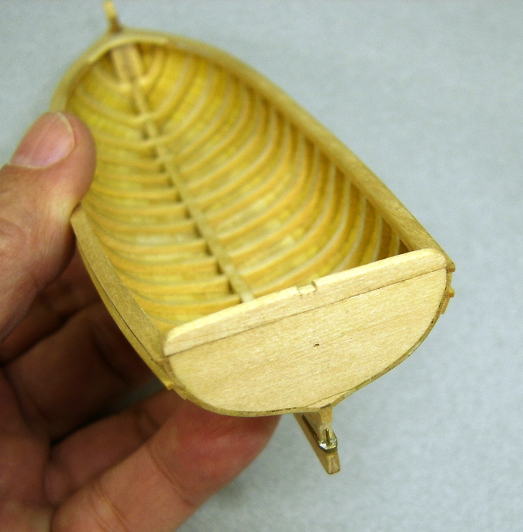
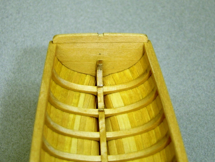
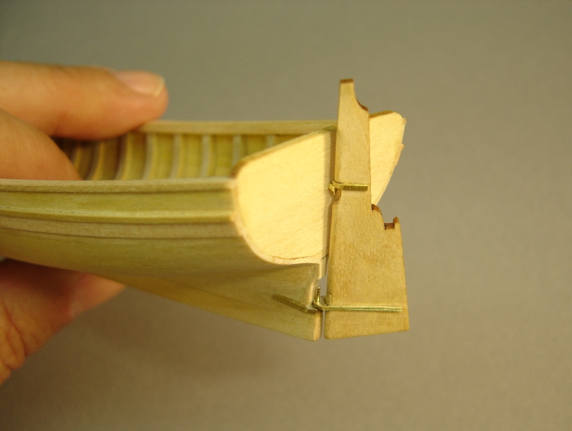
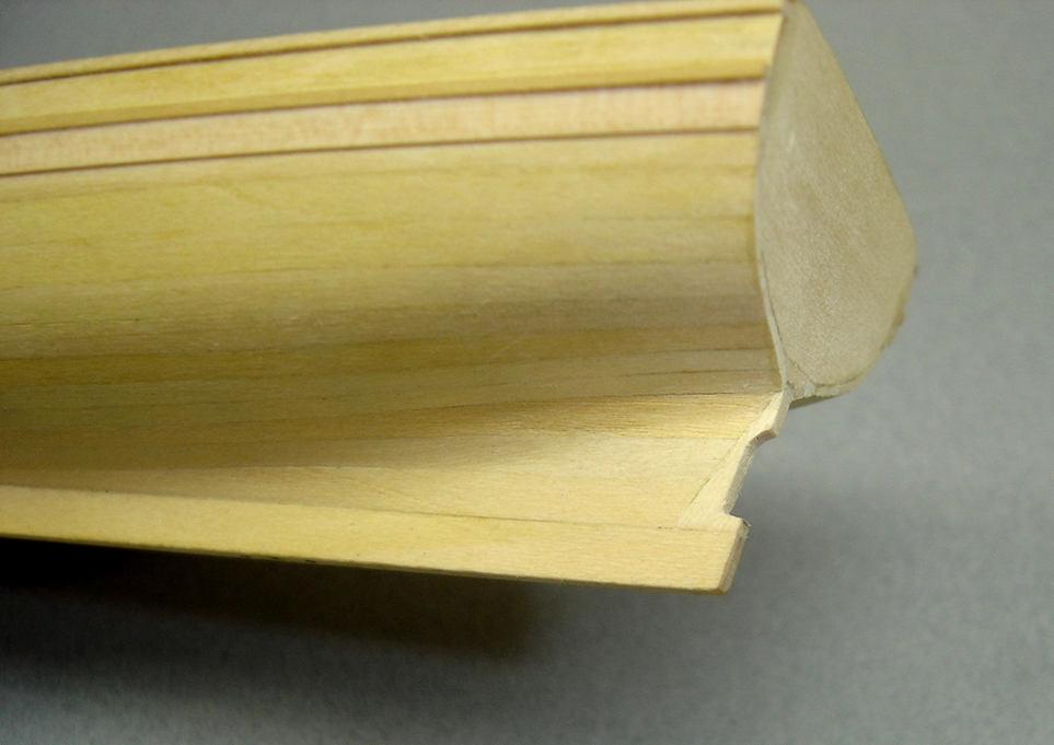
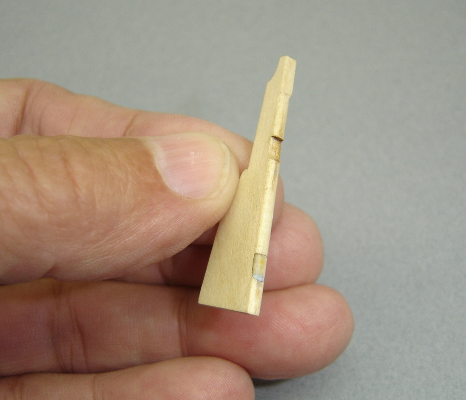
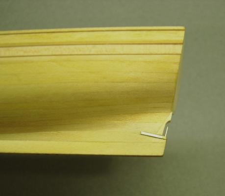
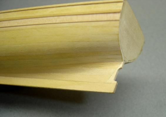
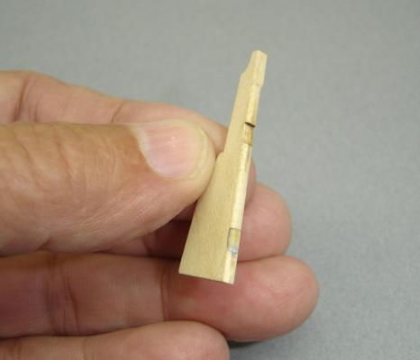
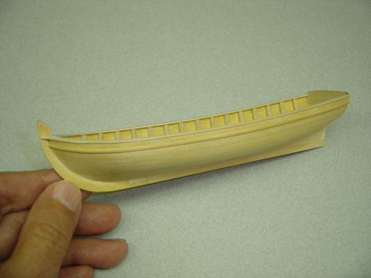
As stated earlier, I'm trying to duplicate some of the features that are shown on the NMM models. Although my model won't have an anchor davit off the stern, I still want to show the features that would be required if one were used. I realized that my transom wasn't high enough, and if a davit were mounted, the horse would be in the way. So, I sanded down the top of the transom, flush with the cap rail, and mounted a slightly higher piece. In the photos, the notch that the davit would sit in has been started, and will probably be cut a little deeper. BobF

- 277 replies
-
- 10
-

-
- model shipways
- 18th century longboat
- (and 1 more)
-
Hi David, Your technique appears to be improving as you get deeper into this model. Keep up the excellent work! Regards, BobF
-
Hi Mike, It looks to me like you are doing everything correctly. As near as I can tell, the only difference between our two models is the fact that I proportioned all the planks from the keel up to, and including, the sheer plank. It wasn't necessarily the right way, it was just the way I opted to do it. I see in your log that Chuck suggested that you taper the plank under the sheer strake, which is very good advice. Also, leaving the sheer strake full size will work out better when you apply the frieze strip. If the planks between the waterline and the molding strip located under the sheer plank are left natural, you'll have very pleasing plank runs. I see that you are using the tick marks, which should give you an accurate indication as to how wide the planks will be. However, as you terminate a plank at the rabbet, you will have to reduce the plank count by one, and reproportion the area at the bow that's left. It sounds like that's what you have been doing. I would suggest that you do not let those first and second broadstrakes, located above the garboard strake, go too far forward. That's one of the keys to having more room at the bow for the rest of the planks. I've always used a rule of thumb when planking that a plank should not taper more than half of its original width. Since you stated that it's "close" to 1/16", that sounds OK. I hope all this helps. If not, drop me a line, and good luck! BobF
- 277 replies
-
- 1
-
-
- model shipways
- 18th century longboat
- (and 1 more)
-
Hi Mike, The next three or four planks after the garboard strake can be problematic. You can edge bend them only so far. If you study some of the photos in sections 2 and 3 of my log, you'll see a distinct curve right at the forward end of the plank that's being mounted. That was created by sanding the inside edge of the plank. You're most likely going to have to taper these planks slightly, so don't worry about removing a little material. On this model, I did not proportion a plank until after I had that inside edge where I wanted it. It's probably going to take some twisting and bending the normal way to get the plank to lay right at the rabbet once you've introduced that curve. One more thing: When you create that curve, you're going to have to continue lightly sanding some distance going aft so that you have a nice transition along that edge.. I hope I've explained myself properly. If not, don't hesitate to contact me. BobF
- 277 replies
-
- 2
-
-
- model shipways
- 18th century longboat
- (and 1 more)
-
Congratulations, Dan. Very nice job! The experience you gained planking this little model will pay dividends on your next project. See you at the meeting. BobF
-
Clare, I haven't had time to work on the model lately. I've got to be one of the slowest modelers on this planet! Anyway, thanks for the kind words. I really like the way your model is progressing. Very nice job! BobF
-
I'm glad that you like it so far. I stopped working on another project, so that I could join the Tri-Club group build. When I get back to the other model, I may apply the planking techniques that I learned with the long boat. There are definite advantages to edge bending planks, if the wood you are using will cooperate! I'm certainly going to give it a try. BobF
-
Thanks for the kind words. This little model has presented me with opportunities to try some different things, which has made building it a lot more fun. BobF
-
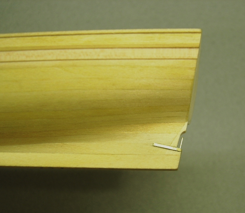
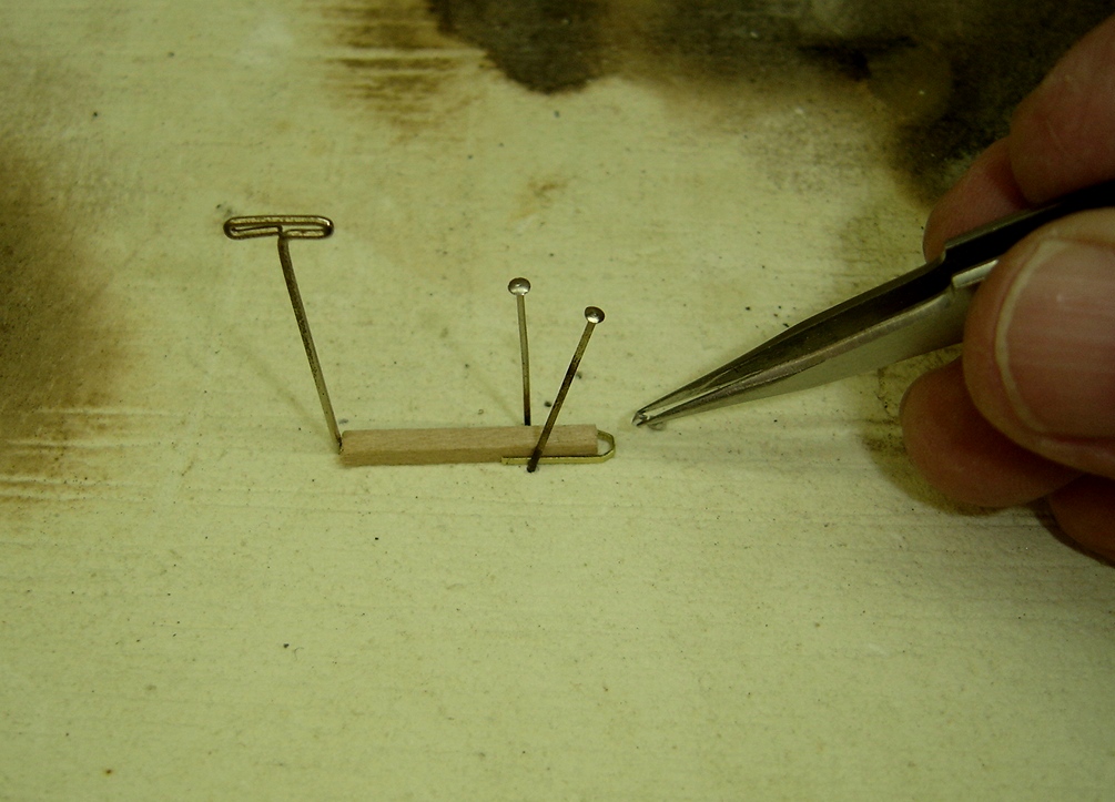
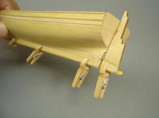
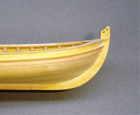
I used 5 minute epoxy to glue the gudgeons and pintles in place. Although a little messy, this usually gives me plenty of time to get the pieces lined up properly, and remove the excess adhesive. I always start out with the lower pintle, which in this case, was attached to the stern post. In order to properly line up the lower gudgeon, I used some miniature clamps, and a strip of L-shaped basswood, which kept the bottom of the rudder lined up with the bottom of the keel. This worked really well. I decided to find the proper location for the upper gudgeon before I painted the model and attached the transom frieze. In the photo the gudgeon is only press-fitted in place. I don't think it'll be a problem relocating it later on ... at least I hope not! BobF

- 277 replies
-
- 11
-
-
- model shipways
- 18th century longboat
- (and 1 more)
-
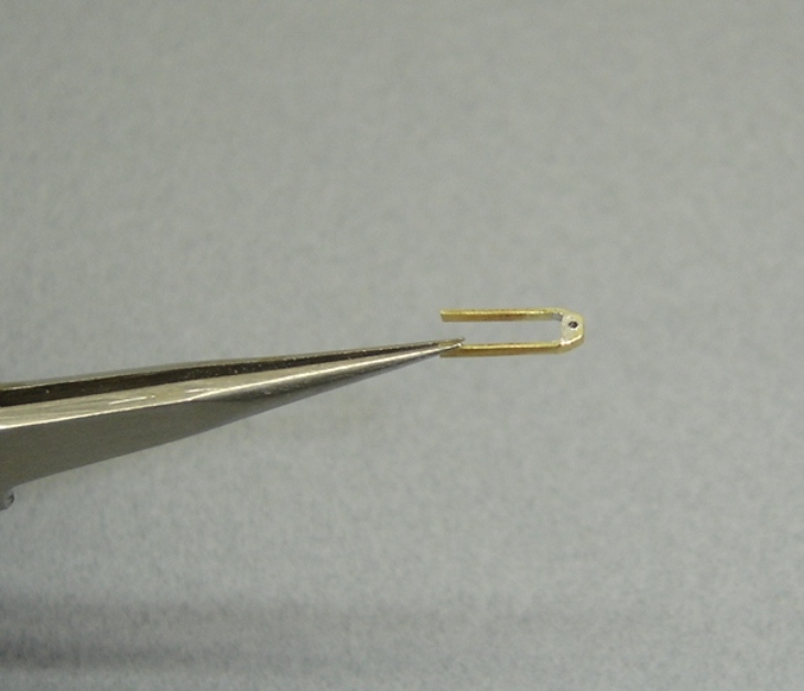
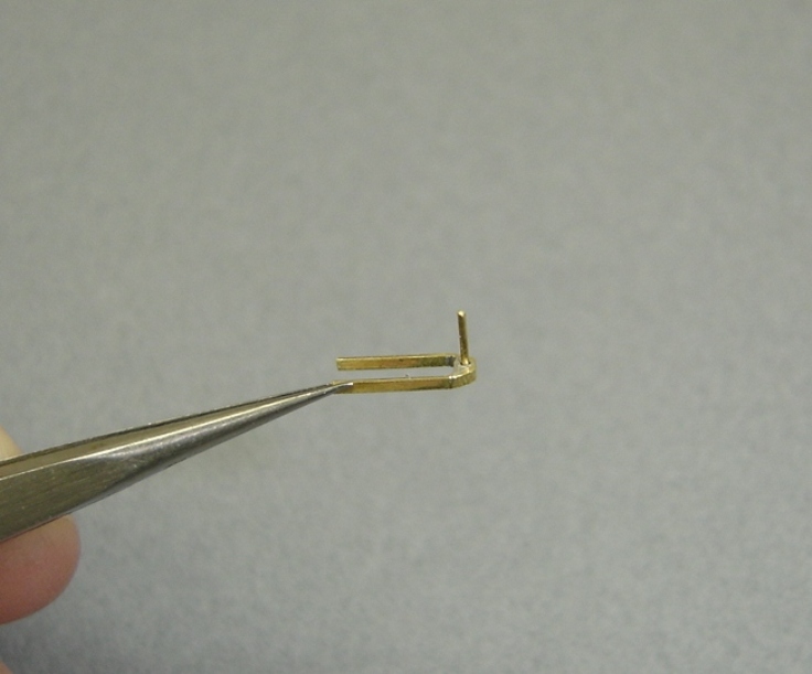
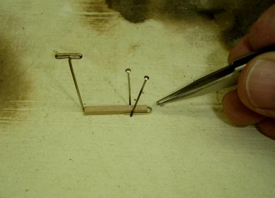
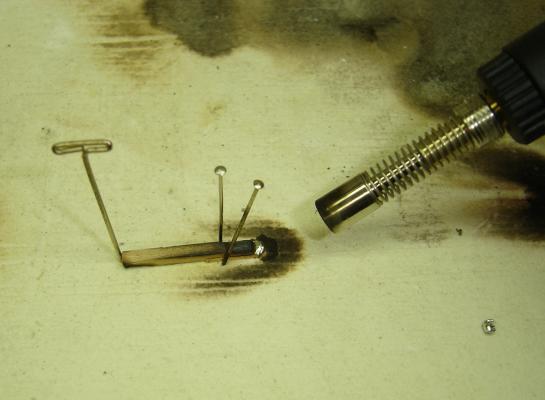
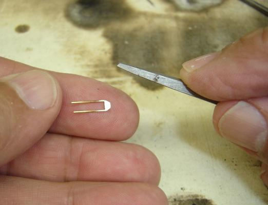
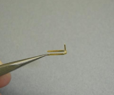
I wanted to have the lower gudgeon and pintle assembly in place before I painted the model. I decided on a technique that I had never used before. I may have "re-invented the wheel," but for me it was something new. After removing the temper and oxidation from a strip of brass that was supplied with the kit, I bent it into the desired shape. After applying some flux to the piece, I placed a strip of "sacrificial" wood in position, so that it would act as a dam. Small bits of Stay-Brite solder were then placed inside the area and heated with a micro torch. When the Stay-Brite melted, it had a tendency to bead up, and not completely fill the area. I took a flat tool, and compressed the hot solder, forcing it to fill the void. I then filed away the residue, and shaped the piece. For the pintles, I opted to epoxy the pin in place, rather than include it in the soldering process. I just felt that it would be a lot easier to file down the piece to its correct shape if the pin was installed afterwards. For me, the hardest part of this procedure was getting the brass strips shaped exactly the way I wanted them, so they would fit properly around the stern post and rudder. The rest of the technique was pretty straight forward. BobF

- 277 replies
-
- 18
-
-
- model shipways
- 18th century longboat
- (and 1 more)
-
Chuck, I agree. Locating the horse under the tiller bar was probably considered "The Lesser of Two Weevils." (I couldn't resist writing that. ) BobF
-
I have a theory about the location of the horse on these boats. If someone else has already mentioned this, I apologize for missing it. It has to do with the fact that long boats were used to help retrieve a ship's anchor when the vessels were getting underway. This required the use of an anchor davit that was rigged over the stern. If the horse was located above the tiller bar, it would have impeded the use of this davit. If you look closely at Chuck's photos, you can see a notch in the transom, where the davit would have been mounted when being used. One of my reference books states that these long boats were designed to do many tasks, and, as a result, they did not do any of them well. Captains, supposedly, did not like these craft. The horse arrangement may have been one of the reasons. BobF
-
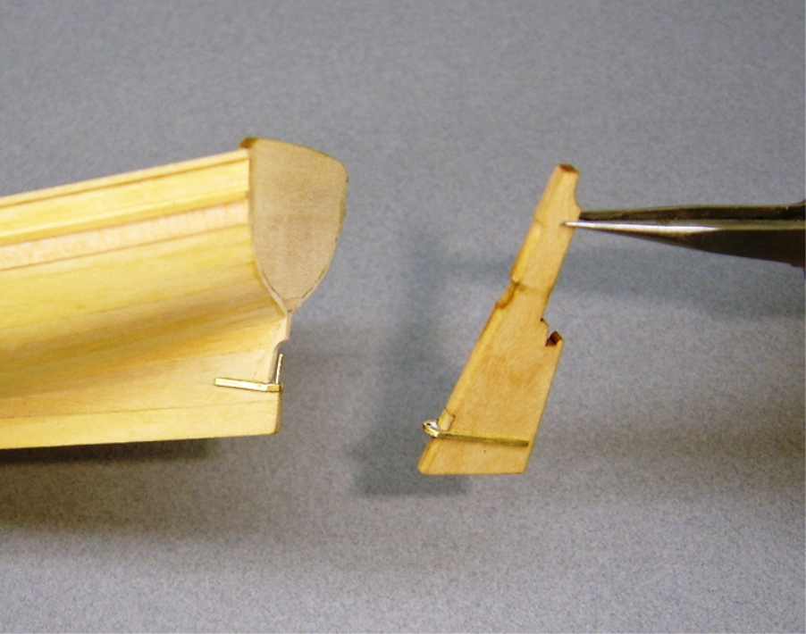
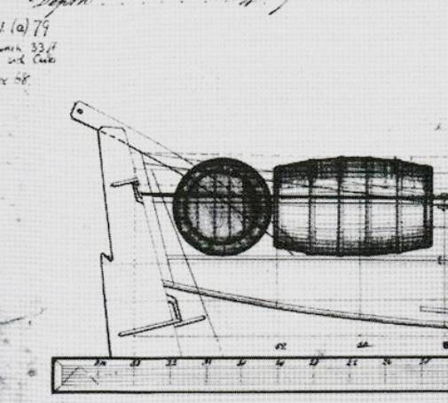
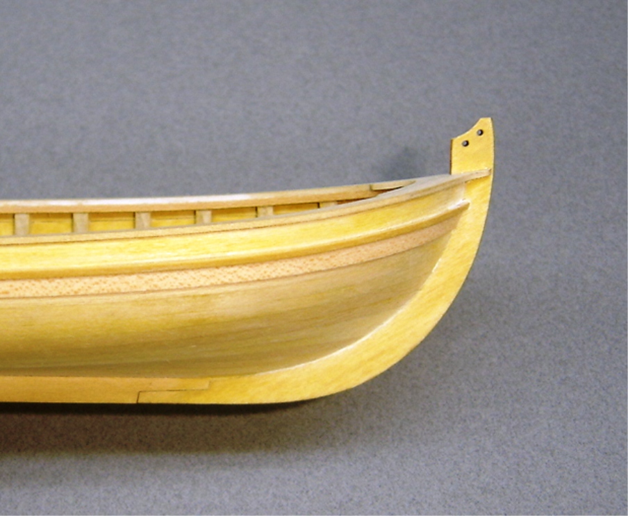
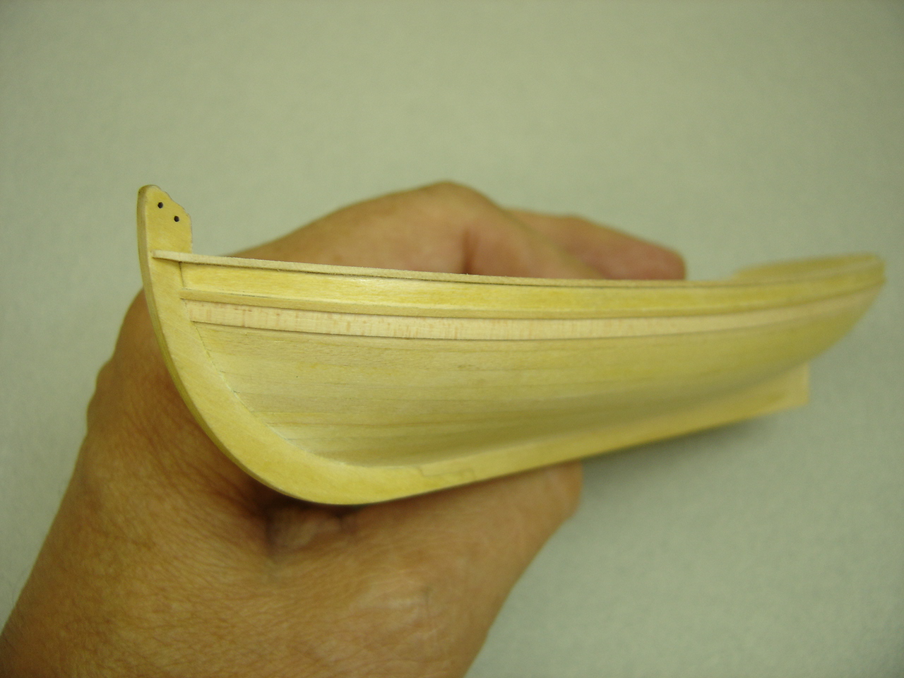
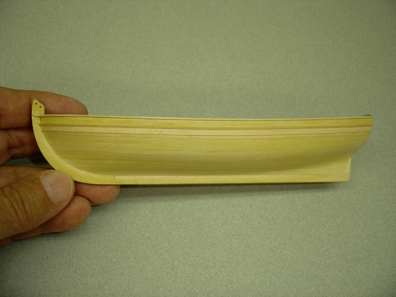
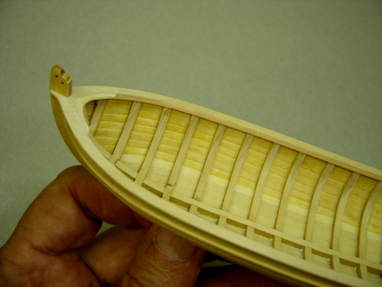
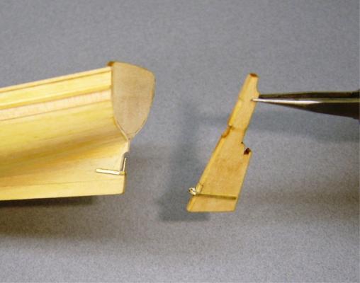
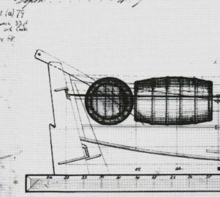
The photos of the long boats in the National Maritime Museum continue to influence my building of this model. Apparently, It was quite common for the gudgeon/pintle arrangement on these craft to differ from other vessels. The lower pintles were fastened to the stern post, and the upper pintles were attached to the rudder in the conventional manner. Attached, is a portion of a drawing of a similar boat from the same period. Modifying the location of the lower pintle was no more difficult than if it hand been mounted on the rudder. The only extra work involved cutting out the recess in the stern post, and filling in the same area in the rudder. At the bow, I decided to modify the upper portion of the stem. Again, the NMM photos were the reason, although I like the appearance of the stem as featured in the kit.
- 277 replies
-
- 8
-
-
- model shipways
- 18th century longboat
- (and 1 more)
-
Hi Dan, In a situation where you need to make a minor bend in the conventional manner, it's possible to do so without wetting the plank, especially 1/32" basswood. Just don't hold it over the iron too long. Also, sometimes I'll just wet the area that needs bending with a little water off my finger. Either procedure will have less impact on your edge bend. I also discovered the hard way that resoaking a plank can allow it to lose some of its bend, if it's not clamped down. What you have accomplished so far is looking very good. BobF
-
Dan: I know a modeler who planks his hulls using tables very similar to your's, and they turn out awesome! The method you will be using can be very precise. I think you're on the right track. BobF
-
Thanks to all of you for your kind words. I have to admit that I enjoy kit building a lot more when I can make modifications to the model that are historically correct. I seem to get more motivation, and the model then possesses some unique qualities. The photos of the NMM models possess quite a few little differences that are fascinating, and, in some cases, puzzling. For me, that's what makes it fun. BobF
-
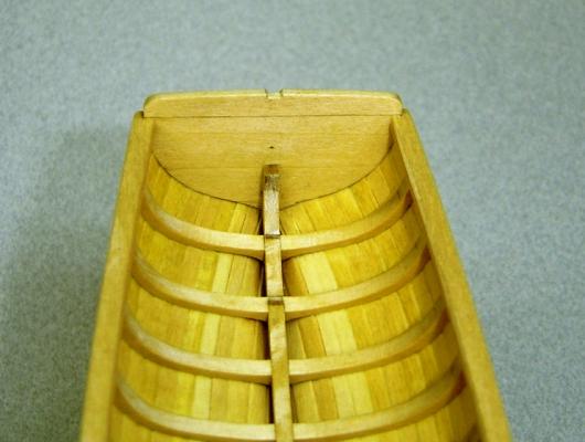
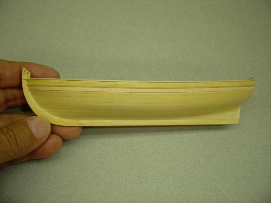
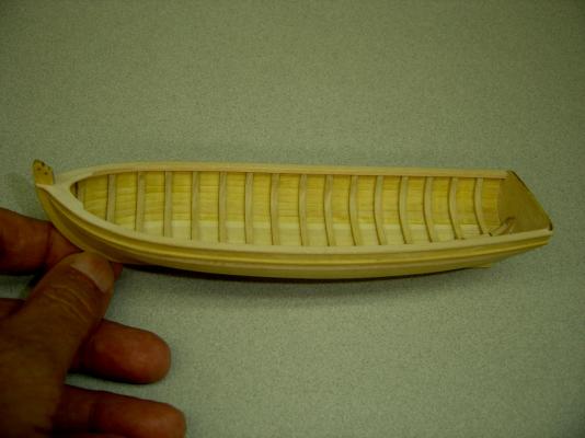
Originally, I stated that painting was next, but I reconsidered. After studying some photos of contemporary long boat models at the National Maritime Museum, I decided to make some small changes on my model. The first involved the addition of a thin plank under the molding strip. These thicker planks may have been there to provide additional strength for mounting the chain plates. The wood I used was dogwood. It is similar to boxwood, but is very flexible, which was a plus in this case. The markings the wood possesses are not a problem, since the plank will be painted. Two other changes involved the addition of strips under the caprail on the inboard side, and the breast hook being attached so that it is flush with the top of the caprail. In the kit it is mounted under the caprail. In the kit, the staysail halyard block is attached to the breast hook. On the NMM models this block is attached to the apron located under the breast hook, which is what I intend to do.


- 277 replies
-
- 12
-
-
- model shipways
- 18th century longboat
- (and 1 more)
-
Barrels
BobF replied to ross's topic in Discussion for a Ship's Deck Furniture, Guns, boats and other Fittings
Hi Ross, Saw your inquiry concerning scuttlebutts, so I thought I'd post a photo of one that I mounted on a Pinky. Hope it helps. BobF
-
Thanks Paddy. Next, is the paint job, which will make or break this model. Wish me luck. BobF
-
Paddy, I'm sorry, but I can't take credit for the building boards. They were constructed (17 of them I think) by another Tri-Club member, Kurt V. The building board was indispensable while gluing the bulkhead/frames to the false keel. It's time well spent building one. BobF
-
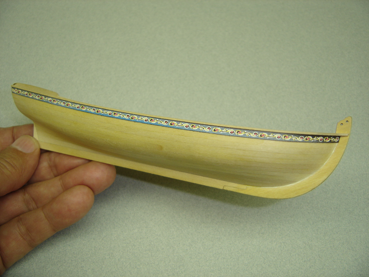
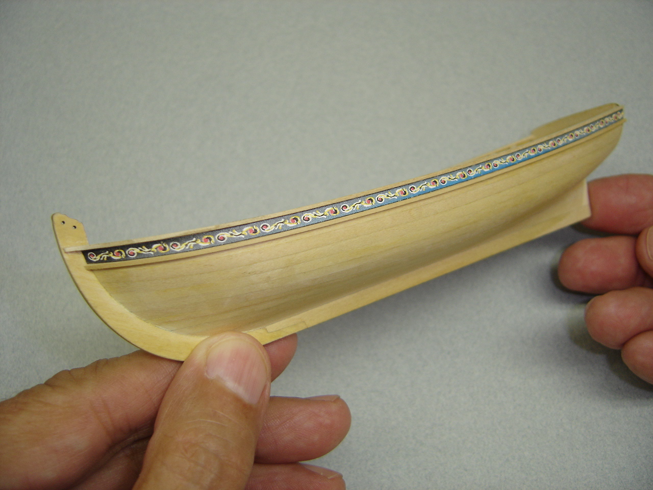
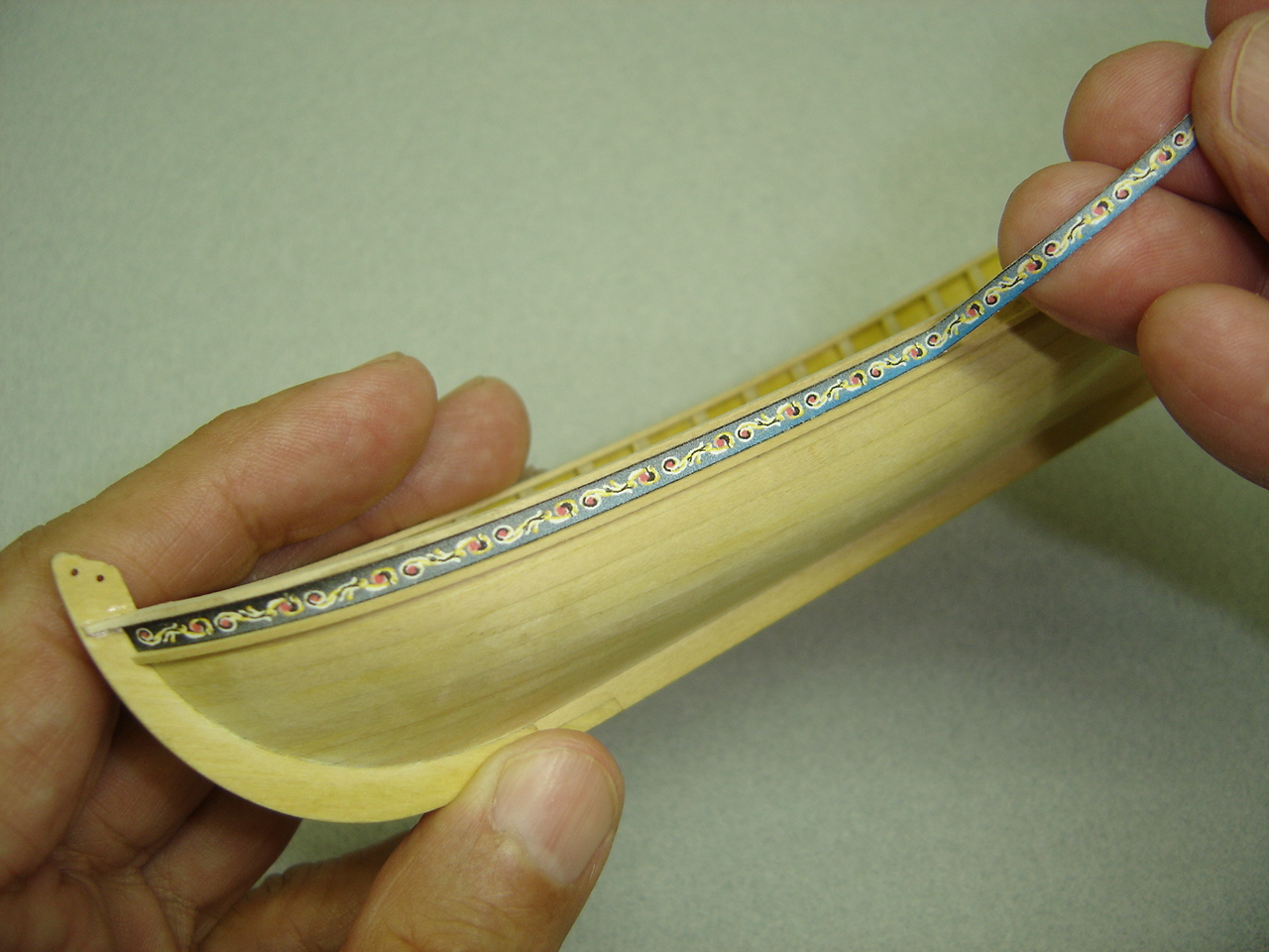
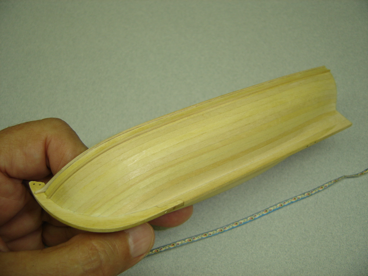
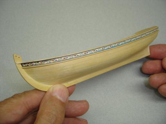
You might say that I've been in the Summer Doldrums, although mine sometimes extend well into November or December! Anyway, it's been a while since I posted anything, so here is what I've accomplished, as minimal as it might be. I've decided to try something a little different as far as the molding strip is concerned. I glued a copy of the frieze on to the hull with rubber cement, so it could be removed after the molding strip is glued on. I intend to airbrush the painted surfaces of the model, so, hopefully, I'll have clean, crisp lines between the different colors when I'm finished. Since I'm using Elmer's white glue, I can also make minor adjustments to the molding strip if there is any deviation in the run. The down side to all this will be getting the friezes to fit properly when it's time to glue them on. Stay tuned, mates.


- 277 replies
-
- 12
-
-
- model shipways
- 18th century longboat
- (and 1 more)
-
Dan, I glued strips across the tops of the bulkheads, which worked well. At times, I put a lot of stress on the frame while applying planks, and I didn't experience any distortion. Your model is looking good, mate! BobF
- 175 replies
-
- 1
-
-
- 18th century longboat
- model shipways
- (and 1 more)
-
Chuck - I also thought about using a strip of plastic for the lower molding, but decided against it. I'll stick with wood. Bob
-
Bob - Your paint job looks great. I originally planned to stay with the wood supplied in the kit, but after seeing your results, I think I'll switch to a harder wood for the risers and seats. Nice job! BobF