HOLIDAY DONATION DRIVE - SUPPORT MSW - DO YOUR PART TO KEEP THIS GREAT FORUM GOING! (Only 24 donations so far out of 49,000 members - C'mon guys!)
×


BobF
-
Posts
175 -
Joined
-
Last visited
Content Type
Profiles
Forums
Gallery
Events
Everything posted by BobF
-
 Hi Jon, The article is featured under "Shipwright's Apprentice," pages 82 - 86 The entire piece is devoted to making oars. Hope that helps. Bob
- 277 replies
-
- 2
-

-
- model shipways
- 18th century longboat
- (and 1 more)
-
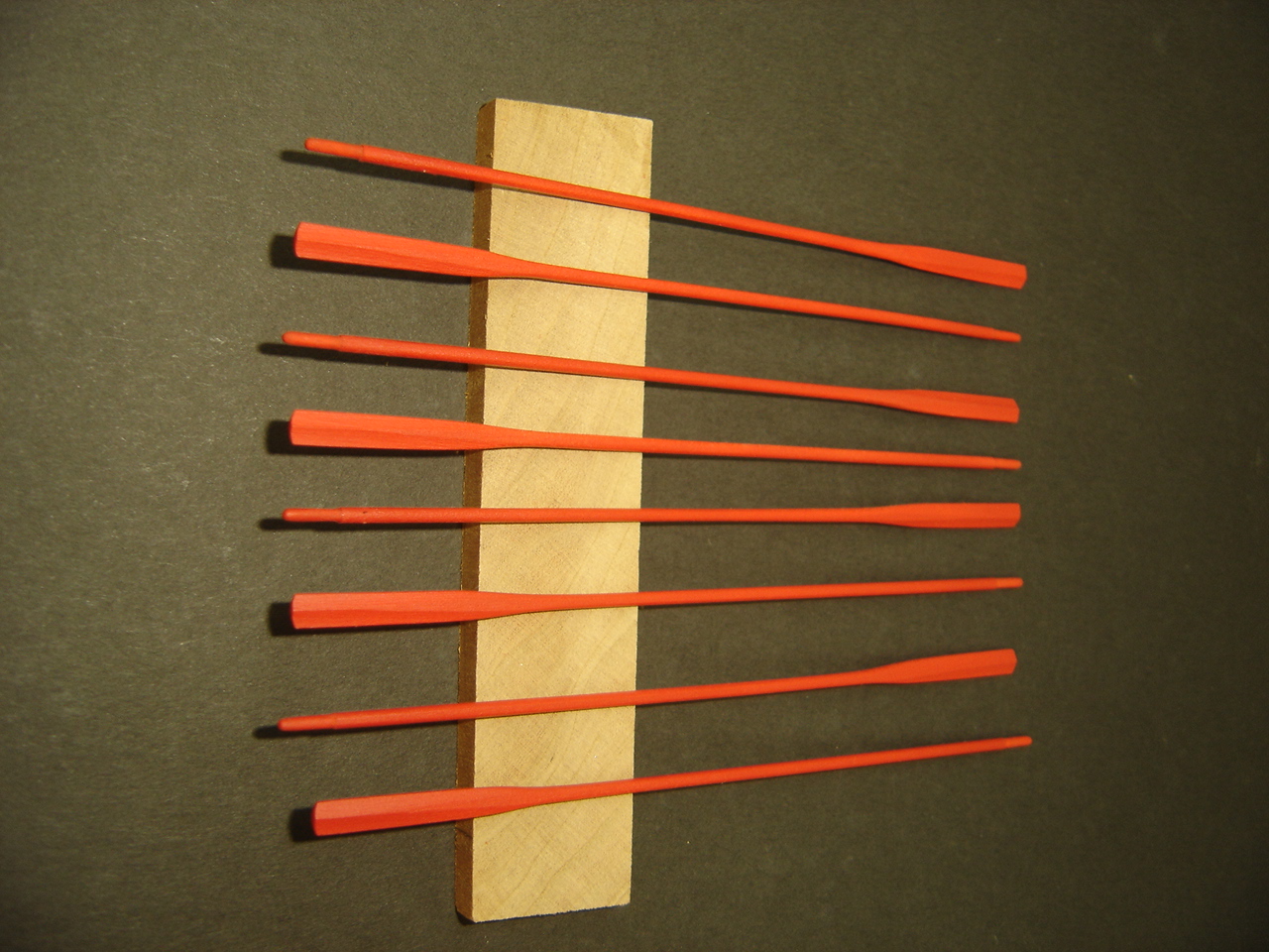
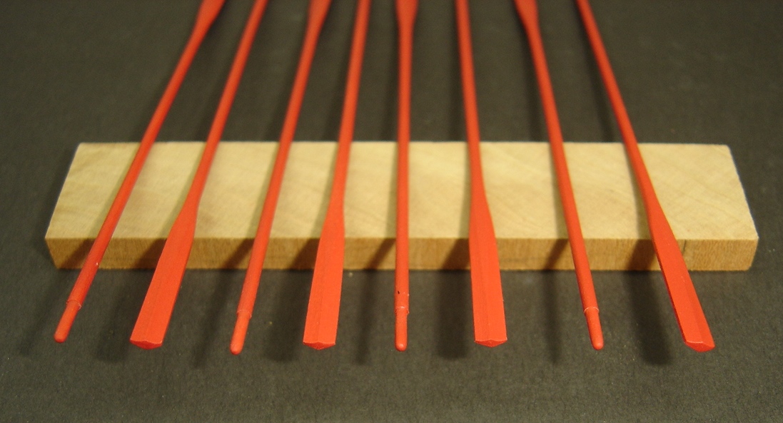
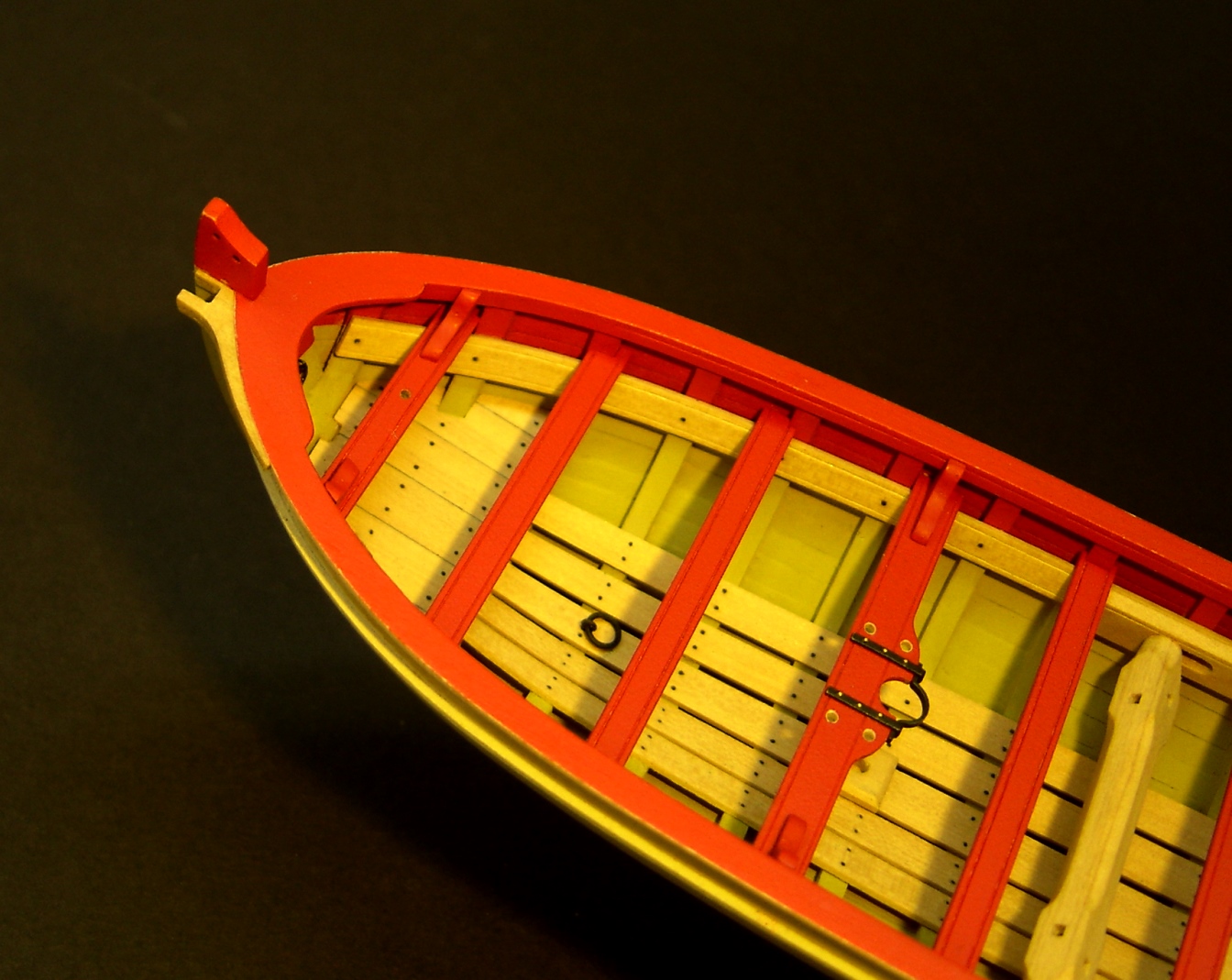
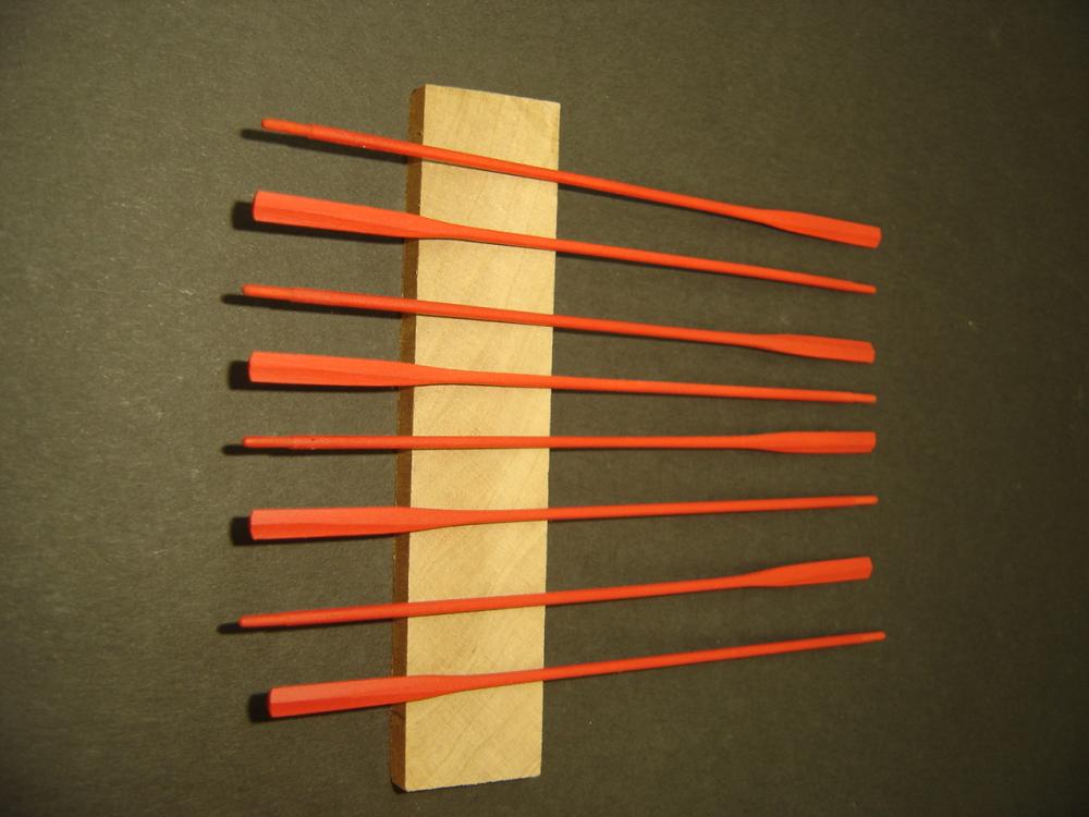
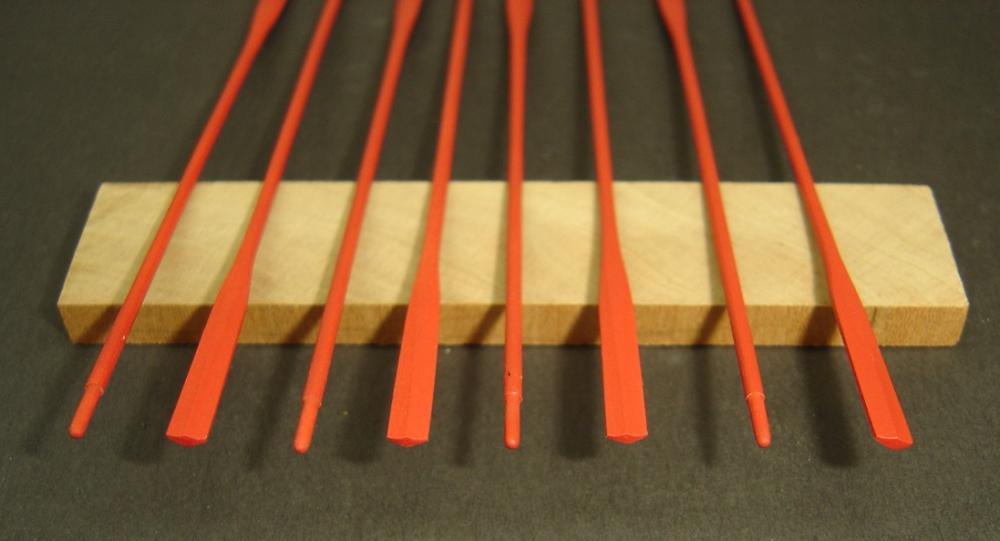
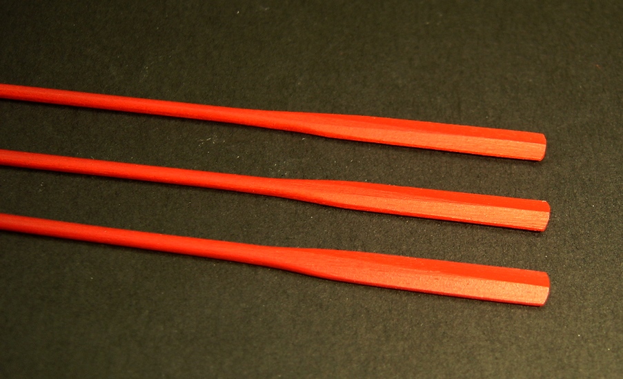
Mike: Although not the best quality, here are a few photos of the completed oars. I used a technique described by Steve Wheeler in the January/February 2009 issue of Ships in Scale. Based on contemporary long boat models, I decided to paint the oars completely red. BobF
- 277 replies
-
- 10
-
-
- model shipways
- 18th century longboat
- (and 1 more)
-
Hi Mike, The model hasn't changed much since my last post. When I have worked on it, I've been concentrating on items off the model such as the oars and the case. I wanted to have the case ready to go when the model is finished. The case base has some features you might find interesting. I'll try to post some photos soon. Thanks for your inquiry. Regards, BobF
- 277 replies
-
- 4
-
-
- model shipways
- 18th century longboat
- (and 1 more)
-
Hi Elijah, Met you at the NRMS meeting last night, and I was very impressed with you, and your accomplishments so far. The Phantom kit makes a handsome model, and with your desire to learn and methodical approach, it's going to be a real beauty! I look forward to seeing your future progress at club meetings, as well as on MSW. BobF
- 701 replies
-
- 2
-
-
- phantom
- model shipways
- (and 1 more)
-
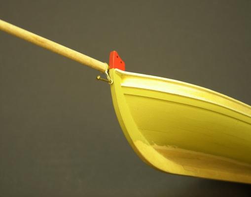
Thanks, Toni. I have to admit that I was already having second thoughts. I noticed this odd fitting at the bow. What could it be for? Hmmmm. I wonder if there is a support group for addicted kit bashers? BobF
- 277 replies
-
- 3
-
-
- model shipways
- 18th century longboat
- (and 1 more)
-
Erik, Thanks, but I'll tell you a secret. I keep the camera slightly out of focus. That hides a lot of flaws. The bow modifications will be the last kit bashing I do on this model. I get a lot of grief from my fellow club members about how long I've been working on this longboat. It's definitely time to get it in a case! BobF
- 277 replies
-
- 4
-
-
- model shipways
- 18th century longboat
- (and 1 more)
-
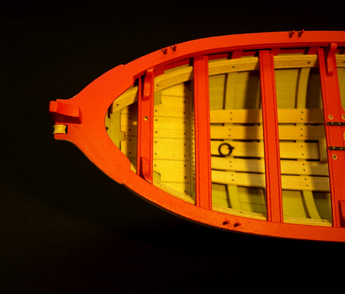
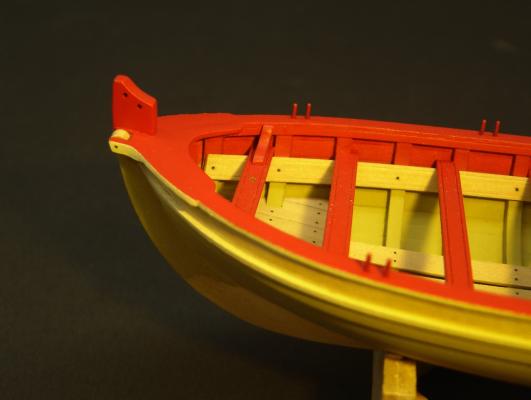
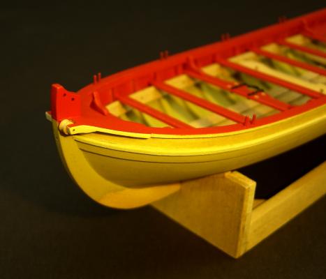
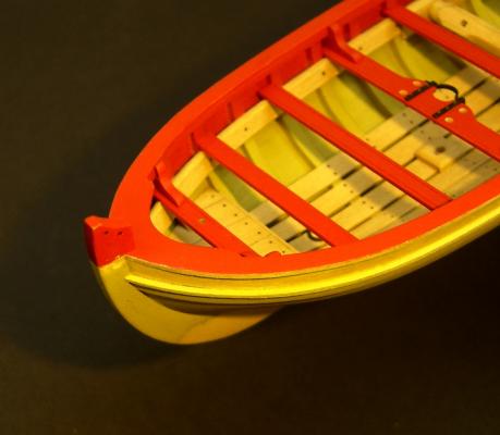
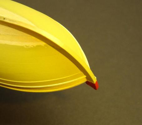
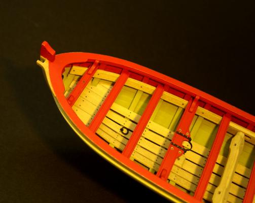
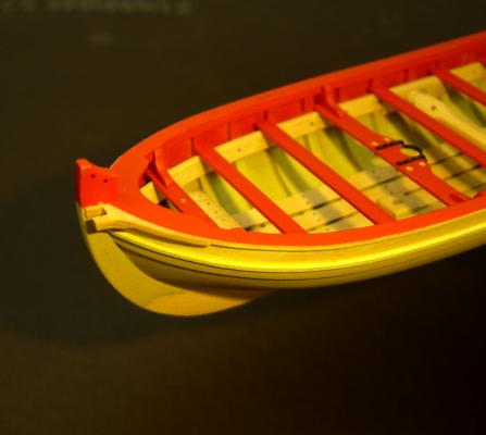
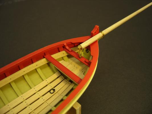
Here are a few photos of the modified bow. The thole pins have also been installed. For the pins, I used small quantities of five minute epoxy to glue them in place. This gave me time to align them and make sure they were at a uniform height. BobF

- 277 replies
-
- 16
-
-
- model shipways
- 18th century longboat
- (and 1 more)
-
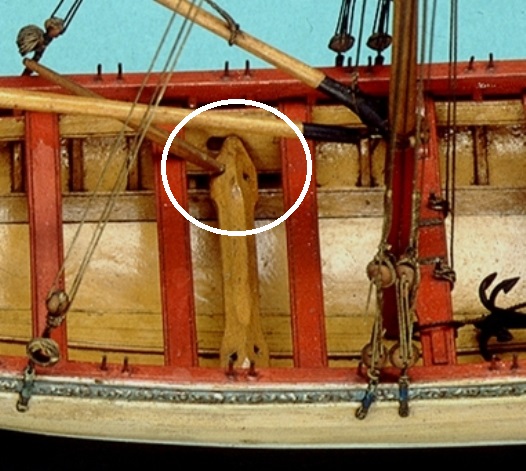
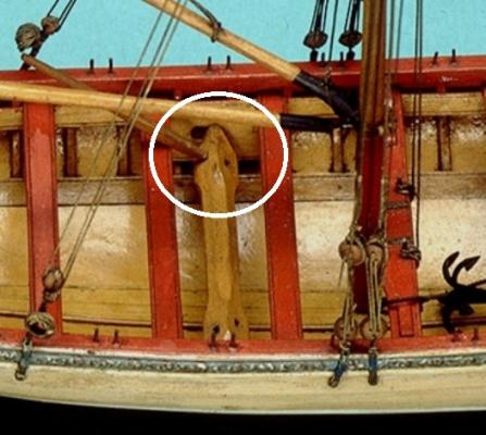
JS: If you go back to my post #178, you'll see a photo of a contemporary model that happens to have the pulley at the bow. Although not quite as clear, you can also see that the starboard side seems to have the same shaped piece with no pulley. Could it have been for the sake of symmetry, or did it provide additional support for the bowsprit? BobF
- 277 replies
-
- 3
-
-
- model shipways
- 18th century longboat
- (and 1 more)
-
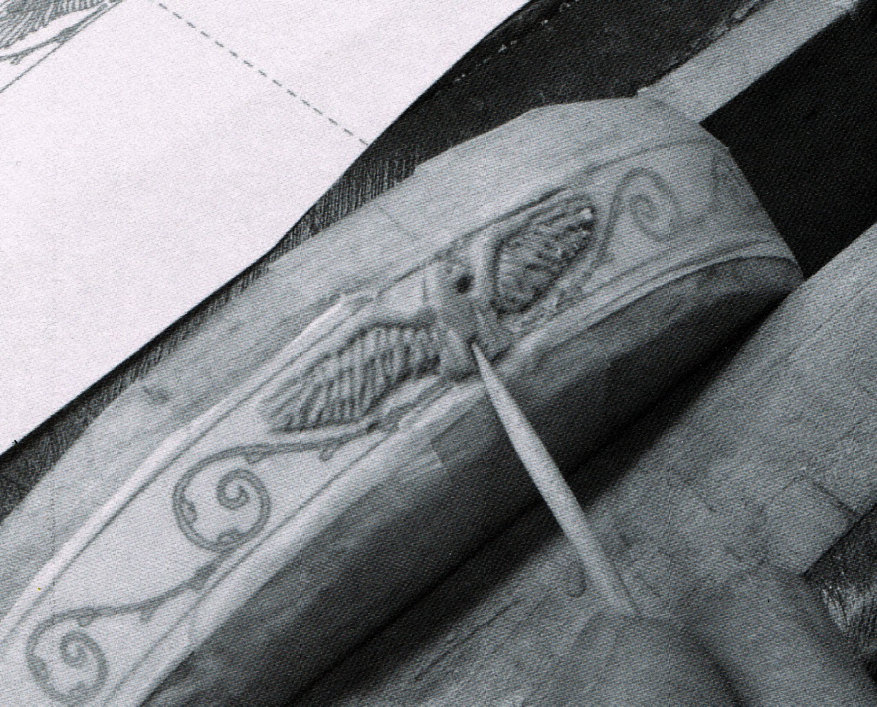
Ever since I saw samueljr's model on this forum, I've been intrigued with the possibility of incorporating a pulley into the cap rail at the bow. Samuel's model has the bowsprit to the port side, and the pulley on the starboard side, which is also correct. Apparently, it was done both ways. It wasn't until I saw photos of two contemporary models that had the pulley on the port side that I decided to go for it. One model was rigged, and the other was not. As much as I would like to show you those photos, I thought better of it, considering the current ongoing discussion on copyrights. Once I got passed the decision to do surgery on the painted model, the modification was not that difficult. The cap rail overhang was trimmed down, and the new piece was fabricated. Contemporary models seem to indicate that these pieces were actually separate from the cap rail, so the modification did not impact the accuracy of the model. On some contemporary models, this piece feathers nicely into the cap rail edge, and on others there is a distinct slight bump at the aft end. I opted for the latter version. A closer study of the reference photos showed that the starboard side also had the same shaped piece, but no allowances were made for a pulley, since the bowsprit would have been mounted on that side. I'm currently working on that piece. BobF

- 277 replies
-
- 13
-
-
- model shipways
- 18th century longboat
- (and 1 more)
-
Hey Geoff, It was great hanging out with you last night at Kurt's. Your Connie is awesome! I think using a flash drive to showcase your model at meetings would be a great idea. I know the membership would enjoy seeing the photos, especially those that don't have Internet access. Take care, and happy holidays. BobF
-
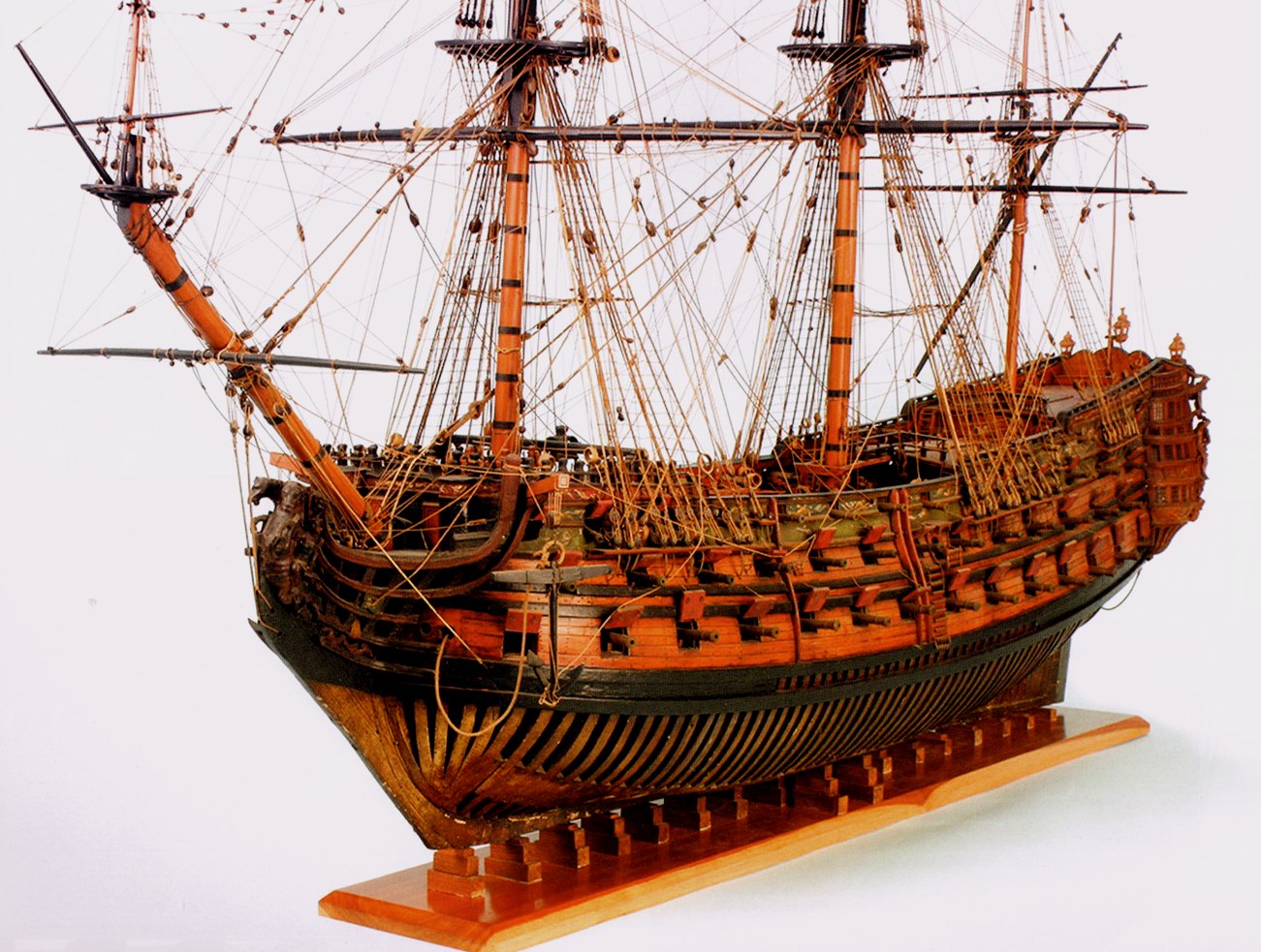
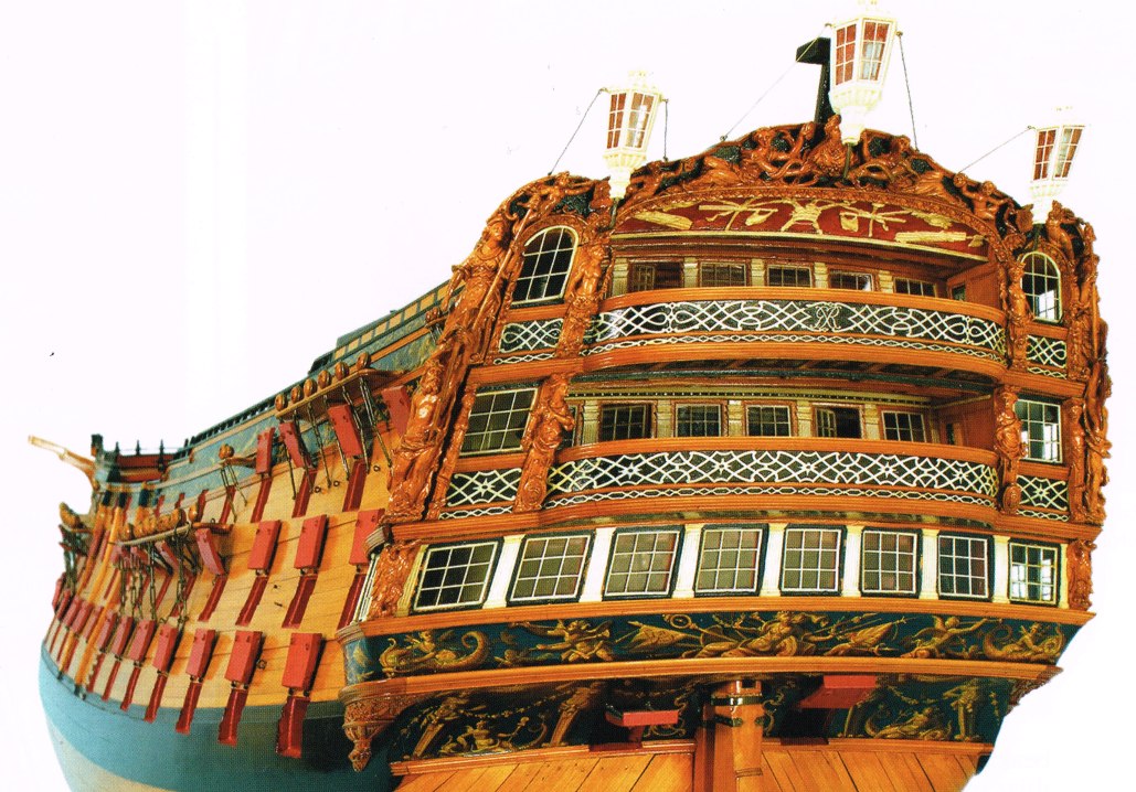
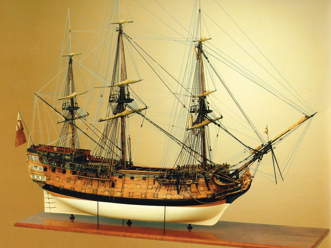
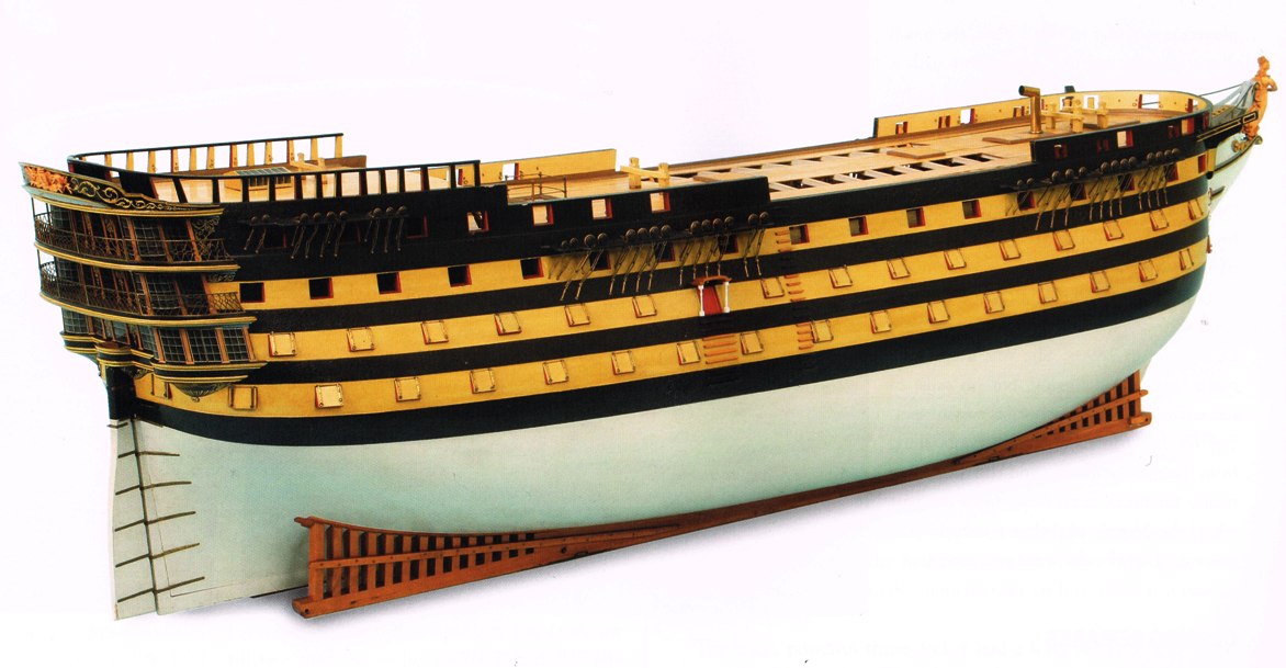
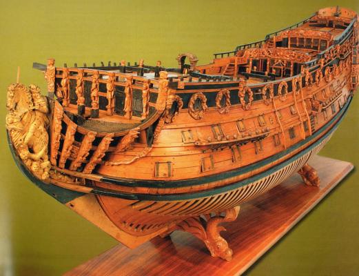
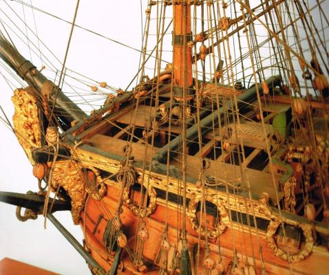
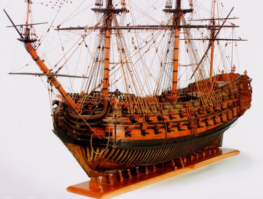
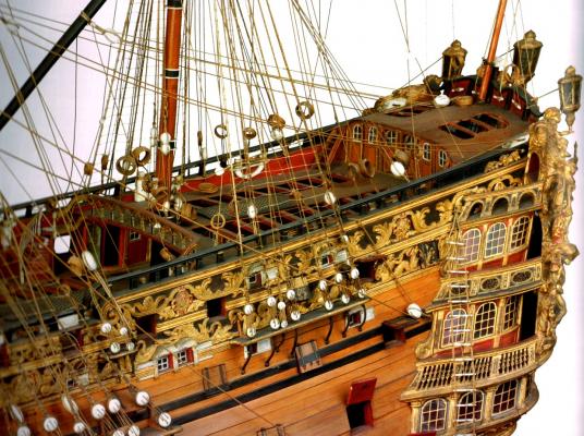
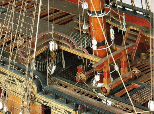
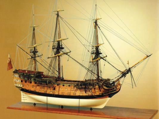
Hello all, Many good things have already been stated concerning this excellent book. I hope you don't mind if I add a few more. BobF The Rogers Collection of Dockyard Models At the U.S. Naval Academy Museum First & Second Rates Volume I by Grant H. Walker Distributed by: Sea Watch Books, LLC, Florence, Oregon www.seawatchbooks.com, seawatchbooks@gmail.com In his opening remarks, the author, Grant Walker, states that it took eleven years to assemble the information that is the basis for The Rogers Collection of Dockyard Models, Volume I, and the several future volumes that are planned. There is no doubt that from the naval historian’s and ship modeler’s perspective, it was well worth the wait! In this initial volume, Walker describes, in detail, the results of his research on the seven Royal Navy three-decker 1st and 2nd rate ships contained in the collection. These models represent vessels that served from the mid 17th century into the 19th century, and, needless to say, they are magnificent! This is the first comprehensive study of Roger’s models since 1946, when the Naval Academy published a pamphlet outlining the entire collection. Revised editions were printed on four occasions, but only the photographic content was changed. In every case, the illustrations were in black and white. In what will be the standard approach for all the volumes in this series, each featured model is described in detail, along with its provenance, and a brief history of the actual ship or class that the model represents. Every segment begins with a table that offers comparisons between the dock yard model and the vessel the model represents. In some cases, the Establishment applicable to the model’s period of representation, is incorporated into the tables. The first model discussed is the impressive First Rate, Britannia, 100 guns (1682/1700). Walker immediately adds intrigue by stating that there is considerable reason to doubt whether this model is actually Britannia. He offers compelling reasons why this may be the case, in spite of the many visual elements that compare favorably with contemporary images, and the ship’s name appearing above the topgallant roundhouse entrance. As is the case with the other models in this book, a detailed construction analysis is provided. It includes CT scans, X-rays and numerous below-deck photos taken with an arthroscope. The next model presented by Grant Walker is the Second Rate St. George, 90 guns (1701). Although comparable to Britannia in terms of guilt ornamentation, it is the model’s remarkable suite of original masts, yards and rigging that set this Second Rate apart from other contemporary dockyard pieces, including those featured in this book. Nevertheless, Walker opts to concentrate on the actual ship’s history, as well as the model’s provenance, and construction details, which feature numerous below deck photos. Several excellent illustrations of the St. George’s rigging, accompanied by brief descriptions, are provided, but Walker prefers to defer to the two classic works by Dr. R. C. Anderson, for those interested in learning more about warship rigging during this period. The next chapter features an unidentified British Second Rate Ship, c.(1715-1725). Based on the model’s provenance, this may be the most controversial model in the Annapolis Collection. Extensively restored in 1923 to include the upper decks, quarter galleries, masts, yards, rigging and decoration, this dock yard model is a far cry from its original appearance when purchased by Colonel Rogers. Walker’s explanation for the controversy, as well as his efforts to identify, and rationalize the appearance of the model, makes for some great reading! Although referred to as Model No. 39 in the Rogers Collection, the British First Rate Royal William, 100 (1719) was actually the first dockyard model purchased by Colonel Rogers. The provenance of this magnificent ship model is unknown prior to the Twentieth Century. Yet, the author provides an intriguing, and somewhat bizarre, tale of how Royal William was eventually obtained by Rogers. The subsequent detailed analysis of this model, accompanied by a wealth of outstanding photographs is worth the cost of this book by itself! The author states that Model No. 70, the British Second Rate Princess Royal, 90 (1773) is considered one of the finest examples of the ship modeler’s art in the collection. Yet, as little as twenty years ago, this remarkable piece was literally falling apart. An extensive rebuild by Rob Napier, which is the subject of another SeaWatch book, brought this beautiful model back from the brink of disaster. The story of this model’s provenance is most noteworthy, while the photos of the frieze work and carvings are exceptional, to say the least. Apparently, contradictions among models as old as those in the Rogers Collection are quite common, and the British Second Rate Duke, 90/98 (1777) is no exception. Grant Walker provides some intriguing theories concerning the construction of this impressive model. Arguments are also provided that in spite of some notable facts to the contrary, this Second Rate does indeed represent the Duke. Also, a rarity among British models in the collection, is the full set of furled sails this model features. The British First Rate Royal Adelaide, 110 (1828) is the most recently built model showcased in Volume 1, and it is probably the most radical. The unique bow and stern are discussed in detail, with a contemporary diagram of the stern gun arrangement being provided by the author. Walker’s analysis of the slipway and ingenious case will leave the reader amazed. He also explains why, in spite of the First Rate’s rock-solid provenance, this model still presents a few mysteries. The book concludes with six appendices. They are Dockyard Models Defined, Colonel Roger’s Biography, Charles Sergison (a previous owner of Rogers Collection models), Scales & Measurements, Caretakers of the Collection, and a brief explanation of the collection’s Catalog Numbers system. The Rogers Collection of Dockyard Models, Volume I, features an oversized 11 3/4x10 format with hundreds of high definition photos, printed on quality paper. This book is a remarkable achievement, and would be an excellent addition to the library of any maritime historian or model ship builder.


- 3 replies
-
- 12
-
-
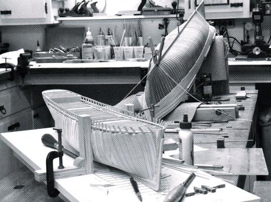
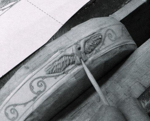
Hello all, Here is a review that appeared in my club's newsletter. I thought I'd share it with you. This is a remarkable book! BobF Young America 1853 Volume I: Hull Construction Text, Photos, Plans & CD by Edward J. Tosti Distributed by: Sea Watch Books, LLC, Florence, Oregon www.seawatchbooks.com, seawatchbooks@gmail.com In his opening remarks, Edward Tosti, states that the drafting and construction of a fully framed extreme clipper ship can be a daunting endeavor. Unlike the meticulous documentation available for Royal Navy vessels, the short-lived period of the extreme clipper ship provides very limited technical information. This is reflected in the scarcity of model making books dealing with this period, and the nonexistence of publications describing framed structural models. Tosti sites the works of William L. Crothers, and a number of other references listed in the bibliography, as the primary sources for Young America 1853. Although the primary focus of this book is the construction of a 1:72 scale, fully framed up model, the author has made an effort to appeal to a broader range of modelers. The latter portion of Volume 1 deals with building a 1:96 scale, plank on bulkhead model of the Young America. Even at this smaller scale, the hull measures a very impressive 40” in length. In order to accommodate this sizable amount of information, and to avoid repetition, Tosti, on occasion, makes reference to his earlier work, the Naiad Frigate. Although not absolutely necessary, he suggests that having these additional books may compliment the process descriptions needed to construct either scale model of the Young America. The book starts out with a brief history of how the extreme clippers evolved, the innovative methods used to construct them, and the men who actually designed and built them. Finally, a short description of the Young America’s career is provided. The second chapter, “Planning for Construction,” is unique in many ways, and exemplifies the author’s attention to detail in guiding the model builder. Mr. Tosti discusses the many facets of planning your project. Some of these include scope (what to build), the level of quality desired, detection and correction of errors, machine, hand and specialty tools, what species of woods to use, and of course safety. Actual construction begins with the keel structure. The author goes into great detail, and includes obscure fittings such as keelson joint wedges and water stops. The use of dark glue is also described for enhancing the visibility of glue joints. Scrapers play a prominent part in creating rabbets, and patterns are provided for fabricating the correct shapes. The author goes on to describe his design for a model shipway or building board. Although, later in the book, additional information is provided for a smaller, simpler, less costly design for the POB model, the more complex device can actually be used for both versions. You might say that the three chapters dealing with the framing of the model are the heart of this book. They begin with the square frames. Although less complex than the examples found on 17th and 18th century Royal Navy vessels, the shear number that need to be constructed on this large model present a challenge. The author outlines an innovative process he calls “Pin-indexed Frame Assembly.” Tosti states that this procedure is simpler, faster, more accurate, eliminates the need for elaborate clamping fixtures, and allows the modeler to bevel the frames before erecting. It is at this point that the author reminds the reader about the need for accuracy. The smallest error in each frame can result in a cumulative variance that will cause major problems. A detailed description for mounting all the frames ensues. This includes the square frames, keelson, fore and aft deadwoods, and half and full cant frames,. Patterns for all these challenging components are supplied in the CD that comes with the book. The innovative materials used for simulating iron and copper bolts are also discussed. One of the most intriguing aspects of the chapter that deals with the hold ceiling and deck clamps, involves the installation of a lattice of simulated iron bands that were used during the nineteenth century to prevent hogging in wooden hulls. Tosti outlines his method for cutting, blackening, and installing the 1/16” wide copper strips on the inner hull surface. Since the bands will be barely visible when the model is completed, the author admits to simplifying the installation. However, he does describe how his method deviates from actual practice. With the hull framing completed, decks preparation is next. This topic includes beams, hooks, knees, carlings, and pillars. In every case, multiple pieces are required, and the author offers some helpful hints, which will expedite their construction. Mindful that not everyone’s workshop has the same equipment, Tosti offers six different options for creating the round-up on the deck beams. One daunting revelation involves the fact that Young America possessed approximately 1000 knees. Diagrams are provided in the CD for the various types, and the author offers a solution for mass-producing them. With the array of different parts that have to be installed, a 23-step outline is provided that culminates with the installation of the hatchways, central deck facilities, and decking. Tosti states that for this phase of the model, adhering to this guide is not absolutely necessary. However, for the next sequence that deals with the topside planking and rails, following the steps, as listed, is highly recommended. This is primarily due to the fact that Ed advocates pre-painting parts before mounting them permanently. A small bit of advice, but no less valuable than his extensive explanation for creating the model’s decorative carvings, which is worth the cost of the book by itself. The next segment is devoted to lower hull detailing, and is loaded with numerous hints and tips. Procedures are outlined for fabricating waterways, binding strakes, limber channels, scuppers, hawse holes, metal sheathing, gudgeons and pintles. Tosti’s method for mass-producing these last two items is especially innovative. The final chapter in Volume I that deals with information applicable to both versions of the Young America discusses work on the upper decks, and includes the poop, main deck, and forecastle. Details for the pin rails, mast partners, hatch and cabin coamings, pump suction pipes, decking, chain pipes, mooring bits, boomkins and catheads are just a few of the items outlined. How the aft cabins looked is not known, and Ed does an admirable job designing a typical interior for his model. Drawings for this layout are included in the CD. The last two chapters are devoted entirely to building the 1:96 scale POB model. Although this version was referred to often in previous chapters, this segment begins with basics, the constructing of the model shipway and accessories. Going forward from there, the author’s concise style of writing, and excellent photos, provide the reader with a clear understanding of how to build this type of hull. There’s no doubt that Tosti’s methods could apply to any scratch-built POB model. In addition to the CD, this book comes with a packet of eight drawings. Six are devoted to the 1:72 scale model, and two feature the smaller 1:96 version. This review has barely scratched the surface as to what this book has to offer, but there’s no doubt that Young America 1853 will become a classic reference for modelers and clipper ship history buffs. SeaWatch states that Volume II is a year away, which, for many of us, can’t come soon enough!

- 56 replies
-
- 11
-
-
Dr. Per: Due to the number of finished examples in this group, there's no need for you to rely entirely on your "mind's eye." Check them out, and pick the design that appeals to you the most. That's what I did. BobF
- 335 replies
-
- 4
-
-
- 18th century longboat
- Finished
- (and 1 more)
-
Toni - I blackened the parts, and I couldn't detect any difference between the two solders. The parts were pickled in Sparex prior to being blackened. The blackening agent was Birchwood Casey. BobF
- 277 replies
-
- 3
-
-
- model shipways
- 18th century longboat
- (and 1 more)
-
Kurt - I've blackened the bowsprit fittings already, but not the mast brackets. I'll leave them bright until after the meeting. BobF
- 277 replies
-
- 1
-
-
- model shipways
- 18th century longboat
- (and 1 more)
-
Hi Toni, I haven't blackened the parts yet. However, I tend to think that, due to the fact that the layer of Stay-Brite is so thin, it won't be visible once the bracket is mounted on the mast.. It's confined to the inner face of the ring. I'll blacken the part soon, and post the results. BobF
- 277 replies
-
- 2
-
-
- model shipways
- 18th century longboat
- (and 1 more)
-
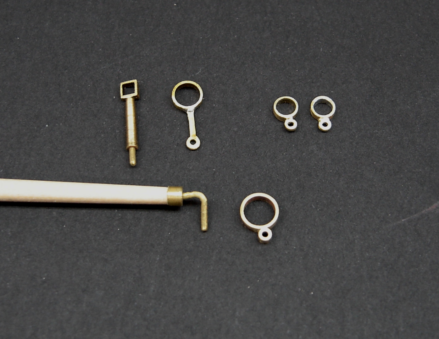
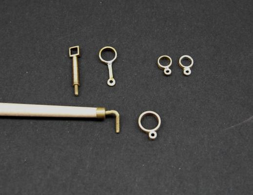
Here is a photo of the "iron work" for the boom, bowsprit, and mast. Rather than using brass flat stock to form the various pieces, I thought I'd try something a little different. Every fitting was made with slices of brass tubing. In each case the components were silver soldered together. I've never done any silver soldering, so this was a new experience for me, and I have to admit that I enjoyed it. It's quite possible that Stay-Brite would have worked just as well, but I wanted to try something new. I really lucked out on this procedure. In every case except one, the inside diameters of the tubing were spot on for the boom, bowsprit and mast locations. The one exception was the top bracket on the mast, which had a little play at the location where it should be mounted. I solved that problem by applying some Stay-Brite solder to the inner surface of the ring, and reaming it out. It really didn't take much to snug up the bracket. BobF
- 277 replies
-
- 18
-
-
- model shipways
- 18th century longboat
- (and 1 more)
-
Hi Jonny, Welcome aboard, and don't concern yourself about being slow. When it comes to being slow, you'll find my picture next to the definition in the dictionary! Anyway, this longboat kit is an interesting subject since it makes a great model right out of the box, or you can make subtle changes to it that really don't add much work to its construction. Good luck, and I look forward to following your build log. BobF
-
I rarely use my Dremel drill press for actually drilling holes. Never the less, with that pivoting head, it's a versatile and valuable tool. BobF
- 277 replies
-
- 2
-
-
- model shipways
- 18th century longboat
- (and 1 more)
-
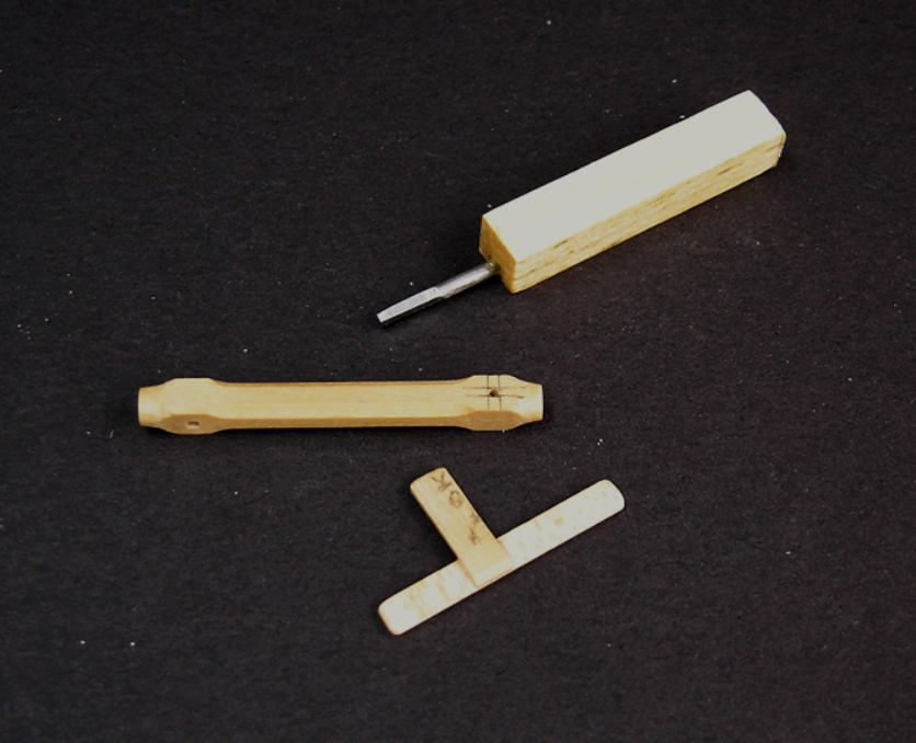
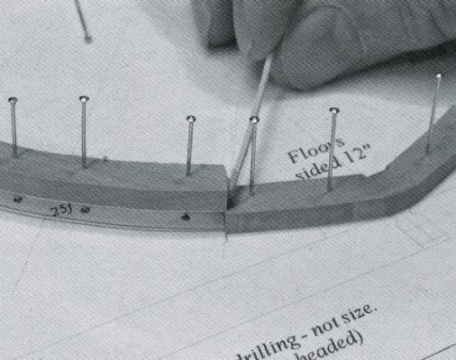
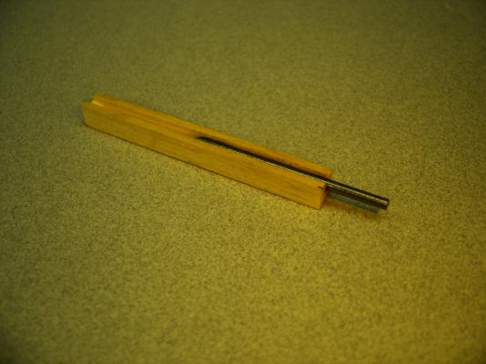
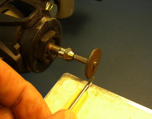
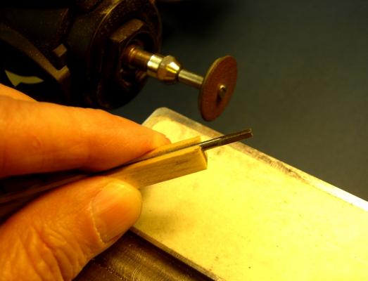
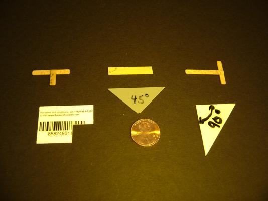
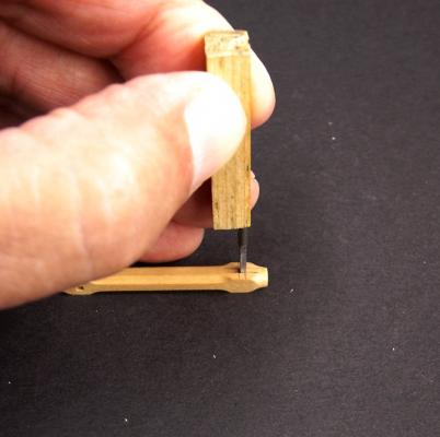
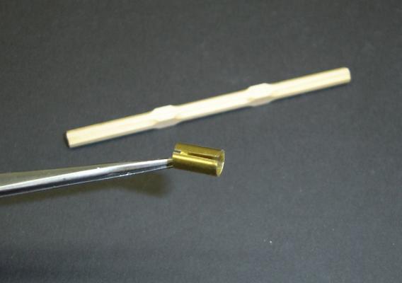
JS - I guess you can call it a "specialty tool," although it's really nothing more than a hand-made broach. I start out by cutting a piece of scrap wood, so the four sides are as square as possible to each other. The stock can be either square or rectangular in cross-section, it doesn't matter. I then cut a slot in one side wide enough so it will take a small finishing nail with the head cut off. The nail is epoxied in the slot. Make sure the nail is completely below the surface of the wood. I then set up my Dremel drill press with the head rotated 90 degrees. For this procedure, one of those small abrasive disks works well. Make sure you wear some eye protection when you do this! These disks have a nasty habit of shattering. I then start carefully grinding down the sides of the nail, rotating it periodically, so a square shape is formed. As I get close to the desired size, I start measuring the head with a pair of digital calipers. I believe the one in these photos was about .045" square. In order to make the mortise, I start out by drilling a hole that is equal to, or slightly smaller in diameter than the dimension of the broach. The hardest part of this procedure for me was getting the broach lined up properly over the hole. For that reason, I would highly recommend that you make yourself a miniature T-square. I have a small collection of various triangles and squares that are some of my most usefull tools. Take the square, and mark off the limits of the hole on two sides. The other two lines can be drawn by dragging a compass along the edge of the plug, with the lead lined up with the edge of the hole. Carefully line up your broach with the lines, and gentley tap the broach a few times. This should give you a slight impression in the wood. If the impression looks good, put the broach in the depressed area, and tap a little more forcefully. Check it periodically as you do this. I messed up a couple of windlasses trying to do this, so I would recommend you practice with some scrap before you commit to the actual piece. I apologize for being so "long winded." I hope you find this useful. BobF

- 277 replies
-
- 14
-
-
- model shipways
- 18th century longboat
- (and 1 more)
-
Hi David, The photos Chuck provided for this group have been my primary source. One of the SeaWatch books on the Kriegstein collection also has some very nice photos of a contemporary model. "The Arming and Fitting of English Ships of War 1600-1815" by Brian Lavery has also been helpful. BobF
- 277 replies
-
- 3
-
-
- model shipways
- 18th century longboat
- (and 1 more)
-
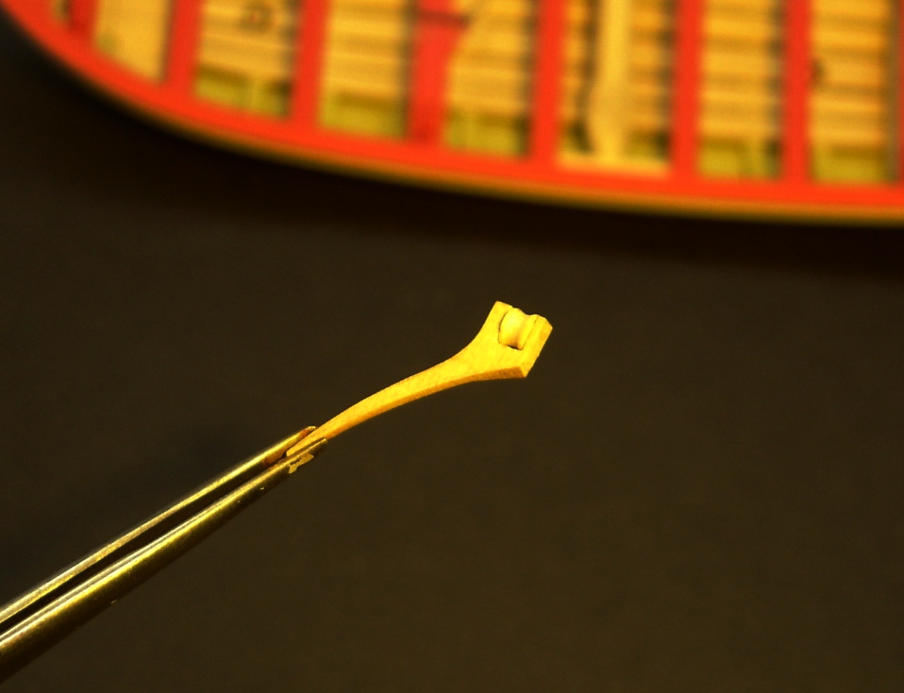
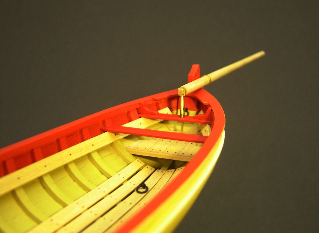
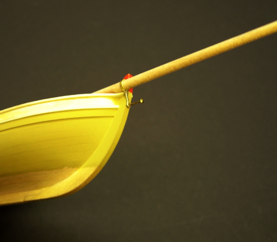
I've started working on the mast, boom, gaff and bowsprit. Here are some photos of the bowsprit temporarily mounted in position. The first two photos show the barcket that is mounted at the heel of the bowsprit. NMM models show a square tenon inserted into this bracket, so I soldered a piece of square brass tubing to some brass rod. The tenon is actually a 1/16" square piece of boxwood inserted into the end of the bowsprit. Per NMM models, I also inserted this bracket into the first thwart, rather than into the floorboards. The brass rod protruding below the thwart, still needs to be trimmed. The next two photos show the other bowsprit bracket, which was made with some soldered brass tubing and trimmed flat stock. I didn't want to press the brass pin all the way in, since I wasn't ready to mount it permanently. BobF


- 277 replies
-
- 13
-
-
- model shipways
- 18th century longboat
- (and 1 more)
-
Erik - Awesome work! Congratulations on an outstanding planking job. Can't wait to see how the rest of the model turns out! BobF
- 222 replies
-
- 1
-
-
- 18th century longboat
- model shipways
- (and 2 more)
-
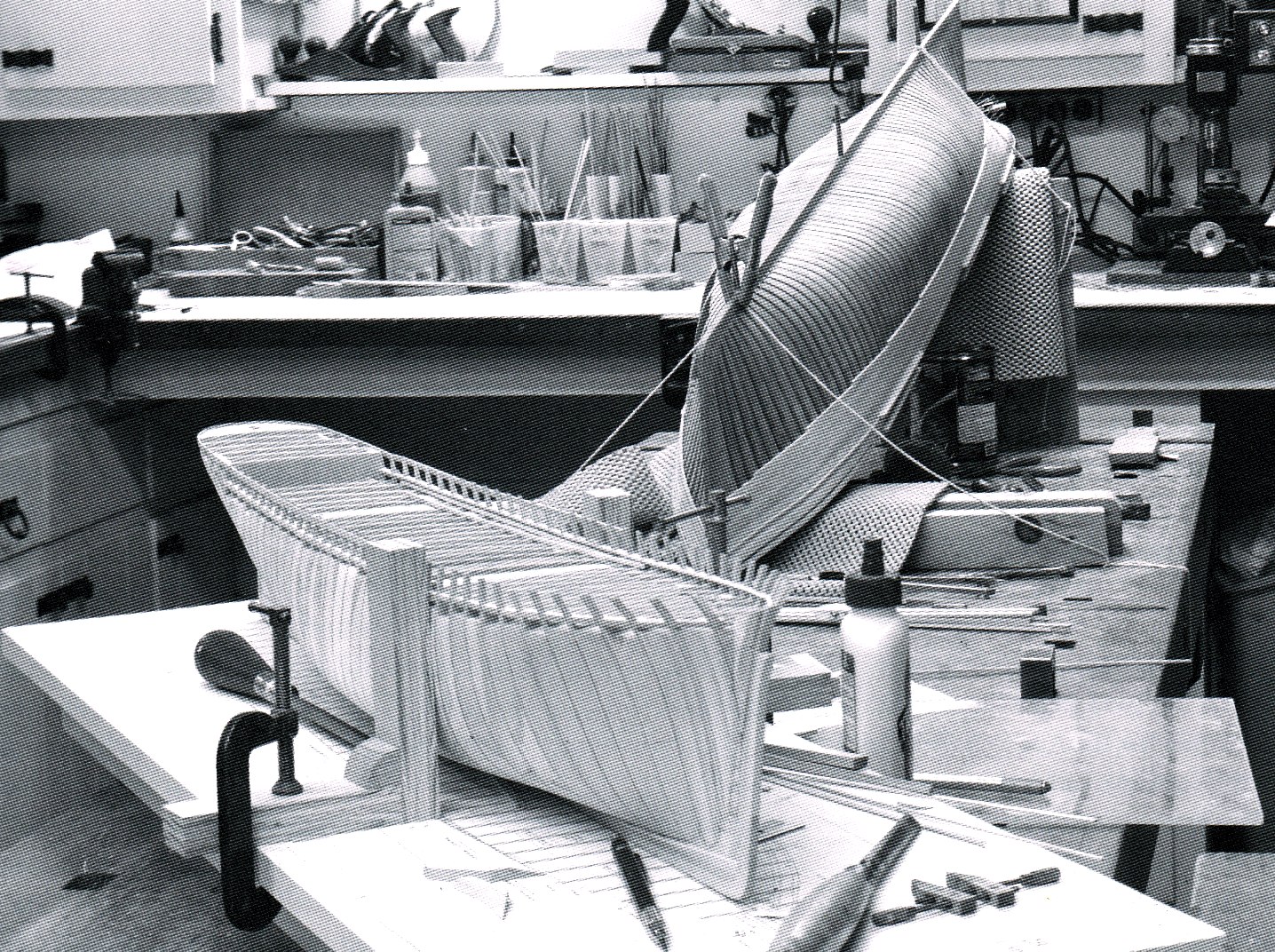
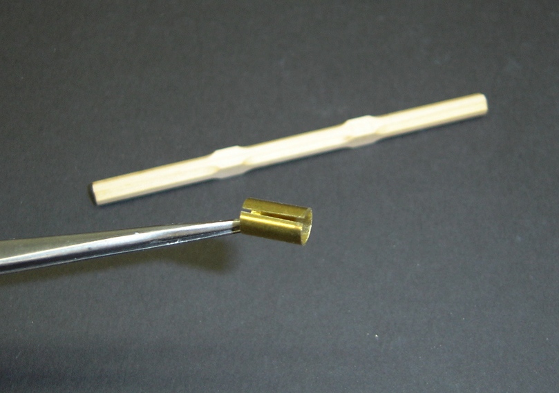
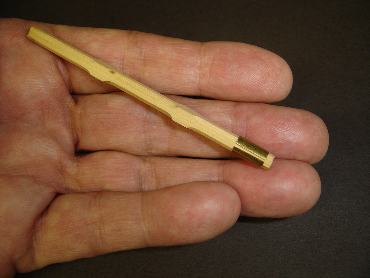
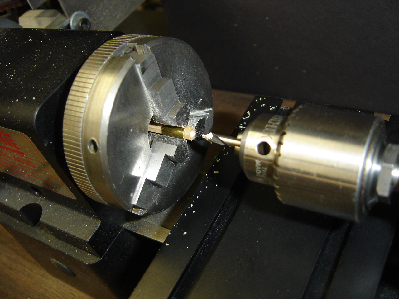
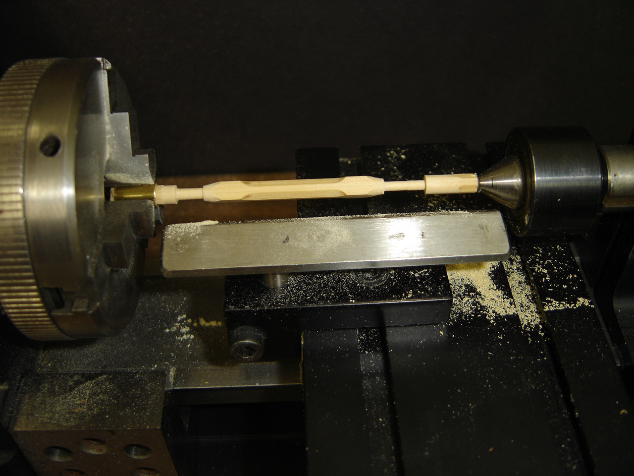
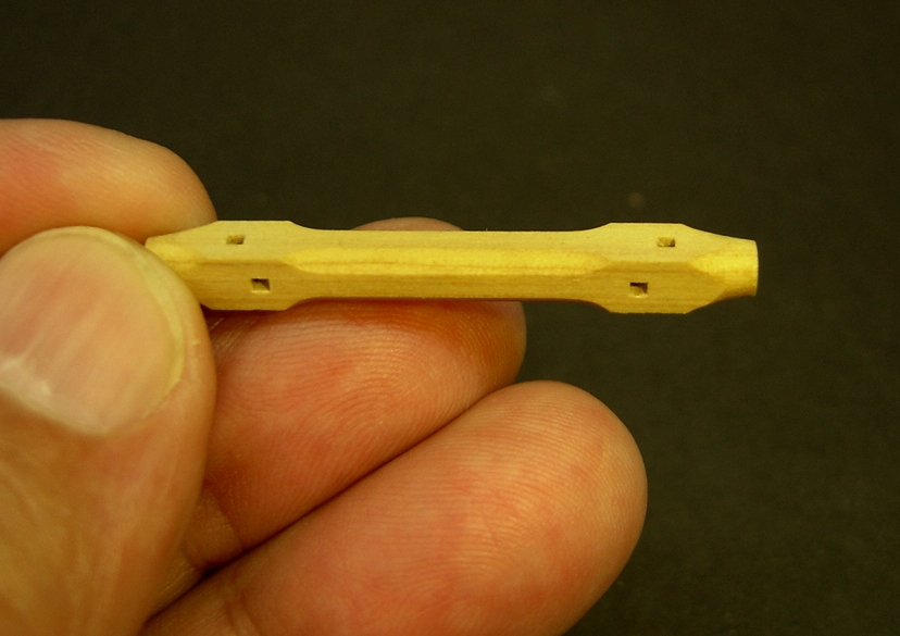
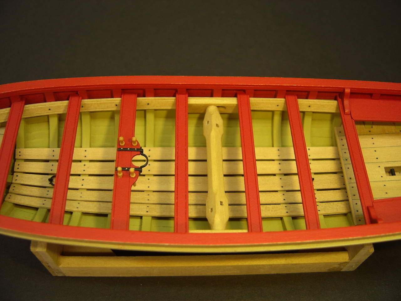
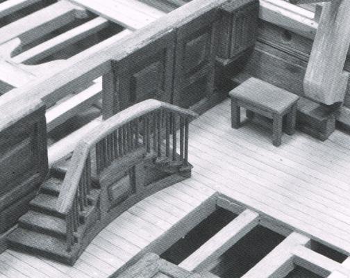
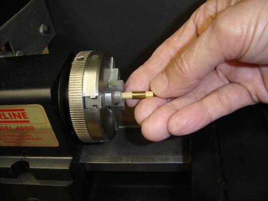
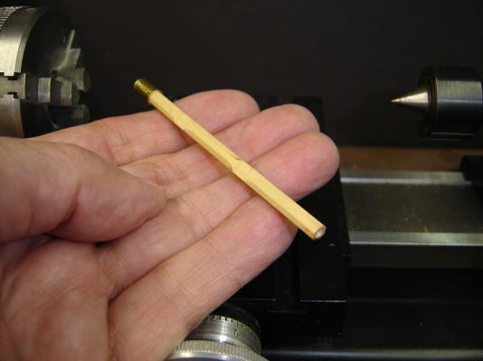
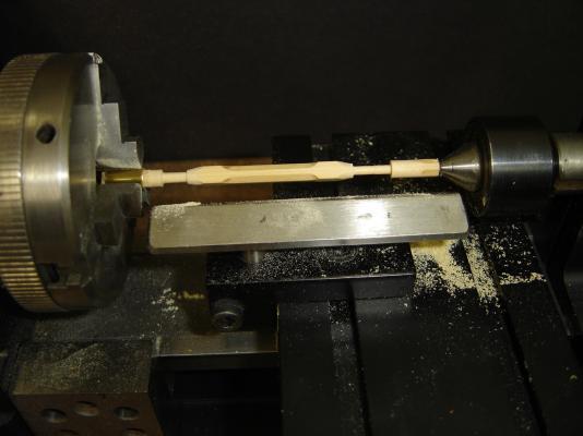
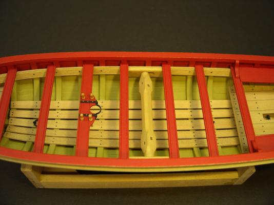
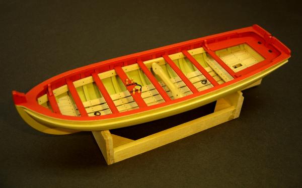
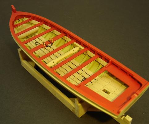
If you look at contemporary long boat models, all the windlasses seem to have a curious conical taper at each end. I found this too intriguing to pass up, and decided to try duplicating the shape on my lathe. An easy way to chuck up an eight-sided piece in a three jaw chuck is to use a brass sleeve that has a slit cut in it. This allows the sleeve to compress as the chuck is tightened. The only drawback to this is whether or not you have brass tubing suitable for the piece you are working on. The fact that I planned to use this sleeve is also the reason I made the windlass plug as long as it is. First of all, I needed to center drill the windlass at one end so it could take the tailstock. The sleeve was then moved to the other end of the piece, and mounted in the lathe. The only problem I encountered with this procedure, is that I had to be careful not to damage the sharp edges of the four flat surfaces at each end while creating the tapers. If you go back to the first photo in this particular post, the mortises in the contemporary windlass are offset on adjacent surfaces. For what it's worth, I found that duplicating that on my windlass made any misalignment problems less obvious. Here are some photos of the windlass and thwarts in position. However, they still aren't glued in place. I'd like to get some other procedures done on the model before I commit to that. BobF


- 277 replies
-
- 24
-
-
- model shipways
- 18th century longboat
- (and 1 more)
-
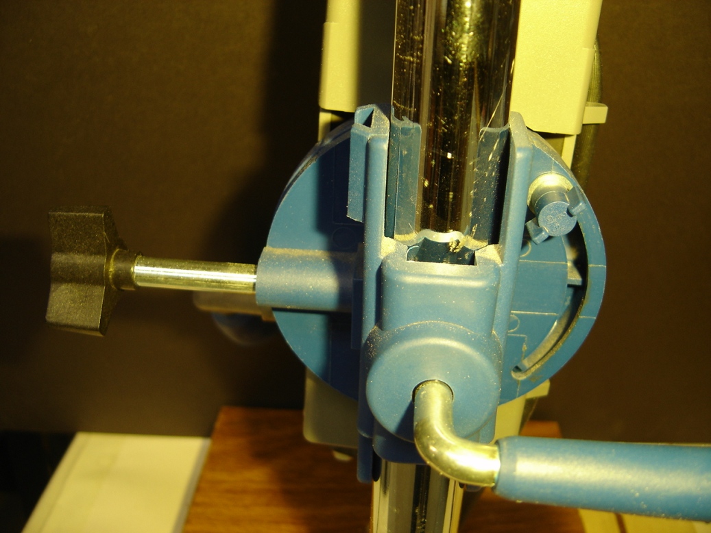
I suspect that Dremel, over a period of time, has continued to tweak there drill press. It's possible that I may have a different model than Jack. Here is a photo of the backside of my unit, which is a Model 220. On my unit, that little blue wing nut on the right side also has to be loosened, so the head can be rotated. As you can see, it sits inside a circular track. BobF

- 277 replies
-
- 1
-
-
- model shipways
- 18th century longboat
- (and 1 more)