shipmodel
-
Posts
941 -
Joined
-
Last visited
Content Type
Profiles
Forums
Gallery
Events
Everything posted by shipmodel
-
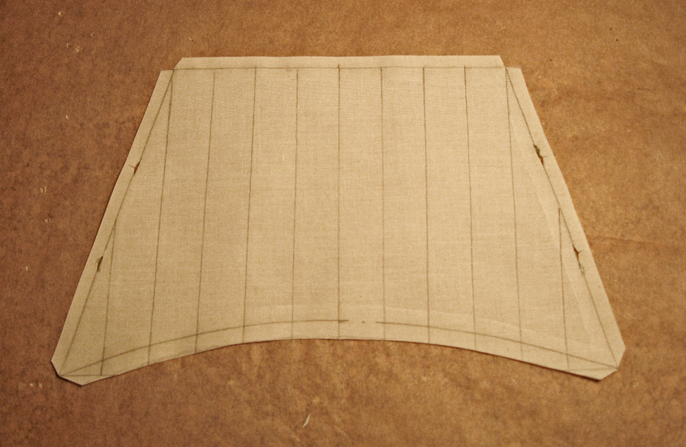
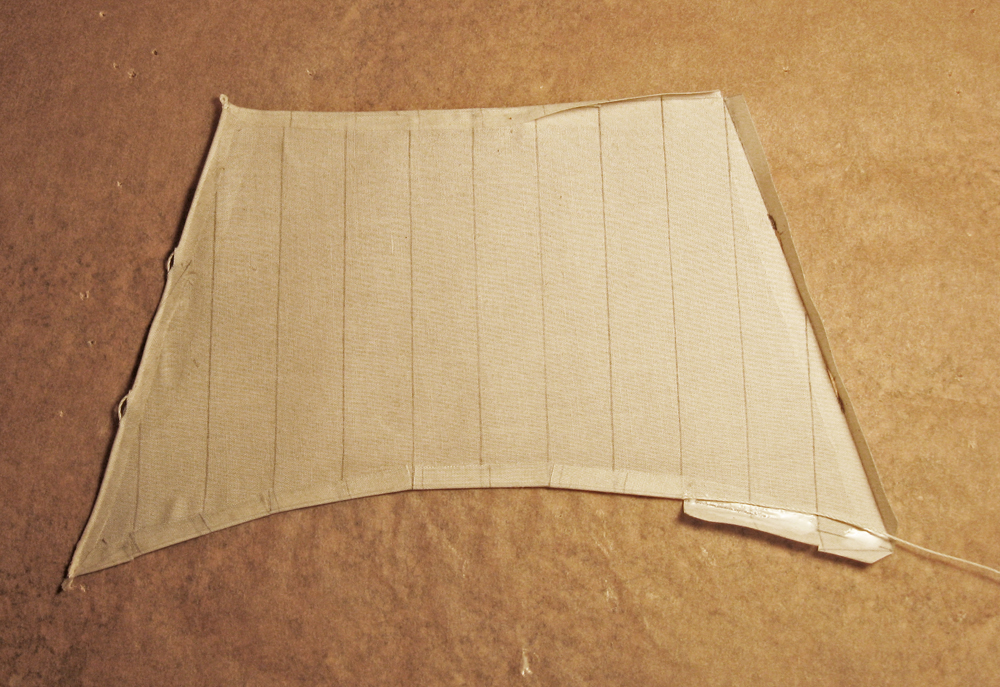
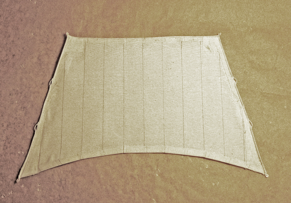
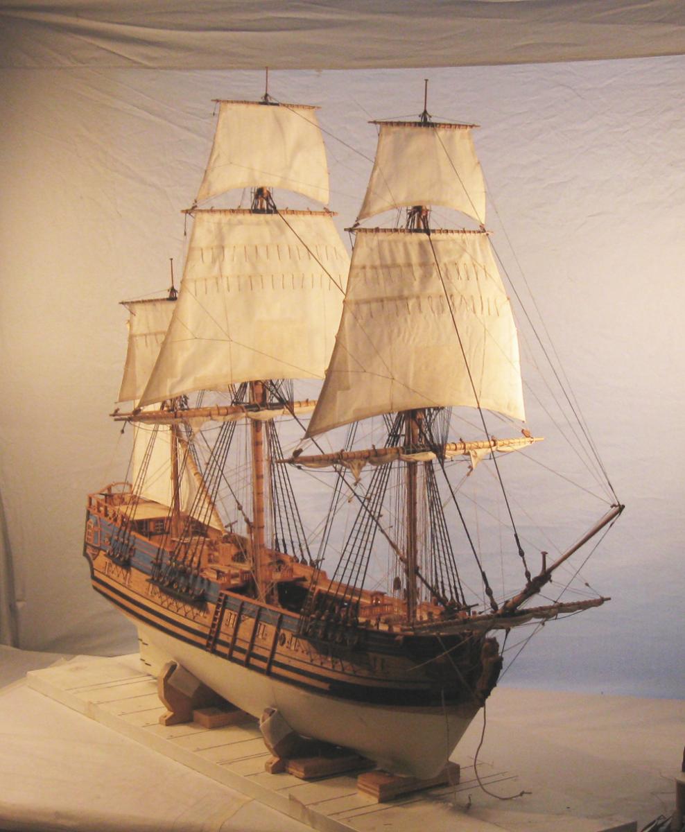
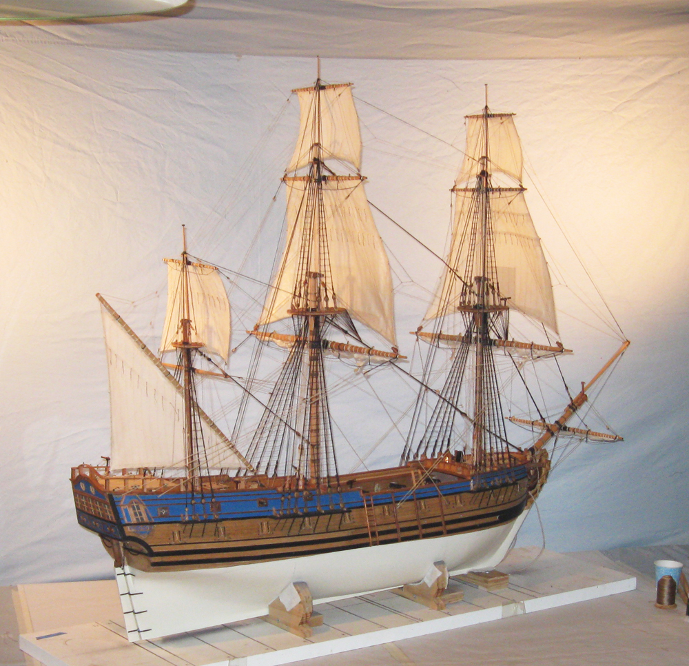
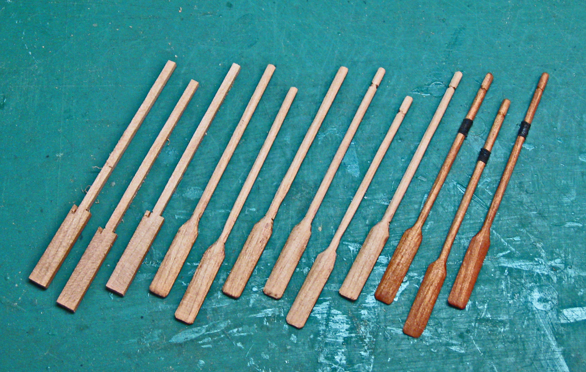
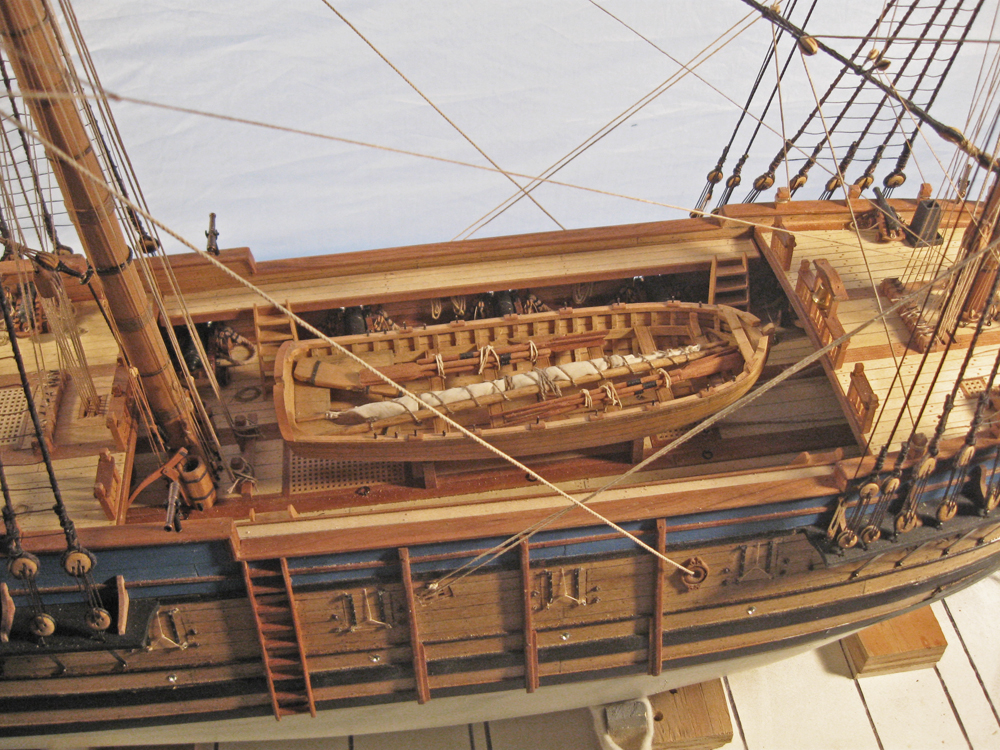
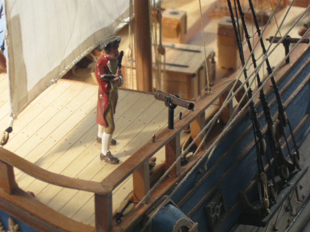
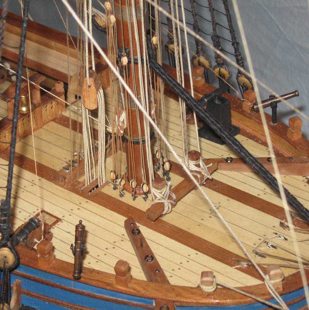
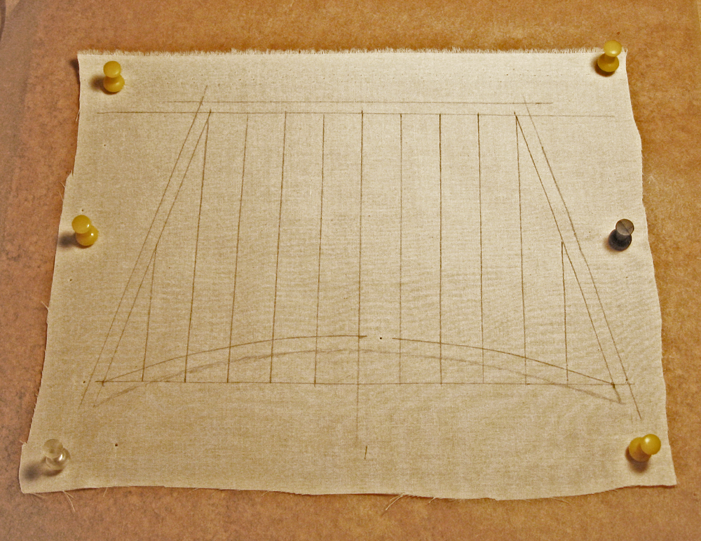
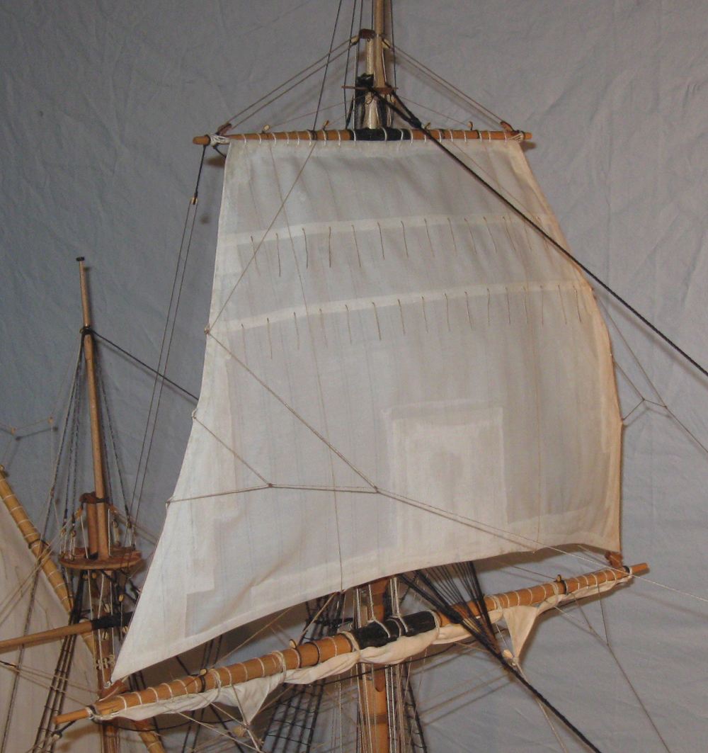
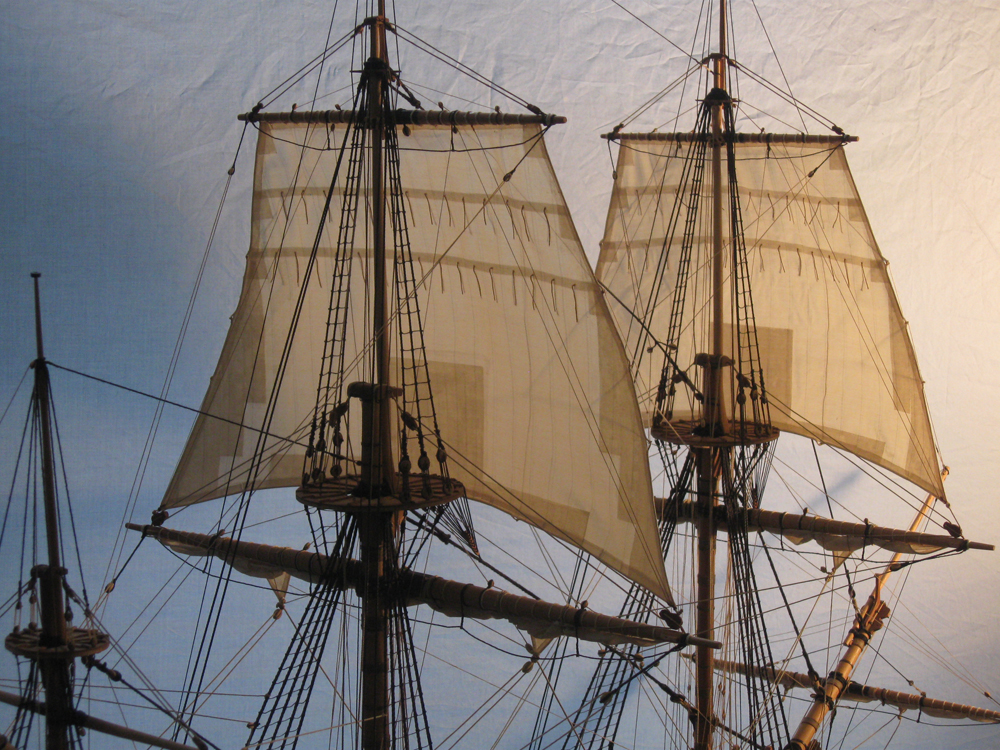
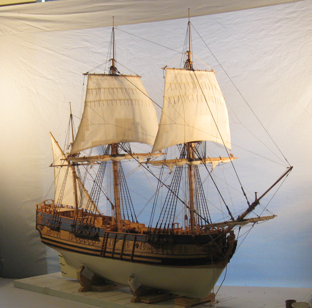
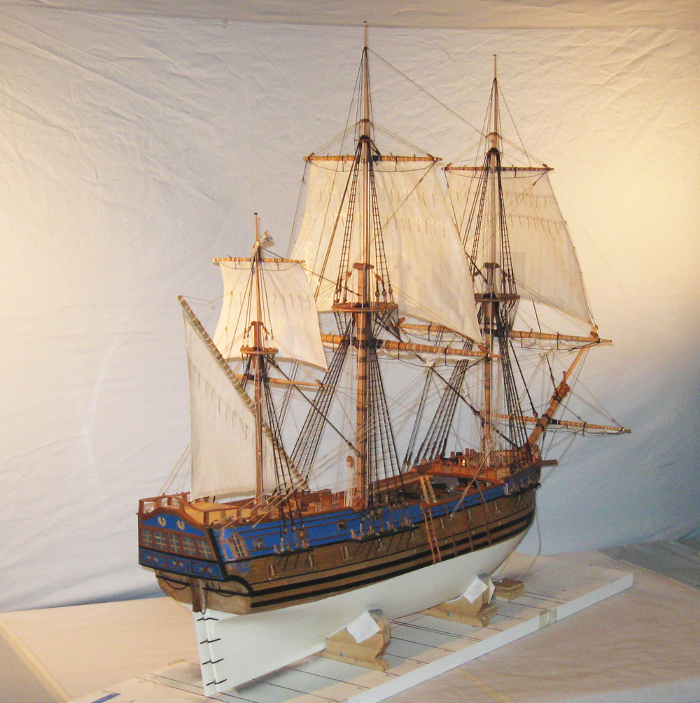
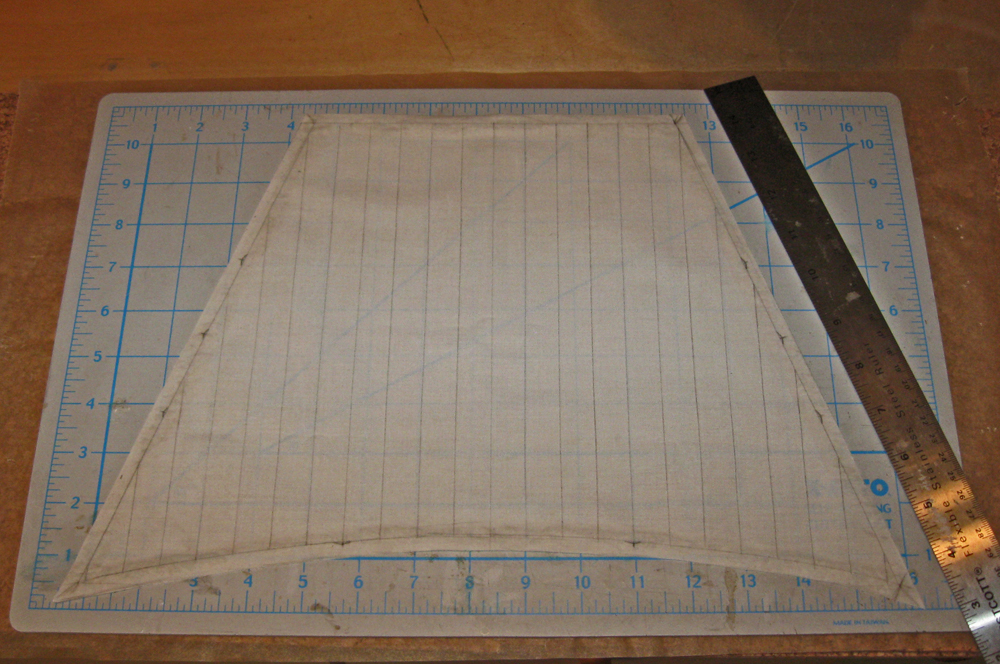
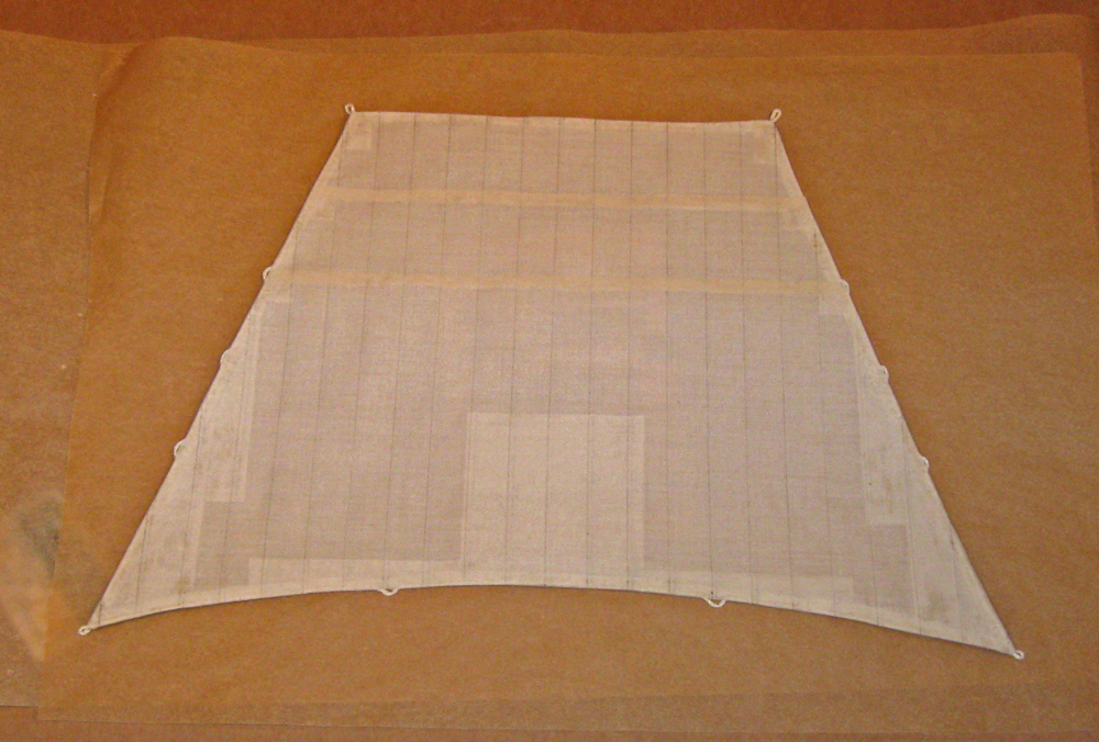
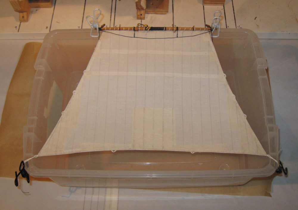
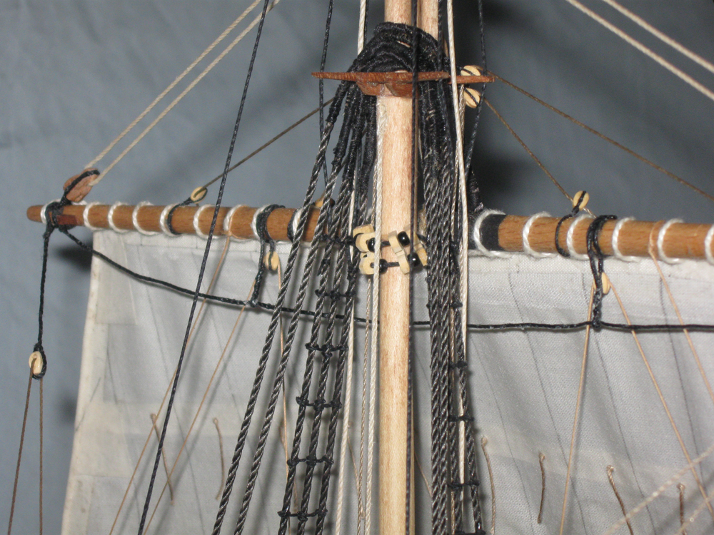
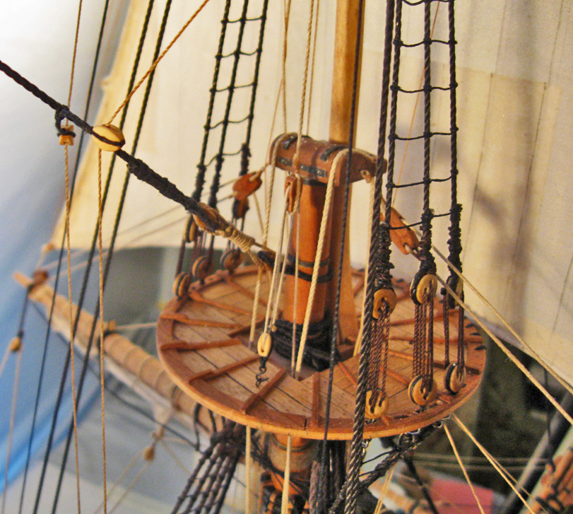
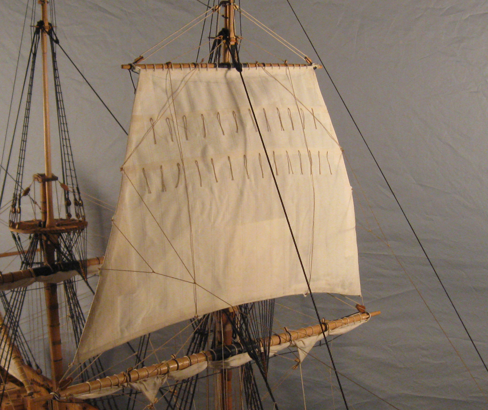
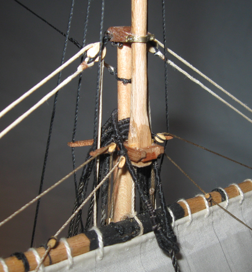
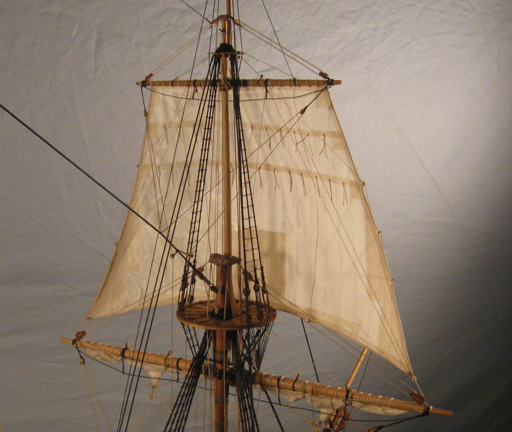
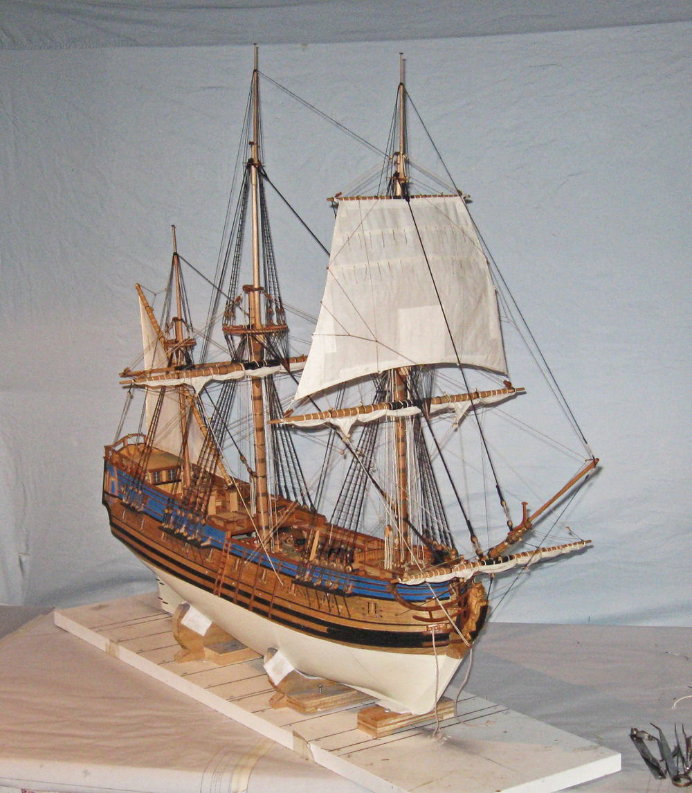
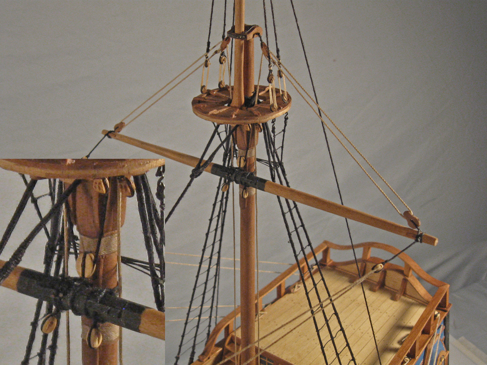
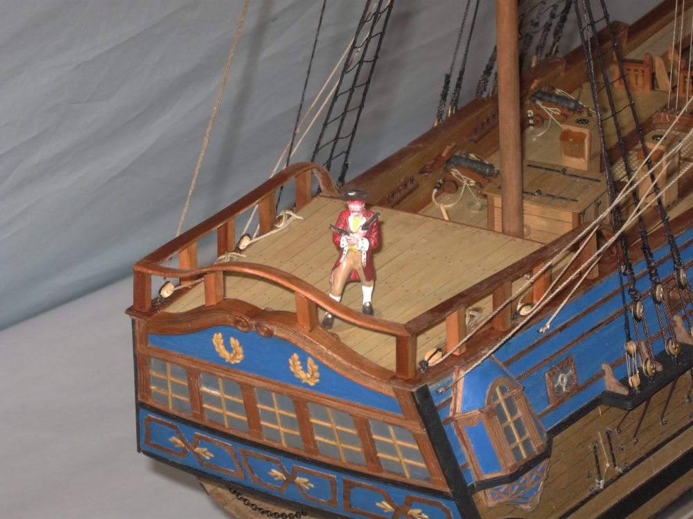
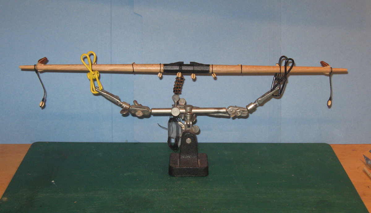
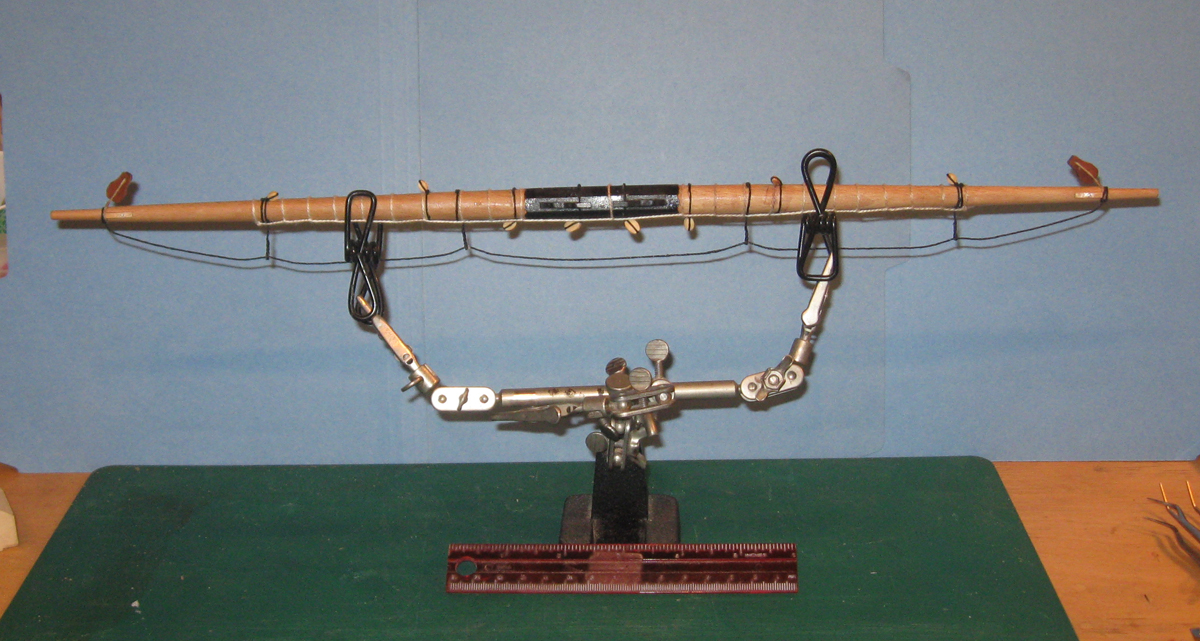
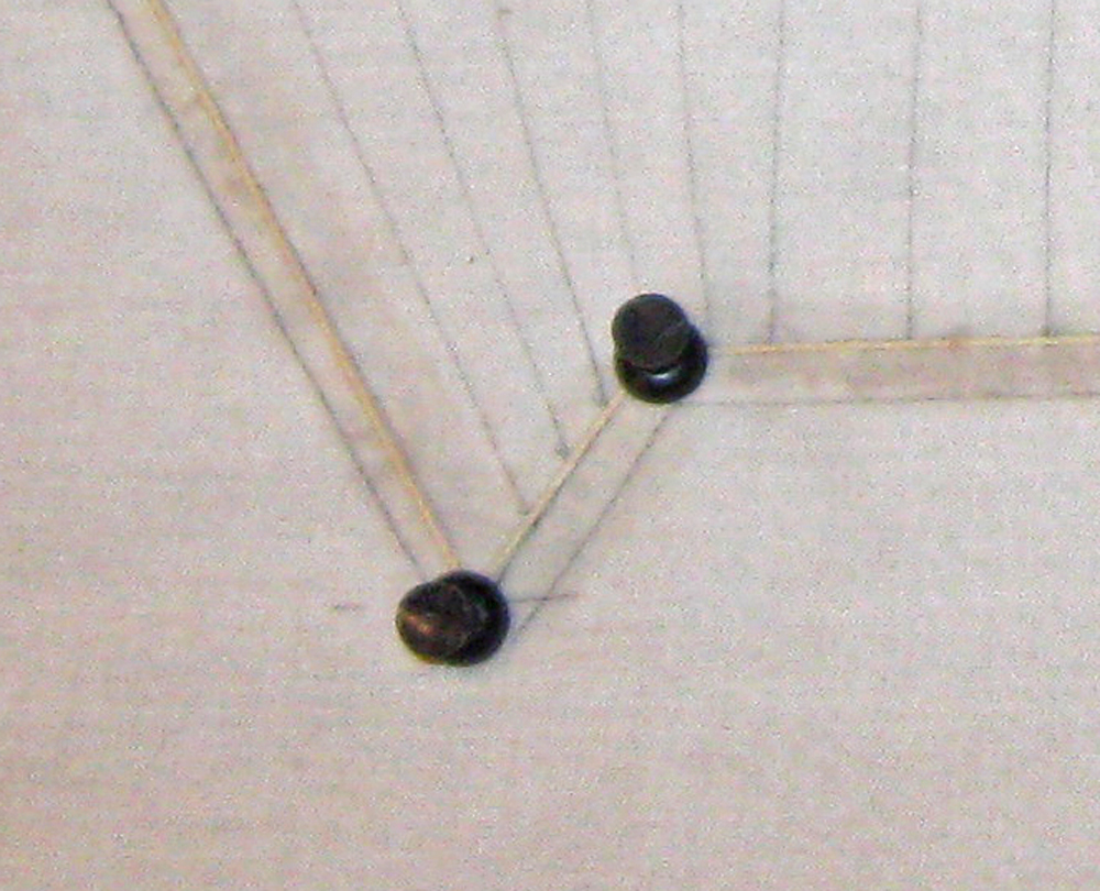
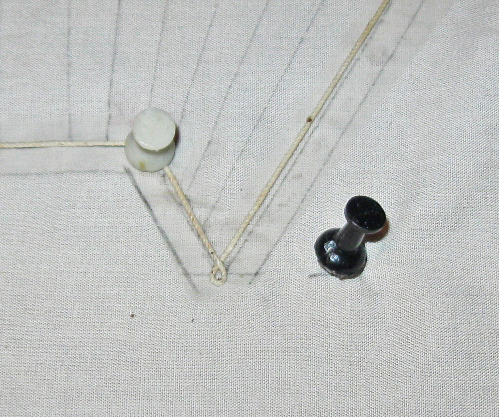
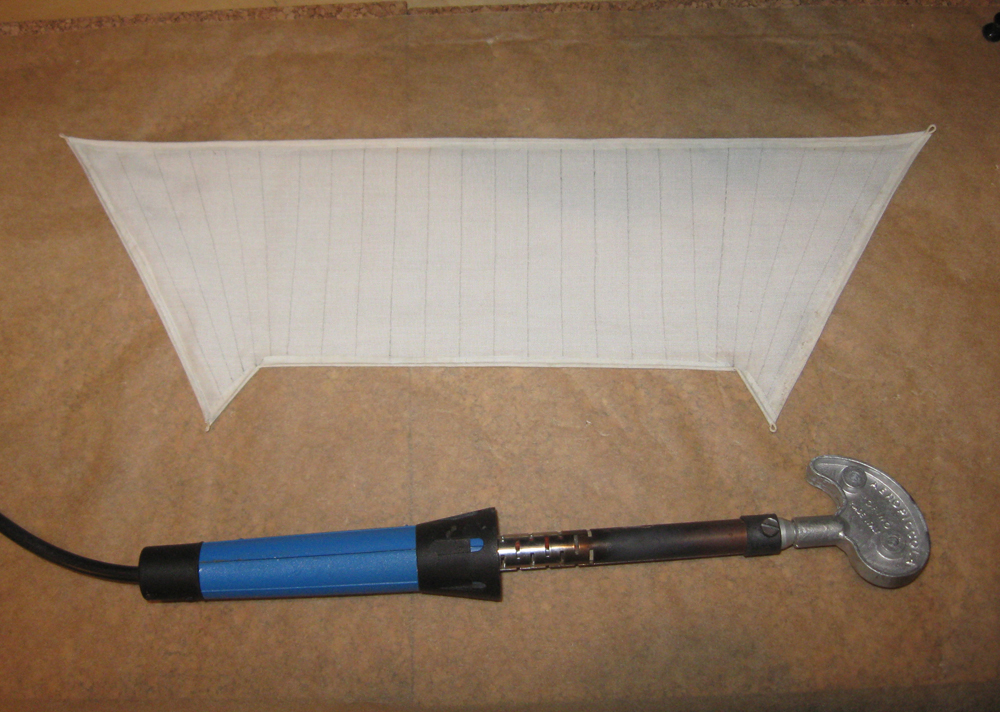
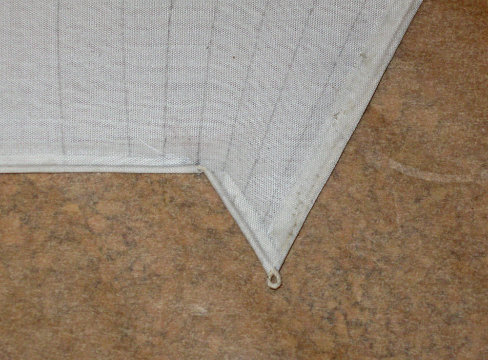
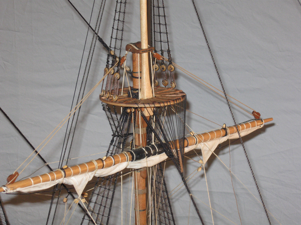
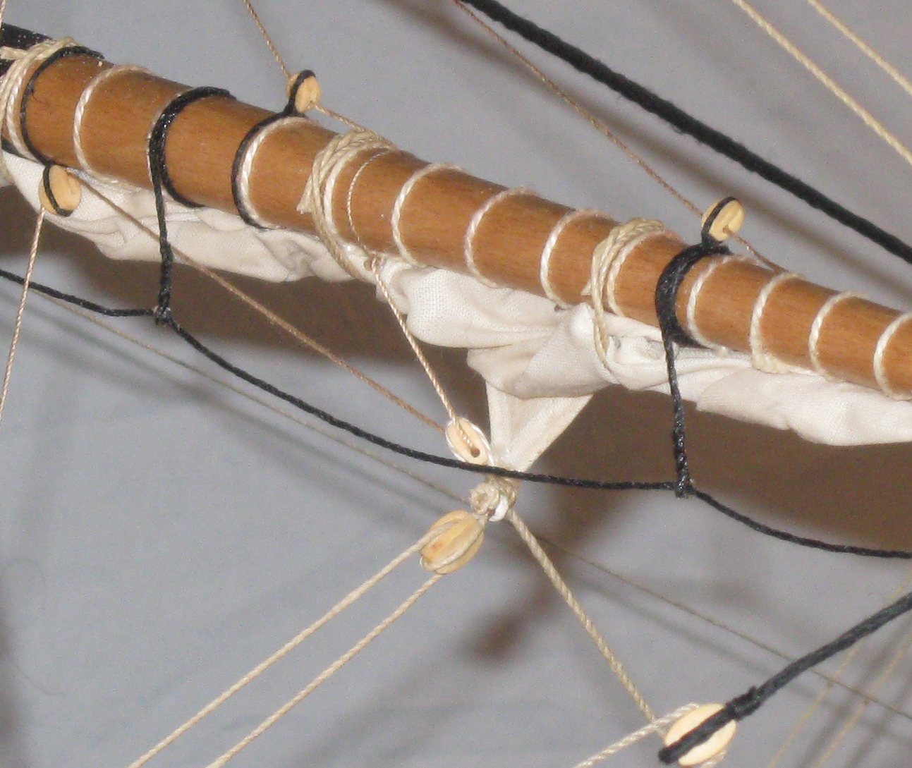
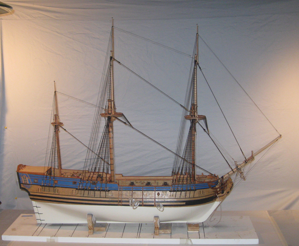
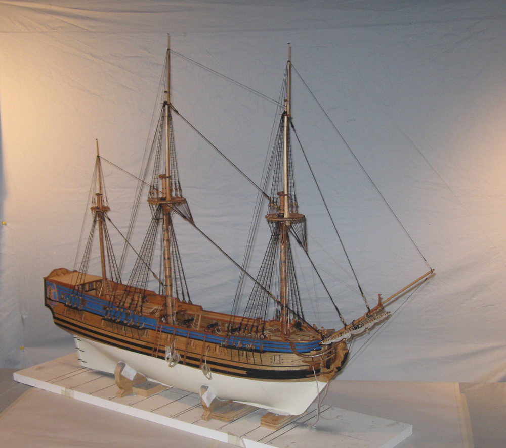
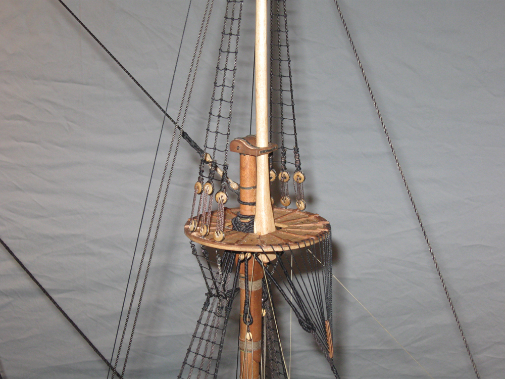
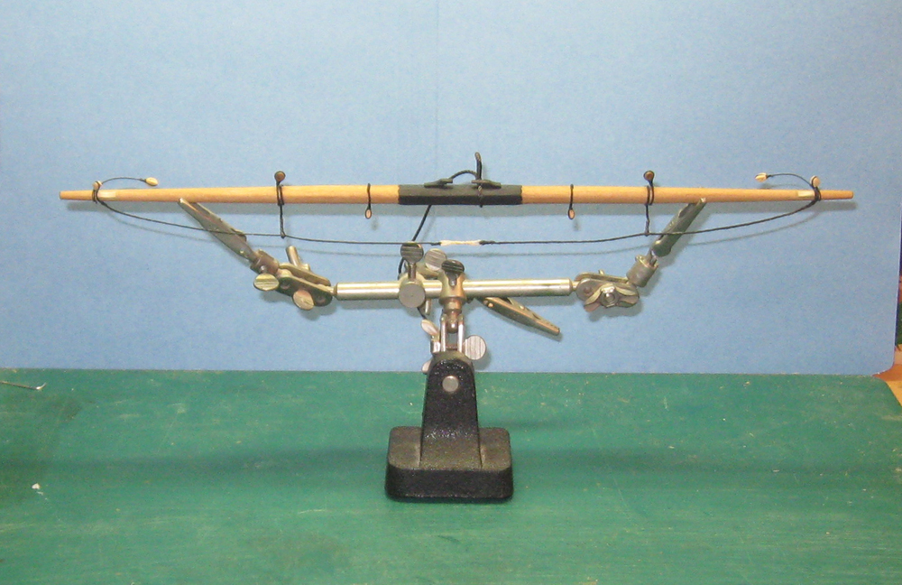
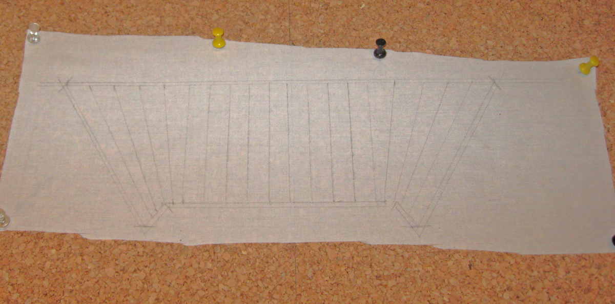
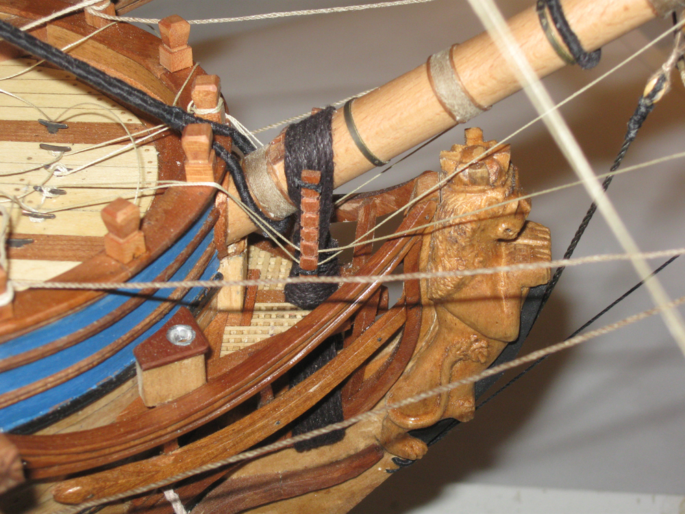
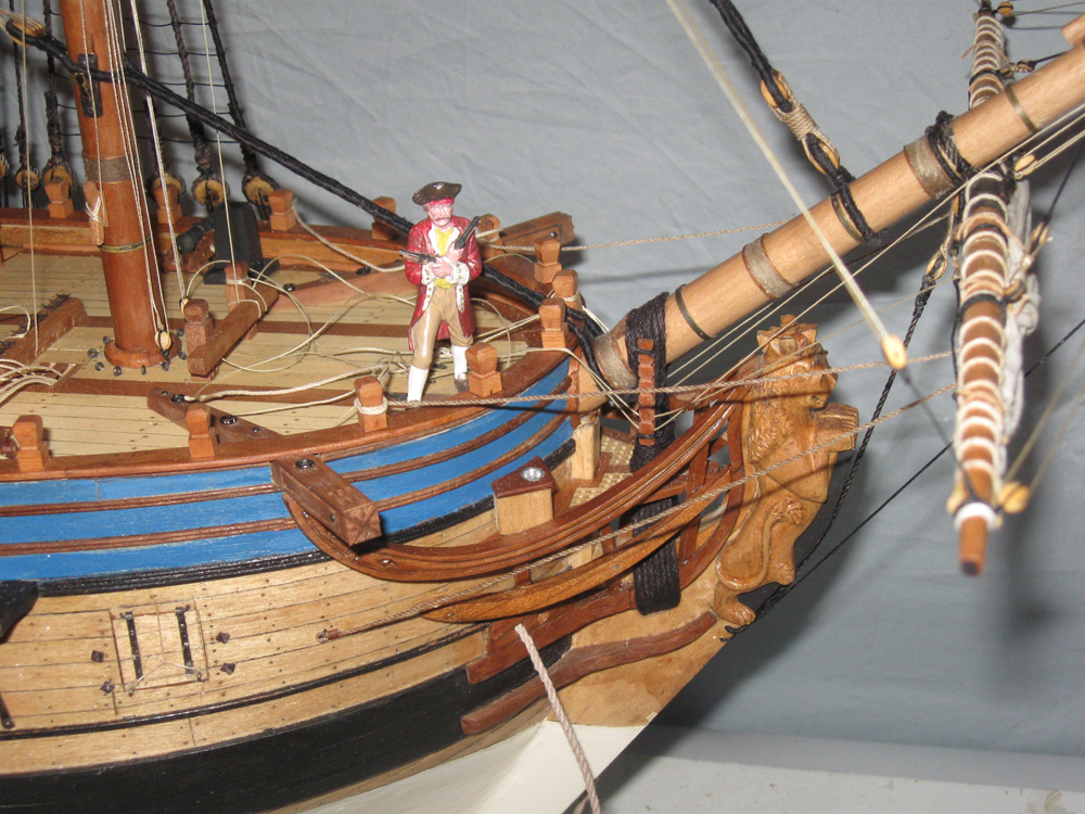
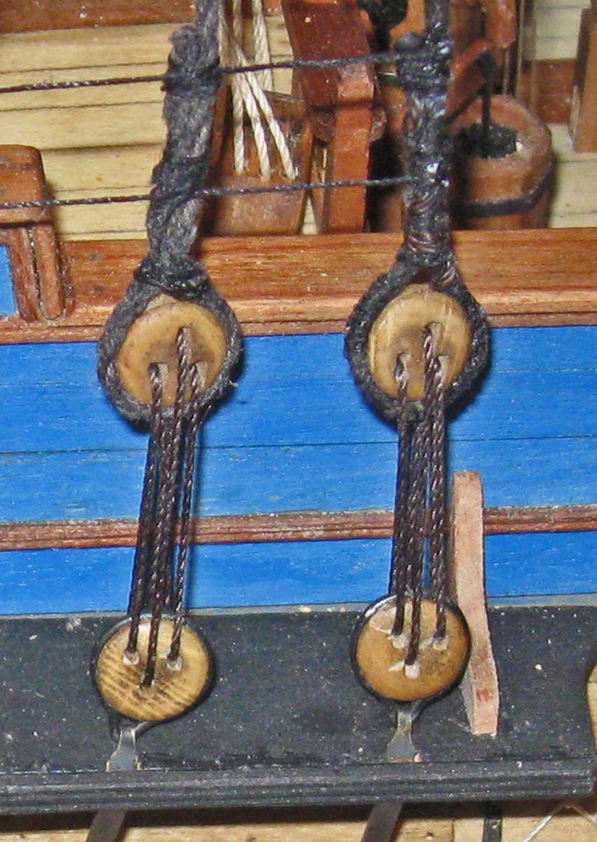
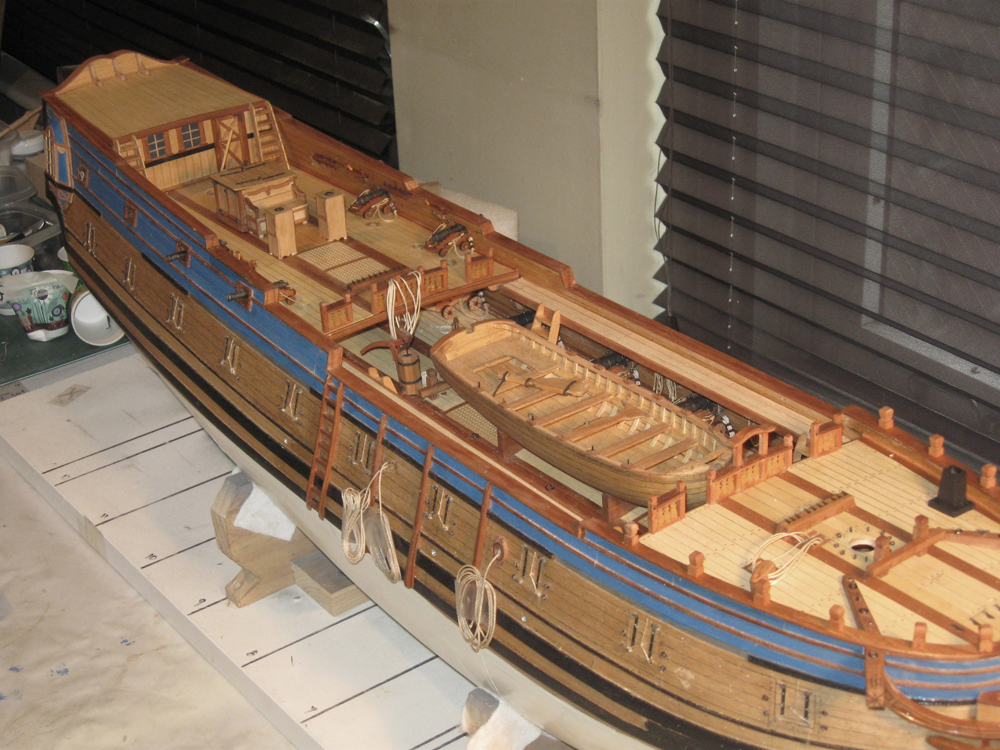
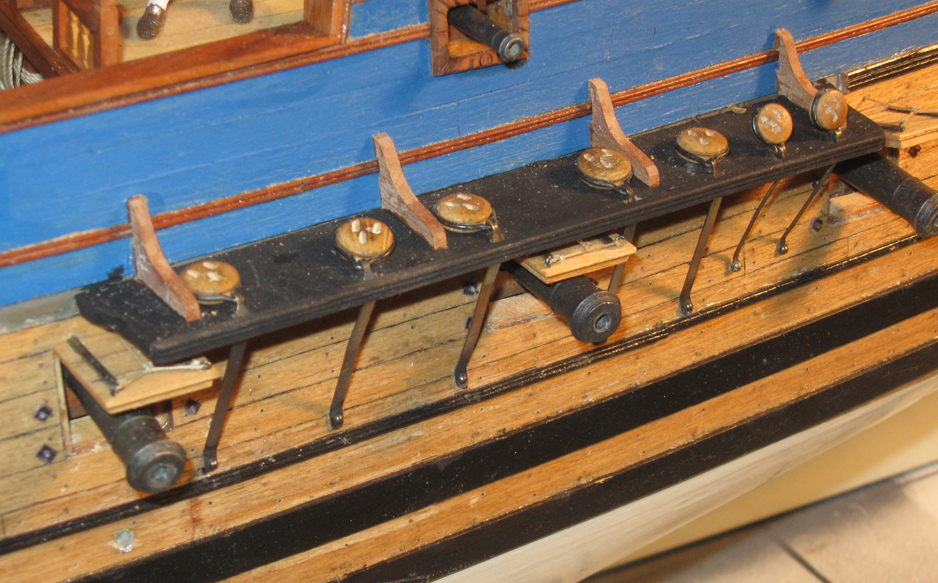
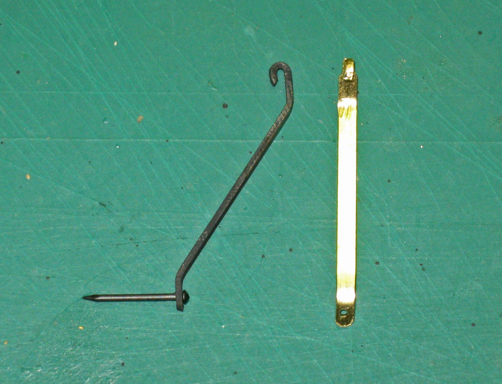
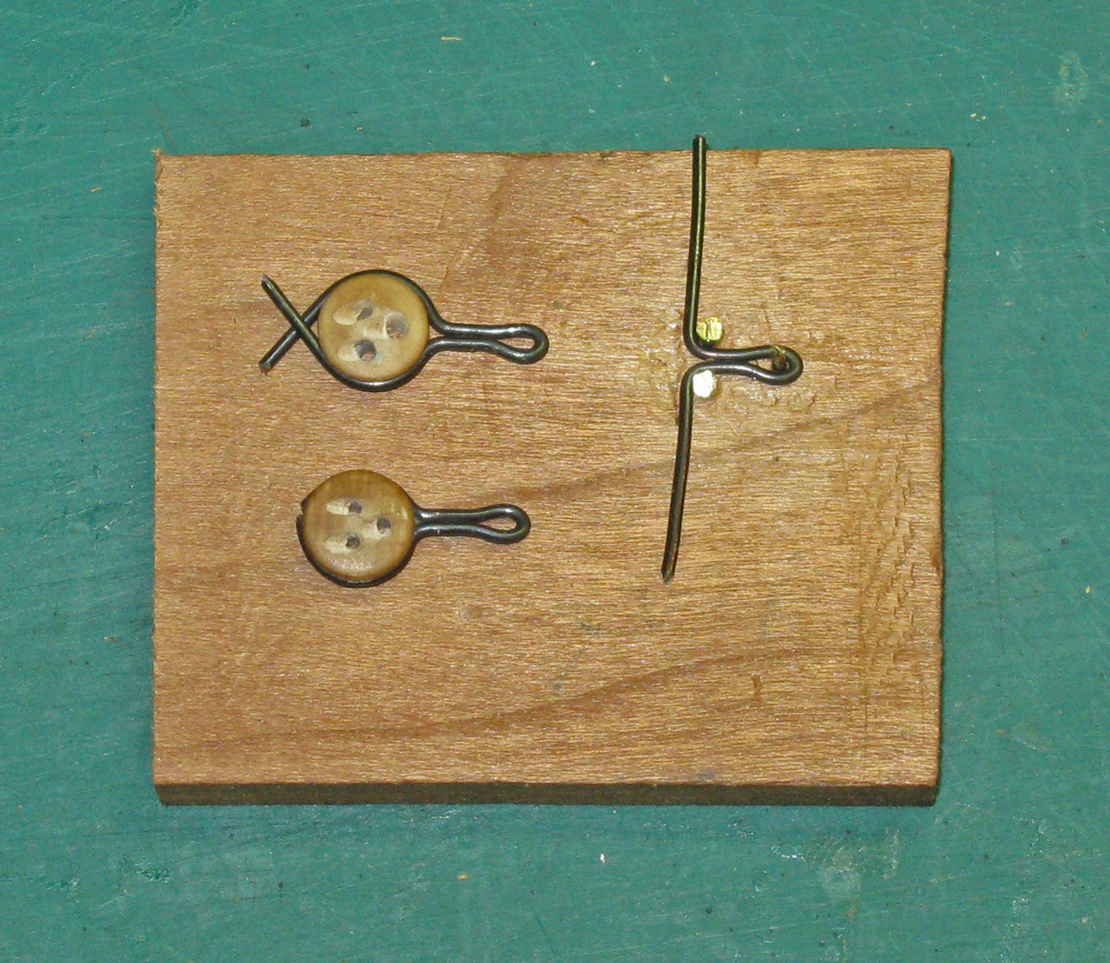
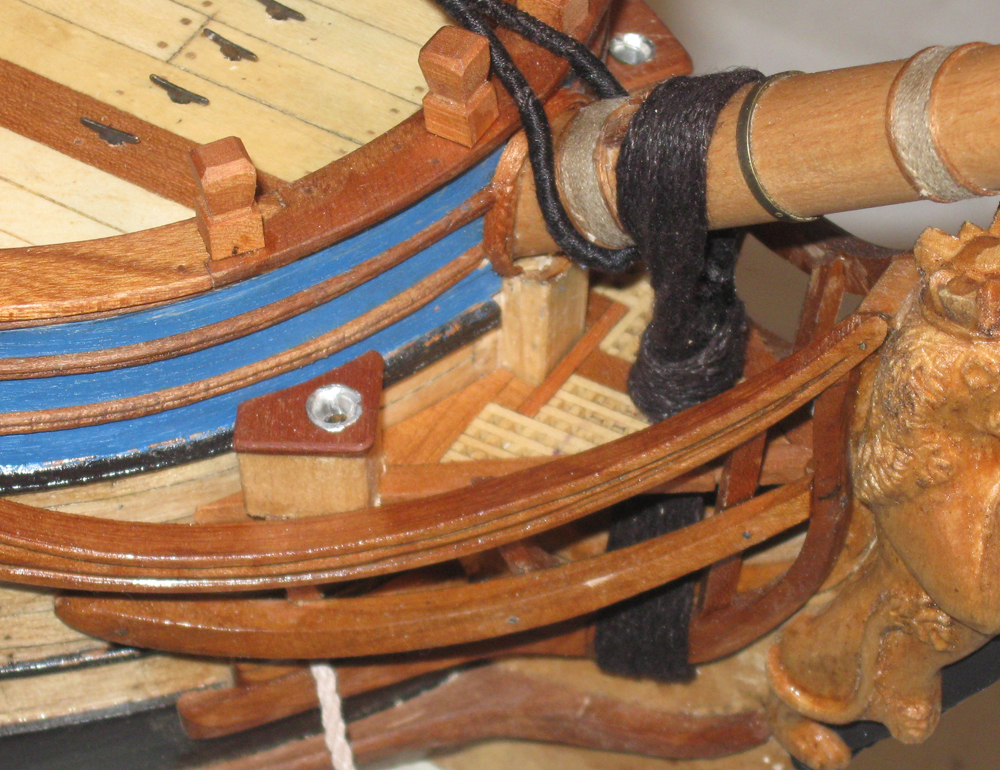
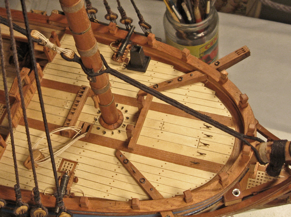
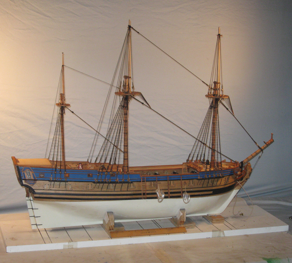
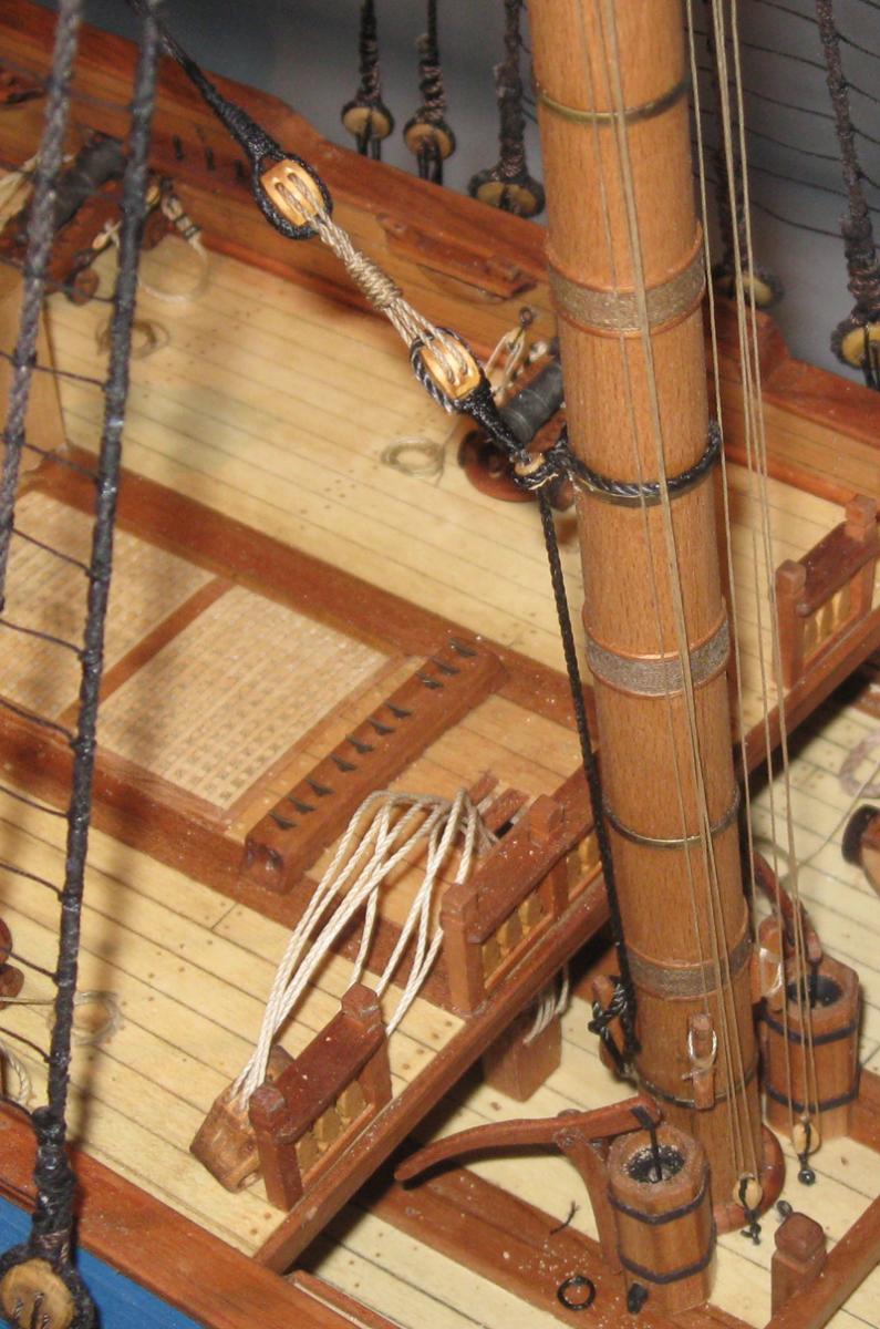
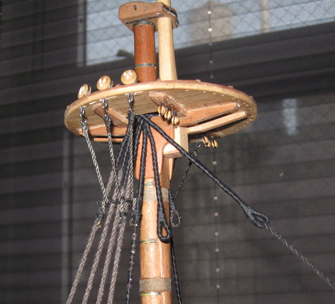
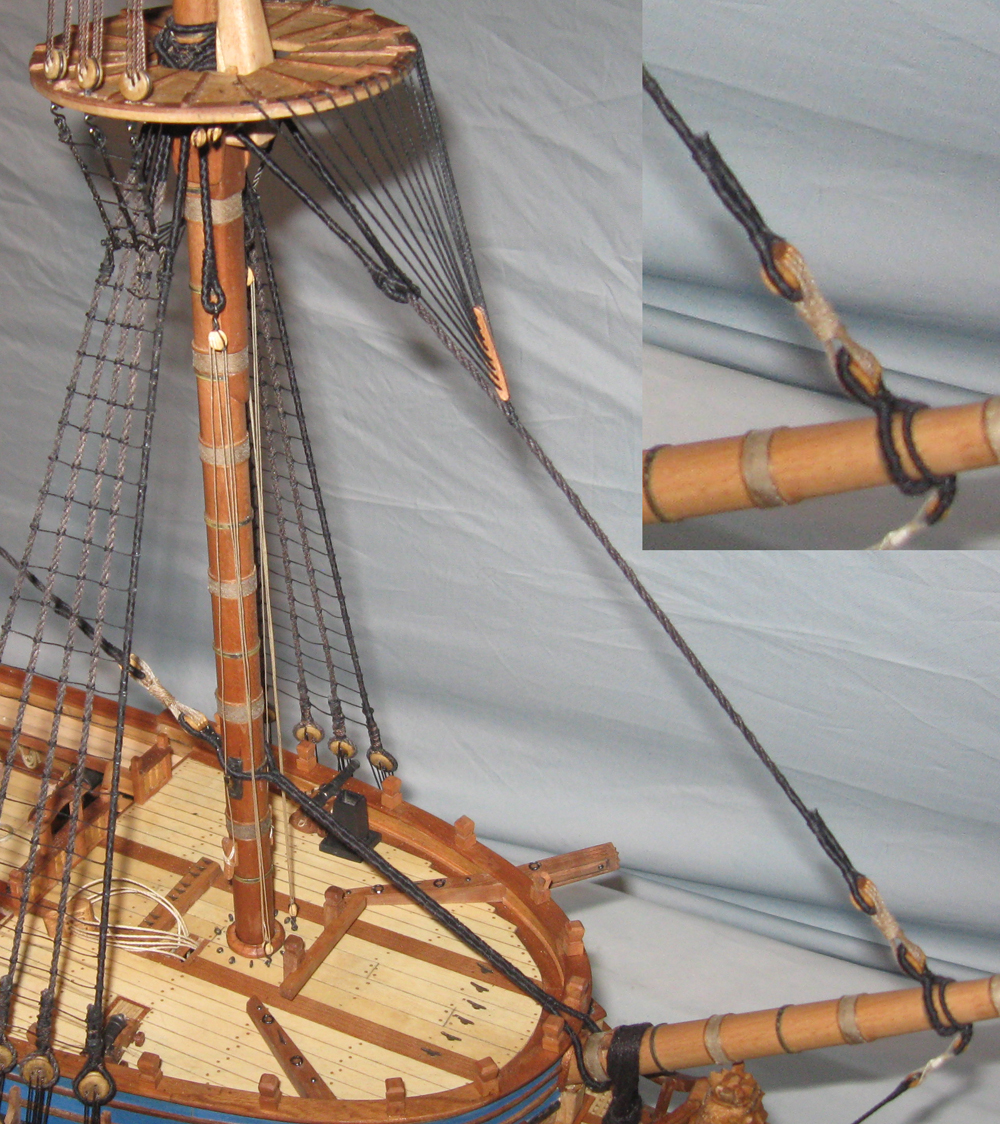
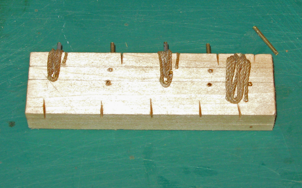
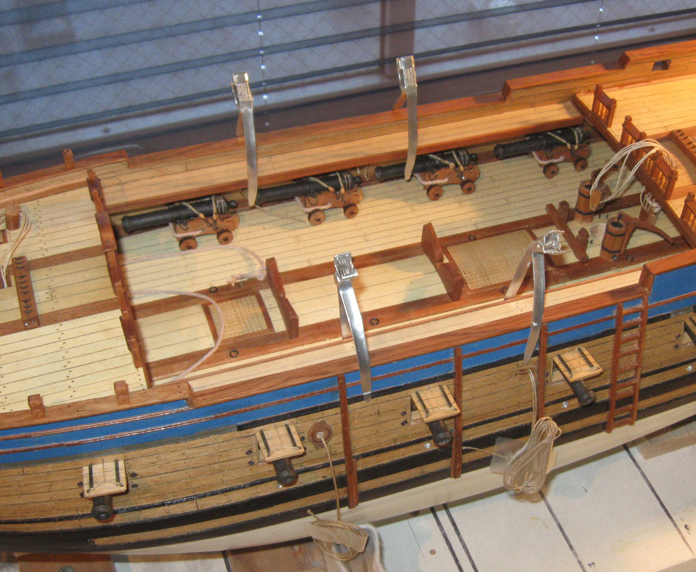
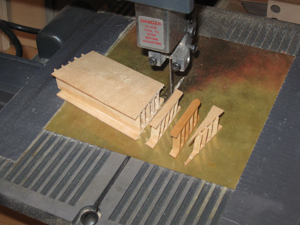
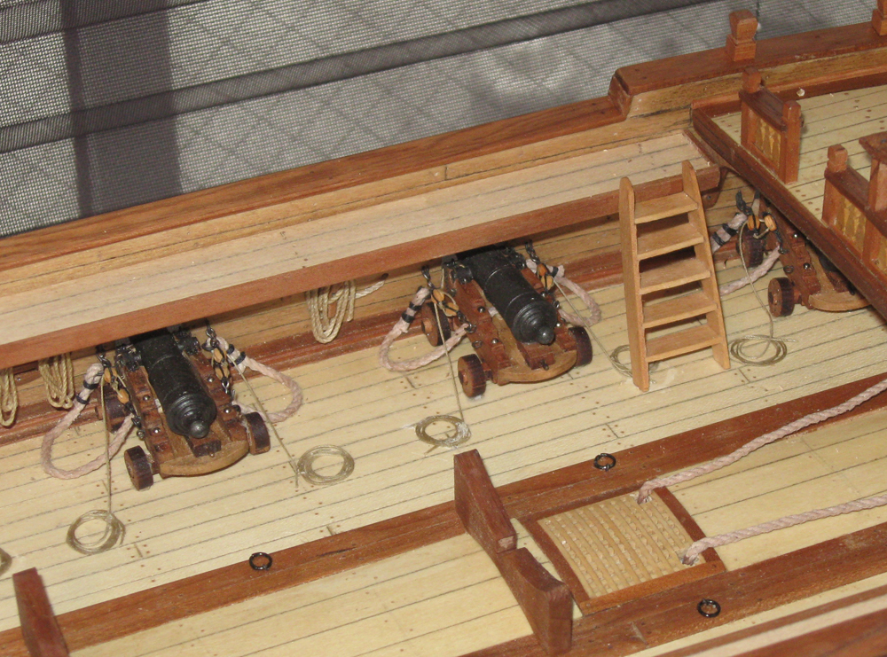
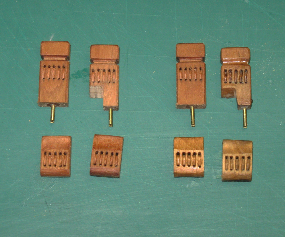
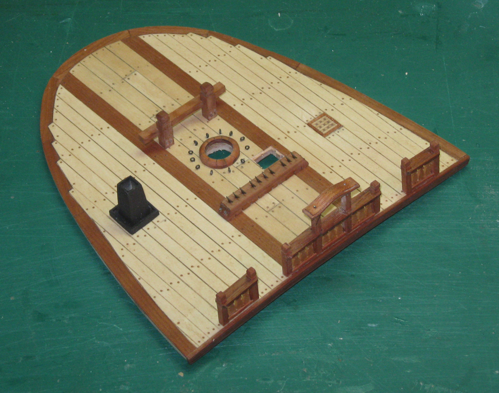
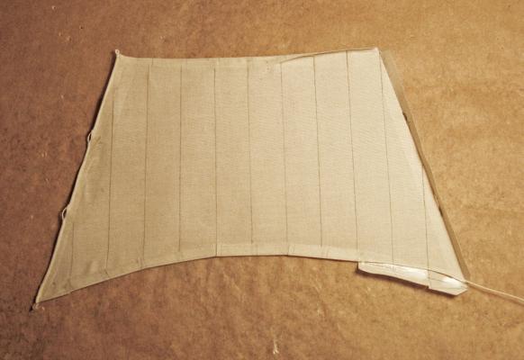
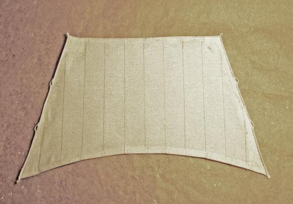
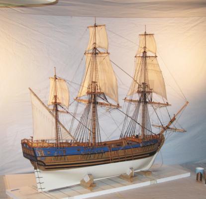
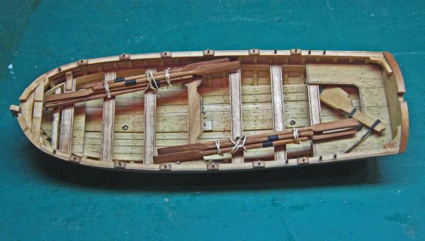
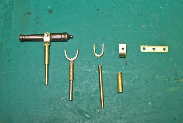
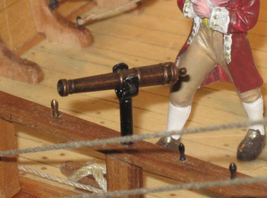
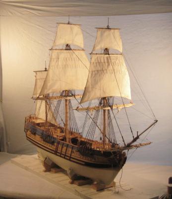
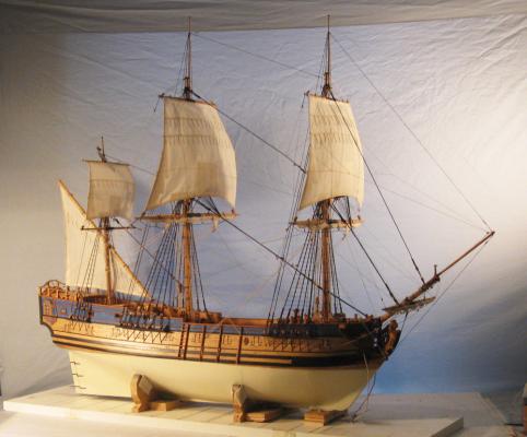
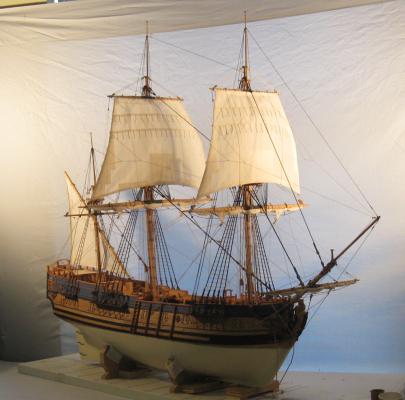
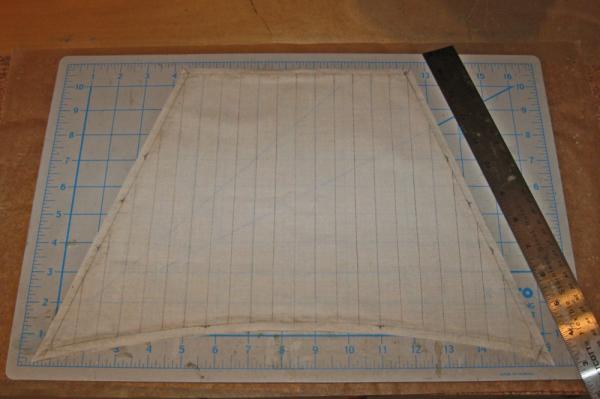
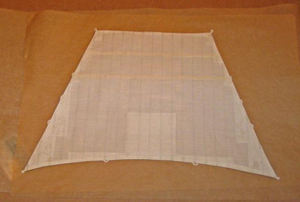
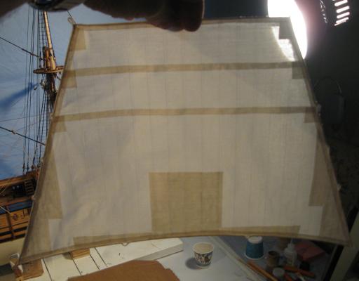
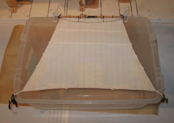
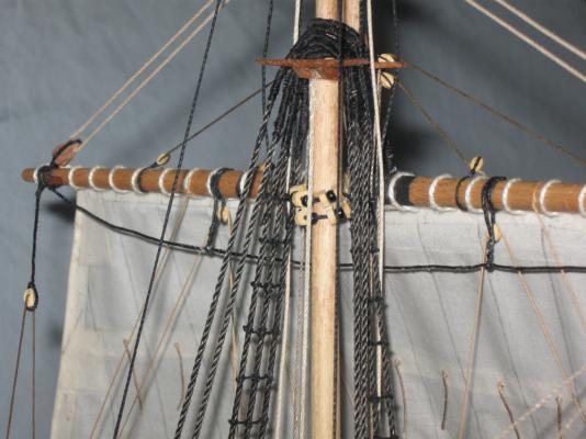
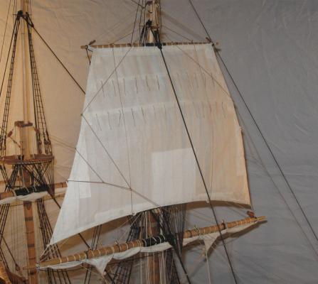
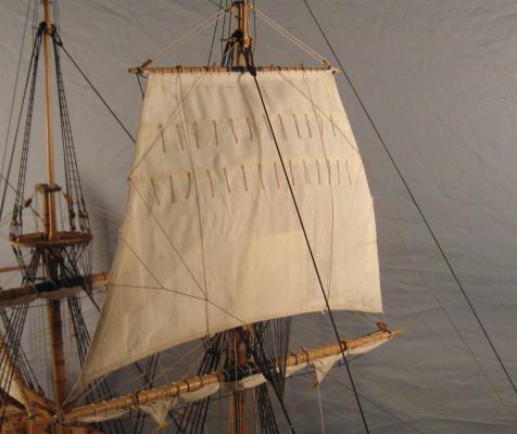
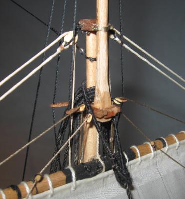
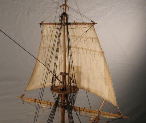
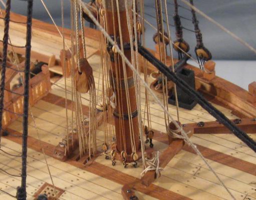
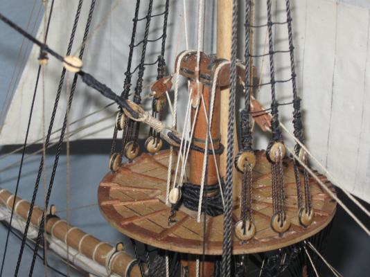
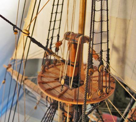
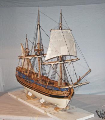
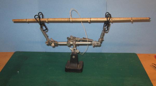
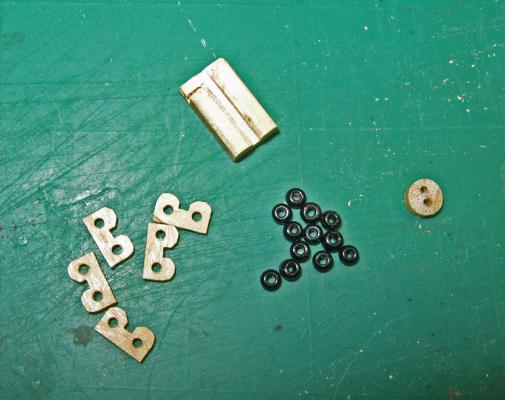
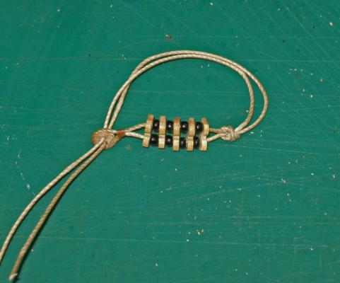
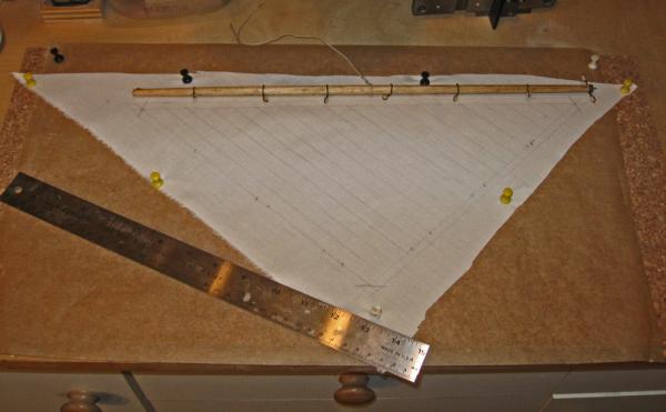
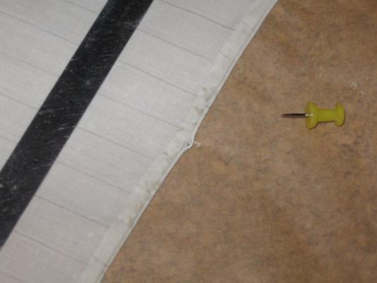
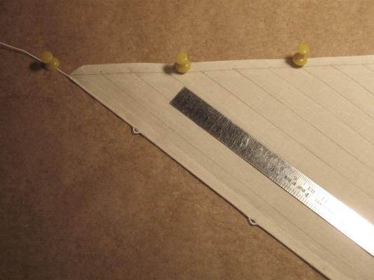
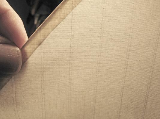
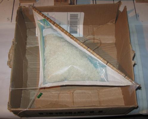
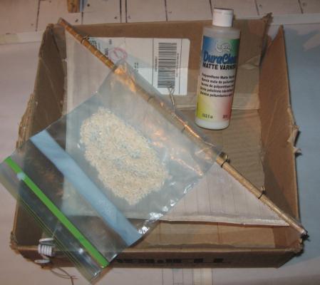
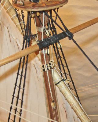
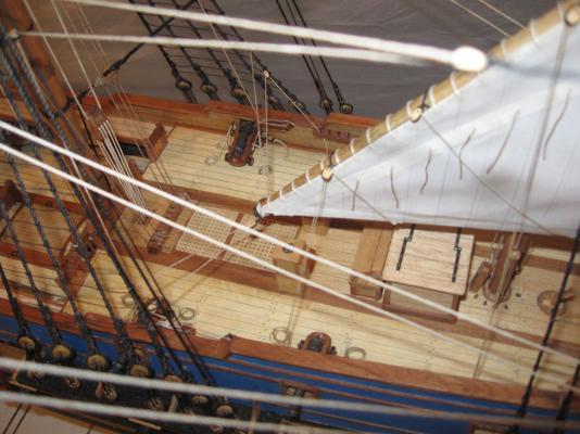
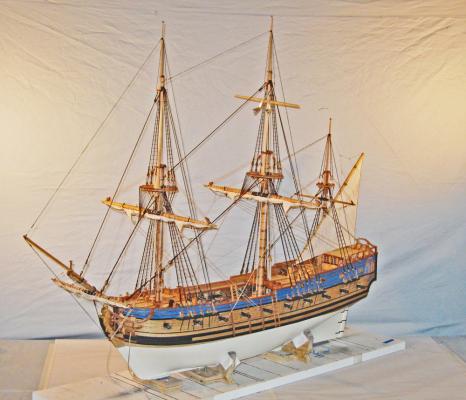
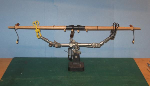
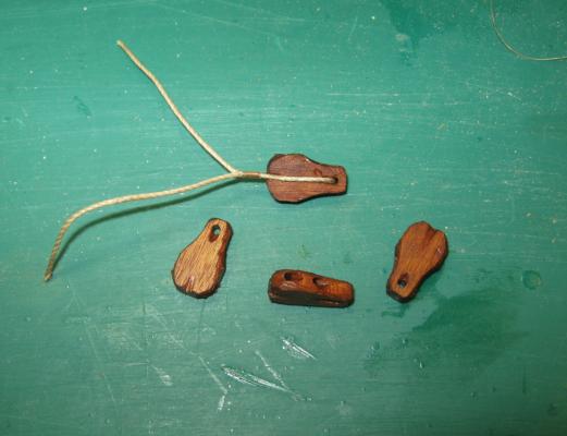
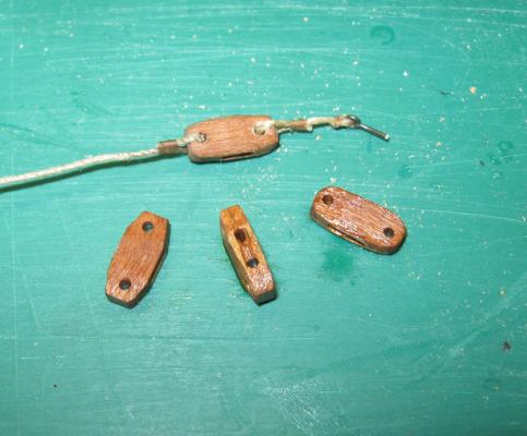
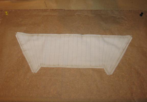
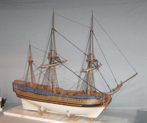
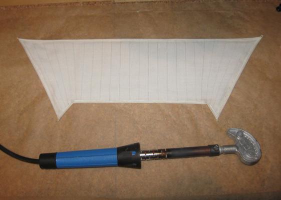
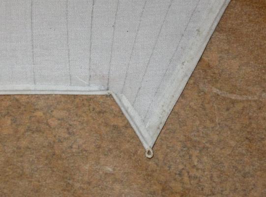
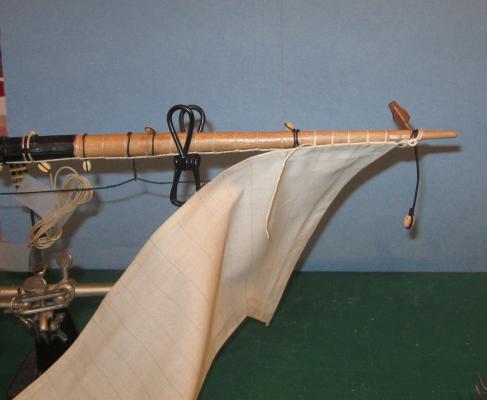
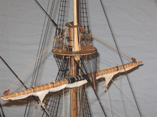
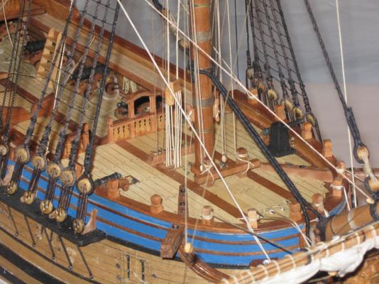
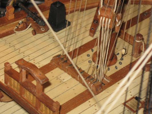
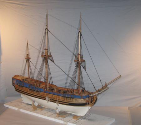
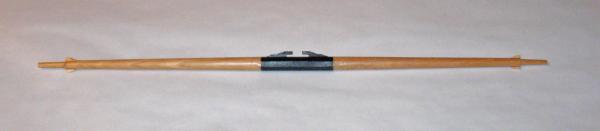
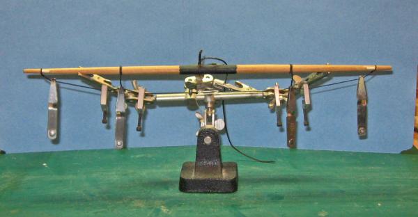
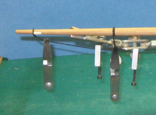
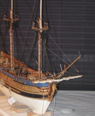
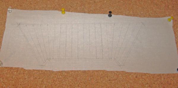
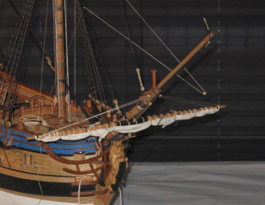
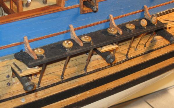
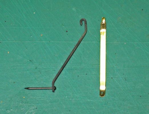
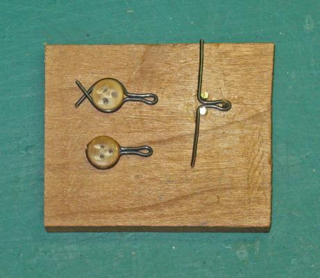
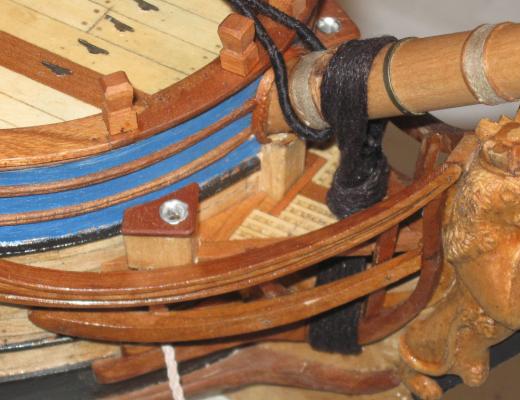
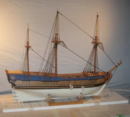
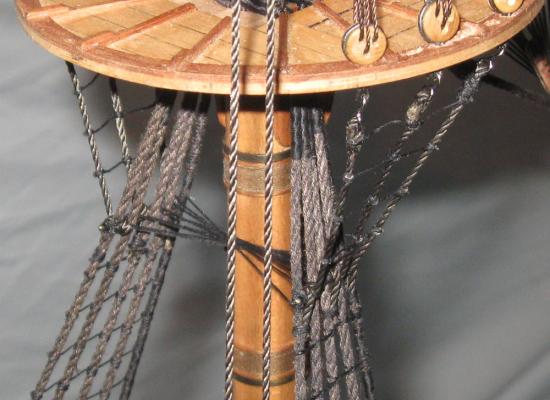
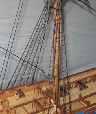
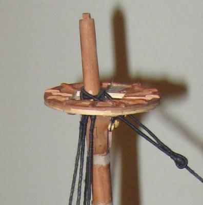
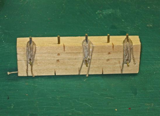
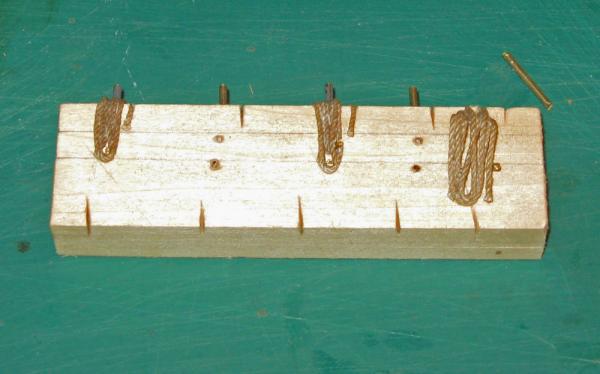
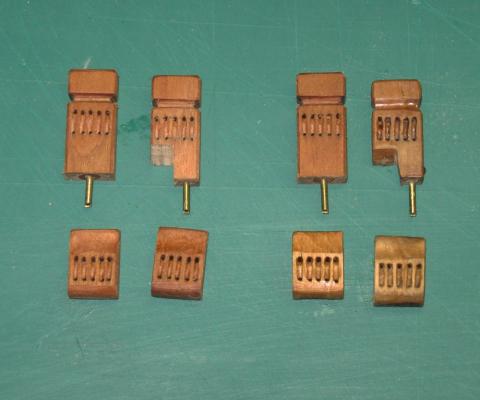
 Build Log 35 - t'gallant sails, boat, swivel guns Hi again, and welcome to spring - Back from vacation and back in harness. This installment finishes the square sails, the two topgallant sails; fits out the ship's boat and installs the swivel guns. The t'gallant sails were made using the same techniques as those for the larger sails. The sail was measured to fit the spar and reach the sheet blocks on the topsail spars. This was laid out on stiffened fabric. 1 The edges were glued, including the overlaps for the tabling. The openings for the cringles were cut out and the sail was cut along the outer edges of the tabling. 2 The bolt rope was installed and the tabling ironed down over it to secure it. 3 And here is the finished sail with reinforcements added to each corner. 4 The sails were laced to their spars and mounted to the model with ties and halyards, parrells, lifts, braces, and sheets, all according to Anderson. Clew blocks and lines were rigged and run, although these sails did not have buntlines or leach lines. Finally the bowlines and their bridles were rigged and run. 4a These last lines were pretty hard to run. Not only is it getting pretty crowded at the bases of the masts, but it usually took several attempts before I could make the lines run without fouling any previous lines. Here is what the foot of the foremast looks like at this stage. 4b And here is the model with all square sails set. 5 6 Next the ship's boat was fitted out. First came the oars. I made 12 of them to match the number of oarlocks on the sheer. In the photo you can see the four steps in their construction. The first three on the left are cut out roughly on the table saw. The next three have been roughly shaped using a sanding drum in the Dremel. The next three have been smoothed and refined, with a groove which sets off the handle. The final three have been final sanded, finished, and have had a rope sleeve added which would protect the oar from chafing on the rowlock. 7 Once the photo was taken the full set of oars was finished, then tied into bundles of six and lashed to a thwart. 8 A simple mast was made up to fit in the mast step. A spar was estimated and a sail made up to fit, then laced to the spar. The mast and spar were lashed together and to a thwart. Several belaying points were set into the sheer for stays and sail handling lines. Here is the finished boat on its cradles, although not permanently secured yet. 9 The final fittings in this segment are the swivel guns. It is known that Blackbeard added a number of these useful weapons to the armament of the QAR, and one has been recovered in the excavation of the site. Taking its measurements, a set of bronze colored barrels were located in the aftermarket that closely matched the size and shape of the artifact. To mount them, a set of simple forked stanchions were made up from brass. Here are the various pieces and how they go together. 10 Once the prototype was acceptable, the pieces were soldered together, the brass blackened, and the barrels mounted. 11 There are four on each side on the caprails, and one each in the main and fore tops. 12 So here is the current status. 13 Next, the staysails and maybe the anchors. Be well Dan
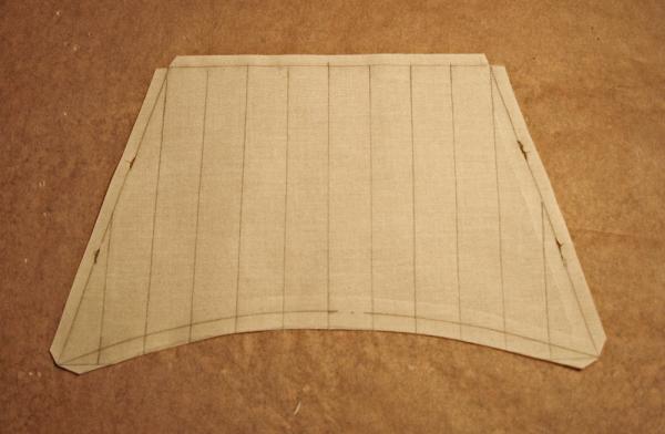


- 241 replies
-
- 12
-

-
- queen annes revenge
- pirate
- (and 2 more)
-
Bravo, Michael. Bravo. Dan
-
Michael - Such good news as I return. So glad your wife is better. The people we love are so much more important than the things we love, even ship models. Dan
-
Hi Nils - Thanks for the compliments. I just got a look at your Pegasus build. You are working in about half the size that I am, yet your attention to detail is just as complete. You are even rigging more staysails than I will. Nice work. David - Whether it will be at Mystic is open, but unlikely. The museum probably wants what they paid for. You would have to go to North Carolina for an in-person examination. Maybe the NRG will have a conference there in the near future. Dan
- 241 replies
-
- 2
-
-
- queen annes revenge
- pirate
- (and 2 more)
-
Hi David - All of the basic information was provided by the museum, both through their sets of digital plans and on their public website. The fine details, especially the rigging, has been much improvised. I am using the best secondary sources, but there are times when I have to shrug my shoulders and guess. Dan
-
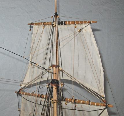
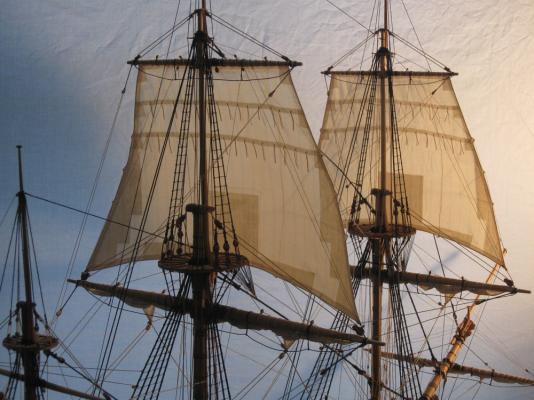
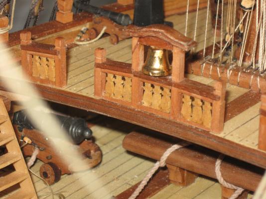
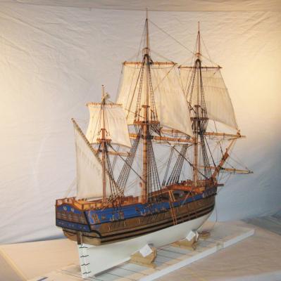
Build log 34 – main, mizzen topsail, bell Hi to all from snowy Brooklyn. I know that we have not had anything to compare with our daughter in Boston or son in Detroit, much less those of you who live in Canada or the northern tier of the USA, but between Brooklyn and Albany I have had more than enough of this winter !! So here is a quick update before SWMBO and I leave for a week on a warm island. The last segment ended with hanging and rigging the fore topsail. # Since then I have made, hung and rigged the main topsail. Nothing original here, just used the same techniques as on the fore topsail. 1 The pair look good, especially when backlit. 2 And here is the full model with the two large topsails. 3 One of the few details on deck that I had not done was the ship’s brass bell. One has been located in the excavation, so I had to include it. I hunted through all the usual sources, including several that said they had ones the right size. But when it came time to order them, there were none to be had. Finally a friend in the NY club and on this list, JerseyCityFrankie, found ones in a jewelry and beading supply house. Toho Shoji, Inc. has a lot of wire, threads, beads, and other items that can be useful. Check out their website at tohoshoji-ny.com. Anyway, here is the 10mm size installed in the belfry at the break of the foredeck. 4 I made the mizzen topsail, but have only hitched it to the mast with the parrell and the tye/halyard. I ran out of properly sized blocks from Warner Woods West, but Lloyd is sending me some more. The break therefore comes at a good time. So here is the model with the three topsails. 5 6 Thanks to all for likes and comments. Stay warm and be well. Back soon Dan


- 241 replies
-
- 17
-
-

-
- queen annes revenge
- pirate
- (and 2 more)
-
Thank you all for the likes and compliments. The ones that I appreciate the most are those about the teaching aspects of what I write. I hope that, like the model itself, the teachings will outlive me and be passed along. Matt - no weathering other than ordinary grime from the shipyard worker. If I started weathering, I don't know where I would stop. She had a hard, seven year career as a privateer and slaver before being captured by pirates. Although functional, I suspect that her appearance was closer to the Black Pearl than to the Victory. Dan
- 241 replies
-
- 1
-
-
- queen annes revenge
- pirate
- (and 2 more)
-
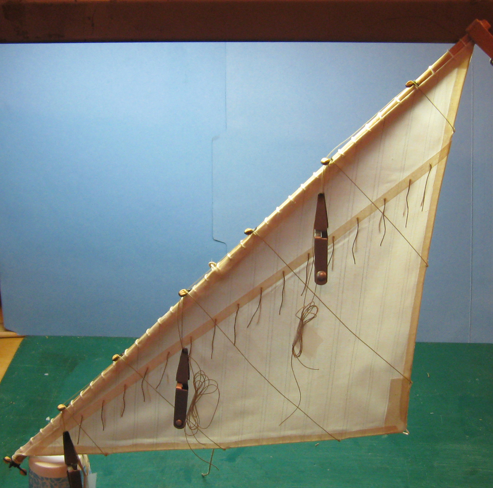
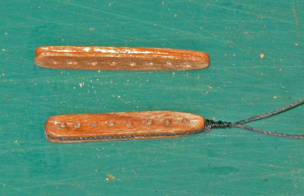
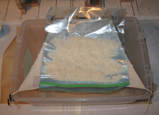
Log 33 – Fore Topsail Hello again to all. Since the last entry I have made and hung the fore topsail. This is the first of the square sails that will be shown set and filling, and took somewhat longer to complete due to my inexperience. I had to go back a few times to understand all of the lines and to work out some technical problems. Here is the yard, shaped as usual with cleats, stop cleats and blocks. At this point I still have to add the larger blocks near the center for the topgallant sheets. Also the stirrups and footropes. 1 The sail itself was laid out, like the lateen, on stiffened cloth. The panel lines and tabling lines were marked out, then the perimeter was painted with pH neutral white glue. When the glue was dry the sail was cut out and small triangle openings were cut along what would become the perimeter of the sail for the cringles. The sail was turned over and panel seams were lined on, offset about 3 scale inches to one side of the first set of seams. 2 The boltrope was set into the creased sail edge and trapped in place when the tabling was folded over and ironed closed. As with the lateen, the cringles were made by feeding a bend of the bolt rope through the previously cut openings to form the cringles. When the tabling was completely closed the various reinforcements were added to the back of the sail. These were made out of stiffened cloth that was marked with panel seams, if needed, then cut and glued to the main sail as shown on the plans. They were ironed down to the main sailcloth and should be very stable and secure. On the front of the sail two bands of reinforcement for the reef points were similarly cut, glued, and ironed. 3 Here you can see all of the elements of the sail, backlit and translucent. 4 A series of holes was drilled through the tabling along the top of the sail with about a 3/8” spacing. A continuous series of loops was sewn through the holes to lace the sail to the spar. Then it was set into a large plastic tub for stiffening. 5 The sail was painted with clear matte finish and weighted with about half a cup of rice in a plastic bag. It was left to dry overnight and, once removed from the jig, had a pleasing catenary curve to the three free sides. 6 Holes were drilled through the reef bands and the reef points were knotted, glued into the holes, and trimmed. Matte finish was painted on to hold them down on both sides of the sail. Clew blocks were tied to the lower corners and the sheets were knotted and laced through the clew cringles. The sail was hung on the mast and the parrell was strapped around the mast and yard. In the photo you can see the running ends of the topsail lifts (the heavier light colored lines) are hanging down and have not been belayed. There are clips on their lower ends to provide some weight and tension on the system to keep things from getting tangled. The clips also remind me which lines have not been belayed yet. 7 The tie with its fiddle block already seized in was fed from aft to forward through a sheave hole in the mast under the trestletrees. It was taken down around the yard and attached with a rolling hitch. The fiddle block at the running end of the tye is the top of a three part purchase hooked into an eyebolt in the top. The halyard belays to a cleat on the mast near the deck. 8 The lifts were laced through the fiddle blocks at the yardarm and led down towards the deck through the lubber holes, but not yet secured until the sheets were led through the sheet blocks on the main yard then down through the sheaves in the bitts forward of the mast. Then both sets of lines could be tensioned against each other. The braces were run from the main topmast stay, through several sets of blocks to a timberhead on the edge of the foredeck. They can be seen in some later photos. That completed the spar handling lines. The sail handling lines were then run, which completed the rigging to the topsail. Here is the sail fully rigged as seen from forward. 9 In this view the lighting was varied so the sail handling lines can be seen a bit clearer. The fore topsail, like the other square sails, has p/s pairs of clewlines, leachlines, buntlines, and bowlines. Eight more lines for each sail. I had never previously fully rigged a ship, and the level of complexity with all these lines is a real eye-opener. The bowlines start as a triple bridle from the cringles on either side of the sail. They lead to blocks on pendants at the end of the bowsprit, then aft through the gammon blocks and up to cleats on the foredeck. The buntines lead from cringles at the foot of the sail, through lead blocks on the yard, through blocks strapped to the topmast stay, and then to the deck. Similarly, the leach lines run from the upper side cringles through lead blocks and down to the deck. 10 In this closeup of the masthead you can see those lead blocks on the yard and stay. 11 From aft in these two views you can see the braces and clewlines. 12 13 Each of the sail handling lines goes down to a tackle hooked to the eyebolts around the base of the mast. It is starting to get very crowded here. The halyard is belayed to the mast cleat with several turns of line and a yacht hitch, but no glue. All of the belaying points will be painted with matte finish only after they are all done. 14 I try to leave extra line on the belaying point and delay the final securing till very late so that when, not if, I make a mistake I can correct it more easily. For example, here is the first photo of the halyard tackle on the mast top. Looking at it I could see that the halyard was running through one of the side lubber holes and made a fairly acute angle as it went through the lubber hole to the deck. Such a kink is a mistake. 15 In most cases this would be difficult to correct. Instead, I just had to untie the halyard from the cleat and re-run it properly, belaying it to the cleat again. Although it took some finicky work with two tweezers, it only took 15 minutes, not an hour. A very small point, but one that would have nagged at me at 2 am. 16 So here is the current overall look. 17 Main topmast next. Be well Dan

- 241 replies
-
- 12
-
-
- queen annes revenge
- pirate
- (and 2 more)
-
Hi all - Hold the applause. There's a long way to go before the fat lady sings. But thanks all the same. Mark - you could very well be right. As I was putting the lateen on I tried a number of ways to get the heel from port to starboard, and had no end of trouble. I have never seen a satisfactory explanation of the maneuver. A hauling point on the lower end of the spar makes a lot of sense. Dan
-
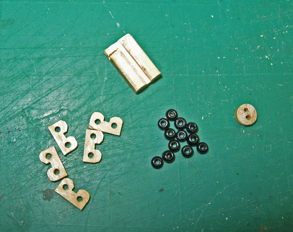
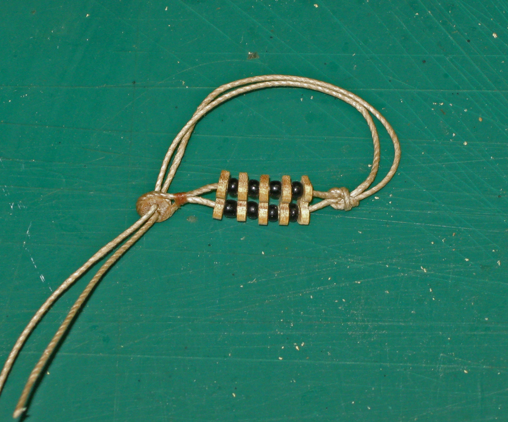
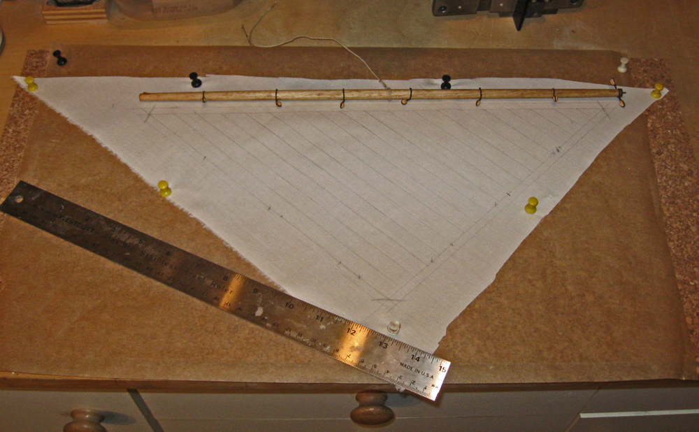
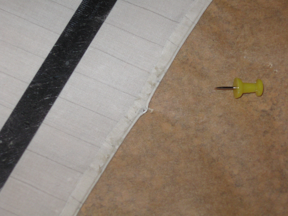
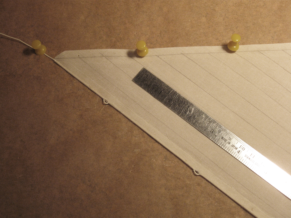
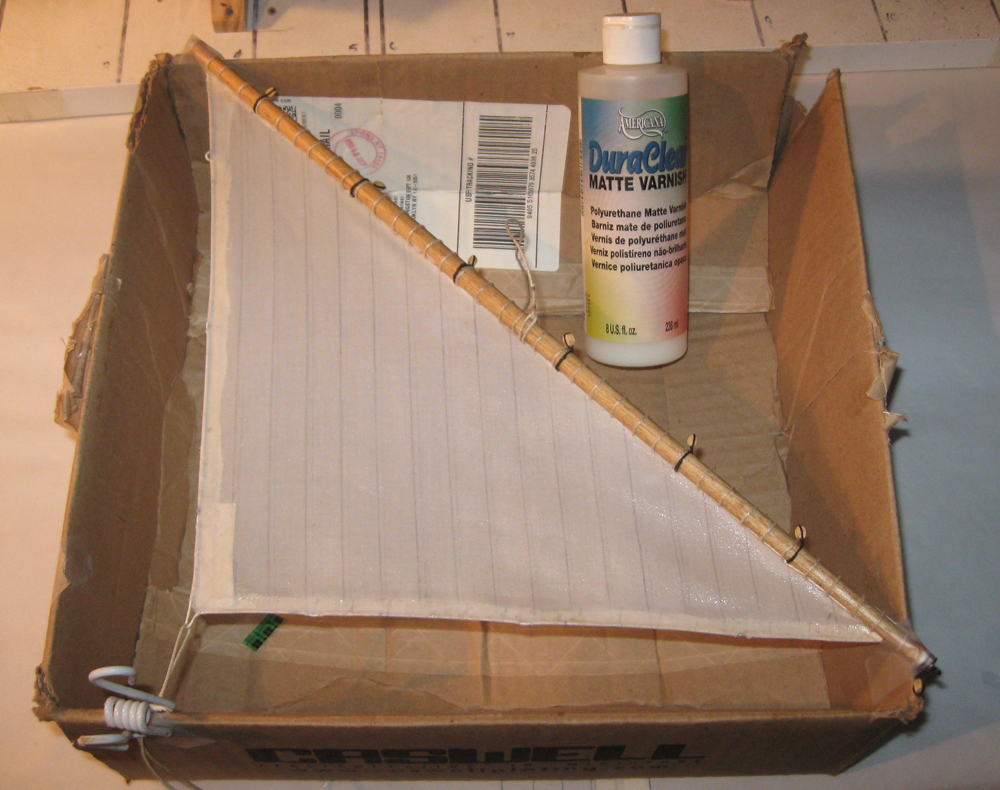
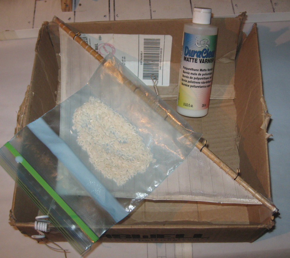
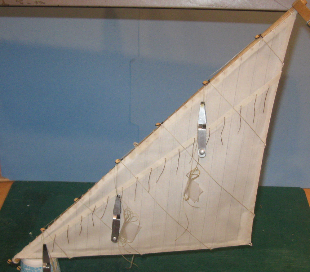
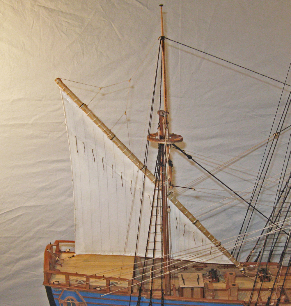
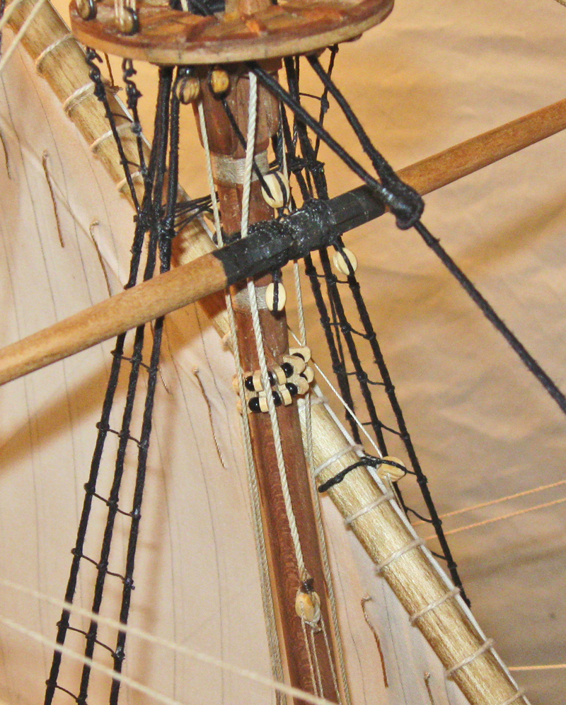
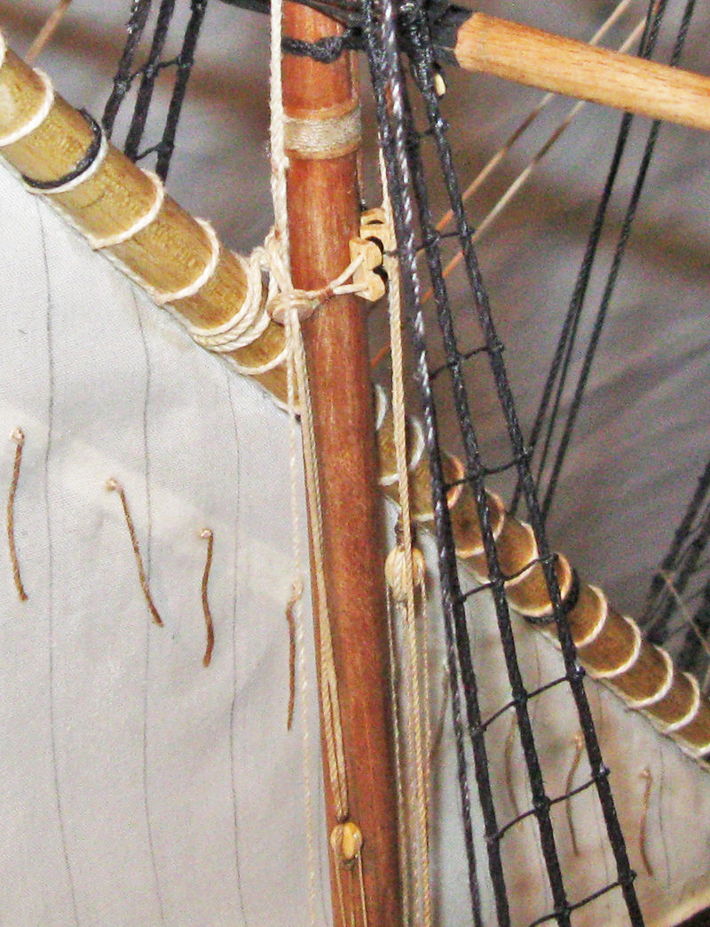
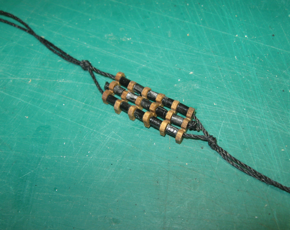
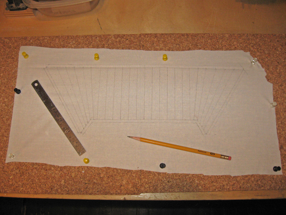
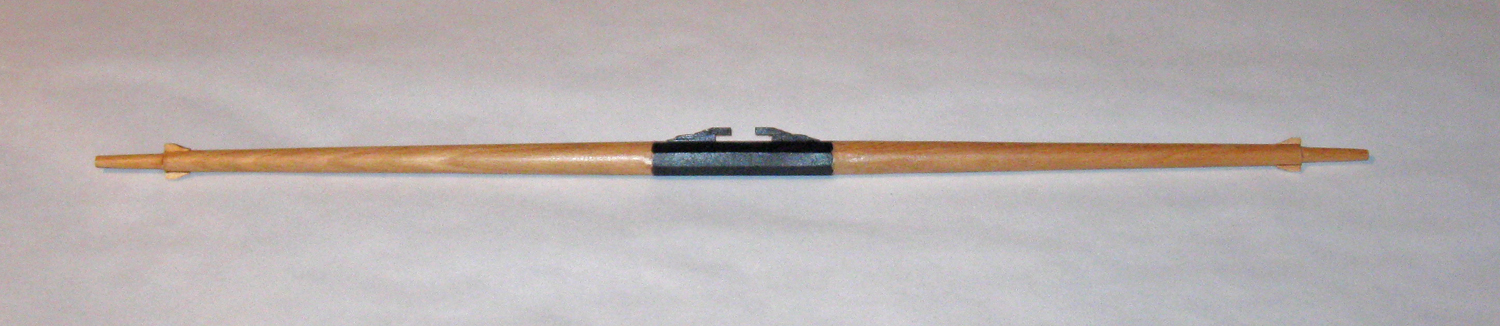
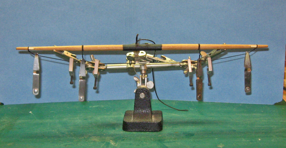
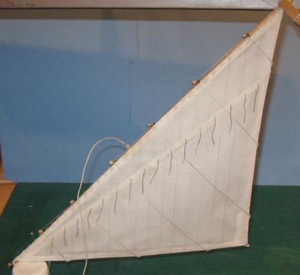
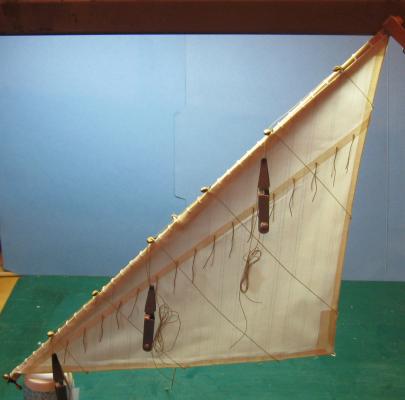
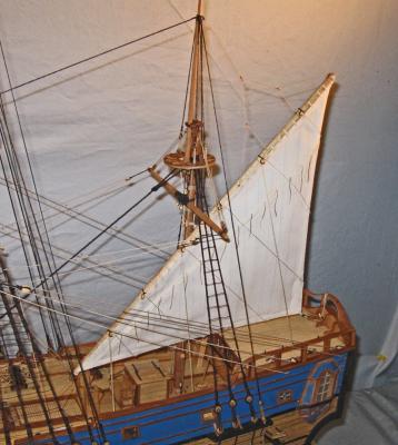
Build Log 32 – crojack and lateen sail Hi again. Being snowed in here in NYC had the silver lining of giving me some extra time to work on the model, so here is the next installment. The next spar to be tackled was the crojack yard on the mizzen. Even as far back as 1710 it did not carry a sail, but was there to spread the foot of the mizzen topsail. It was shaped in the usual manner to the Budriot plans. Since it does not carry a sail the number of blocks stropped to it is reduced. There are sister blocks at the yardarms for the lifts and mizzen topsail sheets, pendant blocks for the braces and sheet blocks under the yard near the center. Since the yard is not lowered with any frequency, the parrell is replaced by a static collar, with the yard having a single large block in the center that will hold a sling that circles the masthead and supports the spar. Here is the spar ready for mounting. The sling has been turned round the spar on one side and sized to the mast, leaving two long legs to be hitched round the spar and trimmed. 1 Here is the crojack yard mounted. In the enlarged portion you can see the collar hitched around the mast and spar and the sling running through the center block. According to Anderson (who I mistakenly referred to last time as Andersen) the French used the same lifts here as on the forward masts, while the English had already turned them into non-moving standing lifts since the yard did not move up or down. 14 In the above photo you might notice that there is now a railing around the poop deck/roof of the captain’s cabin. In testing the fit and location of the lateen sail I realized that there were no belaying points anywhere at the stern of the ship. Some belaying pins will be added to these rails, and other lighter lines can be hitched to the rails without pins. The posts will also give me some future locations for swivel gun mountings. They are 3 feet high in scale and made from steam bent pear, like the caprails. 15 The lateen spar is the simplest on the ship, even more so than the crojack yard. It tapers to both ends, but without a center octagonal section. There is a metal reinforcement and eyebolt at the lower end, but I never did discover the use for that fitting. A halyard line hitches to a point near the center of the spar, but a little towards the upper end. I left it loose until the yard was finally mounted. Along the length of the spar are six small blocks. They are for the brailing lines that furl the sail and take the place of the clew, bunt and leach lines. They alternate single and double blocks, which will be made clear later. 16 The parrell is made up of “B” shaped spacers and black beads. The final piece is a small deadeye with only two holes. 17 Here is how it goes together. The deadeye is seized into the parrell line which doubles and laces through the spacers and beads. The lines are seized together again, although I took a shortcut and knotted them so I could adjust the placement later. The knot will be invisible in the final mounting. The lines then loop around the mast and the base of the halyard before threading through the deadeye. The parrell does not go around the lateen spar, but holds the halyard close to the mast instead. I read Anderson’s description of this many times before I began to understand it, and I am not really sure that I fully get it even now. 18 The lateen sail started by being laid out on the prepared sailcloth. All of the panel lines are parallel to the cloth threads, although the lower corner is not precisely a right angle. 19 Since the sail will be set with all its lines, I had to develop cringles at the edge of the sail as attachment points for the brailing lines. For my first attempt I cut small openings in the fold of the tabling, then laid the bolt rope into the fold and glued it as before. With a pin I reached in and pulled the bolt rope out of the opening. This did not work too well. The rope was fixed in place, so pulling it out made a visible kink in the edge of the sail. 20 For the next effort I worked the bolt rope into the cringle openings as I ironed down the tabling. This was a much more successful effort, although it took a significantly longer time. 21 Once the tabling was all down I turned the sail over and marked the panel seams. I found that the cloth was thin enough that a piece of white paper placed under the sail allowed me to see the panel seams through the cloth. Then the second seam was drawn on next to the first, but offset about 1/16”. When light shines through the cloth this double seam can be seen, but it is a subtle effect and may not be worth the effort. 22 Reinforcement panels were added to the back side of the sail, as indicated on the plans, then the sail was laced to the spar. I wanted to show a small aerodynamic curve to the sail, so I mounted it to a scrap cardboard box with tape at the corners of the spar and a line at the clew of the sail that was held with a clip so the curve could be adjusted. 23 I painted the sail with matte finish to stiffen it and laid in a folded plastic bag of rice to hold the curve as the finish dried. 24 As it turned out, this was not a successful effort. There is too much rice in the bag and the excess weight deformed the sail too much. I might have been able to live with this, but at this point I realized that the entire sail was too small. I had taken the dimensions of the spar from a digitized scan of the rigging plans that I had not double checked. It was two inches short. Even that I might have lived with, but coupled with the ragged cringles and the excess curve, I decided to scrap the sail and start again. I saved the stropped brail blocks and the metal end fittings, but made a new spar and sail, which came out satisfactory. Here it is being curved and stiffened. Note how little rice it took to give the sail the curve that I wanted. 25 Once stiffened the sail was suspended by its upper corner and the reefing points were laced through holes in the reef band. There are knots on the back side which were glued into the holes, then the points were painted with matte finish and draped down on both sides. 26 The brailing lines were attached to the cringles then run up, diagonally, to the brail blocks. The first line, at the top, goes through a single block, then through the inside hole of the second, double block. The second line goes through the other hole of the double block, then both lines go together to a belaying point. Here they are coiled and taped together with a small clip to keep them from tangling until needed. The remaining brail lines are set up in similar pairs. 27 This photo was taken without a flash as it will normally be seen, with the light shining through the sail, making visible the doubled panel lines, reef points, and sail reinforcements. 28 A large single block was attached to the clew and a pair of single blocks on a short pendant to the lower end of the spar. Here it is, mounted. At the upper end of the spar a set of blocks on bridles leads the mizzen lift to a block at the masthead, then down to a belaying point on the rail. 29 Here it is from the windward side. I am not really happy with the look of the lift bridles. They are attached to the spar where both Anderson and Budriot indicate, but once tension was put on them they took on this pattern, not the more symmetrical one from the drawings. 30 Here is how the halyard and parrell came out, as seen from forward and aft. I am not happy with the bend in the halyard as is goes behind the crojack, but putting it in front results in an even bigger bend. 31 32 The final bit of rigging are the lines at the fore lower corner. Although they work like the braces of the square sails they are known, a bit confusingly, as the bowlines. 33 Here is the current status. The main topsail yard is clipped in place to get a sense of the size and shape of the sail. I can already see that the crowsfoot is going to be a problem. 34 Next, ad topsails per aspera . . . Be well Dan


- 241 replies
-
- 19
-
-
- queen annes revenge
- pirate
- (and 2 more)
-
Jan - There is a build log for the Swan 42 here at MSW in the scratch built forum. http://modelshipworld.com/index.php/topic/1615-swan-42-by-dan-pariser-shipmodel-one-design-racing-yacht/?hl=swan Thanks to you and the others for the compliments. Dan
- 241 replies
-
- 1
-
-
- queen annes revenge
- pirate
- (and 2 more)
-
Log 31 – Furled Sails Hello again to all, and thanks as always for the comments and likes. Here is the next installment. Having done the furled spritsail, I used many of the same techniques for the fore and main courses. Here is the current appearance of the model with those sails furled and hung. 1 To start, the spars were shaped as usual, octagonal in the center, then rounded and tapered to the ends. Cleats were added to the center and stop cleats on the ends. Two pair of single blocks were stropped below the spar near the center for the clew lines and topsail sheets. Pendants for the braces were made up with an eye on one end to fit the spar and a large single block seized into the other end. 2 On top of the spar small single blocks were stropped for the leach lines and bunt lines. Below the spar are the stirrups and footropes, stiffened, weighted and hung in the same way as those on the spritsail yard, as described in the last log. 3 At the outer ends there are fiddle-style blocks, without sheaves, for the lifts and topsail sheets. Here are those blocks before installation. 4 And here are the Dutch blocks which will be hung on short pendants at the masthead for the lifts, as described by Andersen. 5 The only other fitting not connected to the sail is the parrell. The rollers were made from plastic tube, while the spacers were parted off a stick shaped like a triple letter “B”. The ropes will go around the spar, double back lying in the grooves of the parrell, around the spar again, and then have one leg taken to a belaying point on the deck. 6 The technique that I worked out for the furled sail is a bit complex, and there were a lot of missteps and discarded efforts before I got a method that seems to work. The first step was to lay out the shape of the sail onto the sailcloth. The cloth was stretched slightly and pinned to a corkboard. The entire sail area was sprayed lightly with matte finish to keep it from bunching as I worked on it. The top line is the length of the sail, which is about 3/8” short of the stop cleats on each end of the spar. This line was marked, as closely as possible, along the warp of the fabric so the fewest threads would be cut, reducing fraying. The primary depth is 2/3 the actual height of the sail if it were to be set. The reduced width of the lower edge was estimated by drawing out the full sail, then drawing a line between the clew and the future location of the clew block. Where that line crossed the 2/3 line was where the corner of the sail was set. If I wanted a tight furl, as though on a naval ship in harbor, I would stop here. But for a pirate ship without a permanent base, I went with a loose furl with the clews of the sails pulled out a bit, ready to be lowered. I therefore added two points on the ends of the lower edge. 7 The size and shape of these points was done by eye, but I was a bit off. I found out during the furling process that the points pull inward too much, making furling more difficult. When I do it again I will have the clew points angle outward a bit to compensate. Panel seams were penciled in every 20 inches in scale. At the ends they were angled in so the last one was parallel with the outer edge of the sail. An outer line for the tabling was drawn all around the sail. A double coating of slightly thinned white glue was painted on the tabling and an equal distance inside the sail. This was left to dry. 8 A length of line long enough to go around the perimeter of the sail was coated with white glue and laid along the sail edge inside the tabling to represent the bolt rope. This was pinned in place and left to dry. 10 At the clews and upper corners the line was looped around itself to make the attachment points for future lines. 11 Once dry, the shape of the sail could be cut out without fraying. 9 Now the tabling was closed around the bolt rope. First a metal straightedge was used to fold the tabling, then the fold was burnished to form a sharp crease. With an old plank bender I carefully applied heat to the overlap. This reactivated the glue to form an instant bond. 12 The tabling was ironed close to the trapped line, giving the impression of a bolt rope without having to sew it to the sail, a process that I have tried but cannot master. Someone who knows how to use a sewing machine could probably make a realistic edge. 13 Now the sail could be hung on the spar, then furled. After much experimentation, I decided that I could not simply fold, crumple and crush the sail so it looked realistically furled. Instead, I found that a ‘twist’ in the method made all the difference. If I rolled the sail around itself as I folded it, the resulting furl was much tighter and more even. But if I laced the sail to the spar it could not be rolled. Instead, the majority of the lacing was put on first. Between the outer single blocks, the ones for the leach lines, and across most of the spar, there is a false lacing. It has been darkened with finish and you can see the contrast with the new lacing on the outer end of the sail. 14 The sail was now sprayed with water till it was pliable. The sail was rolled, folded and crushed until I was happy with the look from the end of the spar to the leach block. There the first grommet was wrapped twice around the sail and spar, then loosely tied. This process was continued across the length of the sail. Each section from grommet to grommet was treated separately, with more or less rolling, etc. as needed. The sail was periodically sprayed to keep it supple. When the final section was basically correct the sail was painted with acrylic matte finish. While still wet and soft the final tweaks were made and the grommets tightened. After the finish was dry and the sail stiff, clew and sheet blocks were attached to the dangling points of the sail. A tack line with a stopper knot was laced through the clew and the spar was ready to be hung. I apologize for not having photos of the process, but it took at least three hands to keep everything going, and I did not take photos along the way. You can see how the process worked out. 15 Here the fore yard is being hung. The parrell was laced around the mast to hold the spar to it. The ties lead from under the central cleats up through the mast cap, down through the top and through the ramshead block, then up again through the mast cap and down to the spar where it is attached with a rolling hitch. The lifts start at the Dutch blocks at the mast cap, then through the inner hole in the sister block at the yardarm, through the Dutch block and down to a sheave in the bitts at the base of the mast. The braces run from the main stay to the pendant blocks, back to blocks on the stay, and to timberheads near the break of the foredeck. All this is as I understand it from R.C. Andersen. Budriot is actually not much help here. The sail handling lines were fitted and run through their blocks. Here you can see clew, bunt and leach lines. Also in the photo are the blocks for the brace and sheet lines. Finally, the bowlines were made up and run according to Andersen. 15a At the base of the mast you can see the belaying points, as well as the ramshead block and halyard lines through it. 16 From the other angle you can see how that strange cleat fixture on deck actually works quite well. 17 So here is the model with both fore and main spars hung and their furled sails and lines all rigged. 18 Next, the crojack yard and lateen sail on the mizzen. This will be the first sail that will be set, so there are a whole new bunch of issues that have to be addressed. Until then, Be well. Dan


- 241 replies
-
- 13
-
-
- queen annes revenge
- pirate
- (and 2 more)
-
Hi Mark - Very nice start to the planking, as everyone else has said. A long, smooth curve to the strake. You might try scraping the ebony rather than sanding it. I use a single edged razor blade, which generates scrapings rather than dust and which lift off rather than being rubbed into the grain of the nearby wood. Looking forward to your progress. Dan
-
Hi Michael - Just back from 10 days vacation and was impressed with all the excellent work that you've done, and your similarly excellent explanations and photos. I'm learning so much about engine construction and metalwork. As the hula dancer said when the bovine nipped at her costume: Moo Chews Grassy *** . . . Be well Dan
-
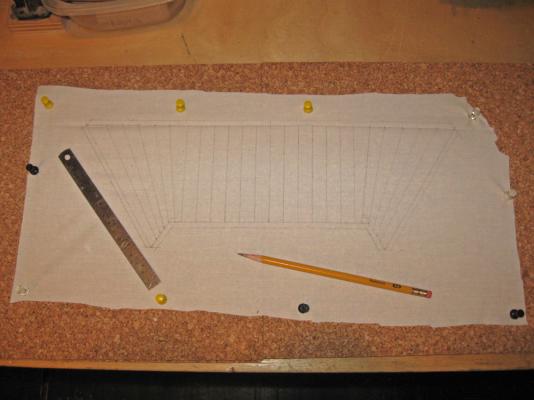
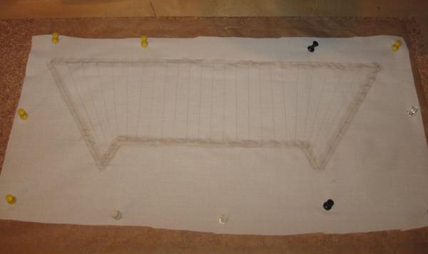
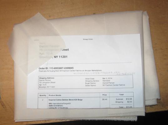
Hello again - Thanks for the likes and comments, and a happy Christmas Eve to everyone. Just a quick post about the last bit of work before I go on vacation for two weeks. Since the last posting the standing rigging has been completed. Here are two shots of the overall model with the upper standing rigging complete. No different techniques were used, just a selection of thinner lines as the rig got higher. The final lines, the fore t'gallant stay and the outer bobstay, are tensioned by lanyards between eyes worked into the ends of the lines. 1 1a Here is a closeup of the foretop before any of the running rigging goes on. You can see that the upper deadeyes are not in a perfect line. I have seen similar irregularities in photographs of later, much later, working merchant sailing ships. I do not think that pirates would have been as careful as the Royal Navy, or even the French navy, at such details, so leaving one a little shorter adds to the realism. 1b The first element of the running rigging was the spritsail, the spar handling lines, a furled sail, and the sail lines. Here is how I approached it. The spar is simple. A properly sized length of square maple stock was planed to an octogon. The center section which remained octagonal was marked off, then the spar was tapered and rounded with a small plane, Dremel sanding drums, then a sheet of sandpaper glued flat to a piece of acrylic. This procedure is exactly like that used to shape the masts in an earlier log entry, just carried forward till the spar was properly tapered. Cleats were mounted in the center section and stop cleats glued and pinned at either end. 3 The first lines to go on were the stirrups and footropes. Since the ship was quite small the spritsail only needed one stirrup on each side. These were made by laying up an eye in the end, then wrapping the running end over the spar twice, leaving enough hanging down so the eye came 3 feet (1" in scale) below the top of the spar. This would allow a sailor to stand on it and reach over to furl the sail. An eye was siezed into the ends of the footropes sized to slip over the spar ends. The free end of the footrope was slid through the eye in the stirrup and a small eye worked into its end. According to Budriot the ends of the footropes were not lashed to the spar or to any of the lines circling the spar, but laced to each other. Once the lengths had been adjusted and set, and the center lashing tied, a series of small weights were used to make the stirrups and footropes hang vertically, as if by gravity. 4 In the closeup you can see the first heavy steel clip pulls the footrope down near its seizing, while the second pulls down the stirrup. The two smaller aluminum clamps were set on either side of the stirrup to mimic the footrope sag. 5 Once I liked the look the lines were painted with water to assist in the penetration of dilute white glue which was left to dry to set the sag permanently. The various blocks and rigging fittings were added to the spar. The first was the line for the sling. An eye was spliced into one end which was wrapped around the spar and under the center cleat on the port side. A round seizing secured it in place. The running end was left free until it was time to lash the spar to the bowsprit. It did, however, provide a way of temporarily securing the spar while various measurements were made. Moving outward, the clew blocks were tied to the spar so they hung down, then the small deadeyes for the standing lift which sit on the forward face of the spar. At the end of the spar a large single block was spliced on facing forward for the running lift, and a similar single block on a short pendant for the brace. Not shown in the photo are a large single block tied to the center of the spar for the halyard, a small block in the center for the leach line, and the clew lines themselves which tie to the spar just ouboard of the clew blocks. 6 Then I turned to the sail itself. The first choice was what to make it out of. Working in 1/36 scale allowed me to use actual cloth rather than silkspan or other paper-based product. I haunted fabric stores and searched the internet for the thinnest that I could find. I found it at the New York Fashion Center. Their Imperial Batiste measured out to 0.008" (0.288" in scale, or just over 1/4") which was acceptably thin. As you can see in the photo, you can read through it. Best of all, it is quite reasonably priced. 7 Now, how to shape it to a furled look. Although most of my ideas on this topic have been developed over many years, they are succinctly stated in an article by Professor John Tilley of Texas A&M which can be found on this website at this location: http://modelshipworldforum.com/resources/Rigging_and_Sails/ScaleSails.pdf The first idea is that a furled sail has to have less bulk than a full one, and that this has to start out as a trapezoid, because the outer ends of the furl are even less bulky than the middle. I modified this to add two triangles of cloth that would hang down as representing the clews of the sail. To this shape a series of panel lines were drawn on. The outer ones were angled to lie parallel with the outer edge of the sail. 8 After that a lot of experimenting went on to get the size, layout and panel lines adjusted. Then the edges of the sail were painted with white glue. When dry the sail was cut out, the tabling folded and ironed, and the sail mounted on the spar. It was soaked in clear acrylic matte finish and teased into furls that were tied with gaskets to the spar. The teasing process continued throughout the drying process. Where I was unhappy, water was liberally painted on the problem section to soften the cloth and the sail adjusted some more. I was so caught up in the process that I failed to take photos of my techniques, but I will do that with the fore and main courses, which will be furled in similar fashion. 9 With the sail mounted to the spar the sling was tied and siezed. The halyad, the standing and running lifts, and the braces were tied, run through the appropriate blocks, and then to their belaying points. Several, including the running lifts and clew lines, go through a long gammon block with six sheaves lashed to both sides of the gammoning. 10 At the belaying points, whether cleat or timberhead, the lines were secured with hitches. not knots or glue, leaving long tails for further adjustments. Pirate Pete is supervising to make sure. 11 So here is where it is as I leave for Santa Fe. I know that there are some items that I will have to adjust when I get back, and please, please, if you spot any that you question, let me know so I can correct them before I go too far past to easily redo. 12 My very best wishes to you all and your families. I will see you in the New Year. Dan


- 241 replies
-
- 20
-
-
- queen annes revenge
- pirate
- (and 2 more)
-
Hi Mark - Really sweet work on the framing. Looks even better enlarged and flipped right side up. Smooth, fair and symmetrical. Not much more you can ask of a set of ribs. Cherry will work well for planking. I have used it many times. However, I have run into some problems occasionally: Some pieces seem to have been over-dried and are brittle. They splinter rather than cutting cleanly. Make sure your blades are sharp. Also, the color can vary substantially under the final finish even when the unfinished pieces look quite similar. If you will be coppering the lower hull consider using a less expensive, more user friendly wood there. Looking forward to seeing your progress. Dan
-
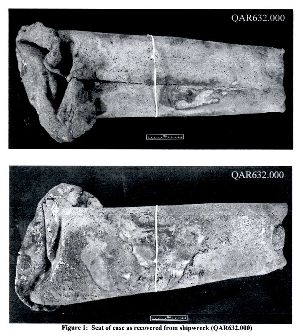
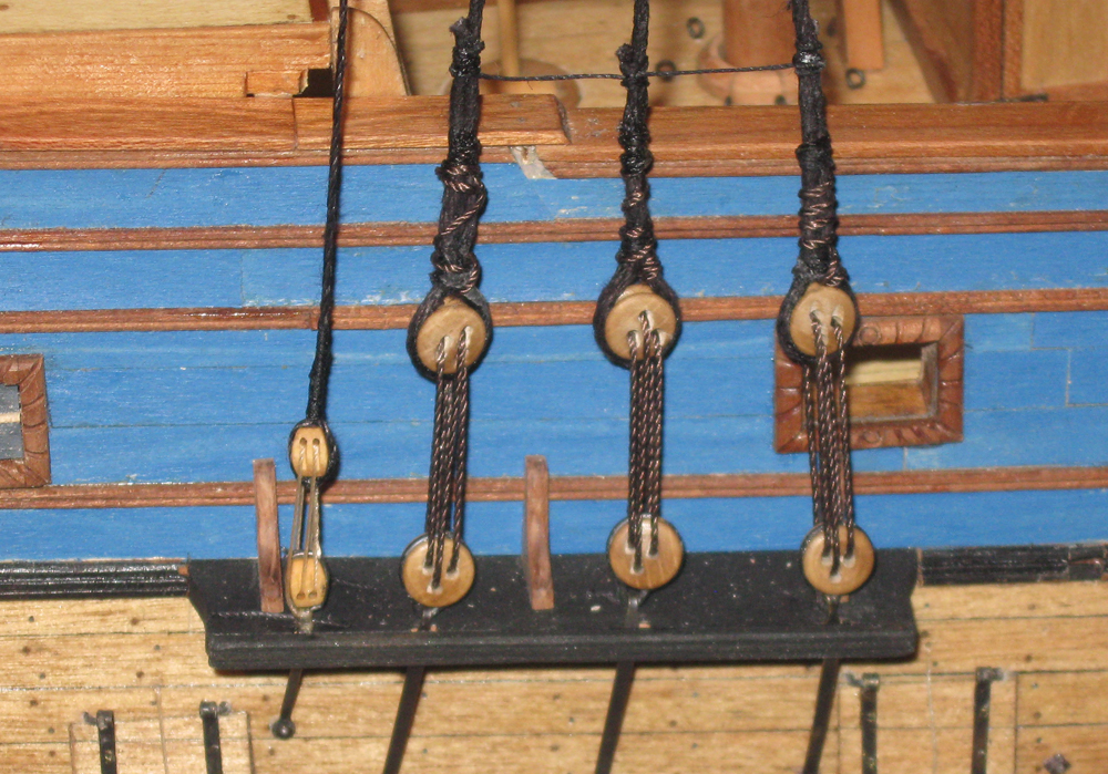
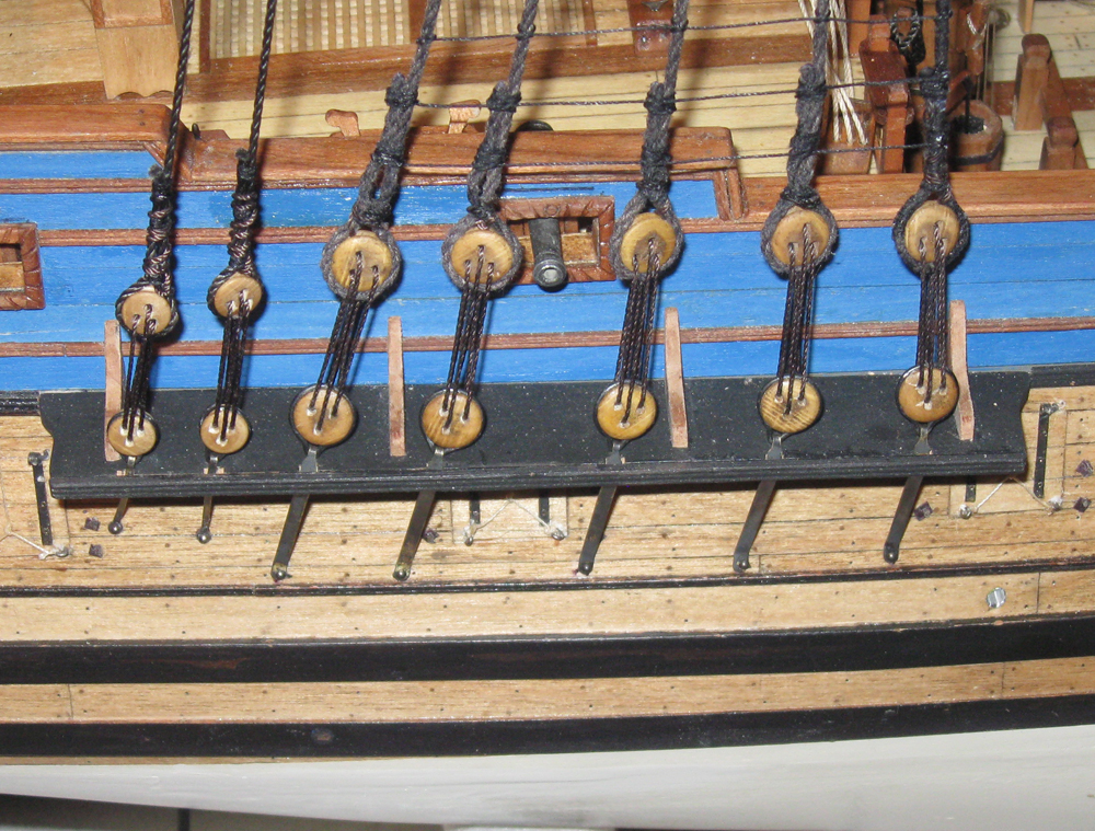
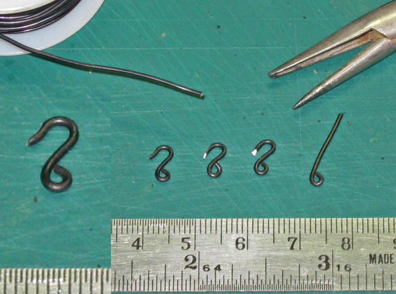
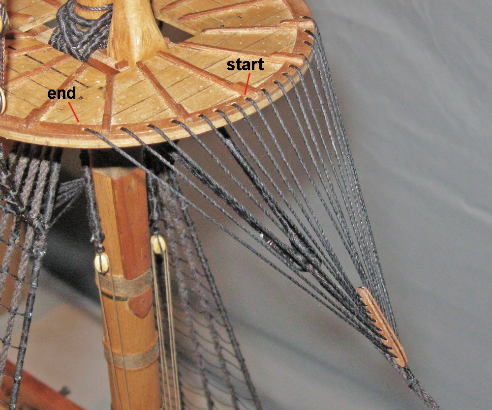
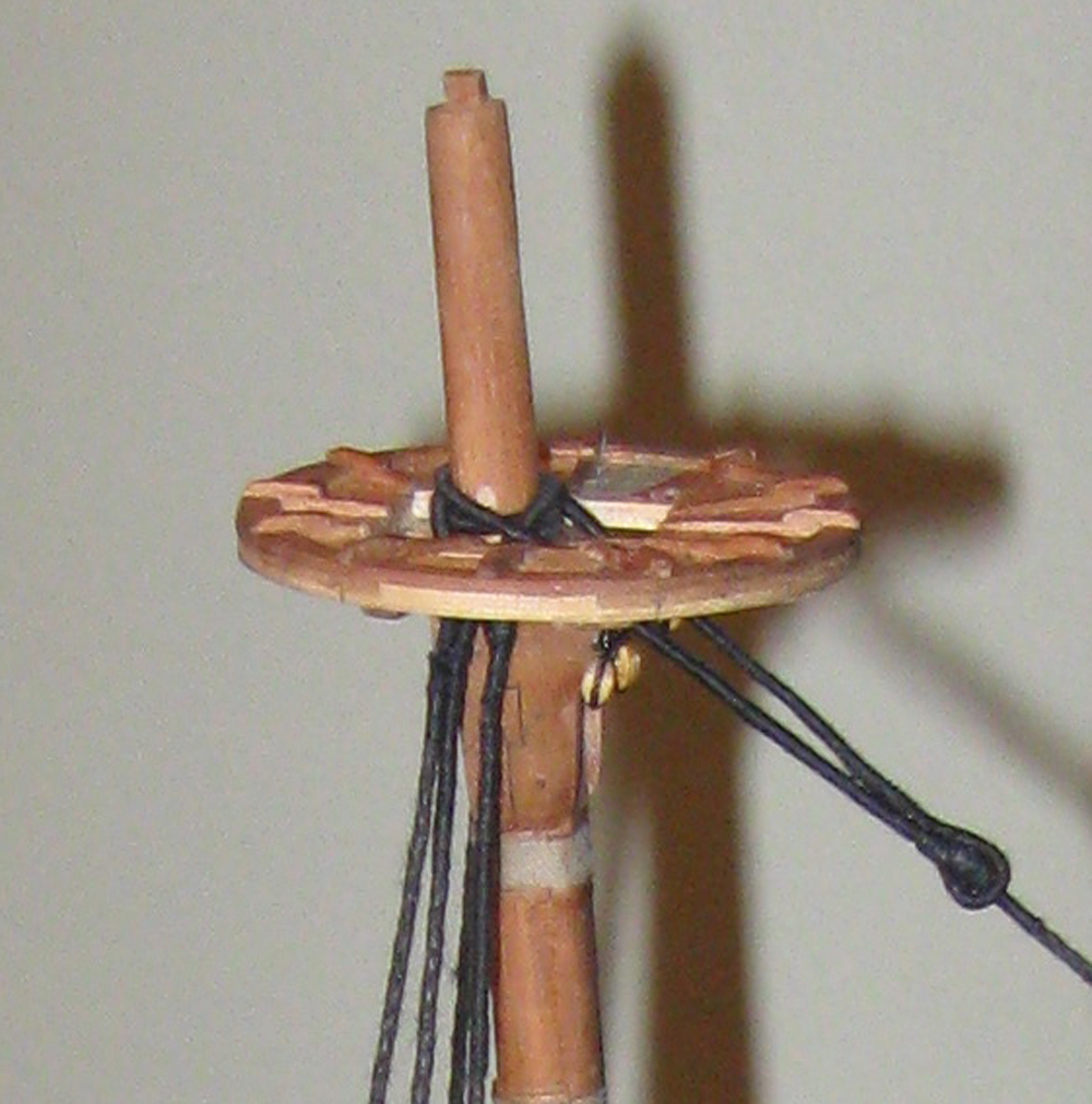
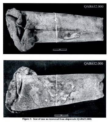
Log 29 – lower standing rigging Two weeks ago there were no masts or rigging set up. The channels weren’t even on. 1 Today, with the invaluable help of JerseyCityFrankie, the lower standing rigging is done and the upper rigging well on its way. 2 Here is how it was done. First came the channels. They are all situated in the line of the second molding, just under the blue painted bulwarks and above the gunports. In typical fashion they are stylishly curved at each end, with a cap strip that captures the deadeye “chains”. They are located such that the foremost deadeye lines up with the center of the mast. In the photo you can see how I miscalculated this and the main channels had to move aft about half an inch, leaving a gap in the molding that had to be filled later. Unlike English practice which usually had the supports under the channel, French practice at the time was for wooden knees above the platform. 3 For the lower masts, the rule of thumb is that deadeyes are half the diameter of the mast, while for upper masts they are more closely the size of the mast. For this 17mm main mast the deadeyes are 9mm boxwood ones purchased from Model Shipways and stained. Each hole was opened a little and a lanyard groove cut for each hole on an angle to ease the bend in the lanyard line. In my restoration work it is almost invariably true that the rigging line fails at these sharp corners in deadeyes and blocks, so wherever possible I will be preparing the rigging fittings this way. The deadeye “chains” are not the three links that are seen on later ships, but solid iron straps that are bolted through the hull at the bottom. At the top there is a loop that hooks through a raised section of the deadeye strop. This setup has been seen in contemporary drawings and confirmed by artifacts discovered in the excavation of La Belle, LaSalle’s ship when he explored Texas in 1674. La Belle is a little early and about half the size of the QAR, but the rigging fittings should be similar so I have decided to go with this. I will be taking many cues from the La Belle excavation as reported by Glenn Greico in his Master’s dissertation, available here: http://nautarch.tamu.edu/Theses/pdf-files/Grieco-MA2003.pdf My deadeye straps were made from brass strip, with a narrow section ground and bent to a hook, then chemically blackened. They are pinned to the hull with half inch roundhead steel nails that are glued into holes that angle upward slightly to counteract what will be some pretty high stresses as the shrouds are tensioned. 4 The metal strops were formed from stiff iron wire. (Yes, there are straps, strips, and strops. Sorry about that, but I’ll try to keep them straight). Here is the jig that I used. It is for the deadeyes in the tops which have long legs to go through the top, but the principle is the same. 5 A length of wire is bent around the middle pin, which is there to keep the loop open for the later hook. The legs pass between the pair of larger pins and are then bent out in a straight line. A deadeye is held hard against the center point and the legs are bent by hand into the groove till they cross at the top. Using the legs as handles the strop is spread apart until the deadeye can be popped out. A bit of epoxy is laid into the strop groove and the deadeye is put back into the strop and rotated as needed to line up properly. The legs of the strop are clipped short and the ends bent down into the groove with pliers. When the epoxy dries they are ready for use. Although the gap in the strop used to worry me, I have never had one open up. Besides, if the stresses are that great, I would rather that the strop open up than have the entire channel pulled up. With the deadeyes all strapped and stropped to the channels the rigging could begin. I did this from aft to forward, with one exception. The very first piece of rigging was the gammoning around the bowsprit. This is important because all of the stresses and tensions of the standing rigging are anchored here. You can see the way the lines cross as they wrap from aft to forward on top of the bowsprit, but from forward to aft within the gammon hole in the stem. The gammoning is finished with a few round turns just above the grating in the head. 6 You can also see in the photo that the seat of ease has been lined with lead like the scuppers. I would not otherwise show this feature, but the excavation of the QAR has turned one up, so it has been added. 7 Beginning with the mizzen mast the deadeyes were turned into the shrouds and given three seizings. The shrouds were made from linen line sourced from a pool cue manufacturer who uses the line to make non-slip grips. The line comes in unbleached white, which was dyed with RIT liquid black dye according to the package instructions. 8 As was consistent for almost all ships of this period, whatever their origin, the deadeyes were laced with oiled line. The lacing had to be protected from salt water, but could not be tarred since it must have been adjusted fairly often as the shrouds stretched from the strains of sailing and weather. This has been represented with a dark brown line rather than the darker black of the tarred shrouds. 9 At the mizzen top the shrouds are served as they go over the trestletrees and around the masthead. Under the top are several blocks for the running rigging and for the crojack yard halyard. The mizzen stay is served and an eye worked into the end. A mouse is raised on the stay to form the loop that drops over the masthead and the heads of the shrouds. The mouse is shaped with the bulbous end down, in the French fashion, so the bulb jams against the eye. English practice is to have the tapered “tail” of the mouse slide through the eye until it has no more space to run. I don’t know why there is this difference, or whether one or the other conveys any kind of advantage. 10 At the lower end I ran into a problem. Although never detailed, it is clear that the mizzen stay has to set up to a collar on the main mast. However, if the stay is centered it interferes with the ramshead block and tie for the main spar. I decided to offset the collar to starboard with a bullseye seized into it. A set of double blocks were seized into the lower end of the stay and the upper end of the collar, then joined with a lanyard. The lower end of the collar is belayed to one of the large mast cleats. 11 The shrouds for the main mast are set up much like those of the mizzen. There are five heavy shrouds with large deadeyes, and two more on the aft end of the channel for the topmast shrouds. 12 For the main shrouds the forward one is served its whole length to protect it from chafing by the mainyard sail. The other shrouds are served only where they go around the masthead and then for a short distance below the top where they are seized to each other in pairs. The three futtock shrouds have been hooked into the strops of the upper deadeyes then turned around a futtock stave that is seized across the shrouds. You can also see the pendants that hang below the top, which are served all over with an eye worked into the end. They were used as anchor points for hauling up the ship’s boat, supplies, etc. 12a Here in a later photo they are shown with a double block hooked into the eye, the running line goes down to a corresponding block at the deck which is hooked into an eyebolt near the base of the mast. 13 These hooks were made up in my usual way, by turning an eye into appropriately sized iron wire using orthodontic wire bending pliers. The wire is then turned back over the pliers and clipped off. For the larger hooks used for the pendants the clipped end was further tapered with a grinding drum, then the tip was recurved as in full sized practice. 14 Aft of the mast a set of catharpins are laced to the futtock staves and pull them inward against the strain of the futtock shrouds. According to R.C. Andersen this diagonal pattern was used by the French, probably to leave space immediately behind the mast for the main yard ties and other rigging lines. They were installed on all three masts as they were rigged. 15 The main stay is set up with an eye and mouse, just as the mizzen stay was. Although this is the largest of the rigging lines on the ship I decided not to worm it, nor to have a preventer stay. I reasoned that a small ship that had been a slaver for several years and was now in the hands of pirates would not have the spare manpower to maintain lines that would not be called on except in battle, which the pirates avoided at all costs. The collar is set up in the French fashion, served all over and anchored around the base of the bowsprit. The two legs are seized together at the bow and then on both sides of the foremast. Large triple blocks are seized into the ends of the stay and collar and laced together. 16 In this close-up you can see the blocks, which the French used rather than hearts favored by the English. You can also see the thumb cleats that secure the collar to the mast on either side. 17 The standing rigging to the foremast is identical to that of the main mast, except that the stay goes to a collar on the bowsprit. You can see most of what has been discussed in this one photo. 18 The fore and main masts had crowsfeet laced from the top to the stay to prevent the lower edge of the topsails from curling under the top and fouling all the lines and blocks that live there. These were made by first shaping the euphroes out of pear. They are about ¾” long, with a strop groove cut in all around the edges. Since there are 16 holes in the forward edges of the tops, the euphroe has 8 corresponding holes. A strop was seized into the groove with the tails left on which were used to attach the euphroe to the stay. 19 The crowsfoot was formed by lacing the line up through the hole in the top closest to the center cleat on the starboard side. A stopper knot under the top prevented it from pulling through, much like the deadeye lanyards. The line laced down and through the top hole in the euphroe, up and over the lip of the top on the port side, down through the first port side hole, and up the second port side hole. It continued down and through the second euphroe hole, up over and down the second starboard hole, and up the third starboard hole. The lacing continued loosely back and forth in this manner until the line reached the outermost starboard hole. All the lines were tightened and a knot was worked close under the top and the excess line snipped off. To strengthen it all the lines were painted with dilute PVA glue. 20 The final element for the lower standing rigging is the ratlines. The line itself was selected to scale out to ¾” diameter, suitable for the weight of a man, and spaced 10mm apart, which converts to 15” in real space. As for tying them, many others have gone over the lacing of ratlines, so I will not repeat that here. Suffice to say that they are attached to the outermost shrouds of each gang with an overhand loop, which makes the smallest bulge around the shroud, and secured to the inner shrouds with clove hitches. This is not nearly as daunting as it may seem. Once a rhythm is established it goes rather quickly, like knitting. Frank and I tied all the ratlines for all the lower shrouds in just four hours. No special effort was made to have the ratlines sag between the shrouds, but they naturally take on a mild curve as the tying proceeds. This can be increased or reduced by gently tugging on the appropriate knots until the desired look is achieved. Once I was happy with the overall look the entire shroud gang was painted with dilute glue and, when the glue was dry, the tails were clipped as close to the shrouds as could be managed. 21 I hope to have another report out before Christmas, with the completion of the standing rigging and the beginning of hanging the spars and sails. If not, a very Happy Holiday Season to all and I will be back in the New Year. Dan


- 241 replies
-
- 16
-
-
- queen annes revenge
- pirate
- (and 2 more)
-
Michael - Let me be the first to say how impressed I am - again. Dan
-
Hi Mark - Good looking progress. Your plan for the next step sounds right and should give you a stern that is accurate, true, and strong. I do wonder about the shape of the doorway to the quarter gallery. In your drawing it looks much too angled, although this might be an artifact of the angles of the plan. As a doorway it should be pretty much a rectangle with sides that are perpendicular to the waterline so they will be vertical when the ship is at rest. Of course, this is a very small nit and probably will not be visible in the completed model. Looking forward to seeing your continued excellent progress. Dan
-
Seriously terrific work, Michael - I see you found Andre the Giant to help you out. That can't possibly be your fingertip in the photo. If it is, I tip my cap to a true master. Be well Dan
-
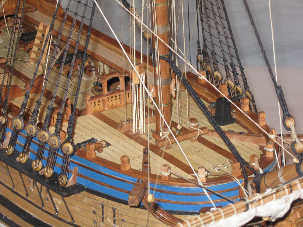
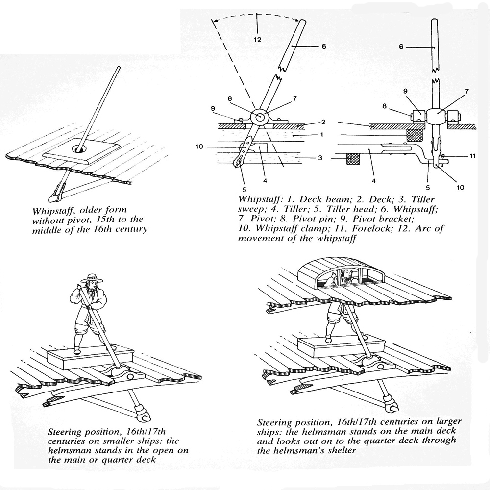
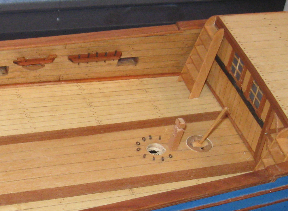
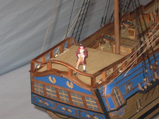
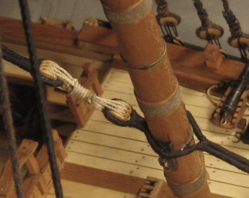
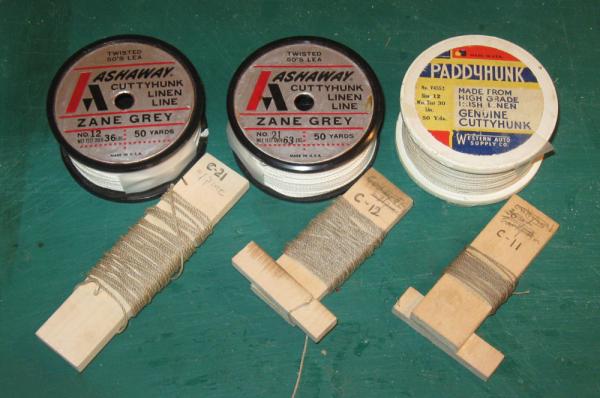
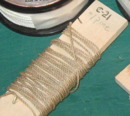
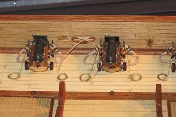
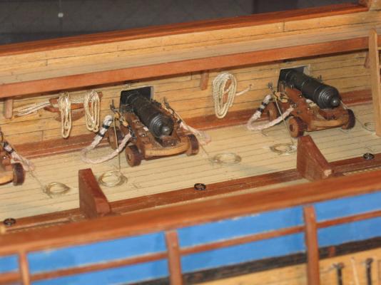
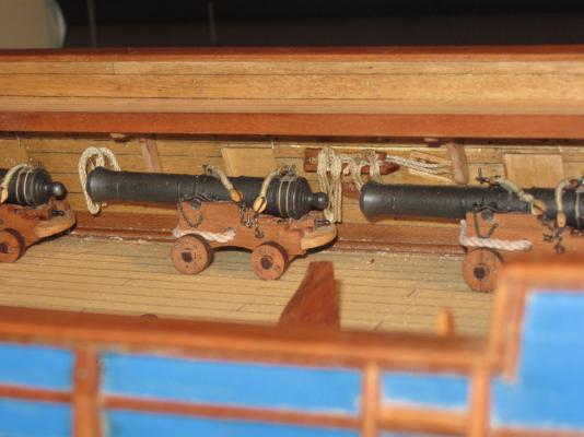
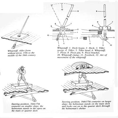
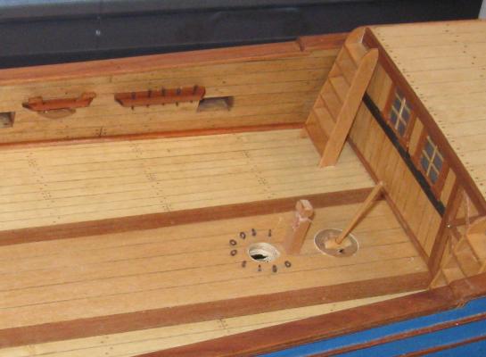
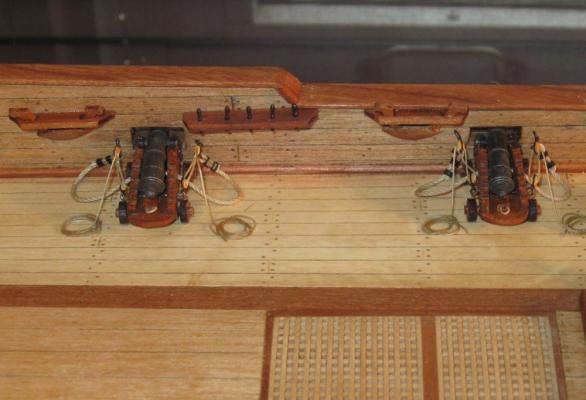
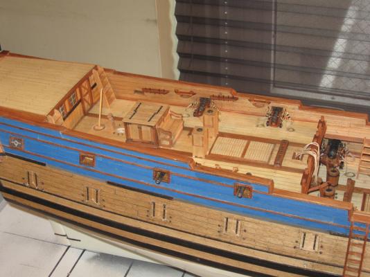
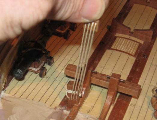
Hi again, and thanks for the likes and compliments. It is going well, I think. I am trying to create the look of a working ship, rather than one fresh off the building ways. Now that the foredeck is installed, I turned to the waist. With the cannon rigged out they can be covered by the gangways. But first I decided to put in the ropes that go through the hull and belay below the gangways. It would have been much harder to do them with the gangways in place. These are the main course tack that goes through the chesstree, and the two sheets that go through the sheaves in the hull. These lines will be some of the larger running rigging ropes and, because of their locations, some of the more visually prominent ones. They have to be good quality and look like miniature rope. I could have laid them up on my ropewalk, but I have a few spools of treasured Cuttyhunk Irish linen line (which is no longer available for any price). The Zane Grey and Natural colors are too white, but a quick run through Minwax wood stain in Ipswitch Pine color makes them look the right shade. 1 Even examined closely this gives them the look of miniature rope. 2 I fed the line through the hull openings. The larger line (C-21) was used for the tacks which belayed to cleats, while the smaller one (C-12) was for the sheets.which belayed to the staghorn kevil. 3 Although each line is tied off properly, they were all further secured with dilute white glue. When dry the ends were nipped off and hidden by separate rope coils. I make these on a simple jig. A block of soft wood - basswood in this case, but it could be balsa - has several holes drilled in the top face and one or two holes in the front face in the same line. Removable brass pegs fit into the holes and everything is given several coats of clear finish to keep glue from sticking to it. Then matching lines are wrapped around the pegs with the ends friction fit into notches in the jig. 4 As I wrap I randomly make larger and smaller loops and even the occasional figure eight. When I have the look that I want, the coils are painted with dilute white glue. Actually, they are first wet down with water, which helps the dilute glue to penetrate the line rather than having it sit on the surface. When the glue is dry the top peg is removed and the coil peeled up from the jig and trimmed. Using dilute glue means that the coils are flexible while still holding their shape. 5 The coils are hung over the belaying points, teased into position where they look like they are hanging with the force of gravity, and secured with white glue. 6 7 In the photos you can see the supporting knees for the gangways. These were made as before by cutting and shaping a stick and then parting off individual ones. After locating and installing the forward and aft ones, the gangways were glued in, then the middle two knees for each gangway were installed. In the photo you can see the ropes that feed through the hull. I left what I hope is more than enough to reach to the sails, but we will see when the rigging is installed. 8 The final fittings in the waist were the four ladders from the gun deck up to the gangways. They were wider at the base than at the top, and were built up as has been detailed before as a stack, then parted off. 9 After individual ladders were parted off they were cleaned up, stained and installed. 10 Now that the waist was complete, I turned to the quarterdeck. The railing that was built up last time was installed, then the whipstaff. For those not familiar, this is an obsolete steering device that predated the wheel. It consisted of a rotating fitting called a rowel set into the deck through which a staff passed before it hooked into the end of the tiller arm. Moving the staff port or starboard turned the rudder. It was not very efficient, but then most steering was done with the sails during this time. 10a A hole was drilled in the deck and a piece of pear cut and sanded to fit. The fore/aft slot for the rowel was carved into the pear piece, as were indentations for the staff clearance athwartships. The rowel was turned from maple, and the hole drilled to allow the staff to have a sliding fit. I set the staff at an offset angle and glued it in place. 11 You can also see the ladders from the quarterdeck to the poop deck on the roof of the captain's cabin. These were made up as before, just a little taller than the gangway ladders. Similarly, the post with sheaves for the lateen halyard was made like the fore and mainyard halyard fittings. Along the bulwarks are staghorns and pinrails as drawn by Budriot. I am not completely sold on the pinrails, which do not appear anywhere else on the ship, but they are certainly needed for belaying points. The four 4-pounder cannon were rigged and installed like the 6-pounders on the gun deck. 12 Now the deck fittings that were made up almost a year ago could be installed. These were the companionway house, the officers' bench in front of it, and the two small binnacles. 13 The ship is now ready for rigging, which will start next month. 14 Until then, happy Thanksgiving to all and to your families. Dan


- 241 replies
-
- 23
-
-
-
- queen annes revenge
- pirate
- (and 2 more)
-
Really nicely done, Bob. Add my congratulations to all the others. What sort of case are you planning to display your success in? Dan
-
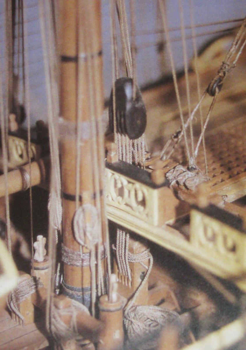
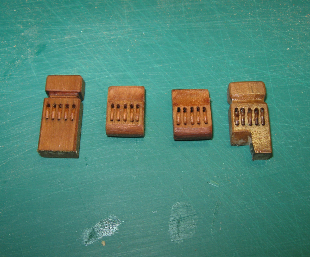
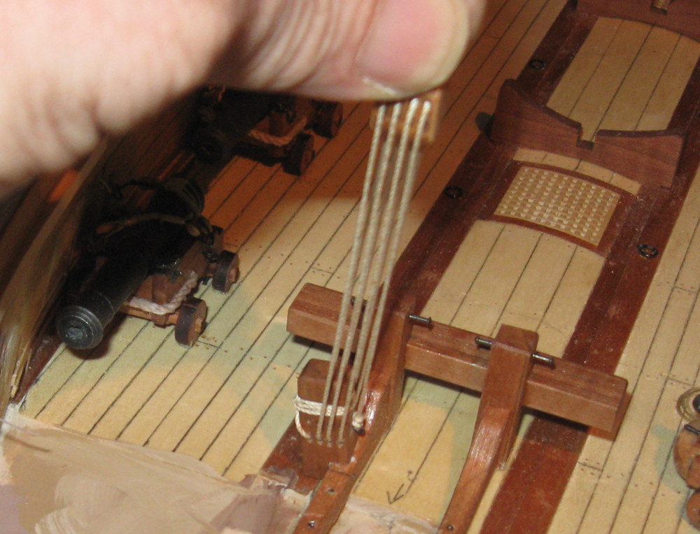
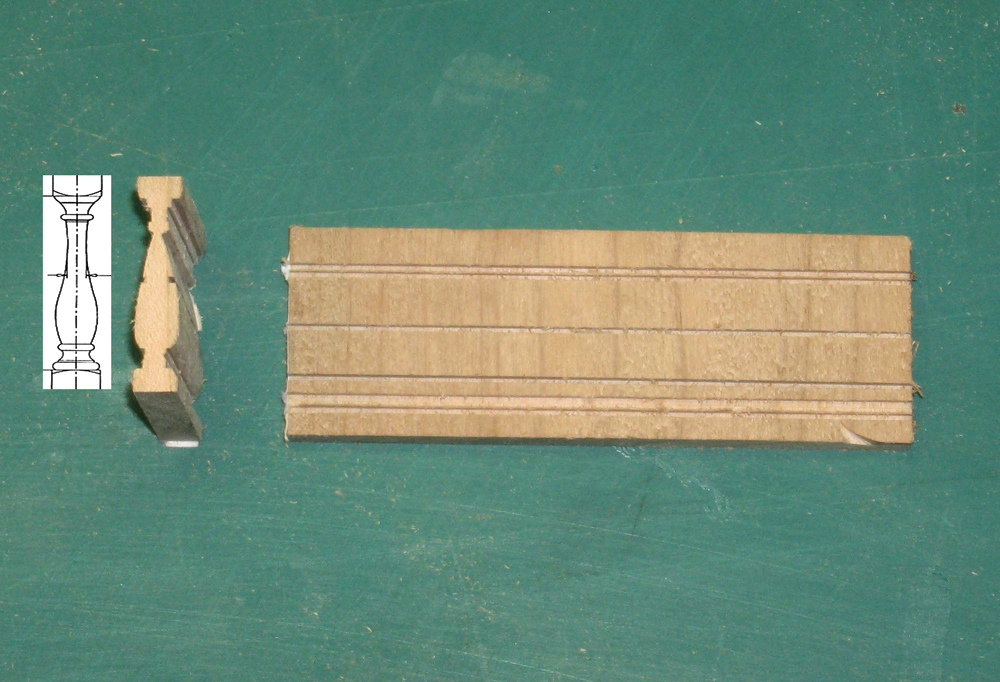
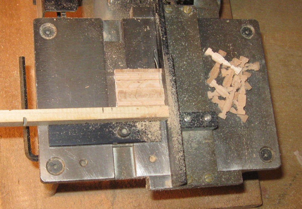
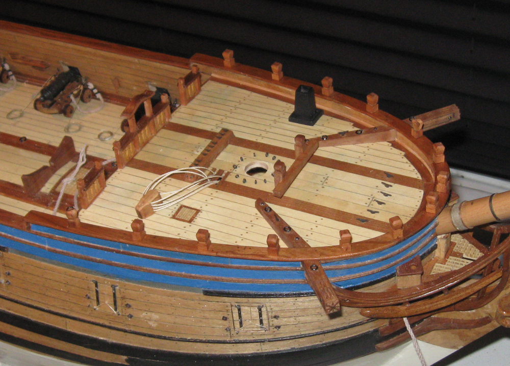
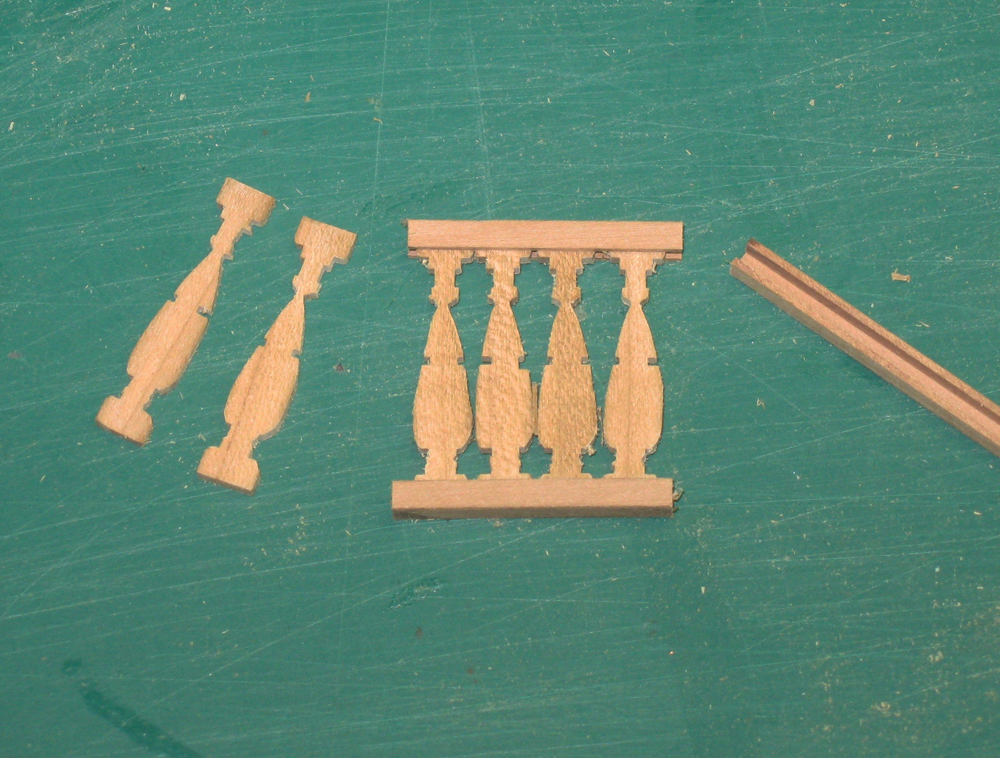
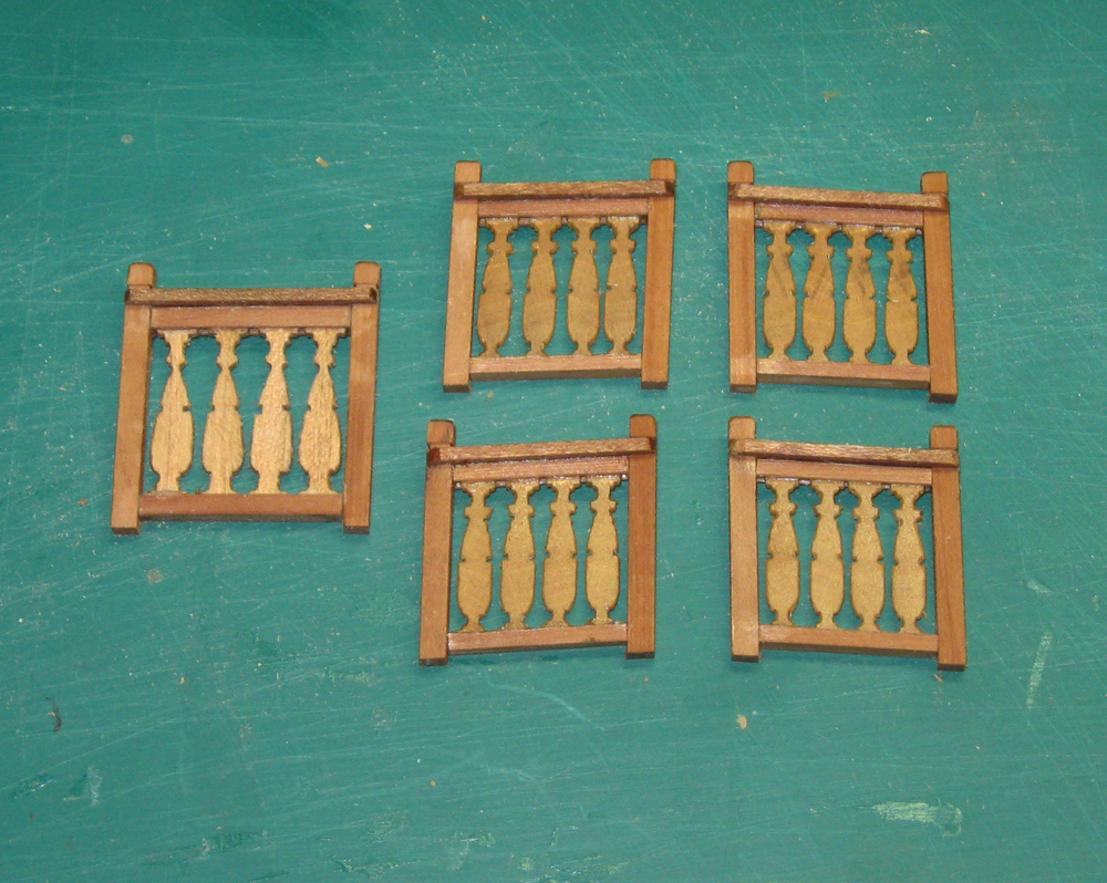
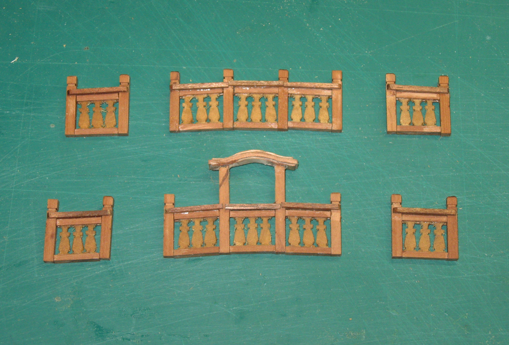
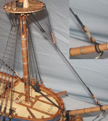
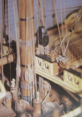
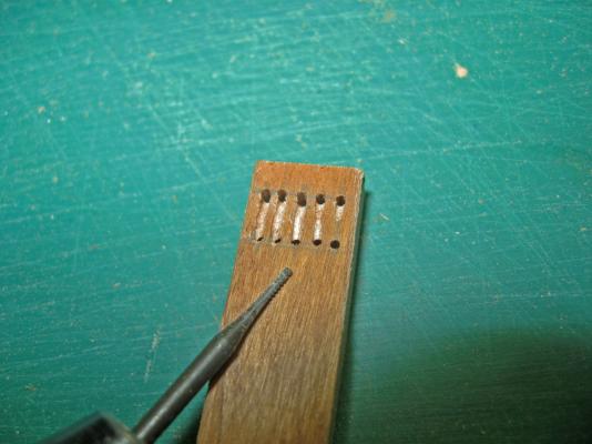
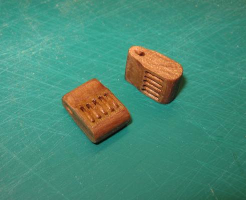
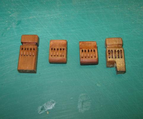
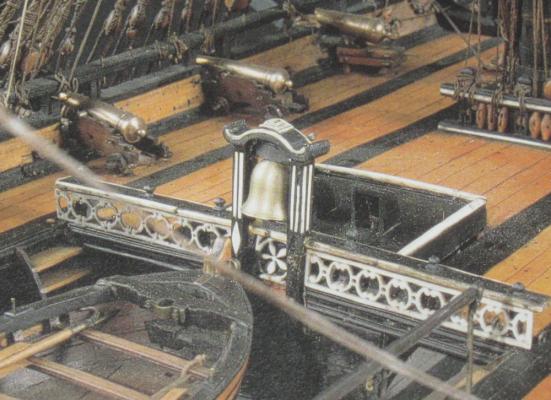
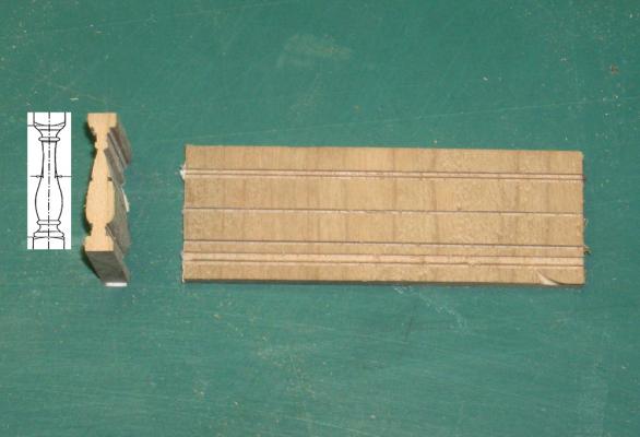
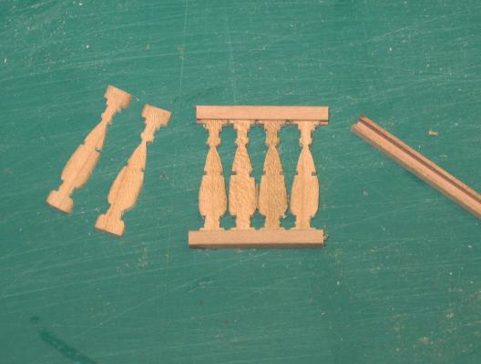
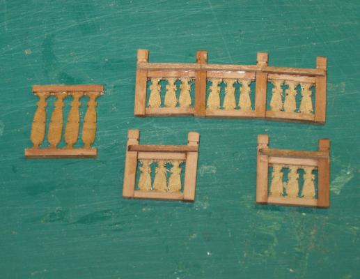
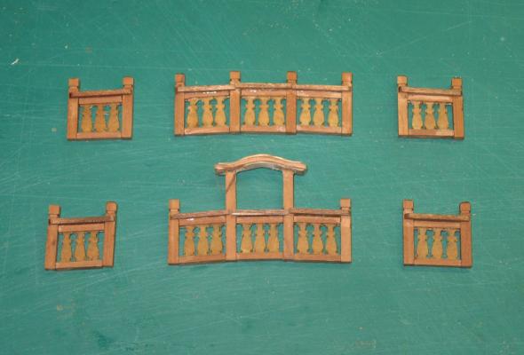
Hello again and, as always, thanks for the likes and comments. This time I turn to the details of the foredeck. Although the basic structure and planking has been completed for a while, it was never attached to the hull because various components under the deck had to be completed first. These included the guns that were done last time, the anchor bitts, and the post with sheaves for the foreyard halyard and tie system. Here is the system on a contemporary model. This is the one for the main yard, but the pieces are the same: a post attached to the deck with a number of sheaves for the halyard line; an upper ramshead block with matching sheaves and a transverse hole for the tie which comes down from the masthead; and the halyard line running between the two. As you can see, the line goes through the deck and must pass through a series of holes or a scuttle of some sort. There are no clear photos of this detail that I could find. 1 I also had to figure out how to install them fully rigged, since it would be quite difficult to get to the posts once the upper decks were in place. Even RC Anderson recommends fully rigging them, then tensioning the system with the tie and not the halyard. Here is what I came up with. I started with the ramshead blocks. I made these up with false sheaves rather than trying to build them up since they would be rigged and the sheaves hidden under the running line. A series of five holes was drilled in a sized piece of hardwood in two matching horizontal lines using a Dremel drill press. Then a thin grinding bitt was laid against the wood to cut a channel from one hole to the other. You can see where I am starting the process in the right side hole with the others in later stages of carving. 2 These channels were carefully deepened and straightened, then angled at the ends of the cut until they approximately replicated the curve of the sheave that is not there. This was done on both sides of the workpiece. Now the blocks will accept the line which will look as though it is running around a circular sheave. Once all the slots were cut and cleaned up, the block was parted off to length and taken down to the ramshead shape with a sanding drum. Here are the two for this model. I do see that the tops of the blocks need some further shaping to match the one in the earlier photo. 3 In a similar way the posts that will go under the foredeck and quarterdeck were cut, pierced, and shaped. The one on the right is an early example, before my technique was perfected, and which would be replaced if it were not going to be hidden under the foredeck. The cut at its base is so it can fit over the knee of the anchor bitts, which brings it to the starboard side of the centerline. 4 And here are both sets, which were made up at the same time to maximize consistency. You can see how the posts will be secured with brass rods into the deck for strength. 5 Here is the foreyard set fully rigged. Sharp eyes will notice that there are only 4 loops of the halyard line and not 5. When I went to install the set initially it really seemed too large for the ship. I went back to my photos of contemporary models and found that the 5-sheave blocks were used on the largest three-deck warships. This small frigate would not have needed such lifting power, so I took the finished pieces to the table saw and sliced off one side of all the pieces to eliminate one sheave. This had the happy result that the scuttles in the decks did not have to be quite as large. More on this later. 6 The next detail for the foredeck was the railing to keep sailors from falling into the waist and to house the ship’s bell. I wanted to build and install it now so I could secure it from beneath the deck with metal pins before the foredeck was put on the model. Here is a photo of a fairly fancy one from a model of a French ship of a somewhat later period. Although this one is continuous from port to starboard, Budriot shows two gaps which will be used later to house spare spars and topmasts, so there is a long central section with two short sections flanking it. 7 I decided that my railing would have balusters set in channels for the body of the railing, with posts that went up through a caprail and ended in shaped timberheads that could be used to secure rigging lines. The first task was to make a fairly large number of identical balusters without spending days turning them on a miniature lathe, which I don’t have. I opted for the mill-and-part-off method that has worked for me with support knees, shingles, and other repetitive parts. On the left is the baluster shape that I selected from internet images, then the cross section of the workpiece after milling channels with the Preac table saw and rounding off as needed with a carving bitt. On the right is the side view of the workpiece with the parallel channels cut by the saw. Note that the grain runs vertically. 8 Here the individual balusters are being parted off the workpiece on the Preac. It is set up with the tall vertical fence and the thinnest, finest blade that I have. The workpiece is being fed into the blade and is supported by a sacrificial stick held against the miter gauge. This support stick is taller than the blade height so the end remains attached and I can push the workpiece through repeatedly, taking off identical slices. 9 Here are four of the balusters set into upper and lower channels ready for the end posts and caprail. 10 And here are a set of completed railing sections ready for installation. Note that four of them are angled slightly to match the round-up of the deck. 11 However, when I went to install them I realized that I had made a major mistake. I made the railing about 40 inches tall in scale, enough to keep a man from falling over it into the waist. This looked terrible against the size of other fittings. I went and rechecked my dimensions to find that the railing is really only 18-24 inches tall. Proof, once again, that if it doesn’t look right, it is probably wrong. Instead, a new workpiece was shaped and short balusters were parted off. Here you can see the relative heights of the old and new railings. 12 You can also see that the new workpiece did not cut as cleanly as the old one. I gave them a few coats of finish and, when dry, took off the wood fuzz with a thin pointed grinding bitt. Here is the final set of railings, the upper ones for the quarterdeck and the lower ones with the belfry for the foredeck. 13 So here is the foredeck ready for installation on the model. You can see not only the railing and the scuttle for the halyard, but some additional features whose construction is pretty straightforward: the smokestack for the galley stove, a small grating for the galley, a set of riding bitts with sheaves (also quite low to the deck), the mast coat, eyebolts for hooked rigging blocks, and that curious rigging fitting with ten cleats set onto the deck. 14 And here it is, installed. Newly added are the catheads for the anchors, which are secured to the deck with headed bolts and the timberheads around the low bulwarks, secured with metal pins. You can also see how the ramshead block was led up through the scuttle. It was a tight squeeze but it made it, and then the scuttle was mostly closed off with wood battens to help keep the lower deck dry. 16 Next time, the gangways and quarterdeck, including the whipstaff. Be well Dan


- 241 replies
-
- 13
-
-
- queen annes revenge
- pirate
- (and 2 more)
-
Hi - Thanks for the likes and comments. Mark - you are probably right about the intermittent use of the inhaul tackles. I imagine that during an engagement they would be available but unhooked from the carriage. If the recoil was not enough to bring the gun back far enough to be loaded they would be quickly hooked on, hauled in, then unhooked when the gun was run out. I don't think that you would want them hooked when the gun was fired, as they would get in the way of the recoil. Matt - the pump handles are out of the way to the stern of the gun. Look at the location of the inhaul ring on the deck near the pump. Guns in the midship battery would rarely be slewed very far forward. It was easier to turn the entire ship than to muscle the gun carriages around with handspikes. That said, there are some really tight quarters for the pump bodies, the main mast, and the inhaul tackle, if I am correct that it would be hooked to the opposite ring. Dan
- 241 replies
-
- 1
-
-
- queen annes revenge
- pirate
- (and 2 more)