Ab Hoving
-
Posts
689 -
Joined
-
Last visited
Content Type
Profiles
Forums
Gallery
Events
Everything posted by Ab Hoving
-
 Hello Tony and Tony... Funny how a thread from a year ago suddenly appears to be alive.:-) The question about the right kind of filler is a very good one. It does make a difference which type is used. That is because some kinds are quick drying, but only at the surface and they shrink when at last the lower layers have dried too. I am afraid you have to test some brands yourself, because I wonder if the type I use is available in your country too. The stuff I like most, because it does not shrink, even if a layer of 2 mm is applied is: Houtplamuur (wood filler) Universal by Alabastine. It does not dry as quick as for instance the fillers that are used in car repair, does not smell at all and can be sanded after an hour, provided you did not smear too much and too thick. Use thin layers of filler and allow to dry as long as you can. You can get information at: info@alabastine.nl Hope this helps. Ab
- 65 replies
-
- 7
-

-
- fish hooker
- fishing
- (and 2 more)
-
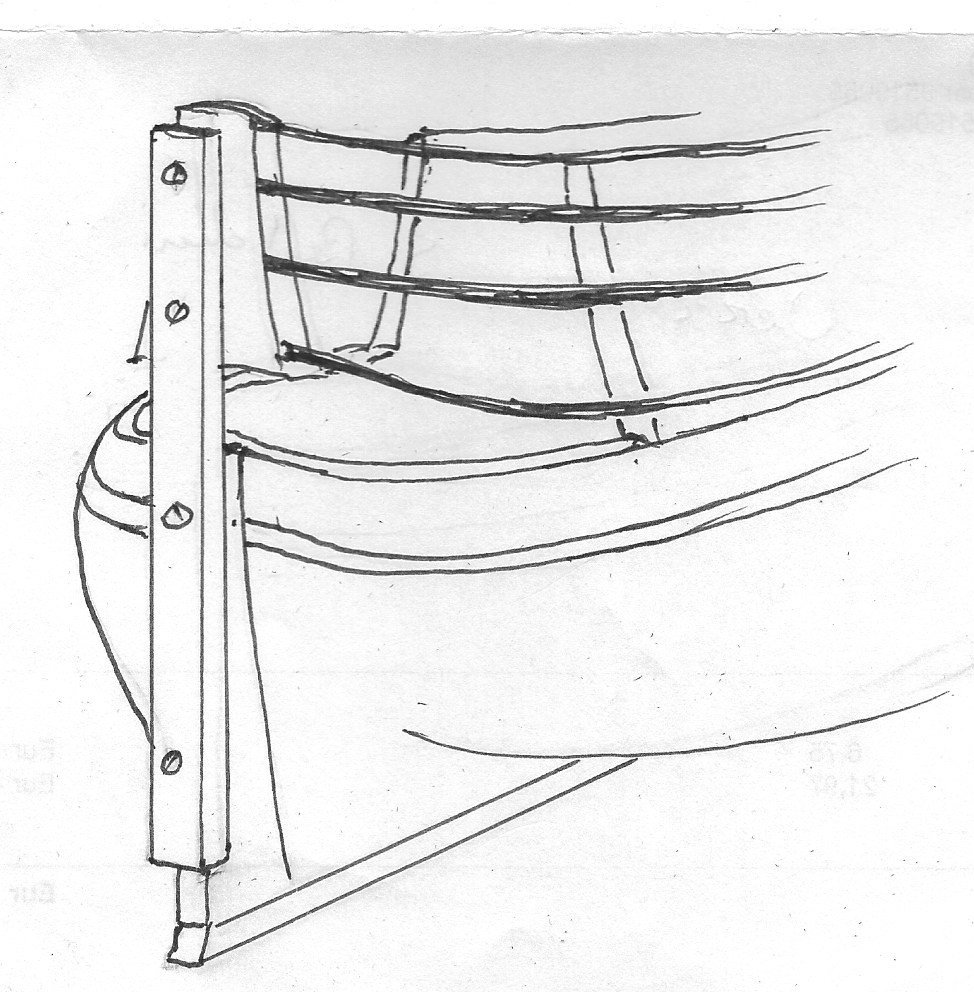
OK Marcus, here you go... Remember that lousy sketch I drew you? Grab that batten you screwed to the sternpost and place it where you had it. Now you have the right position for the taffrail. Make it from card first to get a good fit and then glue your wooden version between the ship's sides, tight to the front side of the batten. Now you can remove the batten and the excess of the planks sticking out backwards. Then show me a picture again. Best of luck, man.
- 332 replies
-
- 10
-
-
- fluit
- abel tasman
- (and 1 more)
-
Need CAD type program
Ab Hoving replied to Sambini's topic in CAD and 3D Modelling/Drafting Plans with Software
He sends you his best wishes and if there are any questions...shoot. -
Show me a view from behind. We should be able to solve this.
- 332 replies
-
- 3
-
-
- fluit
- abel tasman
- (and 1 more)
-
Need CAD type program
Ab Hoving replied to Sambini's topic in CAD and 3D Modelling/Drafting Plans with Software
It is really a pleasure seeing that Rene's lessons did lead to beautiful results. Well done! -
You are really capable of creating a tremendous mess, Marcus.:-) Can't wait to see the rest... Ab
- 332 replies
-
- 8
-
-
- fluit
- abel tasman
- (and 1 more)
-
Just because you asked, Bob: Shellac seems to be a product we forgot. That's a pity because it is a most versatile means of protection for many materials. I once read somewhere that the characteristic 'helmets' of the English Bobbies were made of velt soaked in shellac. Don't know if it is true. My experience with it as a varnish is that it works fantastically on wood. Many late 18th and 19th century models in my depot were done with it and only in cases the models were exposed to a lot of water, for instance as a result of a leaking roof, the material flaked and showed up white. Mostly because the wood underneath worked. It was also easy to replace. Alcohol removed the old remains almost immediately. Bringing on new layers was another story. All remnants had to be removed completely or they would show up very nastily after drying. That indicated that it was hardly possible to touch up an existing layer with some damage. If it had to be repaired, all had to come off. Bringing on the first layer was never a problem. But a second layer could end up in a disaster if the first one was too thick and a third layer almost always was a no go, unless you worked very quickly and never touched areas for a second time with your brush, otherwise you most probably ended up with a nasty slippery looking result. It could be sprayed though, but the result was (in case you did not have a spraying box with air suction) that in a matter of seconds you were standing in a thick fog of dried floating particles of shellac. For french polishing it was great too, though very time consuming. I have used it occasionally for securing knots, but always from a container that was deliberately left open for a couple of days. The material became more condensed and spreading through the textile was limited much more than when using the freshly diluted stuff. To be honest, I don't use it any more after I retired, although I do have a few bottles of it standing on the shelf and sometimes I look at them with a vague feeling of home-sickness. I use anything I can lay my hands on, even CA, to force my materials to behave the way I want them to and I don't care much about the longevity of my products. We are not here to stay forever and the same is true for my models. I'm only interested in their looks, not in their age :-).
-
You Eastern European guys are so extremely neat in your work, which almost makes me jealous. You are years ahead of here in Western Europe.
-
This is probably a copy of an older image. The spritmast dissappeared after 1750.
- 332 replies
-
- 1
-
-
- fluit
- abel tasman
- (and 1 more)
-
Hello Eberhardt, Mr. Schmidt seems to have a great idea for sails during a windless moment. To capture such moments in hanging sails is one of the most difficult things to achieve. I wonder if it works for billowing sails as well. Anyway, I wil reactivate my contacts with my former collegues, hoping they can help me testing this new idea. Thanks for your reaction and also to all the people who 'liked' my contribution. I suppose we can safely close this thread now. Ab
-
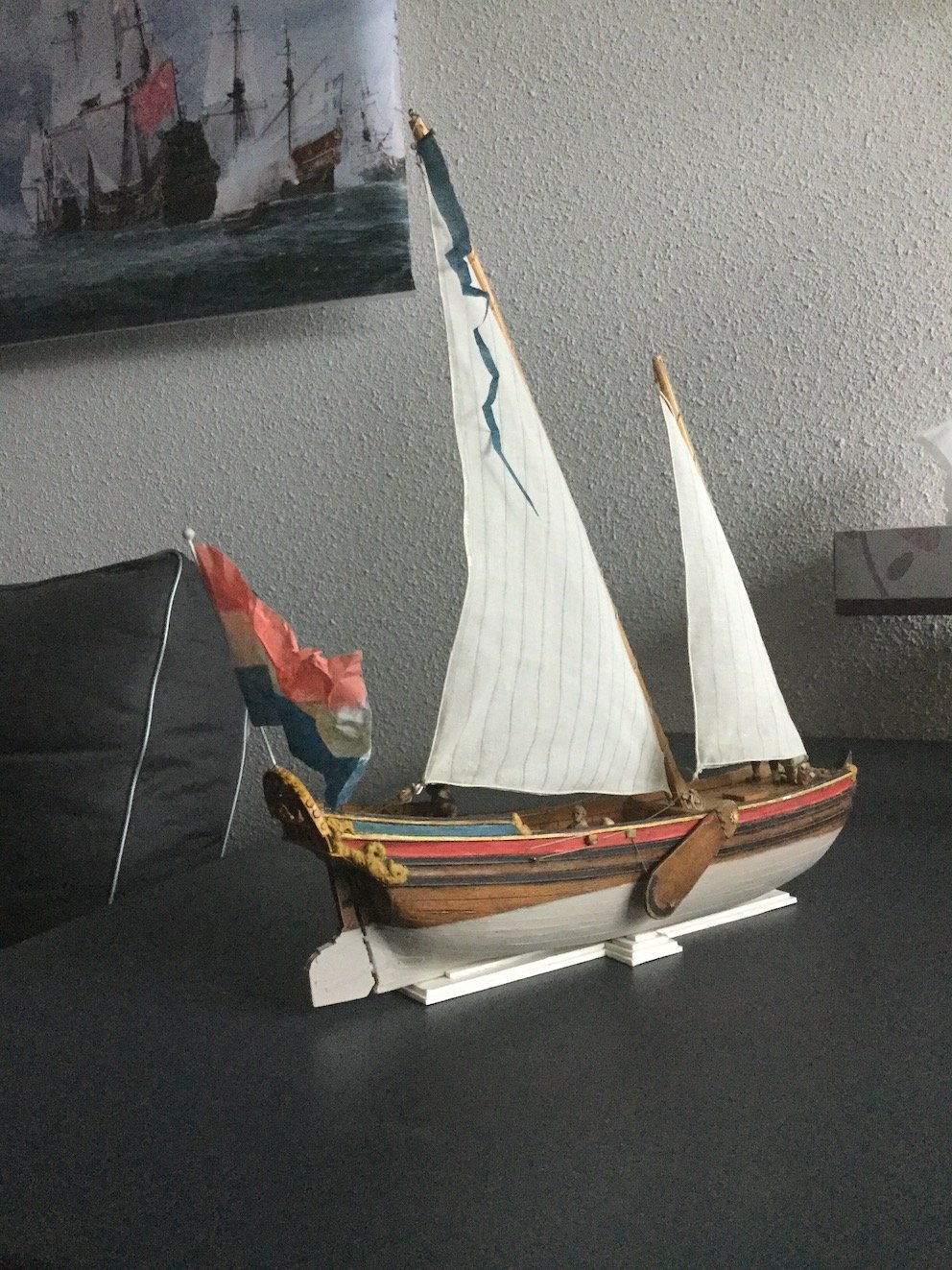
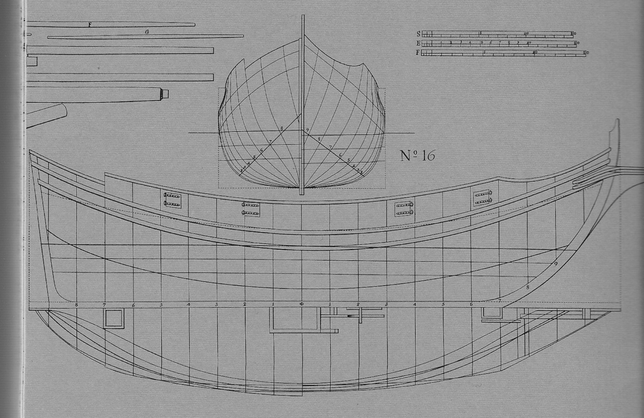
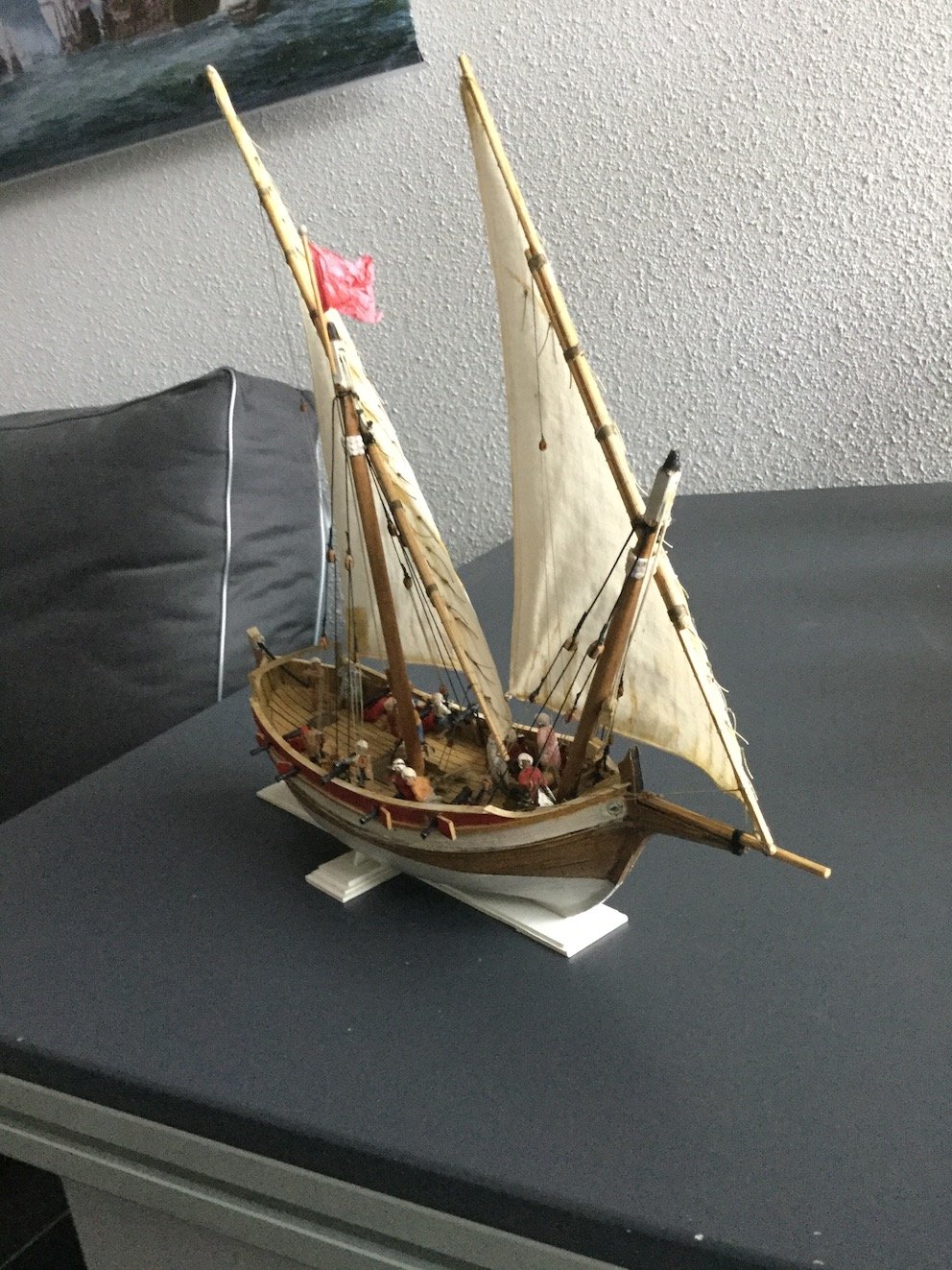
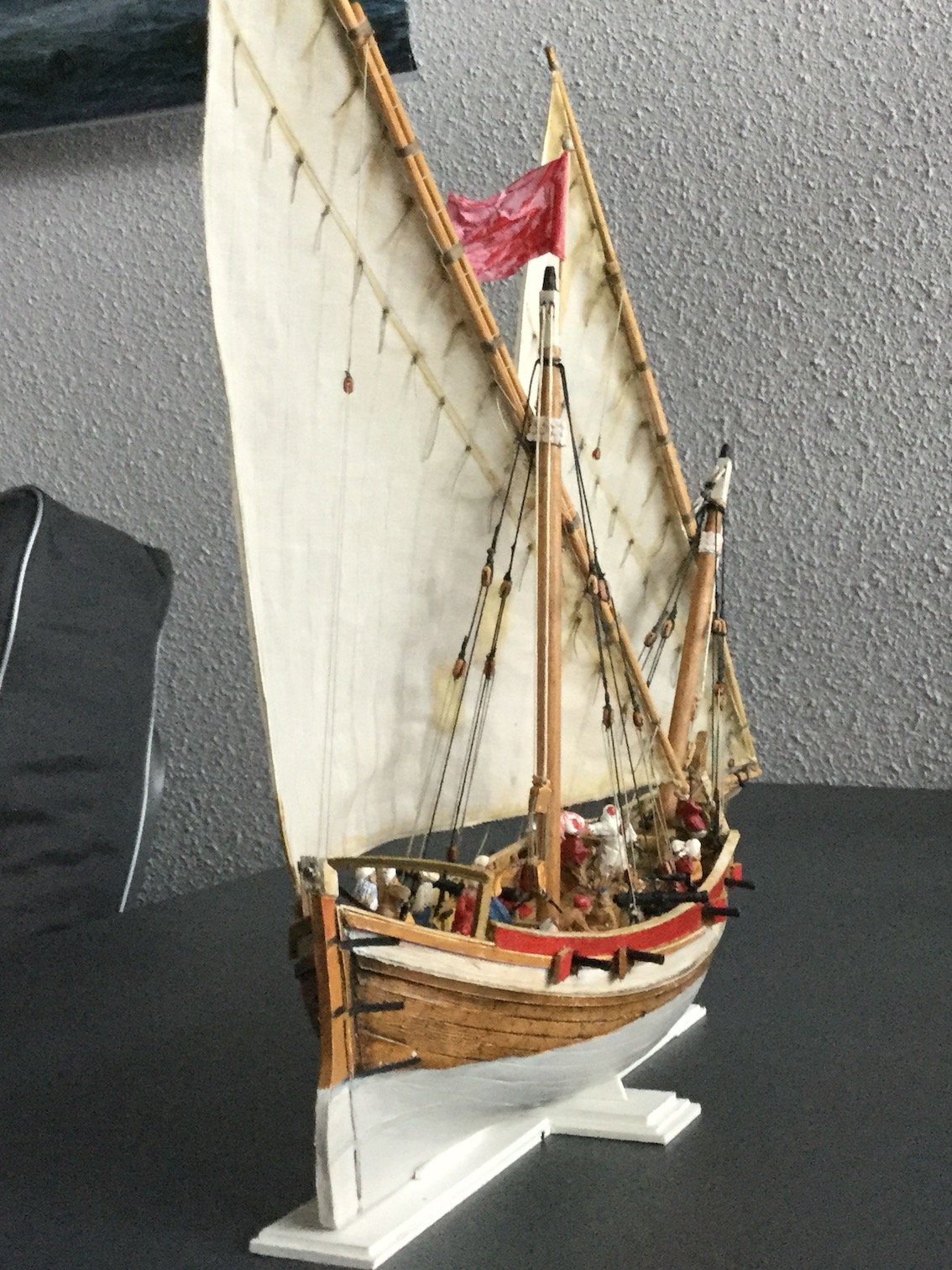
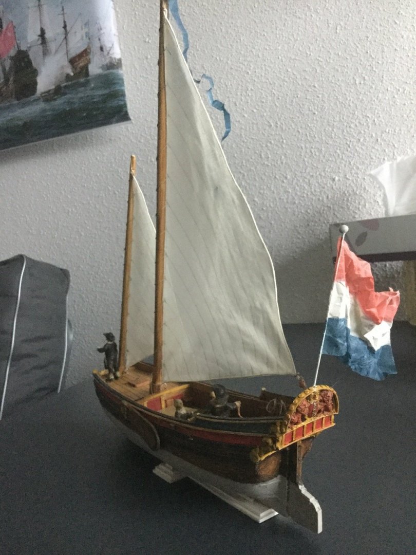
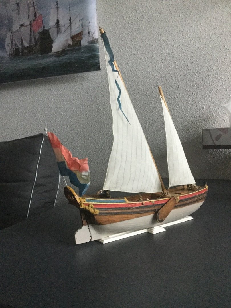
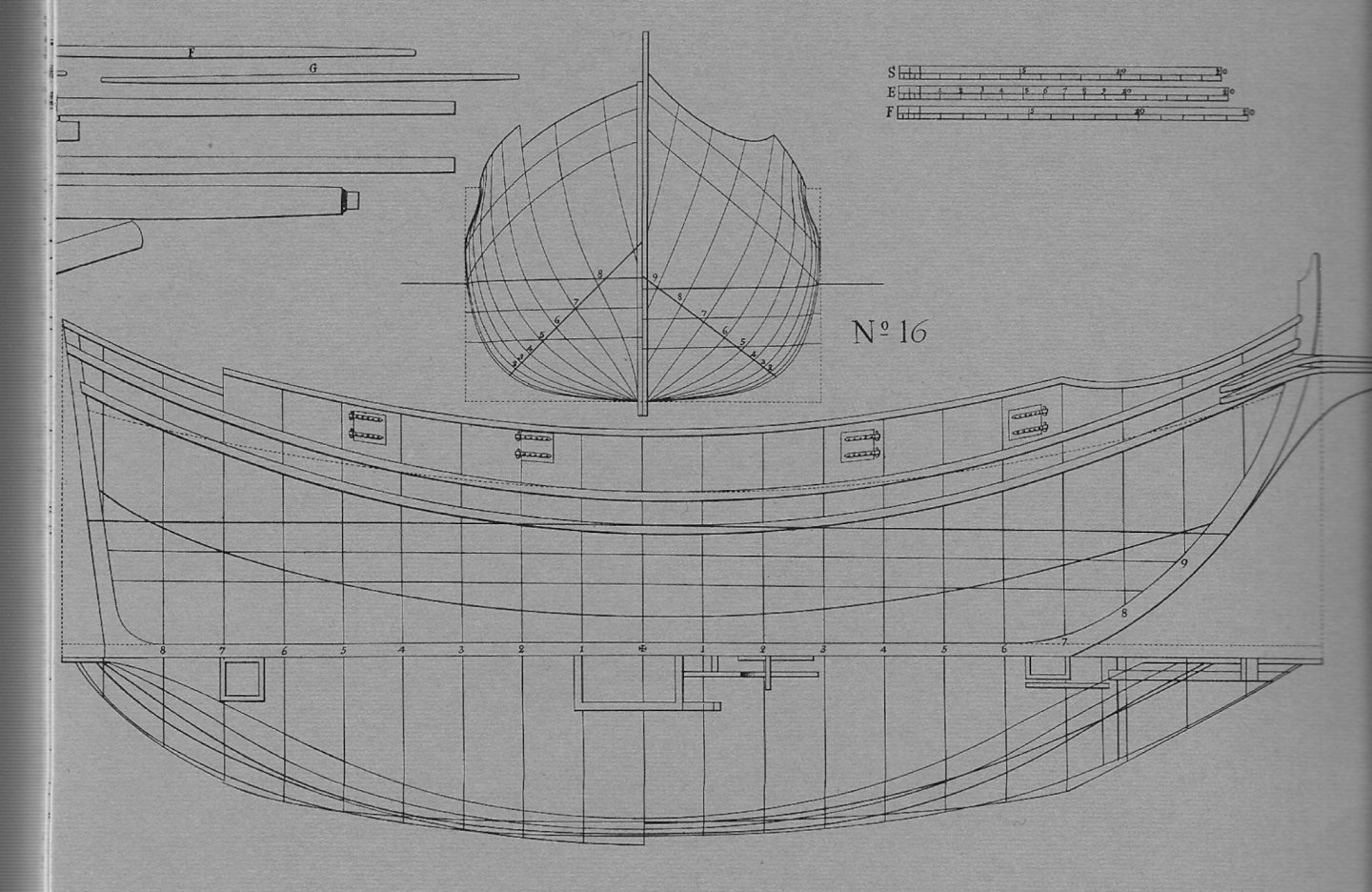
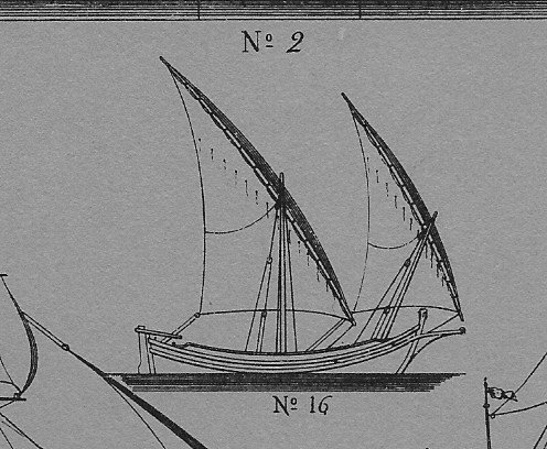
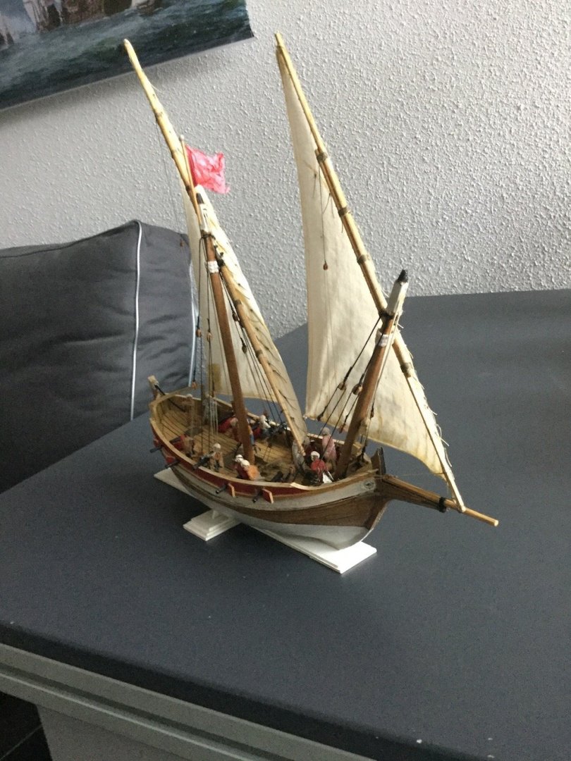
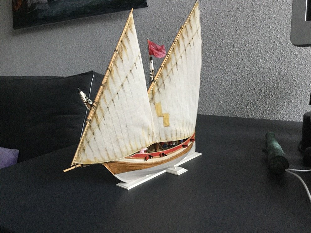
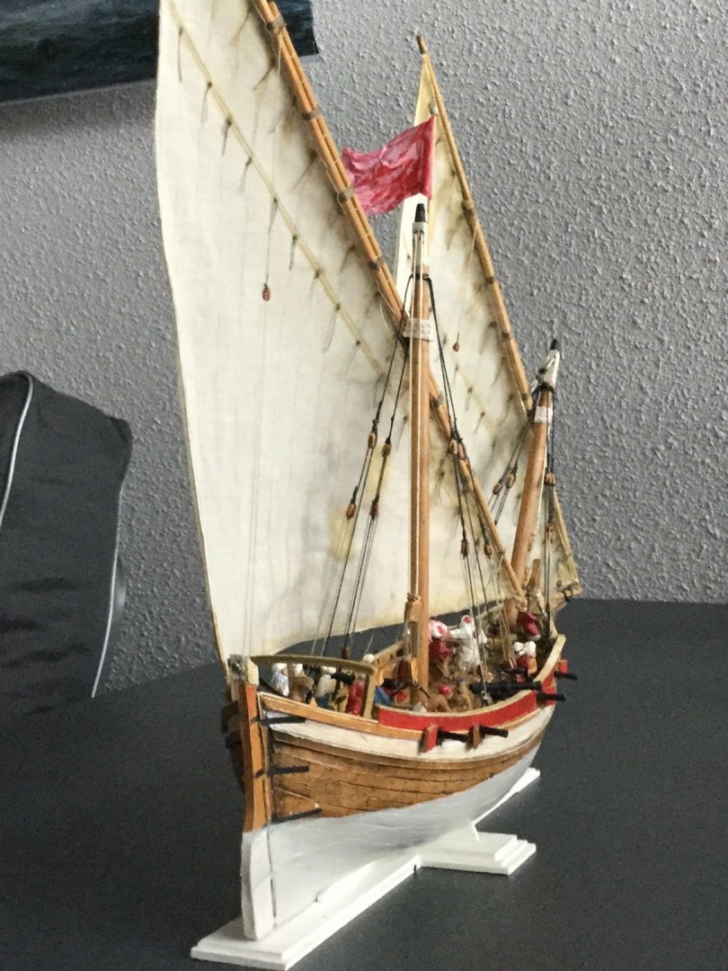
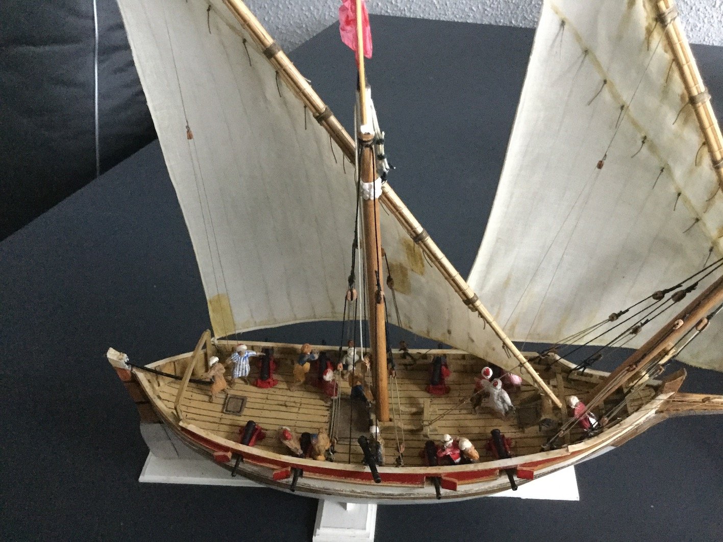
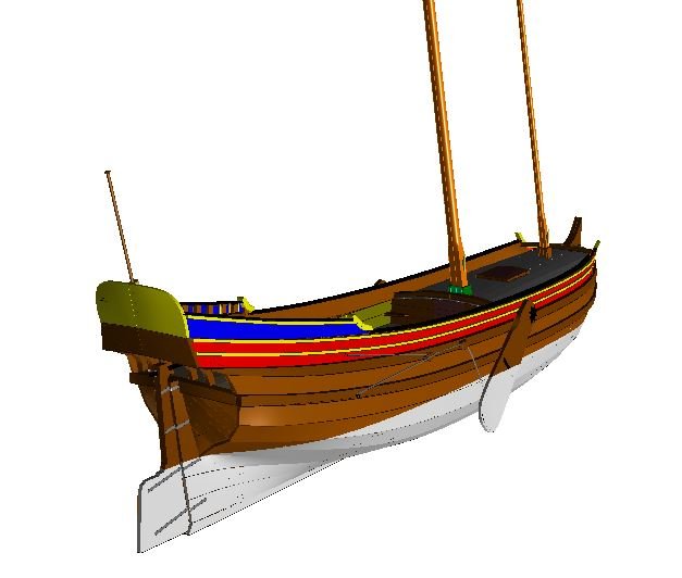
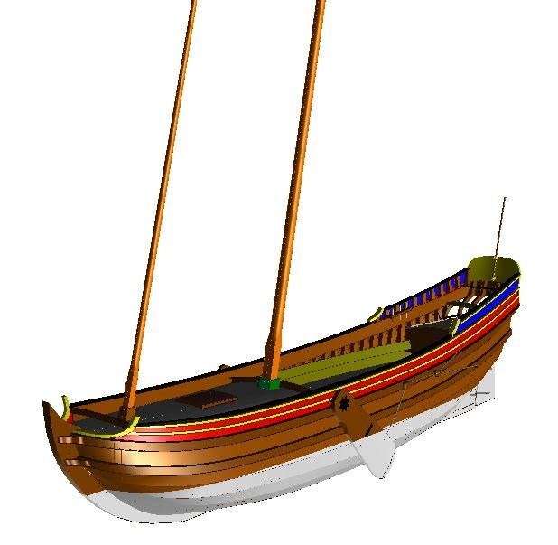
I left this thread alone for a long time. Not because I lost interest, but there were so many more things on my table (an on my mind actually). First I should get back to the discussion about the materials used for sails. I always used a very fine linen cloth to bellow it with starch and a hair dryer, but the bottom of my stock becomes visible and wefalck suggested I might give paper a try. In itself that seemed logical, as I am using paper for the hulls as well, but I never found my way in 'building' sails. A former colleague at the museum directed me to a gentleman in Haarlem (also a restorer) who had stocks of all sorts of paper. Indeed he was kind enough to supply me with some various sizes of wonderful hand made Japanese paper. I tried to make sails with it, but never succeeded in producing a real natural shape with it. Another former colleague sent me new textile material. Not exactly what I used before, but very well suitable for my purposes. So I made new sails for the yacht with it. Originally the question of the material used arose because my sails always look too clean and tidy. I thought it was impossible to apply paint after I used starch to get a natural shaped sail. For reasons of practicing Seahorse's method of double planking paper hulls without the use of filler I needed draughts of a simple vessel. I chose a tartan from Chapman's wonderful collection of draughts Architectura Navalis Mercatoria because of its simple shape and I successfully applied Seahorse's method in the construction of the hull (thank you Tomek). Rigging a lateen sail ship is very quick compared with square rigged ships, so I thought I give painting its sails a try. If things went wrong it would not take much time and effort to replace them. Anyway, painting starched sails with Acrylic paint appeared to be possible indeed, although I need a lot of practice before the result will be really satisfying. I like this small vessel with its exiting lines very much and wonder why I always get back to Dutch vessels. Probably because foreign ones ask so many more questions I cannot answer than Dutch ones... A week later my son and I received a request to do a book sleeve for a book about a fluit ship that was taken by a North African corsair. Pure coincidence. Once the real pictures are taken and Emiel has done his graphic job I will show the results. In the mean time my miracle-Belgium friend Rene Hendrickx finished the 3D model of the pleasure vessel and since this little boat is still the subject of this thread (believe it or not) I can offer the draught to anyone who wants to build this lovely ship type and we even have the shape of the planks right now. If you have the free downloadable shipbuilding program DELFTShip on your 64-bits computer, I can even send you the file, so you can view this model in 3D inside and out. Just send me a PM in case you are interested. Back to the working table, where a Dutch 1600 galley waits for my attention. Another project I got lured into by my former boss at the museum, Peter Sigmond, who is about to publish a book about that stormy period in Dutch history. But that model is again part of a totally different story, maybe another time...
-
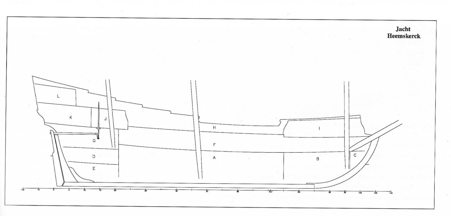
The interior and the decks and their naming are dependent of the sort of fluit. As you know the type was extremely versatile and the internal devision varies just as much. In the case of the Zeehaen, a VOC fluit, it is very much like the usual devision. A - Hold B - Cable tier C - Hell (small compartment used as detention space) D - Cheese and bread room E - Powder room F - Lower deck (in Dutch: overloop. comp.: orlop) G - Gun room (In Dutch: konstabelskamer) H - Upper deck (in Dutch: verdek) I - Forecastle (in Dutch: bak) covered by the 'bakdek'. J - Steering stand (in Dutch: schans or stuurplecht) covered by the 'halfdek' K - Captain's cabin (in Dutch: kajuit) L - Upper cabin (in Dutch: hut) covered by the 'campagnedek'. For the simple mostly smaller cargo variant the lower deck was called 'koebrug'. It was only used for storage of goods which have to be kept dry and was not accessible for the crew. The crew's quarters are behind the koebrug and behind that is the cabin, which was used by the whole crew. The skipper used the upper cabin above. On such ships discipline was much different from men-of-war or East-India-men. The crew was small (about 12 men), of which most of them were very familiar, originating from the same village or region. Food was better too and not rationed. I hope this explains it a bit.
- 332 replies
-
- 7
-
-
- fluit
- abel tasman
- (and 1 more)
-
Your project almost starts to resemble a restoration project. 🙂
- 332 replies
-
- 2
-
-
- fluit
- abel tasman
- (and 1 more)
-
Seems to me that at least you should try to get both sides equal. The truth is in the draught...
- 332 replies
-
- 4
-
-
- fluit
- abel tasman
- (and 1 more)
-
Need CAD type program
Ab Hoving replied to Sambini's topic in CAD and 3D Modelling/Drafting Plans with Software
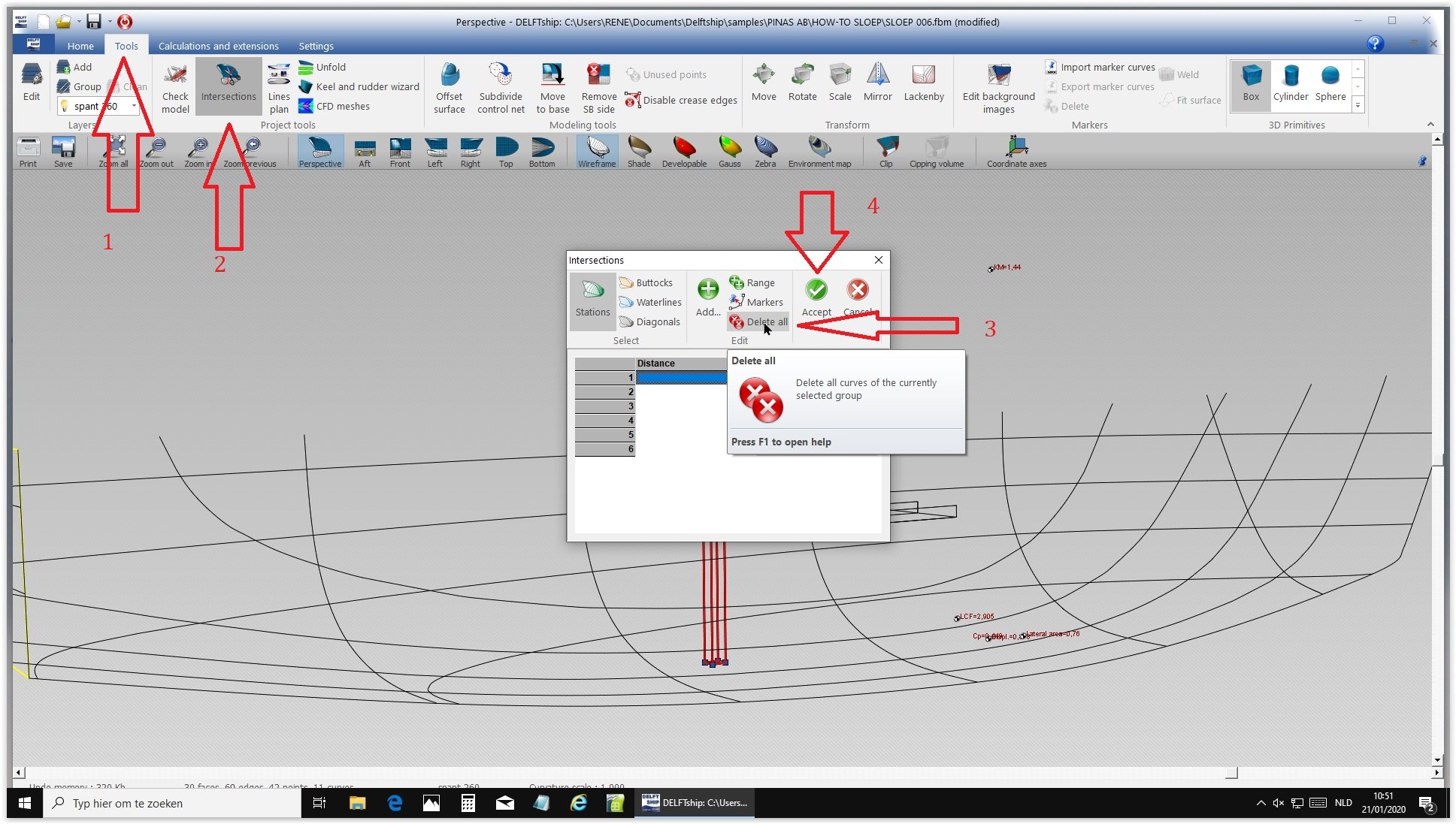
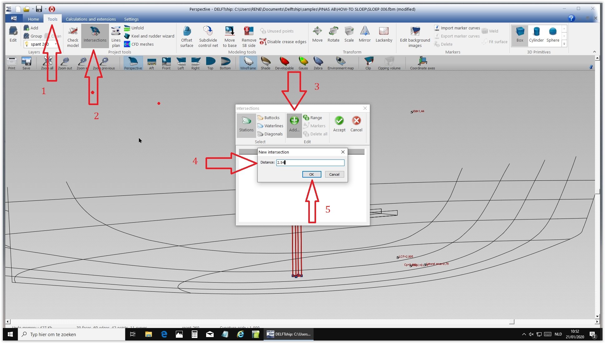
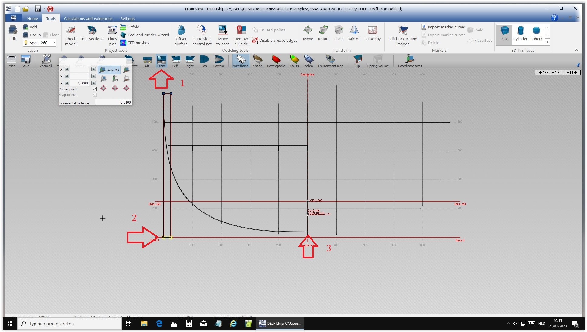
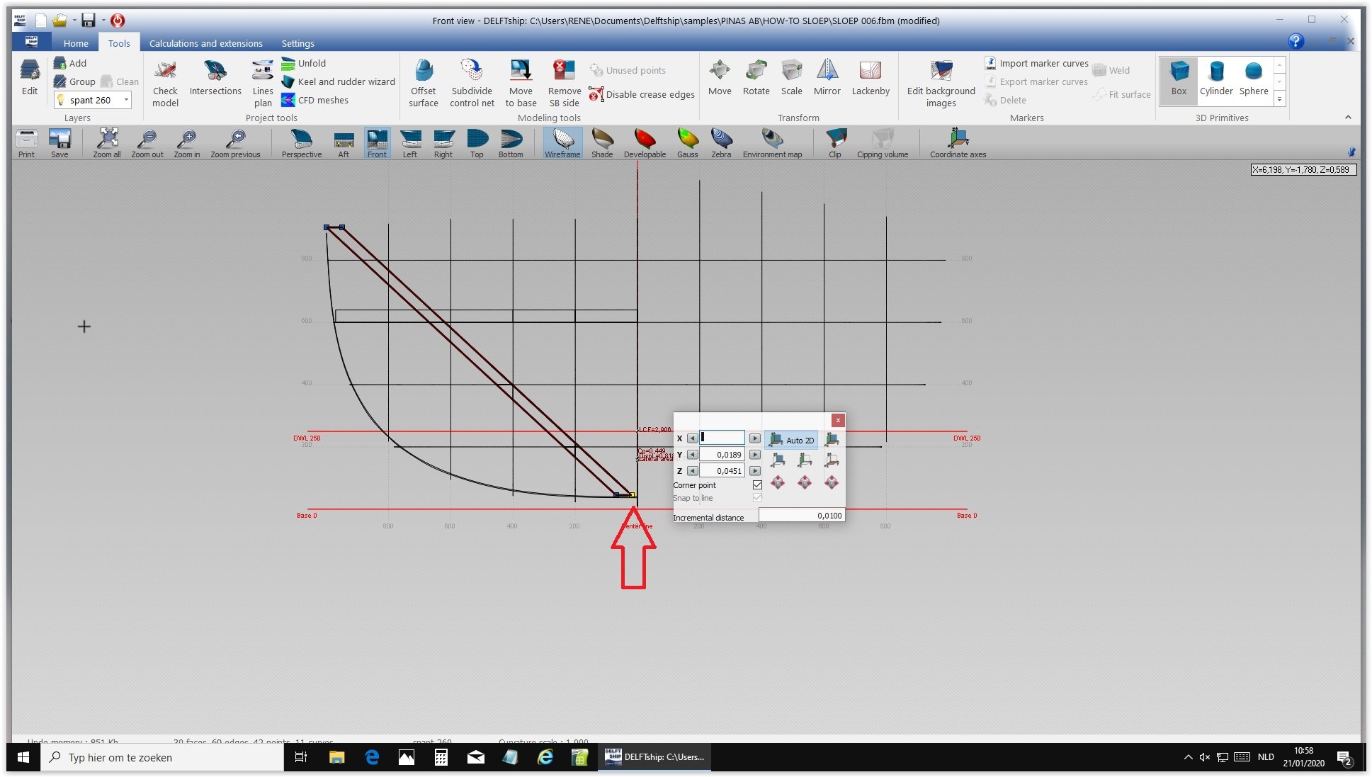
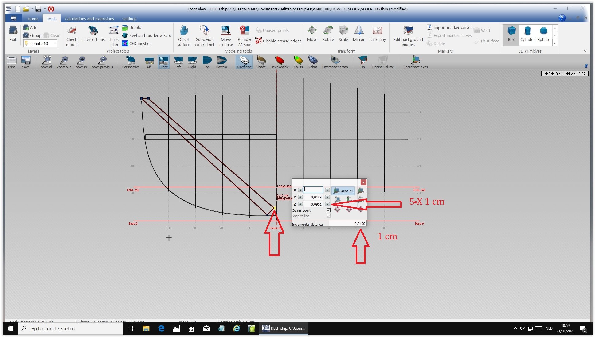
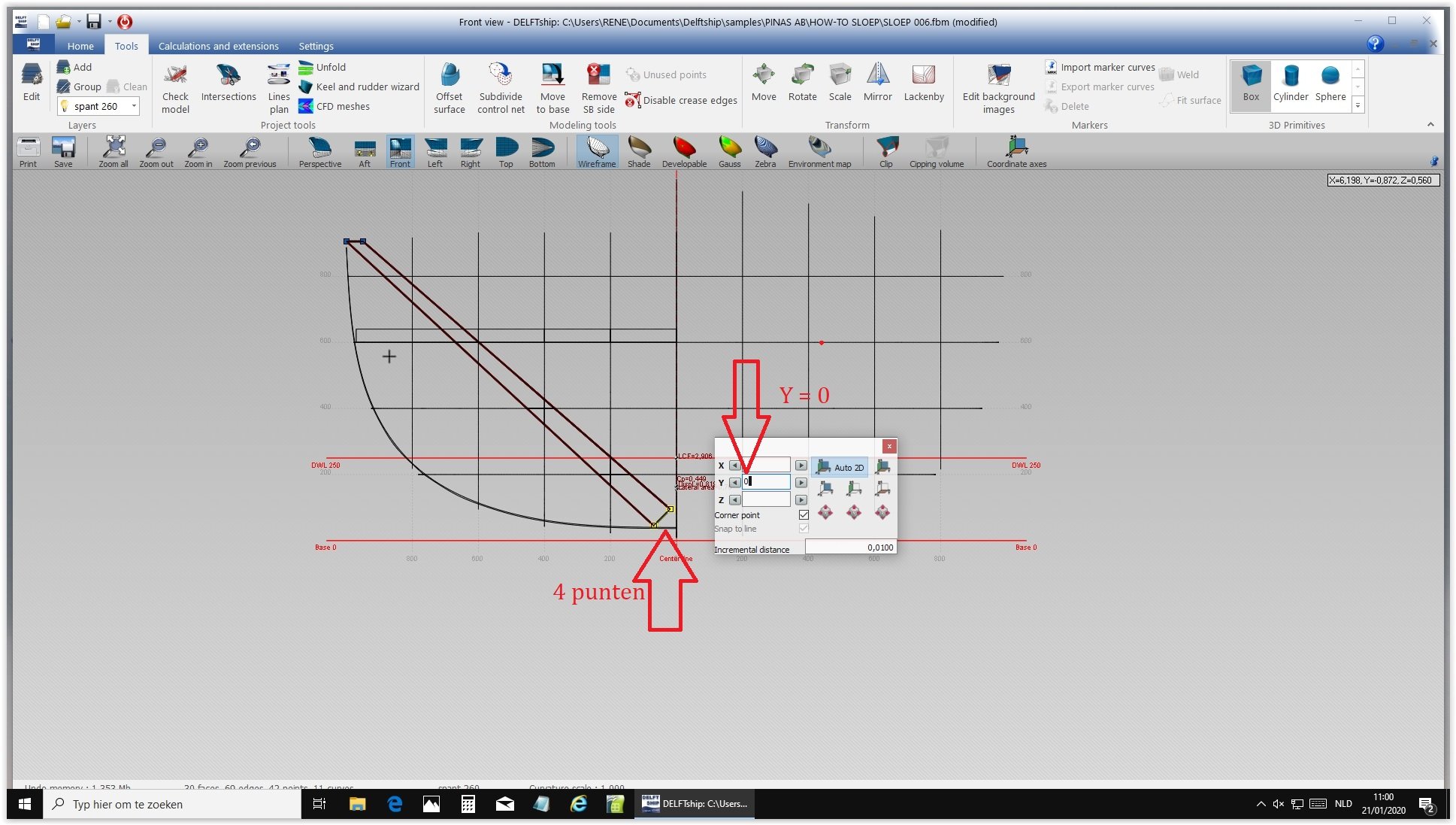
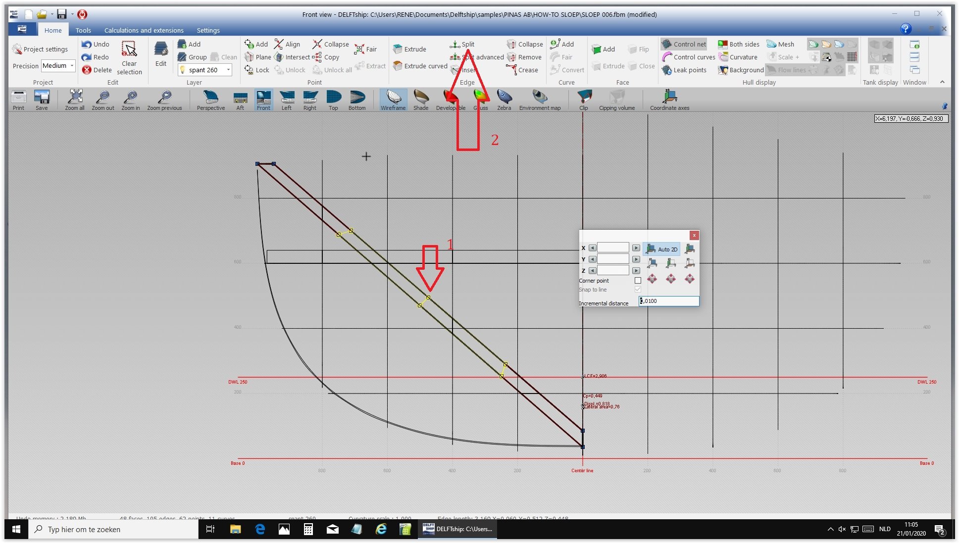
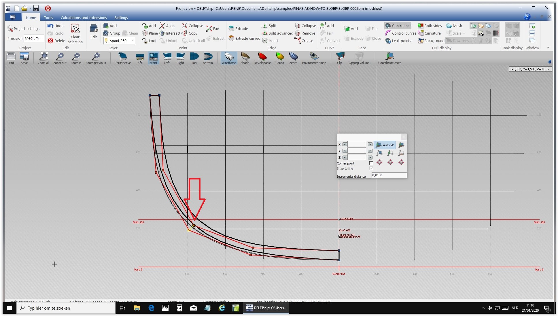
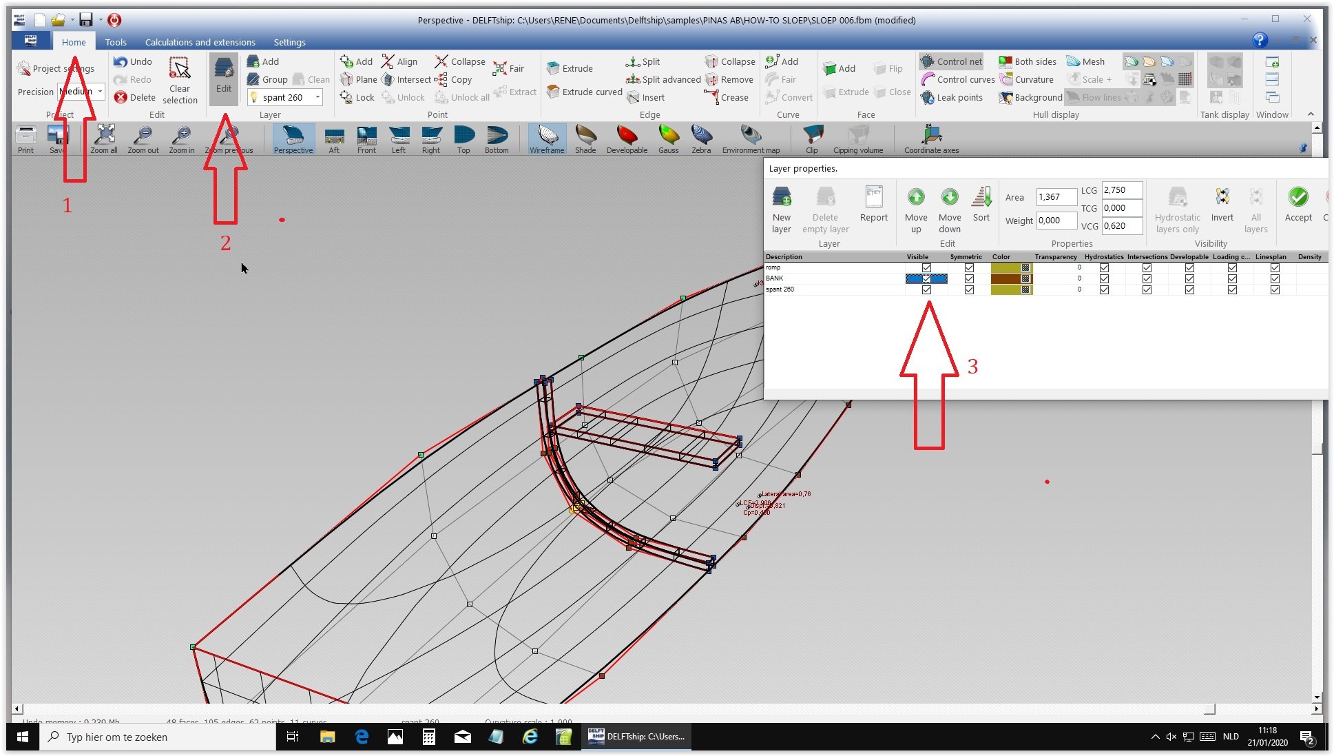
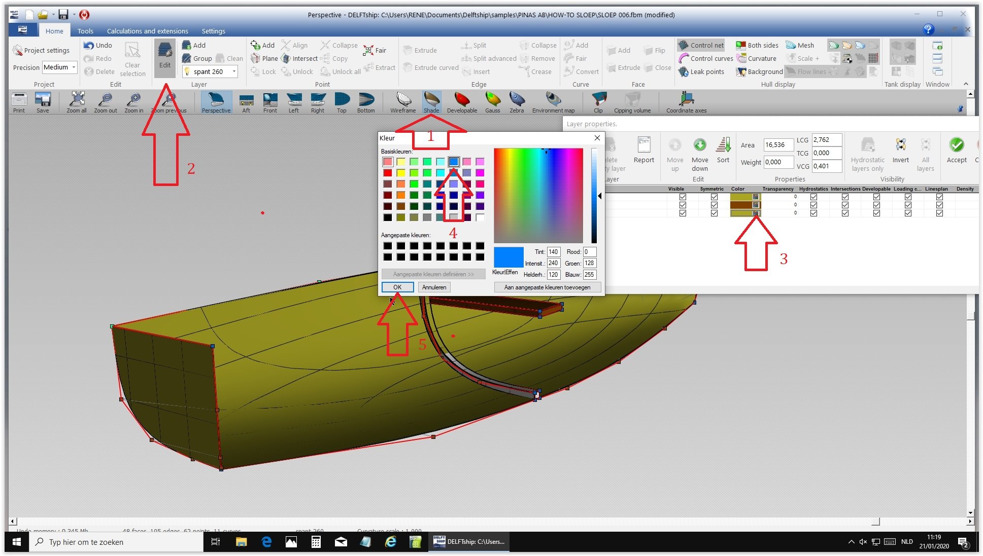
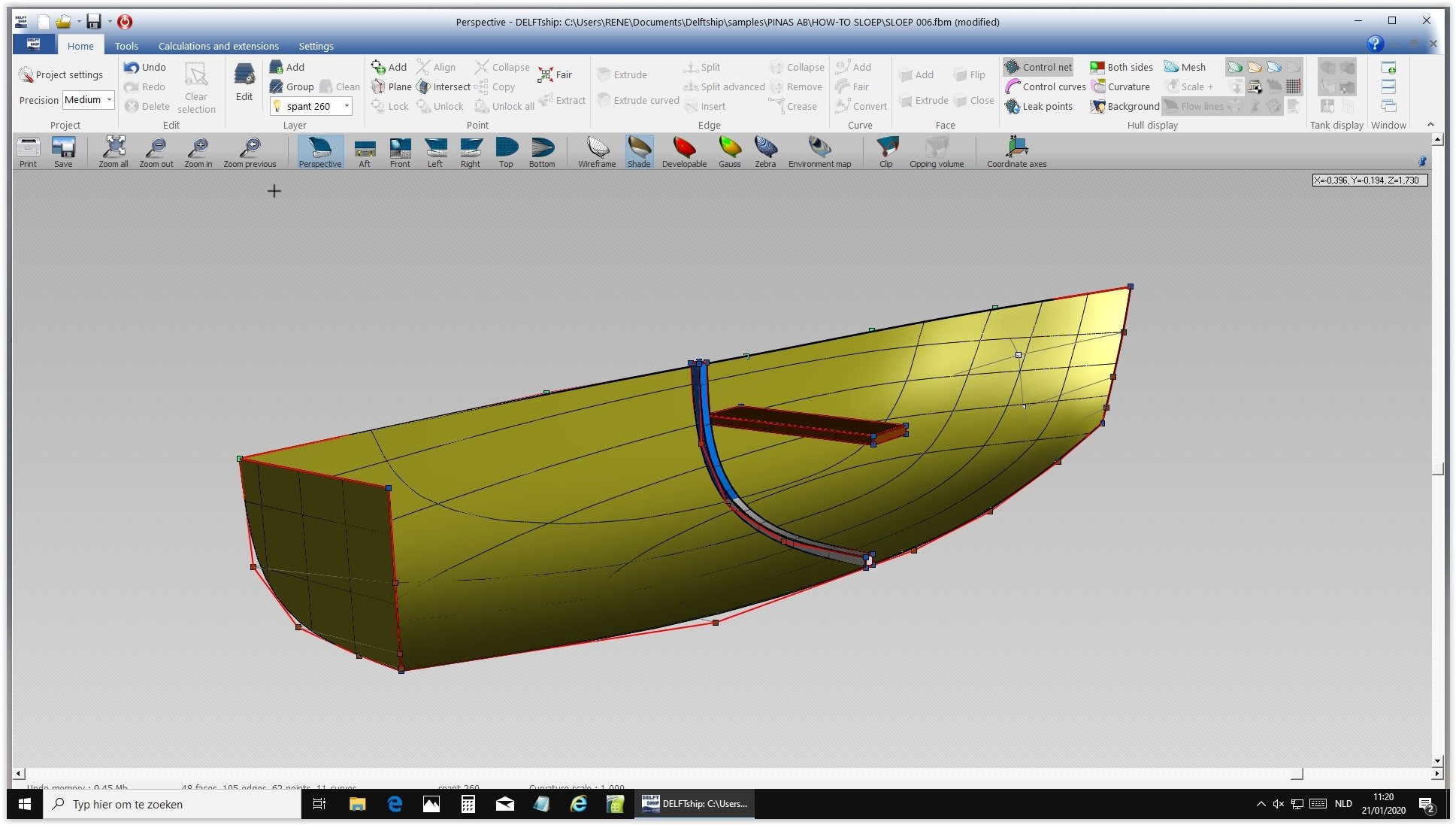
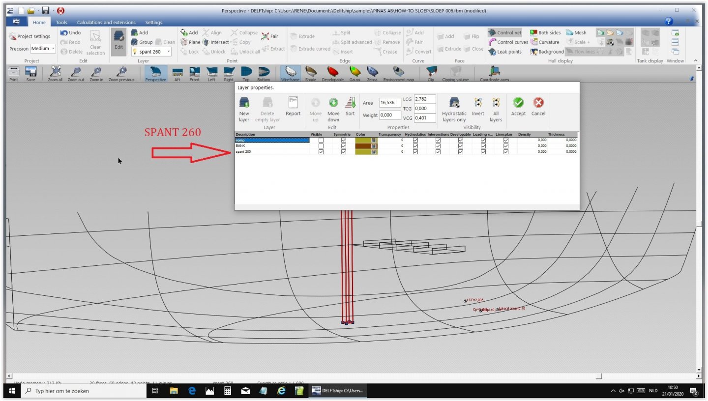
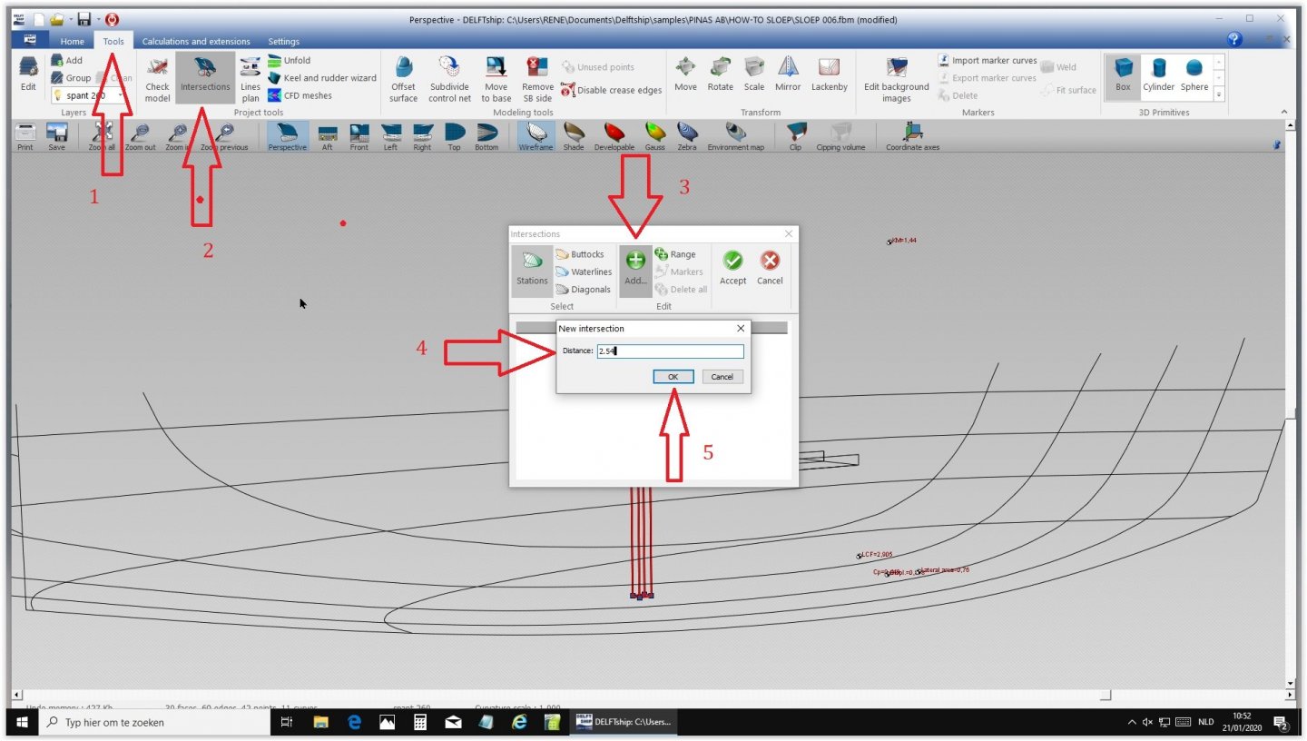
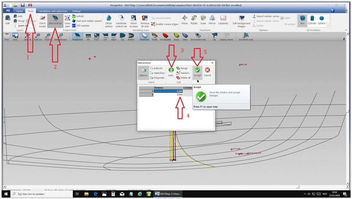
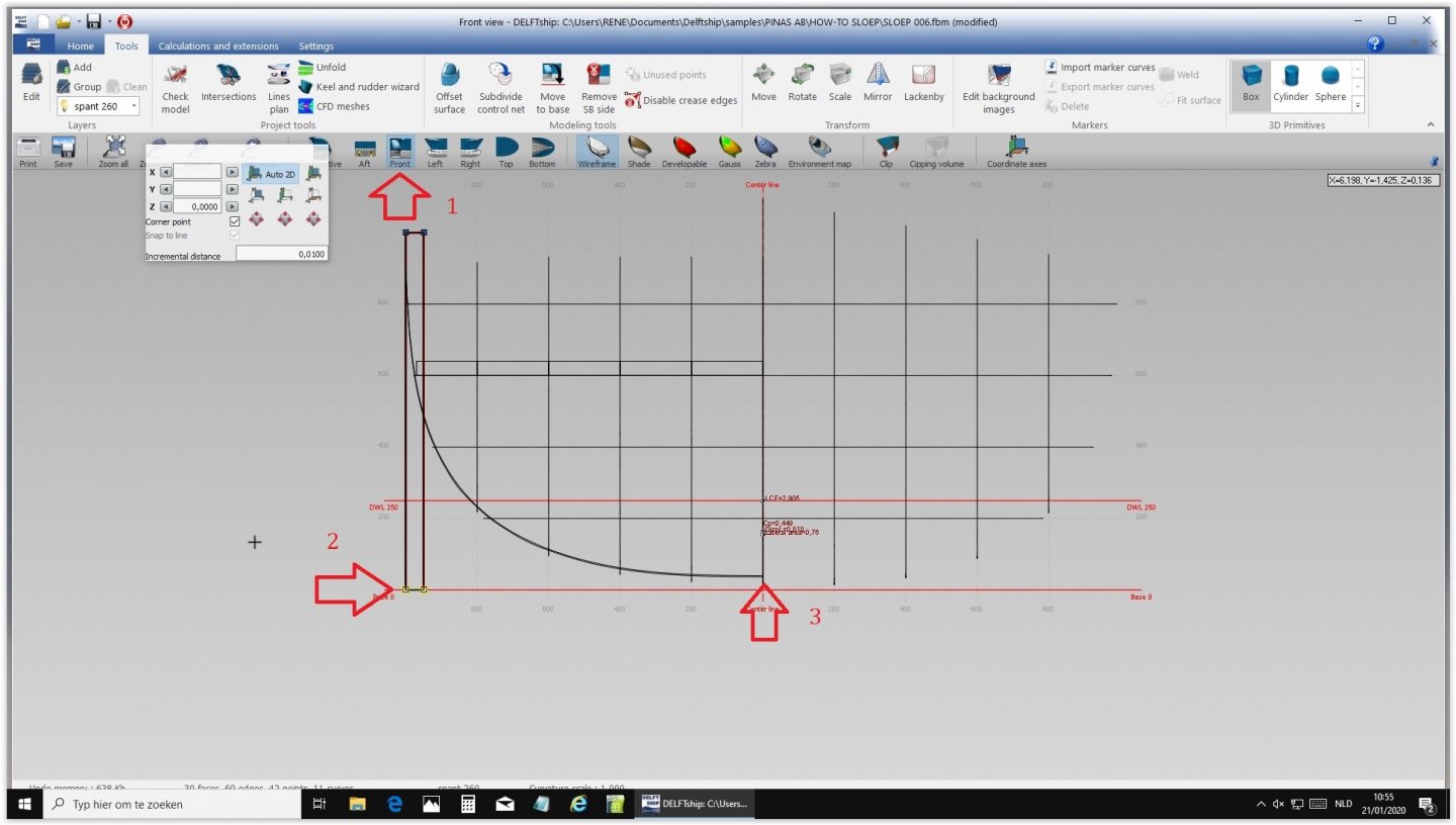
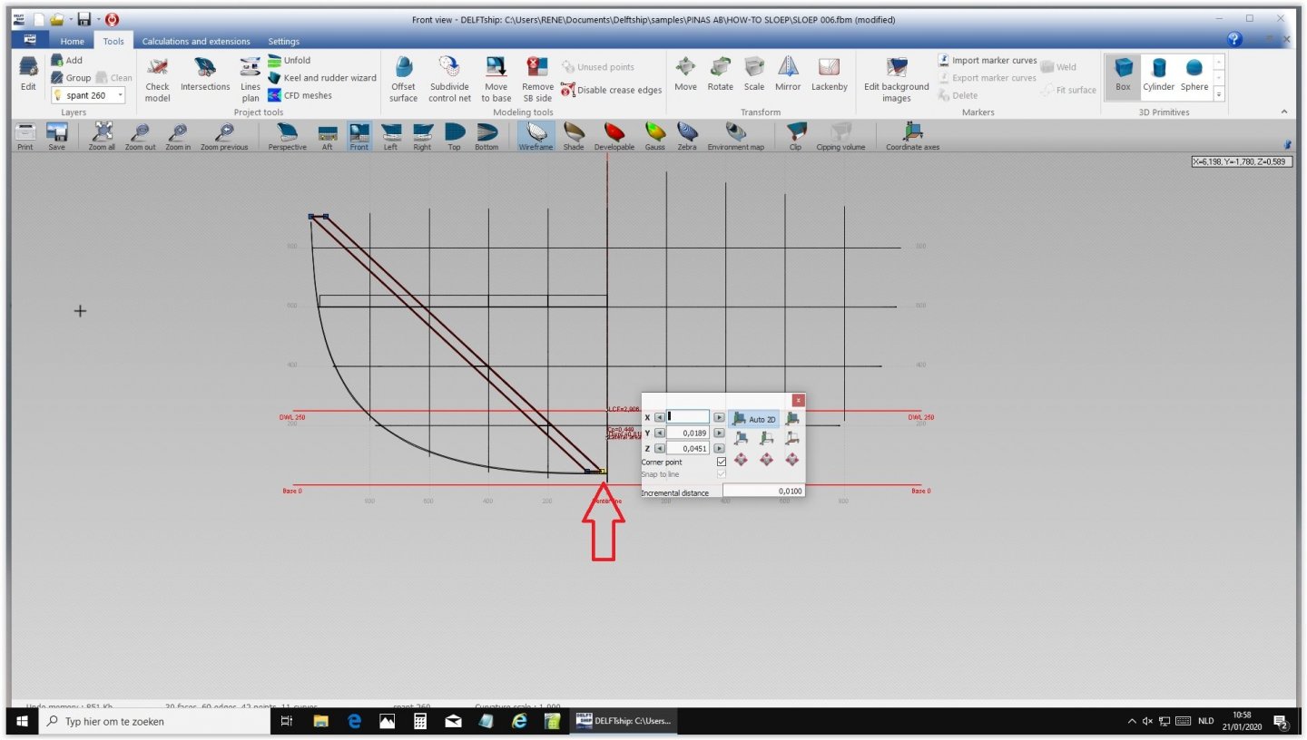
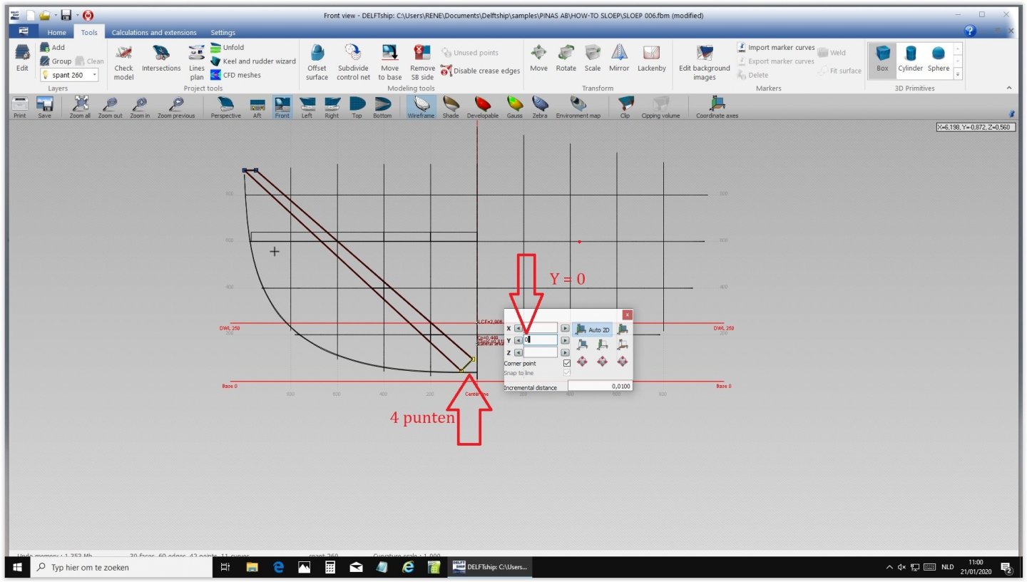
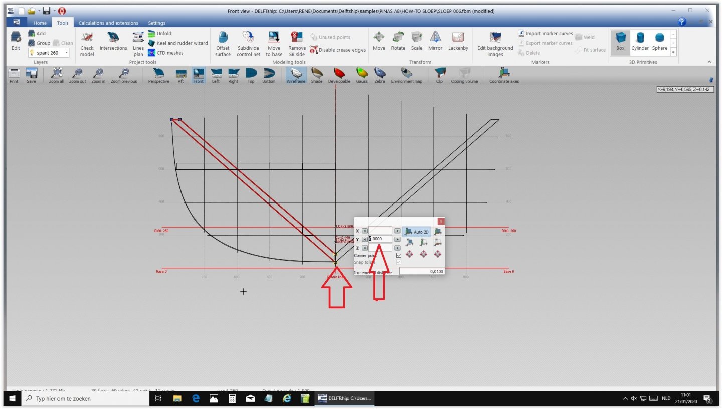
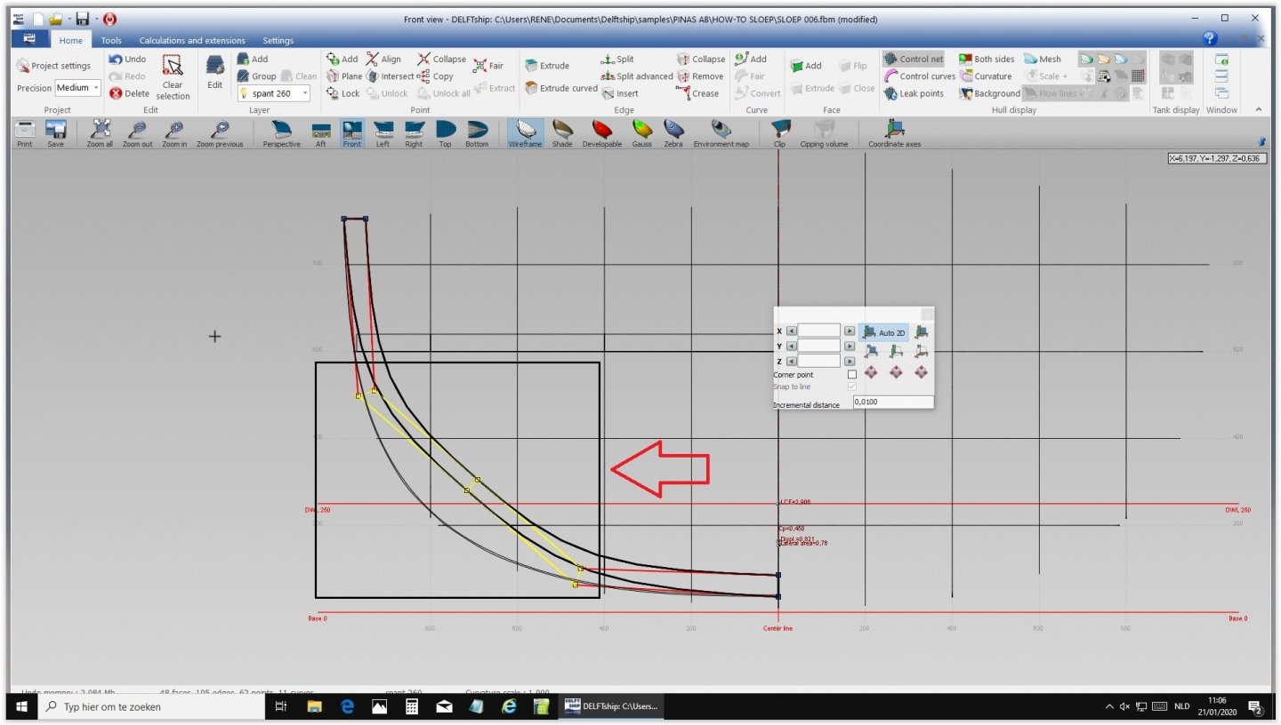
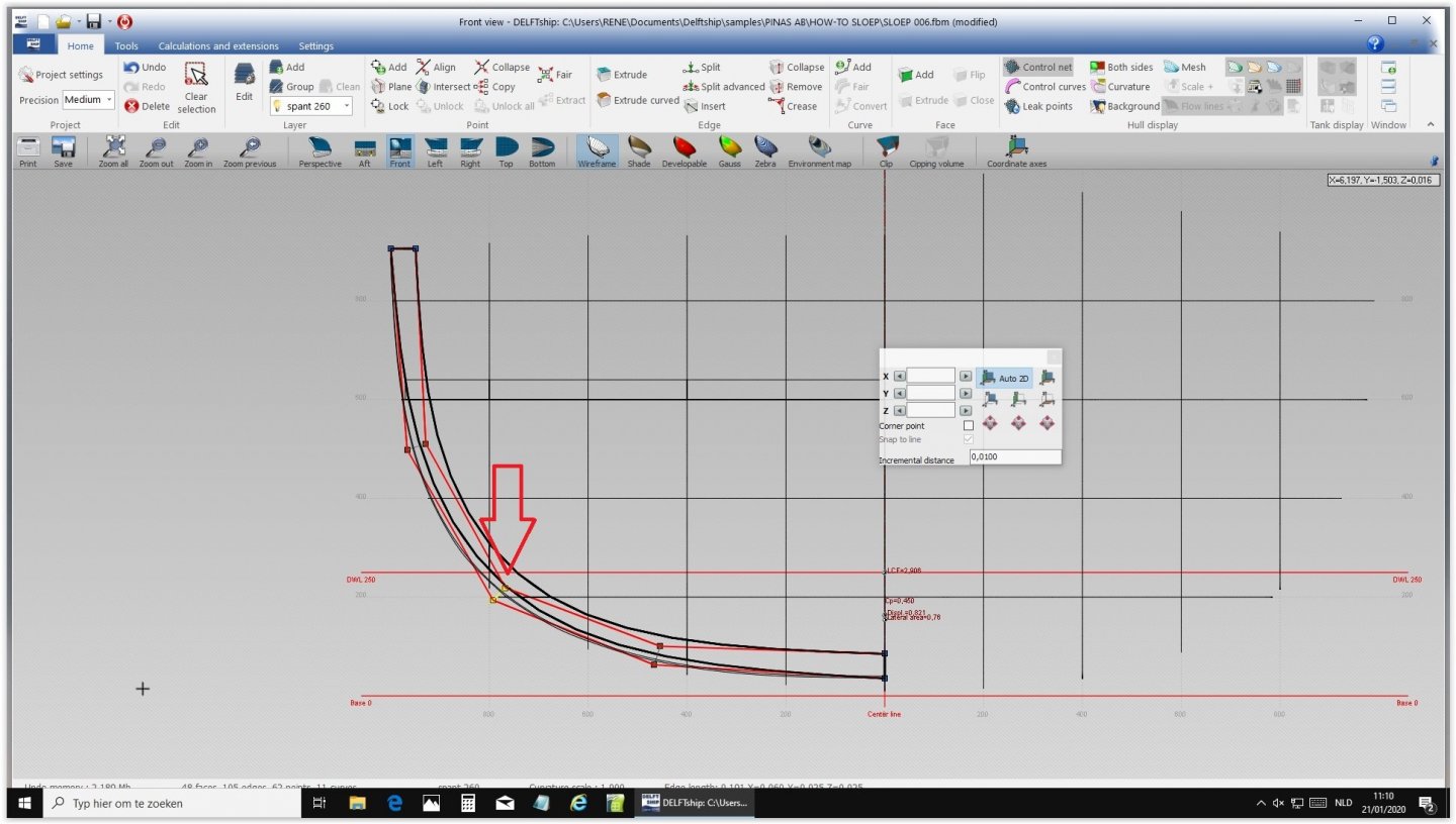
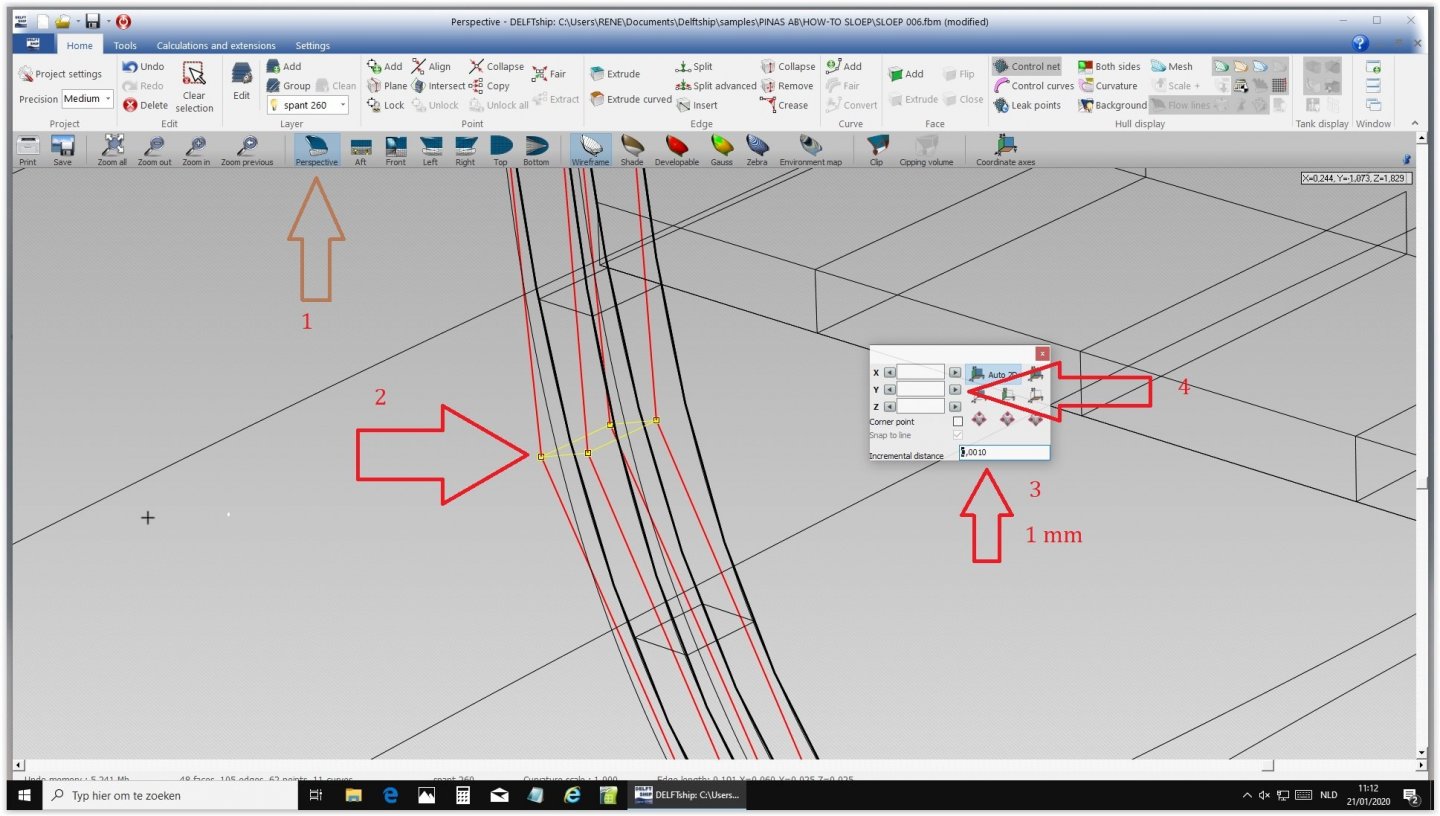
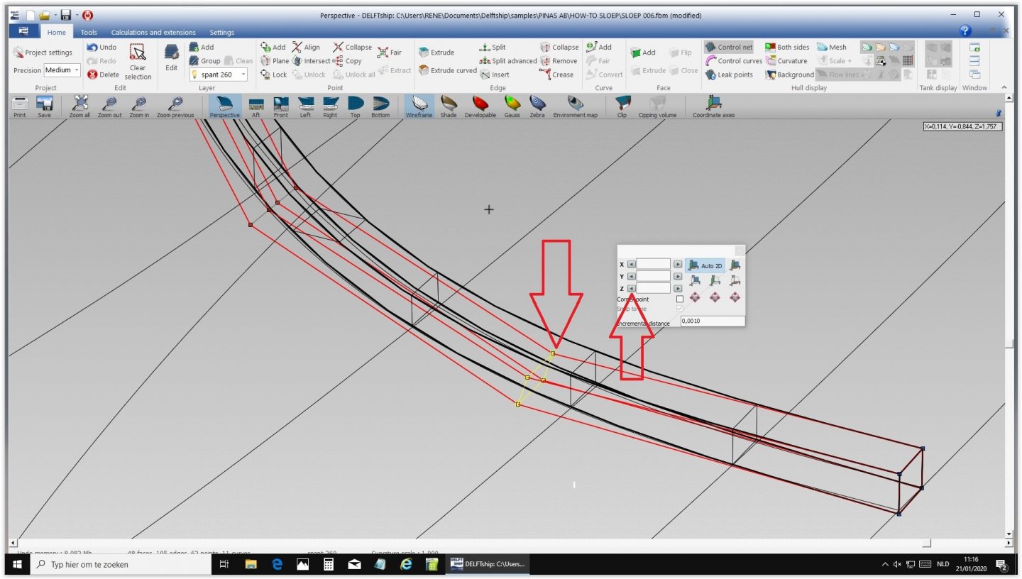
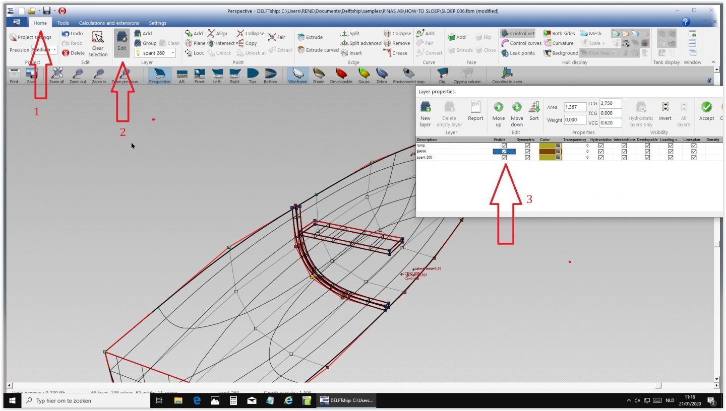
OK, here comes how to create a curved shape inside a vessel. First create a plank the way we did last time. X 2.54/2.60 , Y 0.95/100 , Z 0.00/1.00, new layer Change the name of the new layer Delete all stations Create station 2.54 Create station 2.60 Move the lower side of the plank to the center. Select four lower points by pressing Ctr and dragging with the mouse around the points and move them to the center Select two points and drag them 5 centimeters up Center the four lower points. Drag the four points to the bottom of the frame. Drag these four points to the underside of the frame Select the four long lines and split, and the same for the upper and lower half Select the 12 points that were created this way and drag until the upper and lowerpoints touch the frame. Select the four middle points and drag them till they touch the frame Select Perspective and take the four upper points. Change Y until the lines match Match the lower points by moving Z and Y an equal numbers Make all layers visible again Open Layers and change color A blue frame is made just behind the bench That's how simple it is...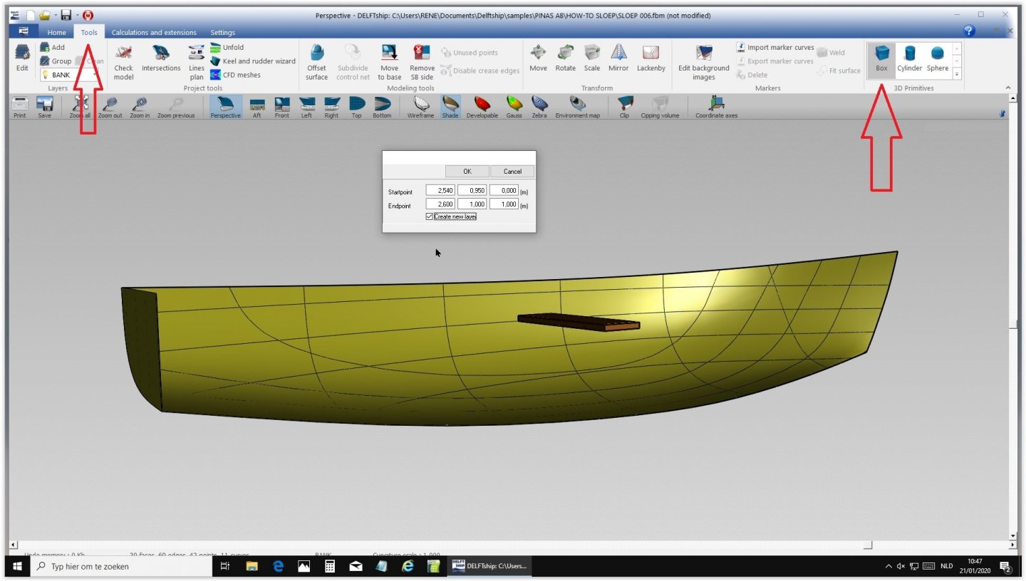


-
Need CAD type program
Ab Hoving replied to Sambini's topic in CAD and 3D Modelling/Drafting Plans with Software
OK Bruce, I will pass your thanks to Rene, he is the man. Ab -
Just a short comment about using iron chains for anchors (though I know I am late): Up to the nineteenth century metallurgic knowledge did not come much farther than mixing ores from various origins: tough metal from Sweden, hard from Spain, all depending of the percentage of carbon. These mixes were always a result of trial and error. Because of that every iron object was tested first: Anchors were dropped on a stone or on an old cannon and if it bended or cracked, it was rejected. Coats of arm were literally shot at with muskets. We had therm in our collection, a dent was proof that the object had passed the test. A chain is as strong as its weakest link. With the knowledge our craftsmen had in those days chains for anchors were more than a risk. One weak link was enough. Stay with rope, please.
-
Need CAD type program
Ab Hoving replied to Sambini's topic in CAD and 3D Modelling/Drafting Plans with Software
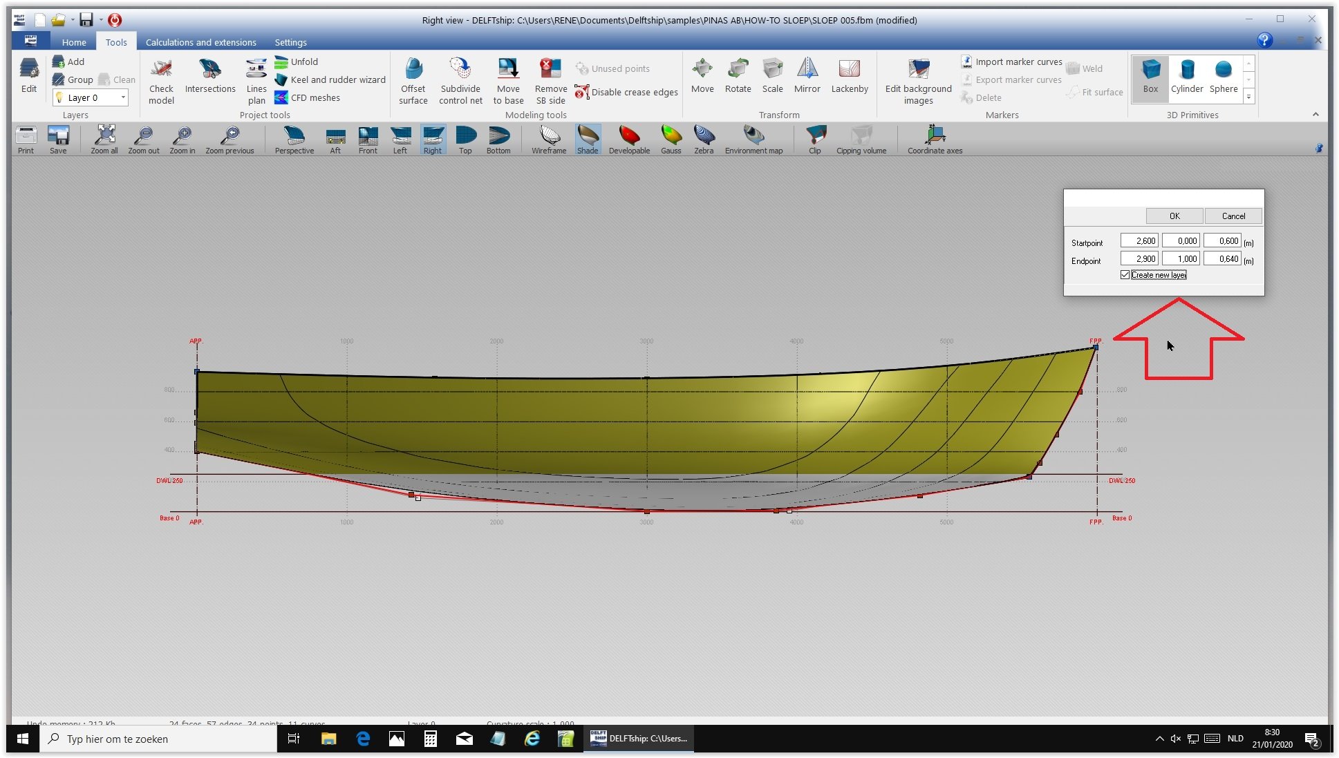
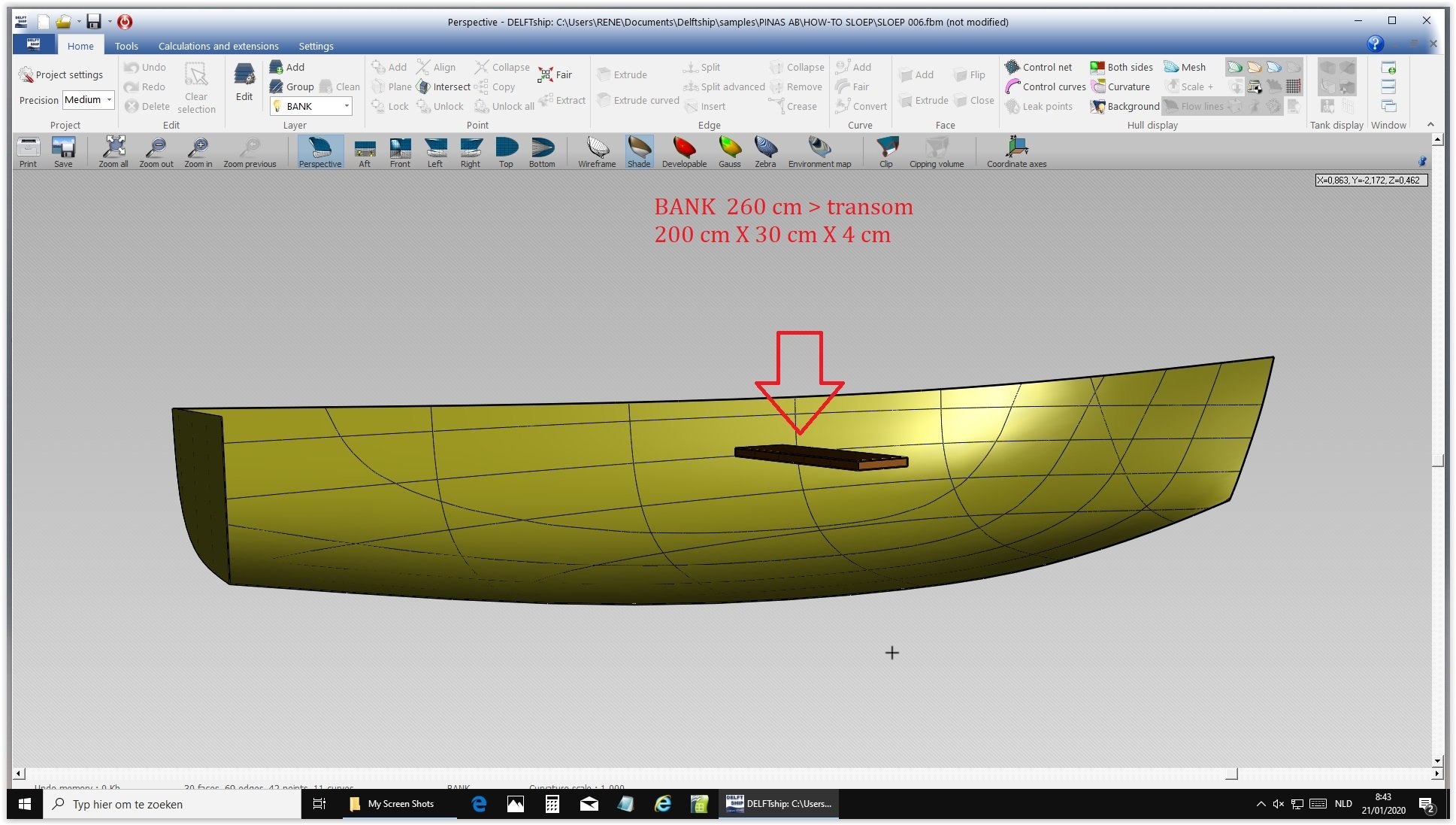
OK, here comes the first lesson in adding objects or parts inside the created 'shell'. Let's for instance create a bench in our vessel at 260 cm from the stern. choose Tool and then Box. In the pop-up screen choose X 2.6 m distance to the stern, X 2.9 for the width of the plank. Y 0 m to the centerline, Y 1 m for the half width of the plank Z 0.6 hight above base line (lowest point of hull, Z 0.64 for the thickness of the plank. Create a new Layer: check. Next time how to create a bended shape, for instance a frame.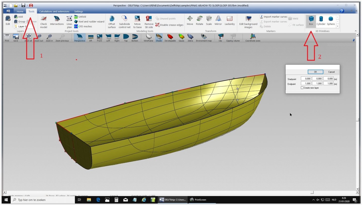


-
Need CAD type program
Ab Hoving replied to Sambini's topic in CAD and 3D Modelling/Drafting Plans with Software
The problem with Rene's command of foreign languages is that he, being Belgium, is more oriented toward French than toward te English language. That's why I am trying to intervene in passing his considerable knowledge to this forum in the appropriate language. Be patient, I am sure he is willing to help you out. -
Need CAD type program
Ab Hoving replied to Sambini's topic in CAD and 3D Modelling/Drafting Plans with Software
Every part of the ship I showed was made with DELFTship. If you want to know how, I will have to ask Rene, but I think there is a function in the program that allows you to start with a choice of several shapes, after which they can be 'deformed' as you like. -
Congratulations Markus. This time it will work. The 'man' 🙂
- 332 replies
-
- 2
-
-
- fluit
- abel tasman
- (and 1 more)
-
Need CAD type program
Ab Hoving replied to Sambini's topic in CAD and 3D Modelling/Drafting Plans with Software
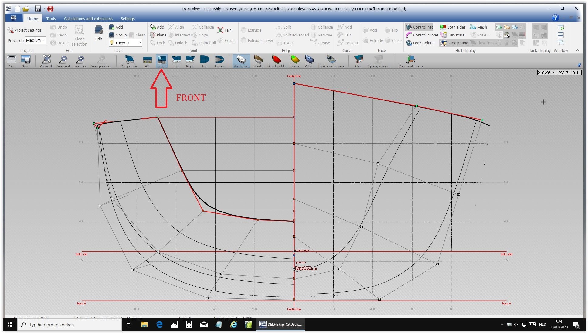
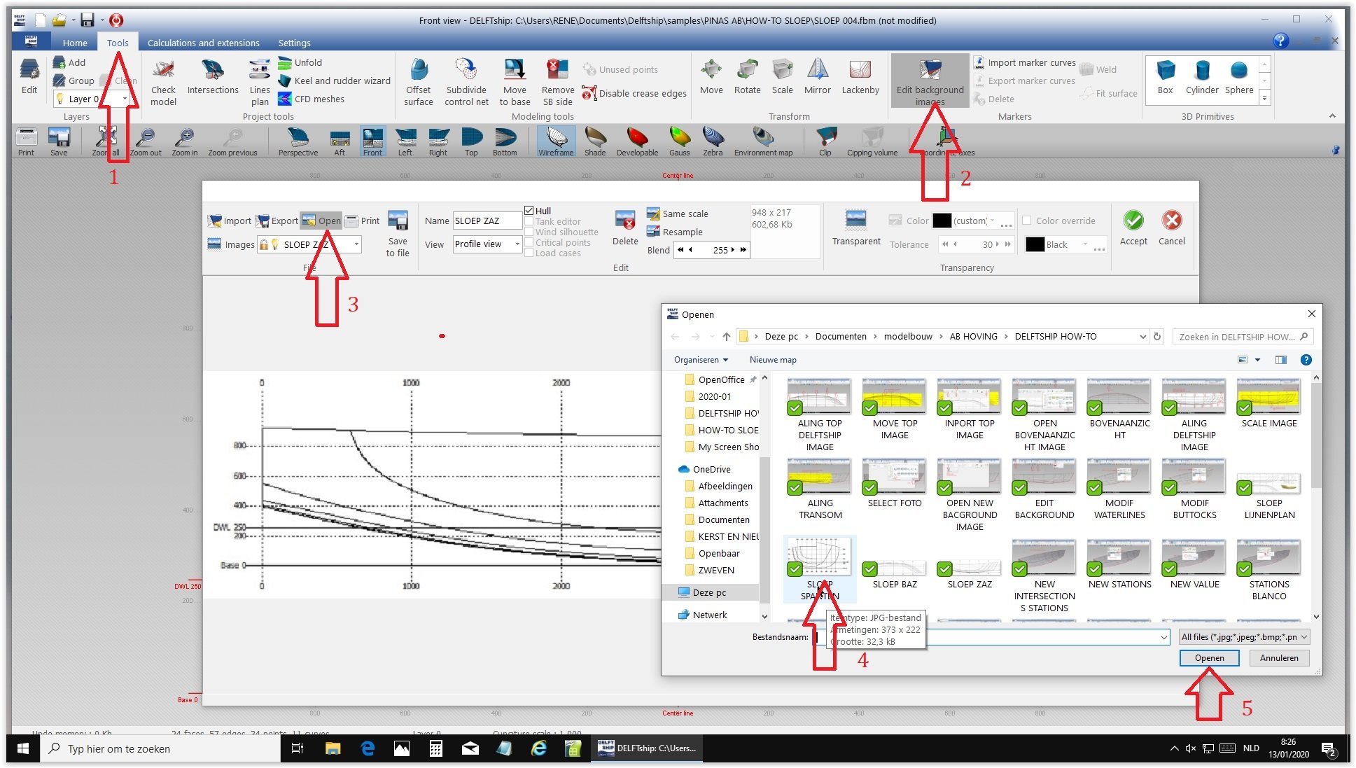
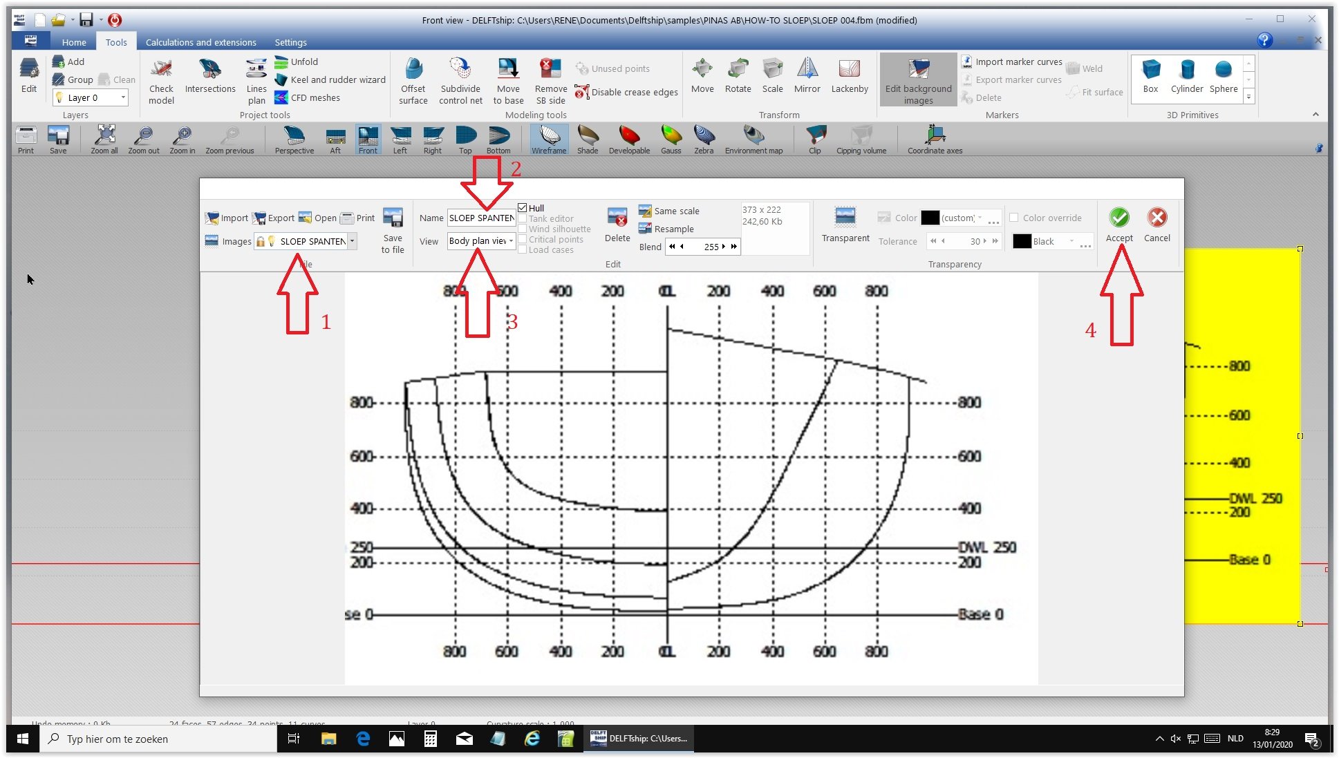
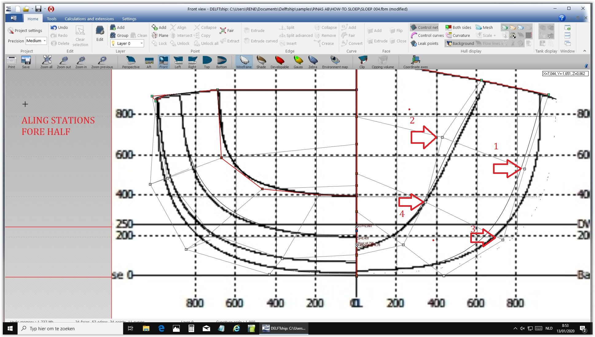
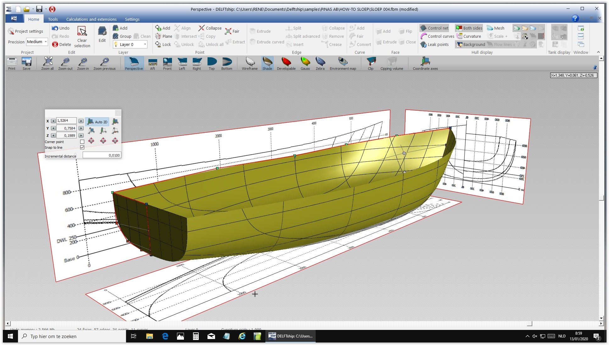
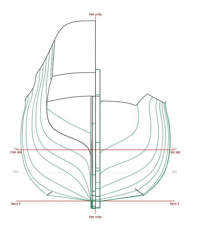
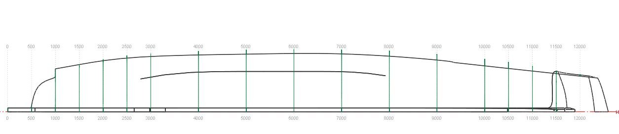
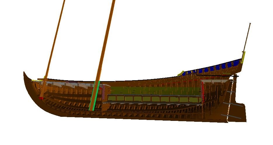
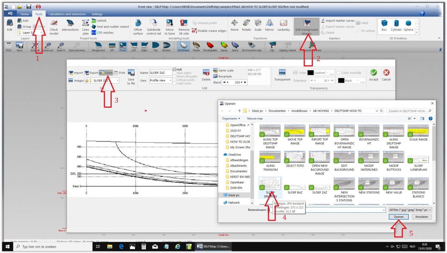
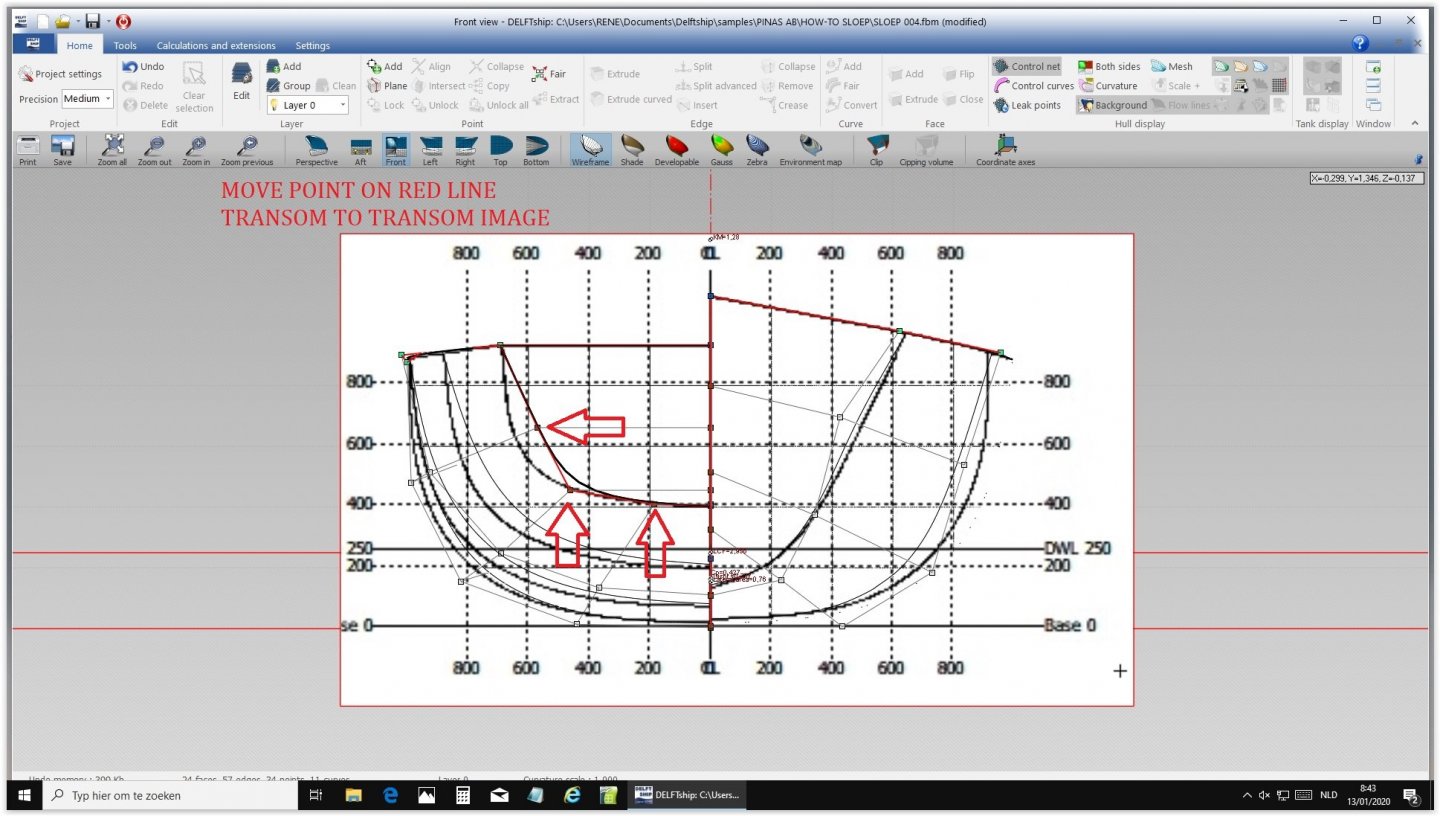
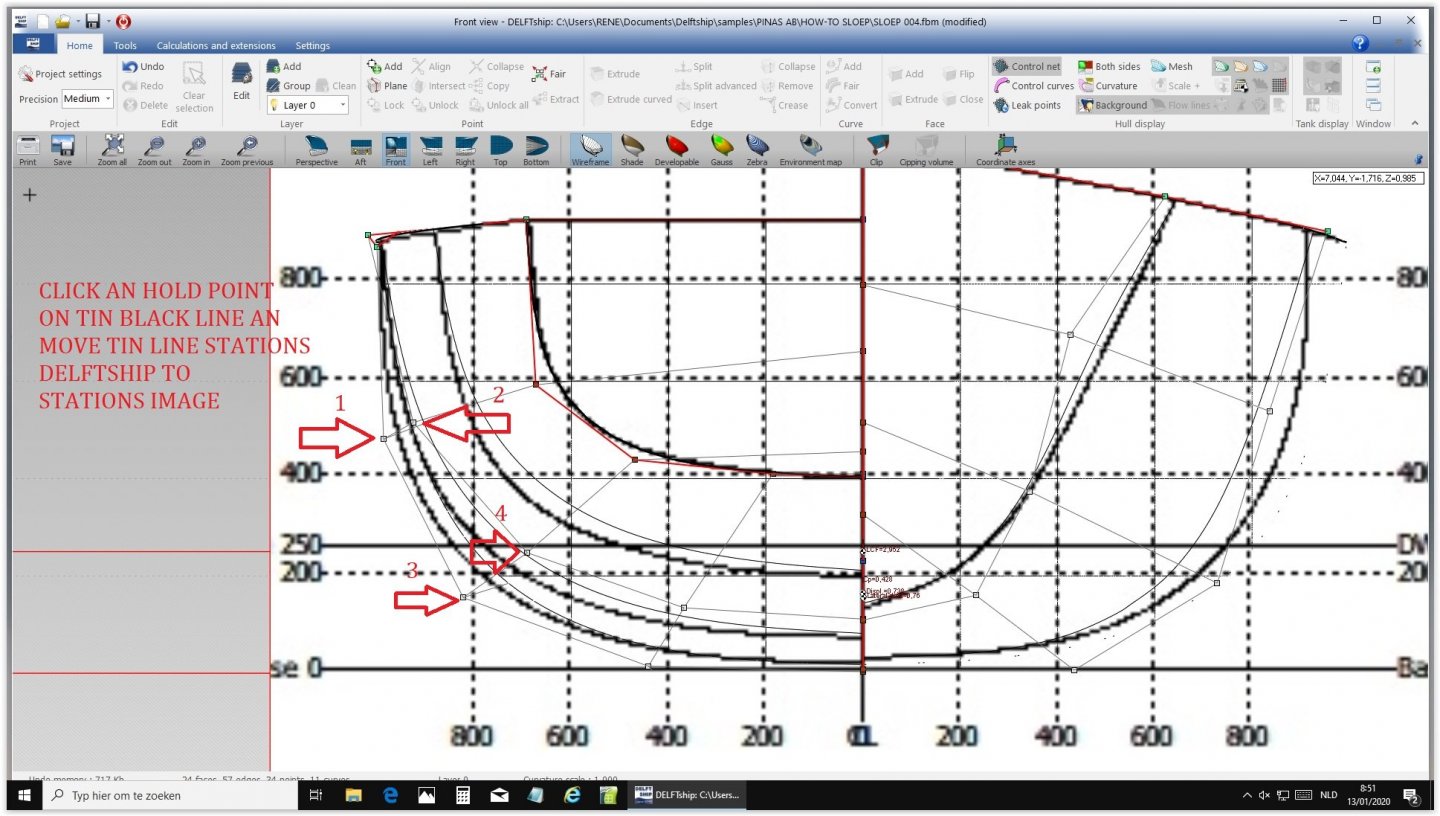
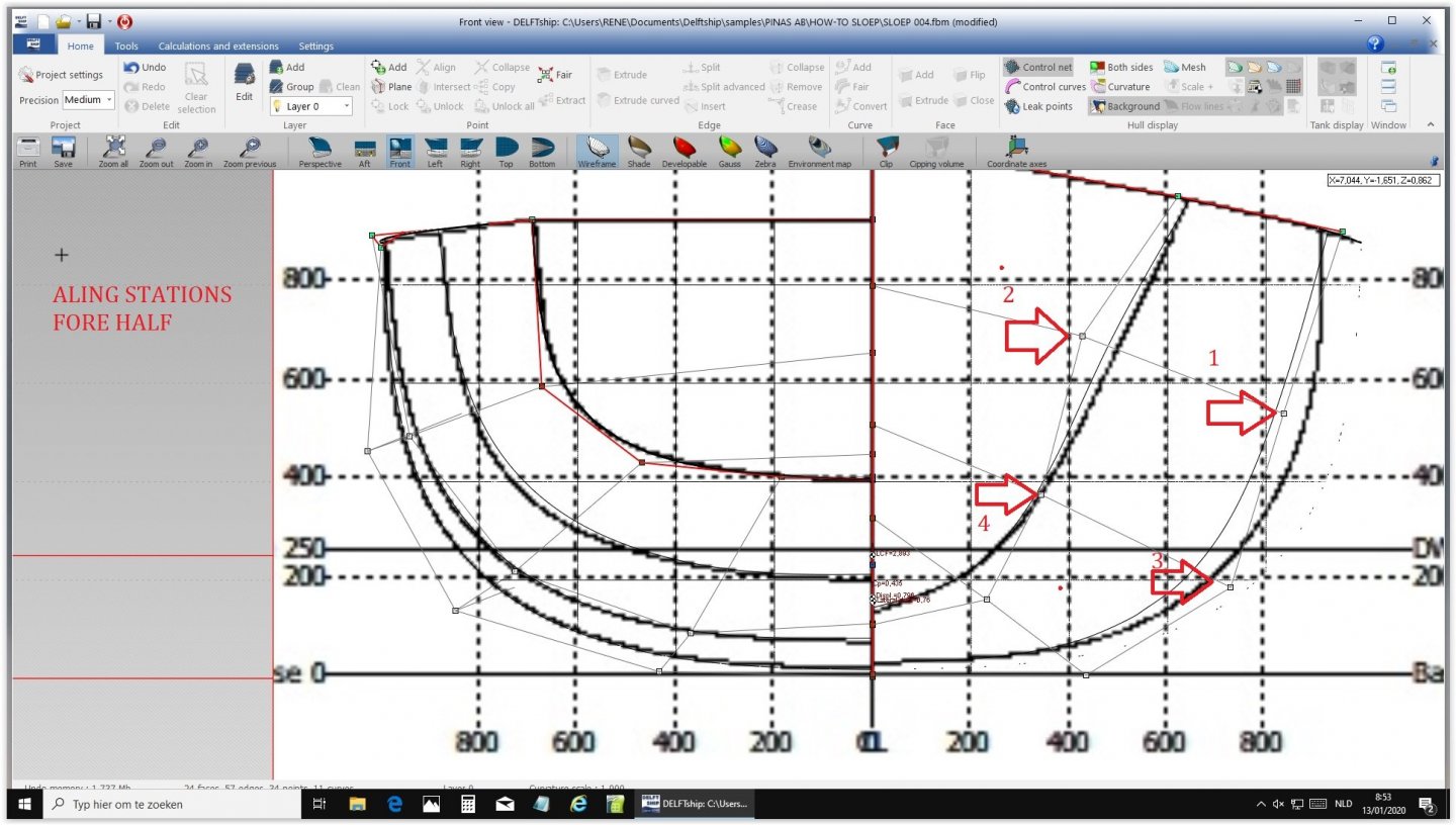
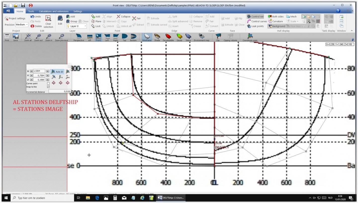
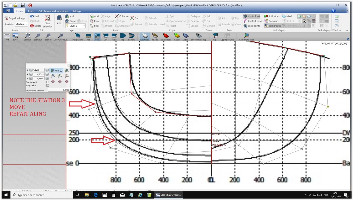
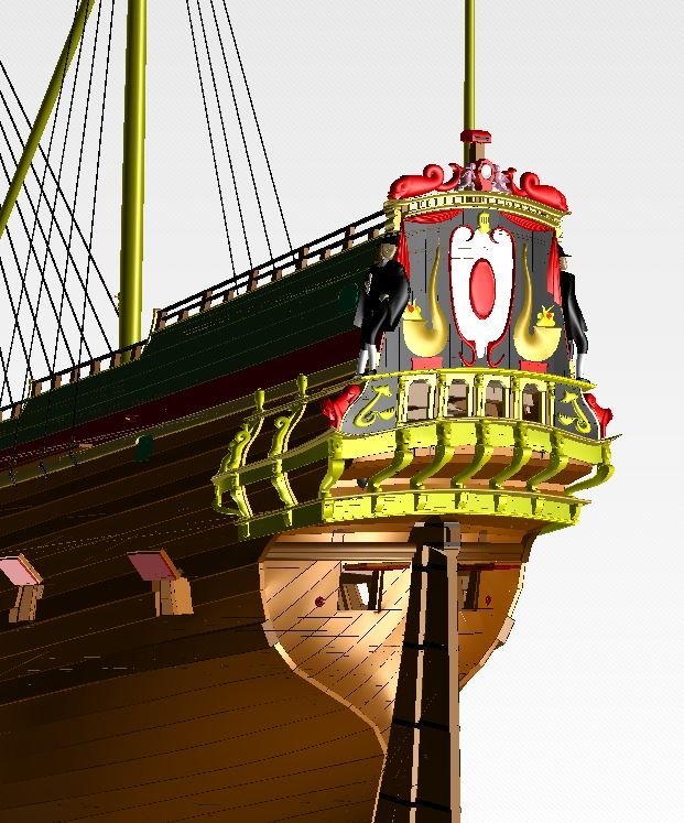
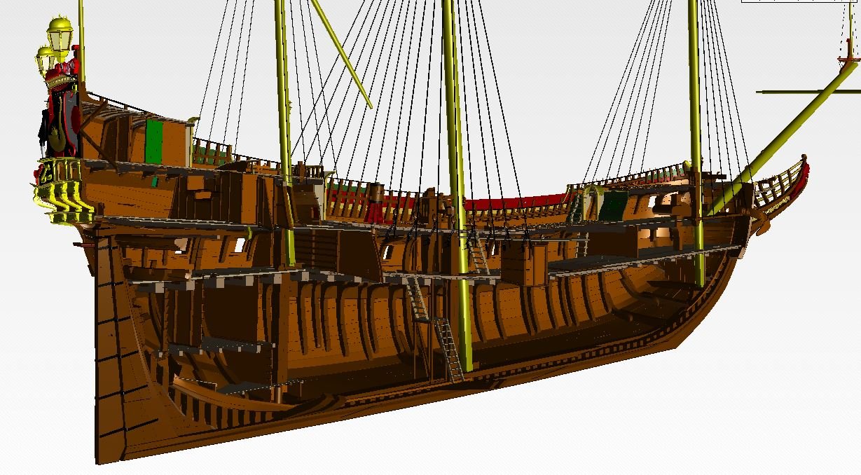
Import body plan. Choose Front Open edit background images Import body plan Match base and center line Alingn transom Match aft frames Align fore station lines repeat aft station lines, starting from the outside. Here is the new lines plan When we created the lines plan for the ship I showed on Januari 7 as an example of what Delftship was capable of, we worked solely from the specification contract in Witsen's book from 1671, so without a base lines plan. The contract specified eight frames with on every frame seven or eight positions. That was of course much more complicated than this example, but the program allows for such actions. Even with less stations DELFTship, being a ship design program, fairs the lines and completes the shape of the vessel. It takes a while to master it, but Rene even succeeded in shaping the carvings with this program: Also the entire interior of the ship was built, which allows other specialists to convert it into a program allowing visitors to explore the ship in and out. This will be published soon on an internet site, accessible for anyone who is interested. Thanks for your attention.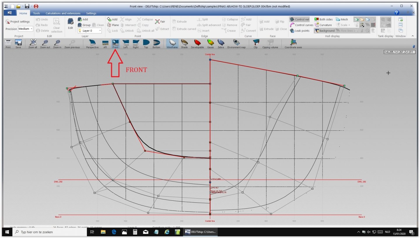


-
Need CAD type program
Ab Hoving replied to Sambini's topic in CAD and 3D Modelling/Drafting Plans with Software
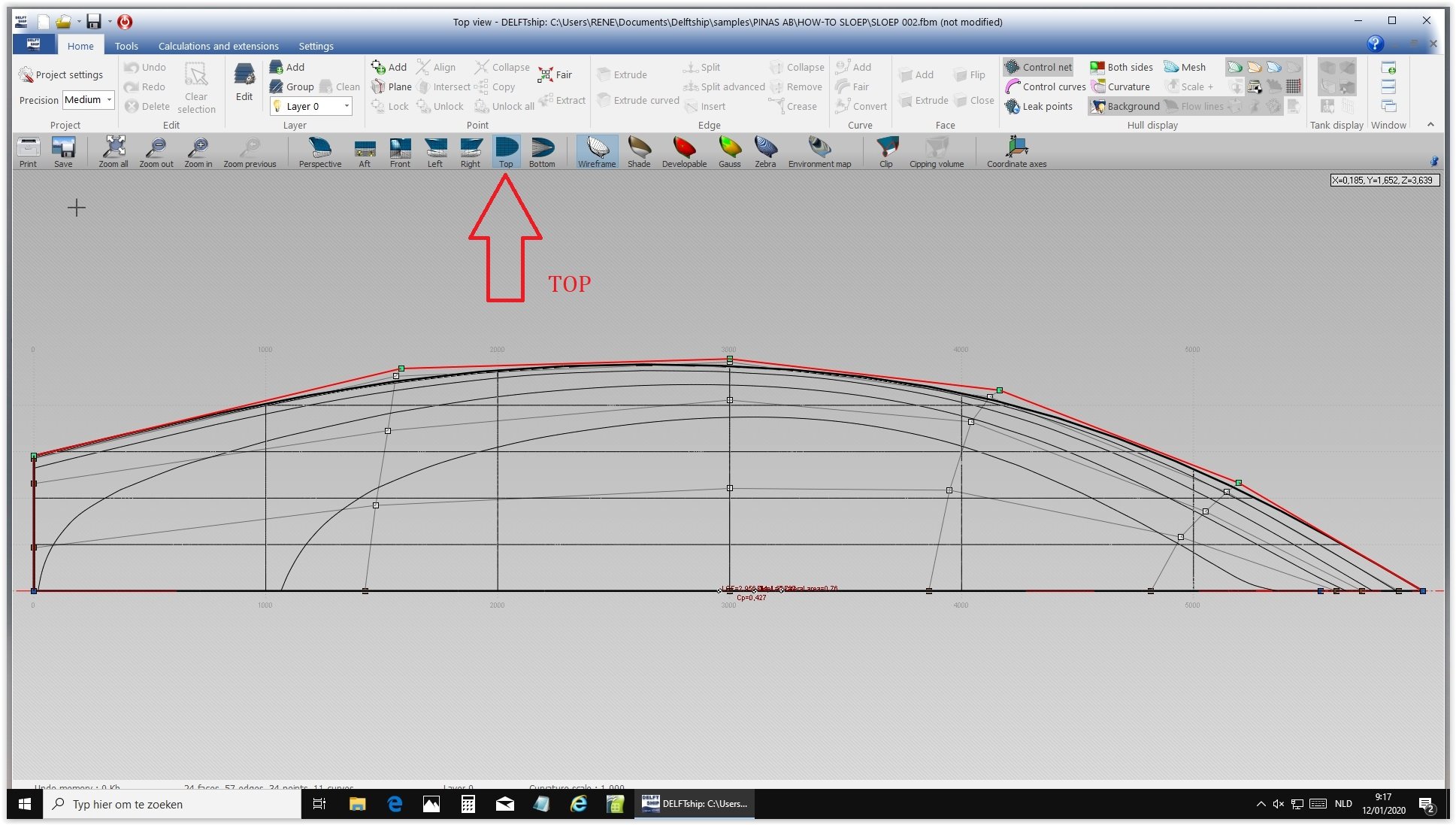
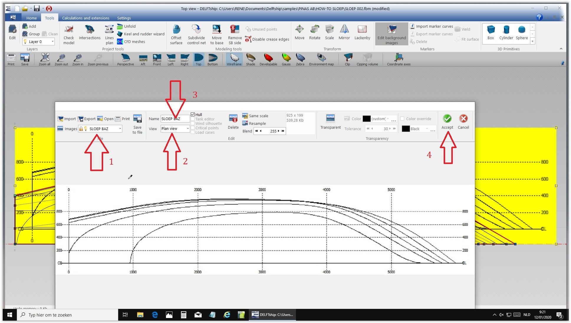
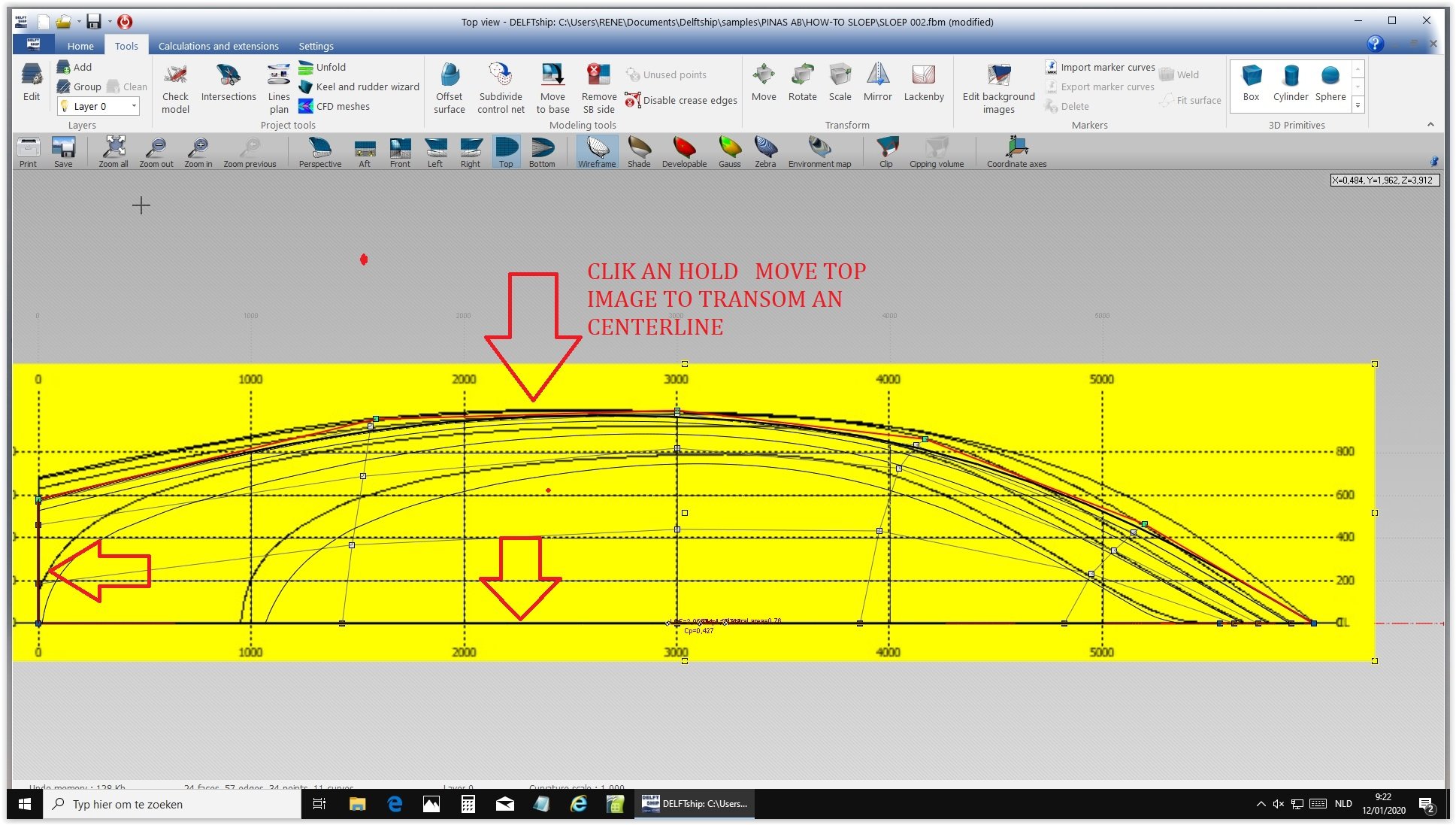
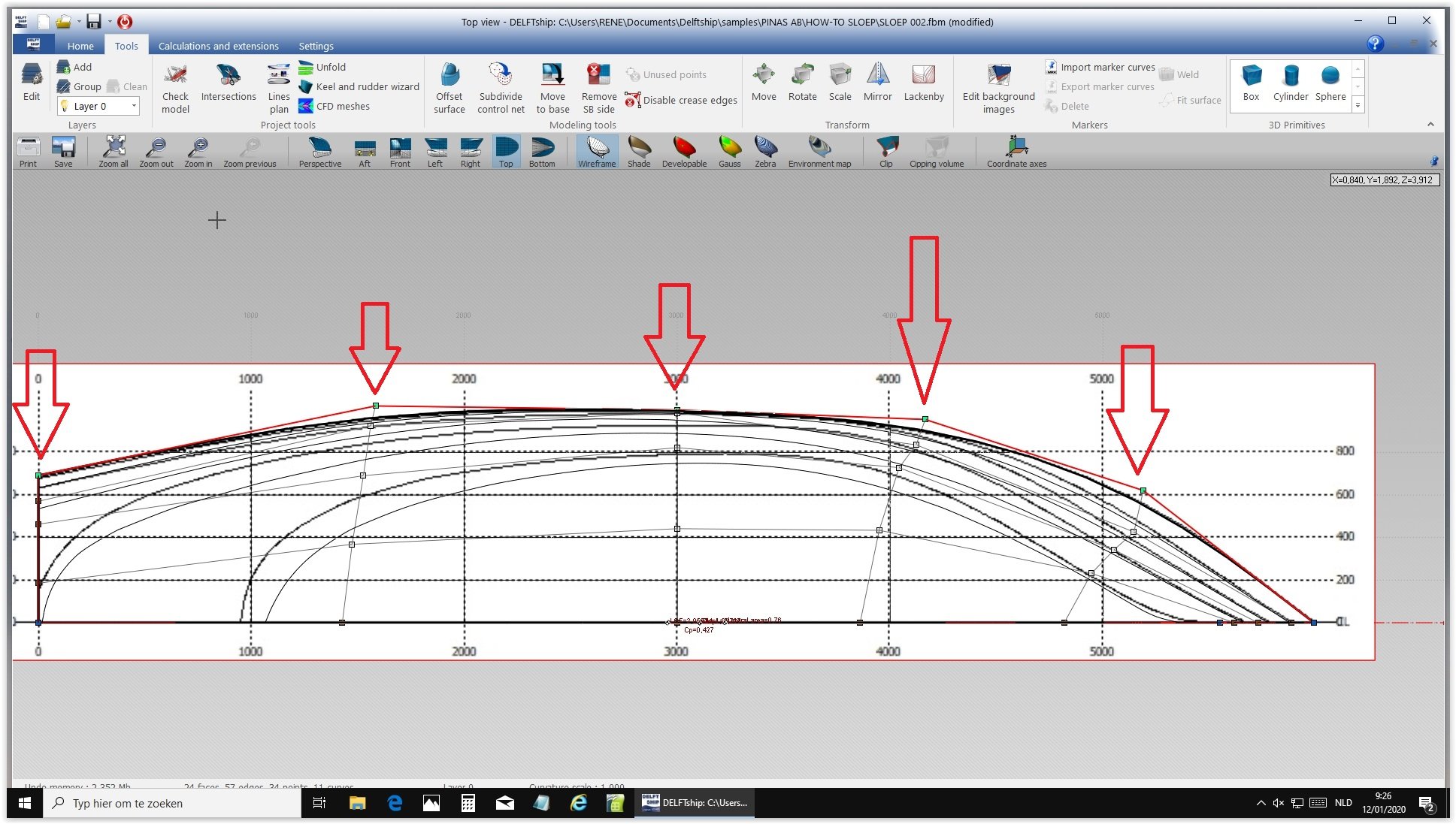
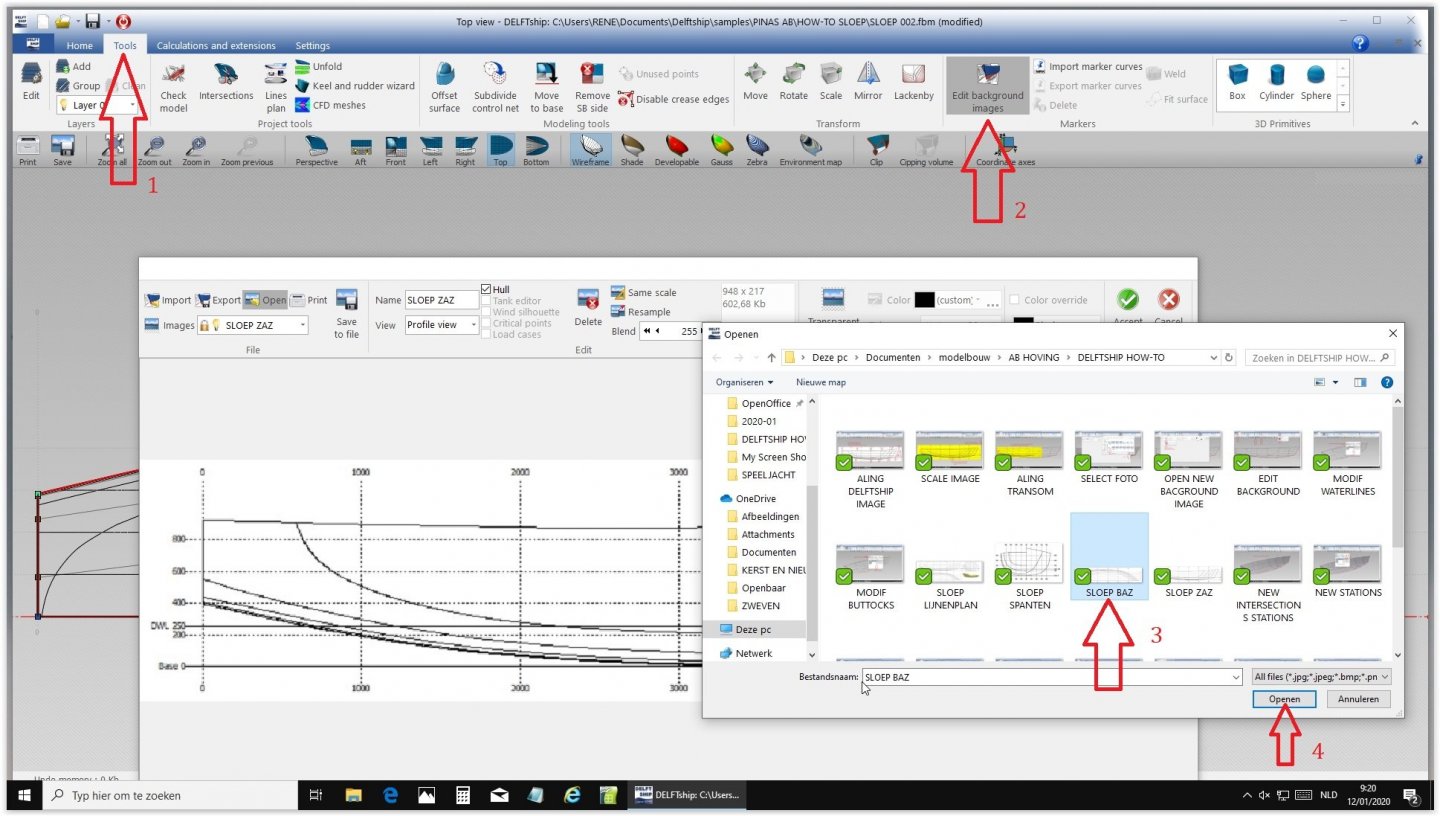
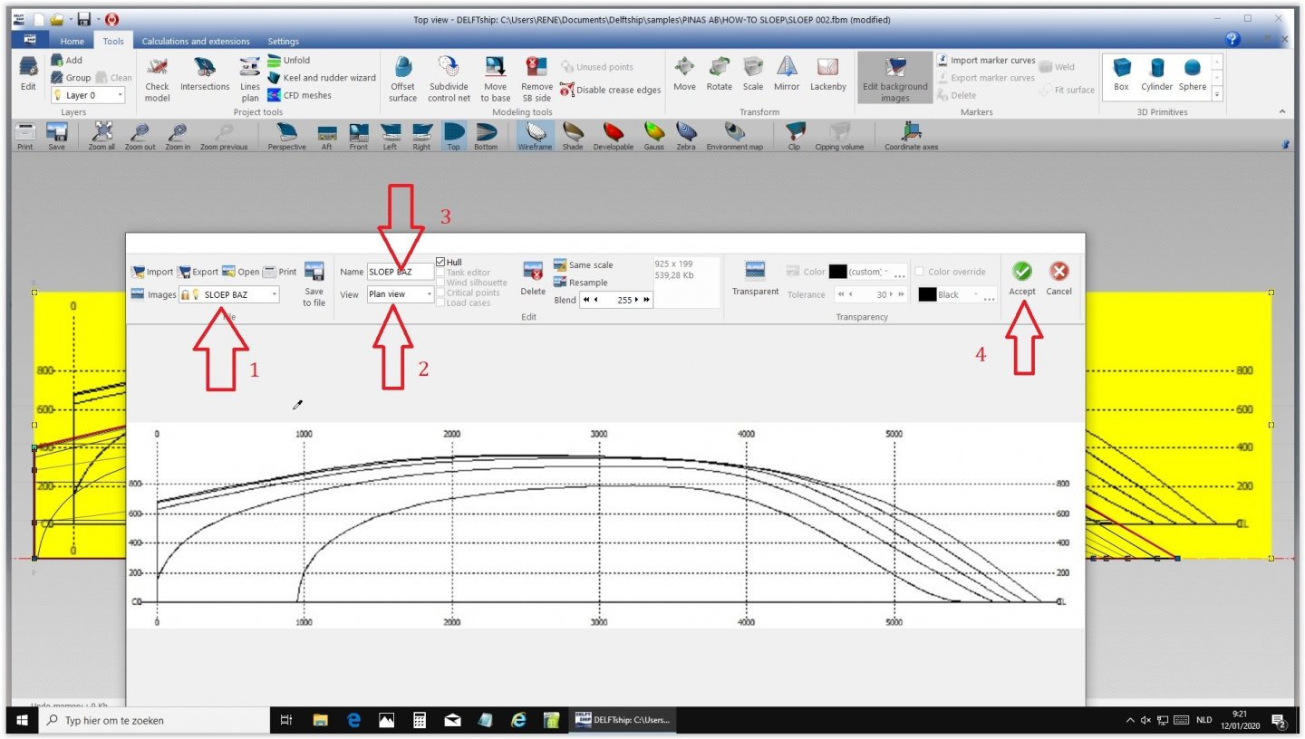
Here is how to insert the top view: Select 'top' in DELFTship. Then: 'edit background images'. Choose your top view and import it into DELFTship Click and hold top view and drag it until stern and centerline are equal to the DELFTship stern and centerline. Stretch it till they fit. Click and drag the DELFTship lines until they match with the new design, just like you did in the side view. Next time the body plan, but I think the system becomes clear now...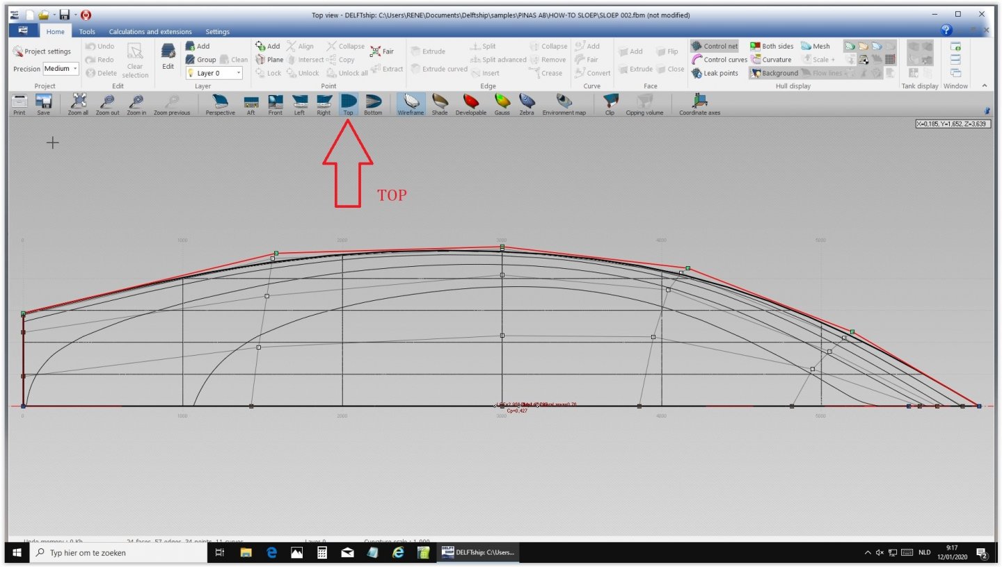


-
Need CAD type program
Ab Hoving replied to Sambini's topic in CAD and 3D Modelling/Drafting Plans with Software
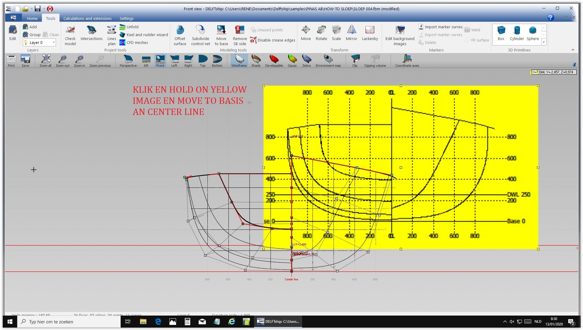
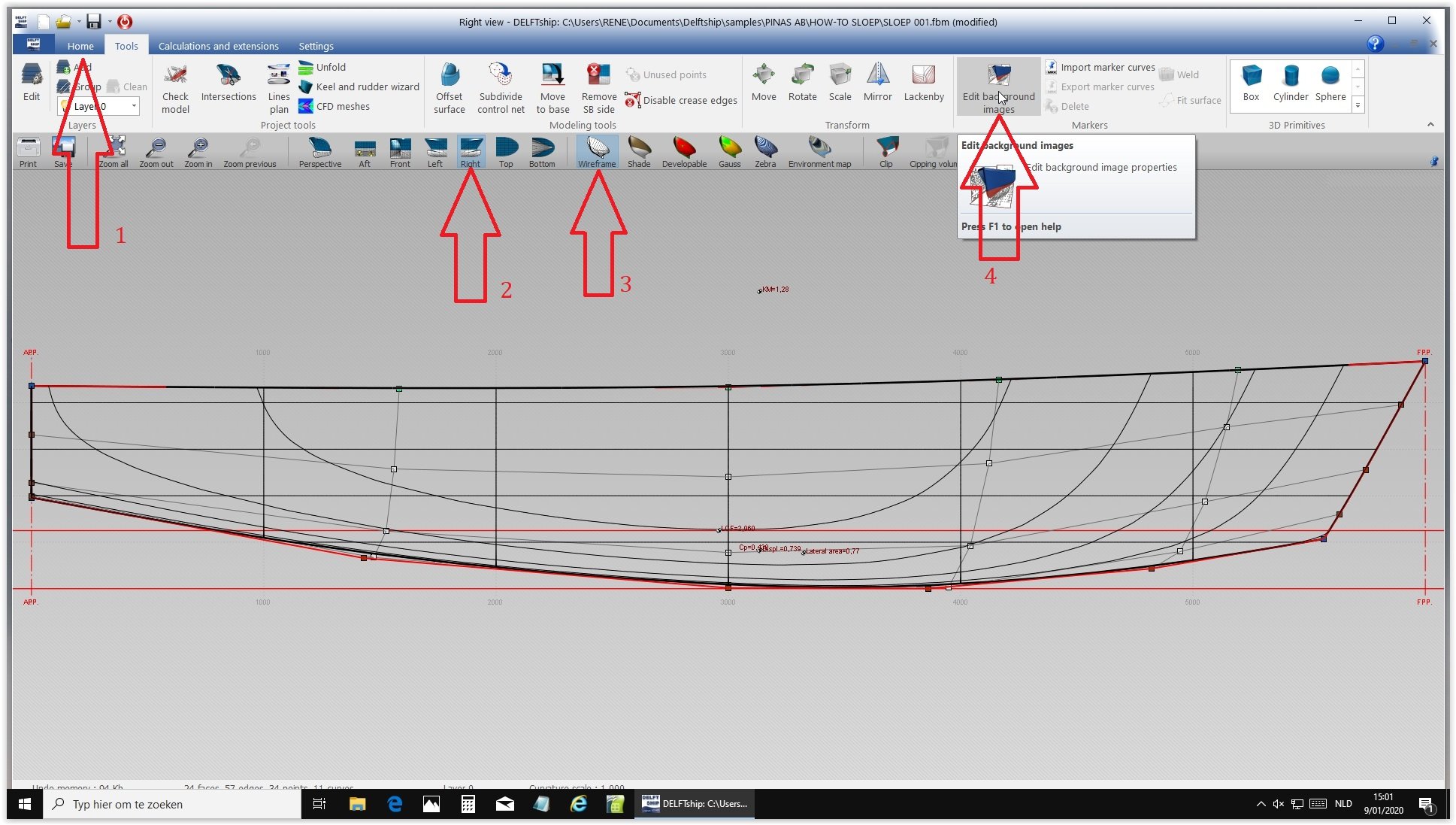
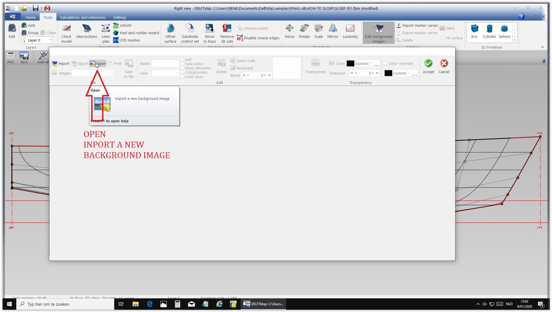
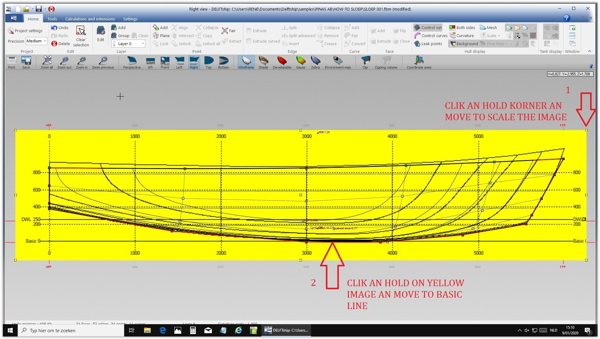
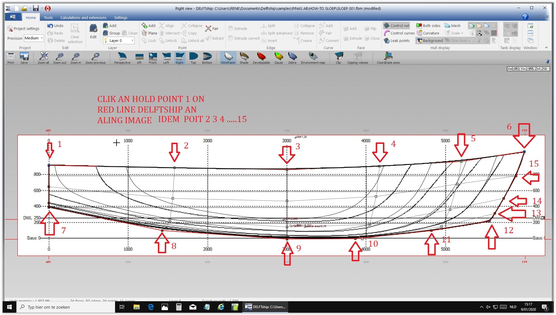
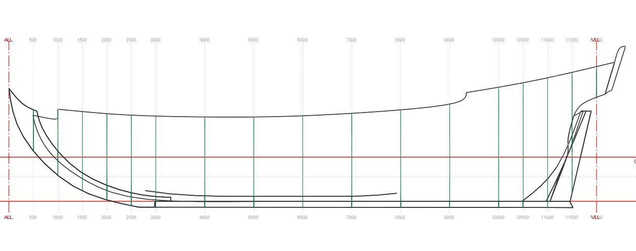
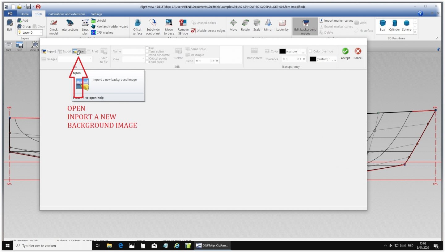
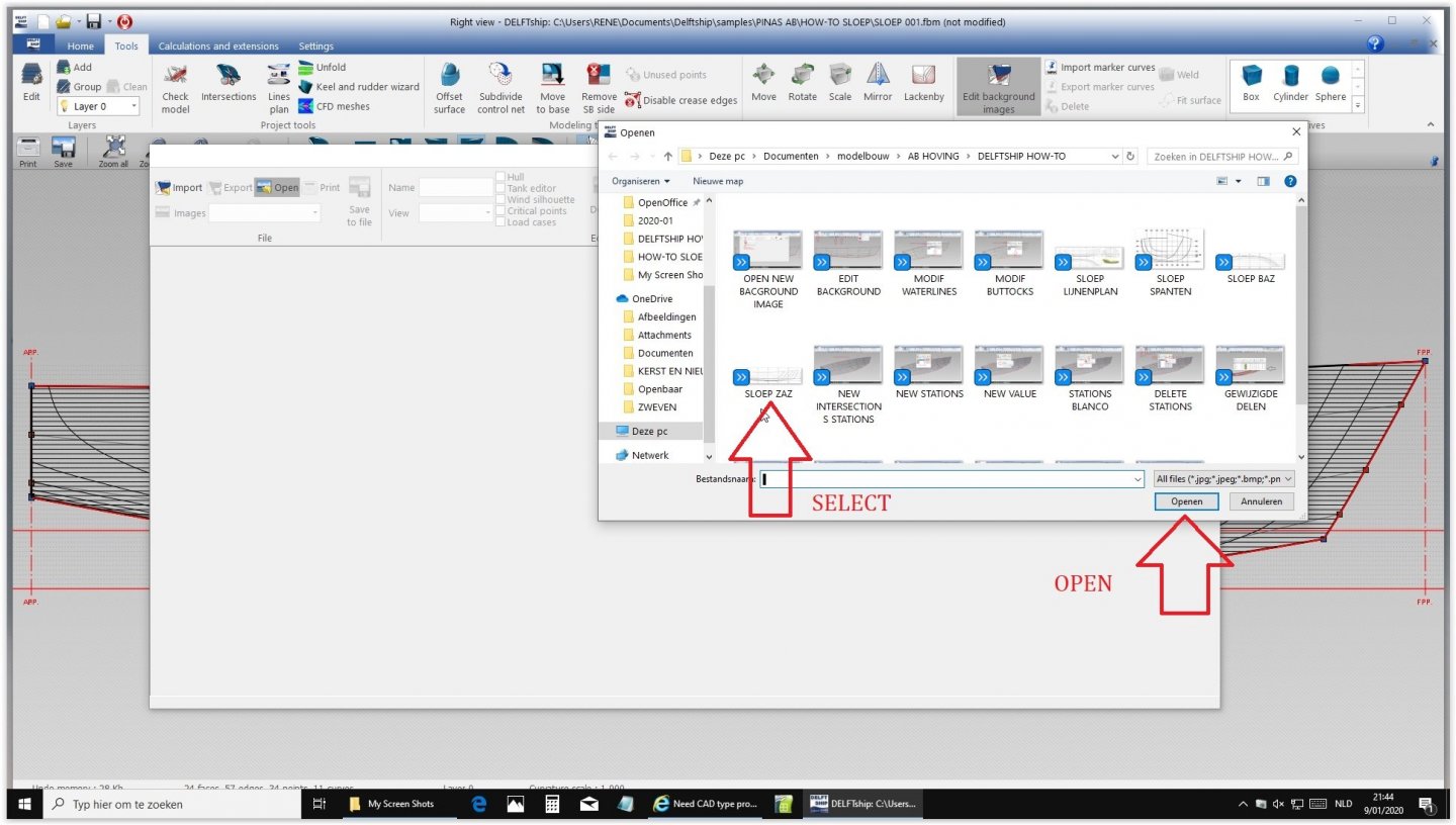
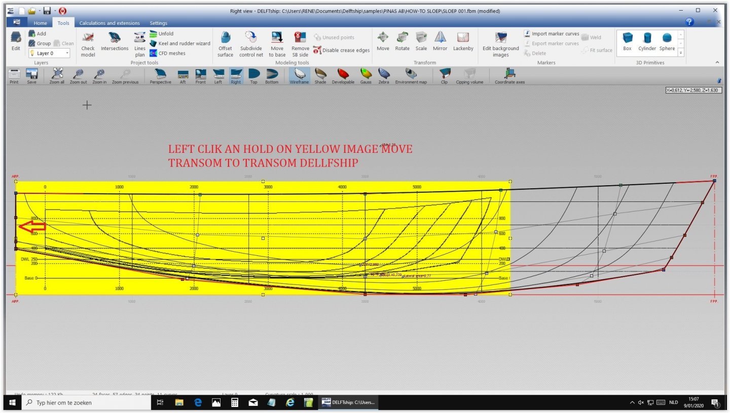
How to import the side view. Choose side view and edit background. Open import background image and select ZAZ and open. Click and hold to match the sterns Click and hold the right top of the yellow image and stretch until both hulls match. Check and double check. Do the same for the bottom until they match ate the bottom line. Click on the yellow part, which turns to white. Now click and hold several points on the DELFTship hull and drag them to the new shape until they match. Make sure that in the end the fat black lines match perfectly. This takes some experience. Now the outlines should be equal. Next time: same procedure in top view and body plan.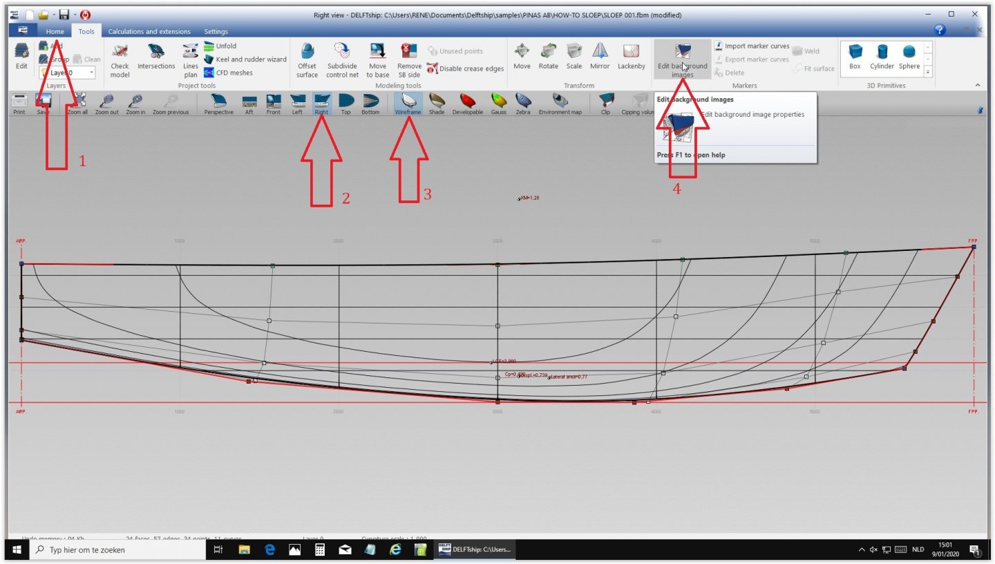


-
Marcus, Why do your four forward frames curve inwards at the top?