HOLIDAY DONATION DRIVE - SUPPORT MSW - DO YOUR PART TO KEEP THIS GREAT FORUM GOING! (89 donations so far out of 49,000 members - C'mon guys!)
×


Ab Hoving
-
Posts
691 -
Joined
-
Last visited
Content Type
Profiles
Forums
Gallery
Events
Everything posted by Ab Hoving
-
 The bowsprit might originally be used to serve for the bowlines (I suppose).
 -
Very nice thread. I like the research, knowing how hard it is to get trustworthy information. Making changes to a model under construction is only proof for a serious attitude towards historical reality.
-
I like this project very much. Great research, nice building, amazing result. Congratulations.
-
Maybe I can shed some light on this. The book 'The ships of Abel Tasman' contains two draughts, one of the yacht Heemskerck and the other of the fluit Zeehaen. The book deals with the process of designing these two reconstructions and tells the story of Abel Tasman's travels in 1642. Published by Verloren. https://verloren.nl/boeken/2086/253/168/maritiem-en-waterstaat/the-ships-of-abel-tasman The book '17th century Dutch Merchant ships' contains the draughts of many characteristic vessels of the Dutch merchant fleet, amongst which several fluits. One of them is the Zeehaen. Published by SeaWatchBooks: https://www.seawatchbooks.com/ItemDisplay.php?sku=114003 I hope this helps. Good luck, Ab
-
Easy. Look here, page 4:
-
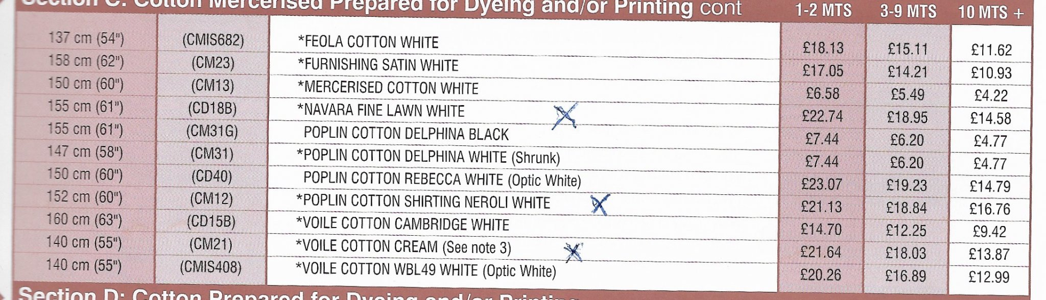
If you are looking for material for sails this address may be the solution for your you: Whaleys (Bradford) located at Harris Court, Great Horton, Bradford, West Yorkshire, BD7 4EQ in England. E-mailaddress: info@whaleysltd.co.uk. For my purposes the best material to work with appeared to be 'voile cotton', but also 'Navara Fine Lawn White' works splendidly for my 1/77 scale. For the bigger scales there is also 'Poplin cotton shirting neroli white'. Prices are here. The material can very well be treated with starch and dried as wanted with a hair-dryer: Good luck, Ab

-
A former colleague at the Rijksmuseum, Susan Meyer, suggested i should use 'voile cotton' for sails and she gave me a piece, which I used for this ship, with the result shown here-fore. She also mentioned the name of an English company which was most helpful in finding the right material after a sample of the wanted textile was sent to them. It is a remarkable company, called Whaleys (Bradford) located at Harris Court, Great Horton, Bradford, West Yorkshire, BD7 4EQ in England. I sent them a sample of the very fine cotton I used until my stock (which existed of a sort of textile, I removed from old maps, soaked in water) was gone and I had to find a replacement. Today I received an answer with several samples of cloth that were very close. Indeed, like my colleague suggested 'voile cotton' was one of them, but there was another, called 'Navara fine lawn white', which seems even slightly better. It is slightly less transparent and very closely woven. It costs 22,74 pound per meter (1.55 m wide) and if more than 2 meters are purchased the price is 18,95 pound. 'Voile cotton cream' is slightly cheaper but comes with a width of 1.40 m. I supposed some of you just wanted to know.
-
More enthusiasm than I anticipated, thank you very much. It's just pottery, little more. Wefalck: the scale is 1/77 and the sails were simply sprayed with a spray can of starch your mother probably used while ironing the sheets. Her hairdryer did the rest (together with some pushing and pulling of course). 'Hans' We can discuss some ins and outs for the kits you sell, if you like. GrandpaPhil: Your own efforts with paper are not too bad either... Druxey: I'm flattered being told that by you. You are not particularly from the easy approach like I demonstrate here. Petr: Thanks, but in your country there are so many better builders, you included. Marcus: I missed your recent updates about planking the fluit. Problems?
-
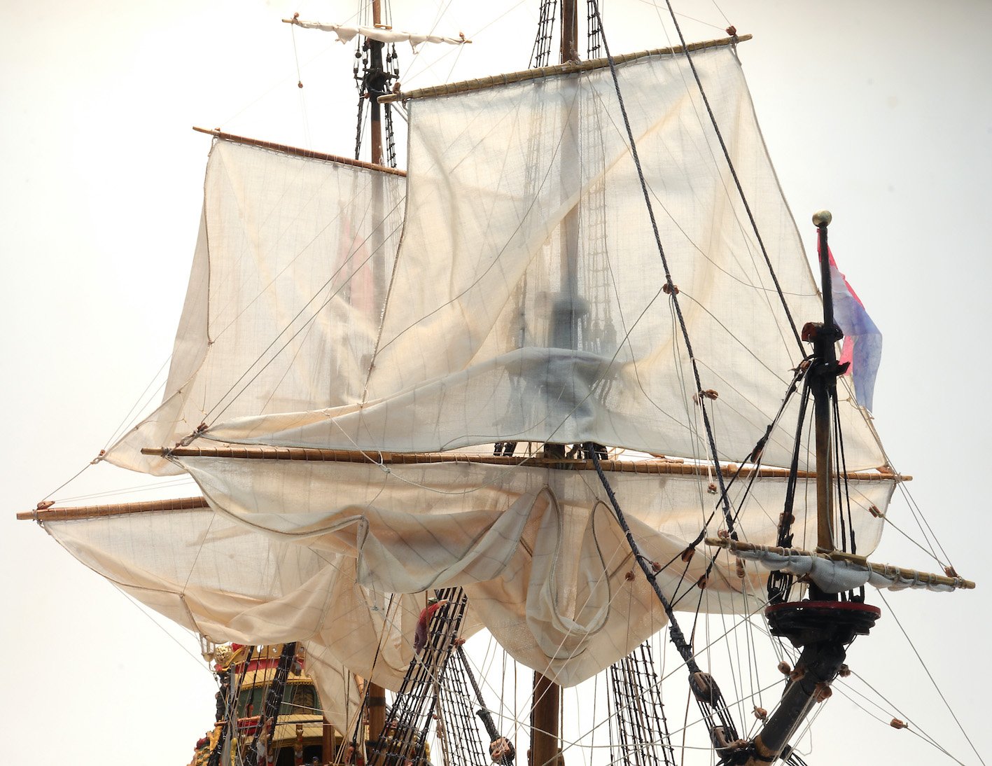
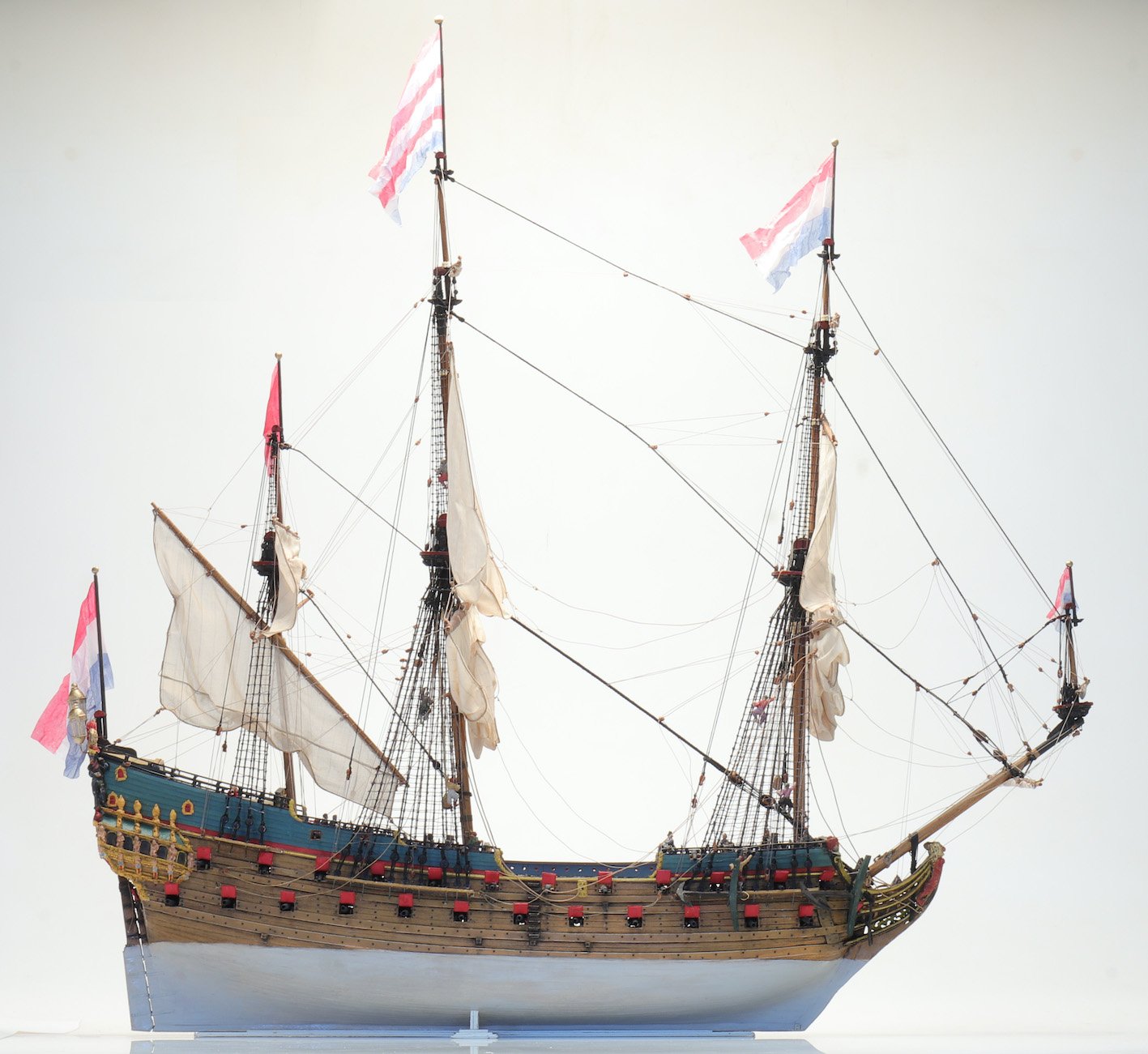
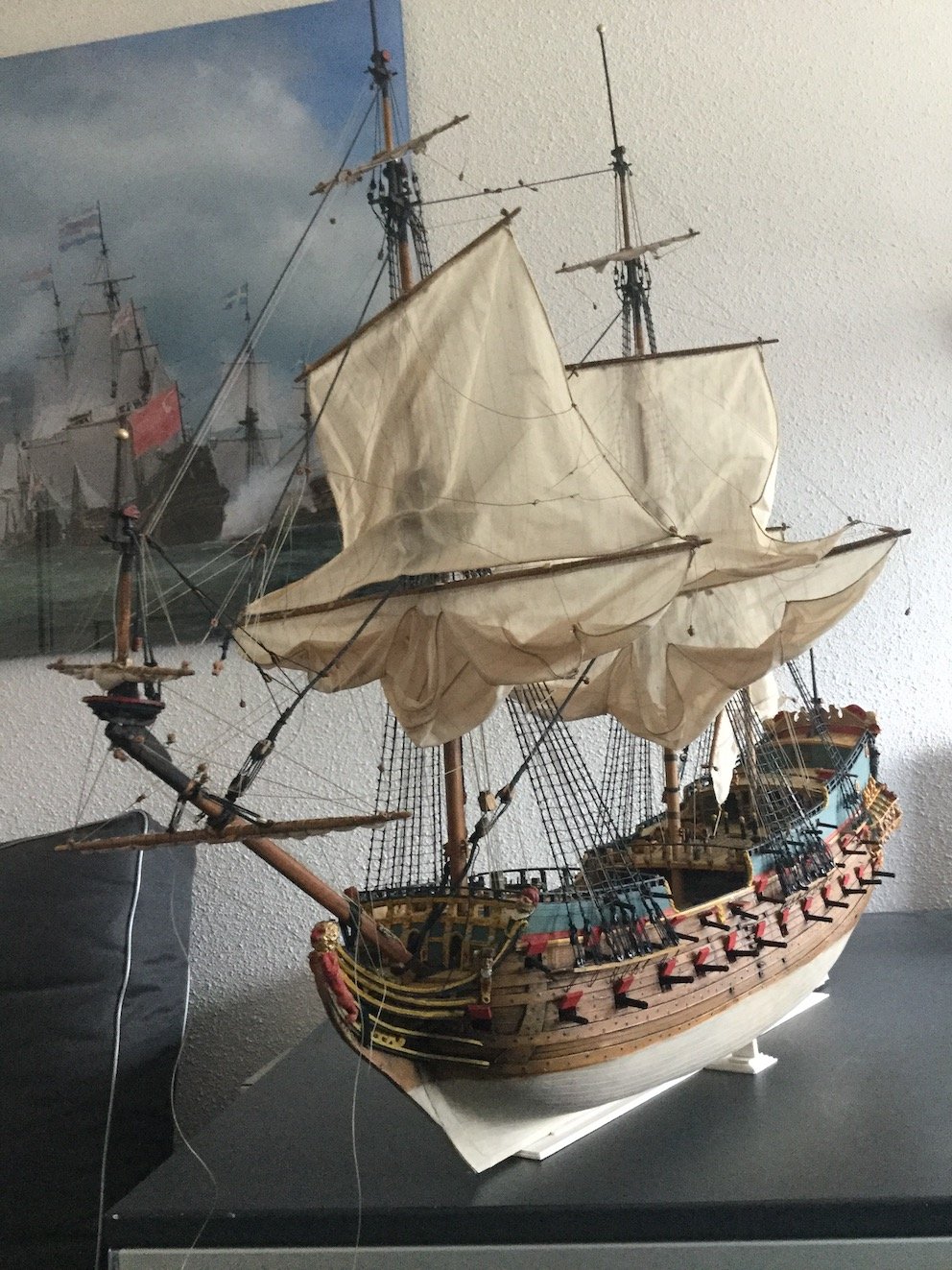
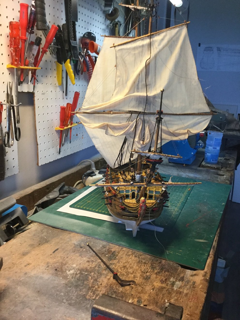
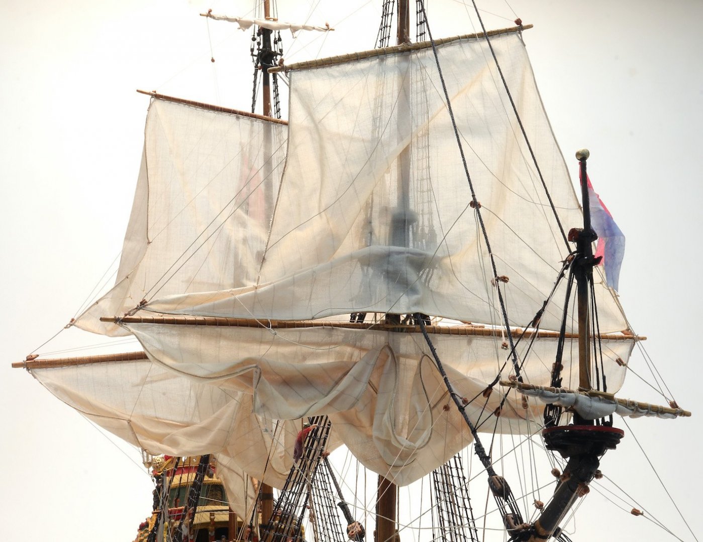
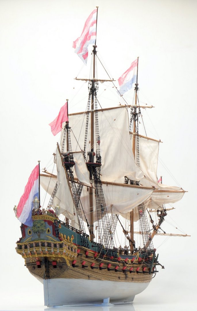
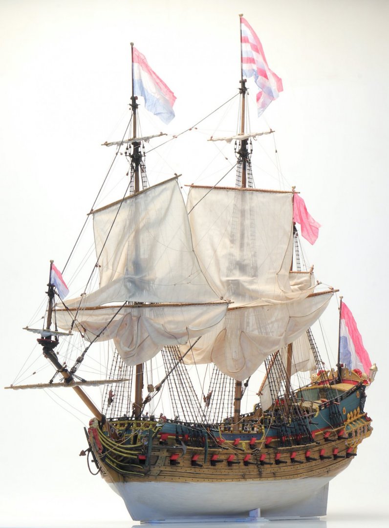
Just a note that I finished the man-of-war. These are the results: Not very spectacular from the side view. The quarter views are OK though. And the sails look like sails. I'm a happy man. Ab


-
Need CAD type program
Ab Hoving replied to Sambini's topic in CAD and 3D Modelling/Drafting Plans with Software
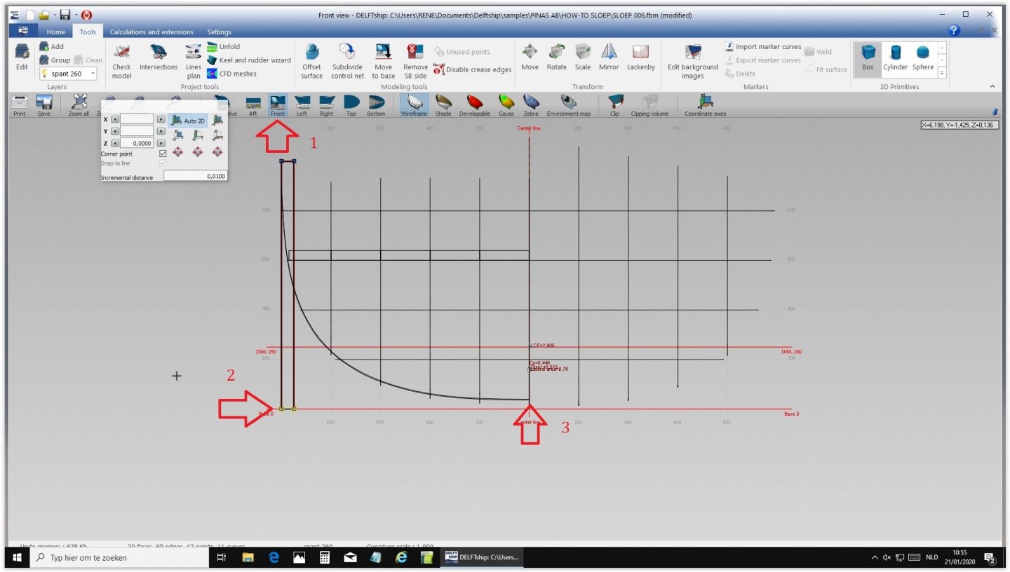
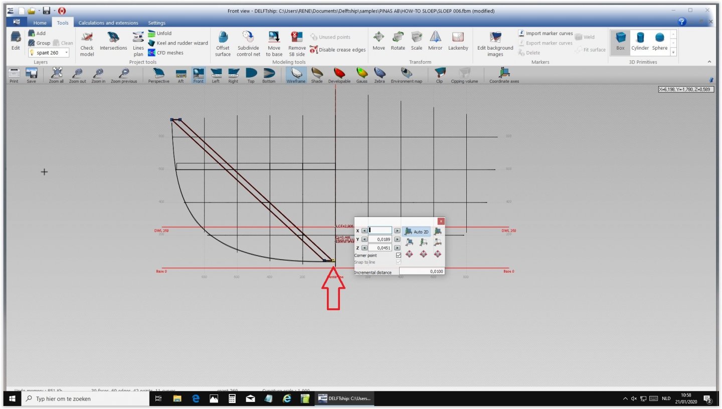
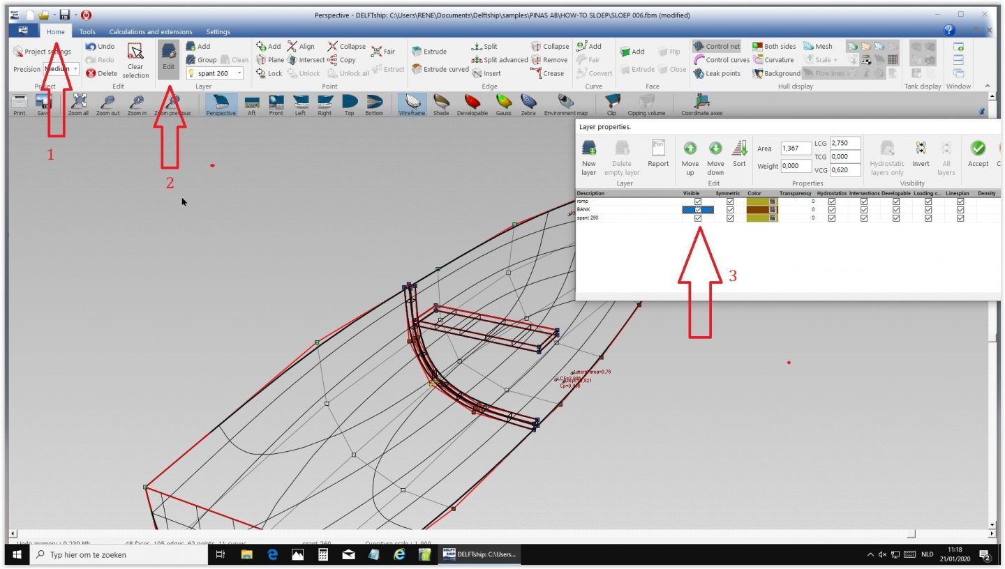
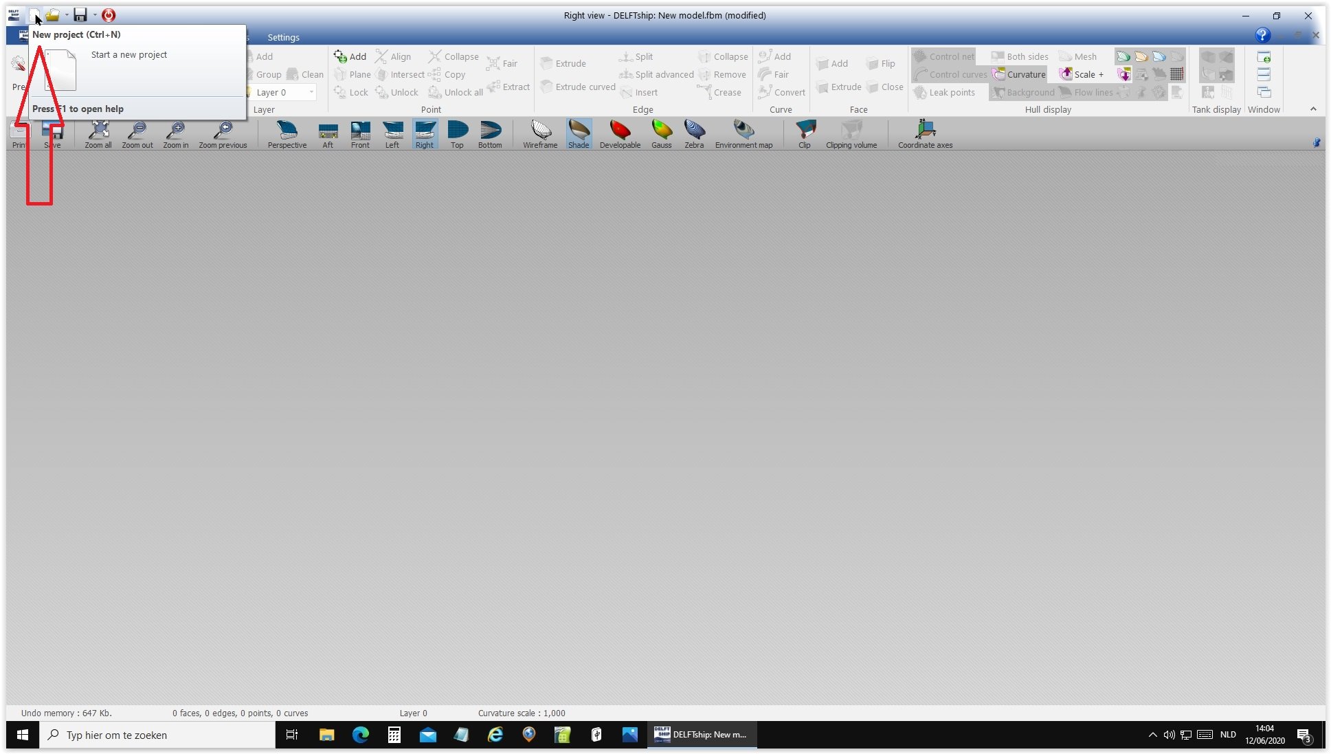
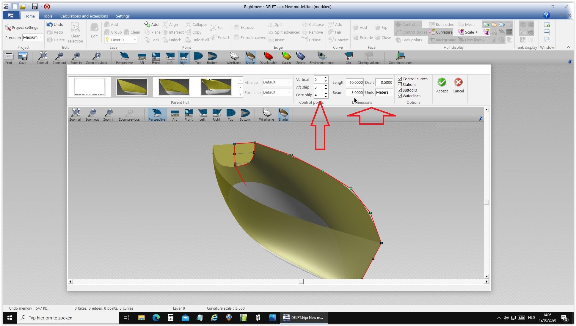
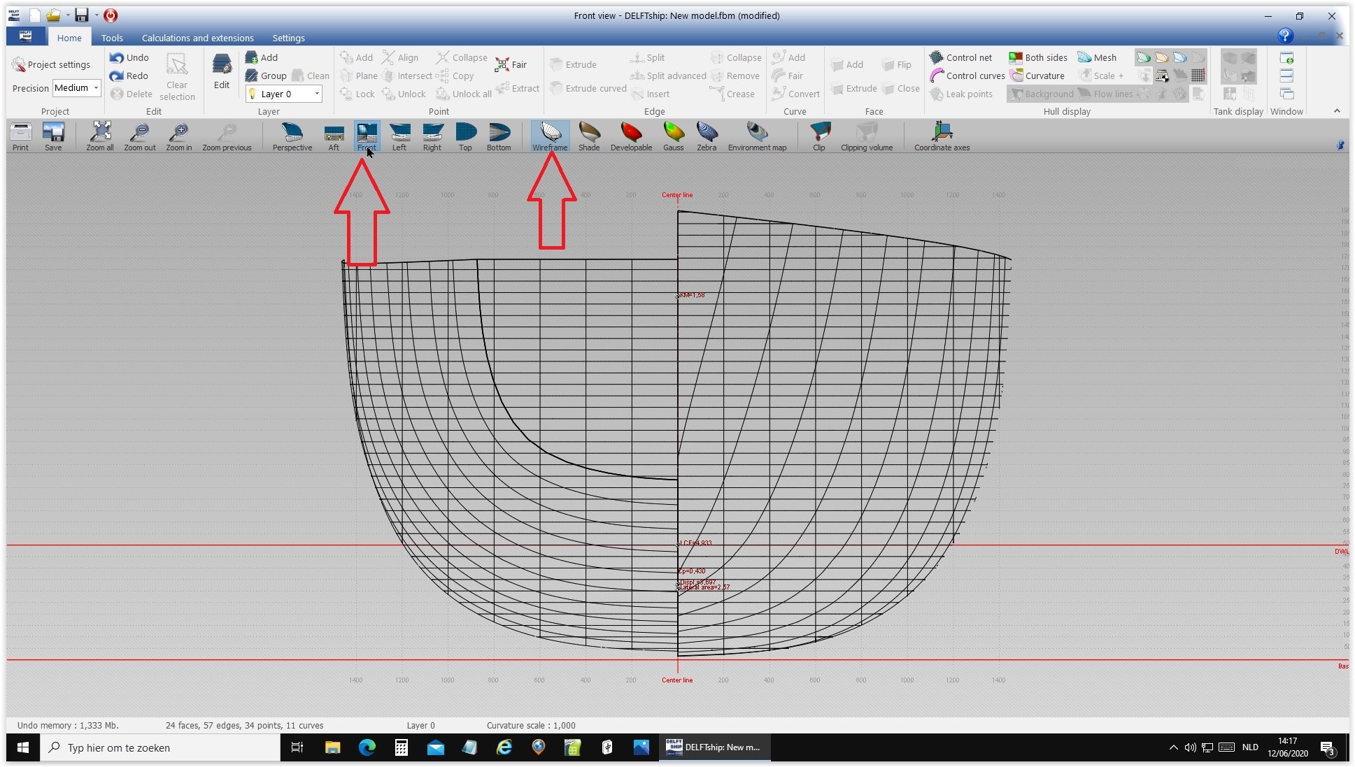
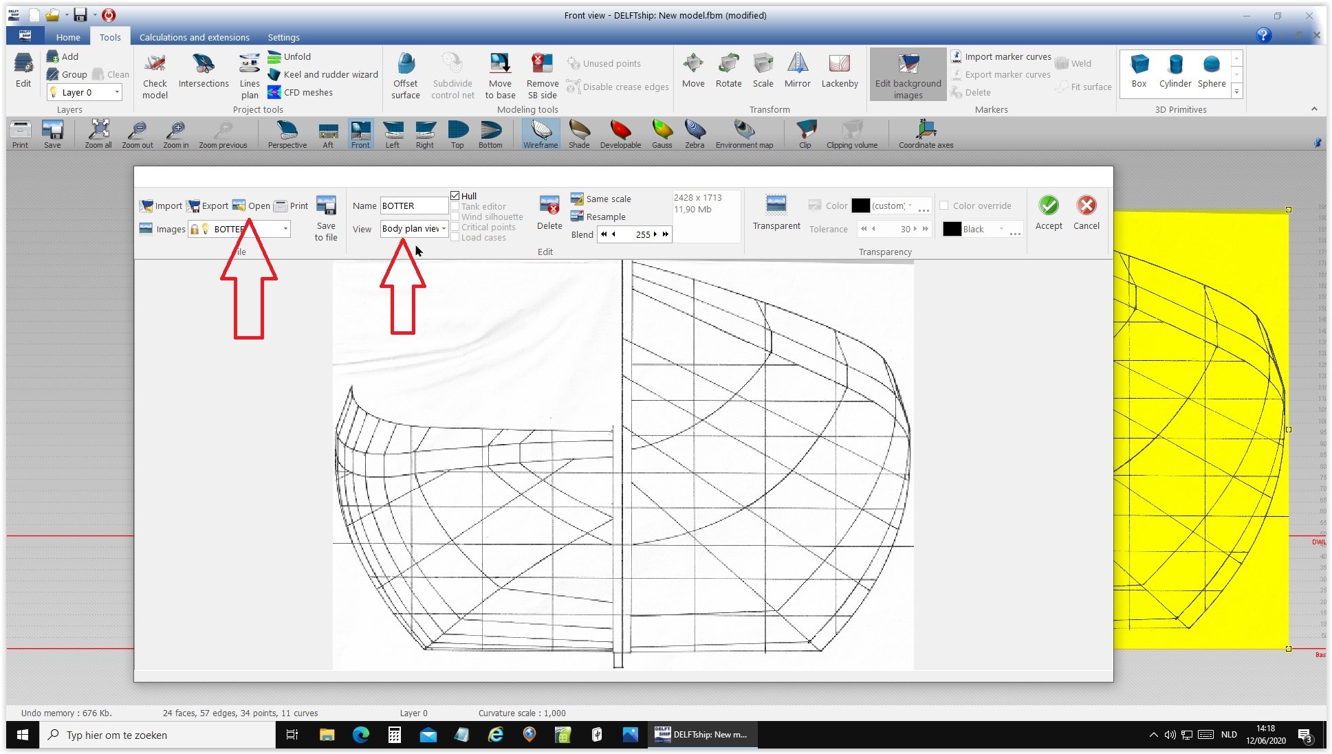
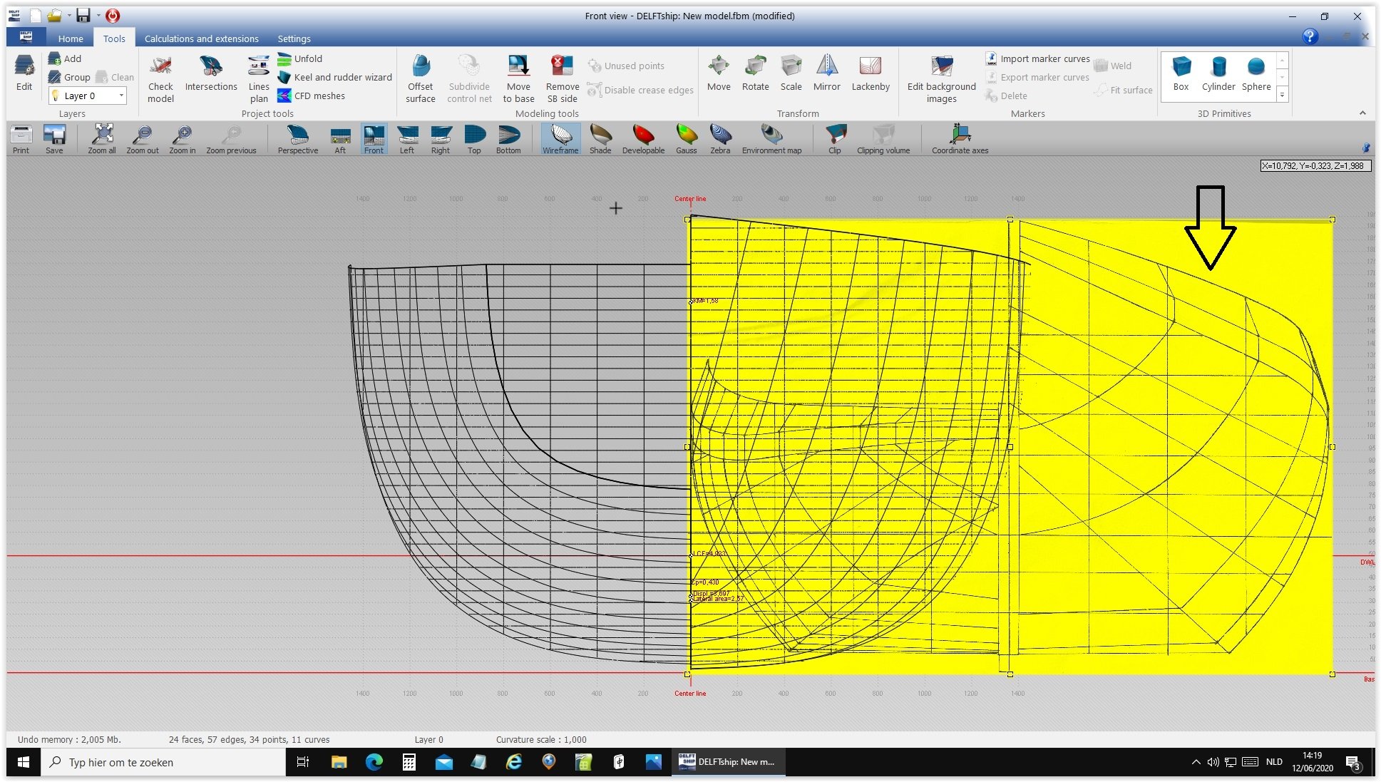
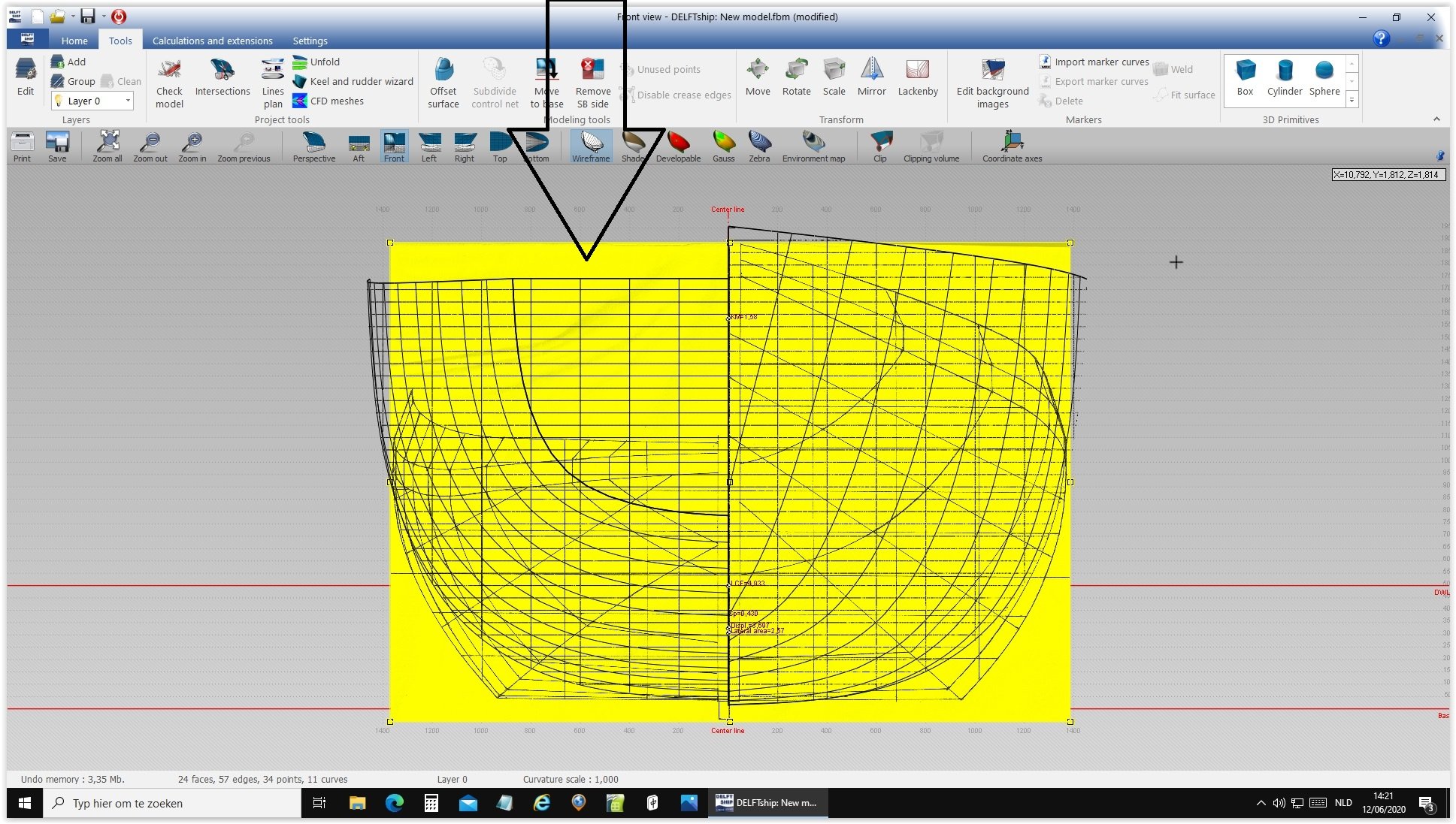
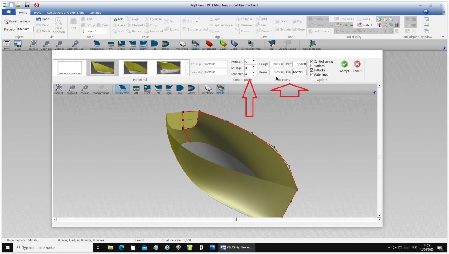
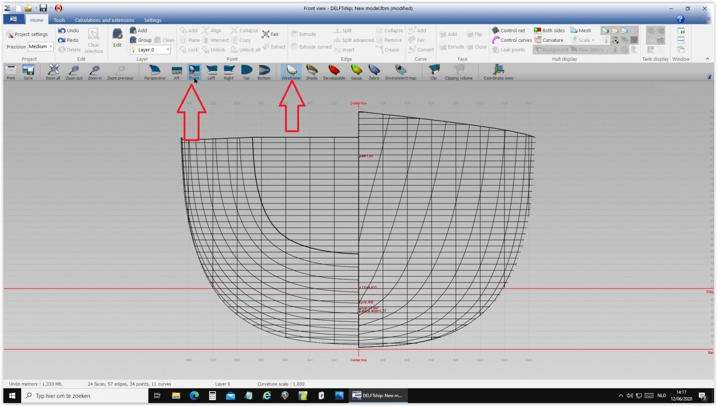
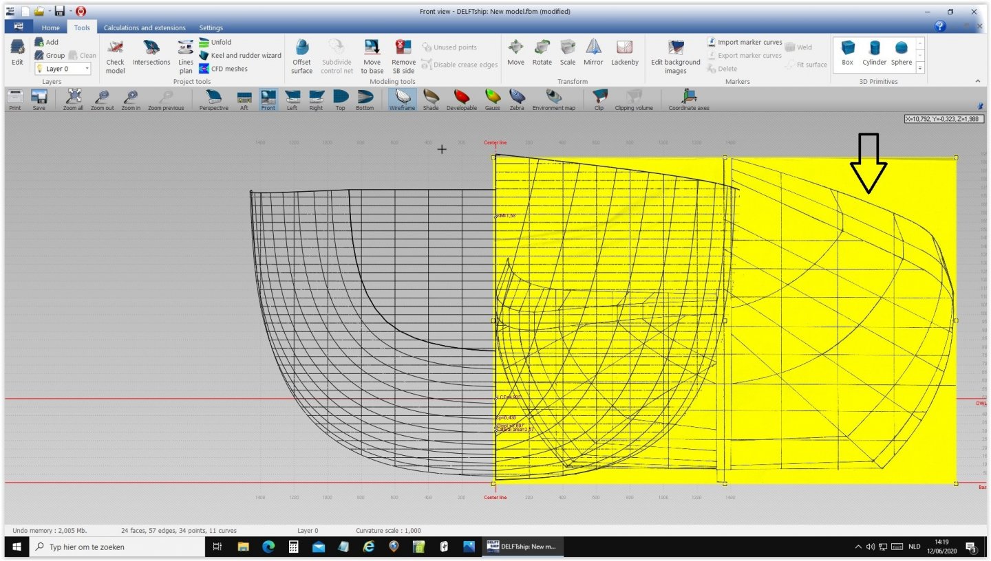
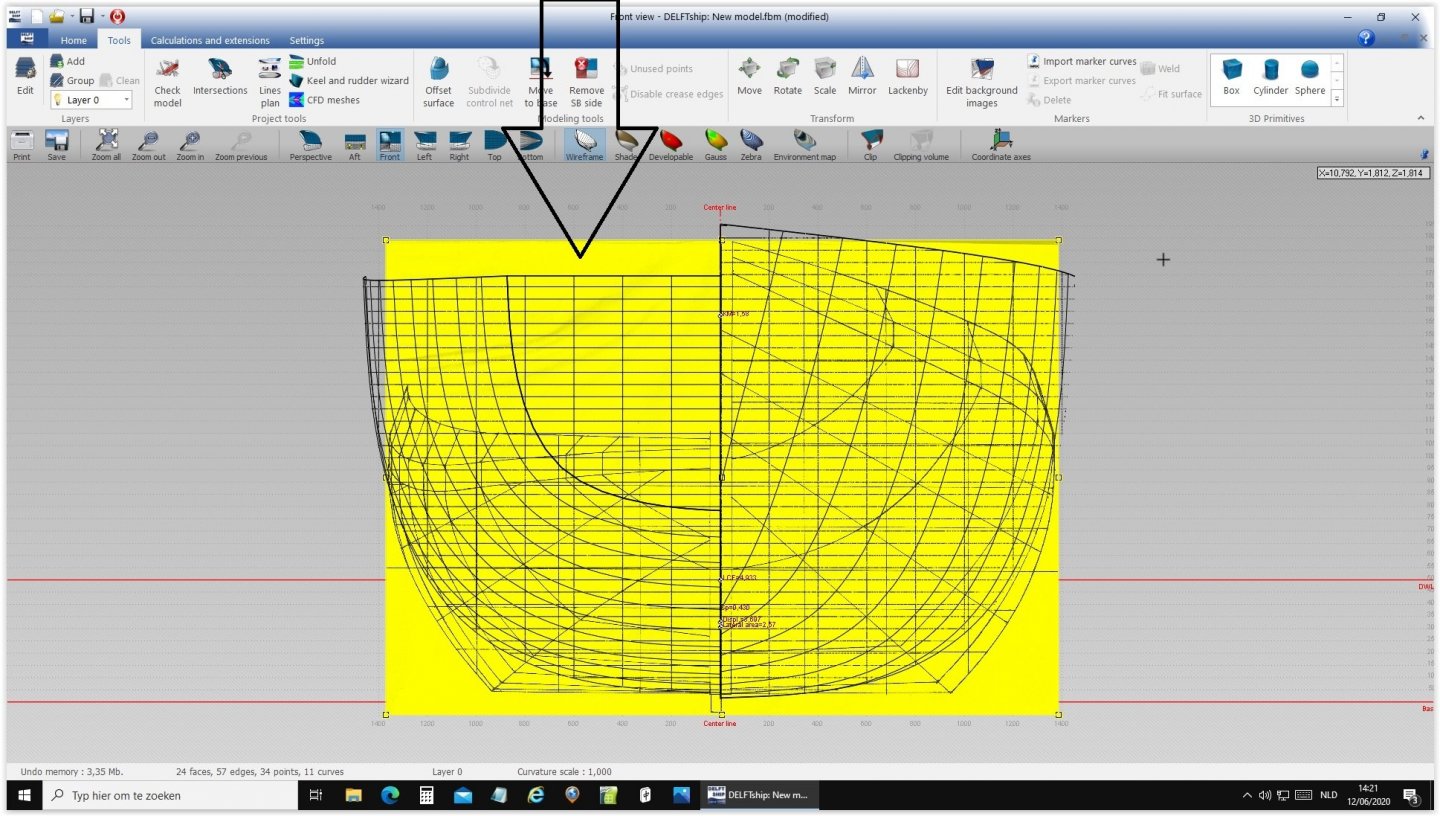
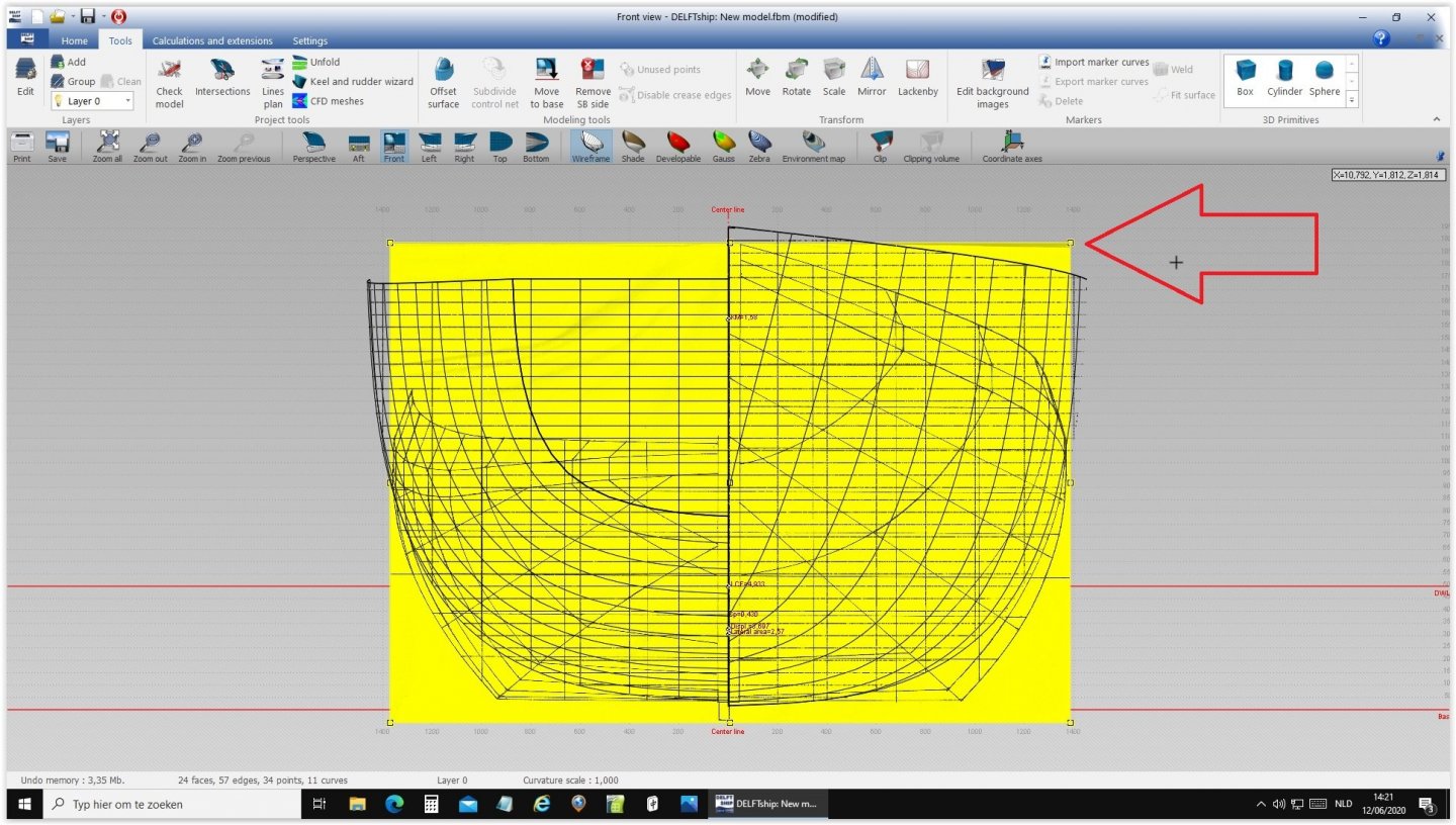
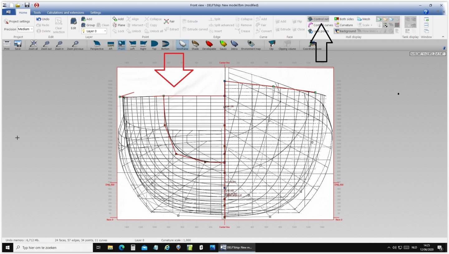
OK Bruce, here it comes: Start a new project Insert measurements and control point. Choose front view wireframe Open body plans and find your chosen draught Click to select your draught to become yellow. Click and drag the draught to the centerline and base line. Click and drag the top right corner of the draught for the right dimensions. Click and repeat the last step until a perfect fit it reached Click on image red arrow and control net black arrow. Now you can drag the control net points until the frames of both drawings are identical. This takes some exercise. Extra example hulls can be downloaded from the Delftship site, where they are selected by ship type. Hope this helps, good luck from Rene. Ab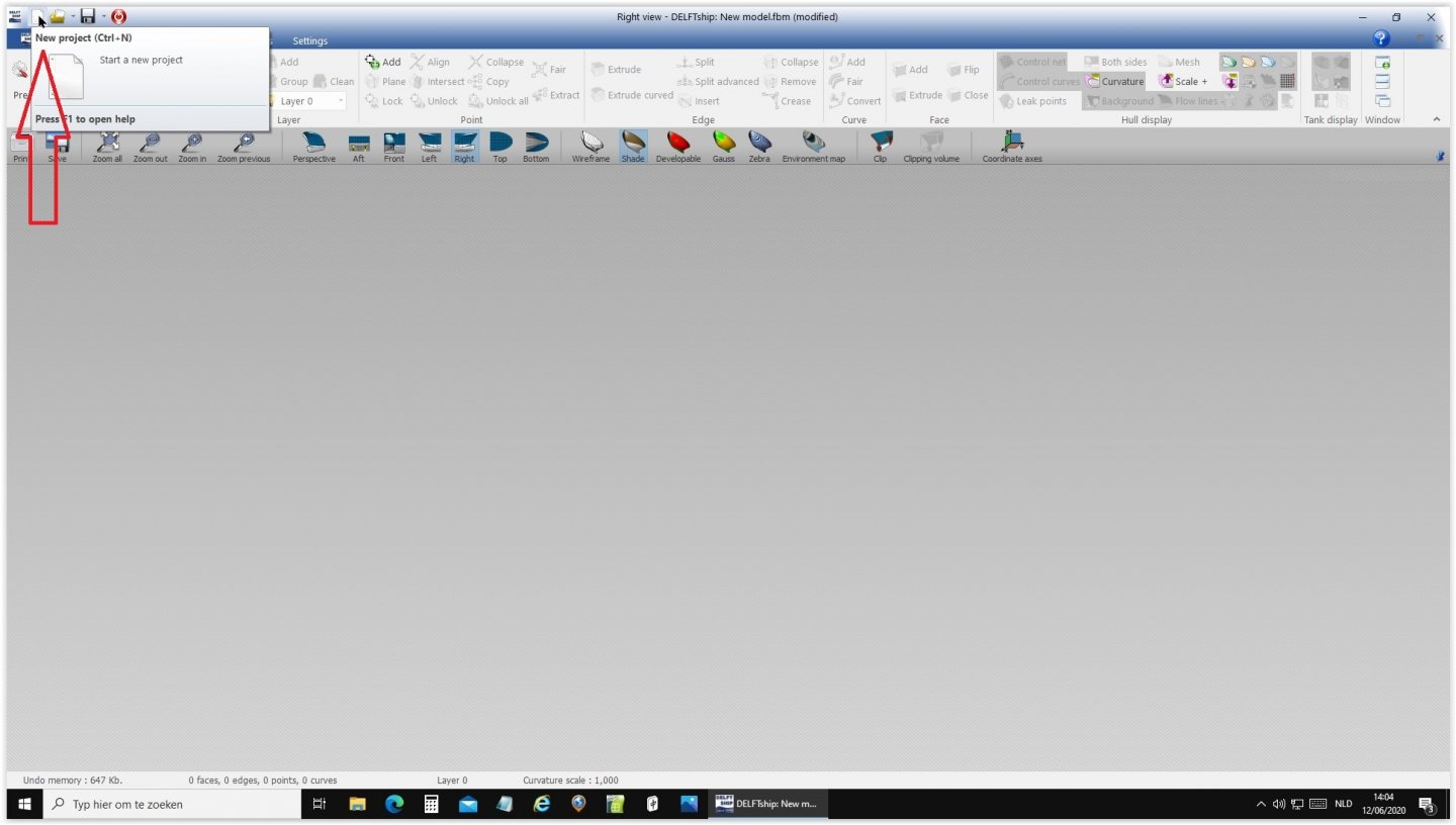

-
Need CAD type program
Ab Hoving replied to Sambini's topic in CAD and 3D Modelling/Drafting Plans with Software
Patience Bruce, Rene is preparing another tutorial. Ab -
To add sails or not? What is your preference?
Ab Hoving replied to Bill97's topic in Masting, rigging and sails
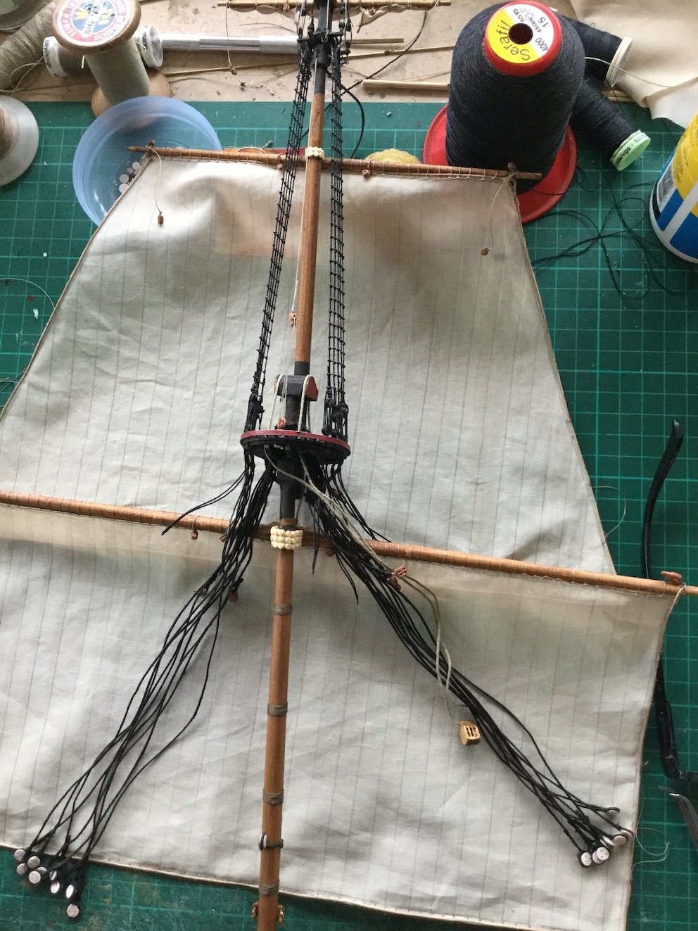
Just my 50 cents.... I like sails on models. They add expression and function. But if it is done, it has to be done well, as several of the shown examples clearly demonstrate. Too many people make yards without sails hoisted to the tops of the topmasts. I hate that. No sailor will ever take the trouble of hoisting an empty yard. Still, if a museum ship like the Constitution is modelled, or a navy board model is done, the absence of sails is right and logical. I always make sails on my models, furled or not. But if added, to my opinion they should express the conditions under which they are used. Therefore the choice of sailcloth is vital. After many efforts with various sorts of unbleached cotton I came to a fabric called 'voile cotton'. Almost transparent, but it can be colored well and if applied with a spray can of starch and a hairdryer, the result can be quite satisfying: I usually prepare my masts separated from the model as long as possible to save my poor back. Once the sail is modelled the way I want it (in this case almost no wind, drying the sails) the mast can be stepped and the final cordage is done. Almost finished now: The model (1/77) is scratch-built out of paper, so a very logical step would be to also use paper for the sails. In the case of clipper ships paper can be very well used, as shown above, because of all the yards, keeping the narrow sails under control. But for my type of rigging with large sail areas I never succeeded in applying paper sails successfully. The idea remains tempting though.... One of the drawbacks of making models with sails in a calm is that the ropes will have to 'hang' in a natural way. I use shellac for that. Just take a length of rope, hang it with a weight for half a day after treating it with shellac. The stiff rope lets itself easily bend into a natural curve. Just a hint, for what it's worth. Ab

-
I did try SilkSpan, thank you Druxey. You are absolutely right as for the furled sails, as you clearly prove with your pictures. For hoisted sails I think it gives a too 'boardy' result. It may work for others, but I want a different look. The material I found seems to answer my needs, we will see how it all develops.
-
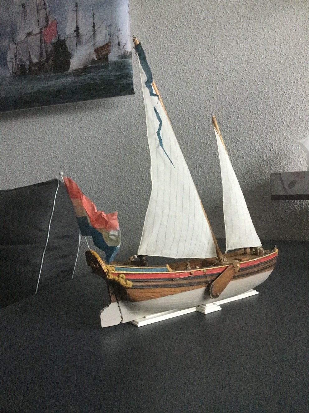
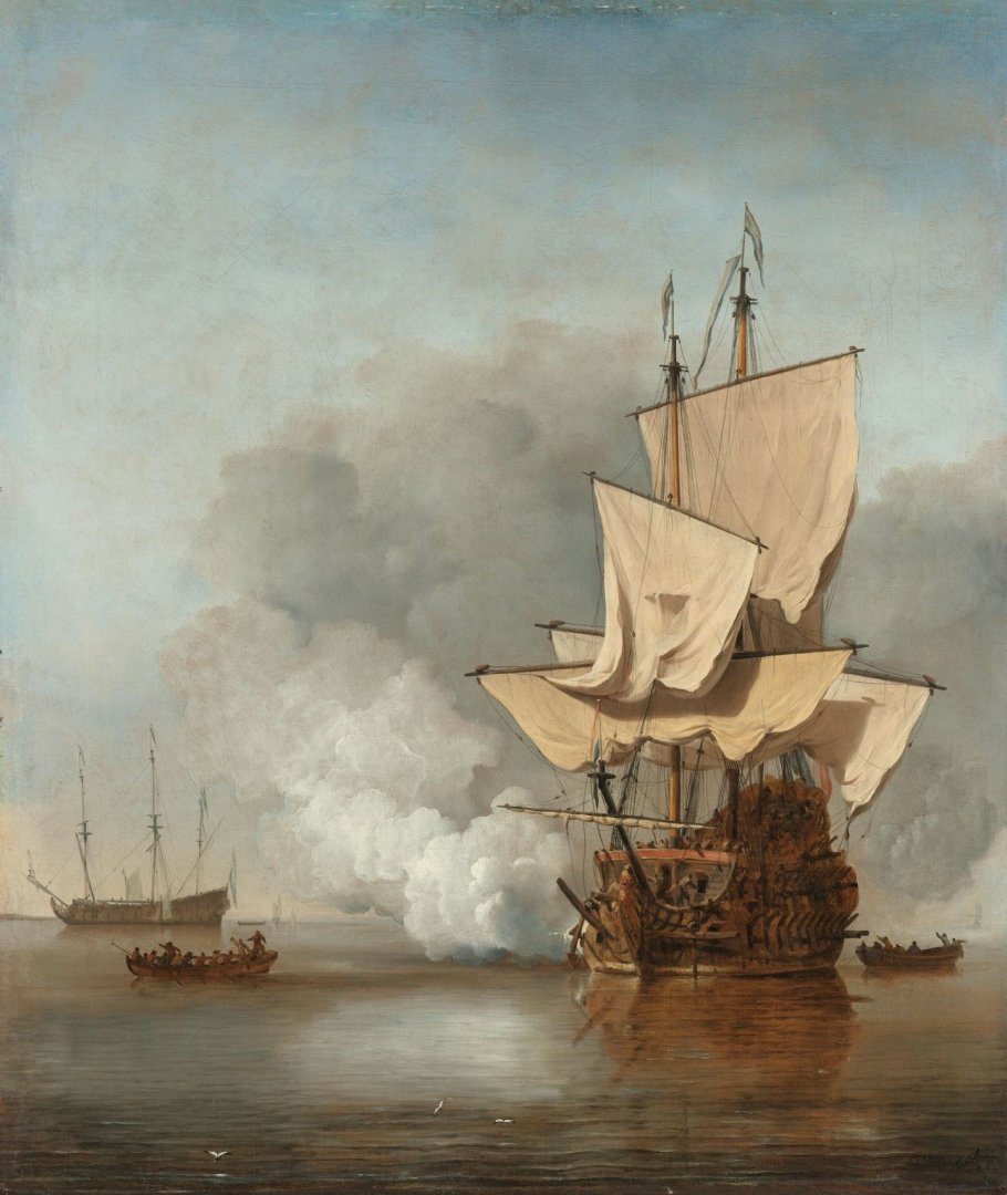
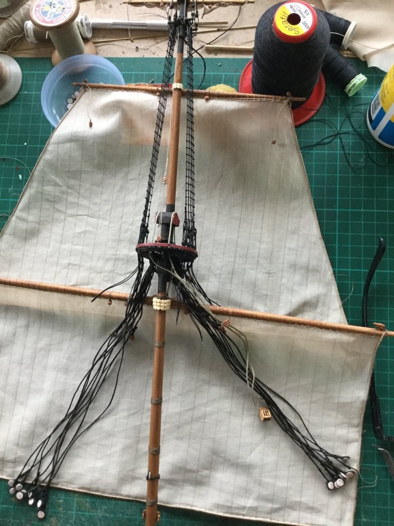
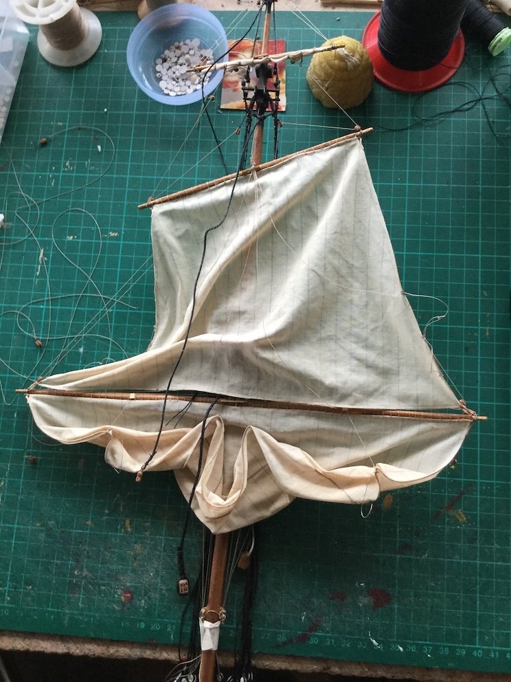
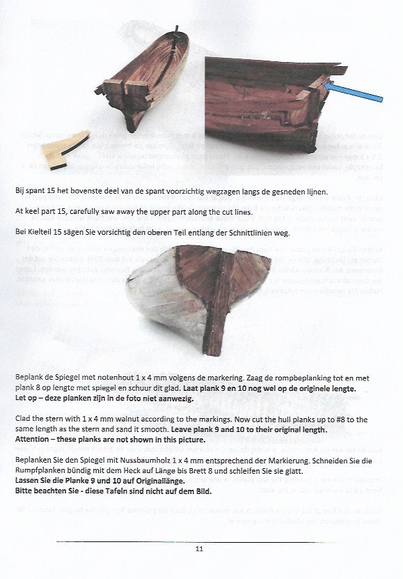
It has been a while since we had the short conversation about the material to choose for natural looking sails. I jumped into several experiments after wefalcks suggestion of using paper for sails and I managed to get all the paper I needed. However, I never succeeded in creating the result I was looking for. So I went on searching for the right kind of textile. Thanks to one of my former collegues at the museum I managed to get some stuff called 'voile cotton' that answered my needs. Since the hull of the man-of-war I referred to earlier in the thread was finished, I decided to try my hand on an experiment with almost windless conditions like on this Van de Velde painting in the Rijksmuseum: Because I don't want to hurt my back too much I prepare my masts, including blocks, sails and lines on the table. In this picture sails and blocks are in position, lines still have to be added. Here the sails are sprayed with starch and dried with a hair-dryer, while modeling them in the shape I want. Purpose is of course to get natural shapes, expressing the weight of the sails together with the little wind that furls them. Hard to explain I'm afraid. All the lines are temporarily belayed at the mast-foot, they will be attached at the right locations later. And this is how it will all look after completion. The main mast still has to be done. The shrouds and stays of the foremast can be fixed now, after which braces, bowlines and tacks follow. Sorry for my lousy photography techniques. By the way, my pleasure vessel experiment, the subject of this (a bit confused) thread, has led to a kit, produced by Kolderstok (http://kolderstok.nl/speel-jaght.html). Kits are not my cup-of-tea, but this one is unusual in the sense that the traditional egg-box system with its terrible straight-planks-method has been replaced by a sort of shell-first technique. Because Rene Hendrickx, my super-Belgian partner-in-crime, created the shapes of all the planking for the boat, the kit is built by using a pdf-mold, used to temporarily support the laser-cut planking. Thus an empty shell is created after lifting from the mold, which can be finished like a real hull. A new development in kits in my (limited) vision for a very reasonable price. Sorry if I overlooked kits which followed the same method, as I said, kits are not really a point of interest for me. Here a page from Kolderstock's three language manual, showing what I mean.

-
Yes, it's definitely water based, probably some methyl alcohol as well. At least it does not smell as sharply as the car fillers. Don't think you can use other fillers though. I tried a lot and this one works the best, but the others weren't too bad either. I read on the tube: mixture of 5 chloor-methyl-4-isothiazolin-3-on [EC no 247-500-7] and 2-methyl-2H-isothyasol-3-on [EC no 220-239-6](3:1). Now, if that is clear to you I would be surprised, it does not ring a bell for me. But it's great stuff! :-))
- 65 replies
-
- 4
-

-
- fish hooker
- fishing
- (and 2 more)
-
Need CAD type program
Ab Hoving replied to Sambini's topic in CAD and 3D Modelling/Drafting Plans with Software
Hello Terry, My compliments for your research and vast report on your activities. You are doing great. I am afraid you estimate me higher than I am. As for Delftship I have never had the intention to work with the program, having already so much help from my talented and enthusiastic friend Rene Hendrickx. So in a technical way I am not the one who can add something to your considerable efforts. I will send this thread to Rene though, but don't expect too much of it. Not because Rene is unwilling, but because being Belgian his command of English is at a lower level than his Dutch (or Flemish) and French. Maybe he will pass some remarks about your work through to me and in that case I will certainly keep you posted. Keep up the good work, Ab -
Hello Tony and Tony... Funny how a thread from a year ago suddenly appears to be alive.:-) The question about the right kind of filler is a very good one. It does make a difference which type is used. That is because some kinds are quick drying, but only at the surface and they shrink when at last the lower layers have dried too. I am afraid you have to test some brands yourself, because I wonder if the type I use is available in your country too. The stuff I like most, because it does not shrink, even if a layer of 2 mm is applied is: Houtplamuur (wood filler) Universal by Alabastine. It does not dry as quick as for instance the fillers that are used in car repair, does not smell at all and can be sanded after an hour, provided you did not smear too much and too thick. Use thin layers of filler and allow to dry as long as you can. You can get information at: info@alabastine.nl Hope this helps. Ab
- 65 replies
-
- 7
-
-
- fish hooker
- fishing
- (and 2 more)
-
Need CAD type program
Ab Hoving replied to Sambini's topic in CAD and 3D Modelling/Drafting Plans with Software
He sends you his best wishes and if there are any questions...shoot. -
Need CAD type program
Ab Hoving replied to Sambini's topic in CAD and 3D Modelling/Drafting Plans with Software
It is really a pleasure seeing that Rene's lessons did lead to beautiful results. Well done! -
Just because you asked, Bob: Shellac seems to be a product we forgot. That's a pity because it is a most versatile means of protection for many materials. I once read somewhere that the characteristic 'helmets' of the English Bobbies were made of velt soaked in shellac. Don't know if it is true. My experience with it as a varnish is that it works fantastically on wood. Many late 18th and 19th century models in my depot were done with it and only in cases the models were exposed to a lot of water, for instance as a result of a leaking roof, the material flaked and showed up white. Mostly because the wood underneath worked. It was also easy to replace. Alcohol removed the old remains almost immediately. Bringing on new layers was another story. All remnants had to be removed completely or they would show up very nastily after drying. That indicated that it was hardly possible to touch up an existing layer with some damage. If it had to be repaired, all had to come off. Bringing on the first layer was never a problem. But a second layer could end up in a disaster if the first one was too thick and a third layer almost always was a no go, unless you worked very quickly and never touched areas for a second time with your brush, otherwise you most probably ended up with a nasty slippery looking result. It could be sprayed though, but the result was (in case you did not have a spraying box with air suction) that in a matter of seconds you were standing in a thick fog of dried floating particles of shellac. For french polishing it was great too, though very time consuming. I have used it occasionally for securing knots, but always from a container that was deliberately left open for a couple of days. The material became more condensed and spreading through the textile was limited much more than when using the freshly diluted stuff. To be honest, I don't use it any more after I retired, although I do have a few bottles of it standing on the shelf and sometimes I look at them with a vague feeling of home-sickness. I use anything I can lay my hands on, even CA, to force my materials to behave the way I want them to and I don't care much about the longevity of my products. We are not here to stay forever and the same is true for my models. I'm only interested in their looks, not in their age :-).
-
You Eastern European guys are so extremely neat in your work, which almost makes me jealous. You are years ahead of here in Western Europe.
-
Hello Eberhardt, Mr. Schmidt seems to have a great idea for sails during a windless moment. To capture such moments in hanging sails is one of the most difficult things to achieve. I wonder if it works for billowing sails as well. Anyway, I wil reactivate my contacts with my former collegues, hoping they can help me testing this new idea. Thanks for your reaction and also to all the people who 'liked' my contribution. I suppose we can safely close this thread now. Ab
-
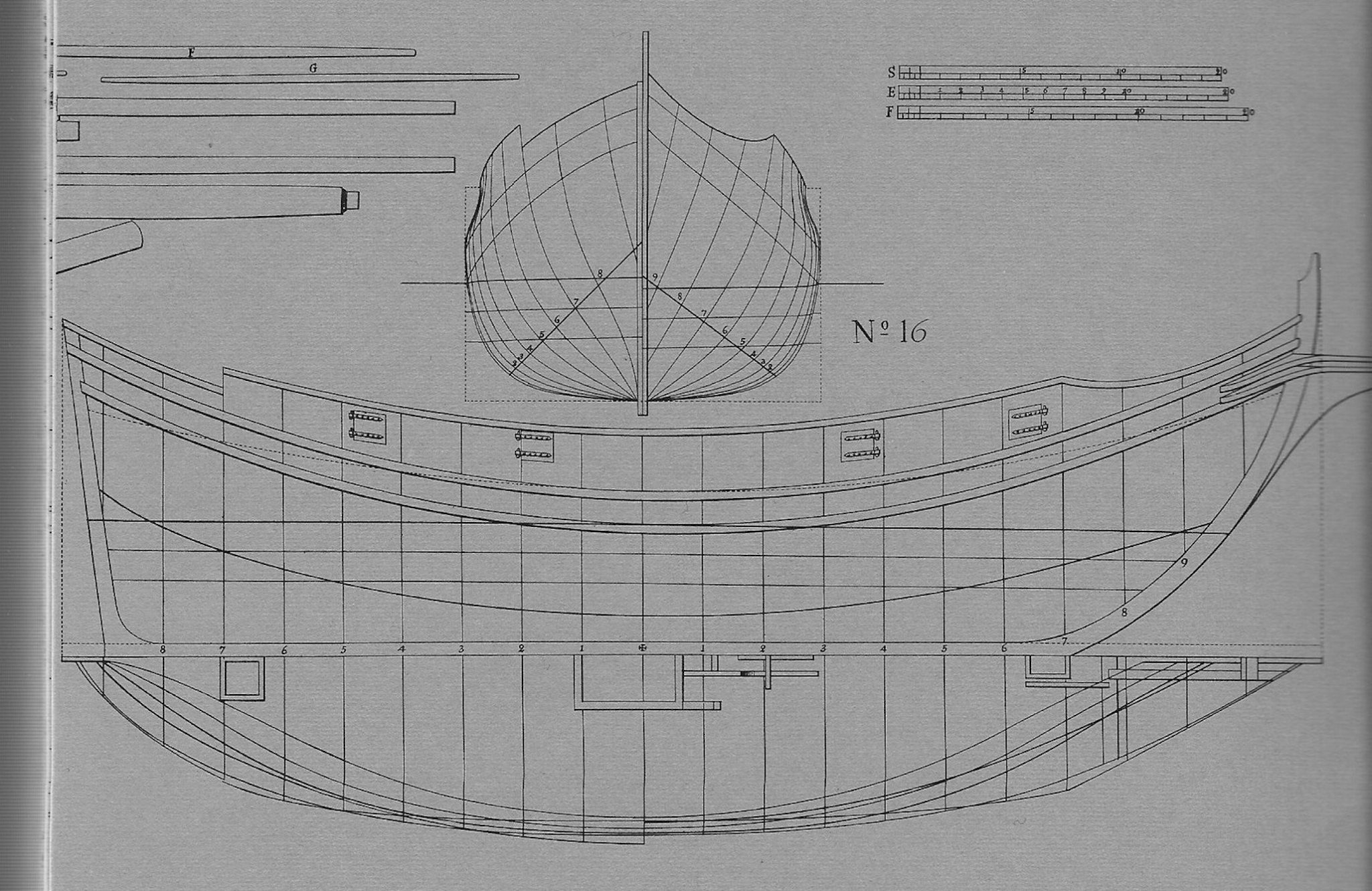
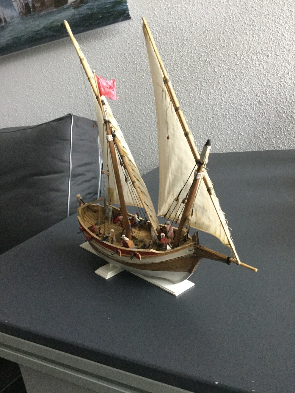
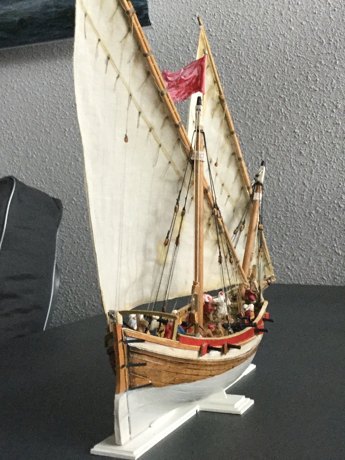
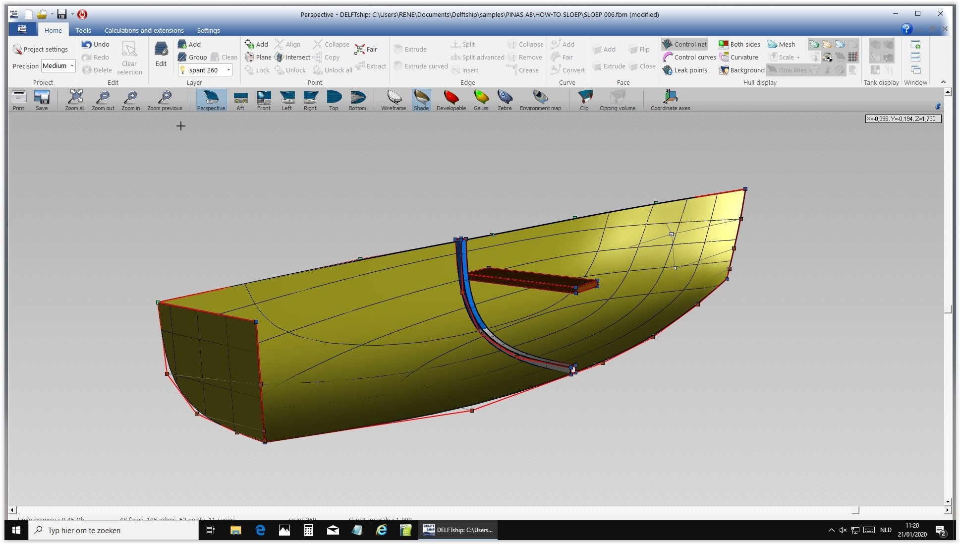
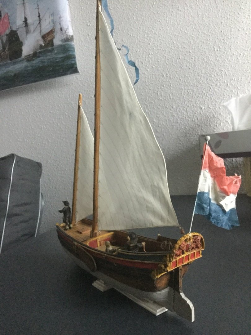
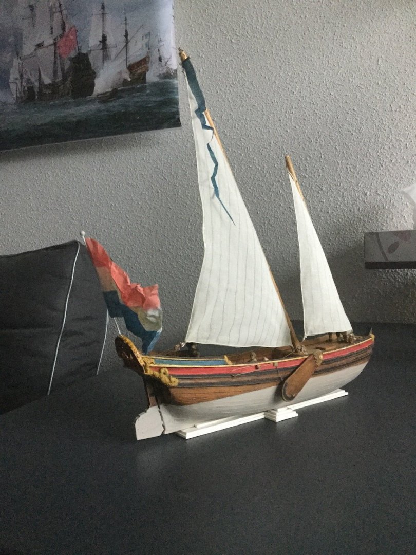
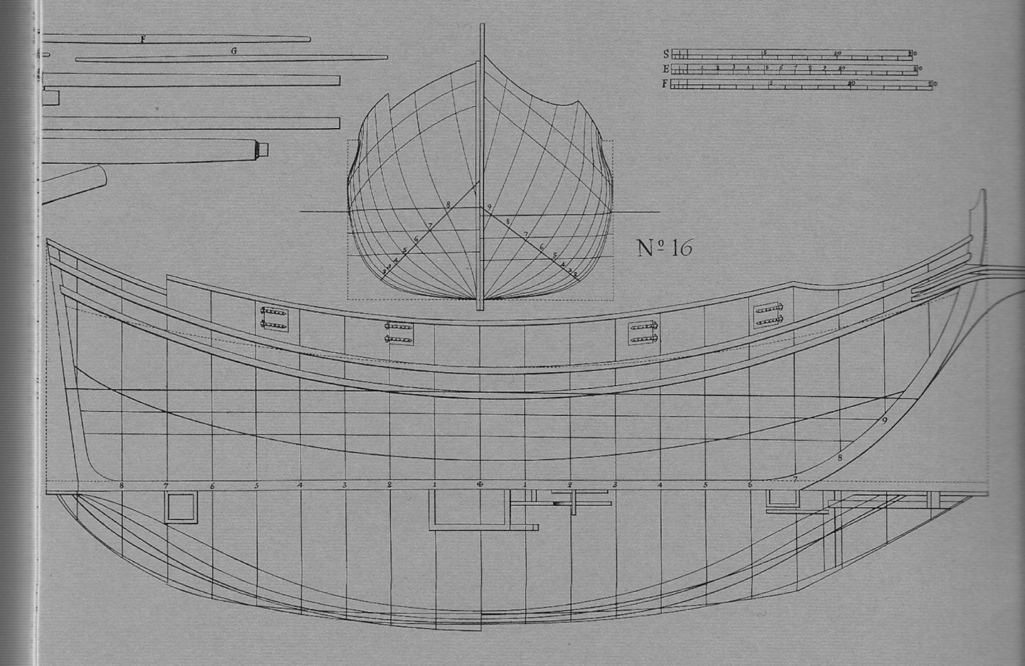
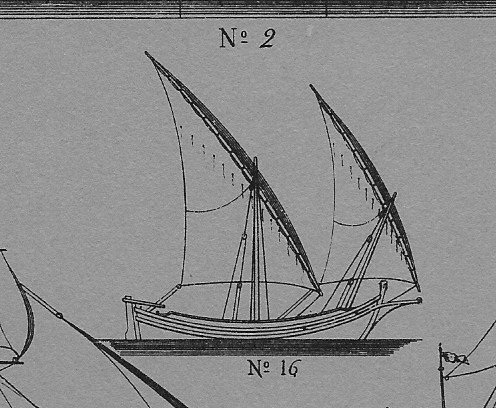
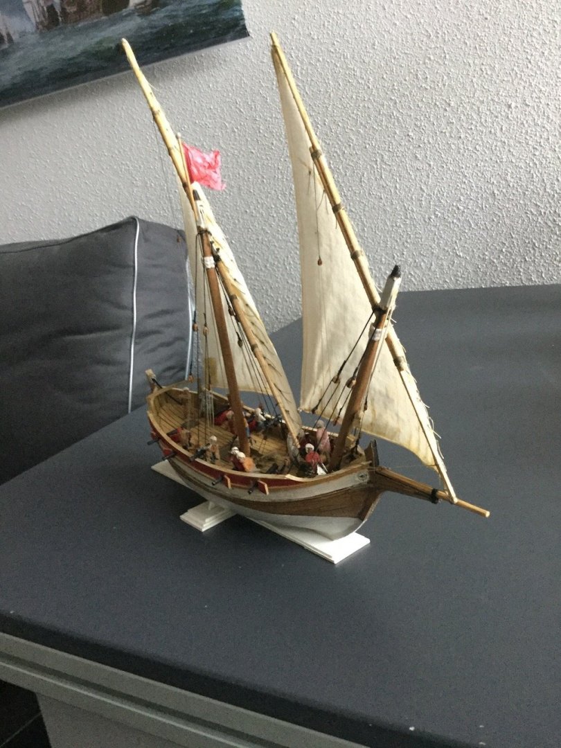
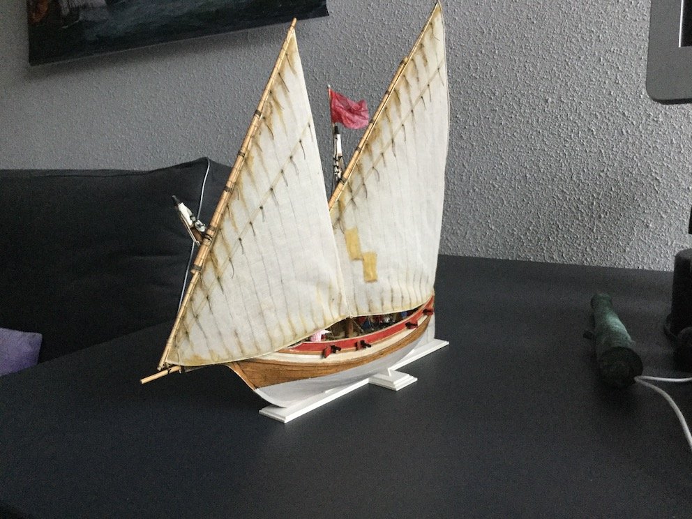
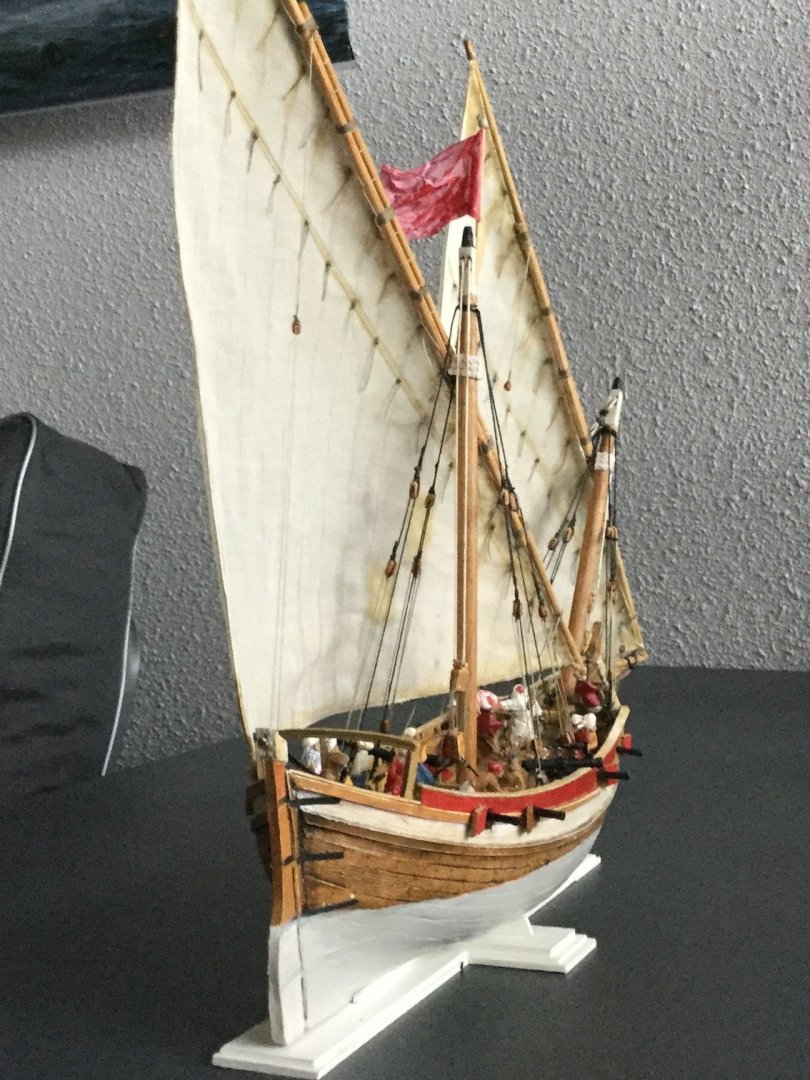
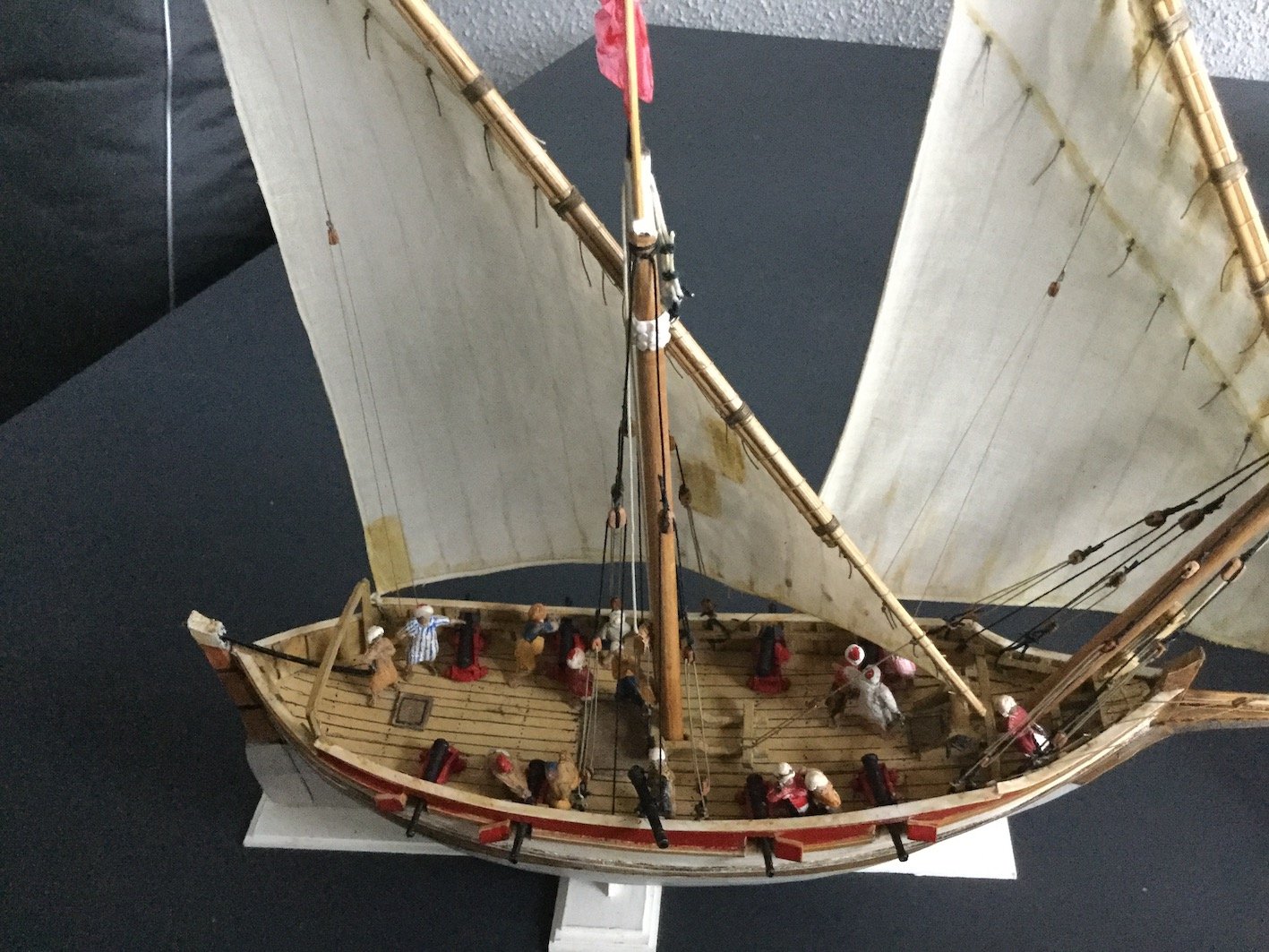
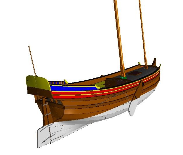
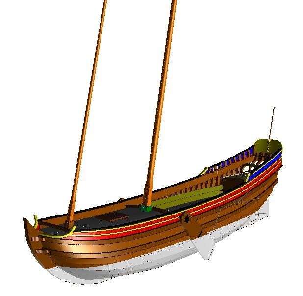
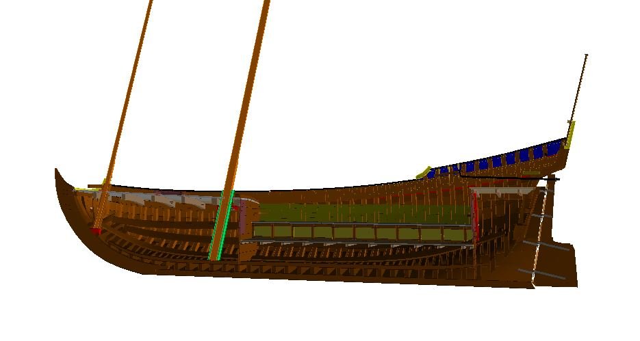
I left this thread alone for a long time. Not because I lost interest, but there were so many more things on my table (an on my mind actually). First I should get back to the discussion about the materials used for sails. I always used a very fine linen cloth to bellow it with starch and a hair dryer, but the bottom of my stock becomes visible and wefalck suggested I might give paper a try. In itself that seemed logical, as I am using paper for the hulls as well, but I never found my way in 'building' sails. A former colleague at the museum directed me to a gentleman in Haarlem (also a restorer) who had stocks of all sorts of paper. Indeed he was kind enough to supply me with some various sizes of wonderful hand made Japanese paper. I tried to make sails with it, but never succeeded in producing a real natural shape with it. Another former colleague sent me new textile material. Not exactly what I used before, but very well suitable for my purposes. So I made new sails for the yacht with it. Originally the question of the material used arose because my sails always look too clean and tidy. I thought it was impossible to apply paint after I used starch to get a natural shaped sail. For reasons of practicing Seahorse's method of double planking paper hulls without the use of filler I needed draughts of a simple vessel. I chose a tartan from Chapman's wonderful collection of draughts Architectura Navalis Mercatoria because of its simple shape and I successfully applied Seahorse's method in the construction of the hull (thank you Tomek). Rigging a lateen sail ship is very quick compared with square rigged ships, so I thought I give painting its sails a try. If things went wrong it would not take much time and effort to replace them. Anyway, painting starched sails with Acrylic paint appeared to be possible indeed, although I need a lot of practice before the result will be really satisfying. I like this small vessel with its exiting lines very much and wonder why I always get back to Dutch vessels. Probably because foreign ones ask so many more questions I cannot answer than Dutch ones... A week later my son and I received a request to do a book sleeve for a book about a fluit ship that was taken by a North African corsair. Pure coincidence. Once the real pictures are taken and Emiel has done his graphic job I will show the results. In the mean time my miracle-Belgium friend Rene Hendrickx finished the 3D model of the pleasure vessel and since this little boat is still the subject of this thread (believe it or not) I can offer the draught to anyone who wants to build this lovely ship type and we even have the shape of the planks right now. If you have the free downloadable shipbuilding program DELFTShip on your 64-bits computer, I can even send you the file, so you can view this model in 3D inside and out. Just send me a PM in case you are interested. Back to the working table, where a Dutch 1600 galley waits for my attention. Another project I got lured into by my former boss at the museum, Peter Sigmond, who is about to publish a book about that stormy period in Dutch history. But that model is again part of a totally different story, maybe another time...
-
Need CAD type program
Ab Hoving replied to Sambini's topic in CAD and 3D Modelling/Drafting Plans with Software
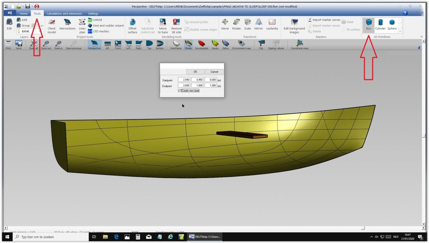
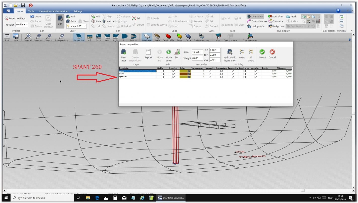
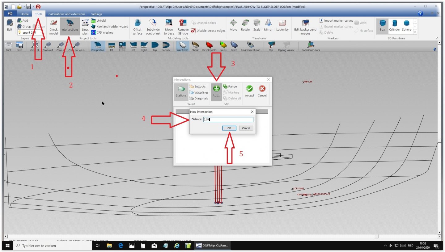
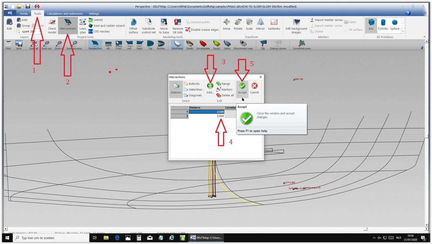
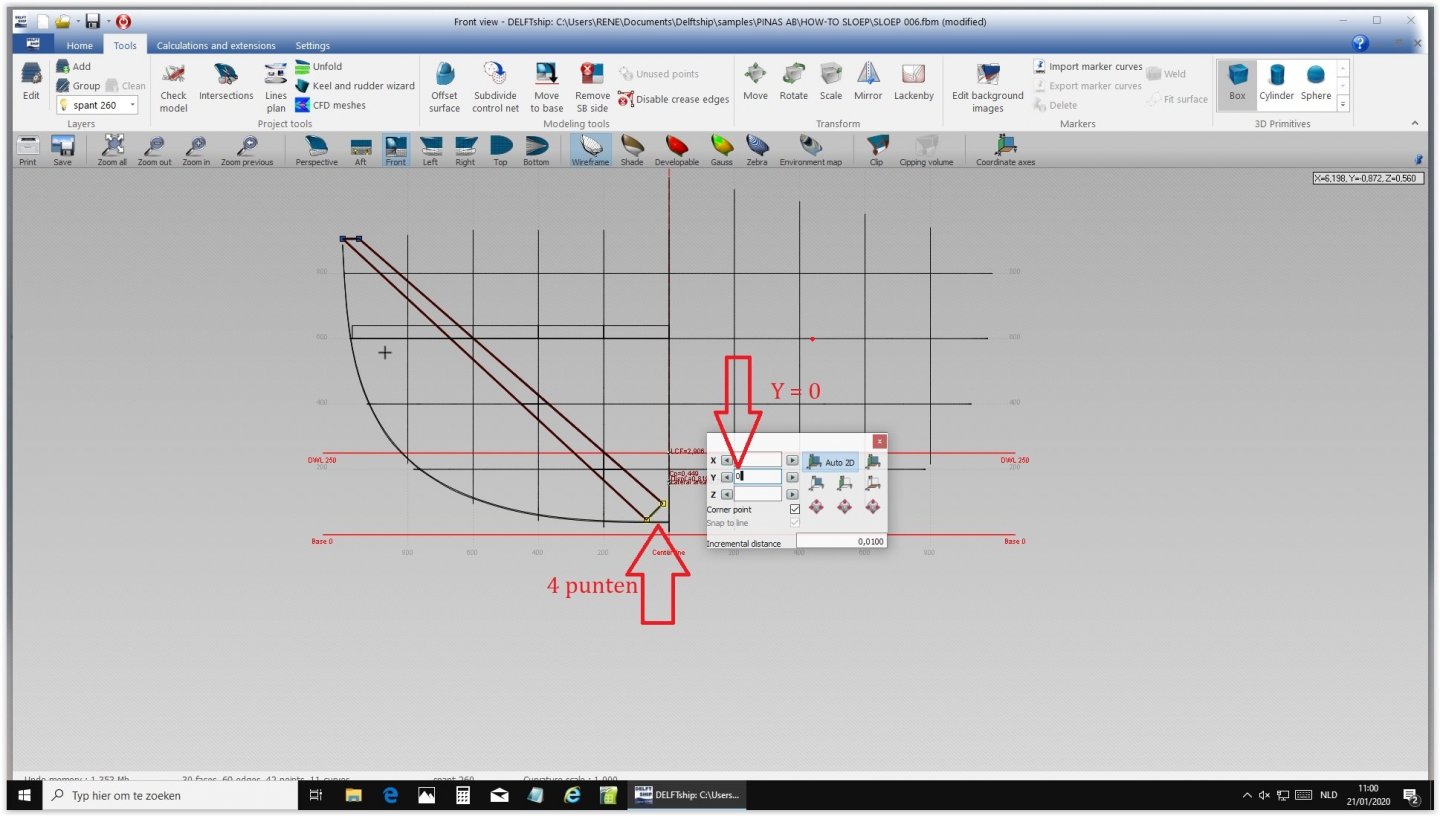
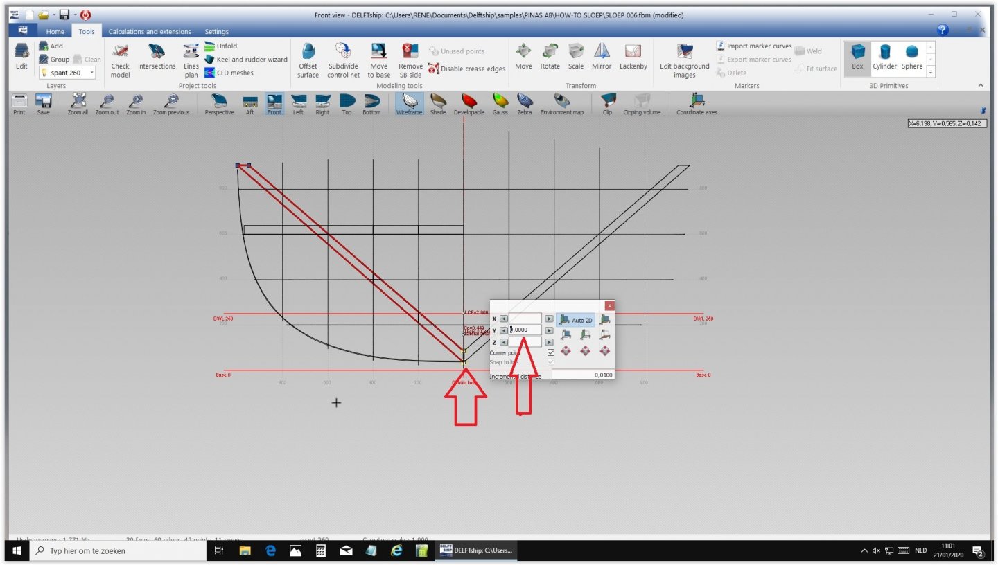
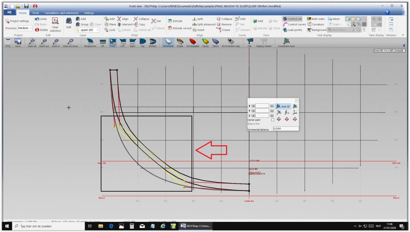
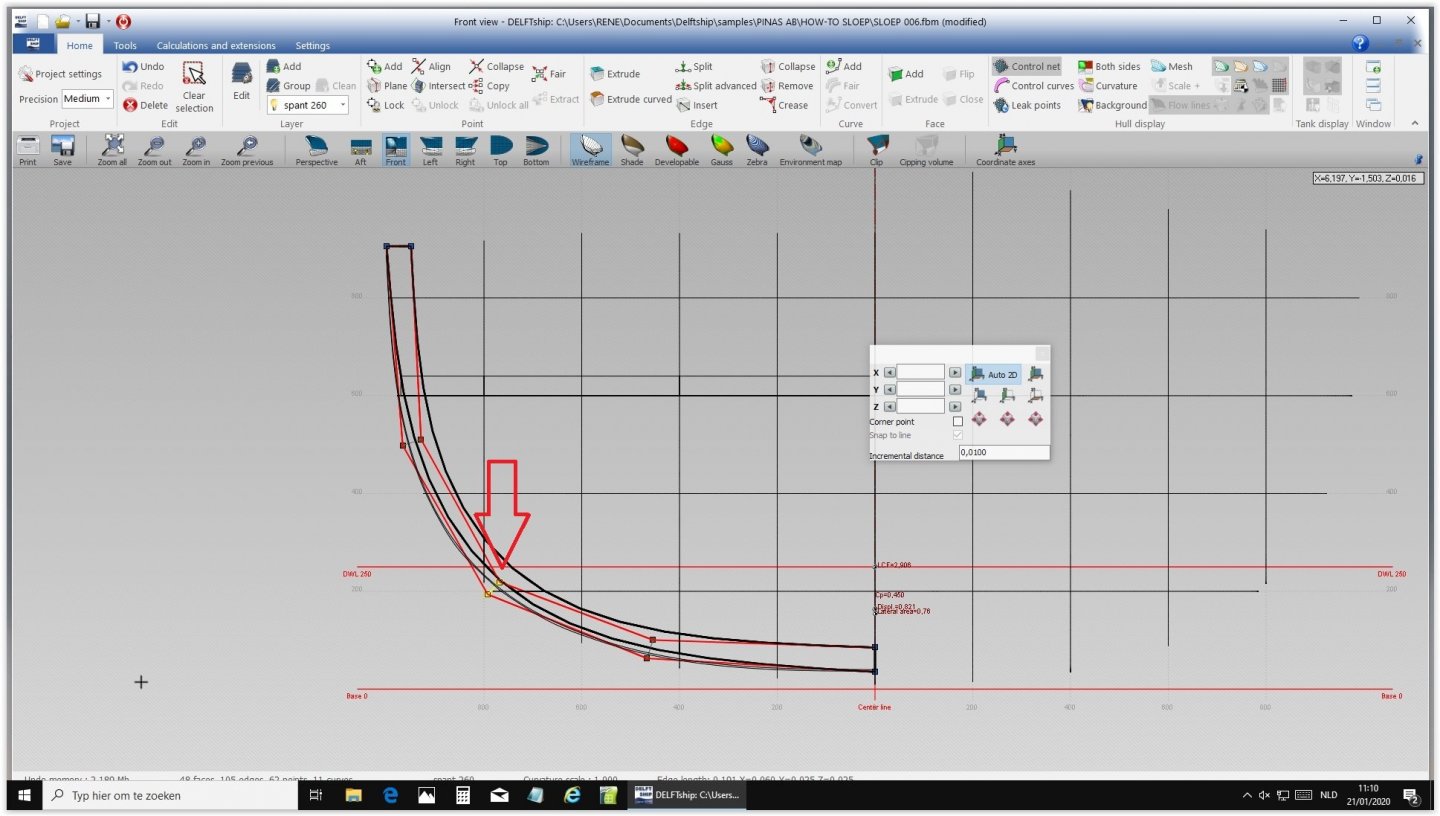
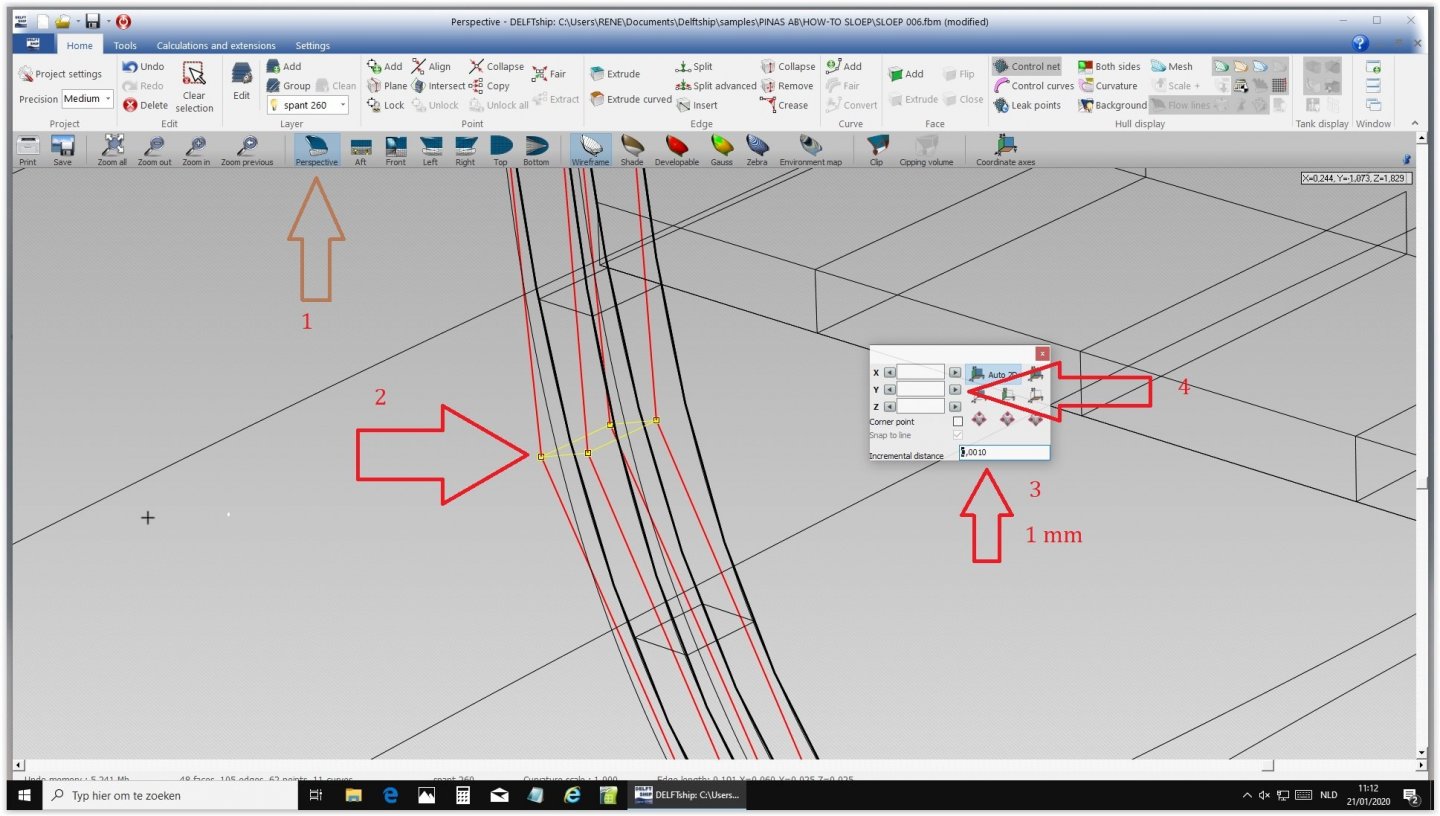
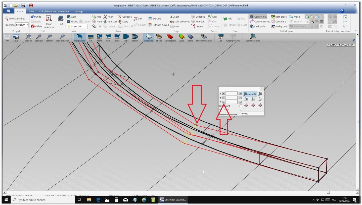
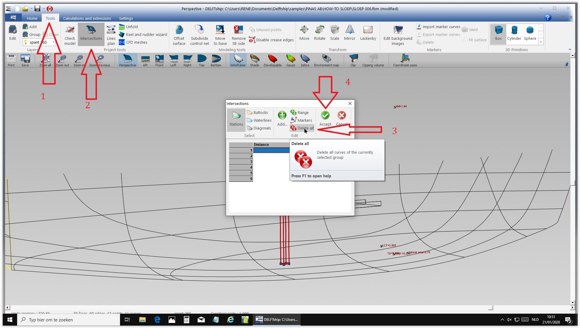
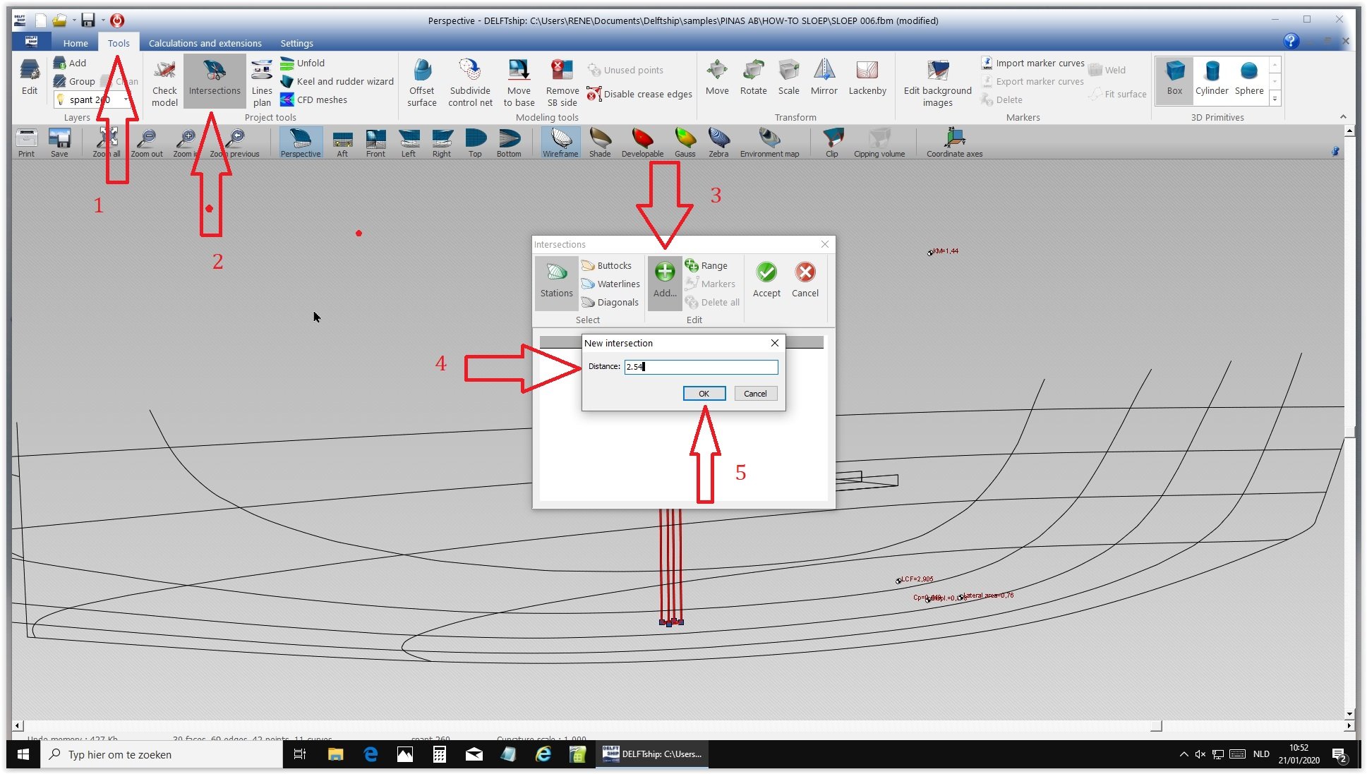
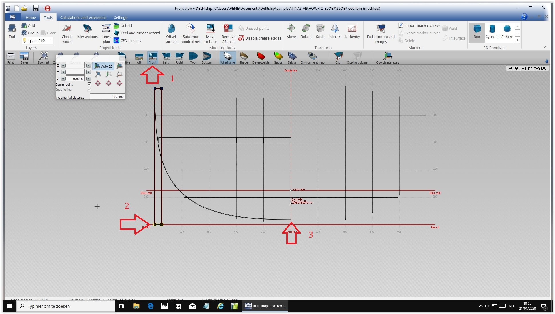
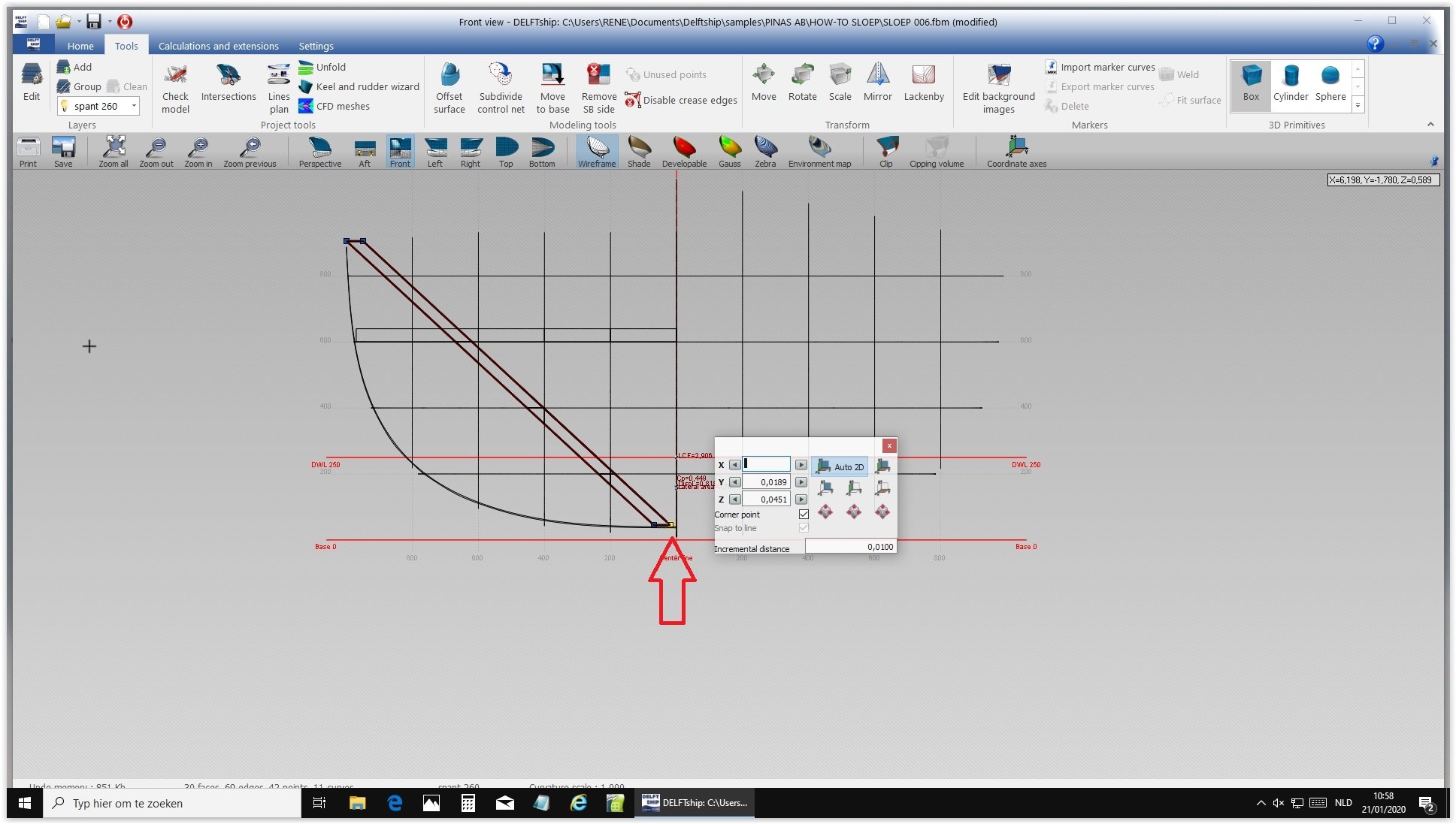
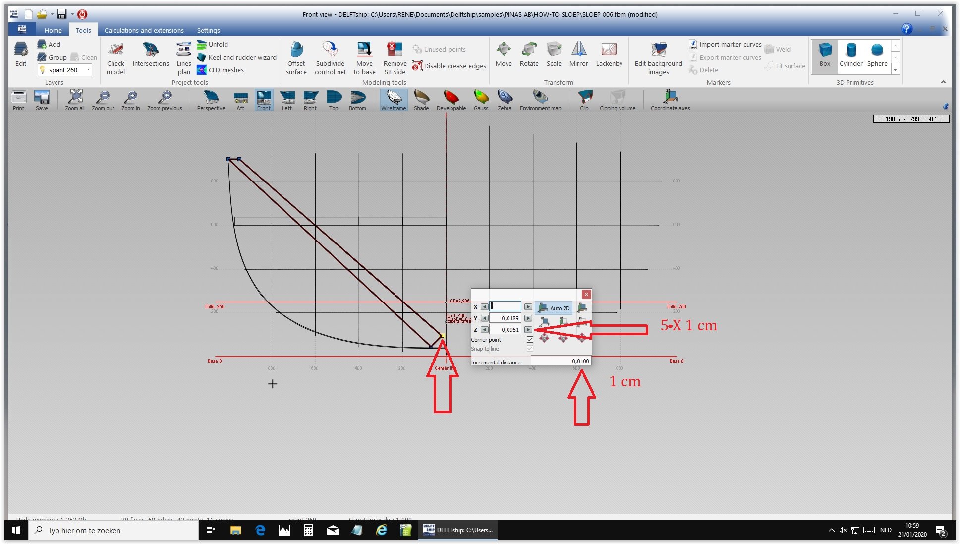
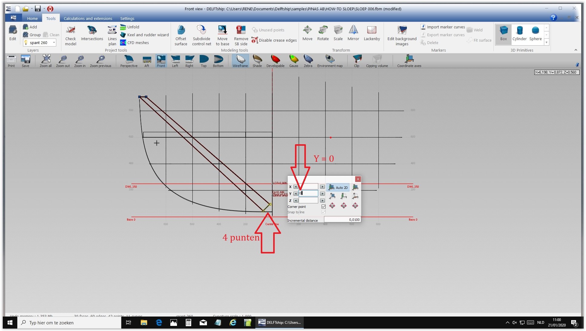
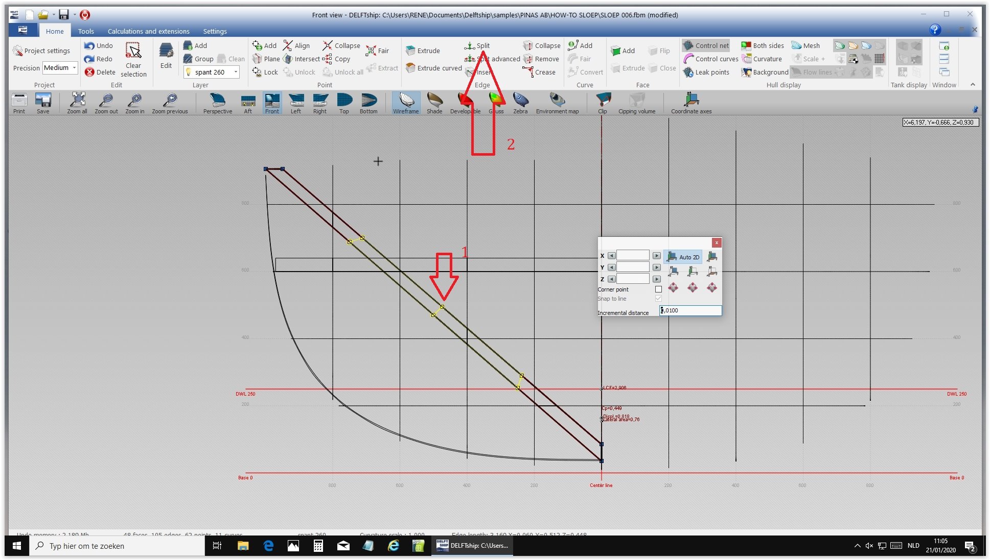
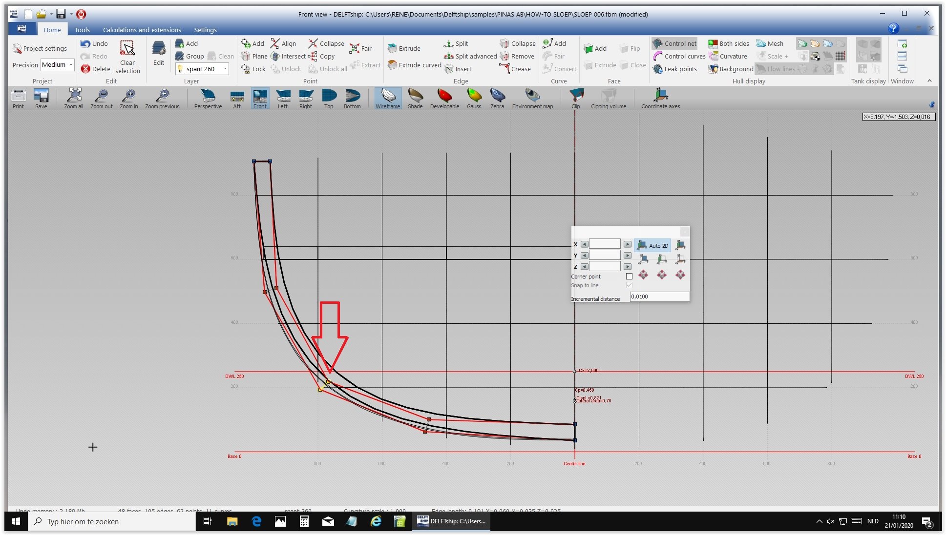
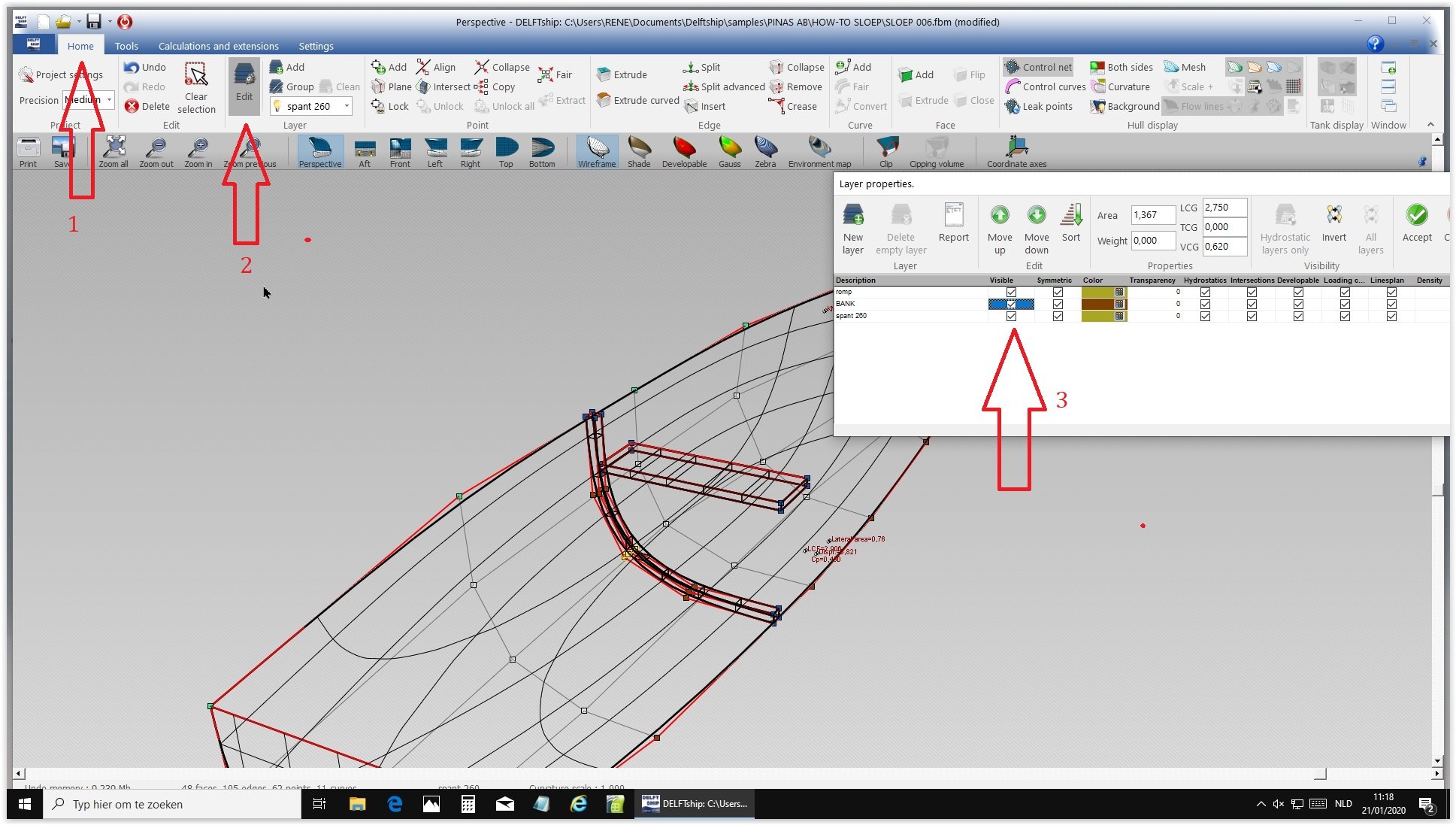
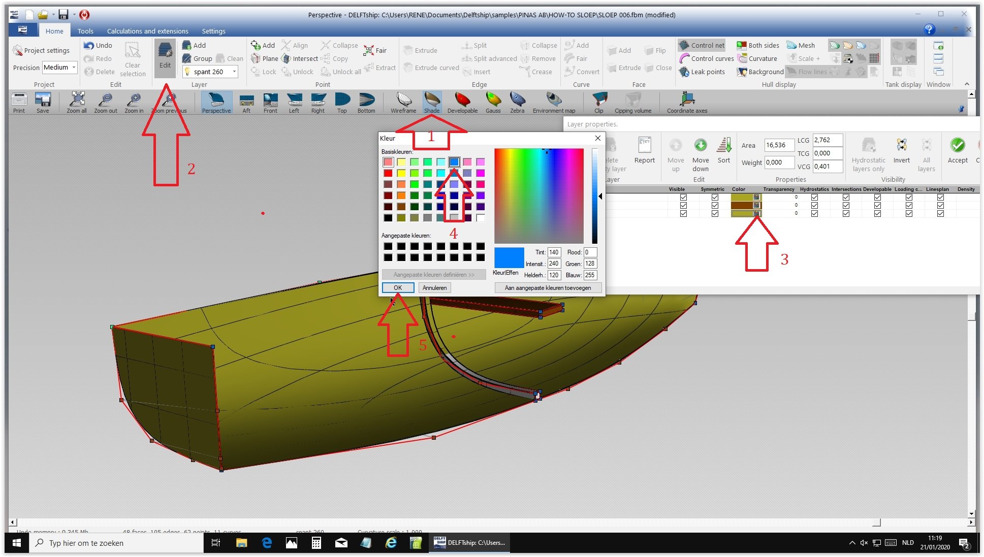
OK, here comes how to create a curved shape inside a vessel. First create a plank the way we did last time. X 2.54/2.60 , Y 0.95/100 , Z 0.00/1.00, new layer Change the name of the new layer Delete all stations Create station 2.54 Create station 2.60 Move the lower side of the plank to the center. Select four lower points by pressing Ctr and dragging with the mouse around the points and move them to the center Select two points and drag them 5 centimeters up Center the four lower points. Drag the four points to the bottom of the frame. Drag these four points to the underside of the frame Select the four long lines and split, and the same for the upper and lower half Select the 12 points that were created this way and drag until the upper and lowerpoints touch the frame. Select the four middle points and drag them till they touch the frame Select Perspective and take the four upper points. Change Y until the lines match Match the lower points by moving Z and Y an equal numbers Make all layers visible again Open Layers and change color A blue frame is made just behind the bench That's how simple it is...