John Gummersall
-
Posts
265 -
Joined
-
Last visited


-
 Capt. Kelso reacted to a post in a topic:
Chaperon by John Gummersall - FINISHED - Model Shipways - Scale 1:48
Capt. Kelso reacted to a post in a topic:
Chaperon by John Gummersall - FINISHED - Model Shipways - Scale 1:48
-
aaronc reacted to a post in a topic:
Grand Banks Dory by palmerit - FINISHED - Midwest Products - 1:12
-
 mbp521 reacted to a post in a topic:
Chaperon by John Gummersall - FINISHED - Model Shipways - Scale 1:48
mbp521 reacted to a post in a topic:
Chaperon by John Gummersall - FINISHED - Model Shipways - Scale 1:48
-
Admiral Rick reacted to a post in a topic:
Picket Boat #1 by John Gummersall - FINISHED - Model Shipways - Scale 1:24
-
Admiral Rick reacted to a post in a topic:
USN Picket Boat No. 1 by Seems ok to me - FINISHED - Model Shipways - 1:24
-
Admiral Rick reacted to a post in a topic:
USN Picket Boat No. 1 by Seems ok to me - FINISHED - Model Shipways - 1:24
-
Admiral Rick reacted to a post in a topic:
USN Picket Boat No. 1 by Seems ok to me - FINISHED - Model Shipways - 1:24
-
Old Collingwood reacted to a post in a topic:
Stage Coach 1848 - John Gummersall - Artesania Latina - Scale 1:10
-
king derelict reacted to a post in a topic:
Stage Coach 1848 - John Gummersall - Artesania Latina - Scale 1:10
-
king derelict reacted to a post in a topic:
Stage Coach 1848 - John Gummersall - Artesania Latina - Scale 1:10
-
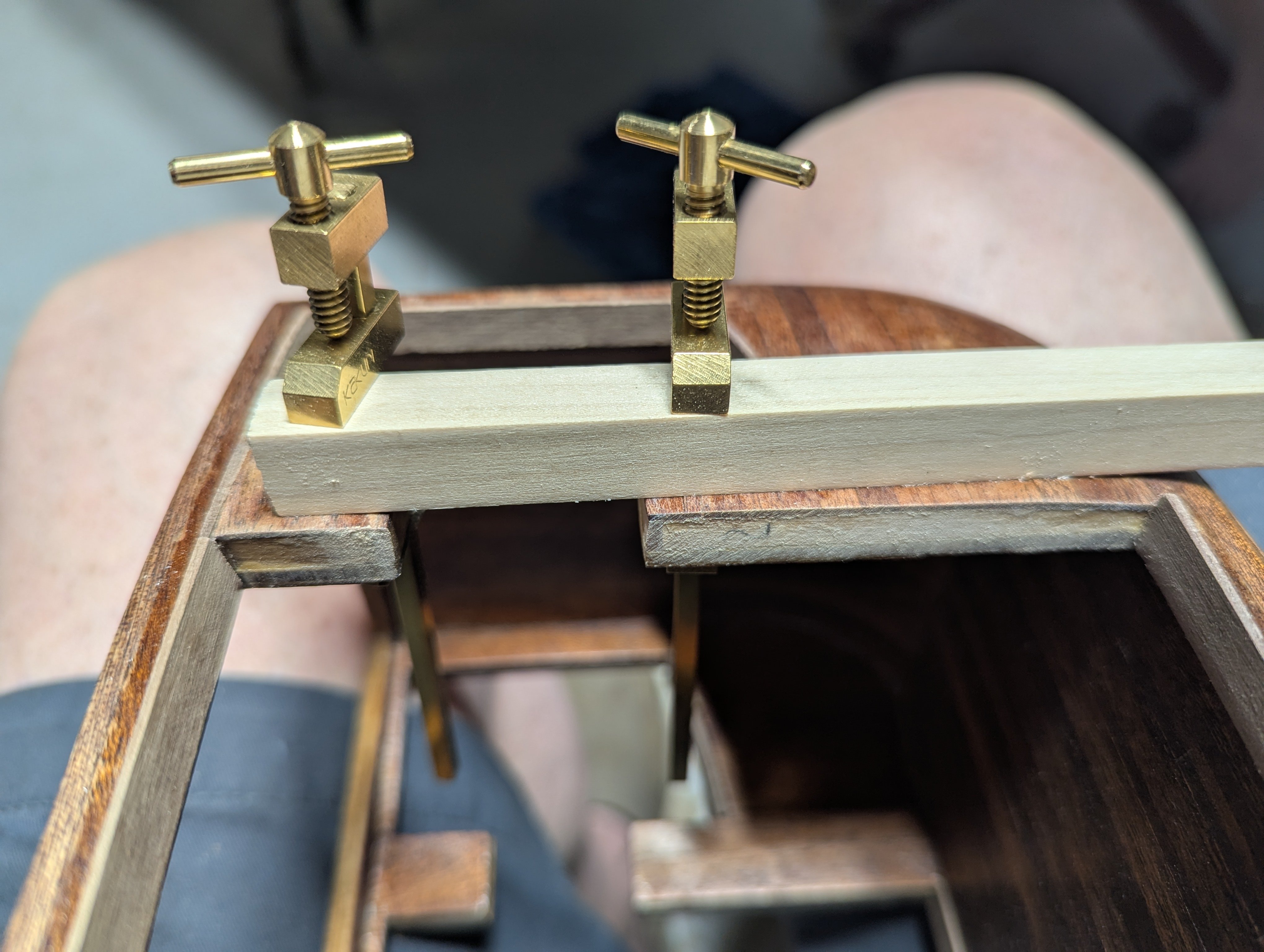
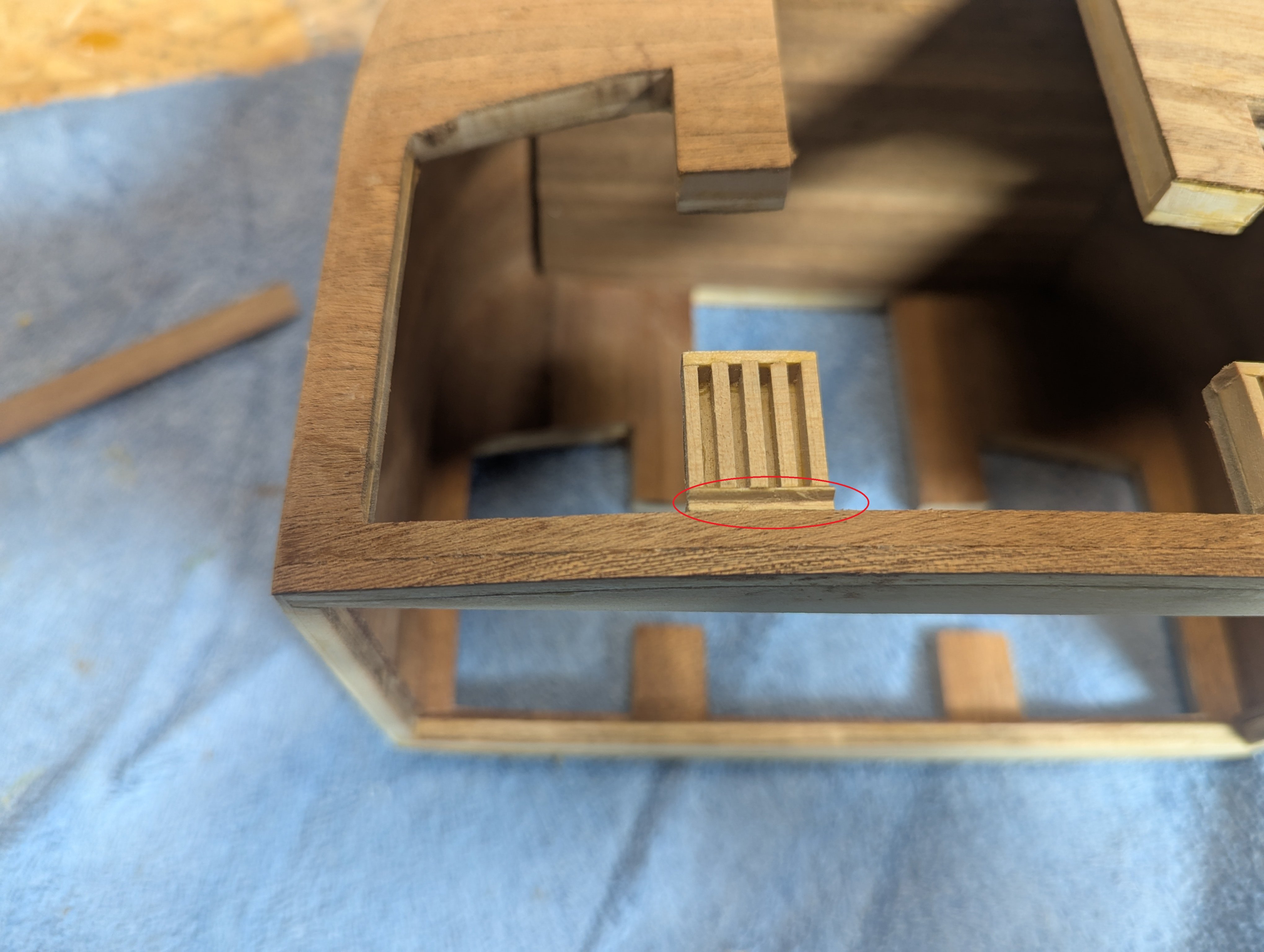
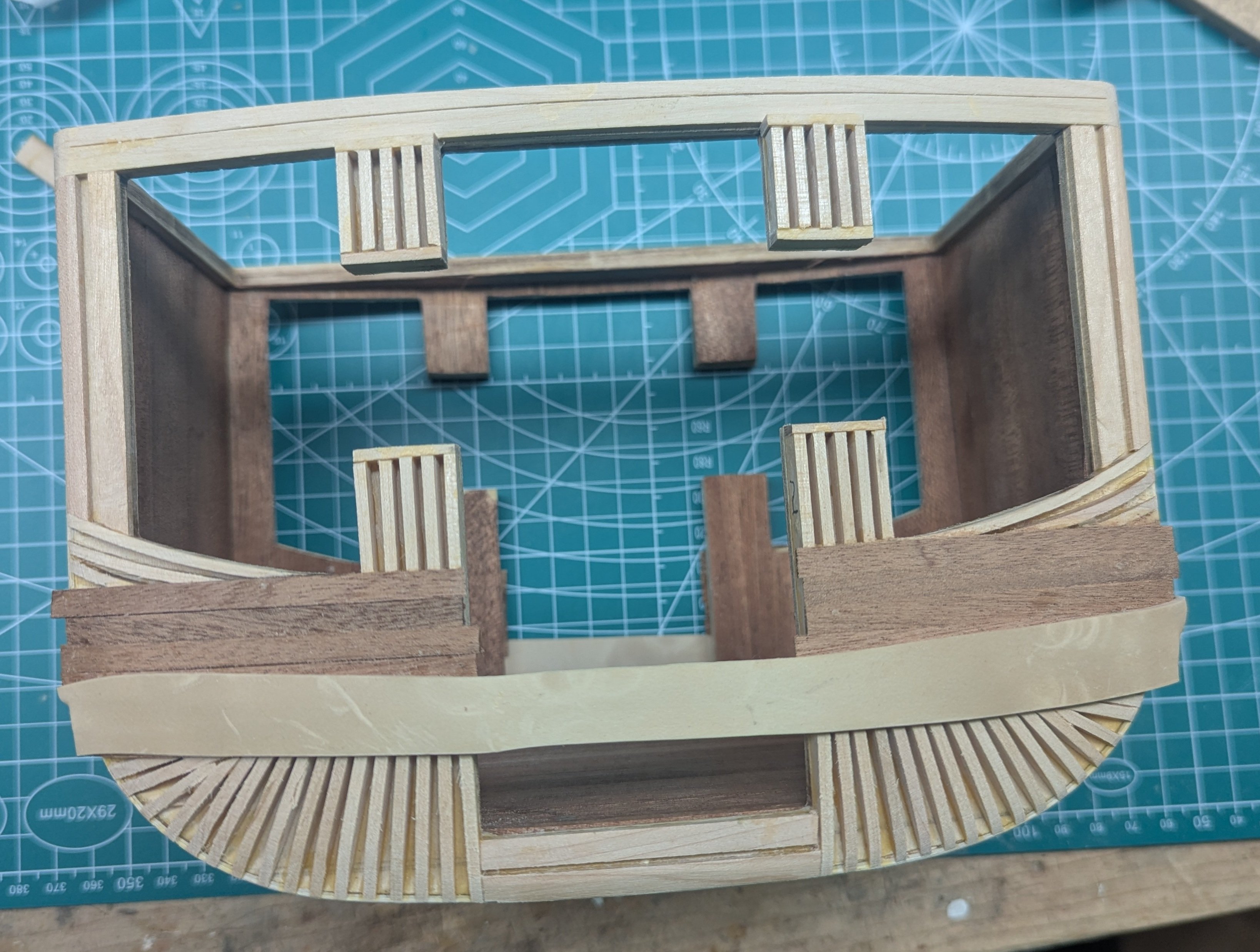
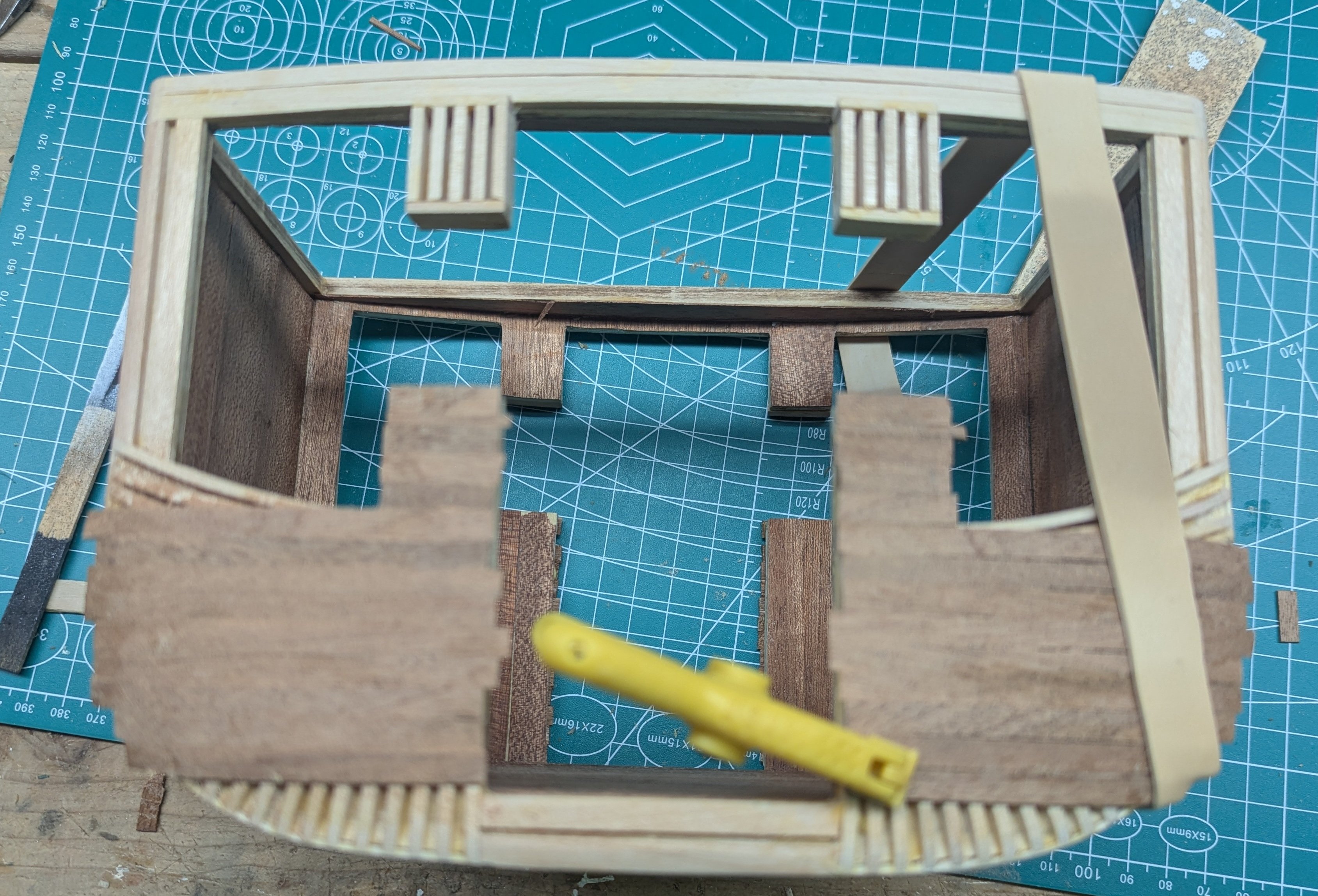
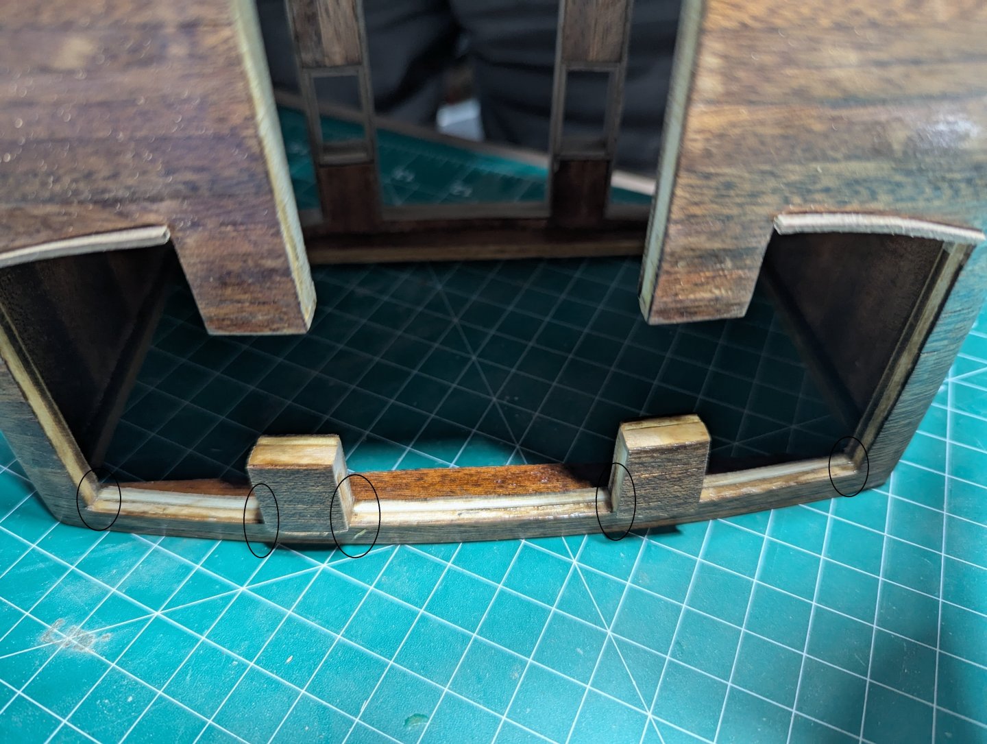
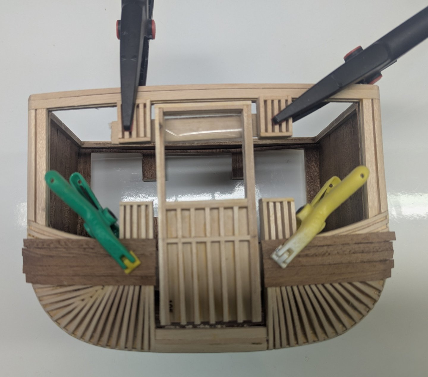
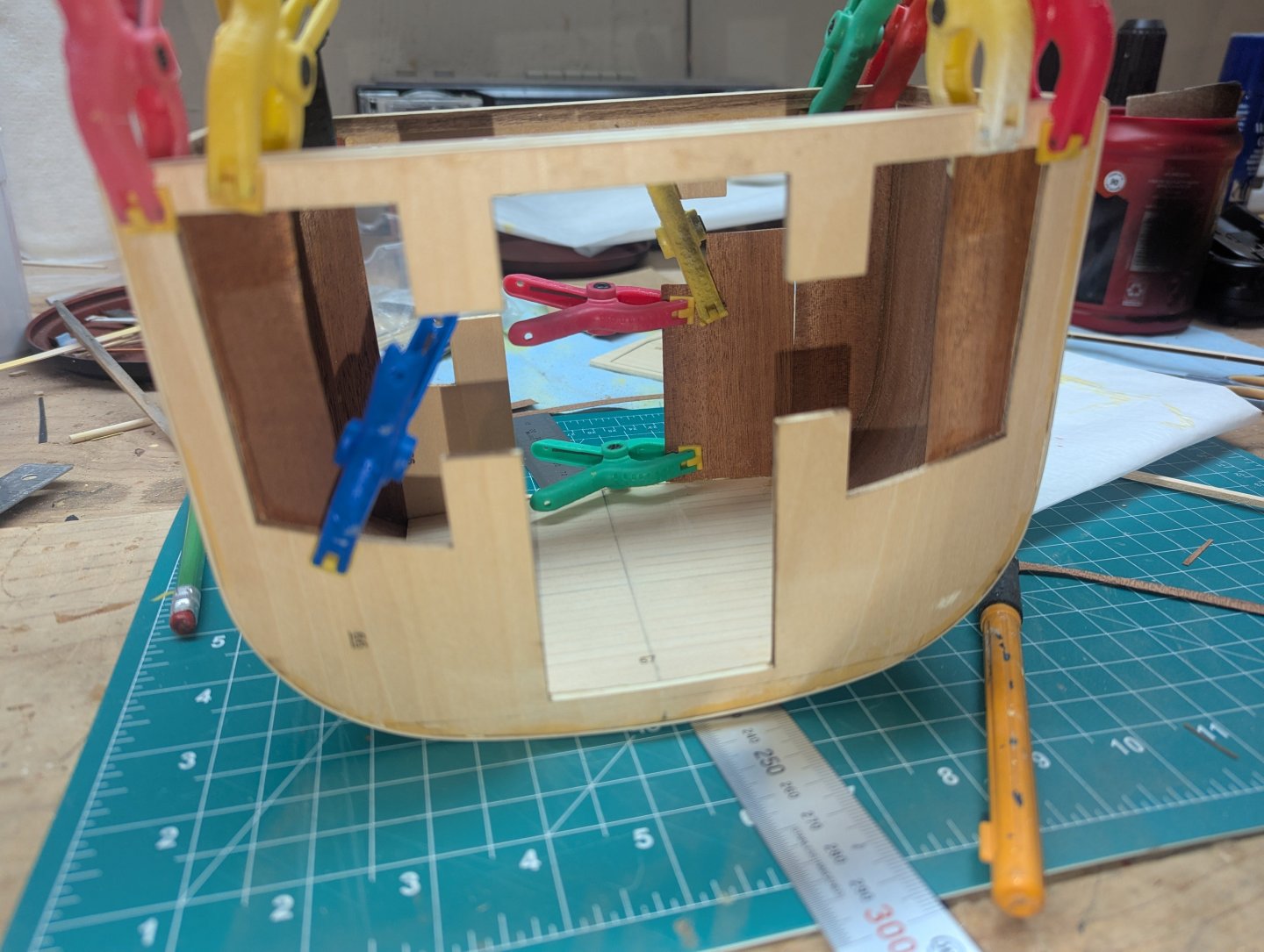
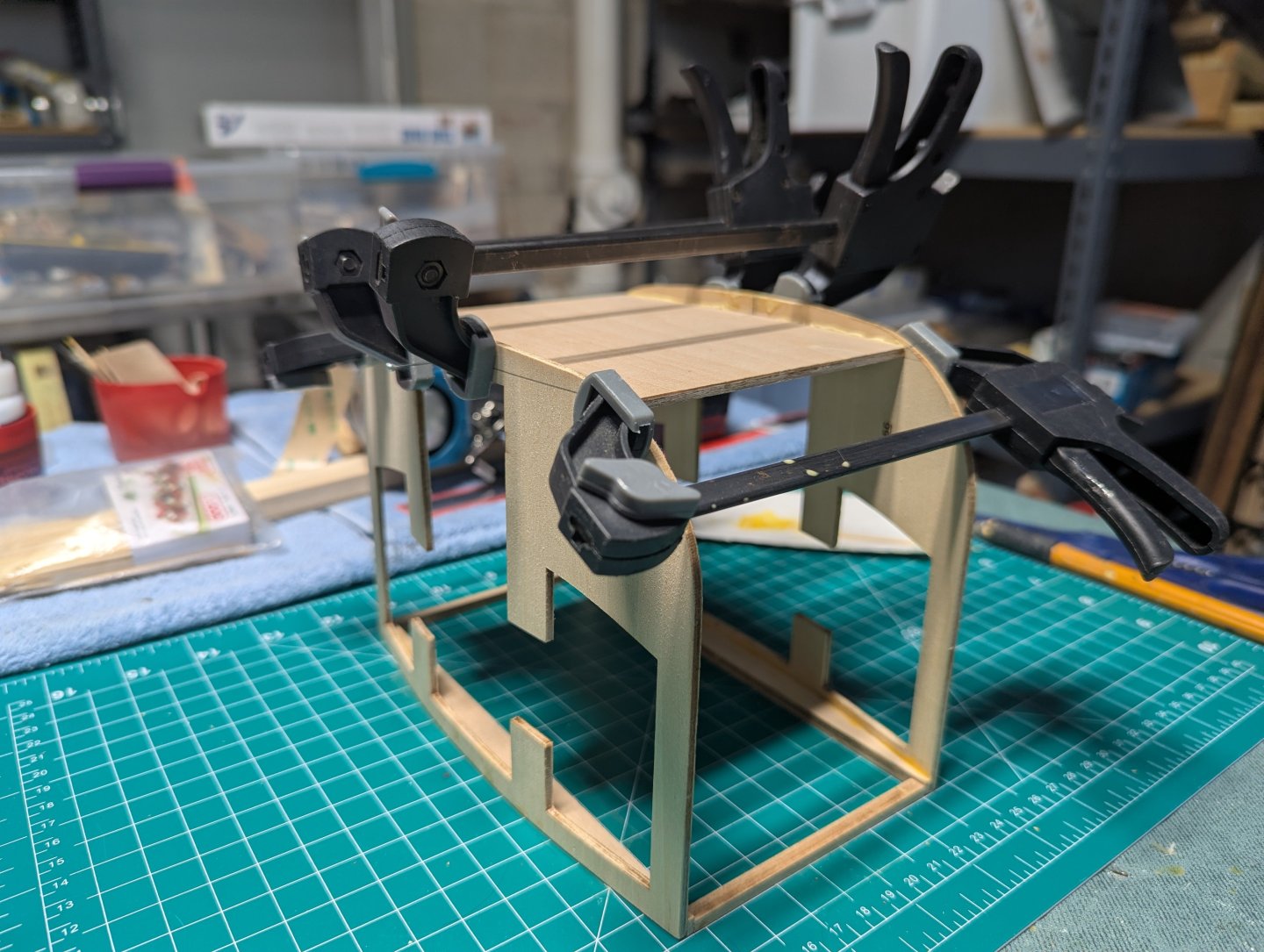
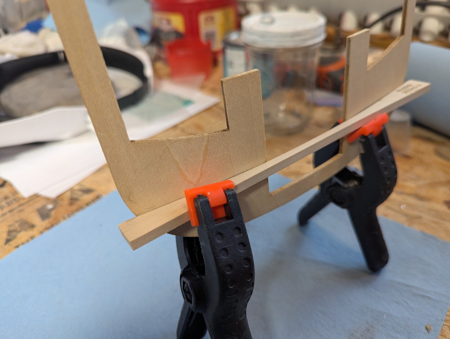
 On to putting the strips around the windows and doors. Keep in mind since it is a curved structure, the strips around the doors and windows will be slightly slanted. In the picture below I only outline a few places, but in reality strips around almost every window and door are slightly slanted. A few pieces of scrap wood some in handy to keep the curved pieces in place while the glue dries. Having said that, once you heat and bend the strip, with wood glue you can just hold the piece for a few minutes and it will adhere very well. Strips are not really required. Not sure if is a flaw with the builder (me) or just all the movement of the pieces in creating the carriage so far, but the tabs that make up the main door and windows for some reason do not line up. They need to be lined up in order to glue the side door piece. A few clamps and some thick wood will line up the tabs, so the door side piece can be easily attached. Once the side piece is glued on, the clamps can be removed and the door side will be perfectly lined up
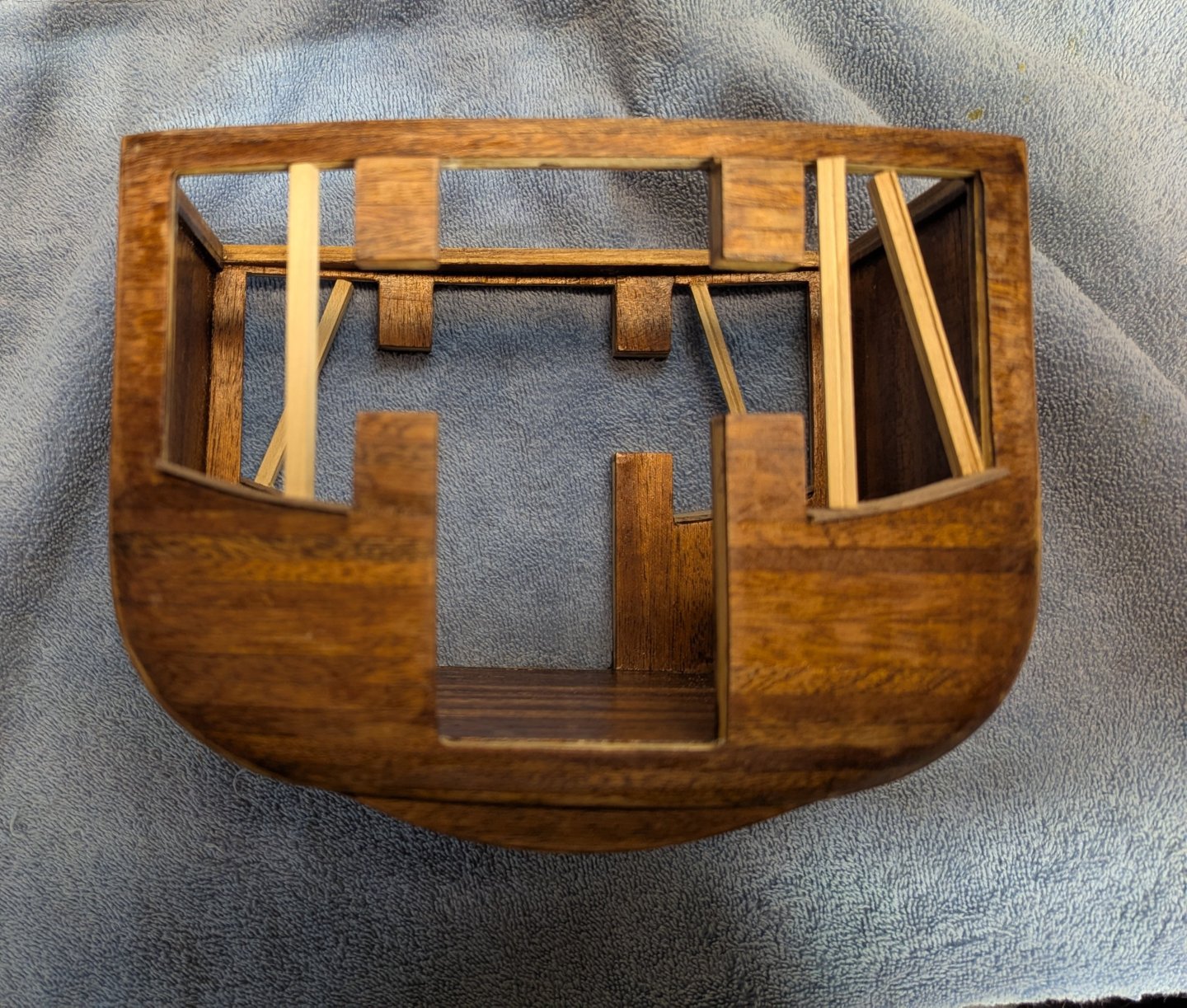

-
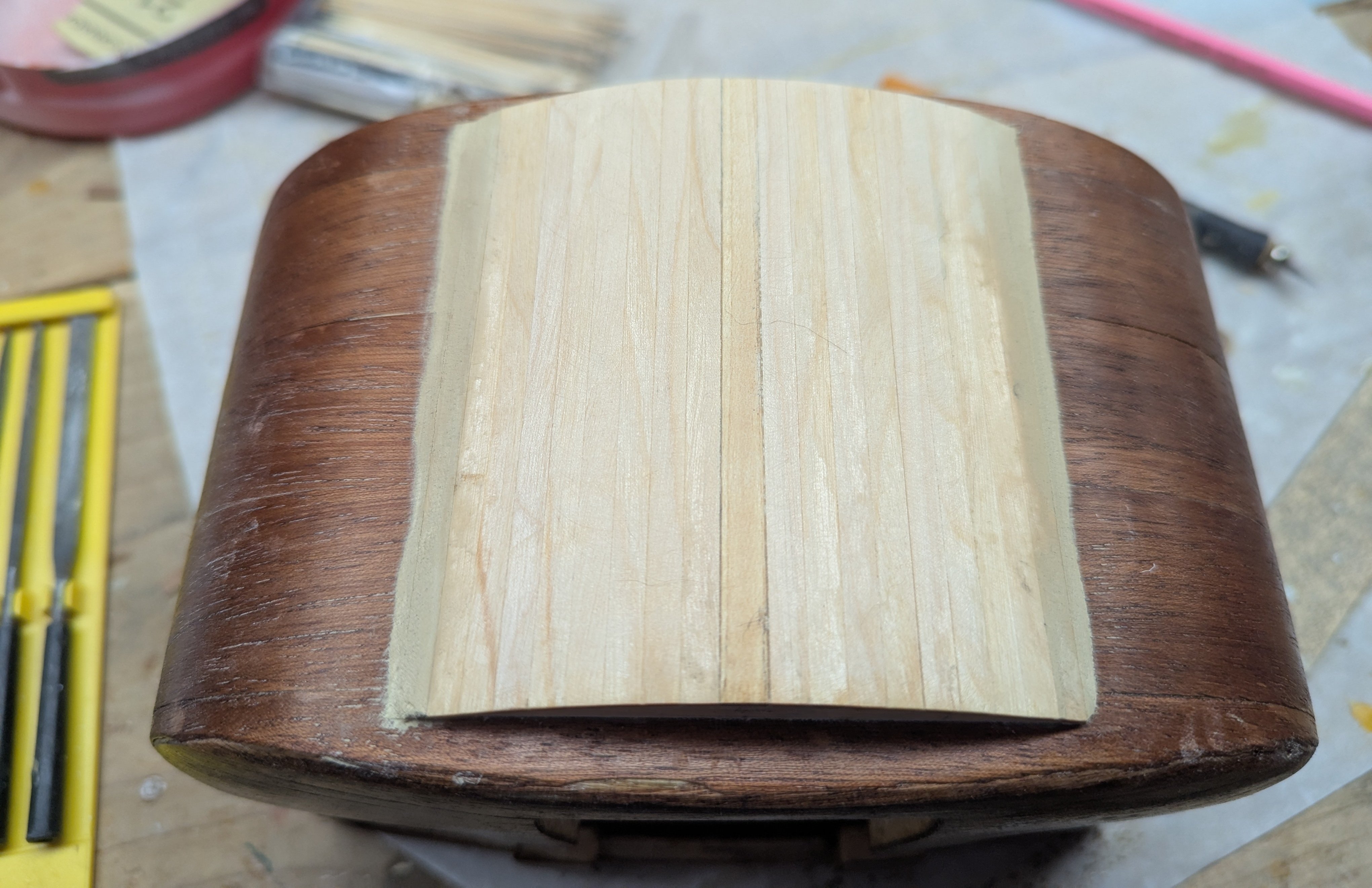
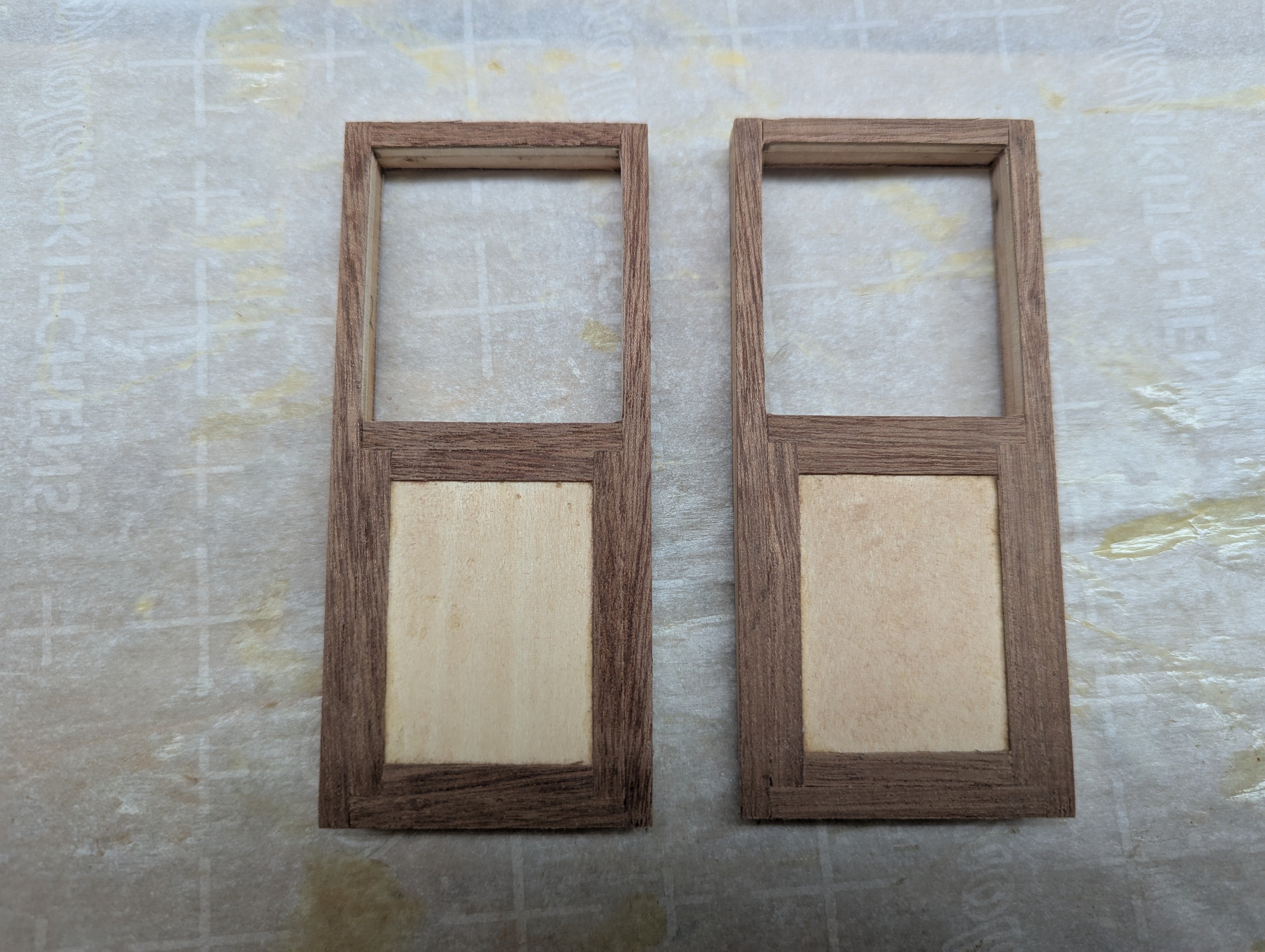
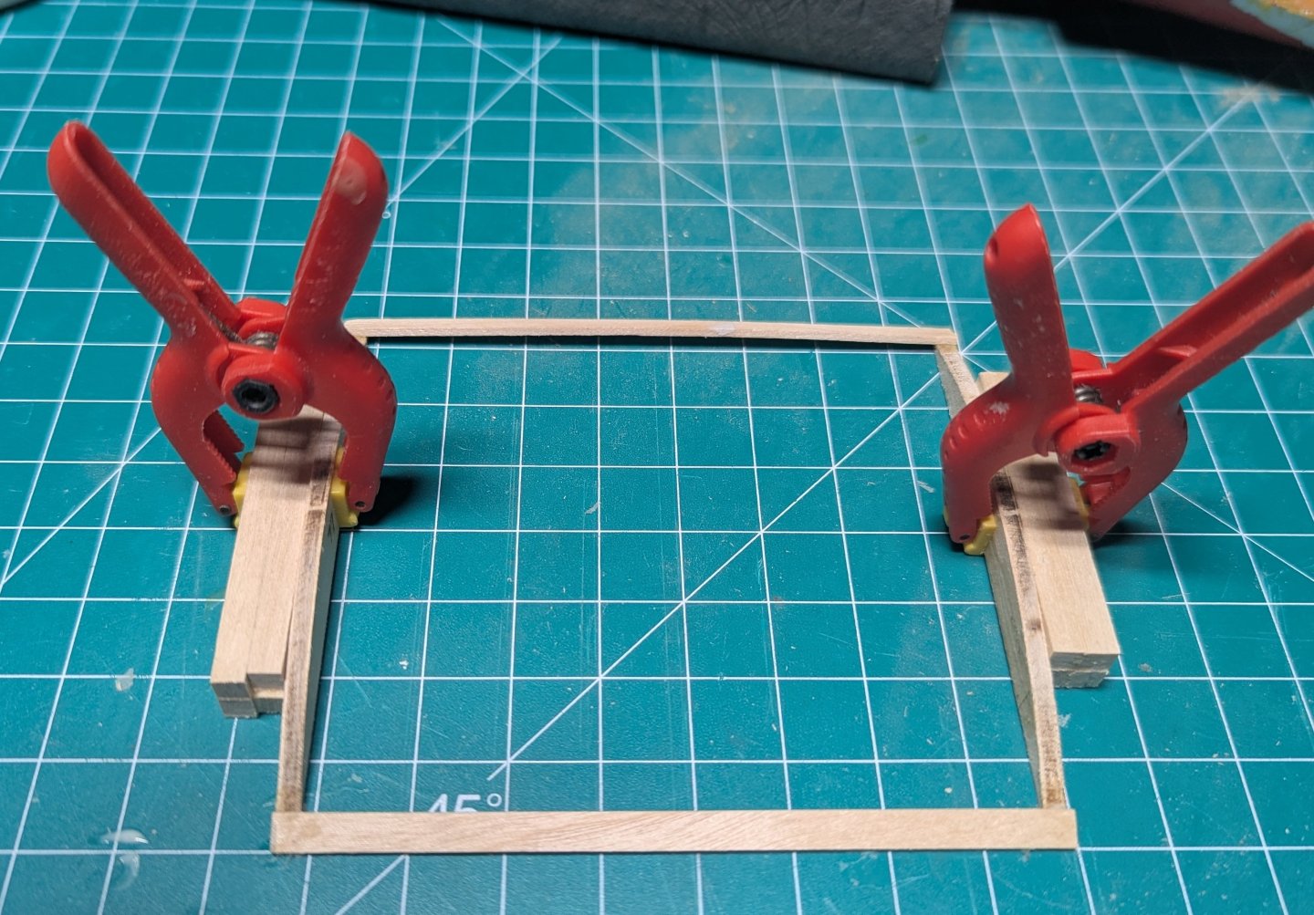
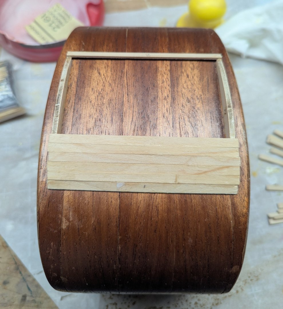
Time to move on to the Double Bottom for the carriage. Starting with the frame, make sure it is really square and glue the two side pieces and front and back planks Position the initial structure on the carriage and glue it down. Again careful measuring to insure it is in the center of the bottom of the carriage. Then begin the planking where each plank is a little longer than needed. It will be easy to clean up the edges later. Not really required, (as these planks will later be covered up), but in order for the top of the planks to fit better together without a small gap, the bottom of each plank was beveled before gluing in place on the structure. Planking in process. Planks were laid from the bottom of each side up to the top. The plank will not exactly come together at the top. There will be a small gap somewhat less then one plank width. In reality, that is OK as again, these planks will be covered up. But in the sense of "why do something easy when you can make it hard", I choose rather then have a small gap, the last couple planks were a little wider as to not have a gap... Not sure why I did that other than I like to punish myself. The end result does look better. Also a little plastic wood filler was added at the first planks to make a smoother transition to the carriage. Side view of the finished Double Bottom And fully covered up... You can see where it did not really make any sense to cover up the plank gaps. Moving on to the doors... A little ahead of the instructions, but I wanted to get them started. First step is beveling them to match the bevel in the carriage Final stage before planking After planking front and back I will add the fine details later.....


-
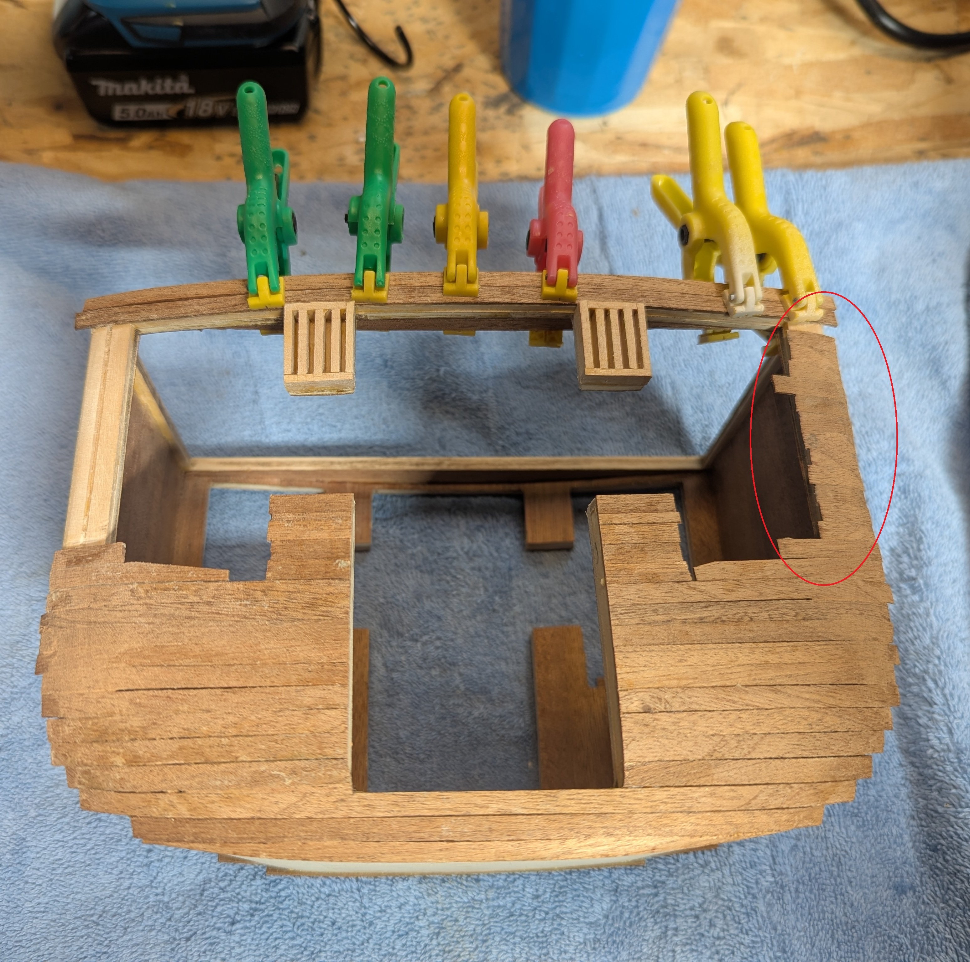
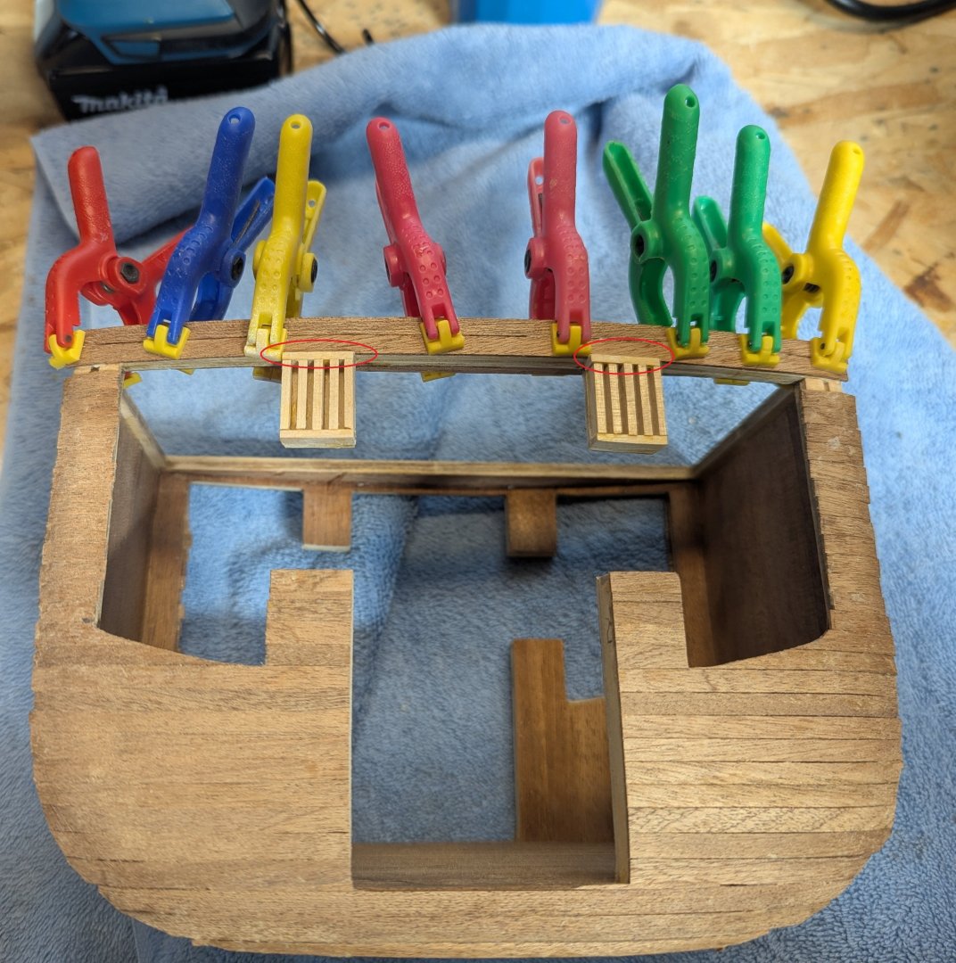
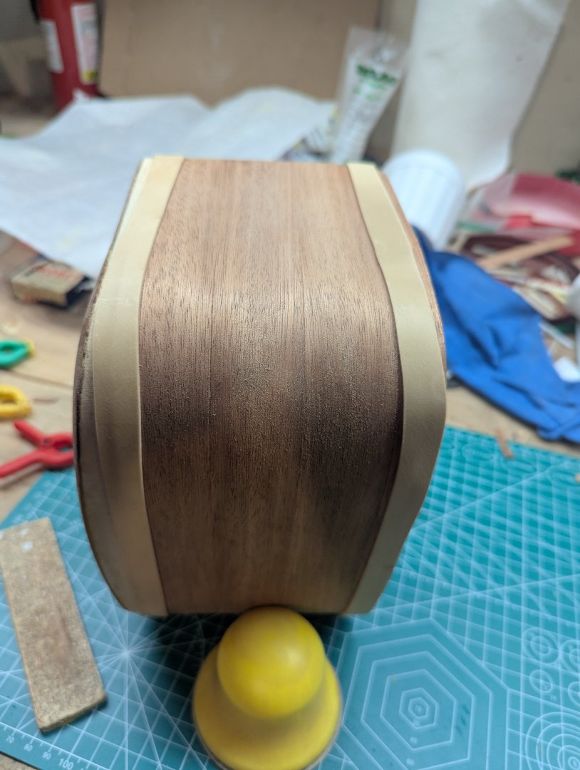
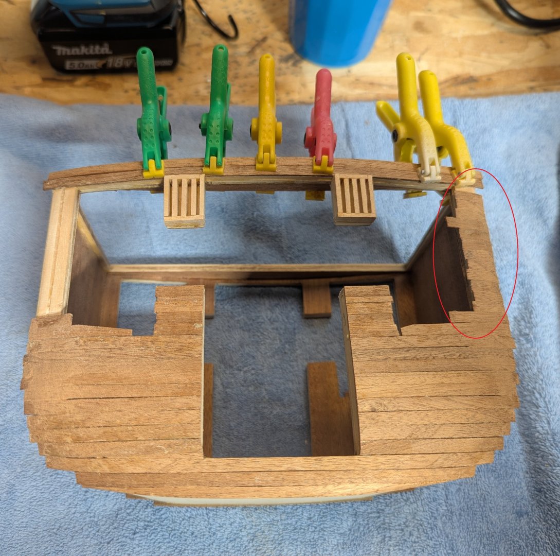
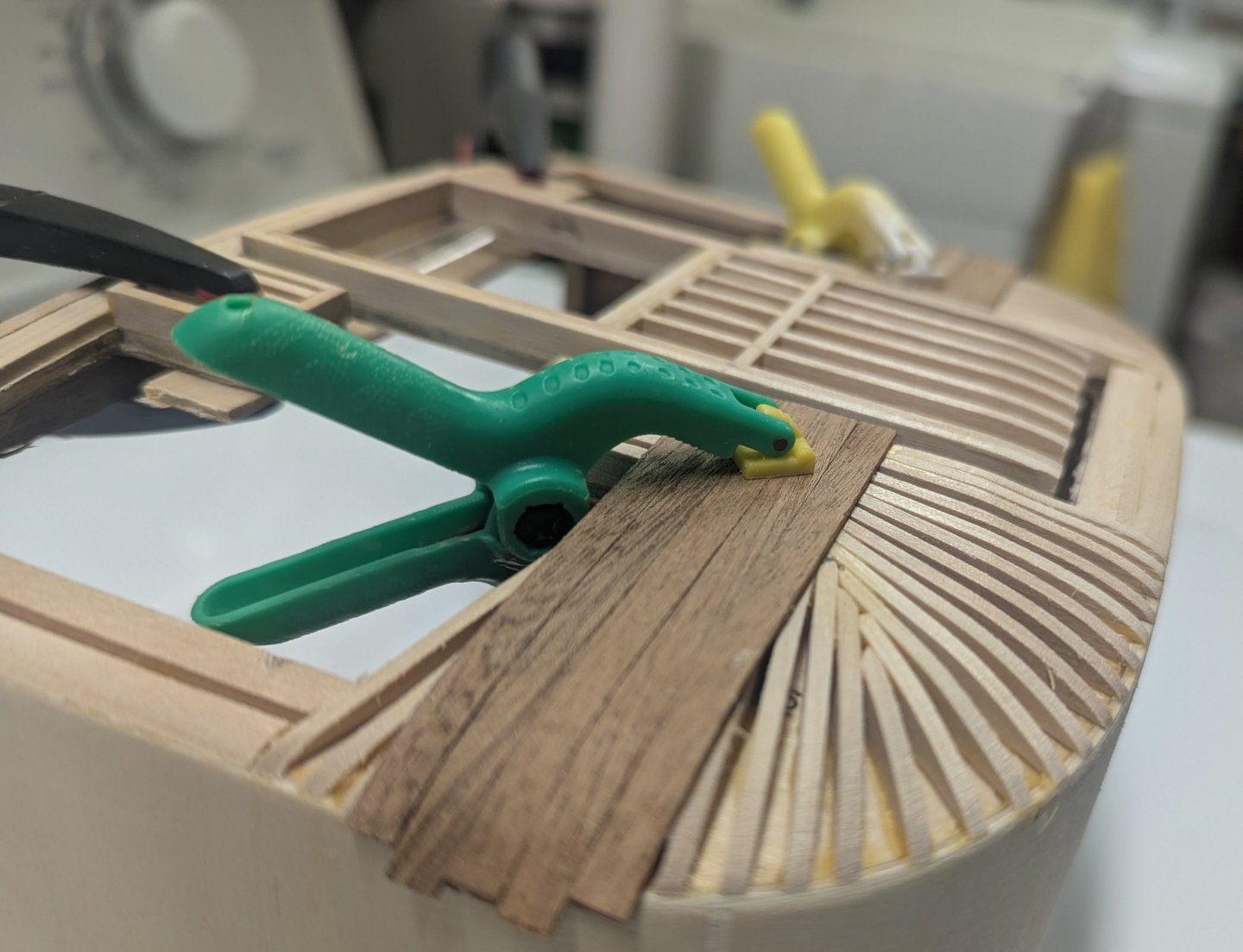
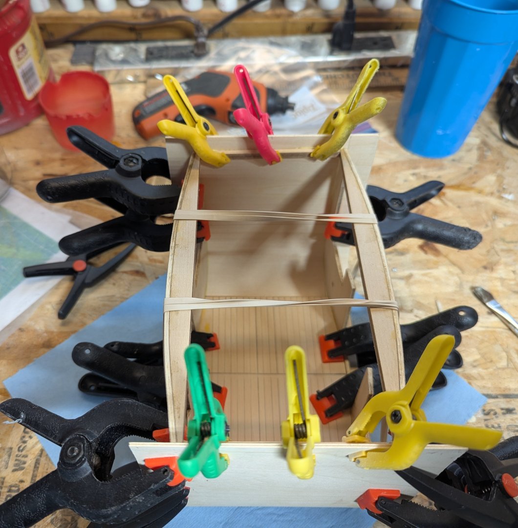
It has been awhile since I last updated. Summer has hit and all sorts of distractions come up the lead me away from the building. This stagecoach will get completed, it will just take awhile. Working my way across the side and up to the top with the planking. The section circled in red, according to the instructions, should be planked with vertical planks. Not sure it matters in the end, but I liked keeping the planking the same directions as the lower planks. These four sections were planked with horizontal planks, With planking almost complete, I noticed a potential (shall we say) improvement. According to the directions, the areas circled below have either a horizontal plank (as I have) or the five vertical planks go all the way to the top. Either way there is a potential issue/improvement to me made. Looking ahead in the instructions there will be a horizontal plank going across the top to these two windows with a break at these two spots. I like the idea of the look of a continual plank, so the top 1.5mm will need to be carved out. Below shows the top 1.5mm trimmed off the top of these sections. Room for the plank to be added later. Other than that, planking both sides of the carriage is pretty straight foreword. Once planked, the sides need to be trimmed with a knife and sanded smooth. Final planked carriage ready for stain and varnish. Next need to start coving the front, back, and bottom of the carriage. Starting in the middle with the first strip. A couple of large rubber bands really comes in handy here to hold the strip down while the glue dries. Slowly working your way out with other strips. The outside strips will hang over the edge and need to be trimmed Below you can see the strip hanging over the edge. Once the glue is dry, using a sharp x-acto knife, the strip is easily trimmed. After trimming. Edge between side and front/back,bottom edges does not need to be exact as a strip of wood will eventually over up the seam. Final shot from the top. At this point I plan to put about four coats of rub-on poly to help protect the carriage. In the end there will be more coats of the rub-on poly as more details are added, but for now four coats is plenty. In hind sight, I would defiantly be faster to use a foam brush and just paint on normal polyurethan rather then rub-on poly as rub-on poly is really thin and takes a lot of coats. I have a feeling when it comes time for more polyurethan I may just brush it on rather then use the rub-on poly. Having said that, rub-on poly lays down a really smooth coat with no worry about runs. We'll see what I feel like when that time comes.


-
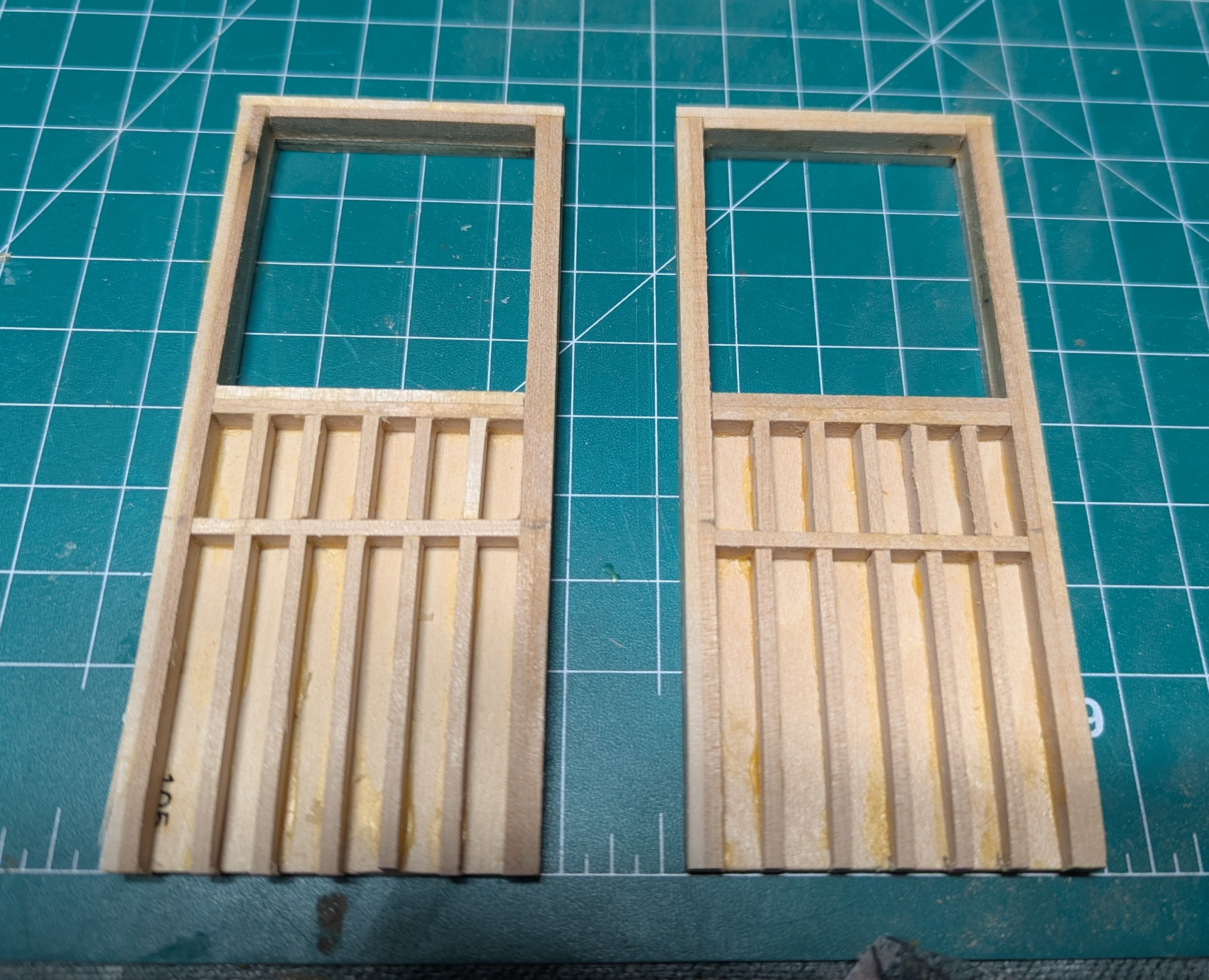
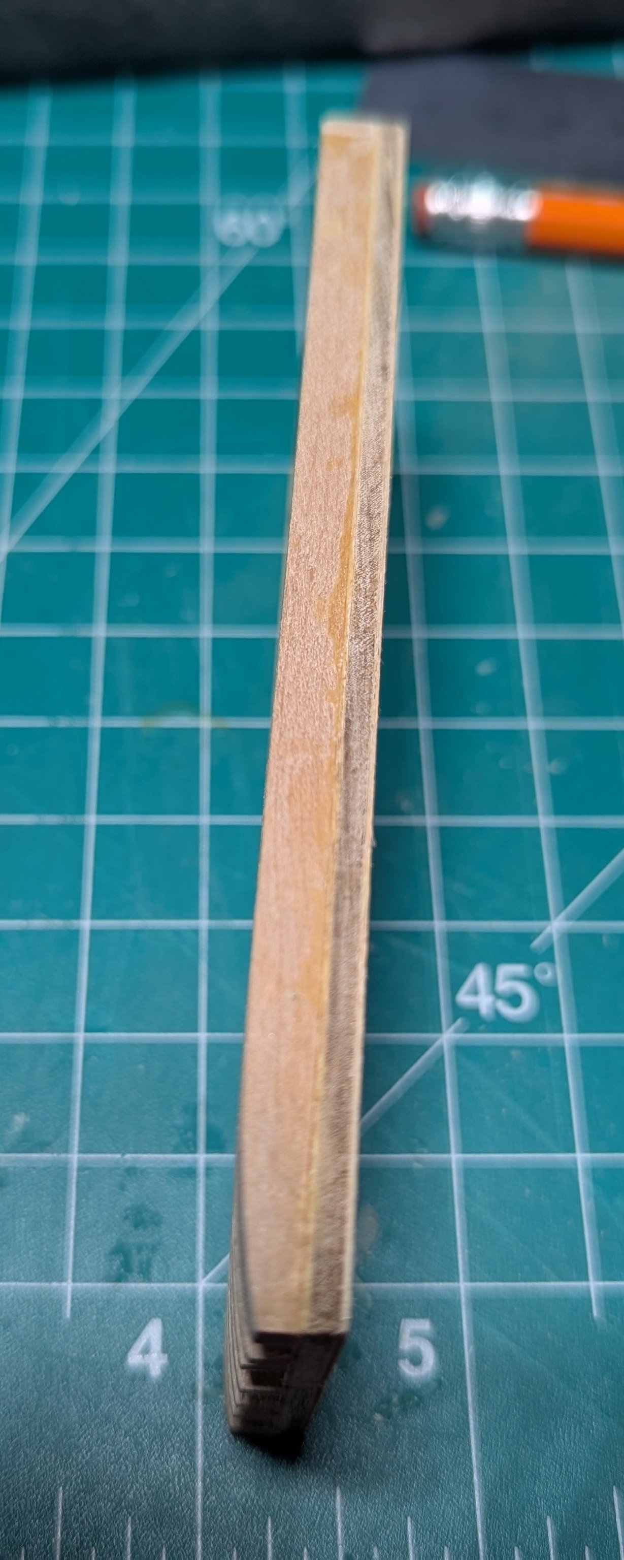
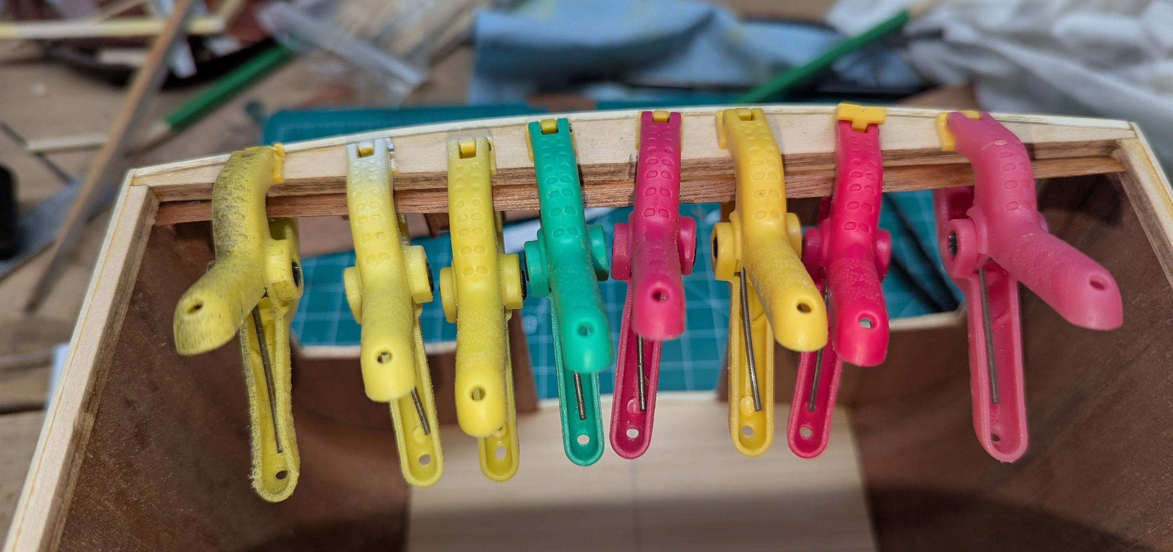
Starting to add the external planking on the carriage. Instructions calls to use CA glue due to the fact (I think) that the carriage is curved and easier to lay the planks. I like using normal wood glue. I used a side of a soldering iron to bend the end of each plank (to match the curve in the carriage) and then using wood glue and a large rubber band glued the piece in place. Laying planks on both sides of the carriage, wood glue does dry fast enough so that as you glue each piece, by the time you get to the 4th piece, the 1st piece is dry. So you can just keep going around the carriage laying each piece and not have to stop waiting for the glue to dry. I would highly recommend getting some sort of band to hold the planks in place while the glue dries. Really helps keeping the curved down for the glue to set up Instructions do not call at this time to do it, but I thought it would be a good time to sand down the doors to match the curve in the carriage. Instructions call to do this in a later step after the carriage has been planked. Actually I probably should have done this before I starting the external planking. Anyway, with some 2 sided tape, a couple spare planks, and some clamps you are able to hold the door pretty close to where it will be in it's final position. From there you can see the curve of the carriage and sand down the door to match the curve. Basically looks at what needs to be sanded, remove the door, sand it some and then stick it back in the carriage and look at the curve. Only take a couple attempts to get the curve in the door to match the carriage. Not a real good shot, but you can see the curve in the door matching the curve in the carriage. Before I do the final planking on the door, I may have to do some more fine tuning, but this is pretty close. Status at the end of the day. Again, both sides of the carriage are planked at the same time. Working my way to the bottom. Once complete, I will work my way up to the top


-
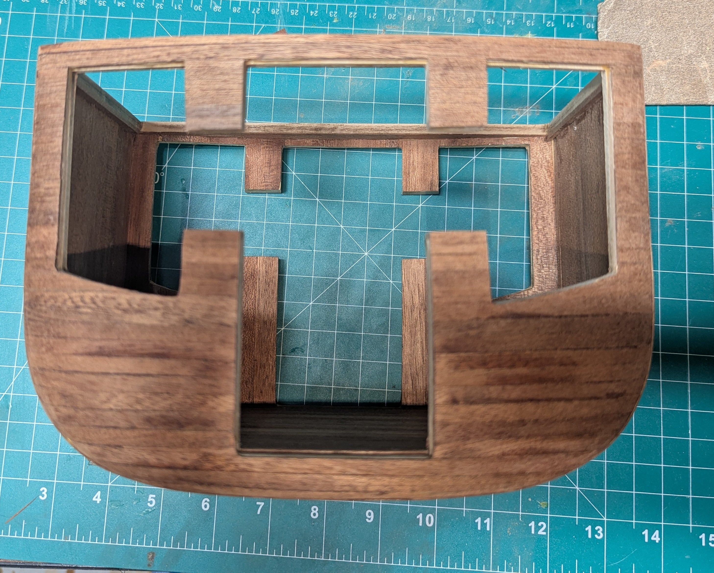
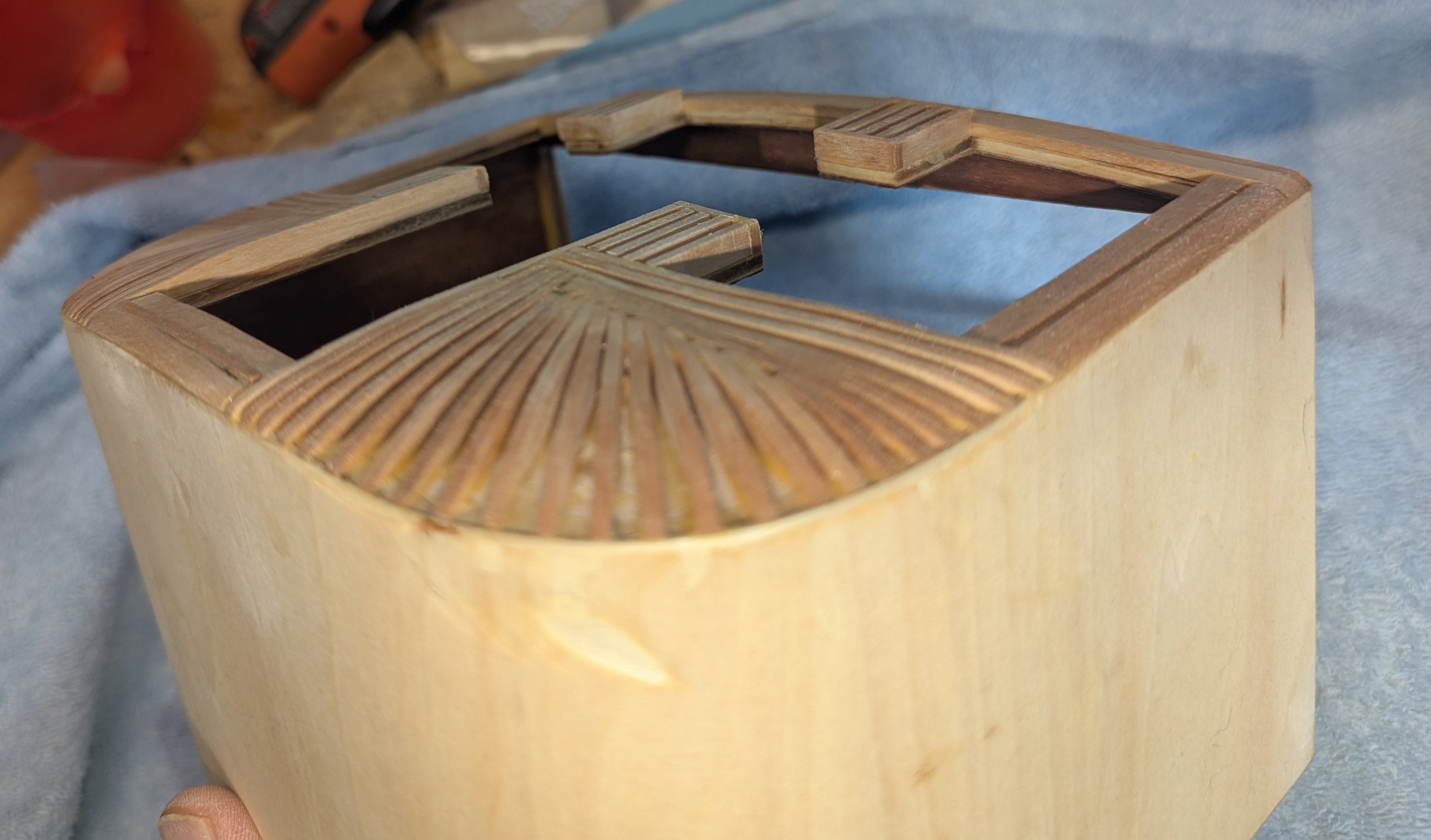
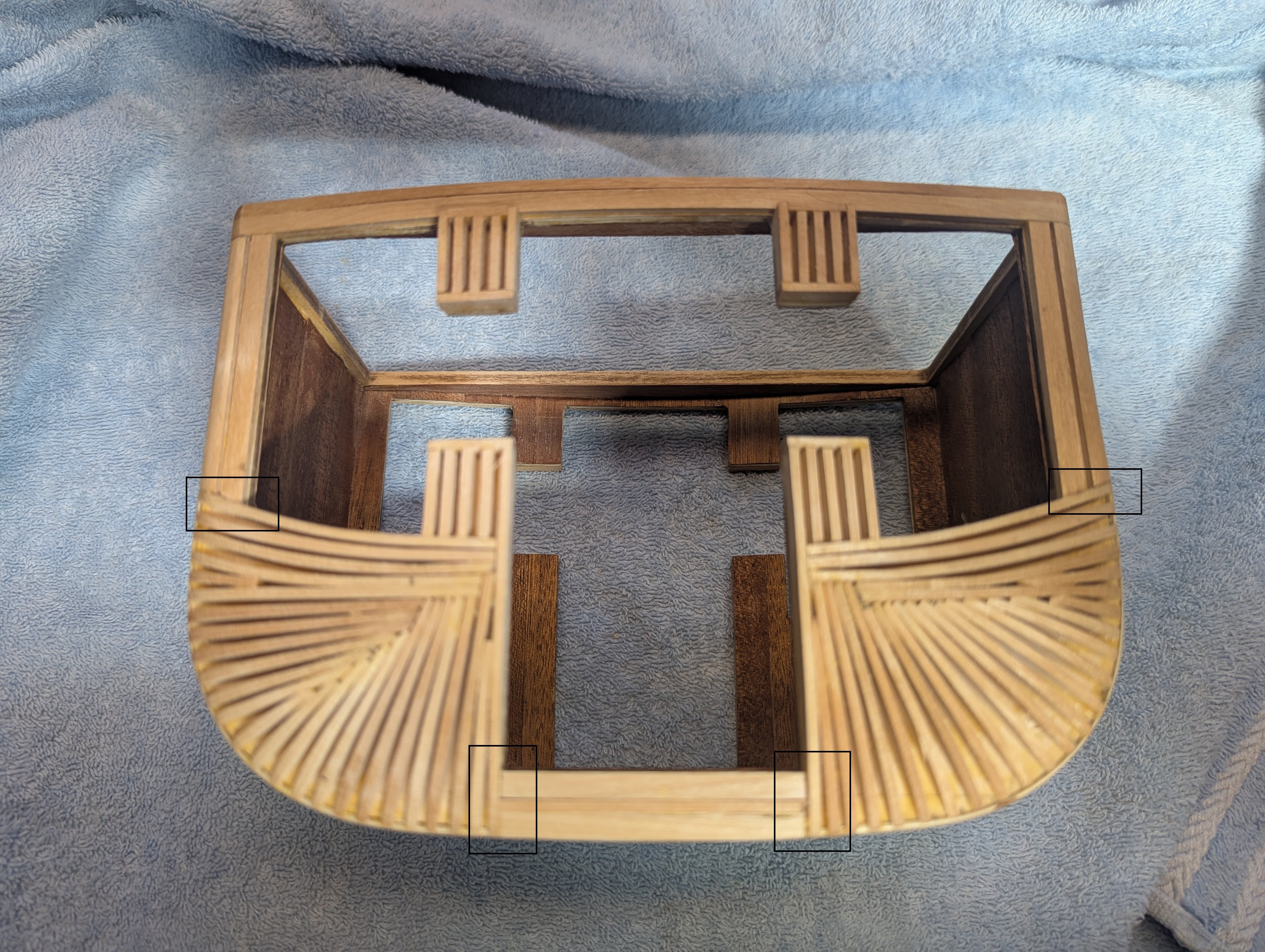
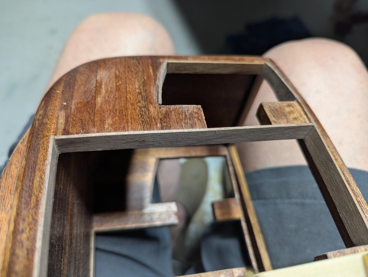
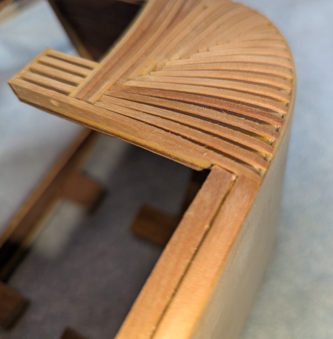
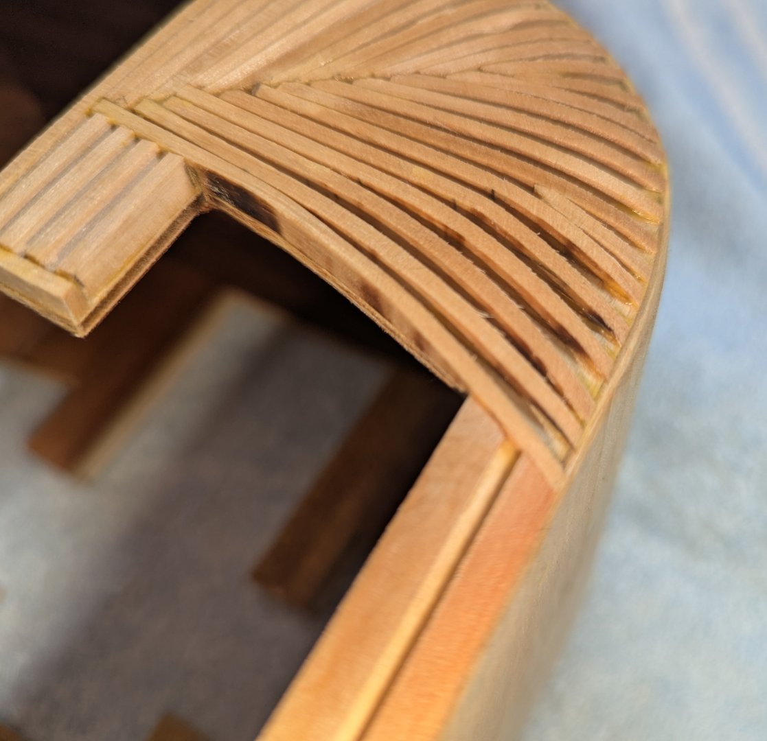
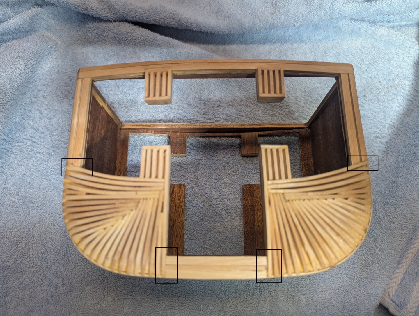
On to trimming and shaping the four sides..... I mentioned above that laying the strips got old very fast.... but sanding and shaping these same strips really got old fast. This step kicks up a lot of dust. I recommend wearing a mask and if the weather is nice outside, do this trimming outside. Main idea after the strips are trimmed is to sand them from top to bottom forming a somewhat convex shape. Very little is trimmed off from the top of the strips to when almost all of the strips are sanded off at the bottom. Below is on of the two finished sides. Pay special attention to the four areas marked with black boxes. Since the finishing strips will lay across these initial strips there needs to be a smooth transition between the strips and the side walls. Pardon my photos,,, I seemed to have moved the camera with them as some of them are out of focus.. I will try to be more careful in the future. Below are some close ups of the four transition sections I mentioned above. You will also note the convex shape of these walls

-
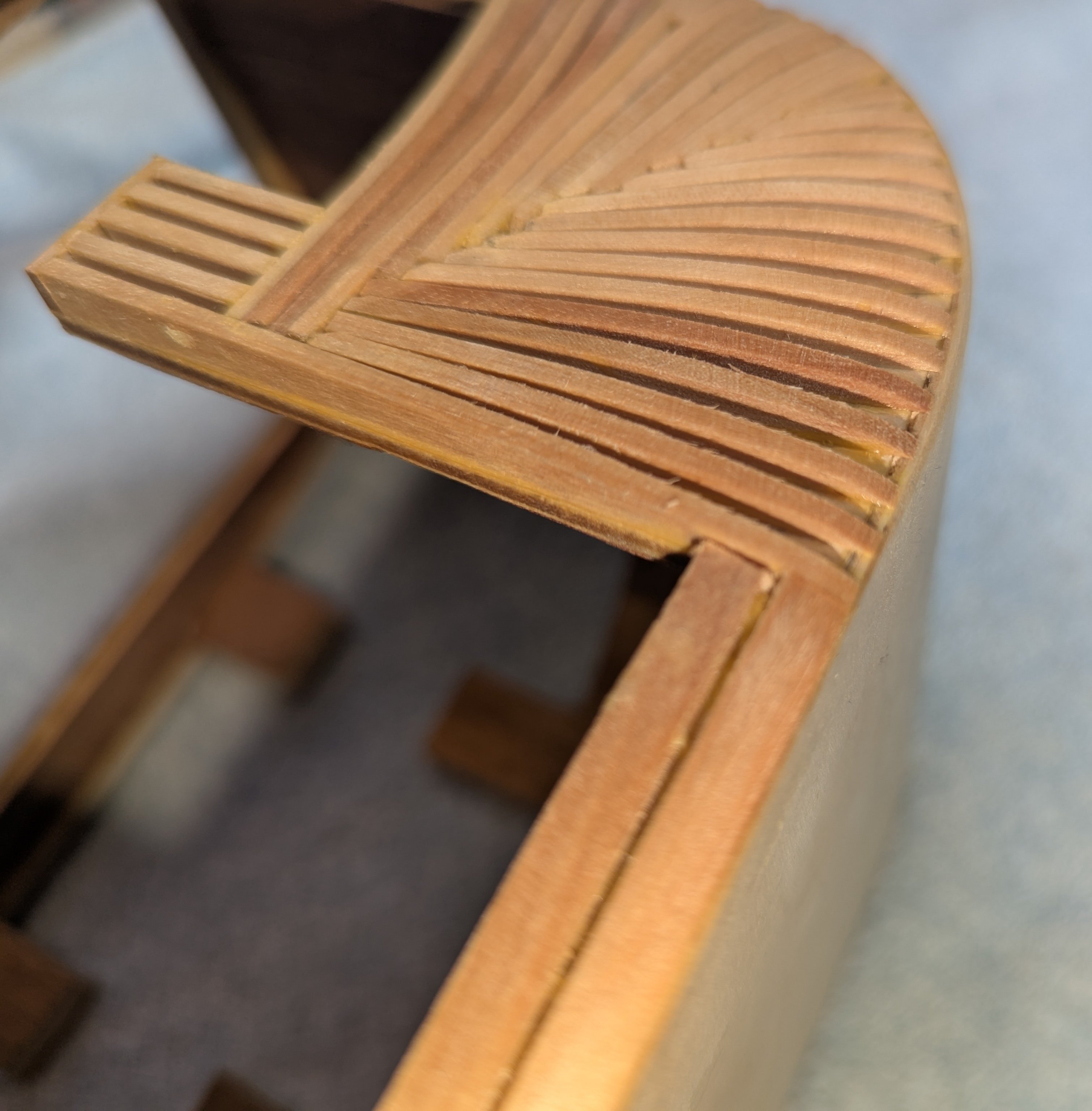
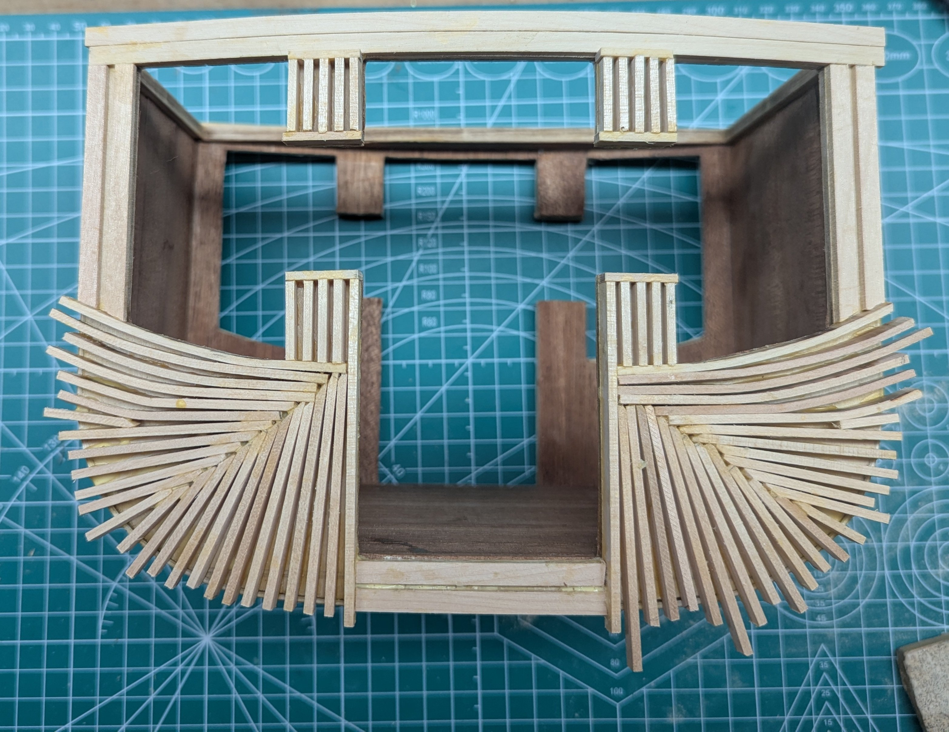
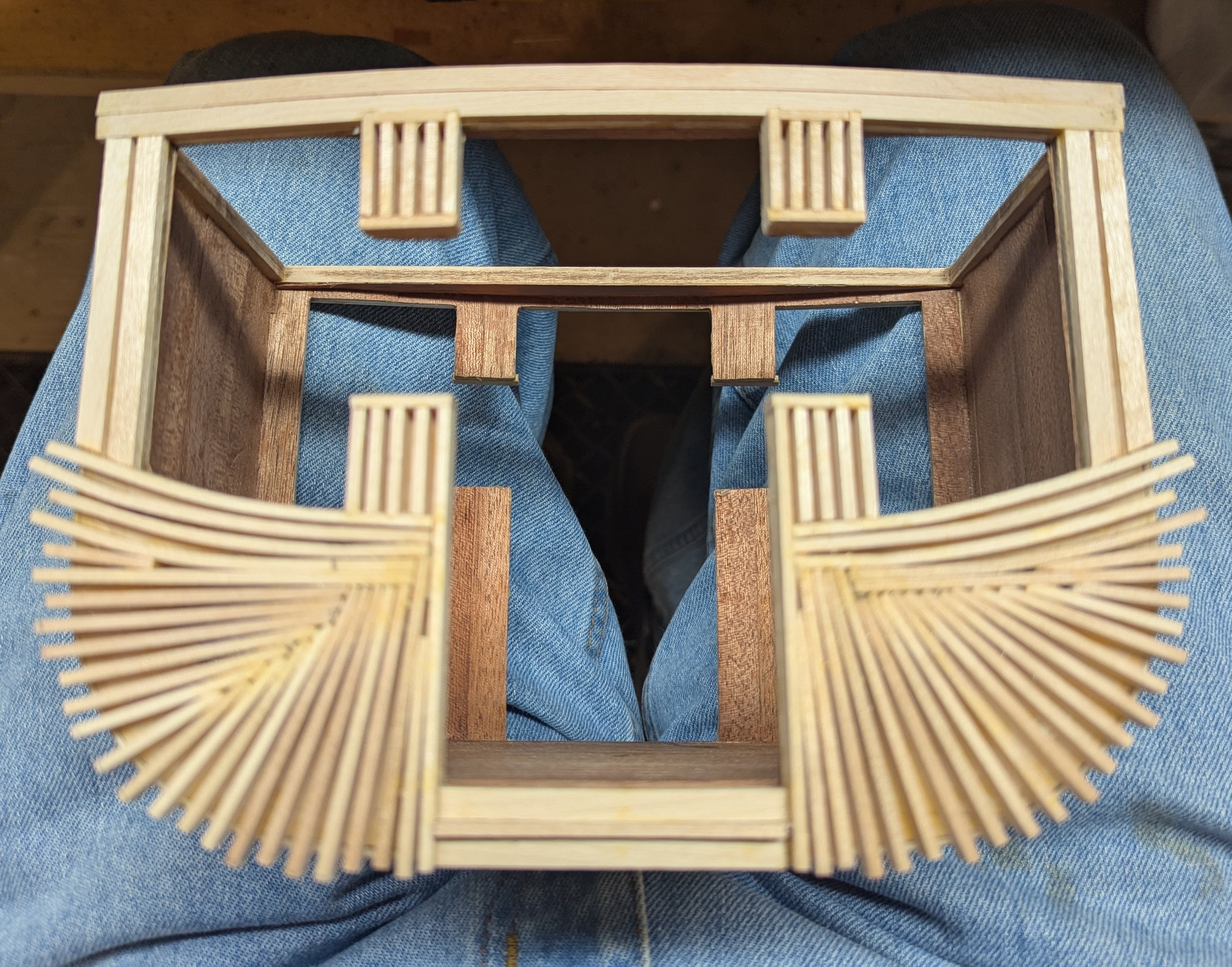
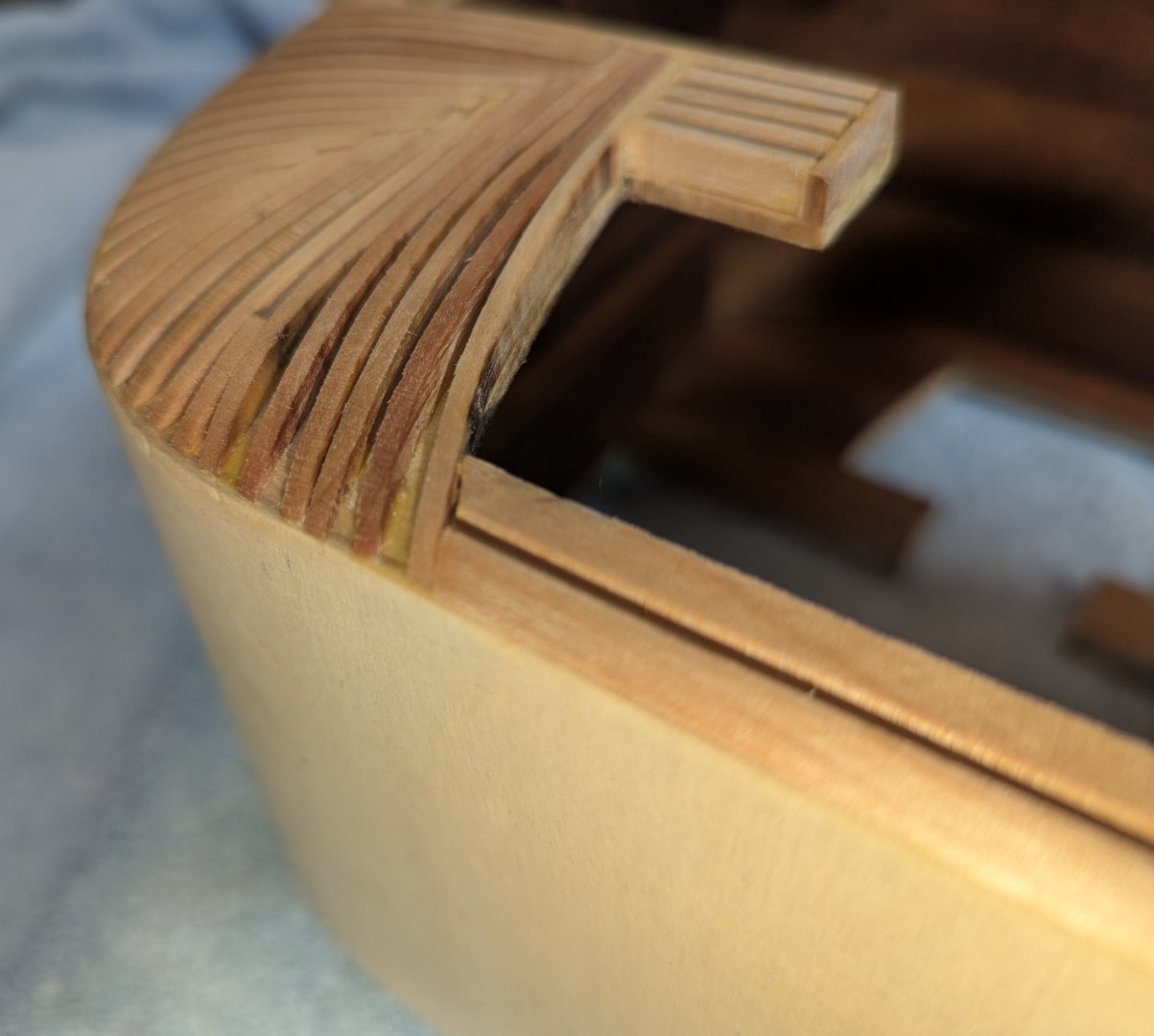
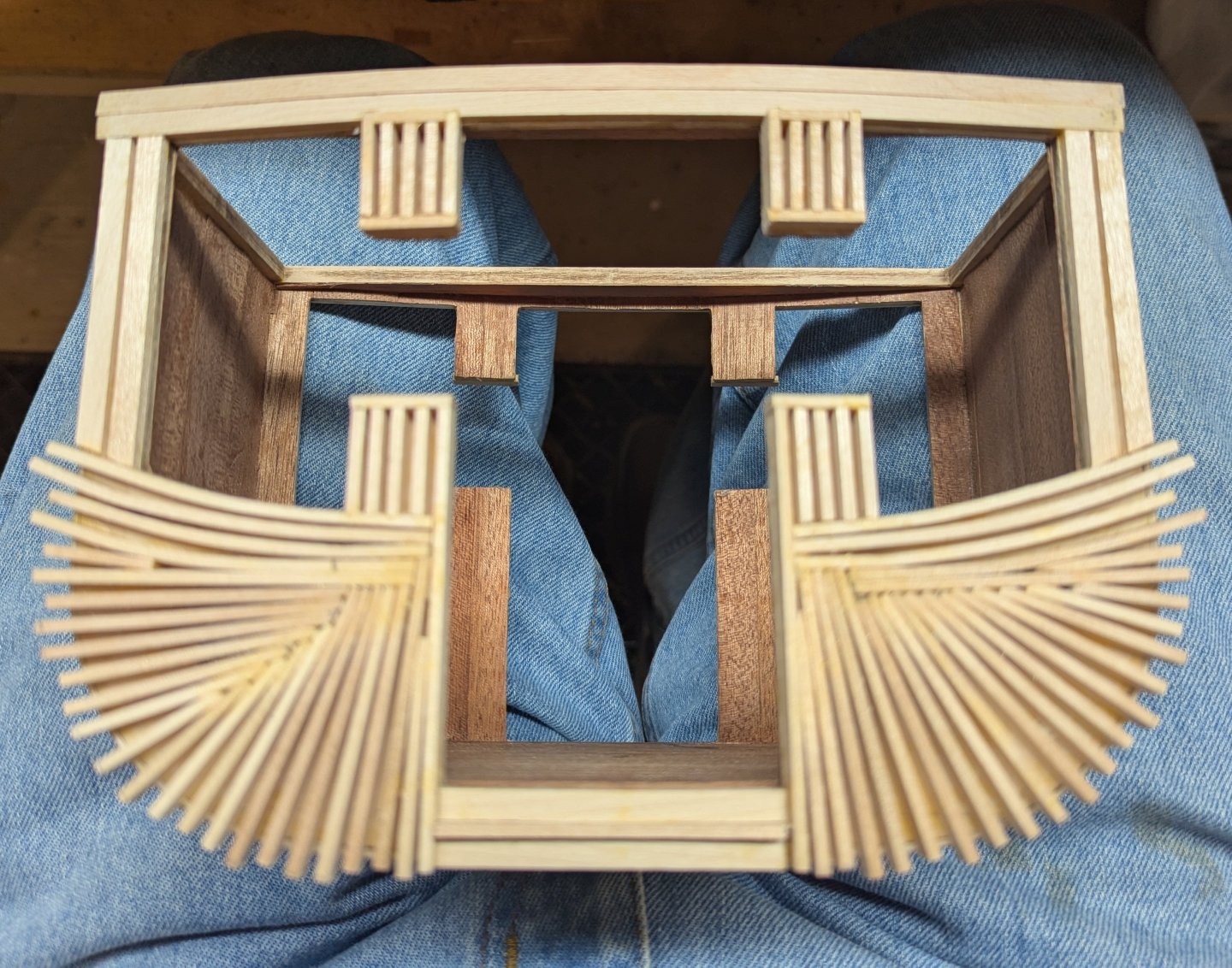
With the inside lined, time to add the external strips that will form the curved edge. Looks like I jiggled the camera when I took this shot. Basically the strips around the sides are laid flat and the ones on the lower part of the carriage are laid on edge Now starts the process of cutting the small strips that will eventually form the curved edge. Not much to show of the process other than to say cutting the strips and laying them on edge got old really fast. Below is the completed left side. Don't need to make it too neat at almost all of it will get sanded off And the completed right side. Again, are really tedious task. Before the sanding, others have mentioned to make up the two doors so when sanding the curve there is a smooth transition between the walls and the doors. Making the door will be the next step.


-
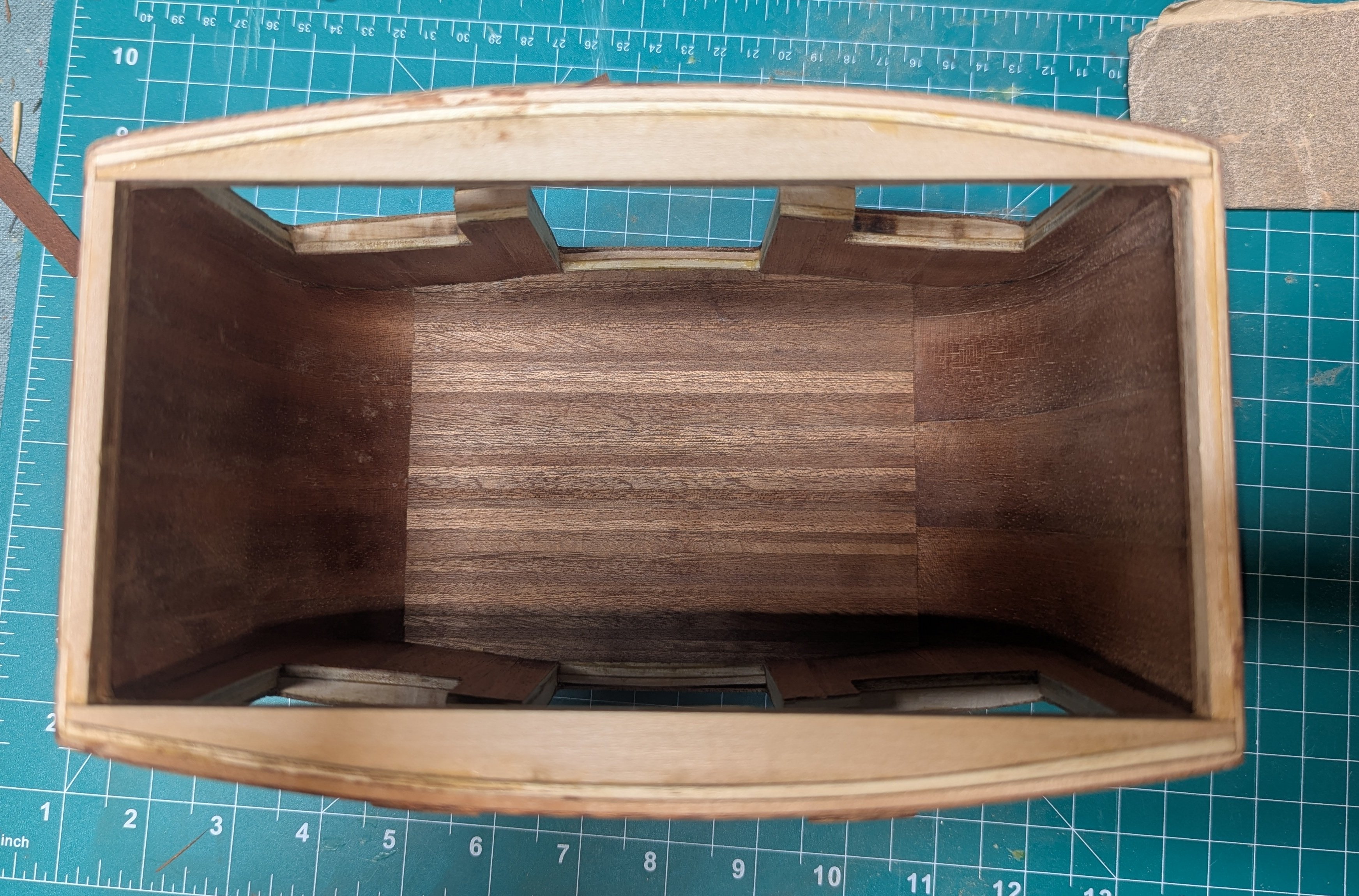
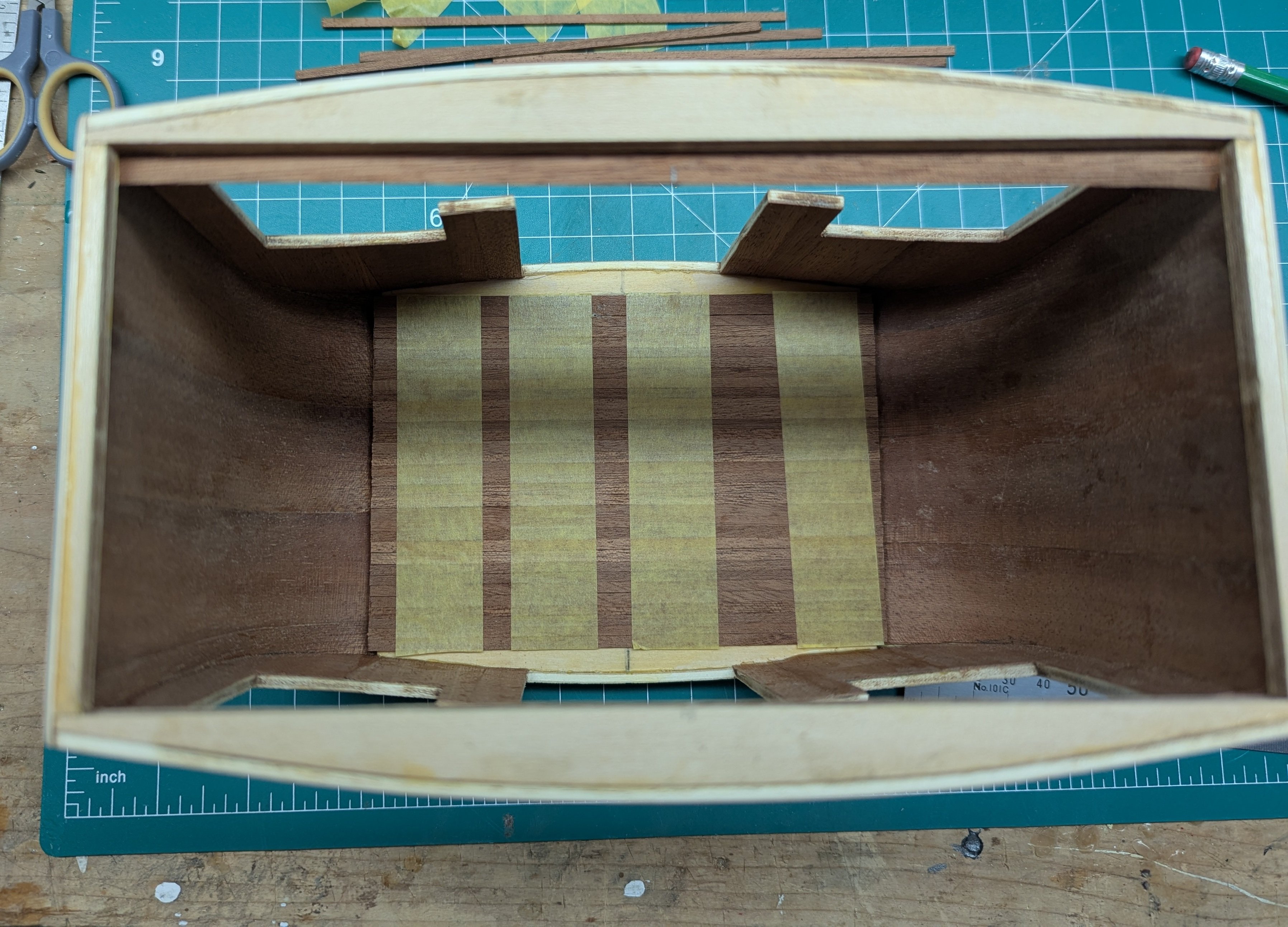
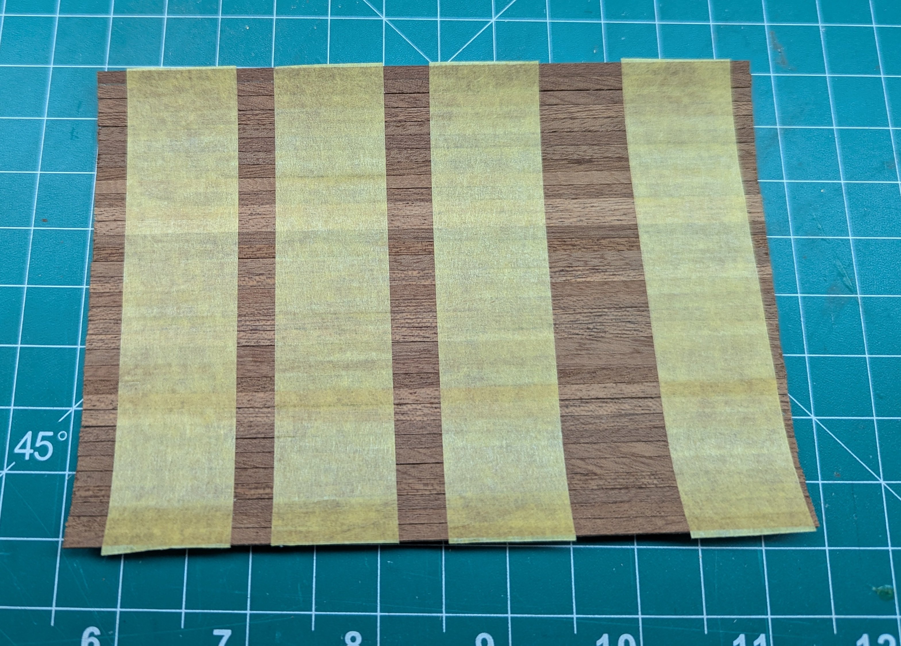
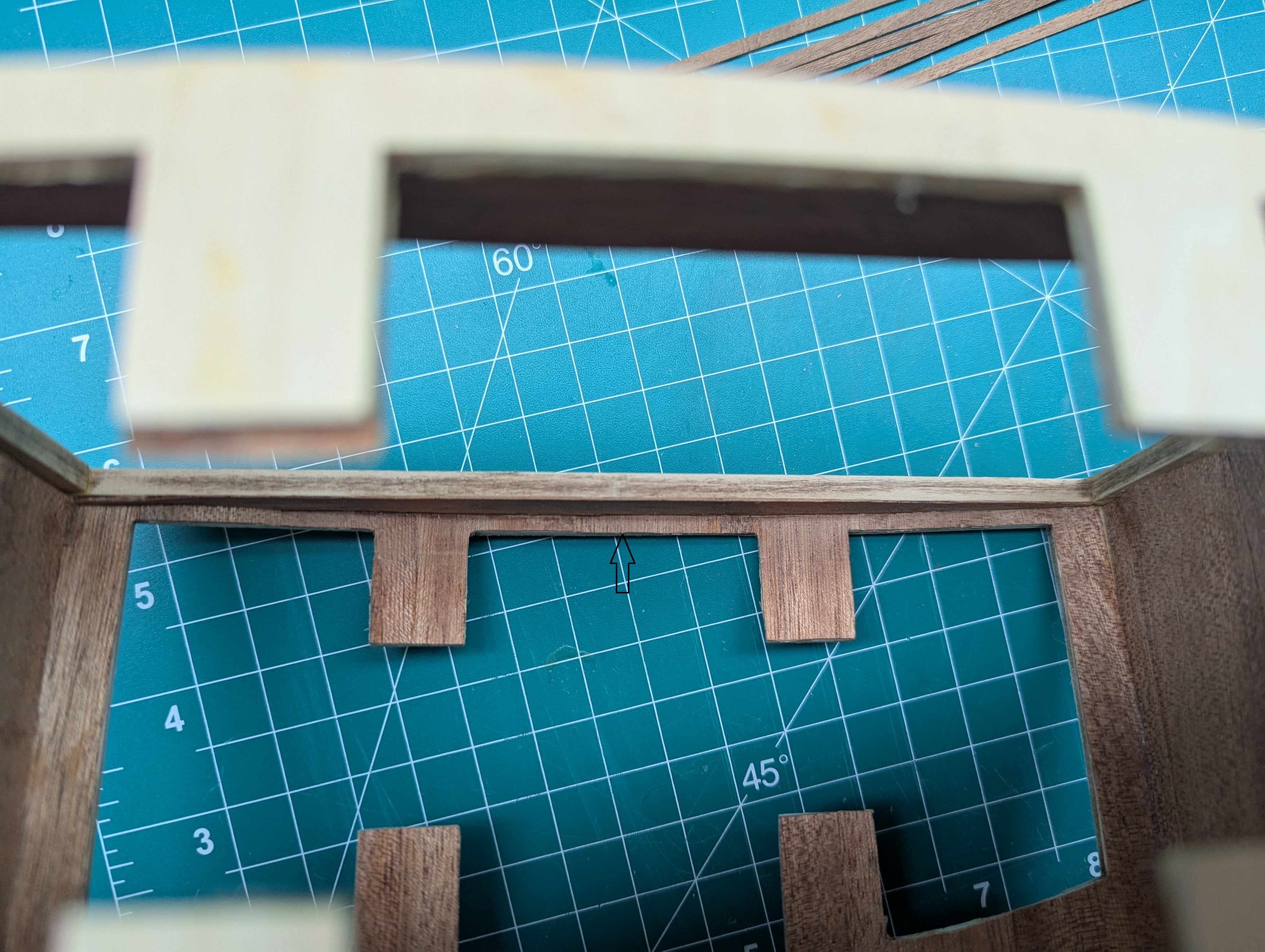
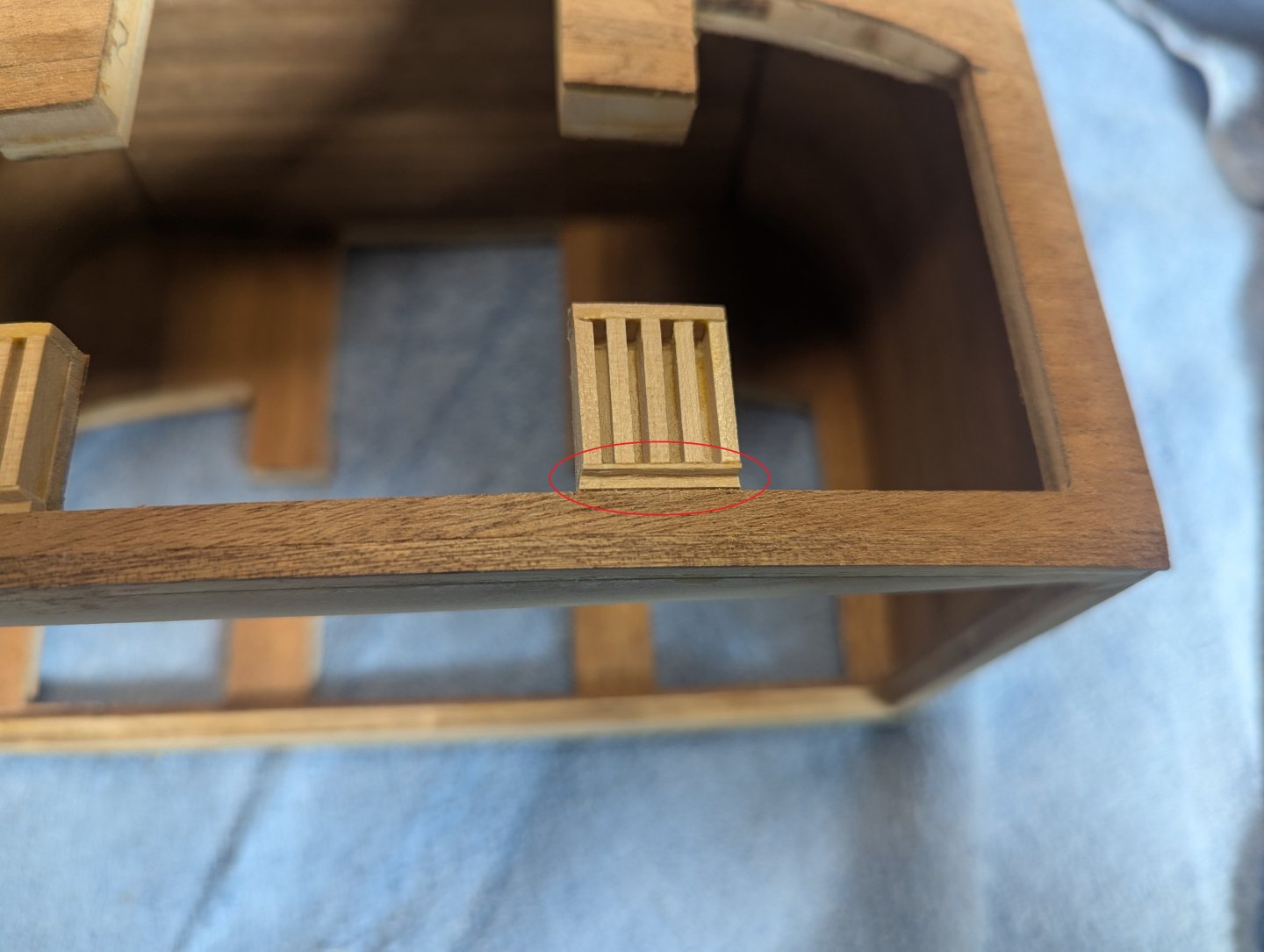
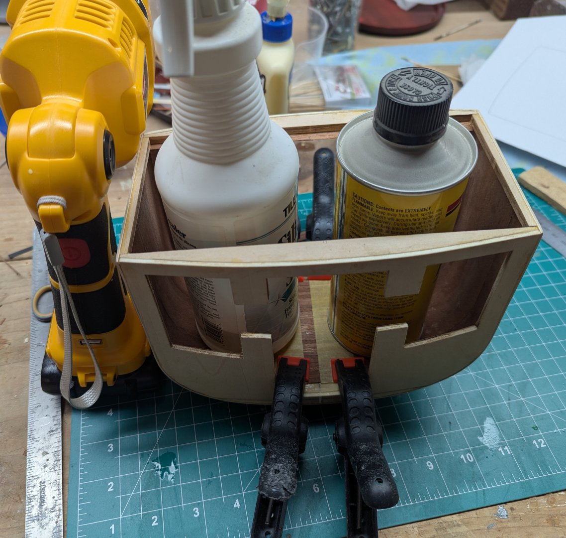
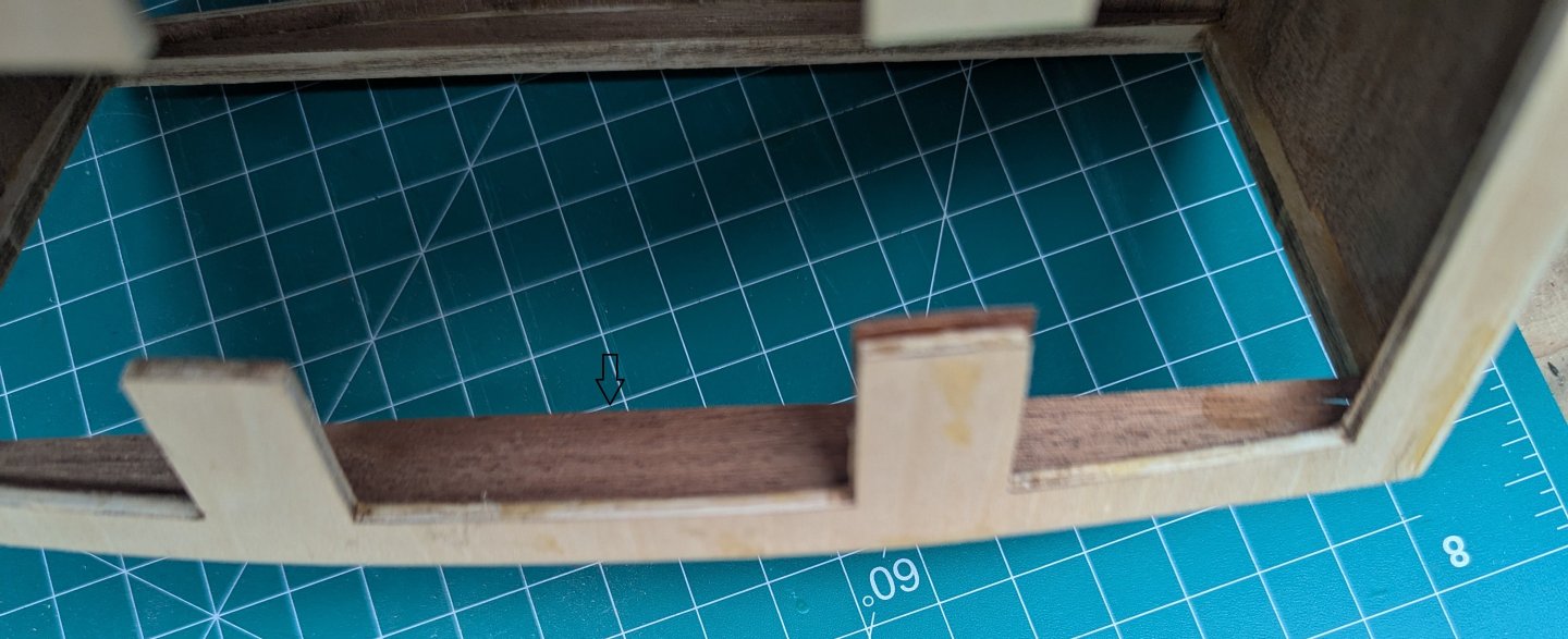
Once the clips come off and excess trimmed, the inside is done except for the floor. Take you time with the thin rim around the top of the carriage (marked with black arrow). As you work your way around the top of the carriage, this area is so thin, when cutting across the grain it is very easy to split the very small thin piece of wood. Expect to have some bad words as you go around the top. Other than that, the rest of the carriage is pretty straight forward. Finished and trimmed top edge On to the floor. As mentioned earlier, the best/easiest way to lay the floor is to do it before you attach the walls. If you are like me and did not think that far ahead, the 2nd best way is to assemble most of the floor outside the carriage. I started with the outline of the floor on a sheet of paper. This was to get the general size of the floor and lay out the panels. All the panels are full length except for the two panels by each door. Those will take trimming. Once the panels are all laid out flat and lined up, slip out the paper and you will have the layout of the floor. Make sure the panels a lined up and close together. Tape them to keep them together. I would recommend some not very sticky tape such as painters tape. Does not take much to hold these planks together. At this point you can lift up the entire floor and dry fit it in the carriage. The final four panels by each door will be shaped and glued in once the floor is in. Below, floor is dry fit into the carriage. Once you see how the floor will fit into the carriage, line the floor with glue and lay the flooring done. Add whatever you have to weight it down. Note the tape is still attached at this time. Once the glue dries, 99% of your floor is complete and way easier then laying one plank at a time in the carriage. Only thing remaining is the four trimmed panels by the doors.. At this point remove the tape. It take some patience and a steady hand but these pieces are easily trimmed and glued into place. These trimmed pieces will be similar to below.


-
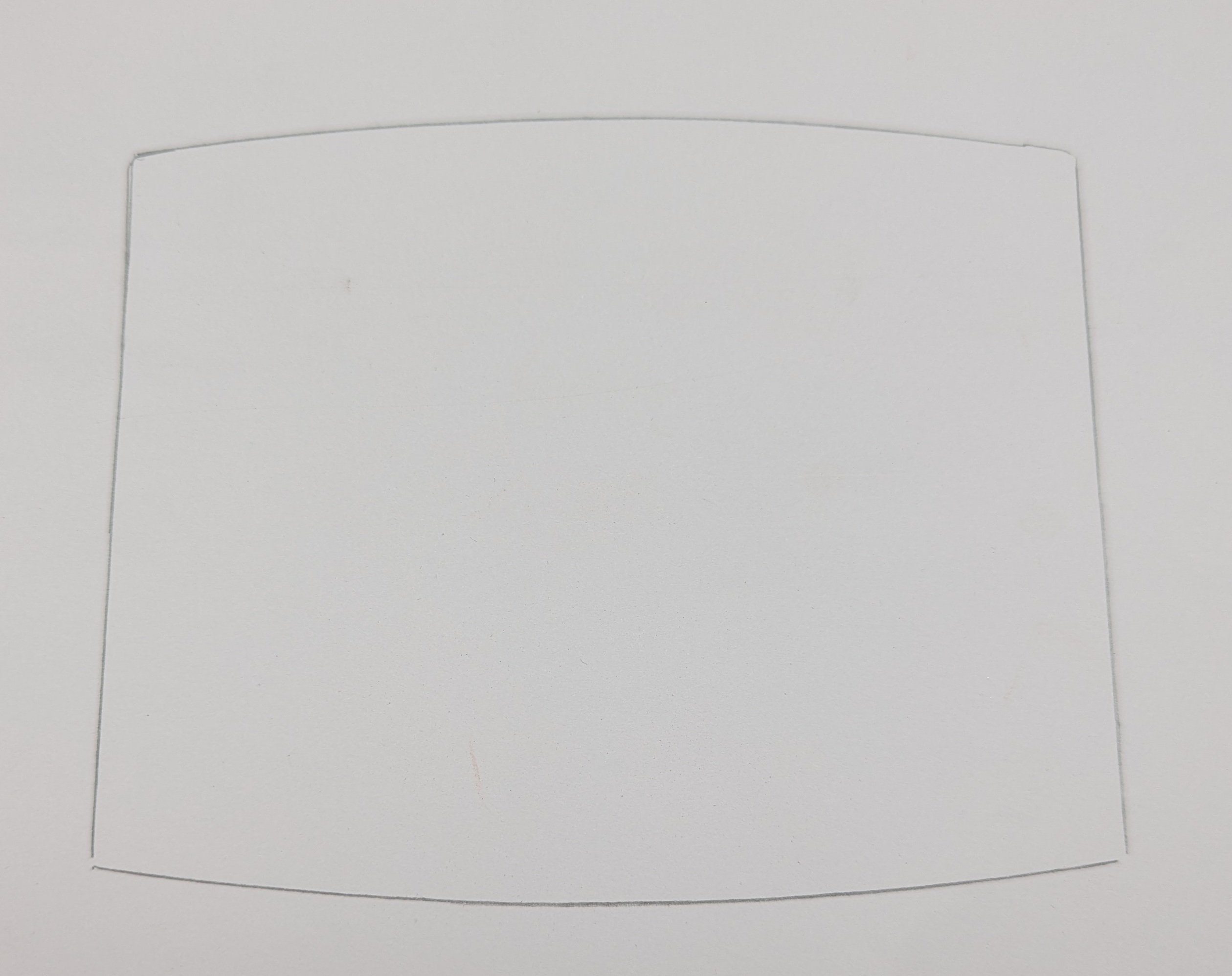
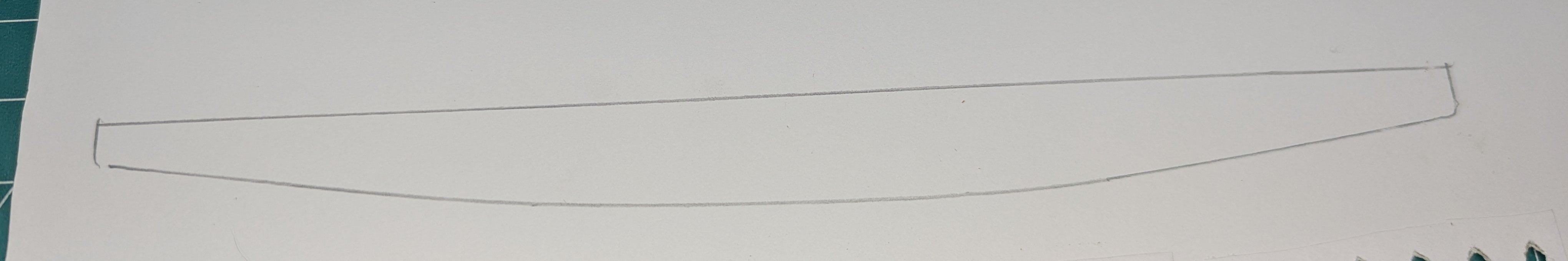
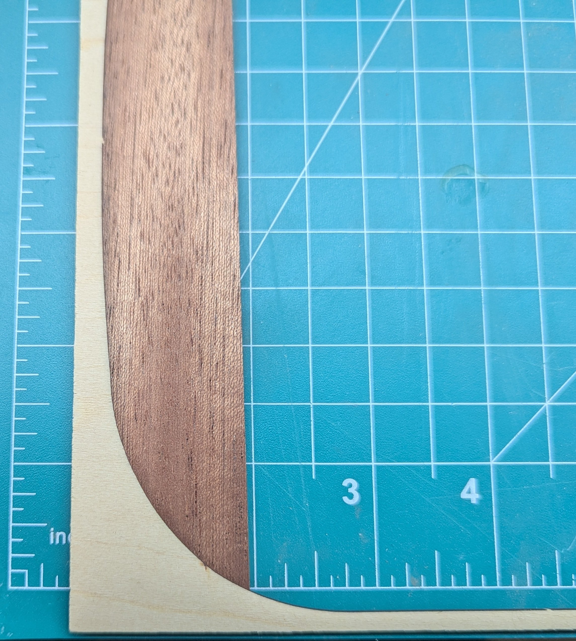
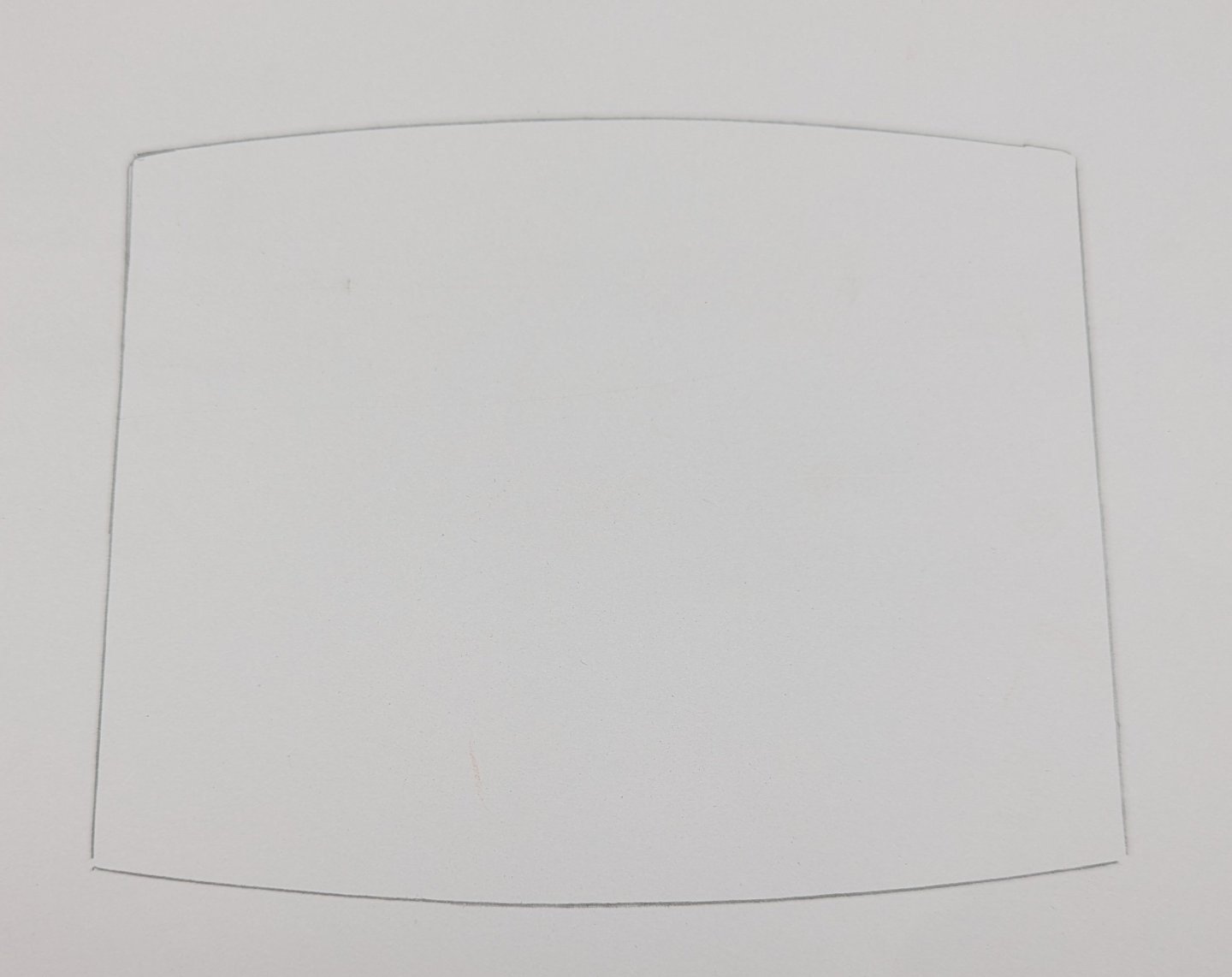
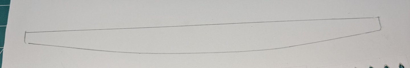
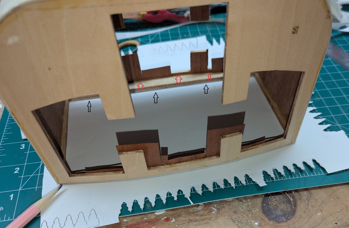
After filling in four corners then proceed to fill in the walls between the walls. Not a big deal as these are flat pieces and go in pretty easy. A more difficult area is the very thin border around the top of the carriage. These are marked by red arrows. I did not do this, but I would recommend when forming these very thin pieces, to cut them very close (a little larger) to the actual size. Than after the glue dries, it will only take sandpaper to smooth them out. In my case the pieces are way to large and I needed to use a cutter to cut away the excess. As mentioned before, these pieces are so thin, cutting them is a challenge. They tend to split just looking at them. Best to only sand them if possible. Next came the curved piece at the top of the carriage (marked with black arrows). Instructions do not mention this, but use the carriage itself as a template to create the curve. As shown below, use some card stock and trace the outside curve of the carriage. From there you will have an outline of the curve Cut that out and you have your pattern. it will be a little long, but better long than short. Just trim the ends to fit inside the carriage From you pattern it is easy to create the correct curve out of the sapelly. Insert it into the curved section of the carriage and you have a perfect fit. Excess will be trimmed later. Again, you just can not have enough clamps 🙂


-
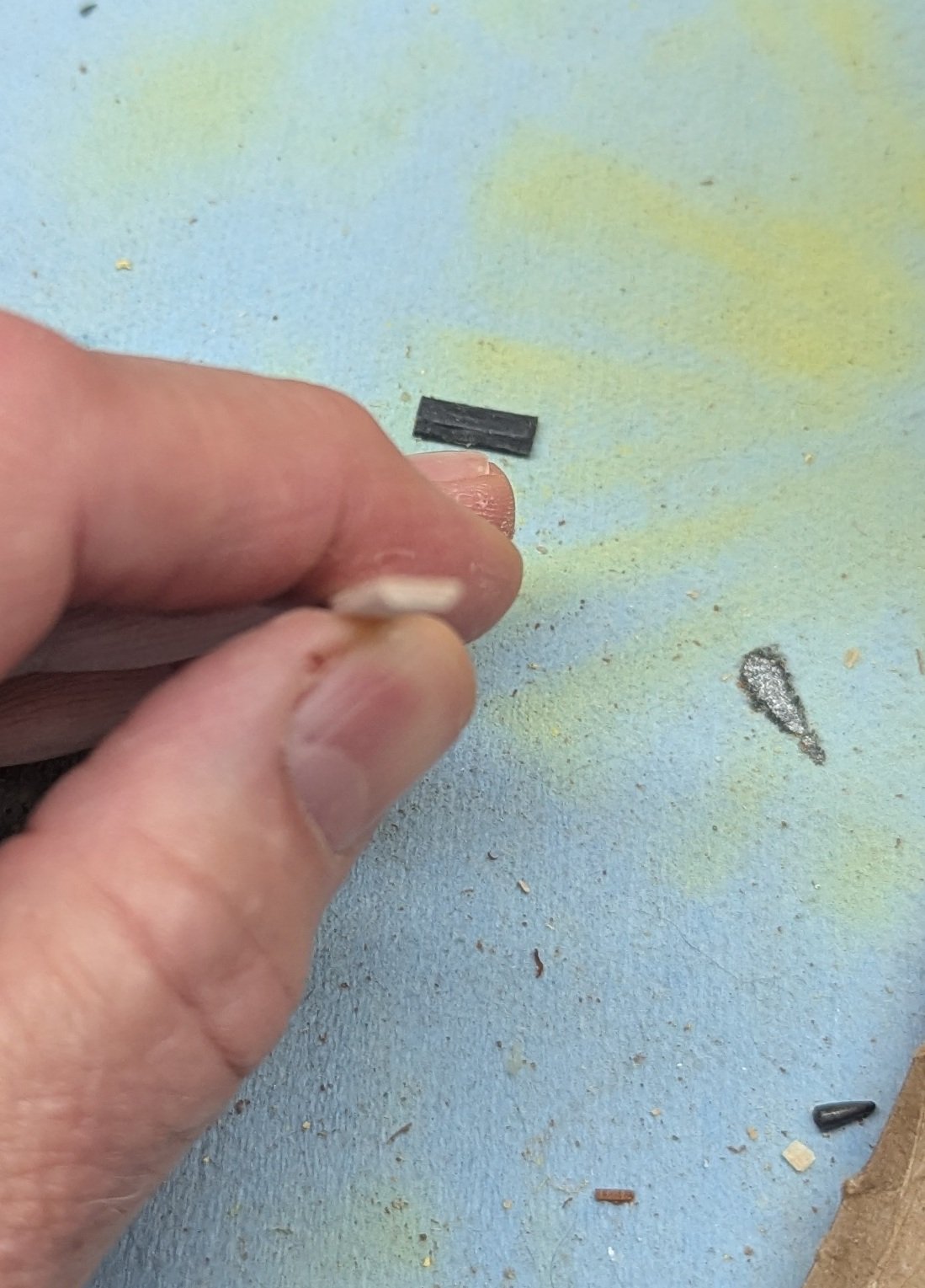
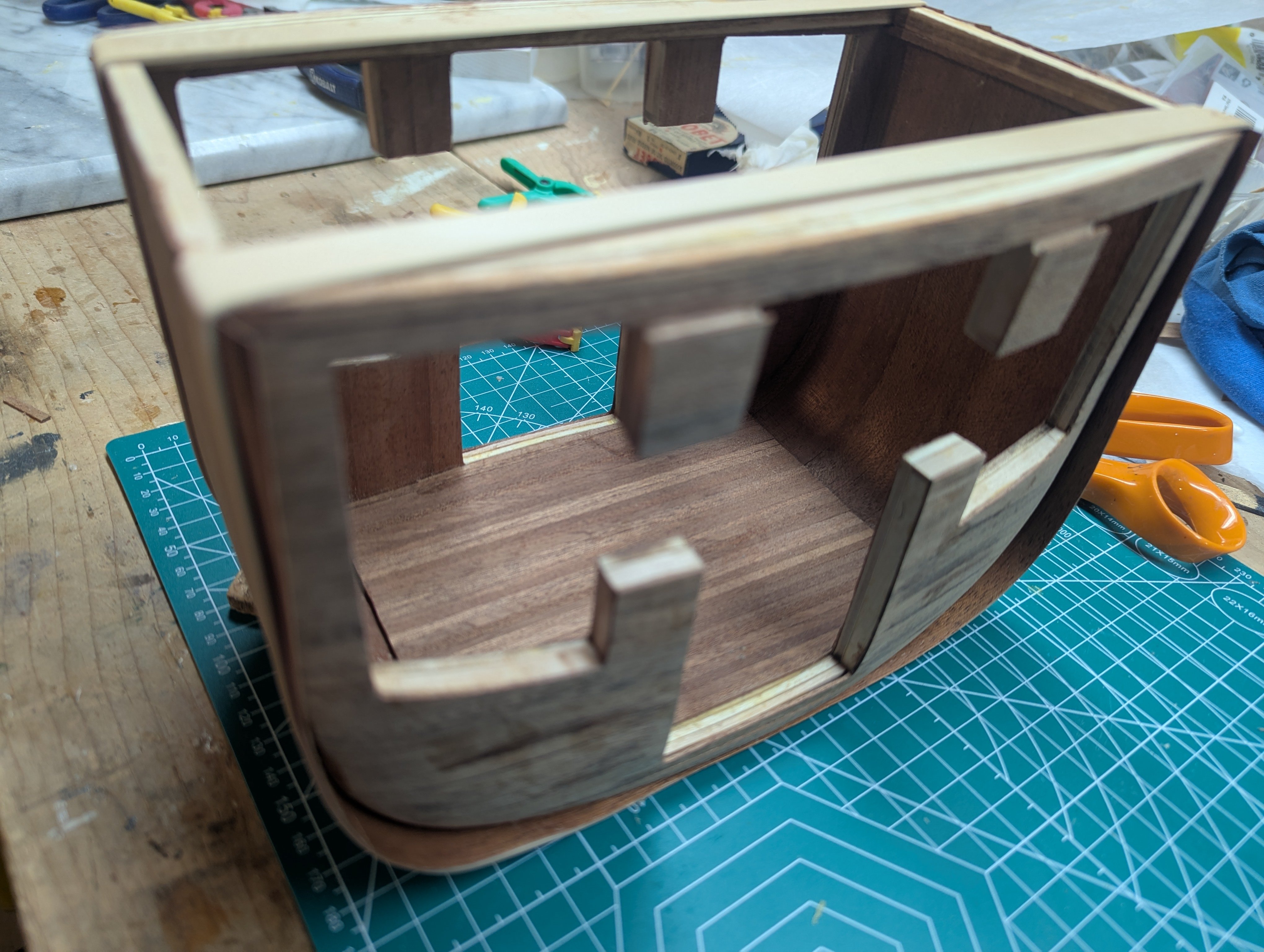
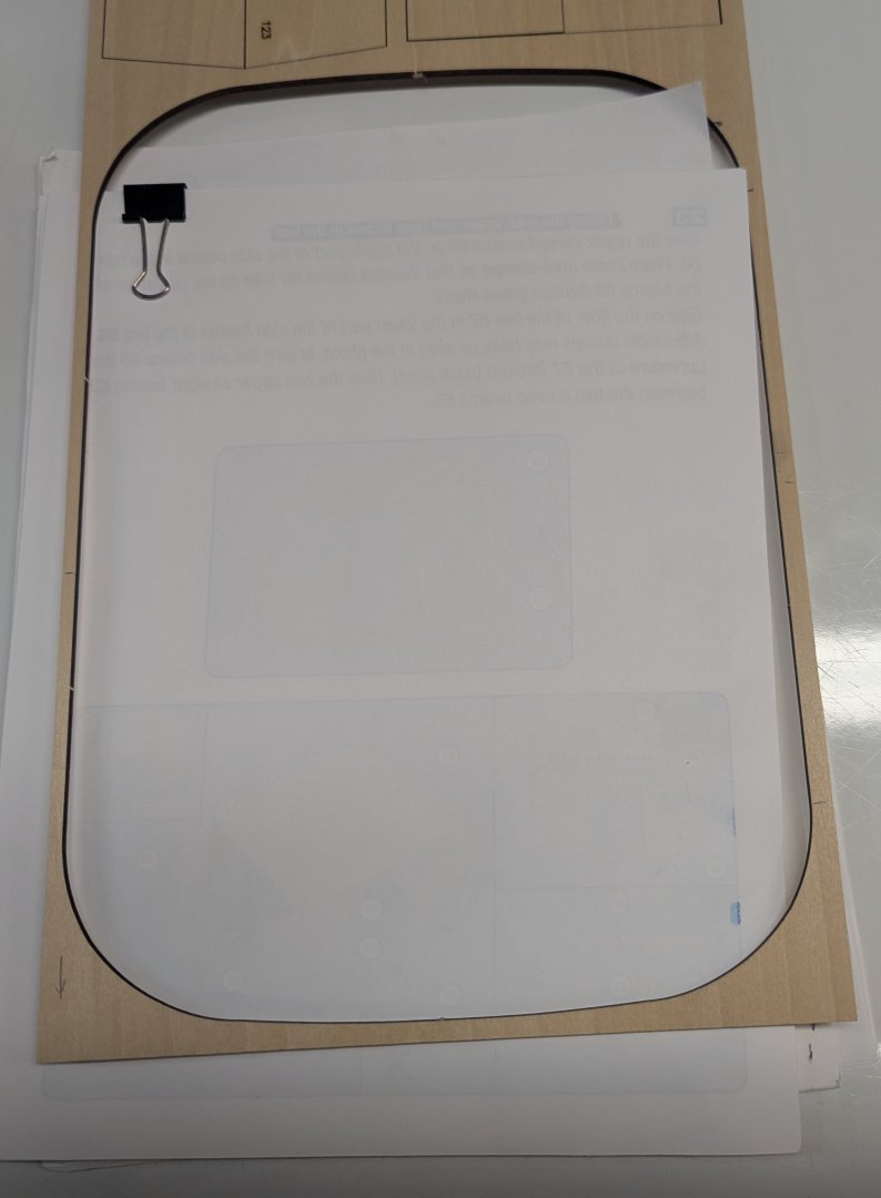
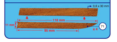
Once both front/back sides are covered, you fill in both left/right sides. Instructions call for a very inaccurate way to measure for the curved sides (Part 71). At my skill level I would have really hard time making that curve match the actual curved corner in the carriage. I pondered it for a long figuring there was no way I was going to be able to make that curve match the carriage. Finally realized, and I am not sure why the instructions did not talk about this, but you already have a template that will match the curve exactly. That being the outline of the sheet wood that contained both sides of the carriage. Insert a sheet of the sapelly into the frame and you have the exact curve. Use a pencil to mark the curve and cut it out with a sharp scissors. Again, this wood is so thin a scissors works far better than even a sharp exacto knife. I am sorry I did not get a picture of the resulting piece, but it really is the exact shape of the curve. Below you see the shaped piece inserted into the corner of the carriage. Using the supplied template is really the only way to do this.. After all four corners were in place, just started going around the inside of the carriage inserting in the straight pieces. Note each piece is a little long and will be trimmed later. I think (hope) it will be easier to trim around the windows and doors later on then try to trim the pieces to make at exact fit prior to gluing them in


- 20 replies
-
- 12
-
-
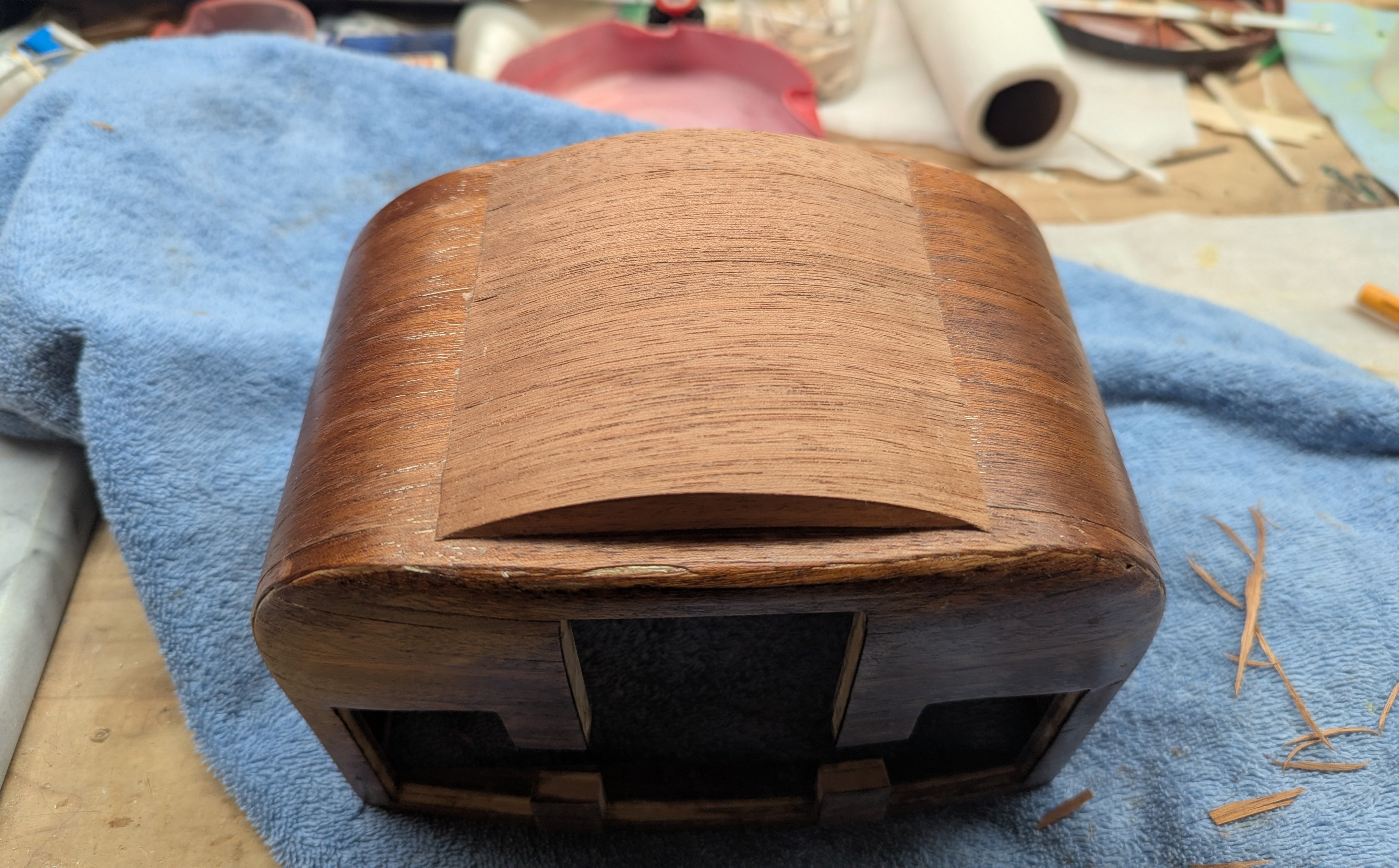
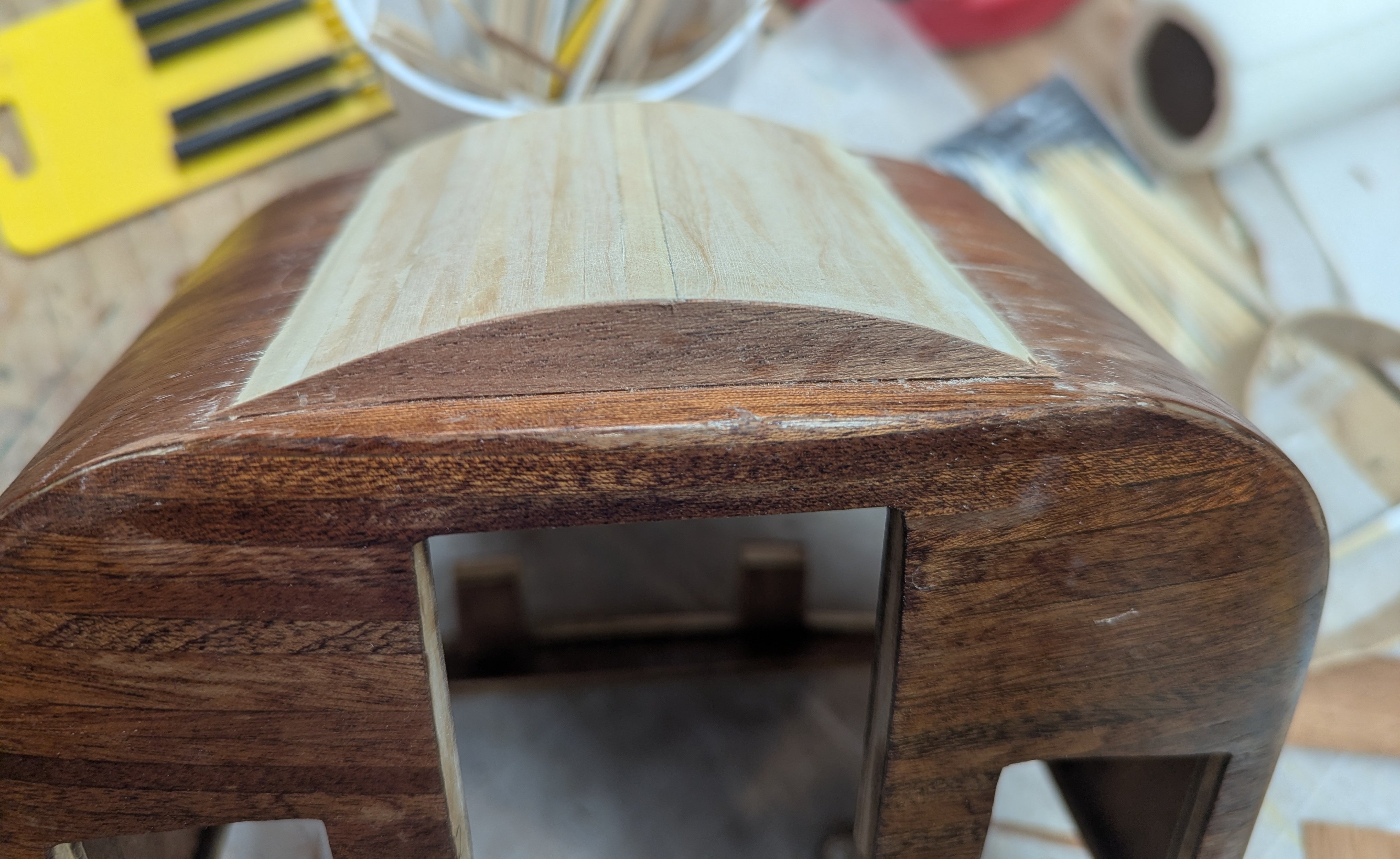
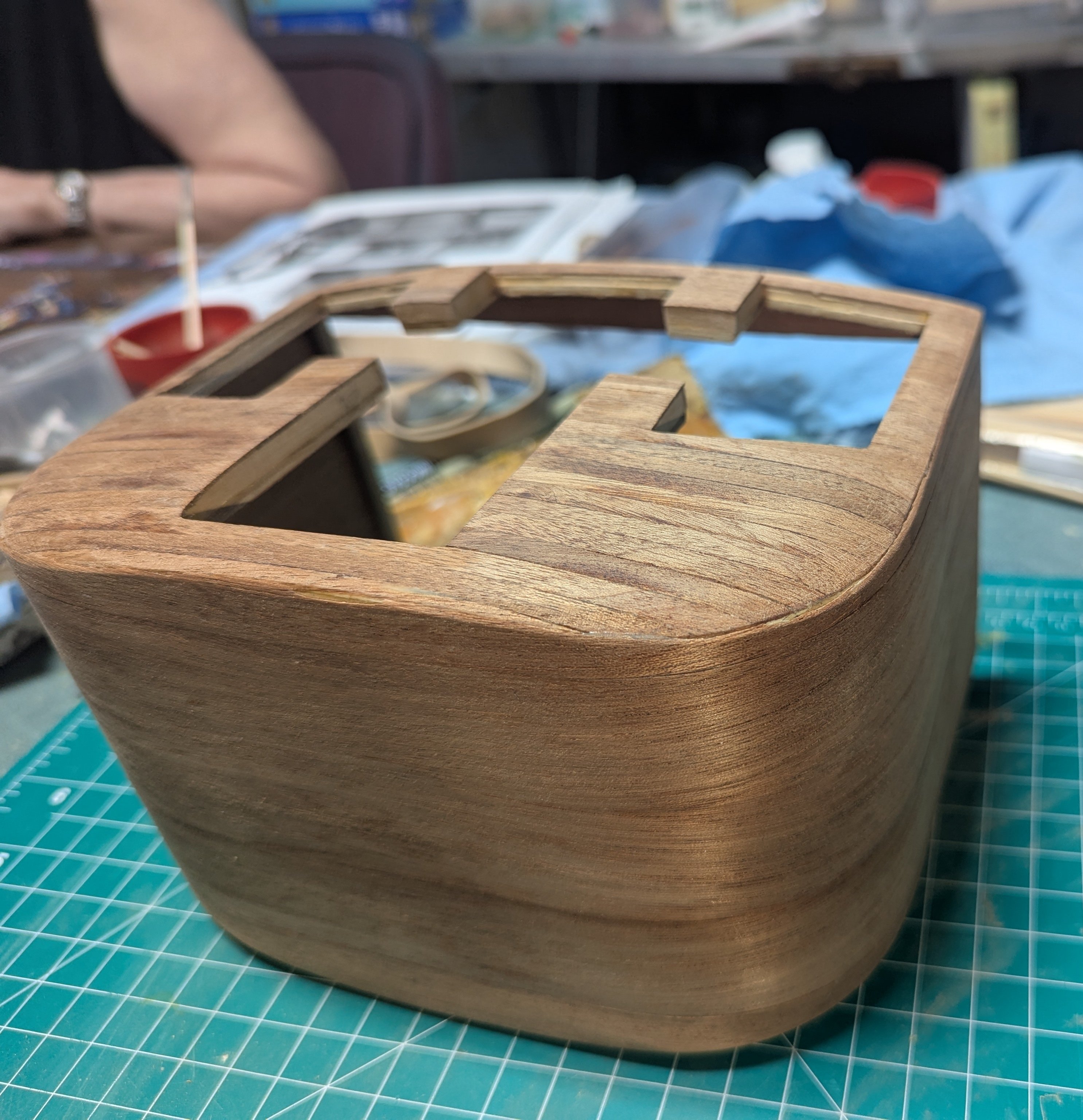
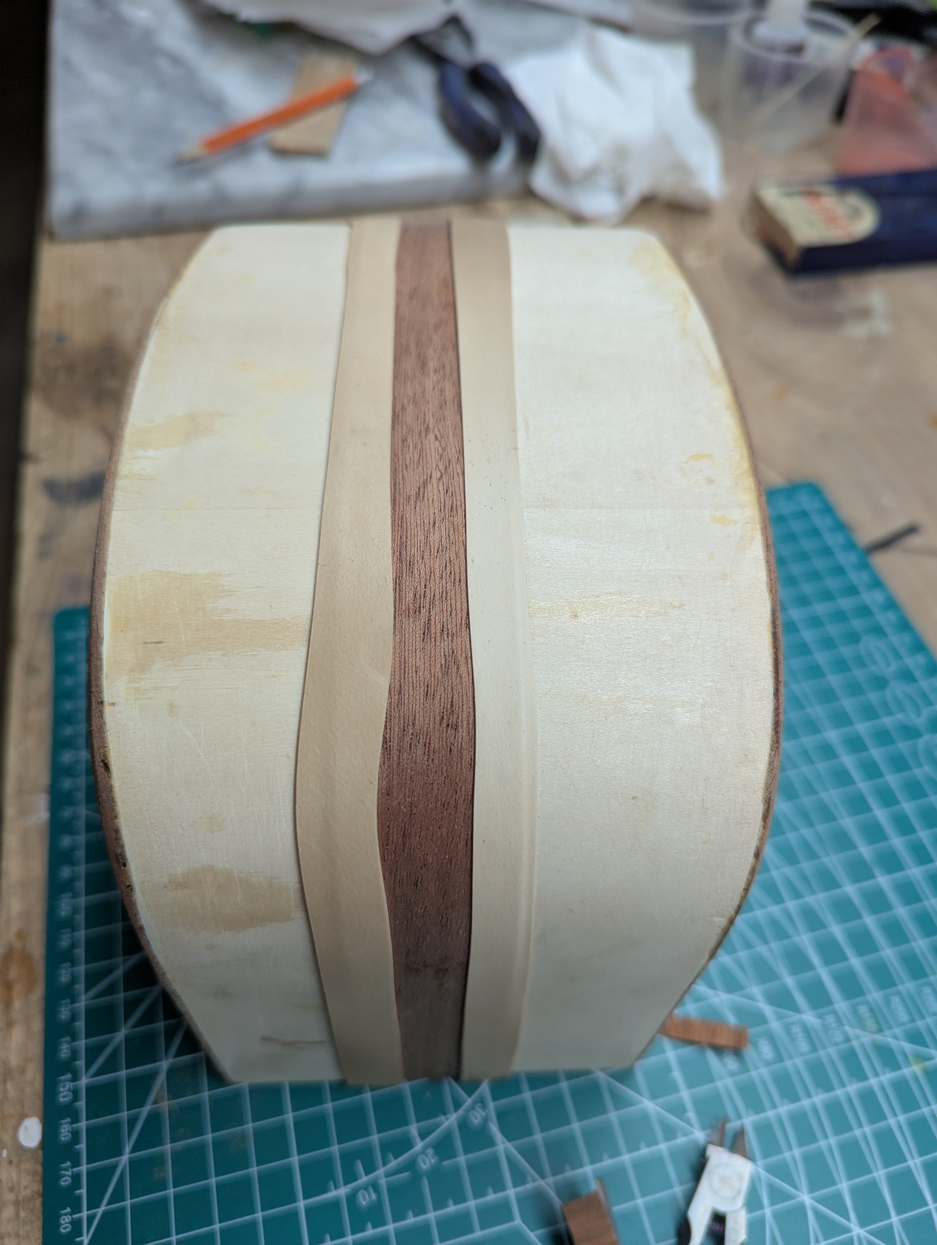
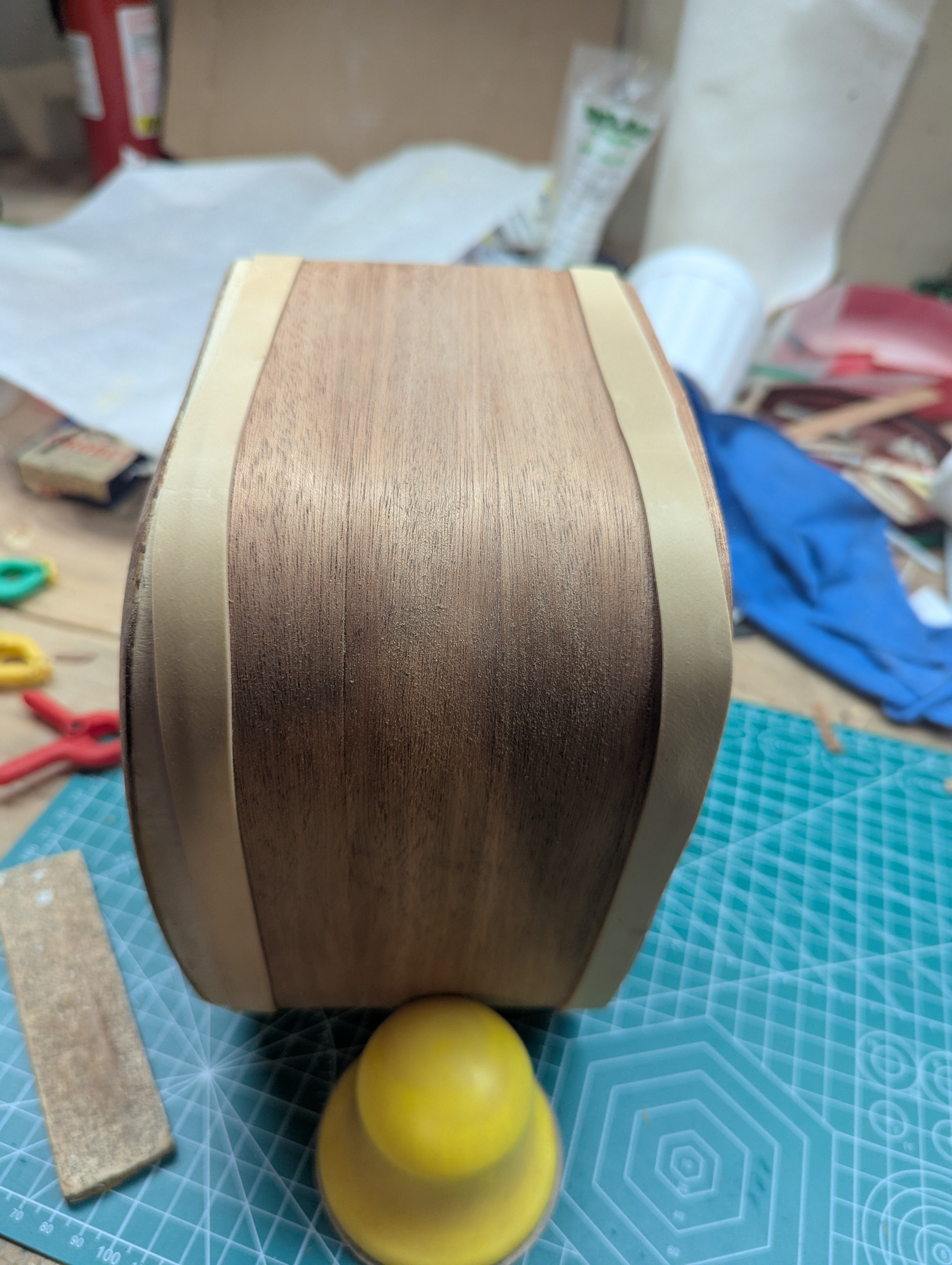
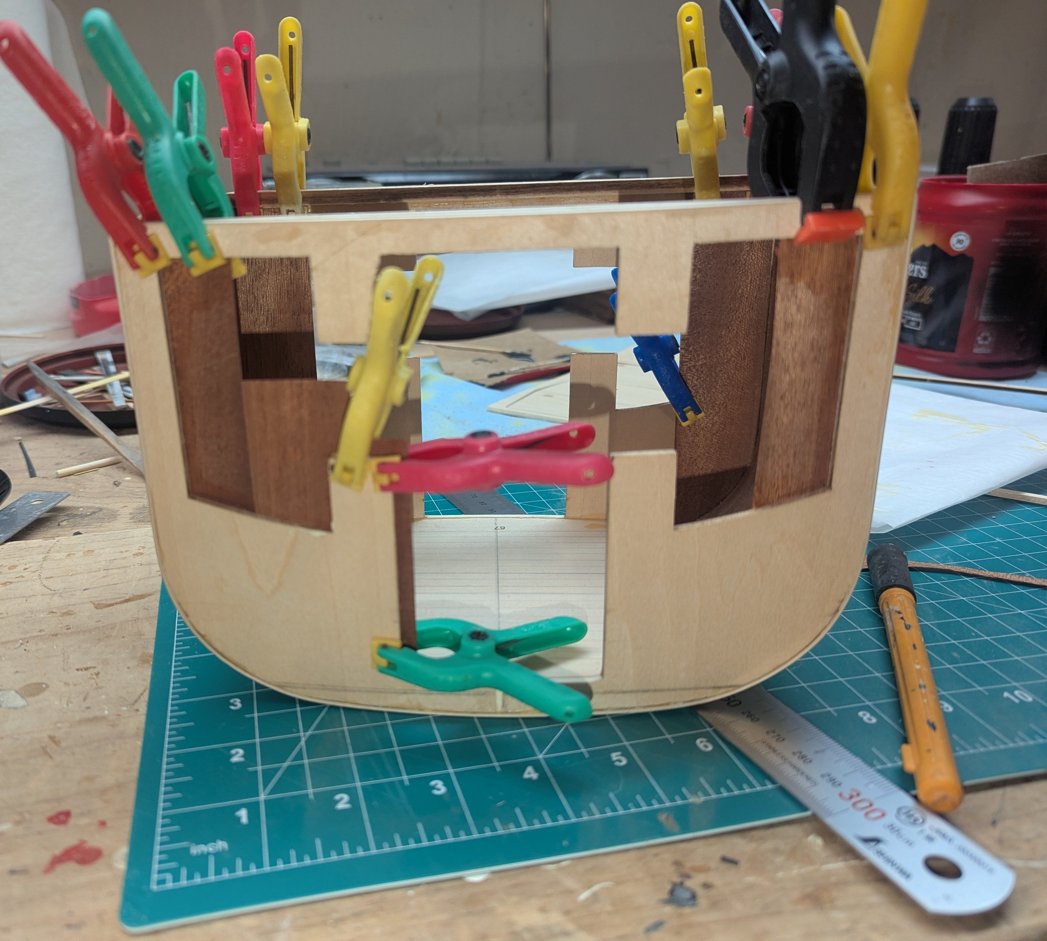
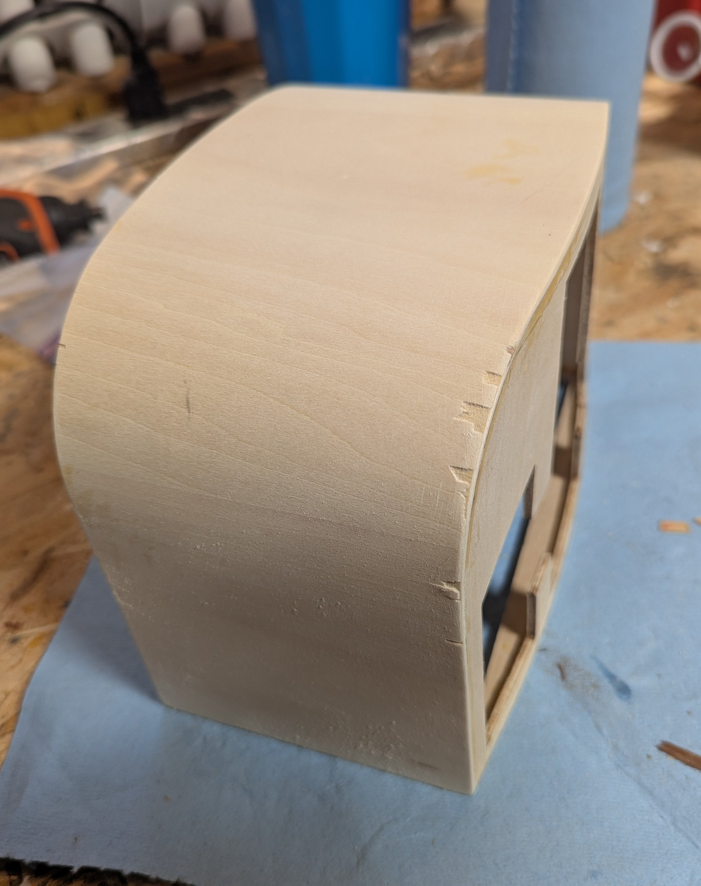
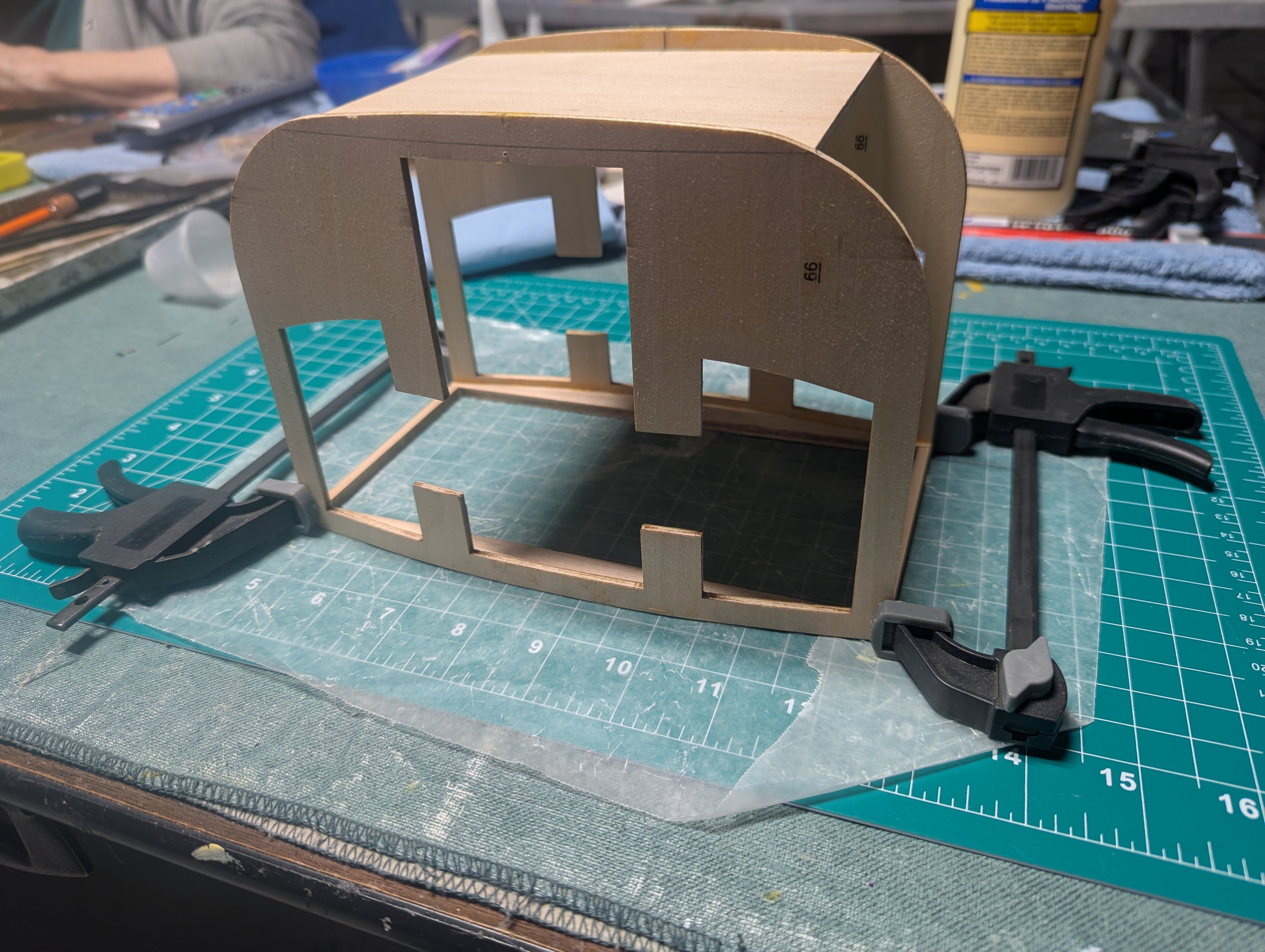
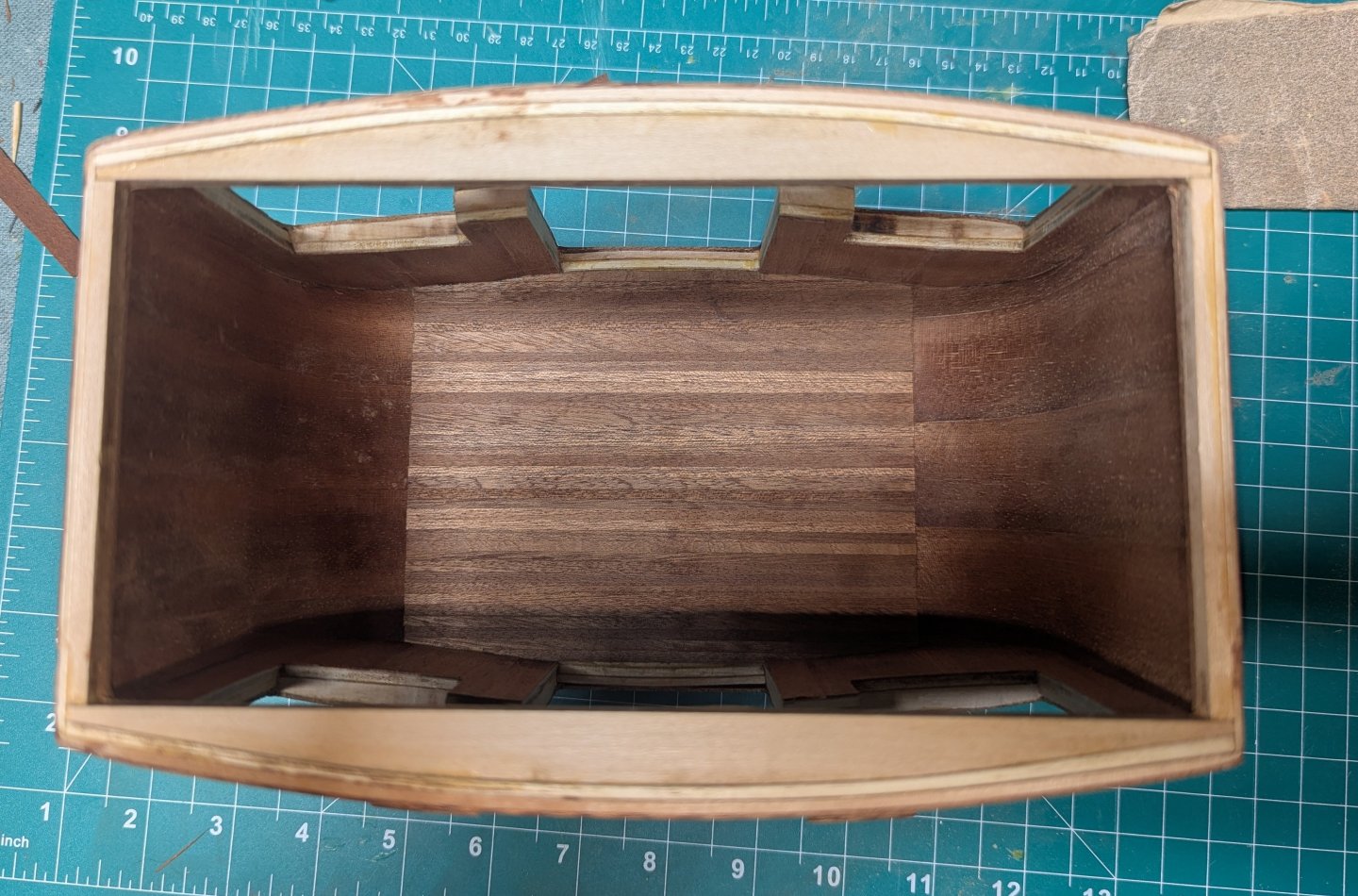
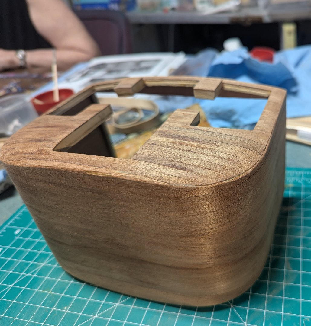
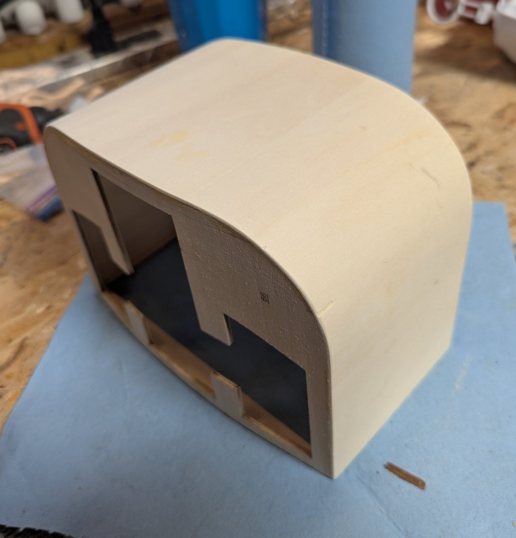
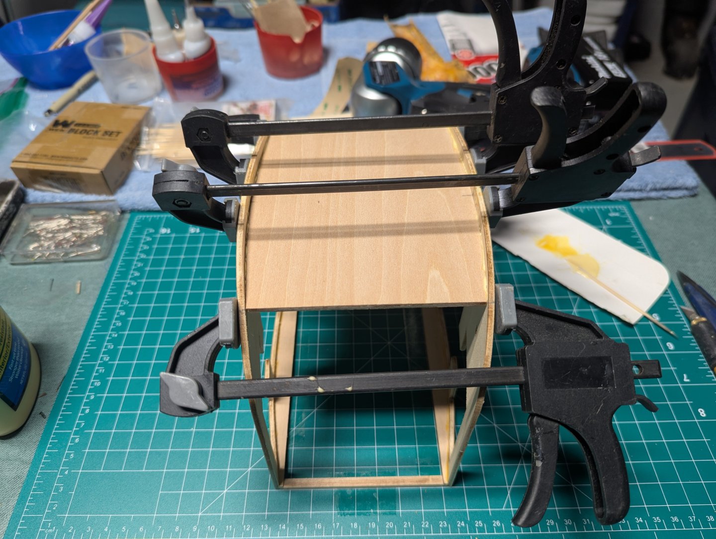
Next come bending the cover over the carriage structure. Instructions calls to start at one end and slowly with CA glue bend the wood over the cover. To me that seemed kind of hard and i am not a big fan of CA glue when wood glue would work. To me the easiest way to ben the cover over the structure was to slightly dampen the cover - both sides. Find the middle of the sheet and clamp the carriage to it. I then used a heat gun to soften the wood (not sure that was necessary) and slowly bent each side up at the same time. Again, make sure the carriage is securely clamped to the center of the wood sheet. At that point l the sheet is up over both sides, clamp it well and let it dry overnight. Next day remove the clamps. The cover sheet will flop down some, but can easily be bent back. Add some wood glue to all glue spots and clamp well. Again wait over night for the glue to really set up. In addition to clamps, some rubber bands were added at the curve to make sure it was also well glued. Next day when clamps are removed all is good Used an exacto knife and sand paper to remove the excess wood. I forget exactly what happened here with the gouges, but it had nothing to do with bending the wood. I seem to remember "trying to be cute" and "Fast" with the wood trimming and these gouges were the result. Not a big deal. A little wood filler and all is good with the world On to lining the inside of the carriage with the really thin .06mm sapelly wood. That is really thin... it splits and cracks just looking at it. I found one was that worked for me in cutting the sapelly was to use a sharp scissors. It is especially hard on both sides of the carriage as the sides are curved. So you have to shape the wood and it can be a challange do to the wood being so thin. Once side complete Second side complete. I am not too worried about the middle piece on the left being a little short. In the end, when the floor is laid and seats added, that little gap will not be seen. However, there really was no excuse for that piece being short.... other than lack of skill on my part 🙂


-
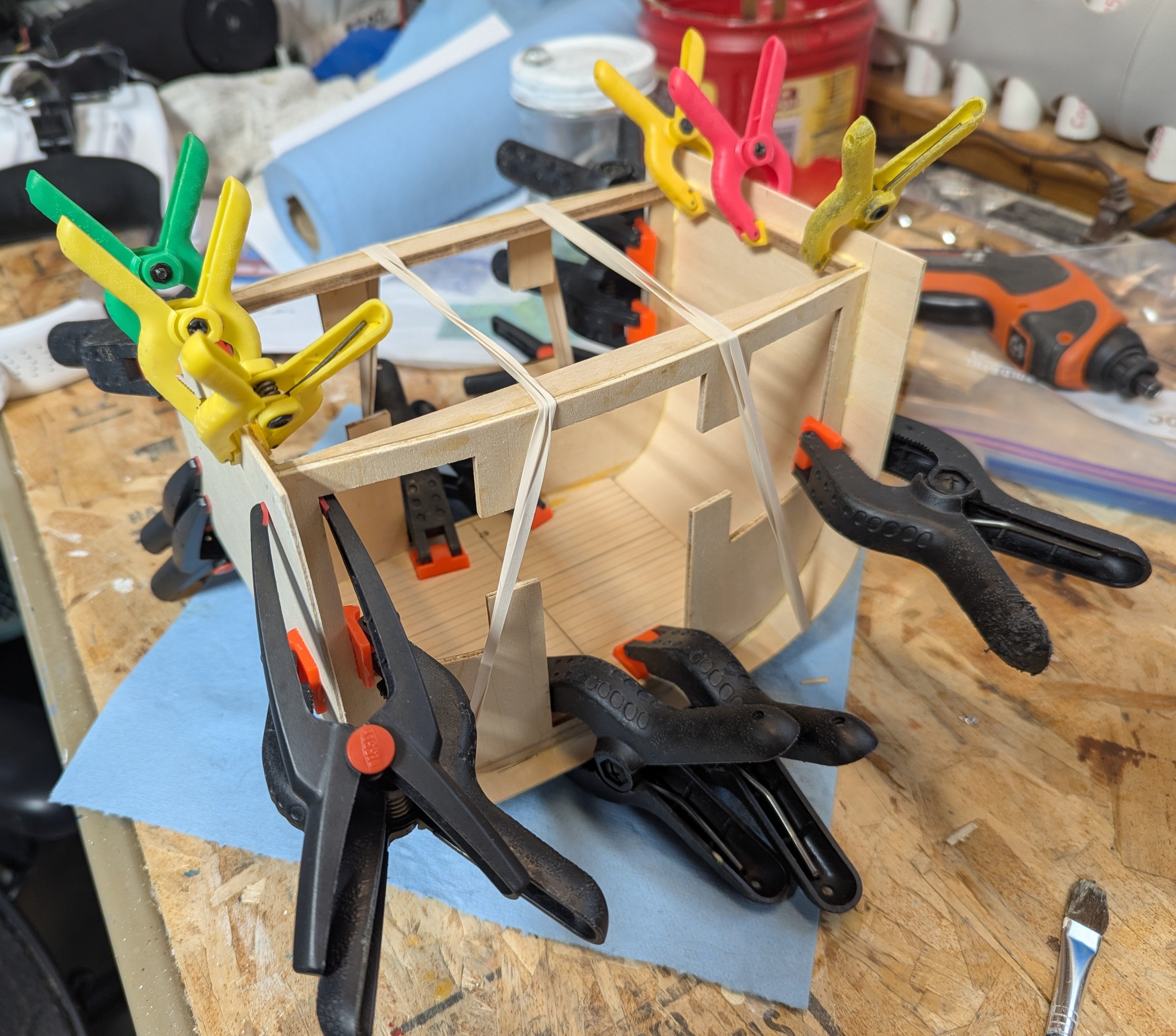
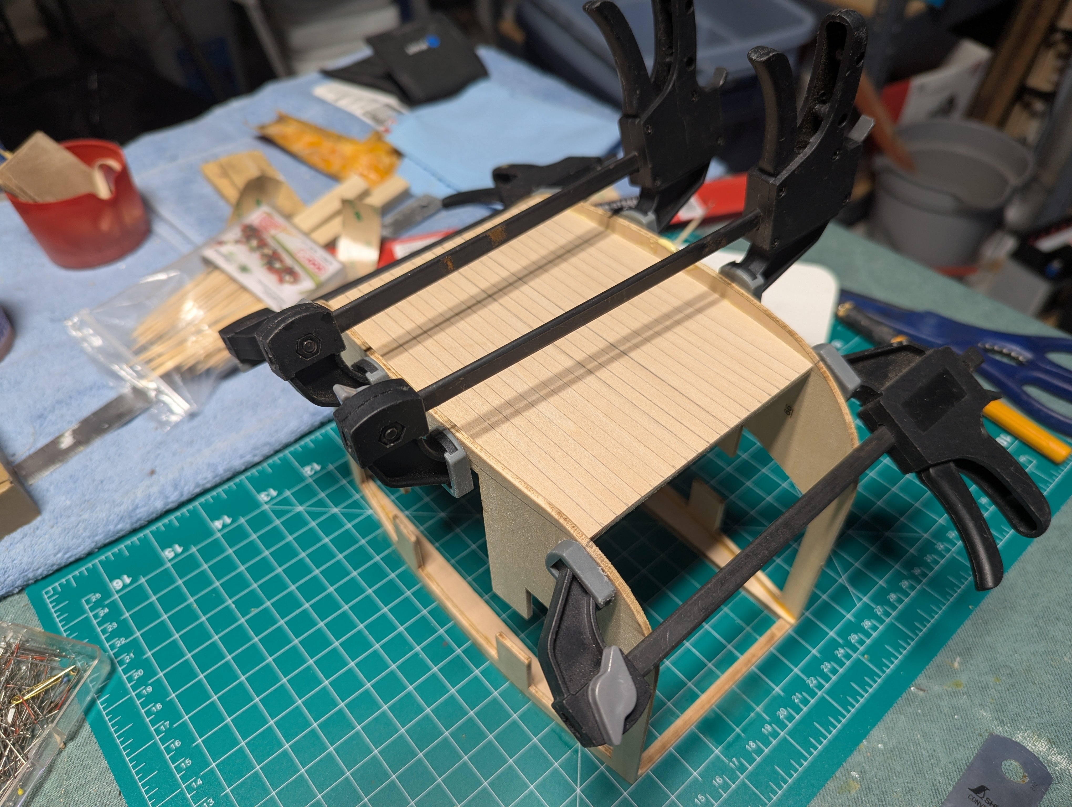
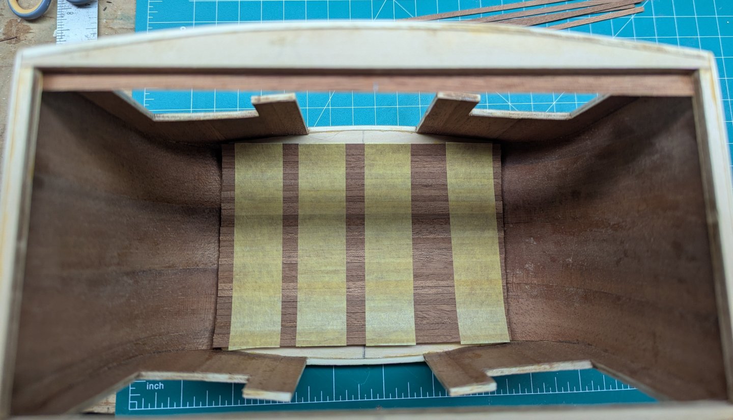
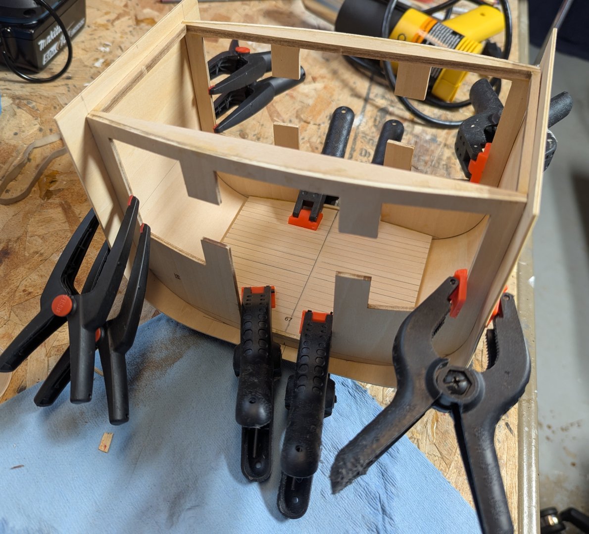
Next step call for gluing the floor between the curved walls. Instructions say to do this like it is not big deal. And for a more experienced modeler maybe it is obvious. I spent way too many hours successfully discovering all the ways not to do it. May issue is the fact that the wall are not yet secure, so gluing on the bottom proved challenging. Anyway secret (for me anyway) was to use double sided tape. Tape holds the sides steady while the top is glued. Here again, ways not to do it. I initially used some 30 lbs double sided tape. As soon as I stuck on the first piece, I knew I was in trouble. Tape was way too strong and I felt I would break the piece trying to get it off the tape. I then used some 6 lbs tape. Again too strong, but that is was I used. After glue dried, with a putty knife I slowly worked off the pieces. If you have some plan double sided tape around, you might try that. I may or may not be strong enough, but it is worth a try. All it has to do is keep the base from moving around while you glue on the floor. A few pictures showing the floor being glued onto the carriage. With the base secure due to the tape, it was pretty straight forward. And finally gluing on the two straight beams


- 20 replies
-
- 10
-
-
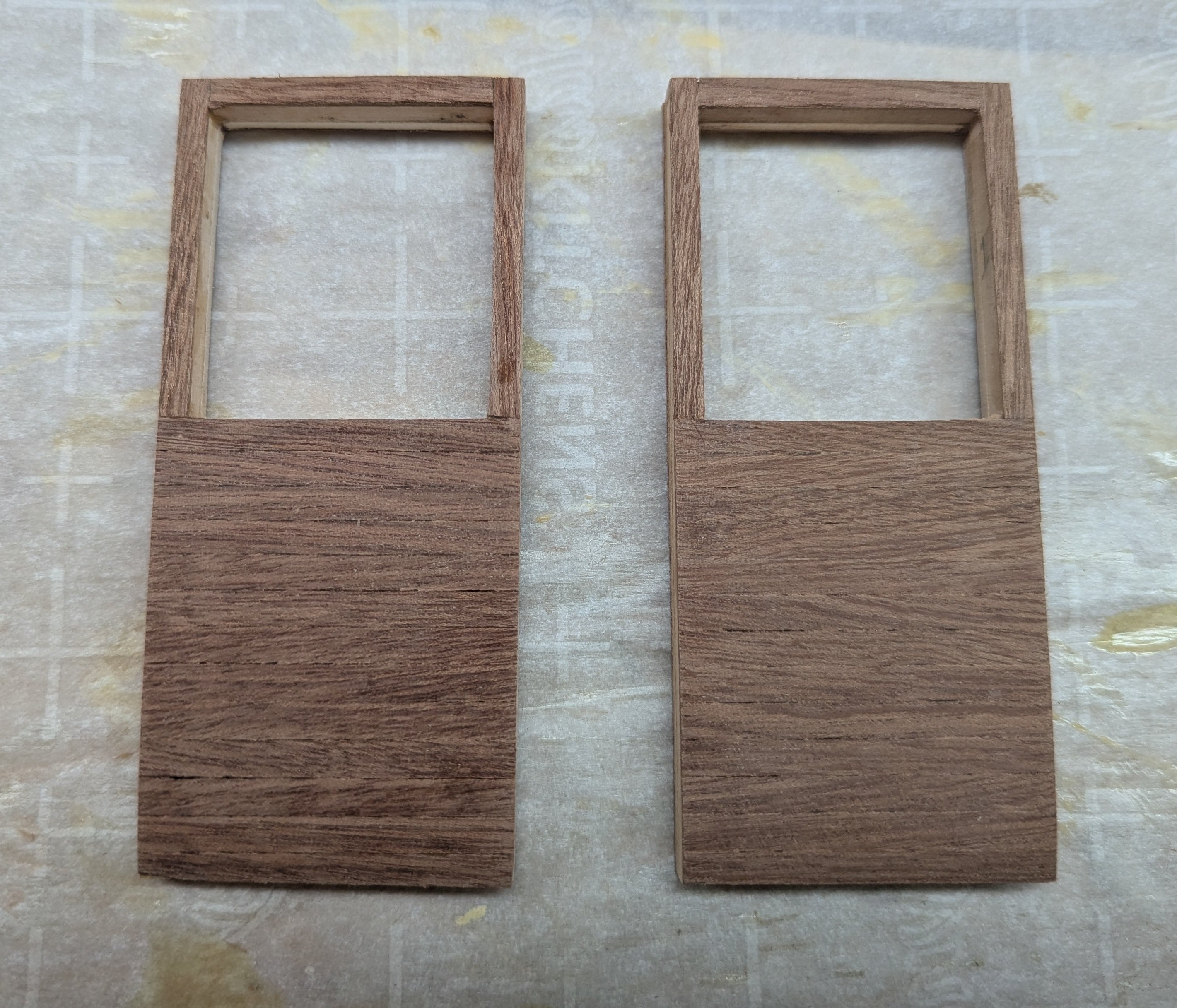
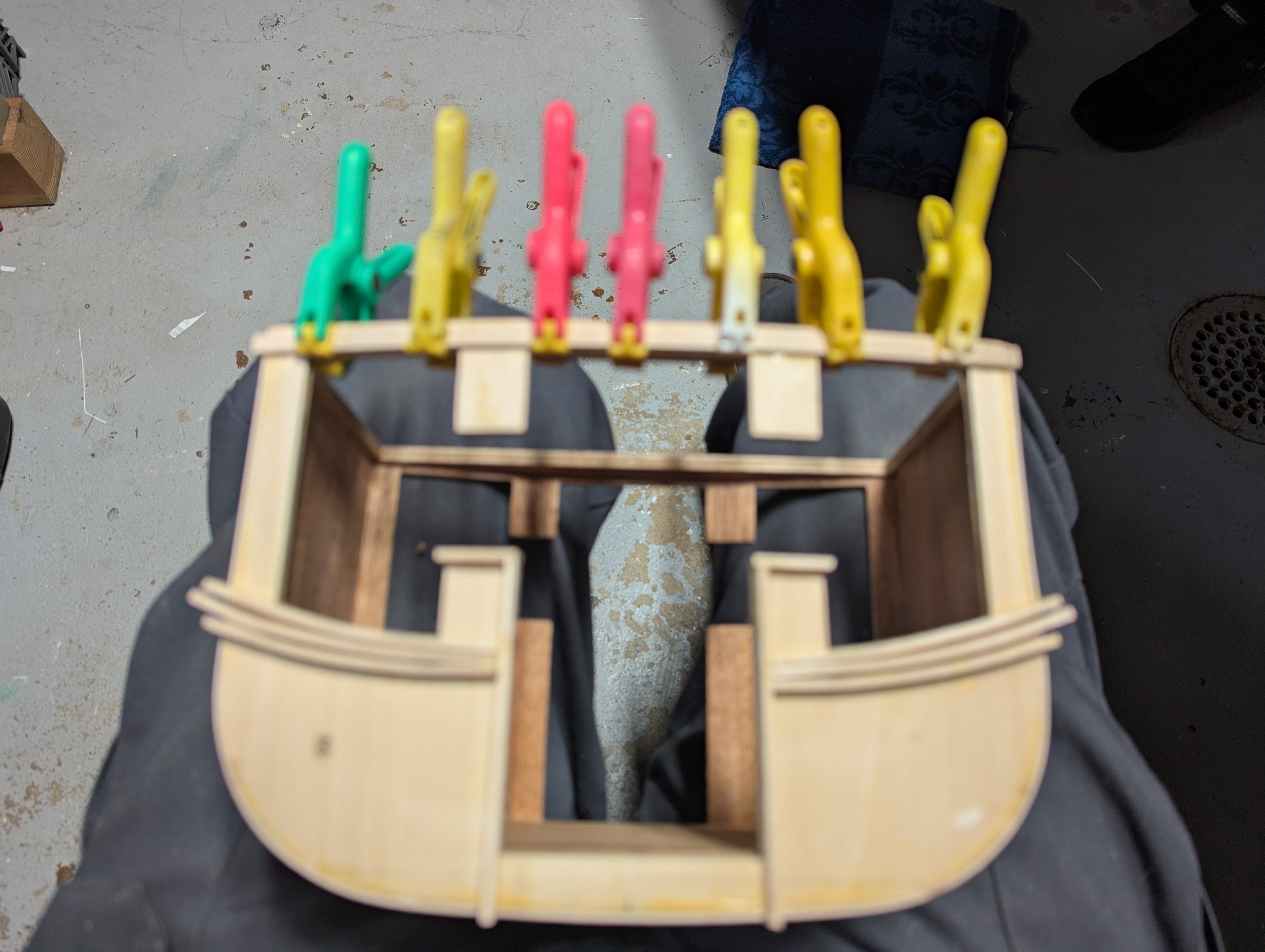
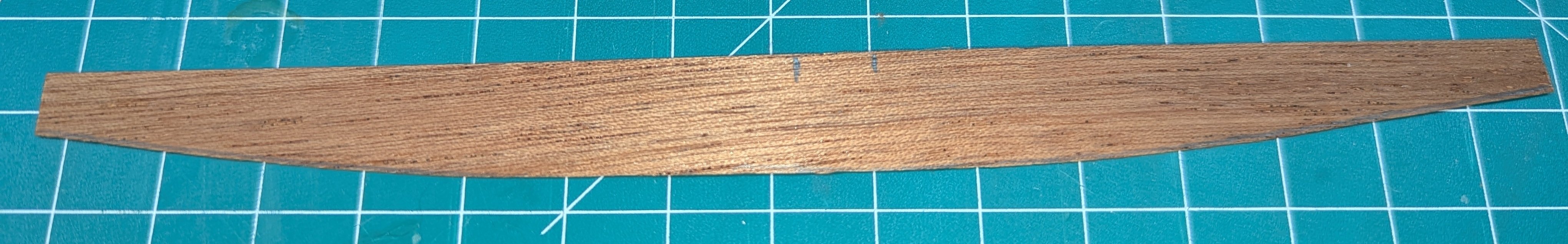
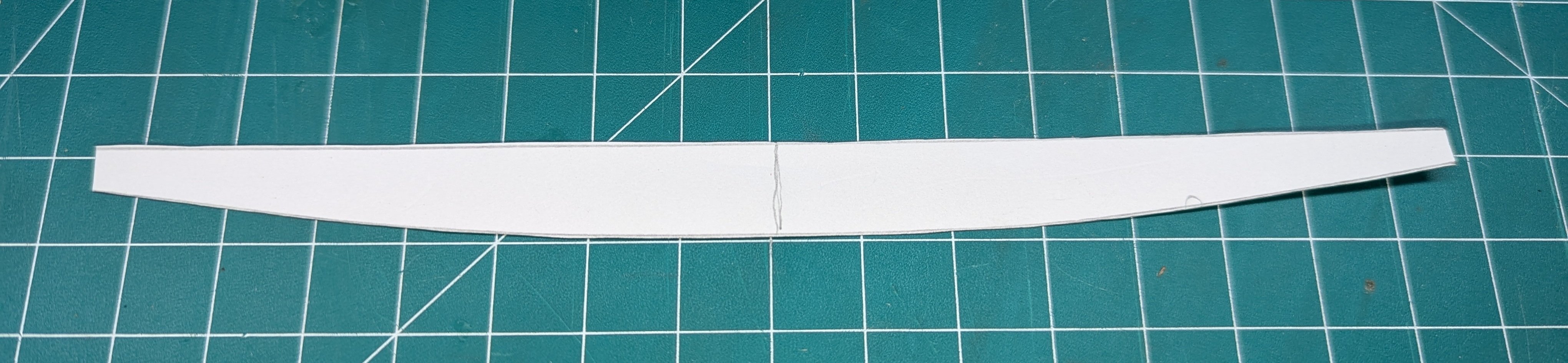
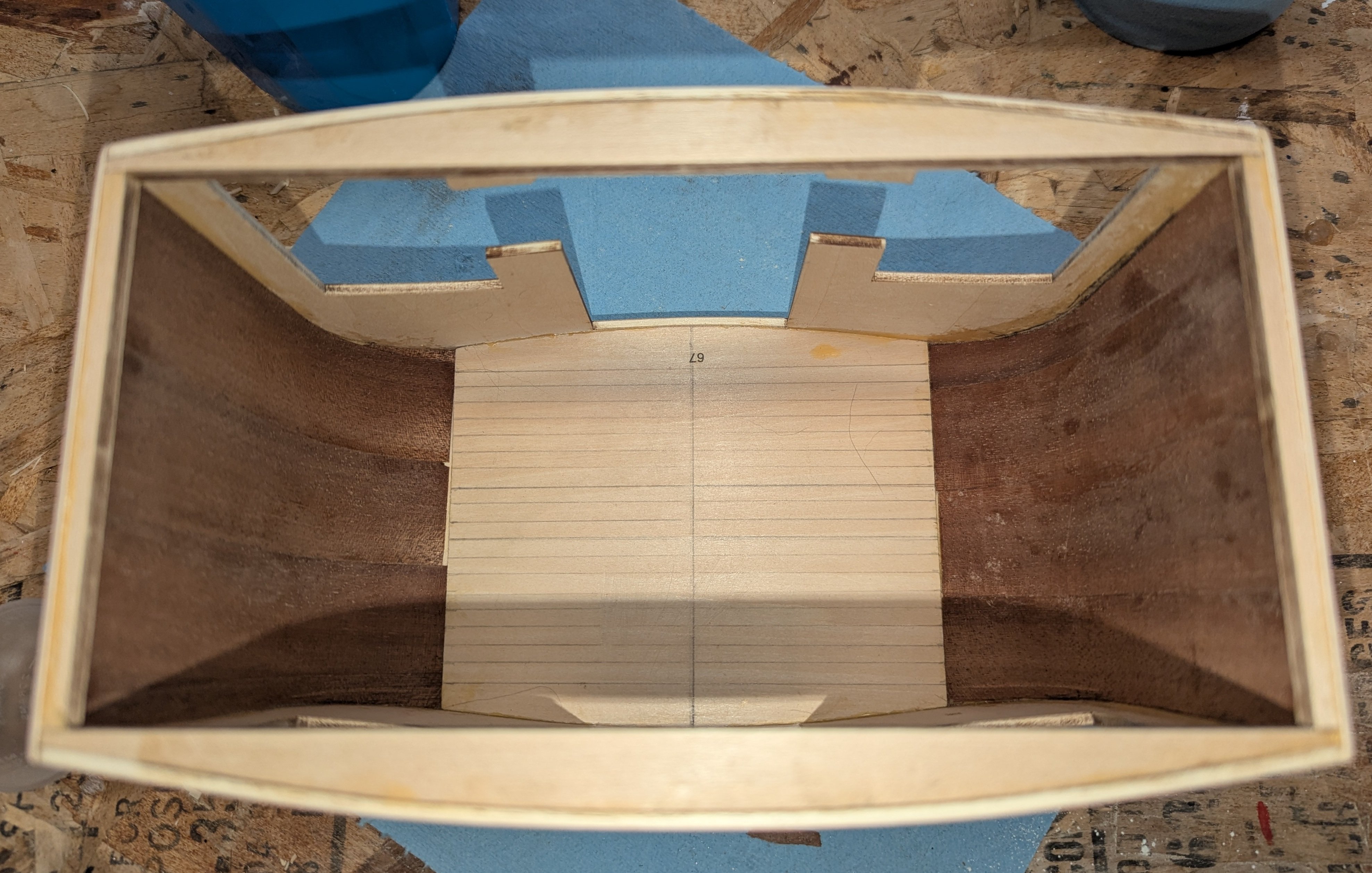
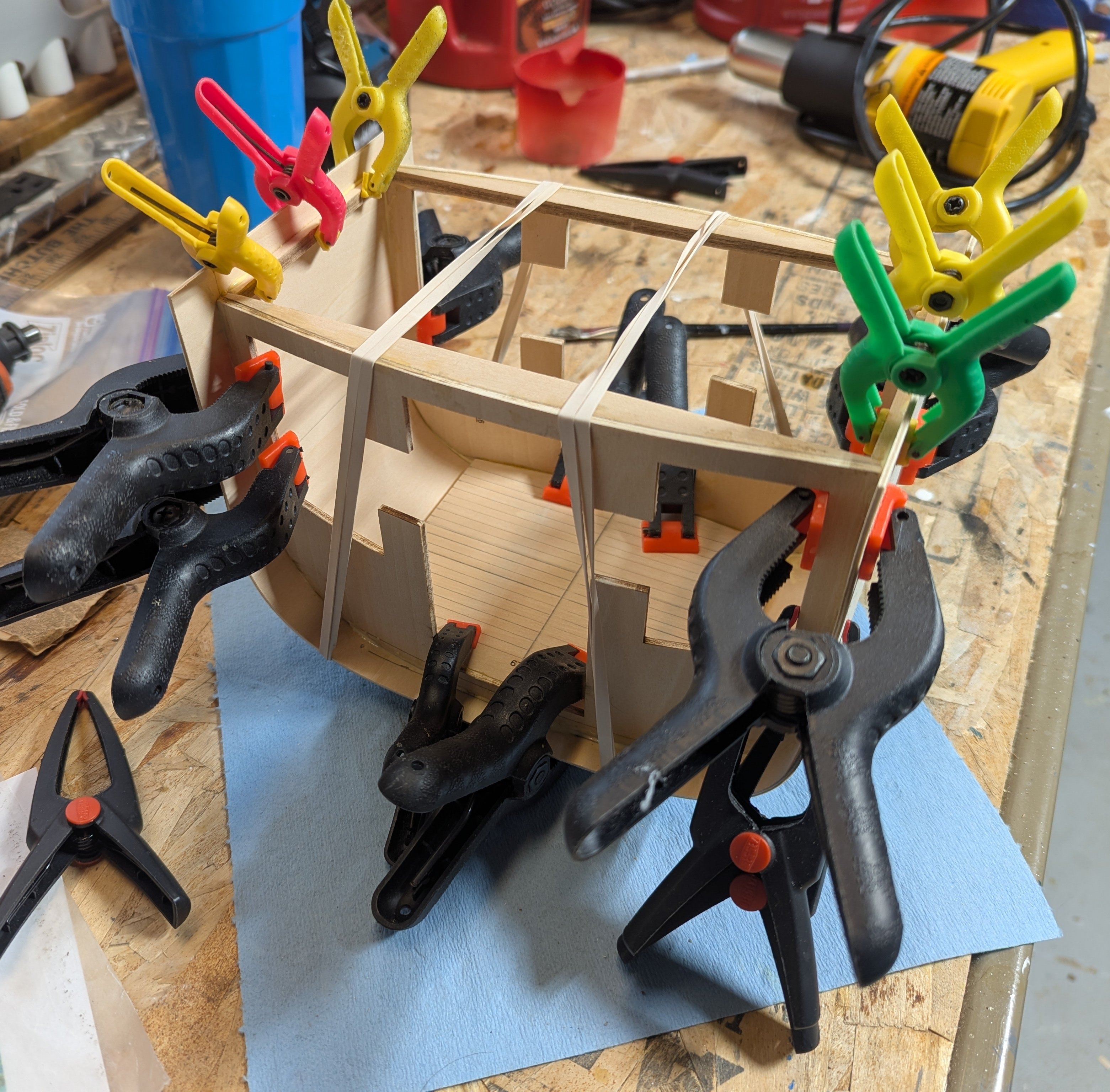
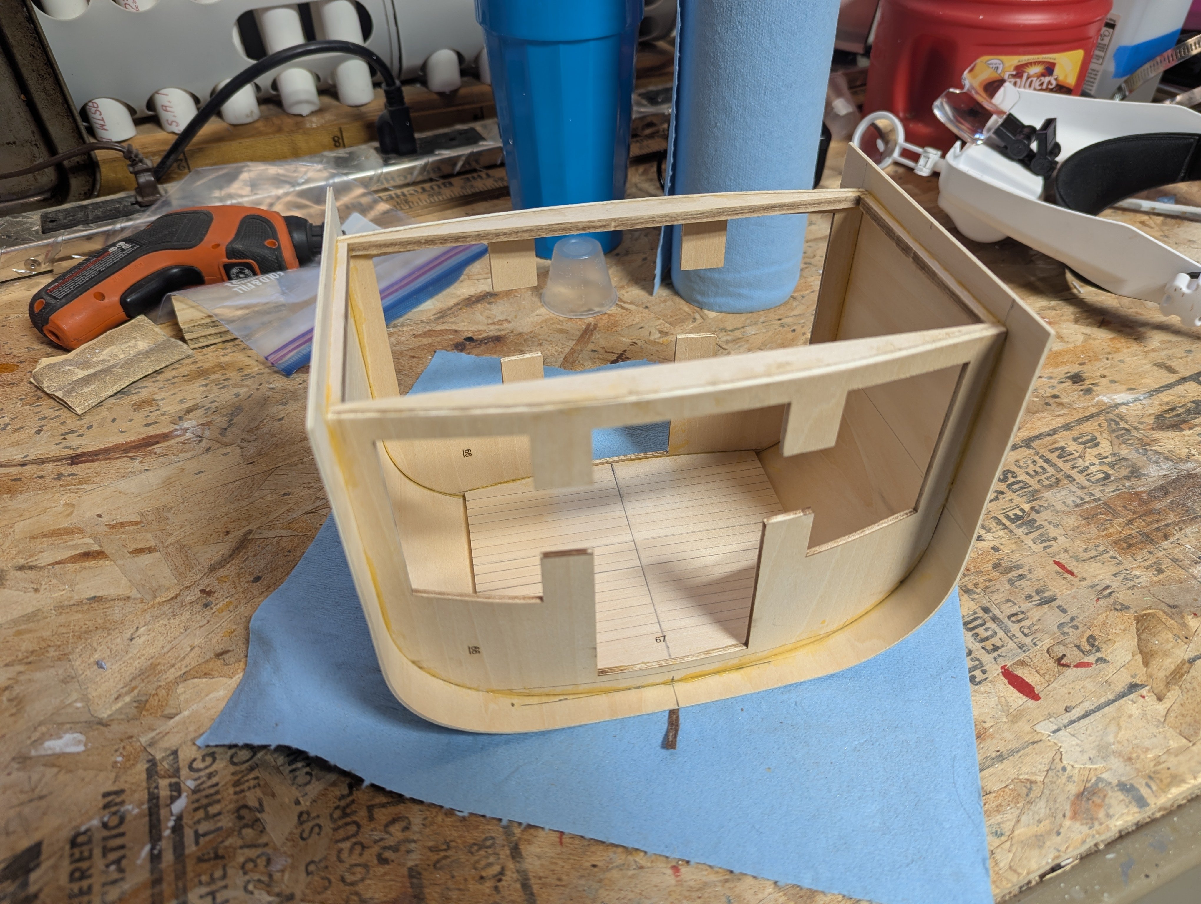
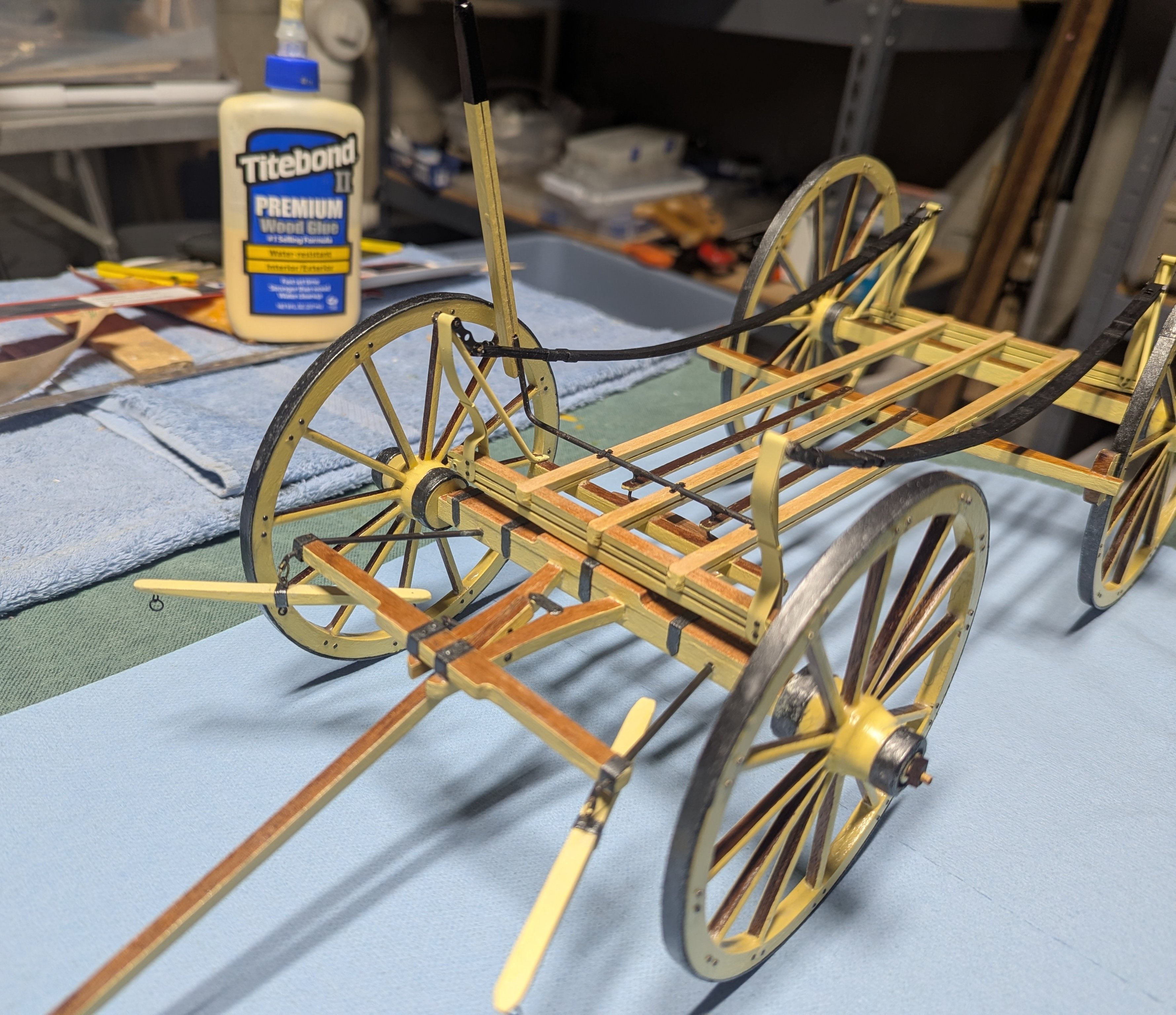
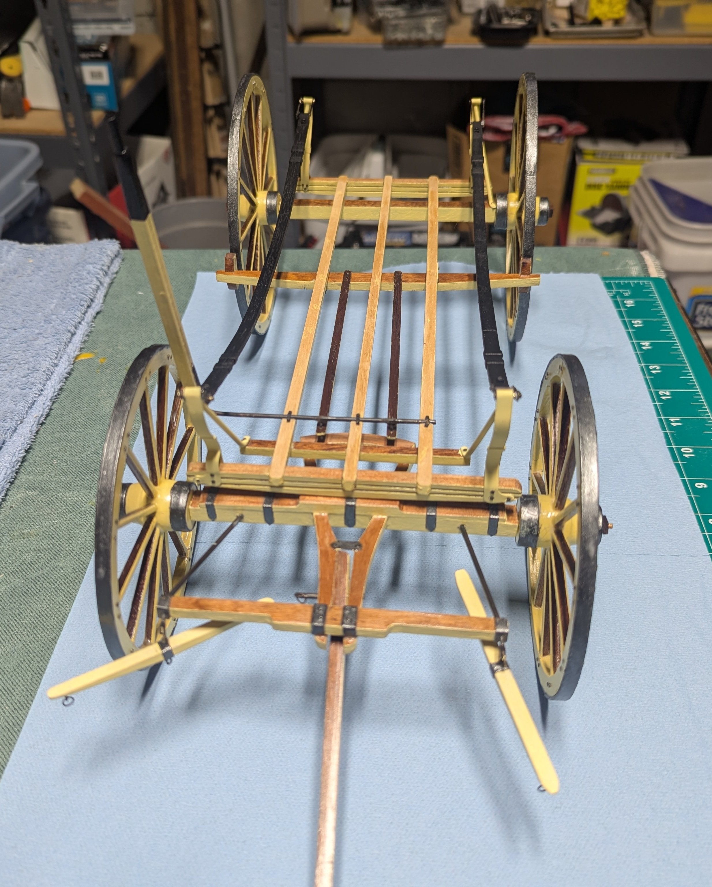
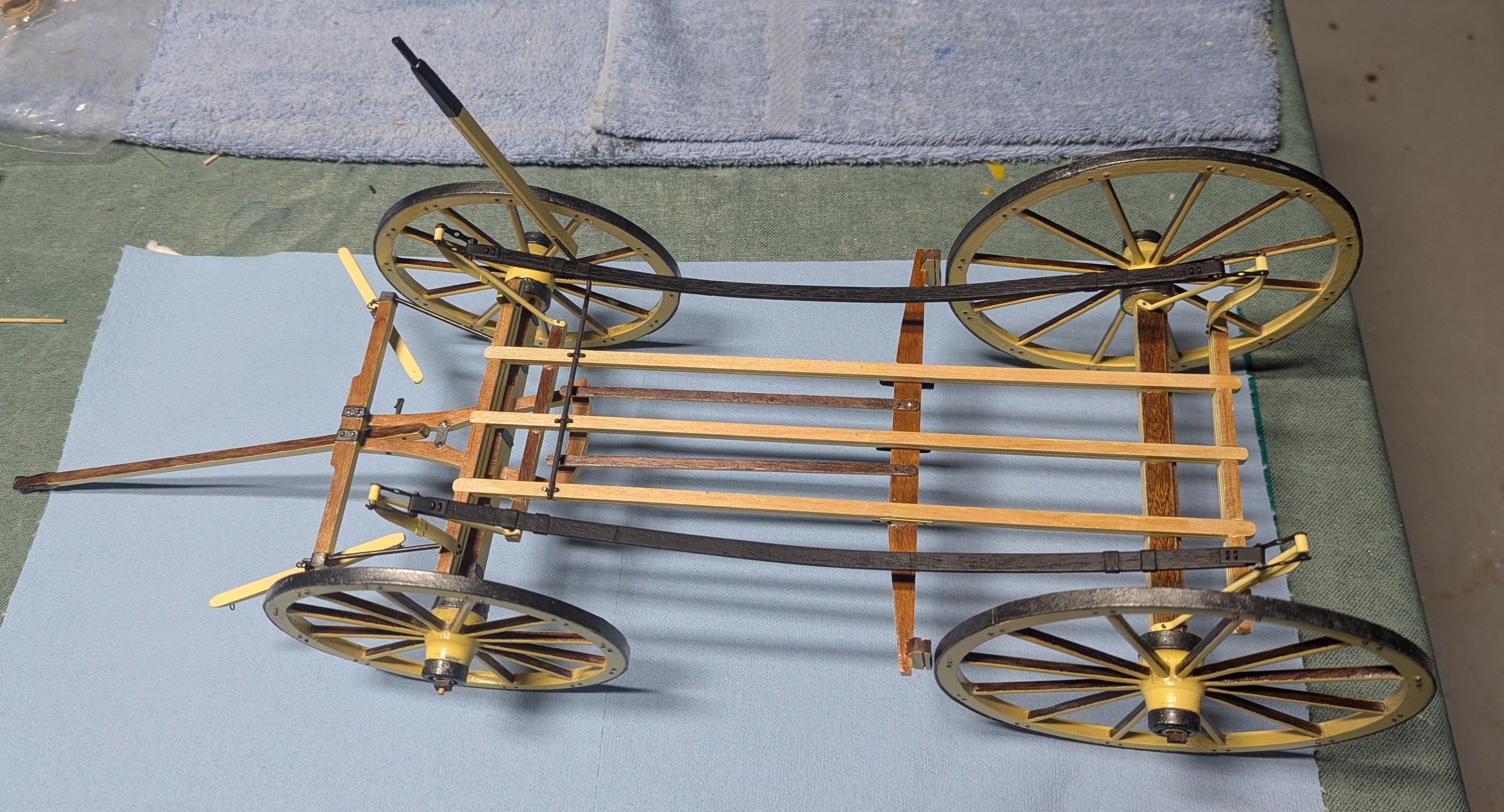
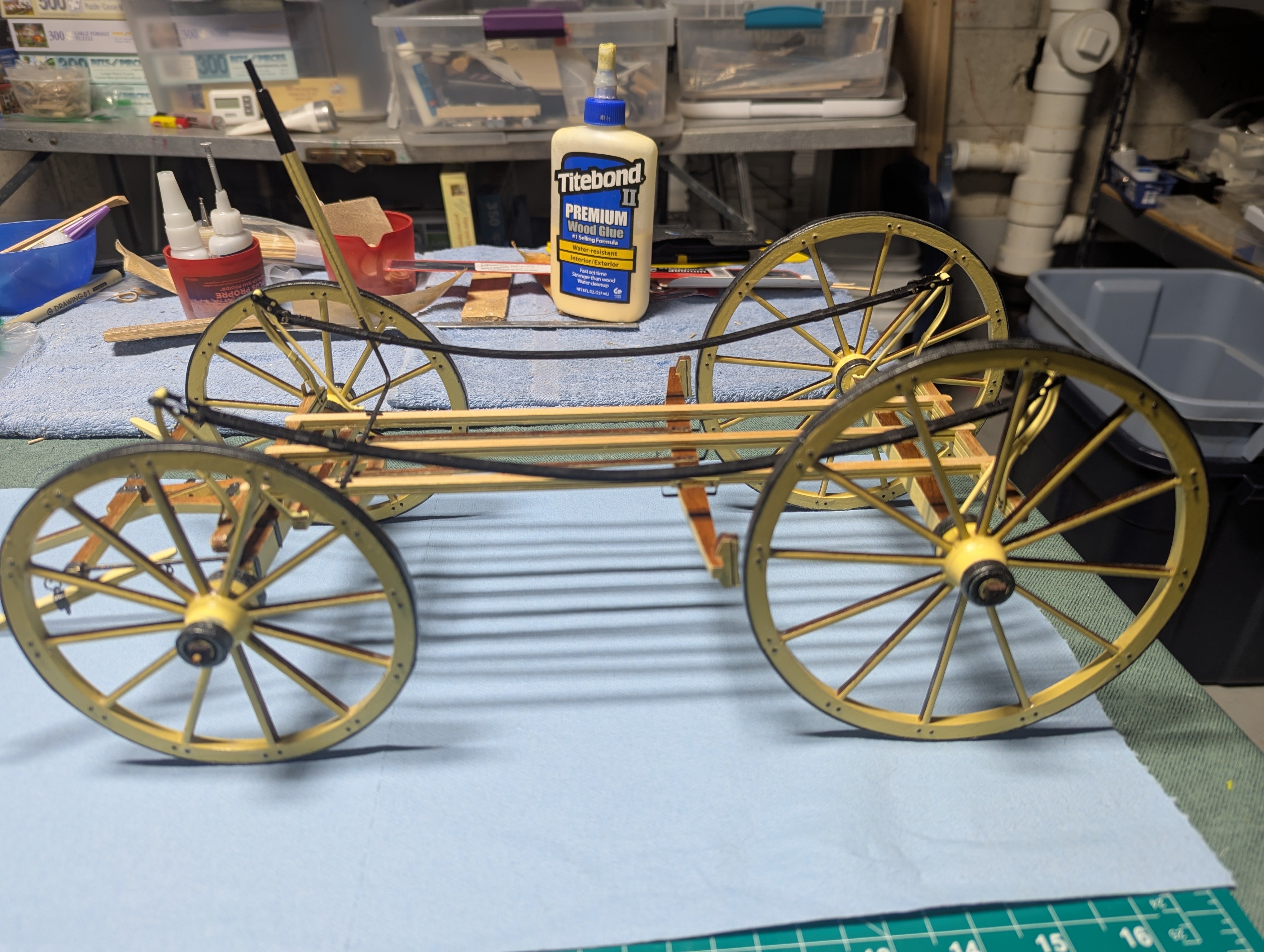
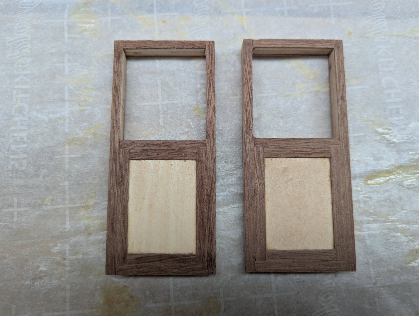
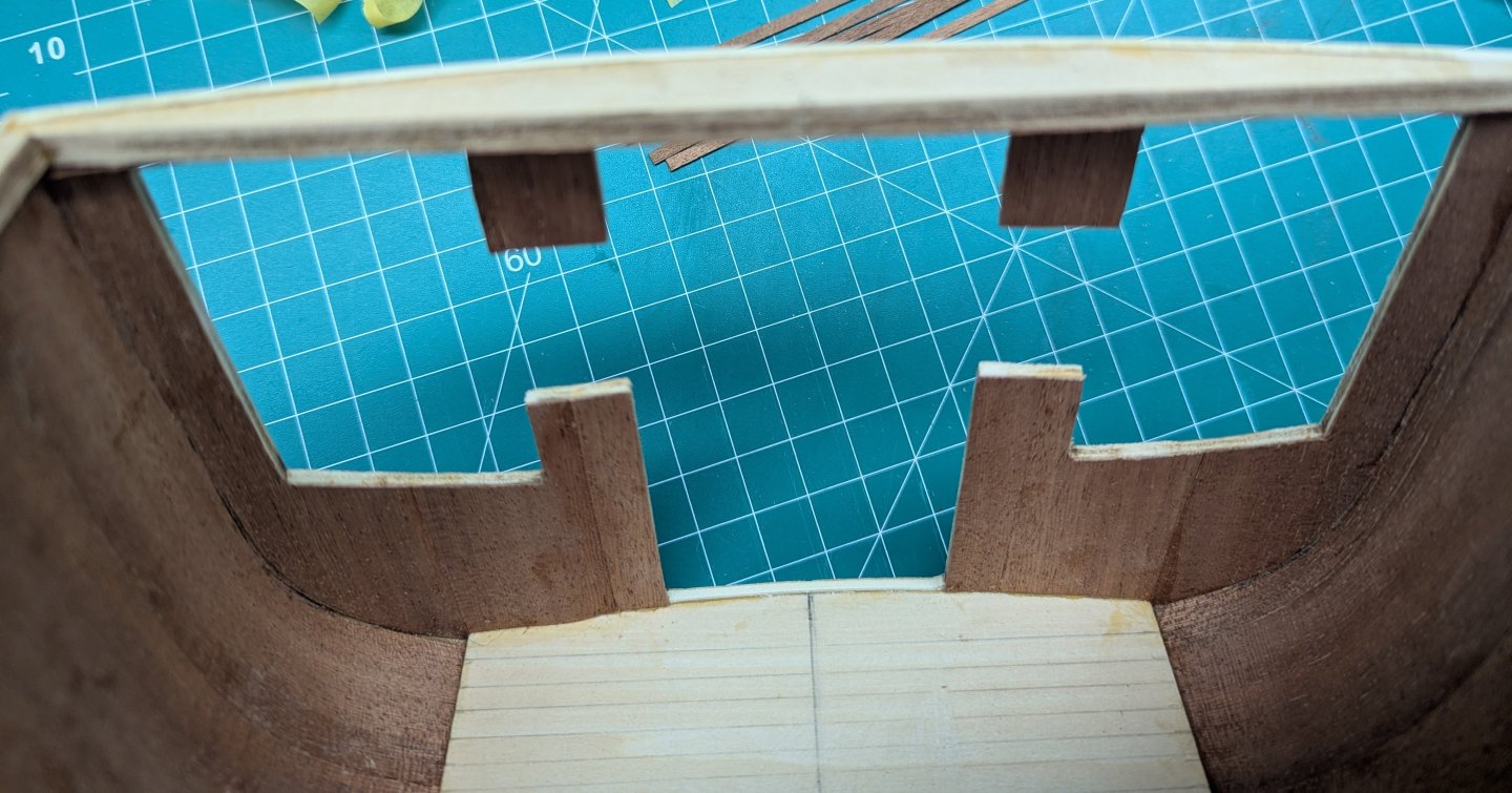
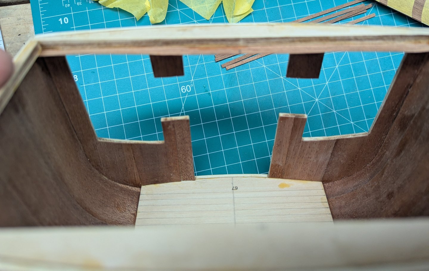
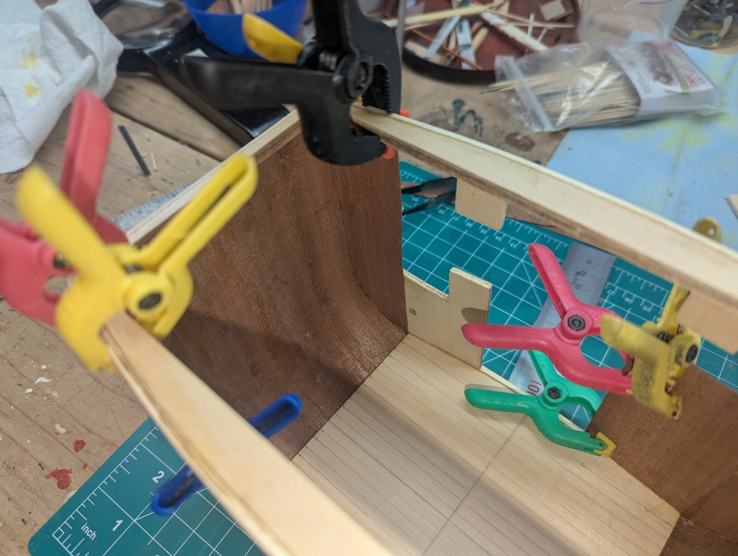
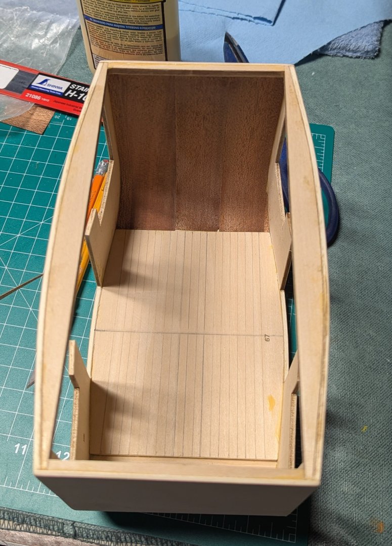
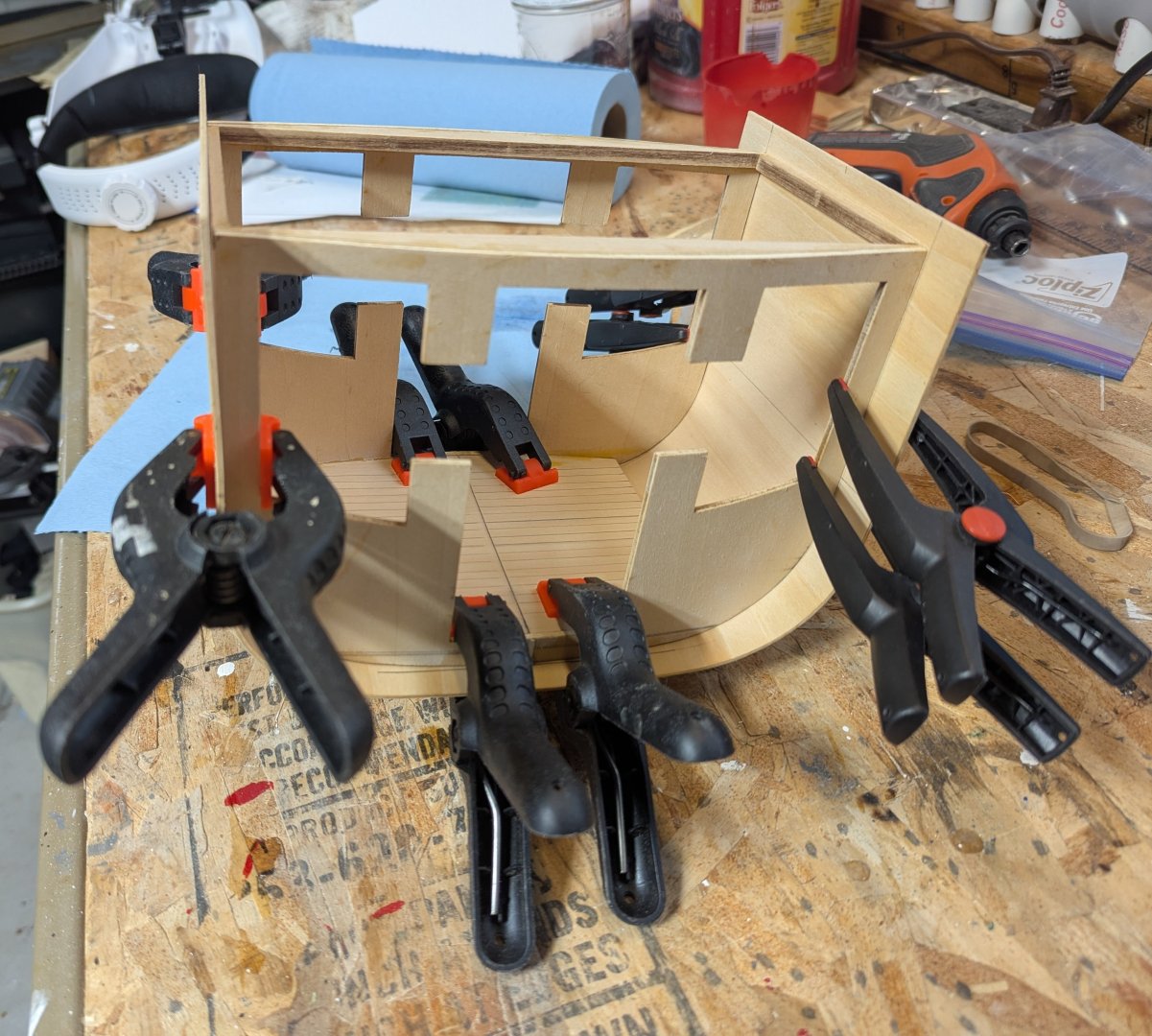
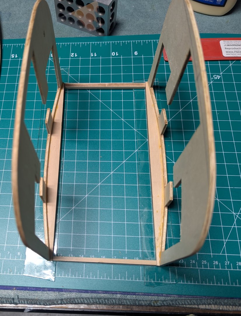
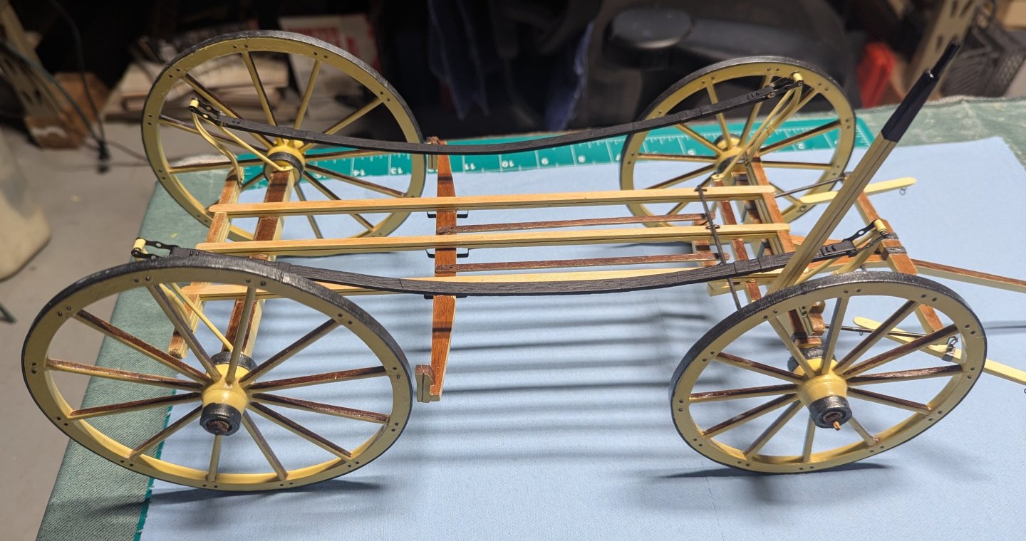
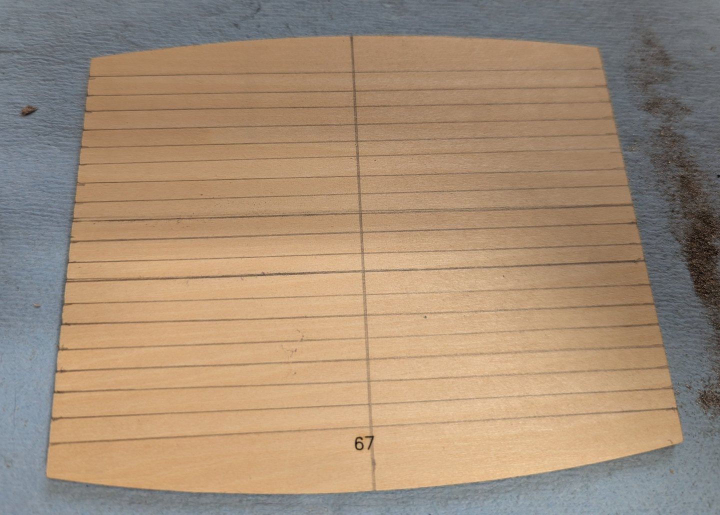
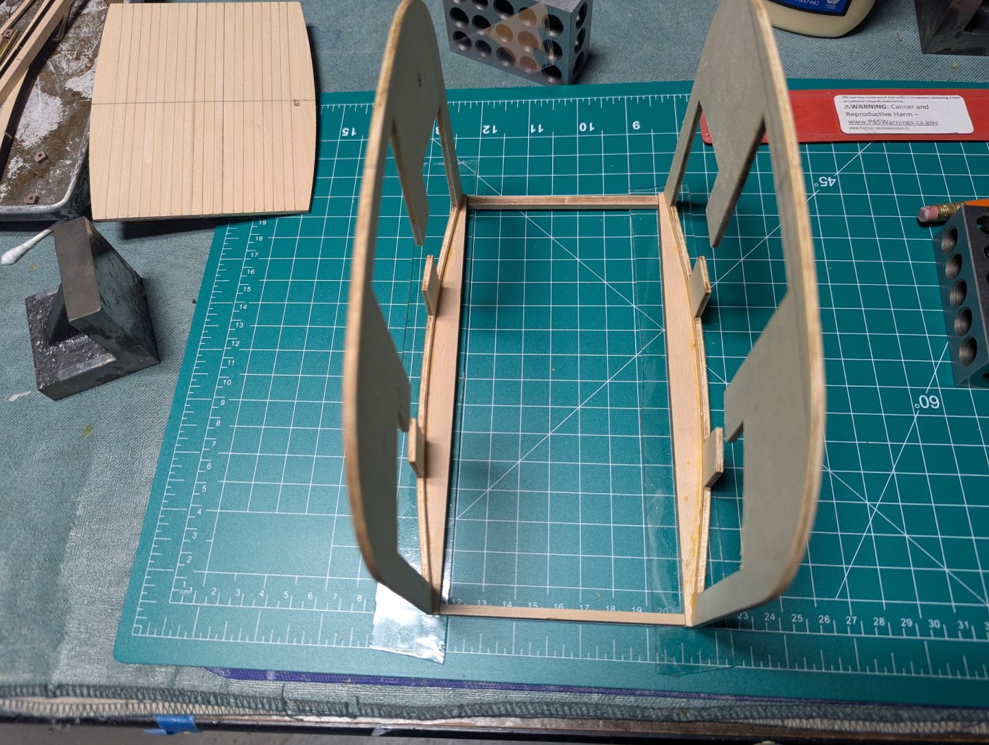
Final step for the frame is to add the previously assembled wheels and haul pole. And the frame is complete At this point the frame is complete.. It will be set aside, at the speed I build models, for a very long time while the carriage is built. Not required, but I choose to pre-bend the bottom half of the carriage by wetting it and using the outline the upper curved beams, let it sit over night. with both side pre-bent I joined them with the upper curved beams. At this point the instructions call to "glue on the floor".... Prior to doing that I drew some lines on the floor to give me a line of reference when later laying the floor beams. Lines are not any particular distance apart. They are just there to give a line of reference when laying the floor beams in a later step.


-
Really nice work so far...... Who says you can not have too many clamps? 🙂
- 71 replies
-
- 3
-
-

-
- grand banks dory
- midwest products
- (and 2 more)
-
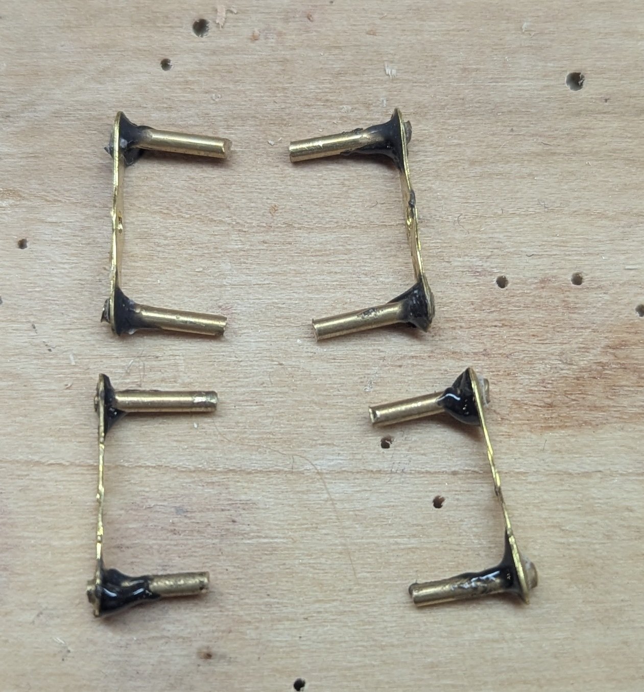
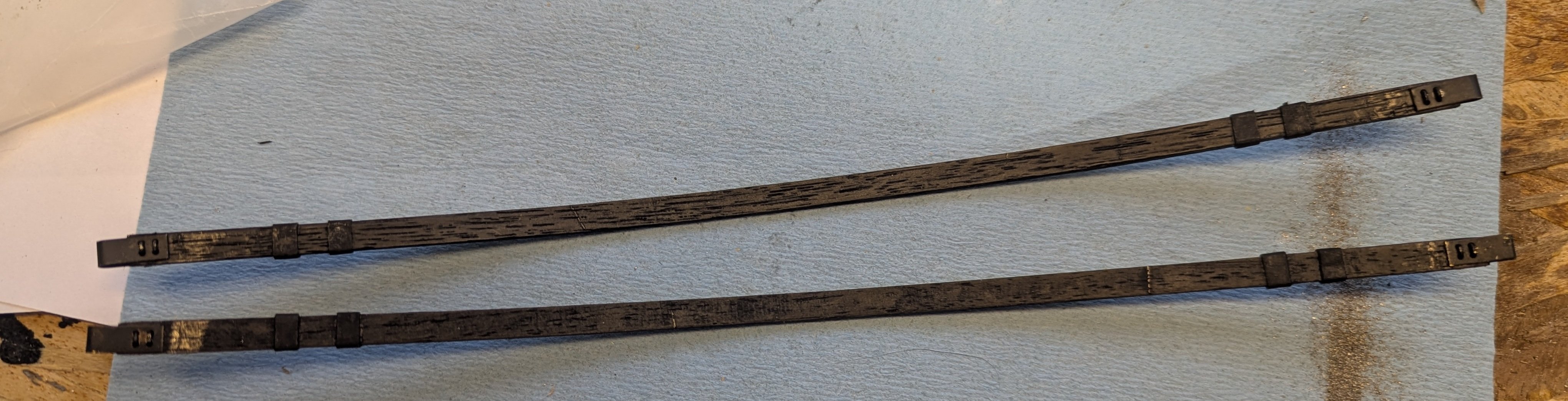
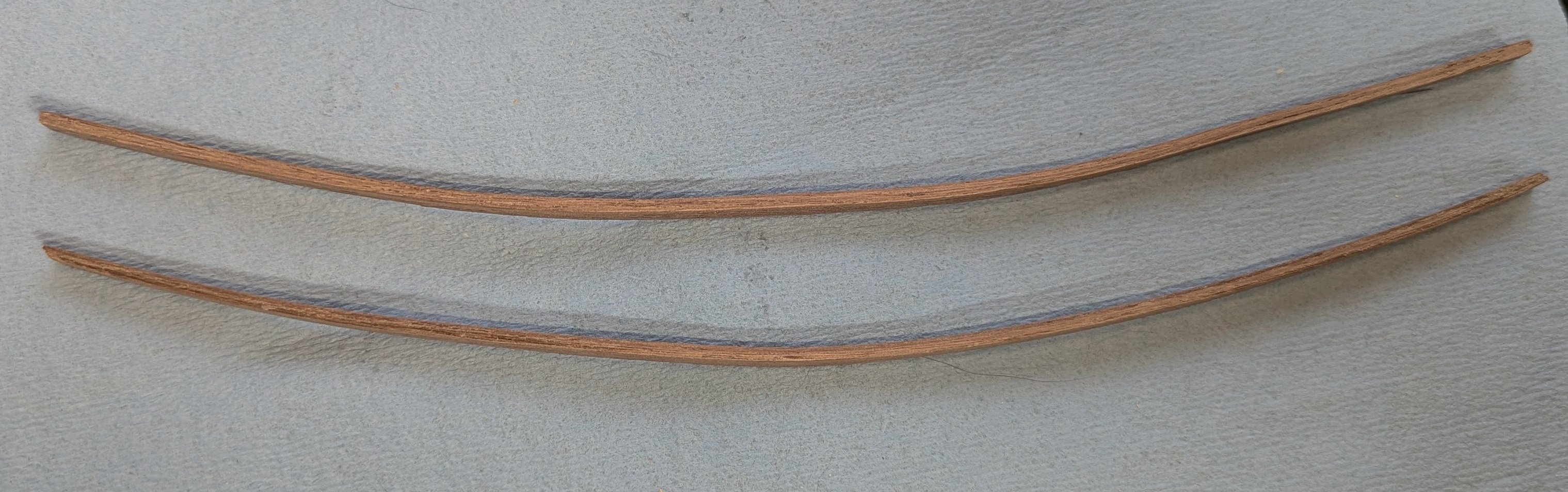
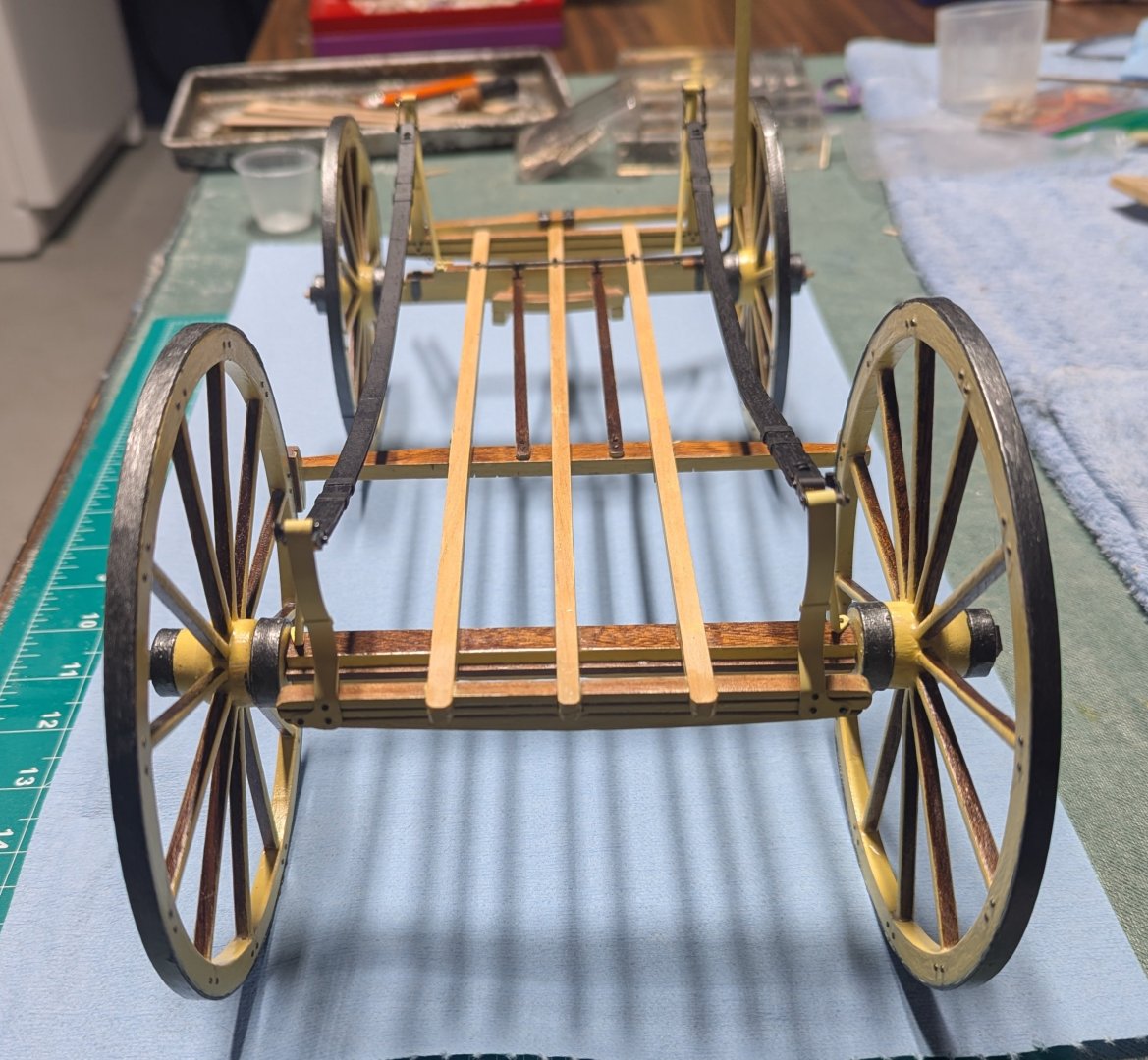
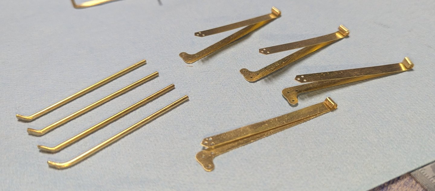
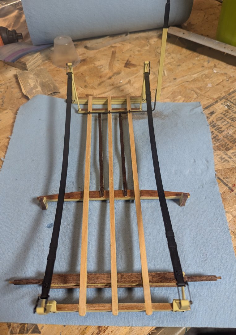
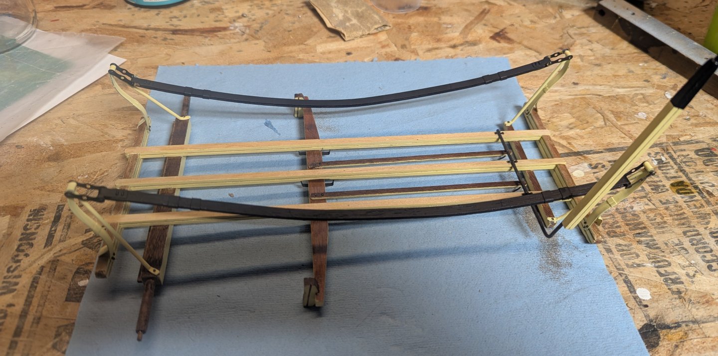
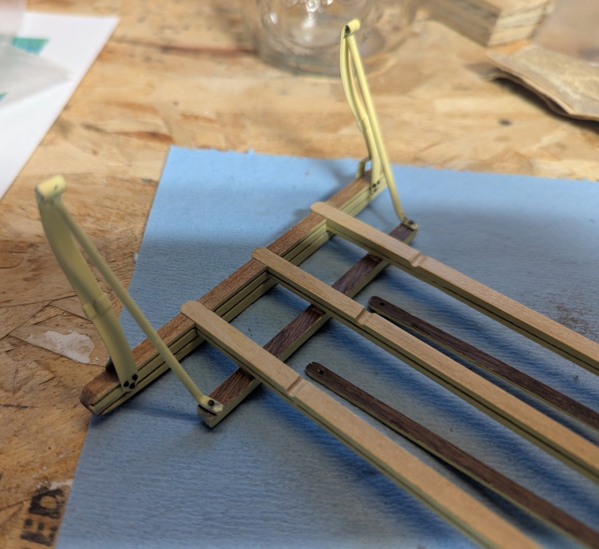
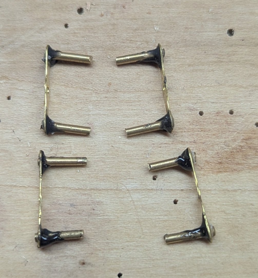
Creating the four frame exterior and interior brackets. This involves curling over the ends of each bracket and then inserting the interior bracket inside the exterior bracket. Note the resulting hole in the end of the combined brackets will eventually need to be able to fit a 1.5 rod. Before you are finished, make sure you can fit a 1.5 rod in the rolled hole at the end of the combined bracket. This will save you a headache later on. Making the suspension spring links, instructions call to use the etched brass parts and 1.5mm brass rod and attach them with CA glue. My problem was that the holes in the etched brass parts was a little larger then 1.5mm. Not sure the CA glue would really fill the gap and hold tight. Instead I used a tab of epoxy to hold the 1.5mm brass pieces. Epoxy not because there would be any stress on these joint, but more for it was thick enough to fill the gap. All would be painted black in the end anyway Bracket clamps attached to the frame after painting them yellow And then adding the black suspension springs via the suspension spring brackets
-
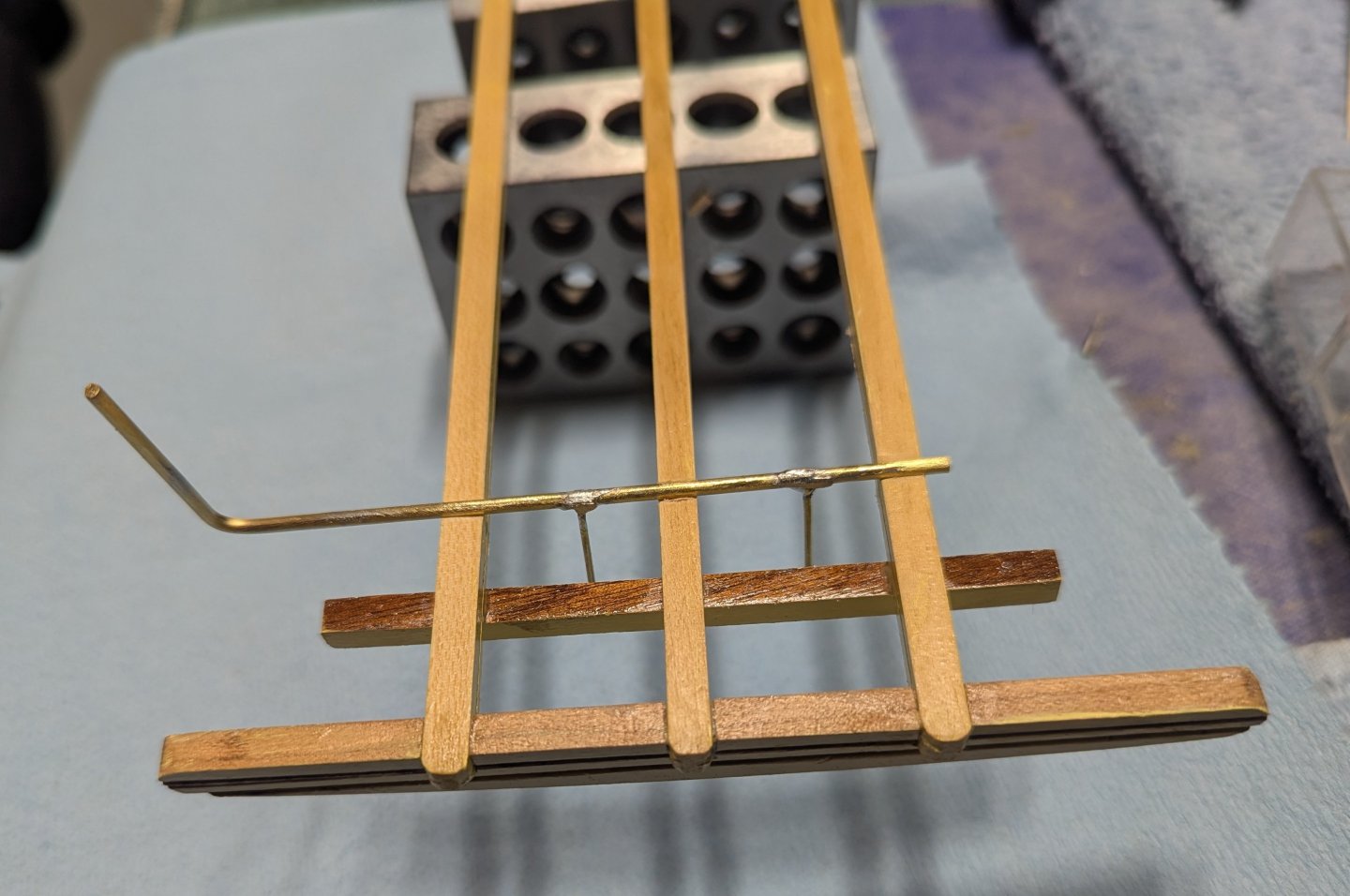
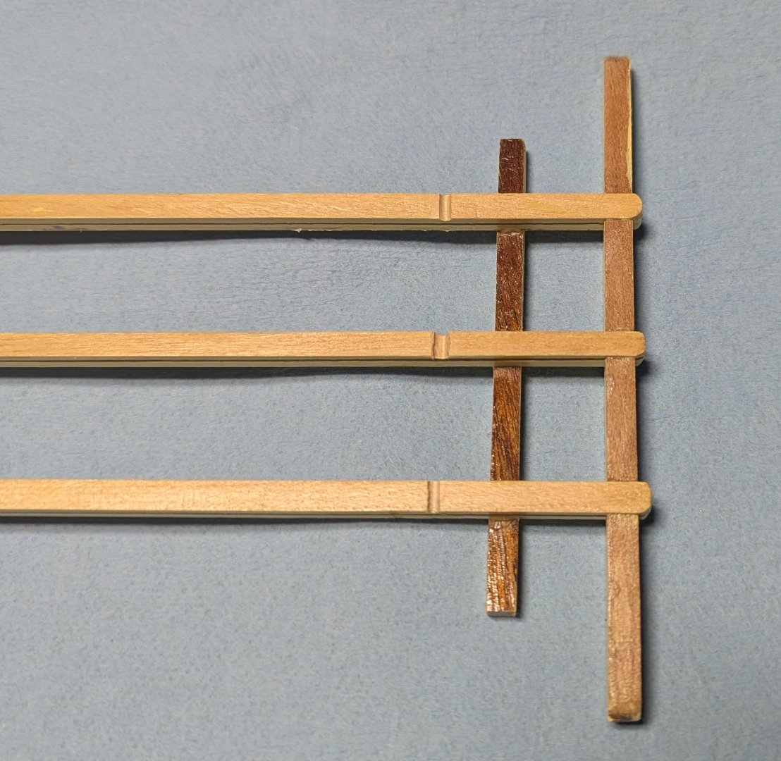
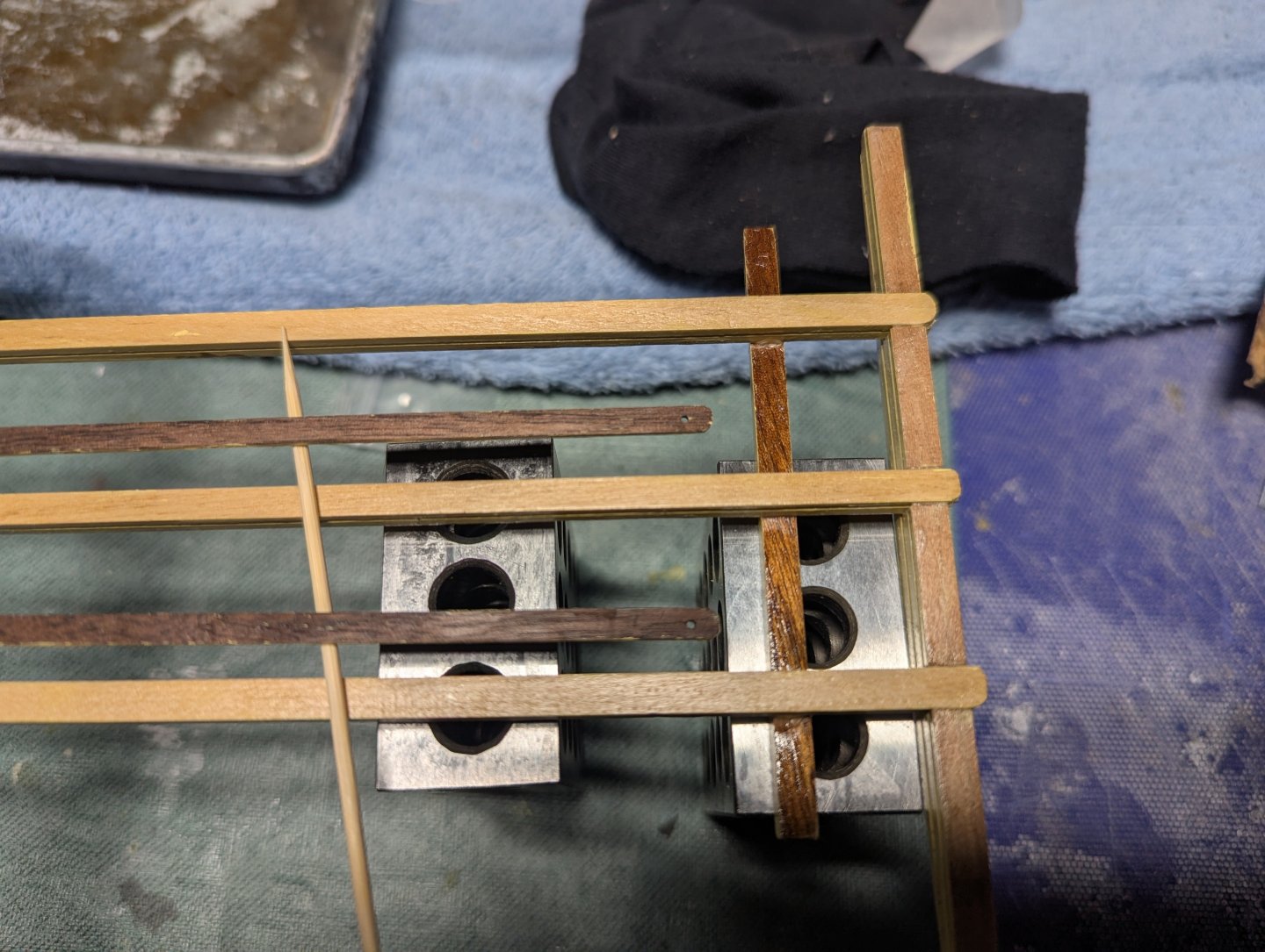
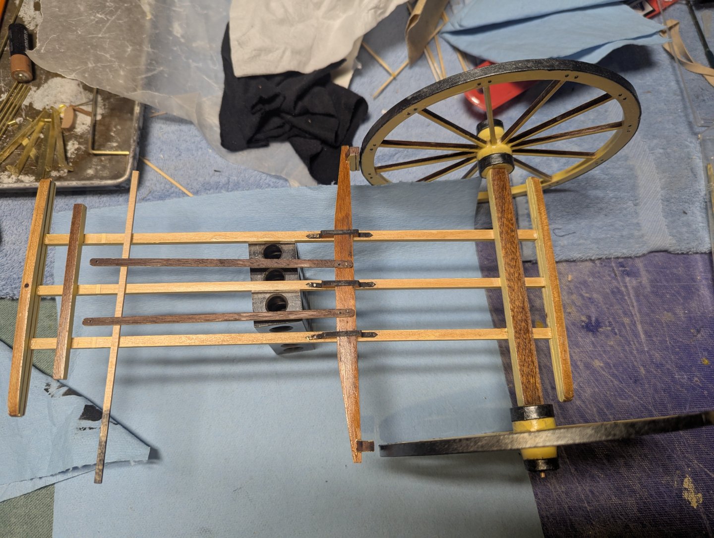
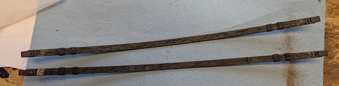
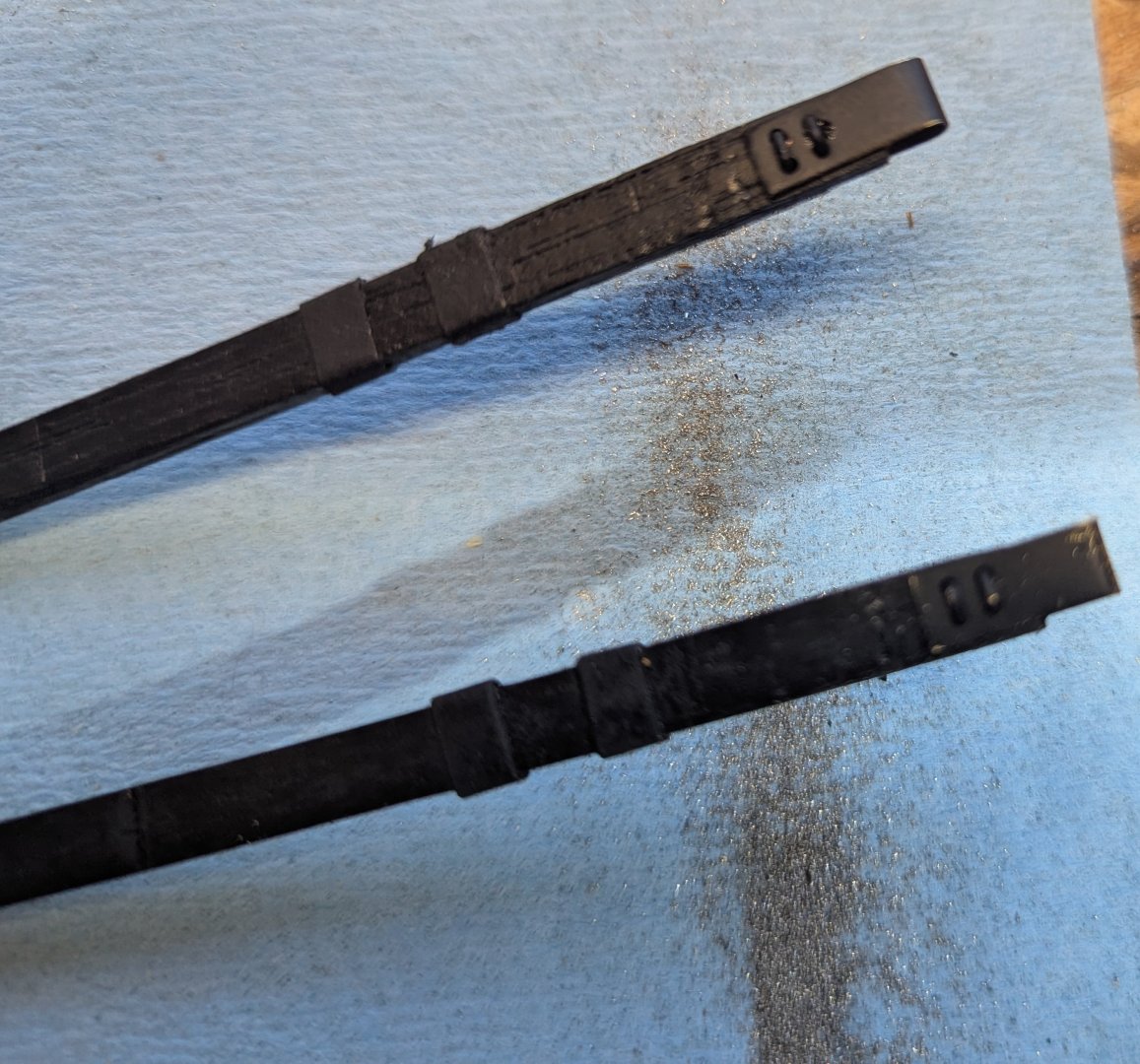
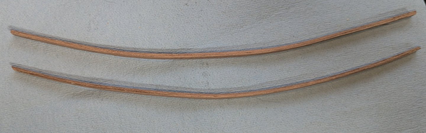
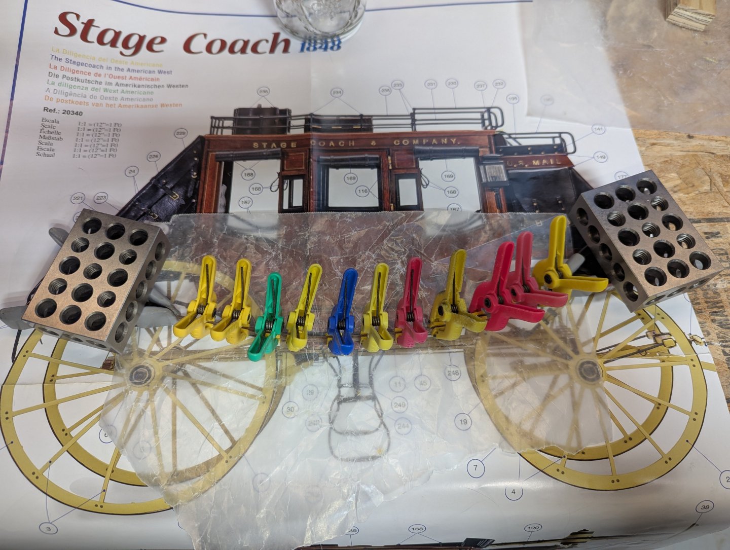
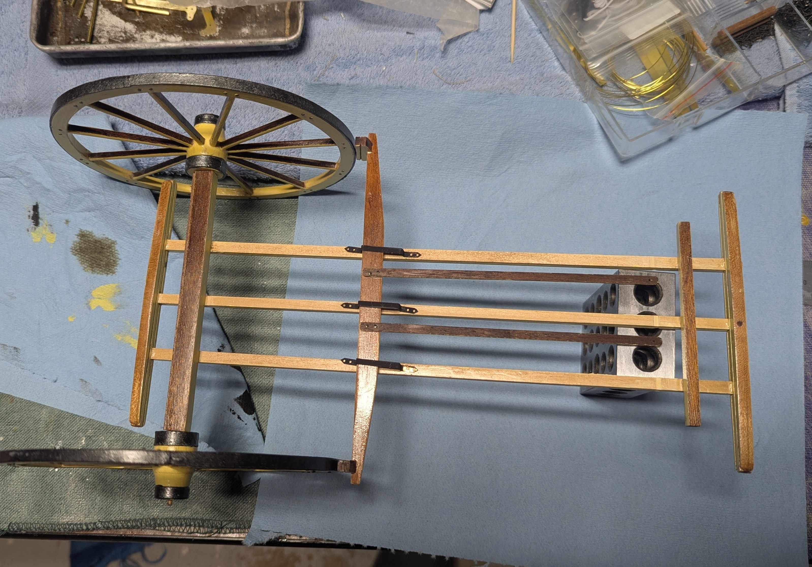
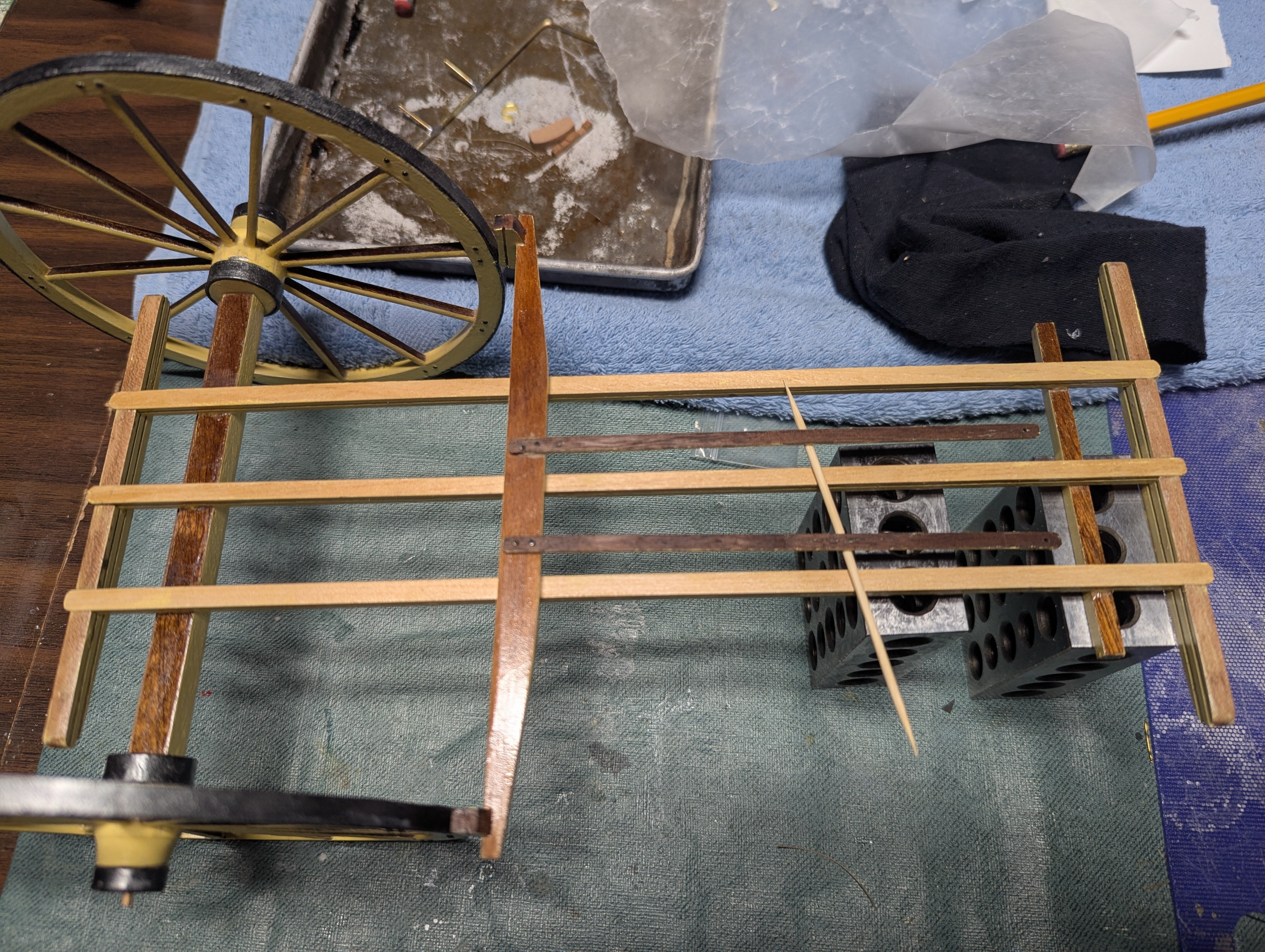
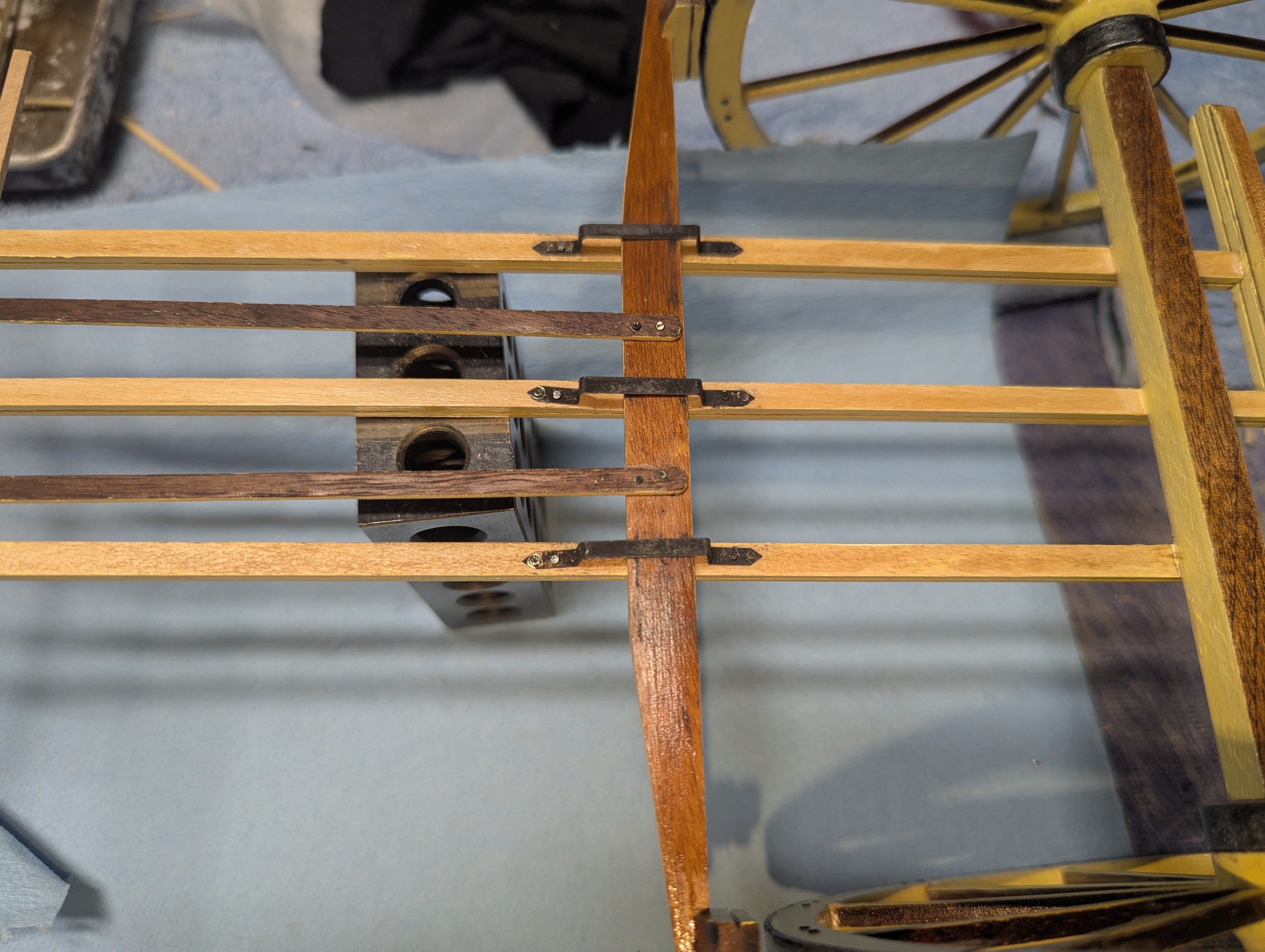
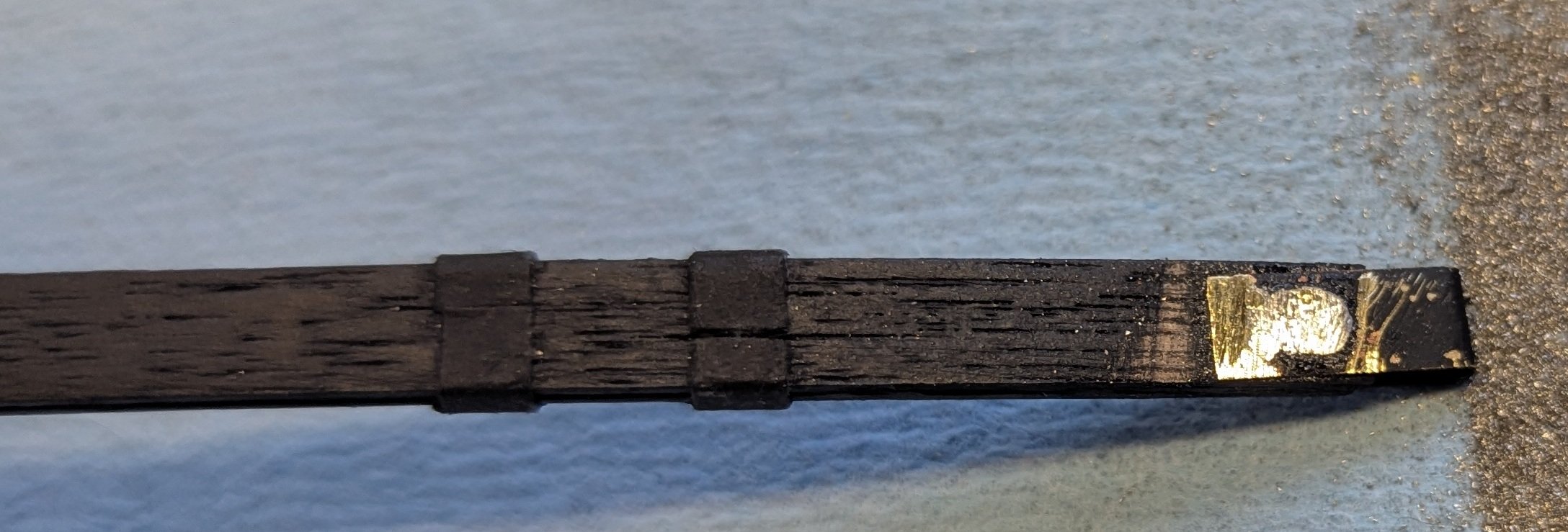
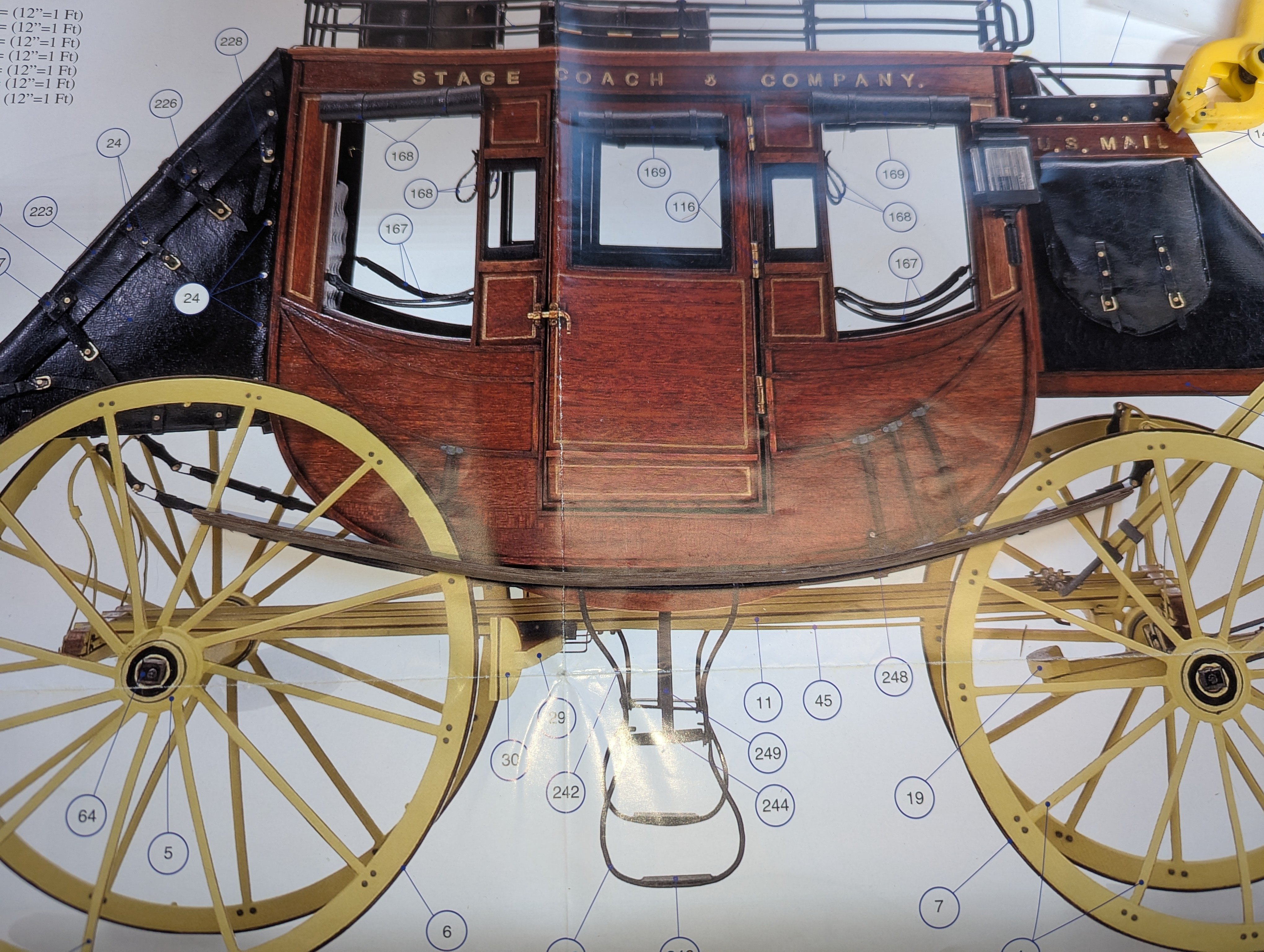
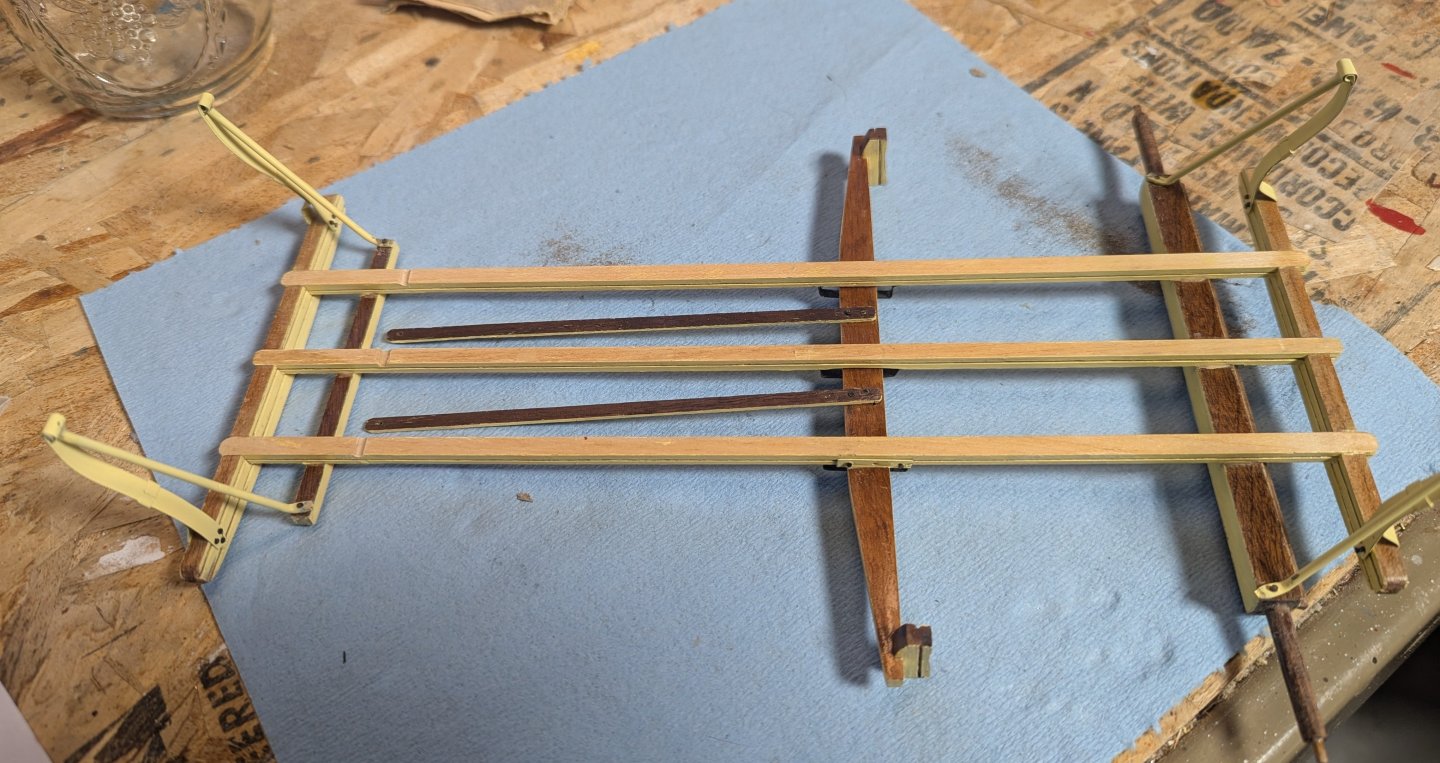
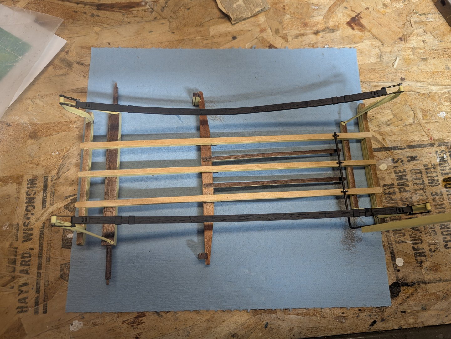
Next item is to figure out where the brake bar is located on the frame. Instructions call for it to be 24mm back from the front stabilizer. Not sure I would trust that measurement - especially with my modeling skills... Instead I temporarily put on the rear wheels, and with a toothpick holding up the brake struts, it is pretty easy to see where the brake bar should be located. Basically above the holes in the brake struts. Instructions do not call to cut a little channel in the three lengthwise beams, but the brackets (that attach the brake bar) are too small to fit around the brake bar, so you really have no choice. From the measurement above, mark the lengthwise beams adjacent to the holes, and with a drill bit, create a little channel to hole the brake bar. Use the brackets that are used to attach the brake bar as a guide as to how deep the channel needs to be. When all is done, brake bar should easily fit into the three lengthwise beams. Brake bar only now needs some blackening. Next the three brake bar rails were formed to shape and located on the three lengthwise beams. Again temporarily attach the rear wheels and position the brake to locate the position if the brake bar rails. Once located, blacken them and nail to the beams. Next came the suspension springs. In order to get close to the actual curve I used the "actual size" diagram to form the curve. I put the "actual size" in quotes as I assume do to camera angles and what not, the pictures are not really actual size. I mentioned the earlier, the picture are close but in reality a little larger then actual size. But close enough in this case. After soaking the suspension springs, who says you can not every have enough clamps? Let it dry over night, and you have your suspension springs Paint them black, add the fitting on the ends. Not the fastening wires in the end of each spring. Instructions state they are the 10mm wire bent over and thru the spring. On the other side of the spring the end are soldered and sanded, and eventually painted black Below is the other side. The four wire ends have been soldered and sanded smooth. Just need to touch up the black paint.