HOLIDAY DONATION DRIVE - SUPPORT MSW - DO YOUR PART TO KEEP THIS GREAT FORUM GOING! (Only 24 donations so far out of 49,000 members - C'mon guys!)
×


John Gummersall
-
Posts
265 -
Joined
-
Last visited
Content Type
Profiles
Forums
Gallery
Events
Everything posted by John Gummersall
-
 Brian, That is a good comment.... And it would be like me to forget that. But fortunately this time I did not. Before I masked the sky light I located where the Texas cabin would be located and laid down the wood foundation to support the walls. Then I laid down the masking tape and painted around where the Texas cabin would be formed.... I will say, there is one issue with the masking tape method.. On the Boiler deck the stationary holes around the edge are square (to accept the 1/16" stationaries). But unless you have some sort to square drill (and I do not), to free up the holes (covered by tape) you have to drill or poke them out,,,, and they end up more or less round. But when I comes time to put in the stationaries, square wood is close to round, and with a hold that small, the square wood fills up the hole and it is not noticed.
- 157 replies
-
- 4
-

-
- chaperon
- Model Shipways
- (and 1 more)
-
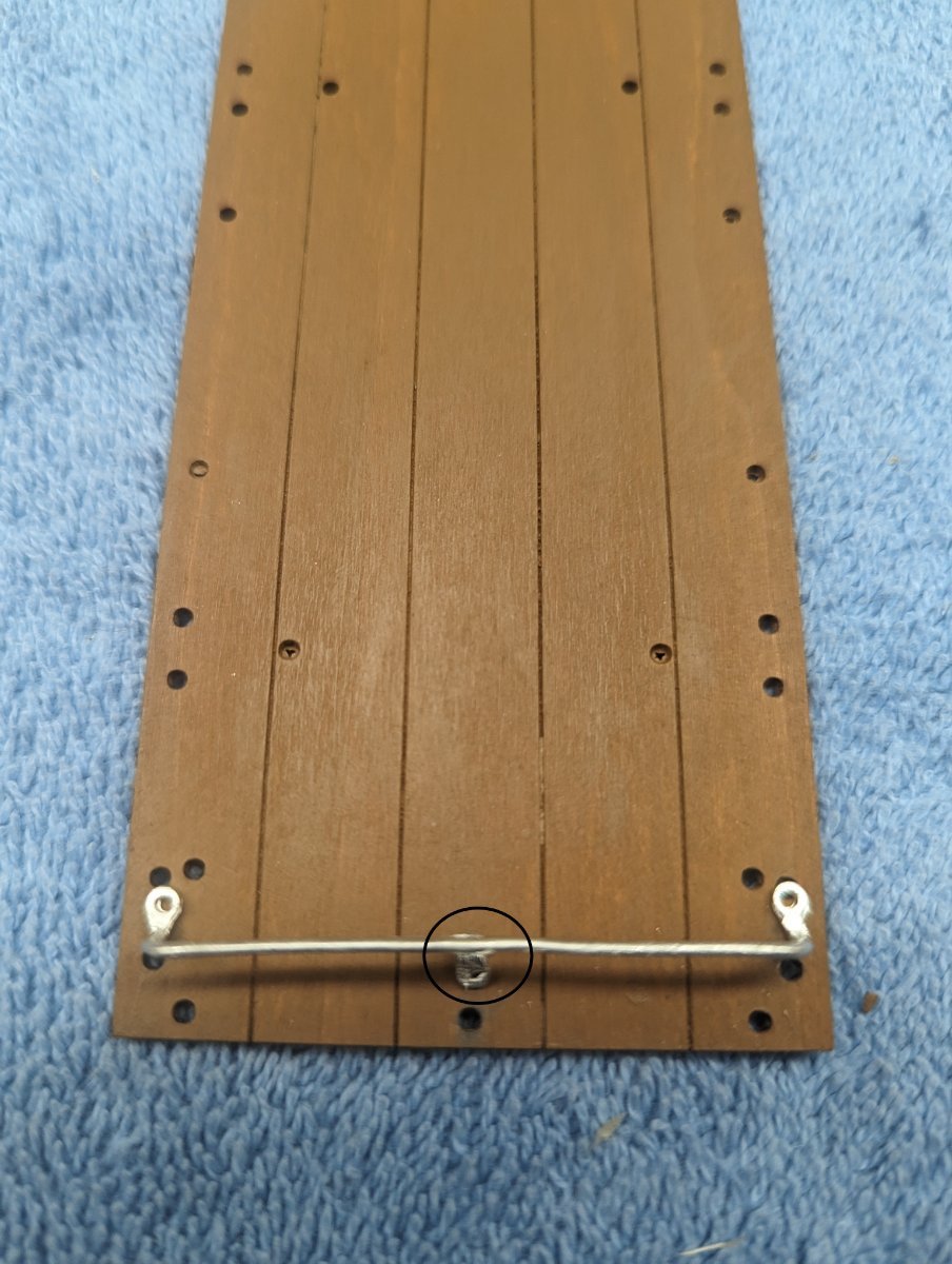
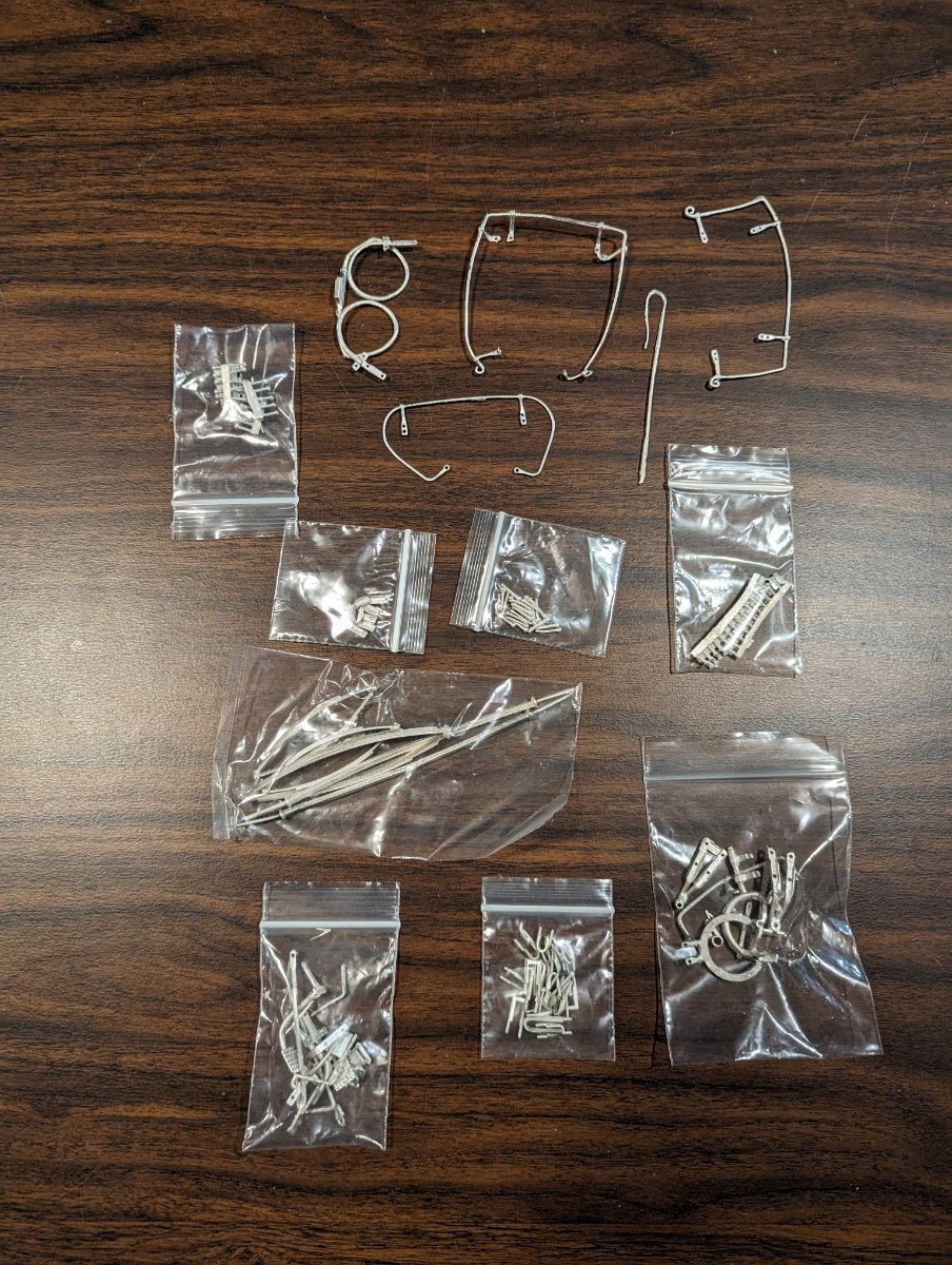
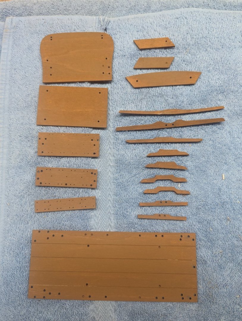
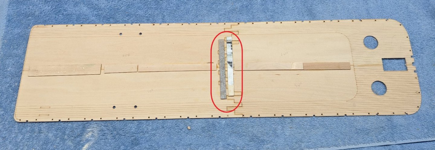
Earlier I said I was not going to start this build until end of October....and that is mostly true,,, But just could not help myself. I just had to open the box and do a few initial things. Started out by cleaning up the char marks and staining the most of the wood components. Only wooden spokes and wheels are still in the box. There are so many spokes, I figured by the time I got the that part of the build I would have lost some of the spokes. Here are the non-wheel wooden parts Started cleaning up the Britannia metal parts. As mentioned earlier this will be the (shall we say) "interesting" part of the build. Anyone who has worked with Britannia knows what I am about to say... UGH.. As with most Britannia parts, the metal is soft and does not come easily out of the mold when formed at the factory. As such, many of the parts are mis-shaped and/or have rough edges that need to be cleaned up. I would say with this model the Britannia is as you would expect... no better and no worse than any other Britannia parts on other models. Since many of the parts are mis-shaped, I would suggest as you clean them up, to look on the plans and try to bend the part into (more or less) the correct shape before you prime and paint it To me, doing all the bending after the part is painted, could tend to knock off some paint and require touch-up. I will say that some of these Britannia parts will be somewhat of a challenge. Most of the Britannia parts are to be "simulated" bolted to the wood chassis. As you can see the chassis clearly shows where the parts will be placed. And the parts have the holes drilled into them. Problem is, being Britannia parts, many of the holes in the parts are mis-shaped and/or or never formed properly in the mold, In the part below I have positioned it close to where it will eventfully be placed. The part (circled below) shows both outer holes pretty well formed, but the circled part hole is complexly filled in with metal. Normally drilling out the hole would not be a problem, but the mis-shaped part is only a little bigger than the hole I need to drill. I give that hole a try, but I have a feeling the part will break, and I will have to "simulate" a bolt running through it. In the end no one will be able to tell the difference but it would have been nice to have the part large enough to drill the correct hole size. I won't show other parts with this same issue, as you get the idea, but it looks like there are a number of parts that will need their holes drilled. I just we just chalk it up to "fun with Britannia" 🙂

- 19 replies
-
- 11
-
-

-
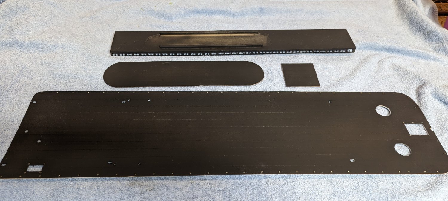
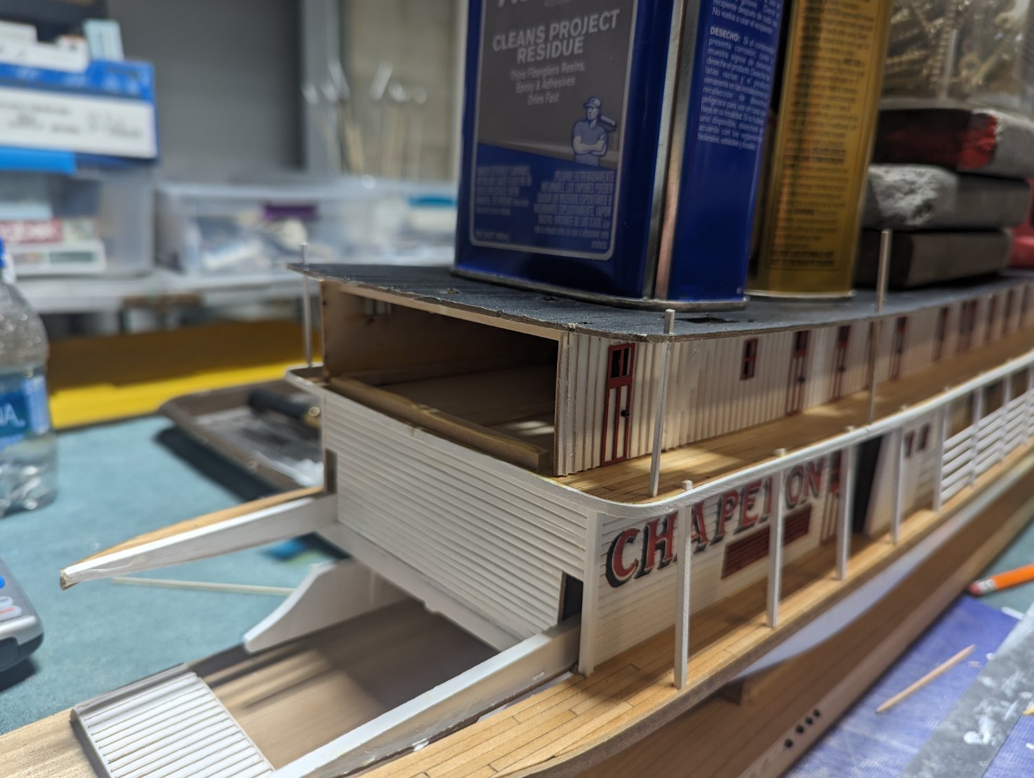
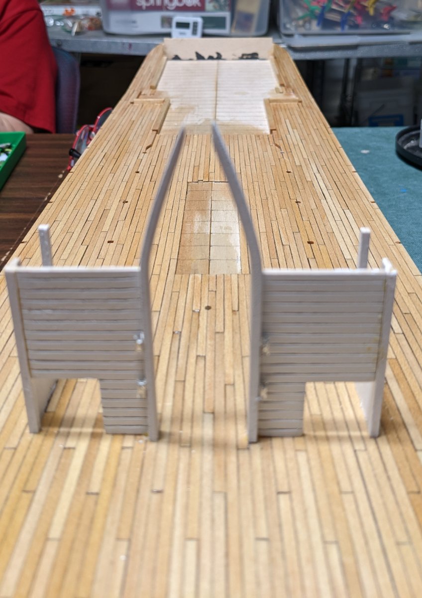
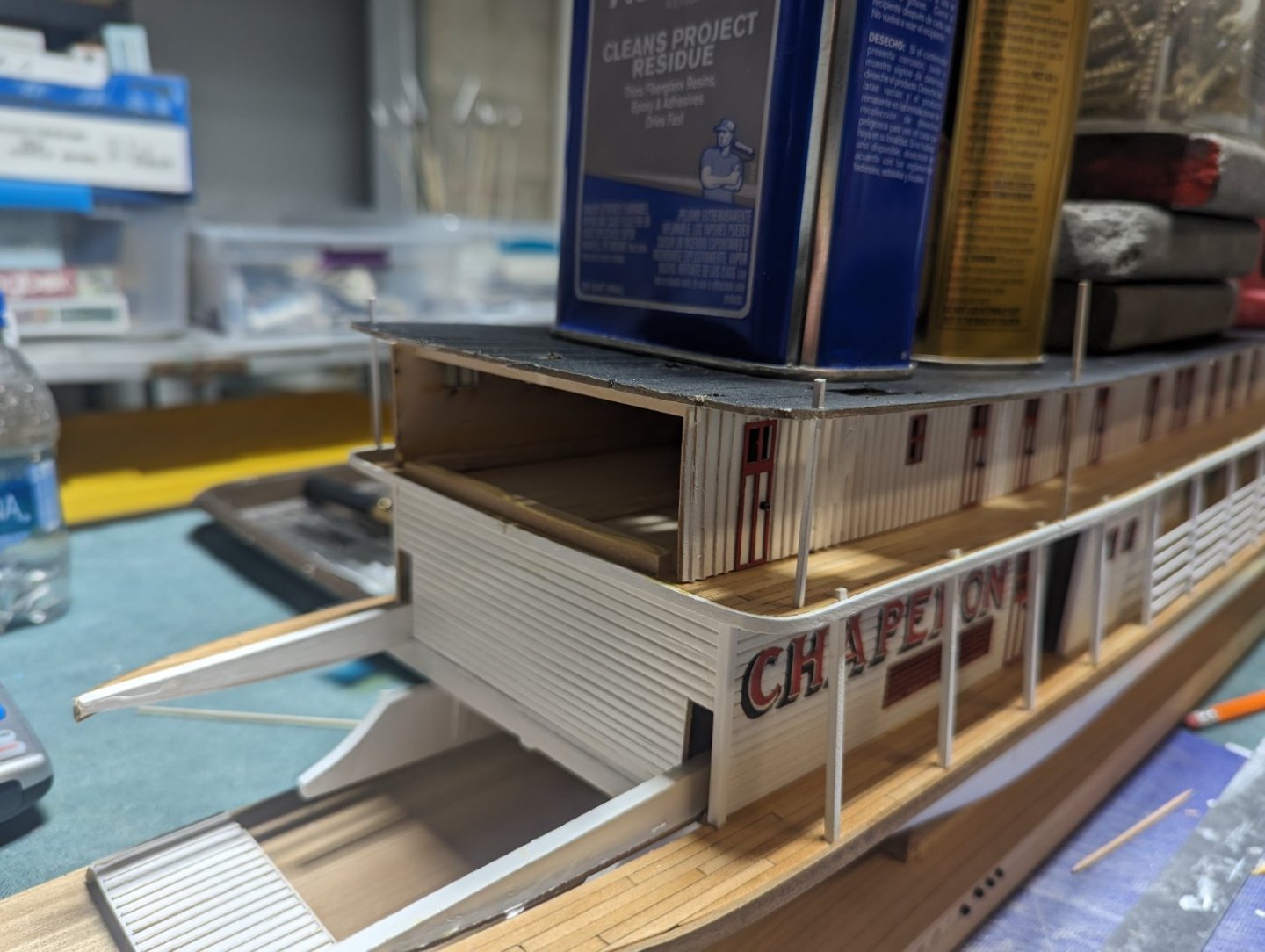
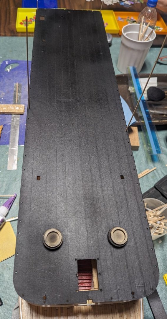
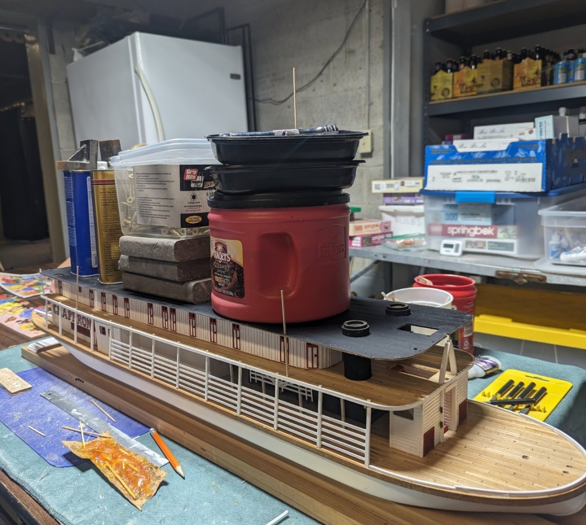
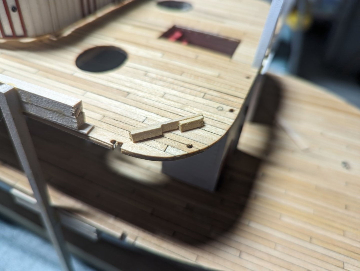
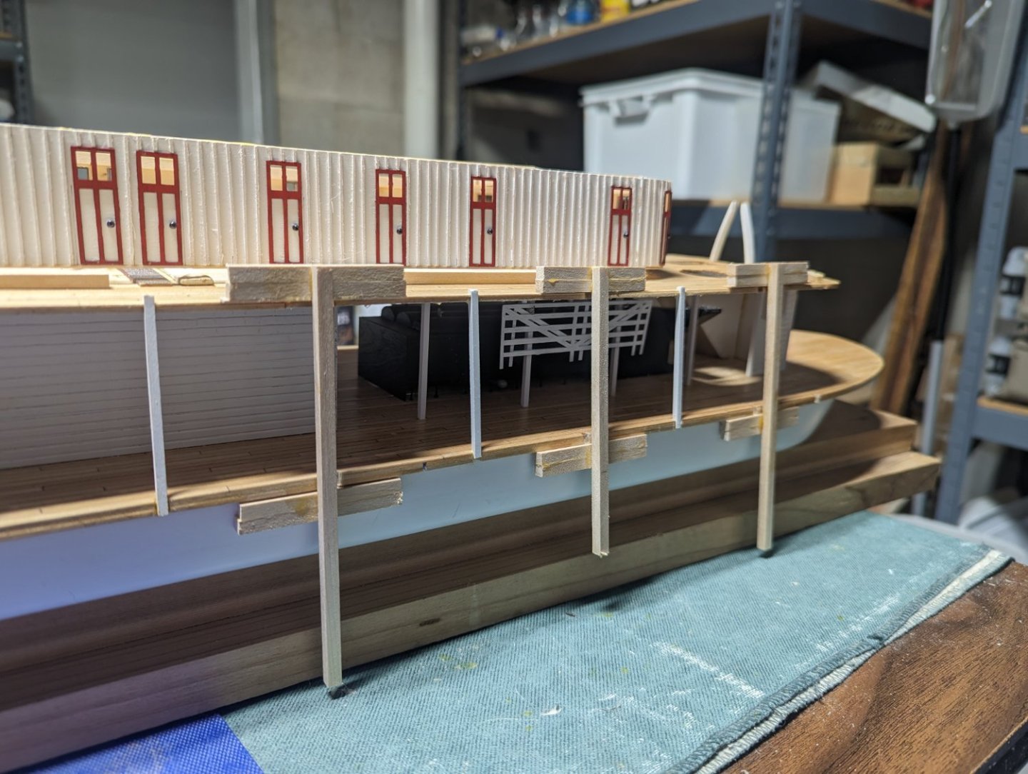
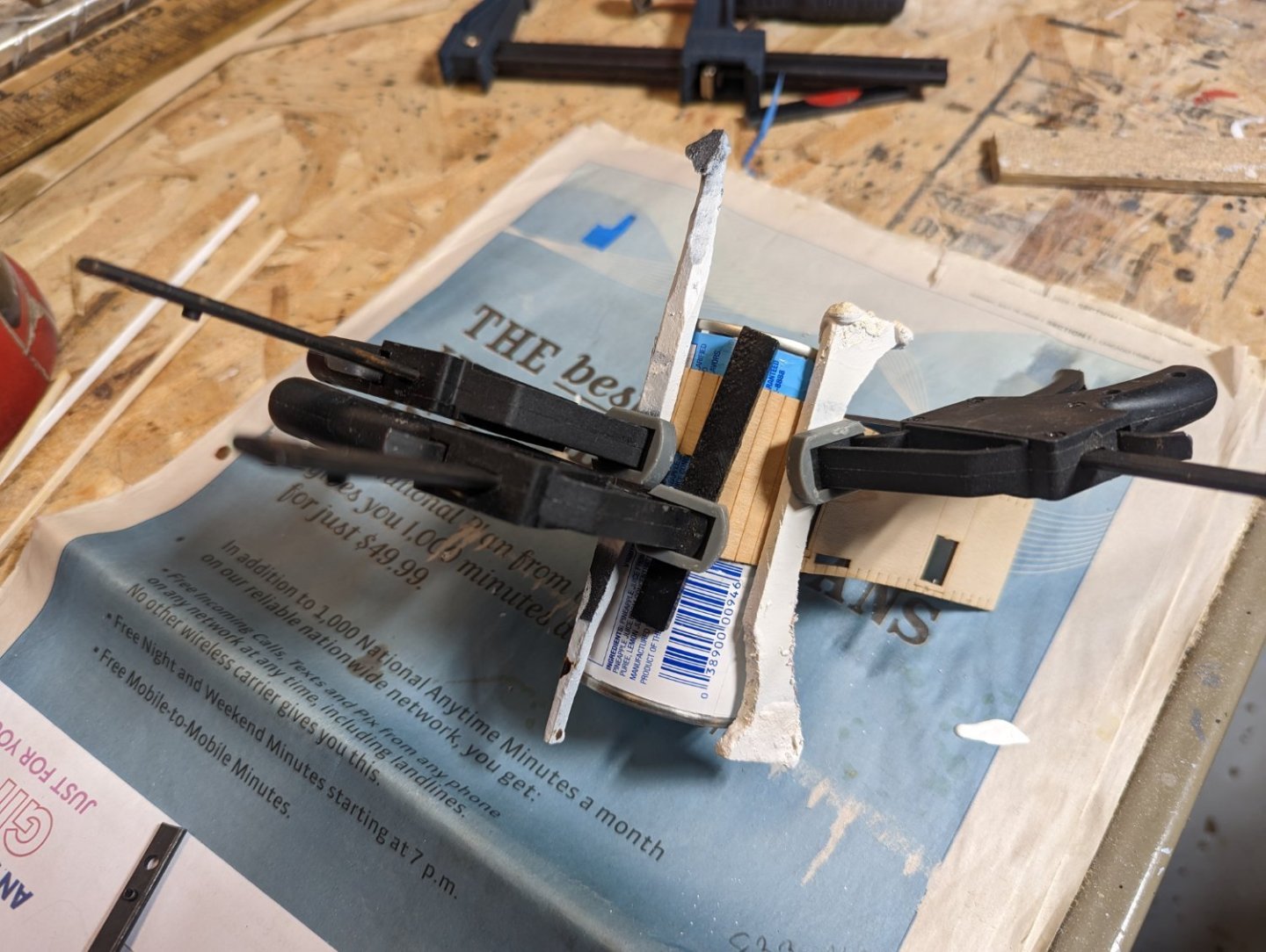
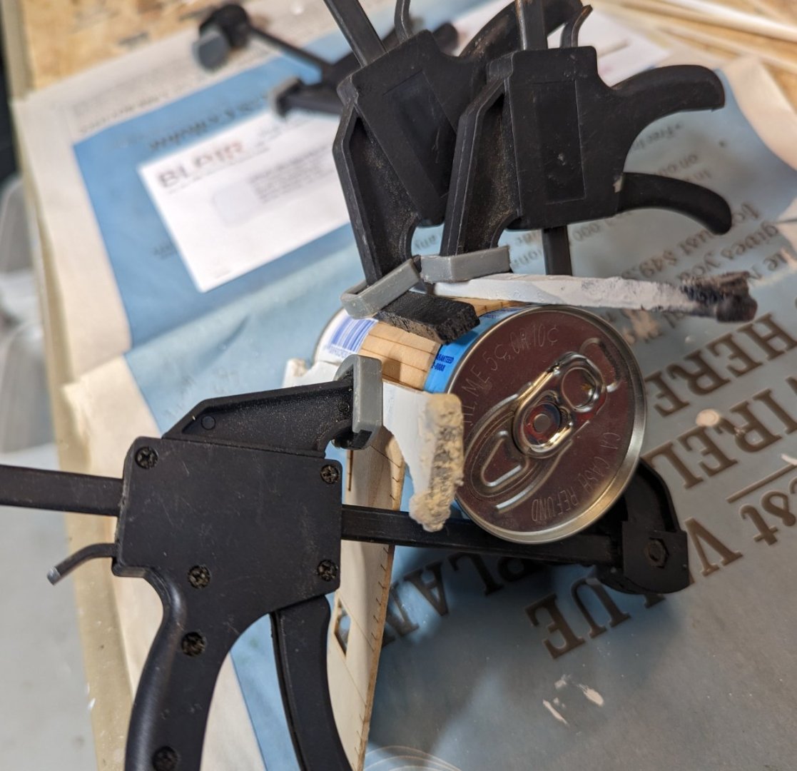
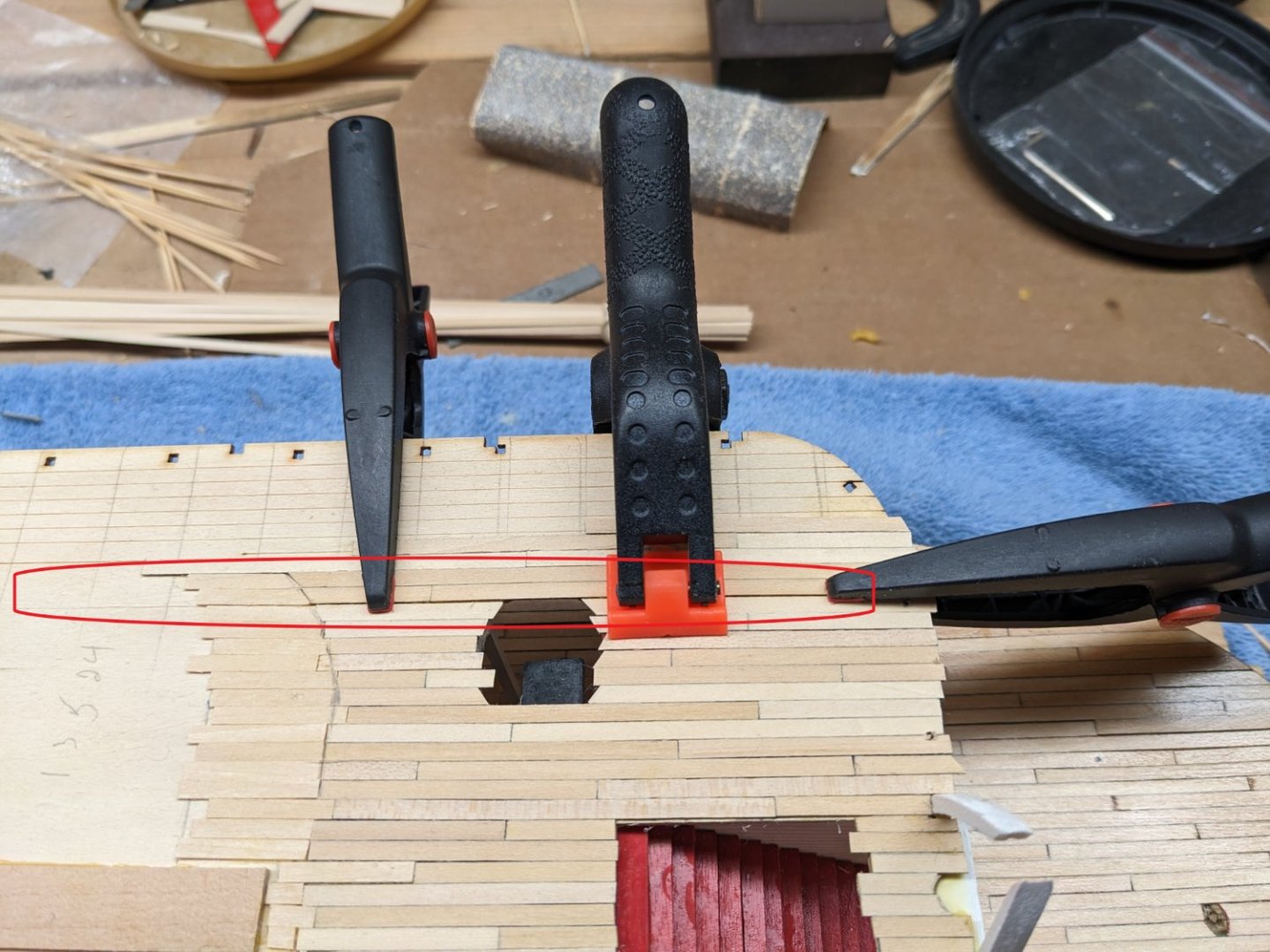
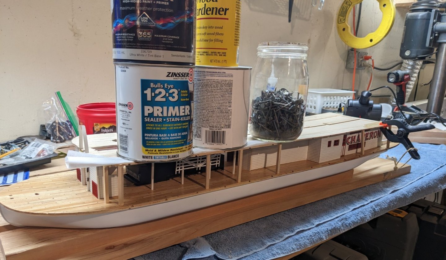
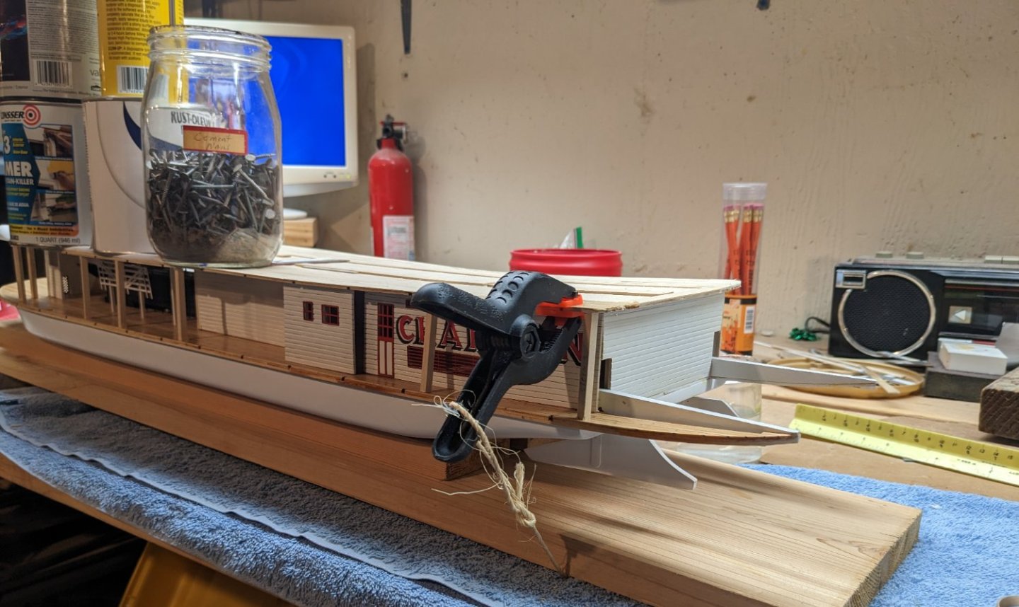
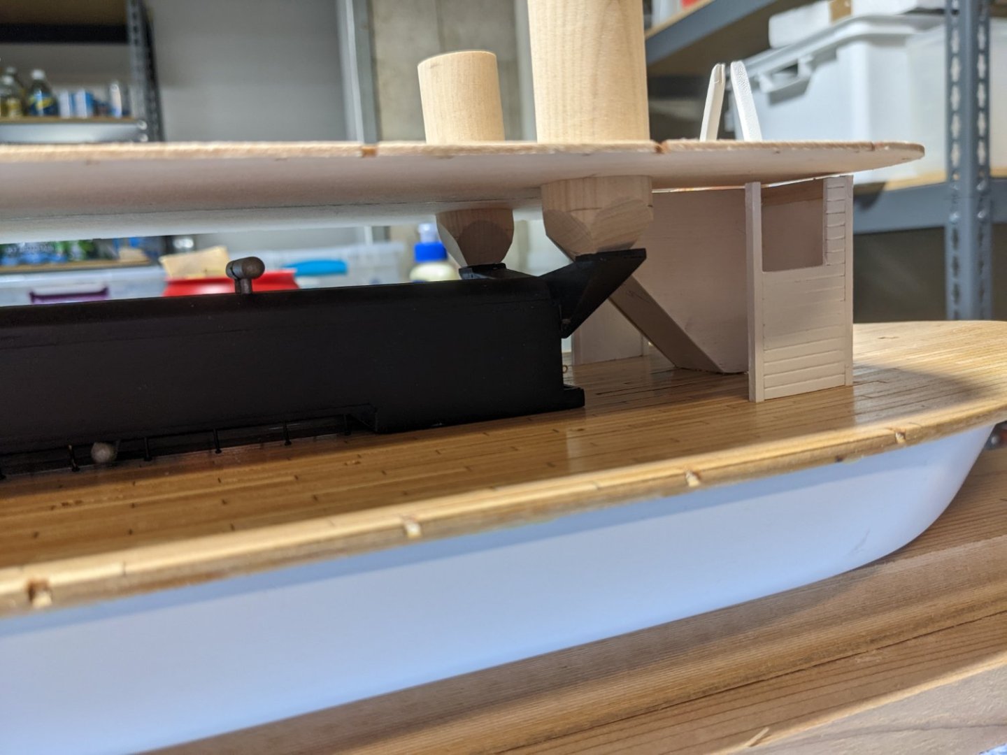
Onward and upward... At long last the hurricane deck is finally ready to glue. All holes have been enlarged and ready to accept the corresponding parts that come next. As for the simulated tar paper strips, I think the masking tape idea worked out OK. As indicated earlier, at my skill level I do not think I could have pulled off silk span or tissue paper methods. A couple of points for those of us less skilled,,,, The instructions call to glue the forward stairs, from the boiler deck to the hurricane deck before gluing down the hurricane deck. In my opinion, no way would I be able to pull that off and have the stairs align properly with the hurricane deck. If those stairs were glued down prior to the hurricane deck, with all the alignment (shall we say) "fun" lining up the hurricane deck with the stationaries, it would be too much to hope to assume those stairs would be in the correct position. Instead, since the hurricane deck overhangs the boiler deck, will be an easy effort to just slip in the forward stairs after the hurricane deck is glued down and before the stationaries are inserted. Below is a show showing plenty of room to insert the stairs and secure them down to the proper size prior to the stationaries. Same issue with the boiler deck back wall. Instructions call to glue down the back boiler deck wall when you glue down the boiler deck structure. In the below picture, neither the back wall or hurricane deck have been glued down. As you can see, the edge of the back wall should align with the last stationery. In theory, if you were every accurate with the bending of this wall, it will align with the last stationaries. But if that bend was not exact (due to lack of skill of the builder), there will be an issue aligning with the last stationaries. Even if you bends were exact, after aligning the hurricane deck over the boiler deck, the back wall my not align with stationary. However, if you do not glue down the back wall until after the hurricane deck is aligned, then you can fudge a little to make the wall edges align with the last stationary. In my case there was fudging involved... Again,,,, these last two issue are only for us less skilled builders 🙂 Here is a picture of the hurricane deck being glued down with back wall open. After the glue dries, the back wall will be inserted similar to the forward stairs mentioned earlier Time to glue and pile on the weight.. everything including the kitchen sink... That coffee can is filled with water to add a little more weight. Hope is does not leak, or there will be a lot of tears,,,,
- 157 replies
-
- 5
-
-
- chaperon
- Model Shipways
- (and 1 more)
-
CDW..... Interesting story.... Thanks for sharing... john
-
Brian,,,, I mis-spoke..... You are so right,,,, Putting the bull rails up are nothing compared to the battens on the Boiler deck structure .... I have not had that (shall we say) "fun" with the Texas deck cabin walls yet.... Plan to have that "fun" next week.... At least there are not as many on the Texas deck cabin walls as the Boiler deck structure.
- 157 replies
-
- 2
-

-
-
- chaperon
- Model Shipways
- (and 1 more)
-
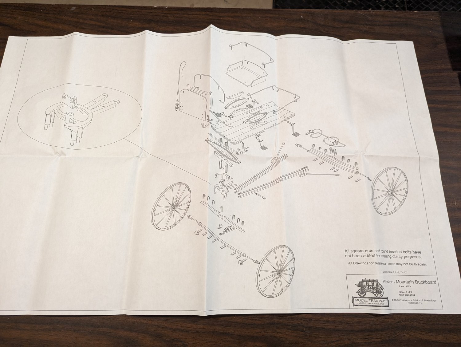
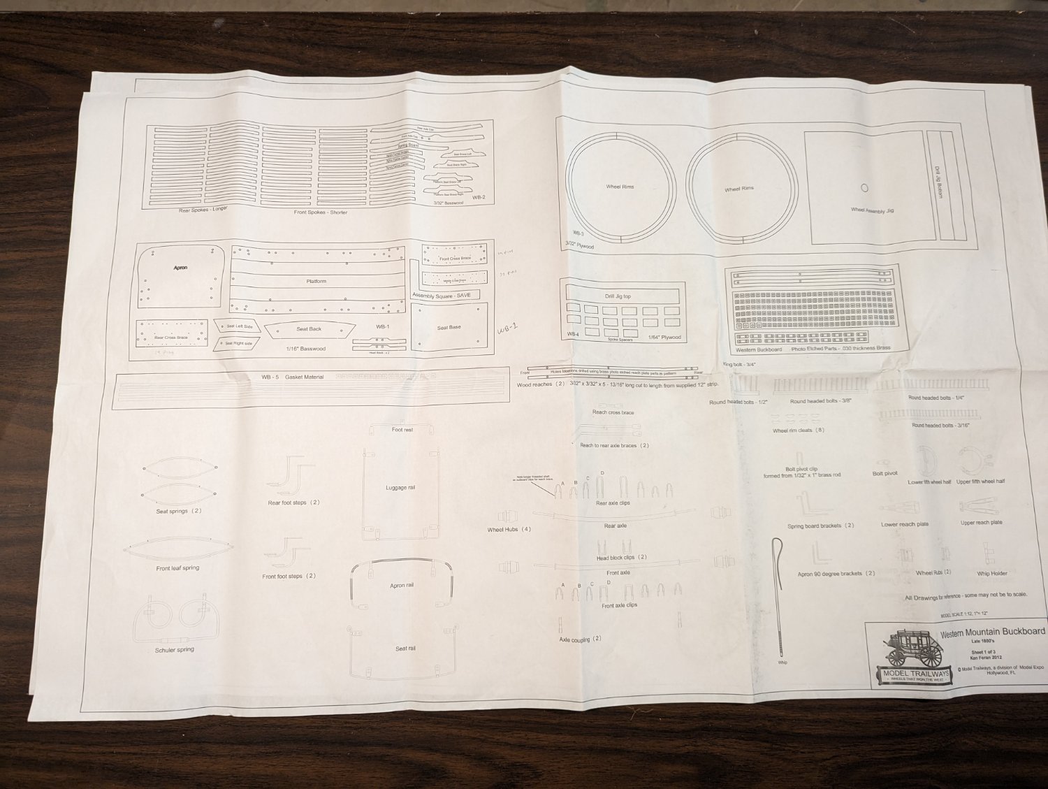
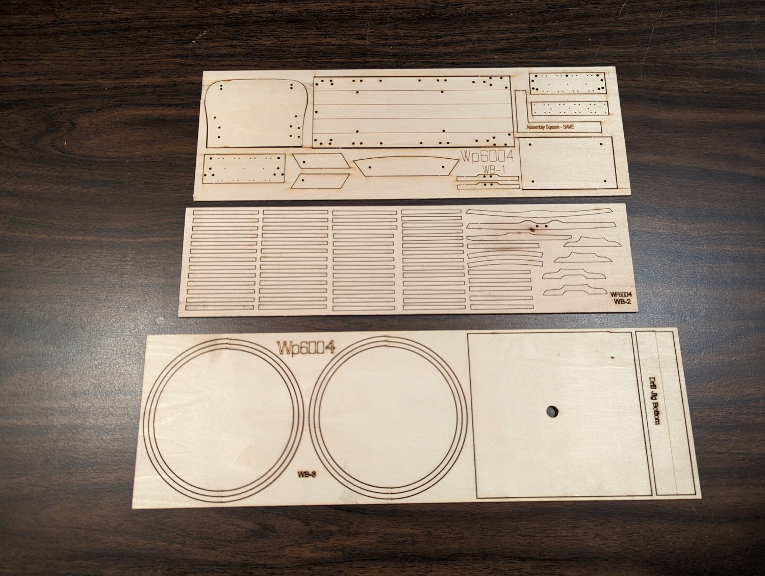
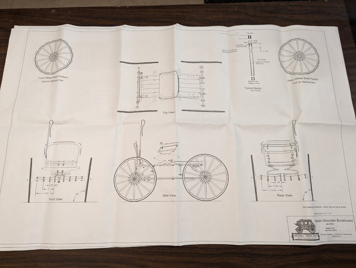
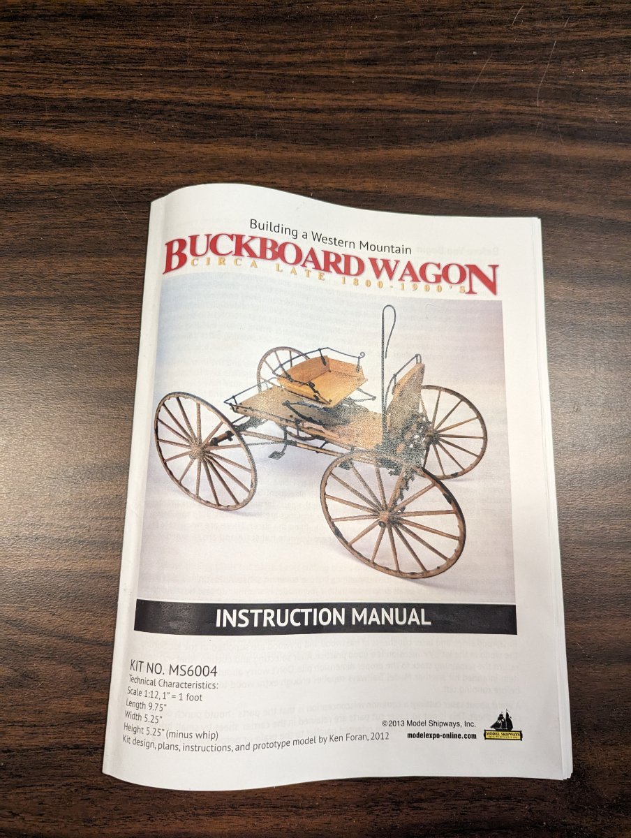
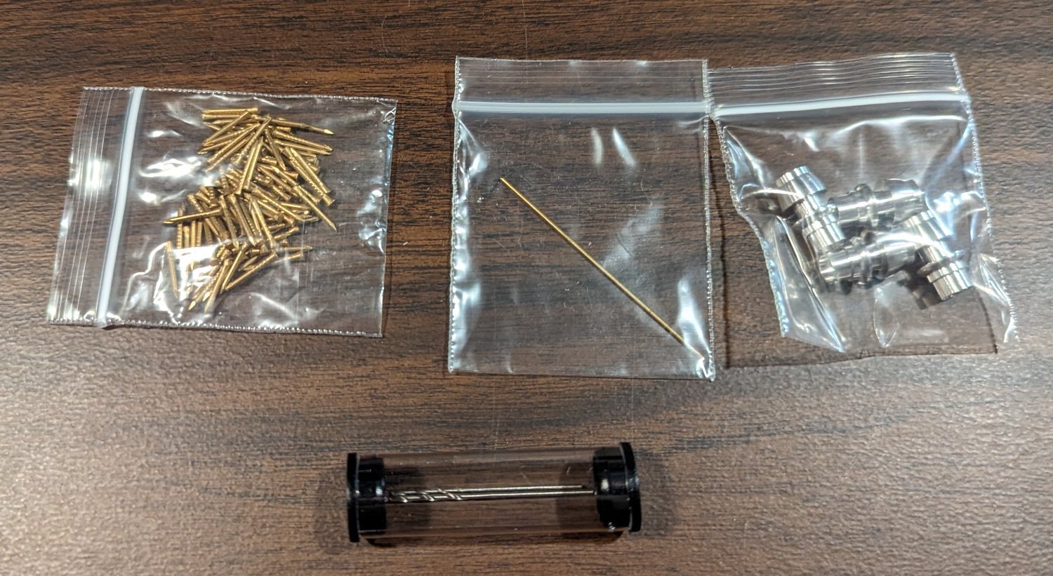
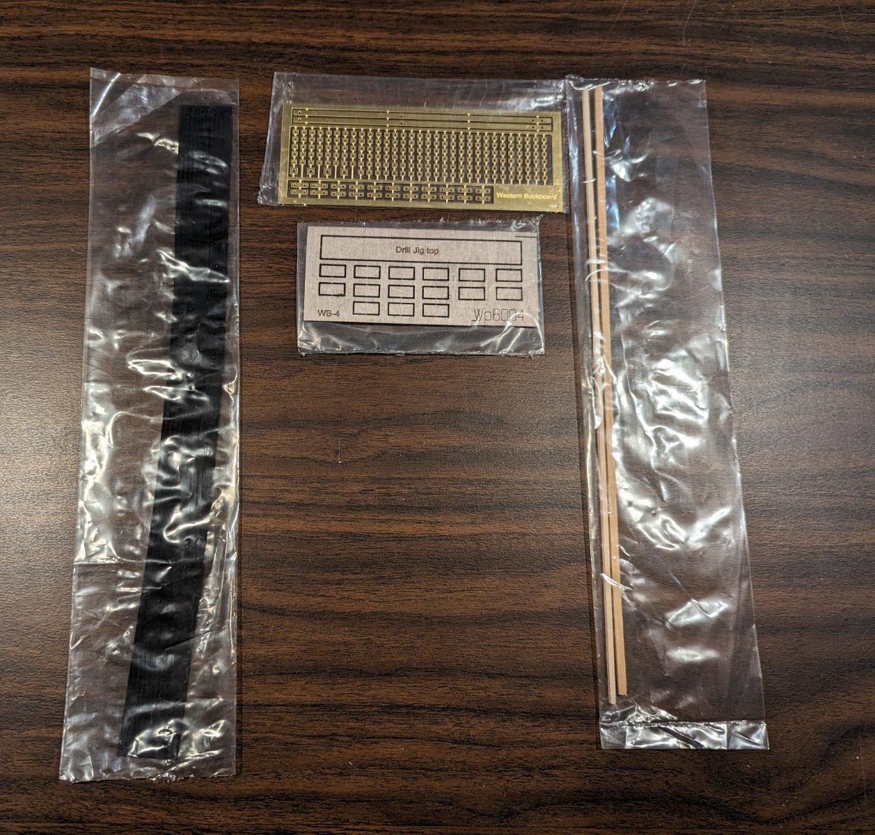
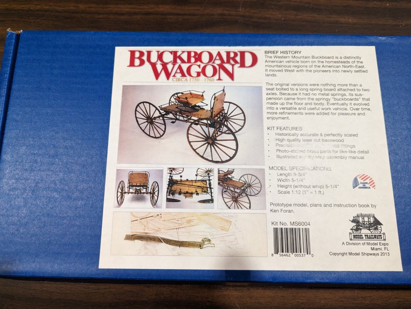
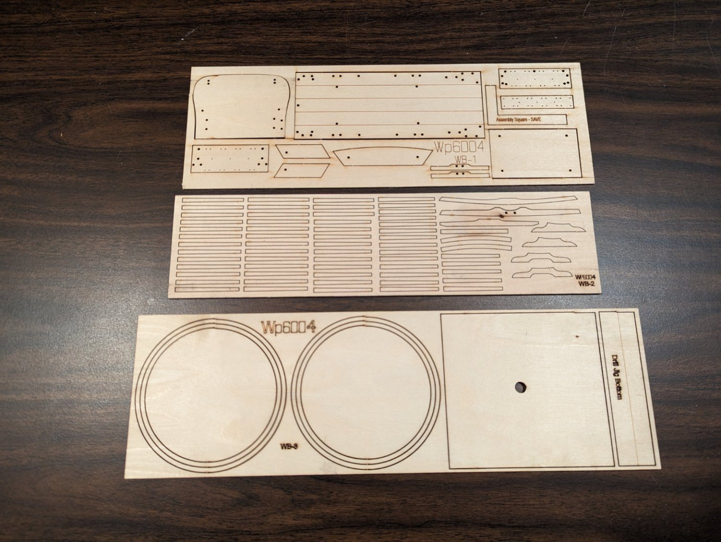
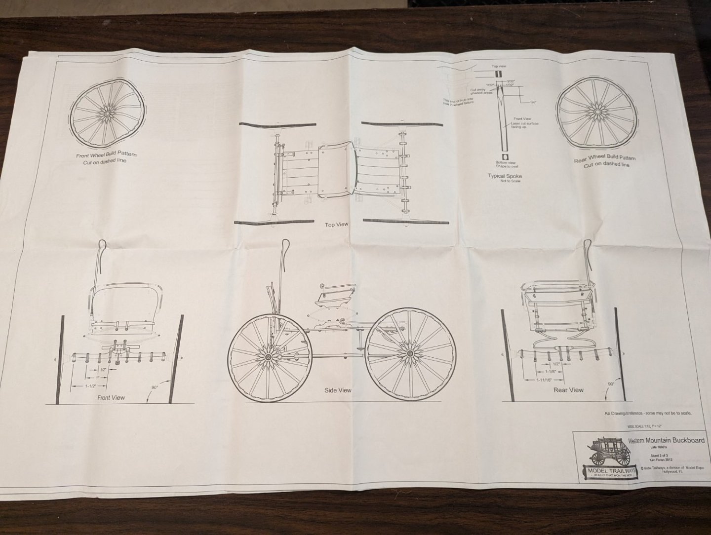
After working on several year long plus (to complete) models I wanted what I call a "quick win". Basically something that was quick and easy, but looked kind of neat. Saw the Model Shipways Buckboard wagon and the Hearse. Both caught my attention, but I settled on the Buckwagon... Maybe next time when I need a break from the marathons I will pick the Hearse. It looked like a "quick win" too. It will probably not be until end of the month (oct 2023) before I actually start on it, but I wanted to get the log started and the initial contents displayed. Also a word of warning... even though I call this a "quick win", in reality it will not be quick. I am not a true full time modeler... I only work models in my spare time... So this will not be one of those logs where you can follow along a I go. Log will be complete, but it will not necessarily be "quick". Once I complete the model this log will be able to be referenced by future builders of the Buckboard model. Hear is a quick view of the contents.. Seems like a nice instruction manual - about 50 pages with nice pictures. only three small wood sheets.. You can see why this falls into the "quick win" category. Three full page diagrams. The first one labeling many of the parts The 2nd and 3rd pages show various views and sections of the wagon Pins, wire, wheel hubs, and 2 drill bits. The drill bits are a nice touch. A ton of small soft BRITANNIA parts. UGH,,, some of these look so fragile, they look like they might break just looking at them... Will be (shall we say) "interesting" straightening them, cleaning them up, and painting them... Finally some Photo etched parts, dowel, and wood strip, and a cloth sets of strips... (shown in black on the left).


- 19 replies
-
- 15
-
-
Brian, It was frustrating at times and very monotonous putting in 80 planks, but looking at the final product, the bull rails really do look better mounted inward.
- 157 replies
-
- 2
-
-
- chaperon
- Model Shipways
- (and 1 more)
-
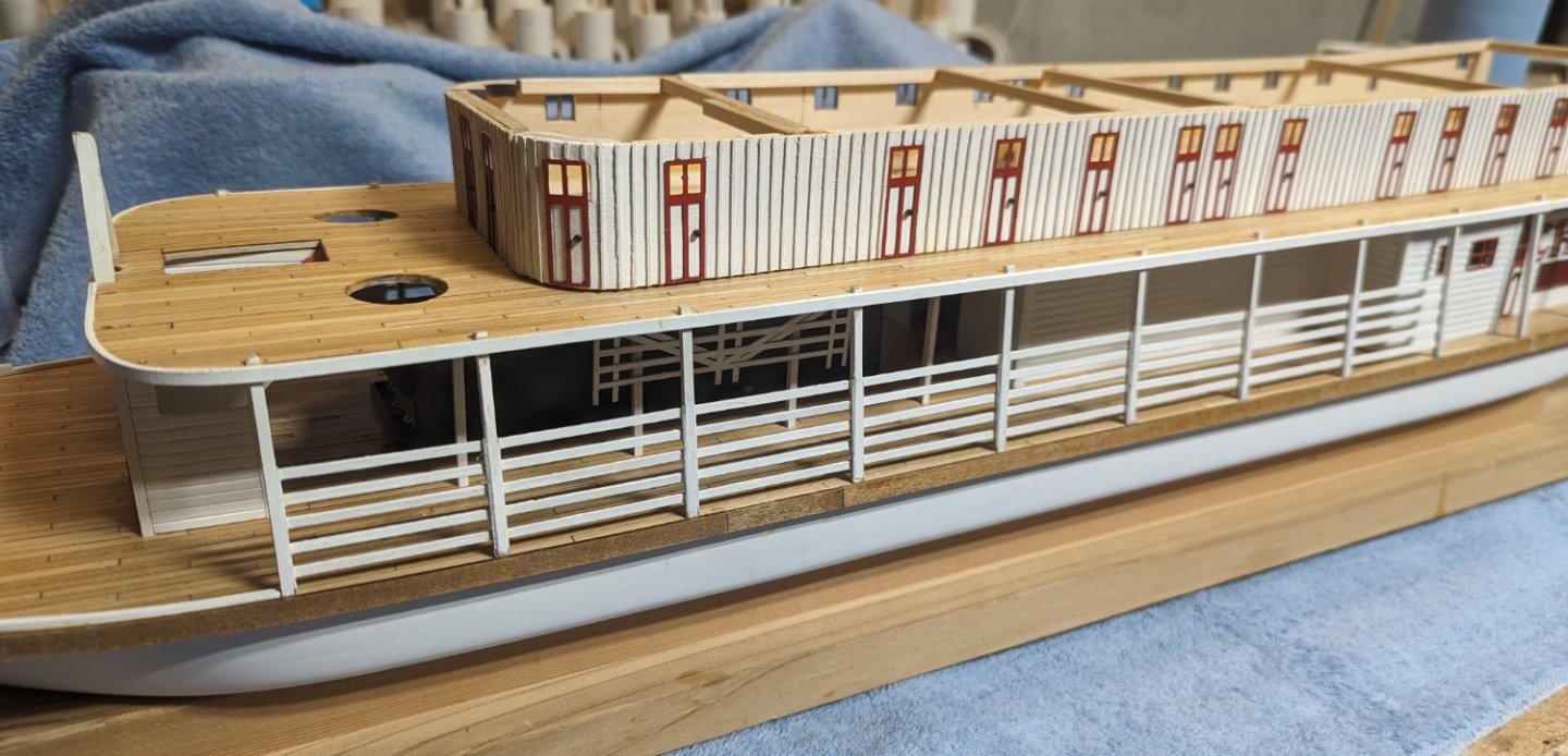
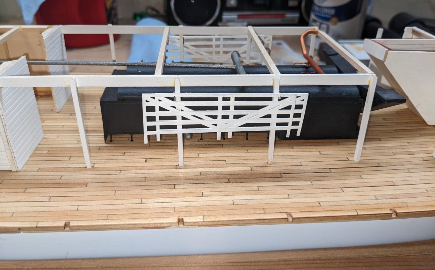
On to the outer bull rails.. These are 1/32" x 3/32" boards mounted on both the port and starboard side of the first nine stationaries. There are 80 of them - 40 on each side. The instructions call to mount the bull rails to parts 48 (bull rail brackets) mounted on on both sides of the stationaries on each side of the boat - "facing outward".. As mbp521 (Brian) mentioned earlier, this realistically is backwards. The bull rails are intended for the crew to be able to temporarily add or remove them to allow for easier loading or unloading cargo. Problem is with them facing outward there is no easy way for the crew (on board) to adjust them. Realistically the bull rails should be mounted facing inward. That way the crew can easily add or remove the rails as needed. Having said that, while more realistic, mounting the bull rails from the inside is easier said then done. There are five rows of bull rails and by the time you get to the 5th row there is very little room for big fingers to easily put in the rails. It can be done, but expect to have some level of frustration putting in these 80 bull rails - and of course knocking some out as you go 🙂 Below is my attempt at the bull rails

- 157 replies
-
- 4
-
-
-
- chaperon
- Model Shipways
- (and 1 more)
-
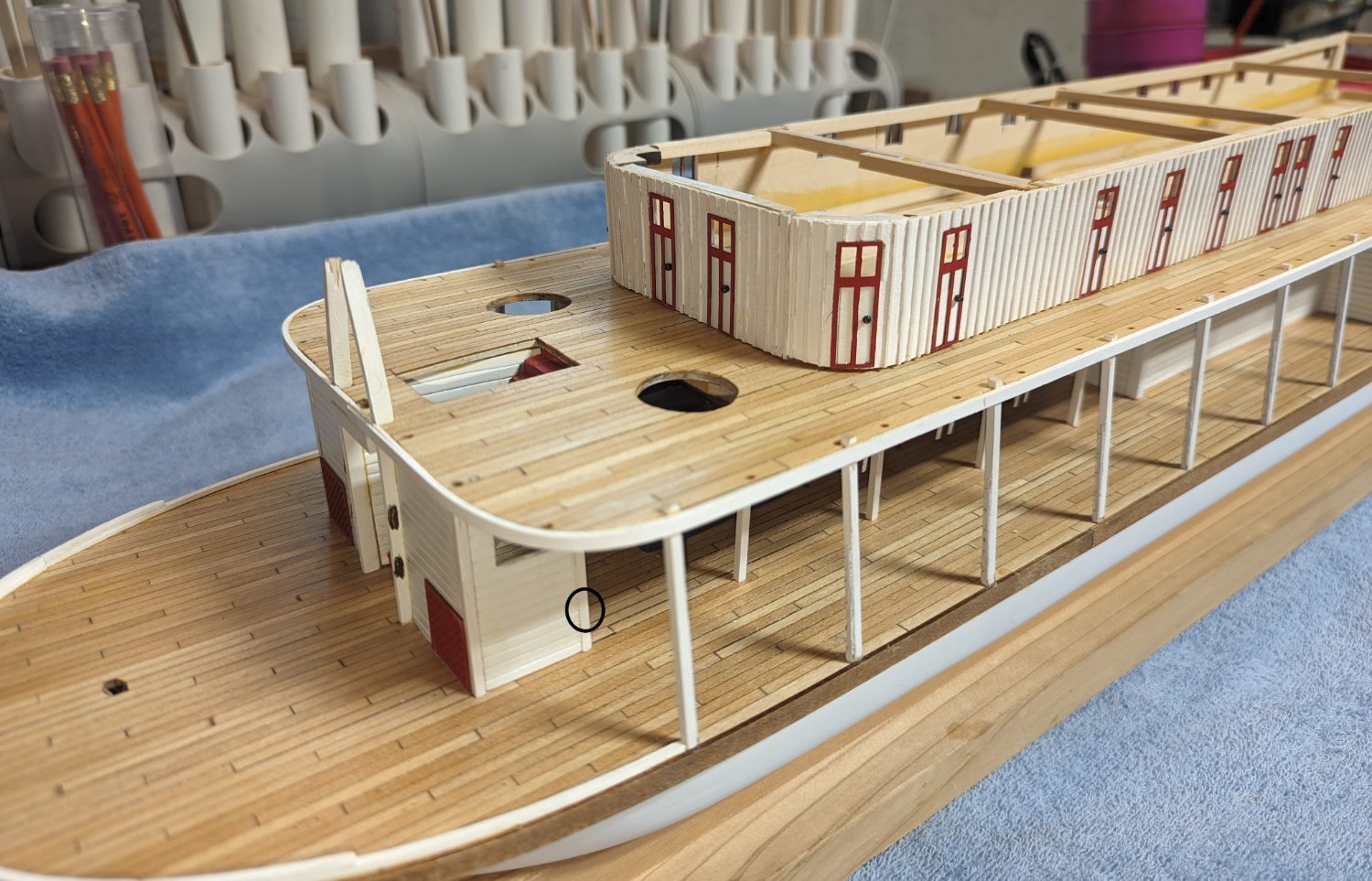
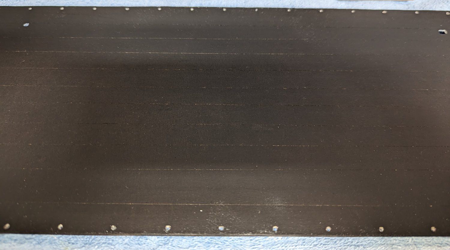
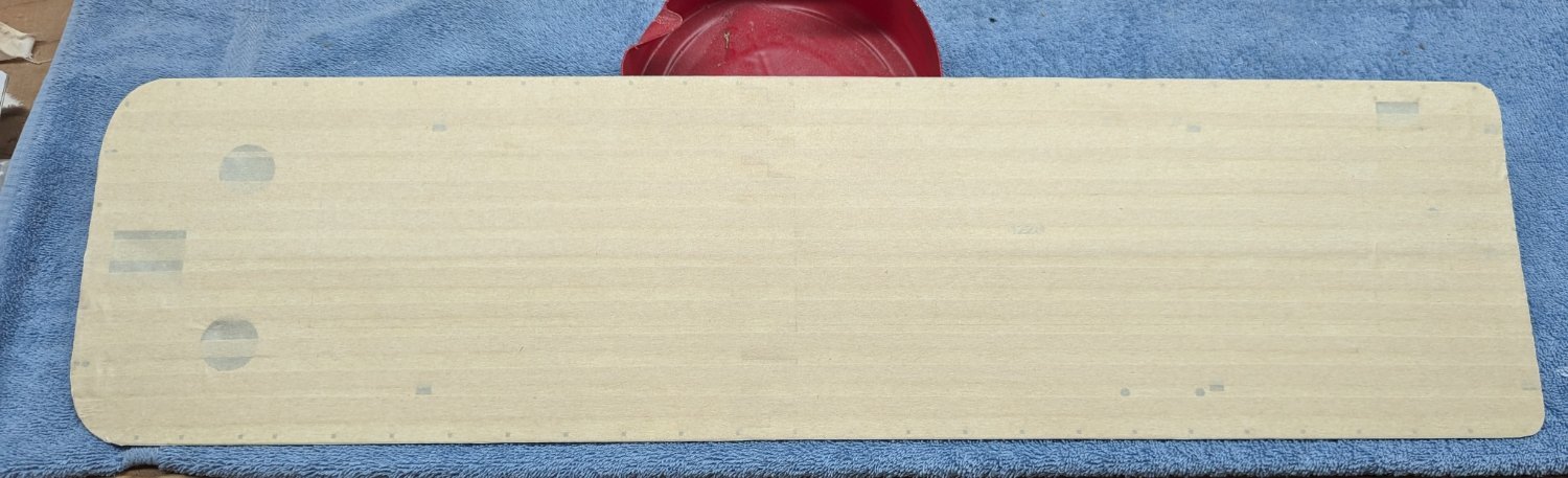
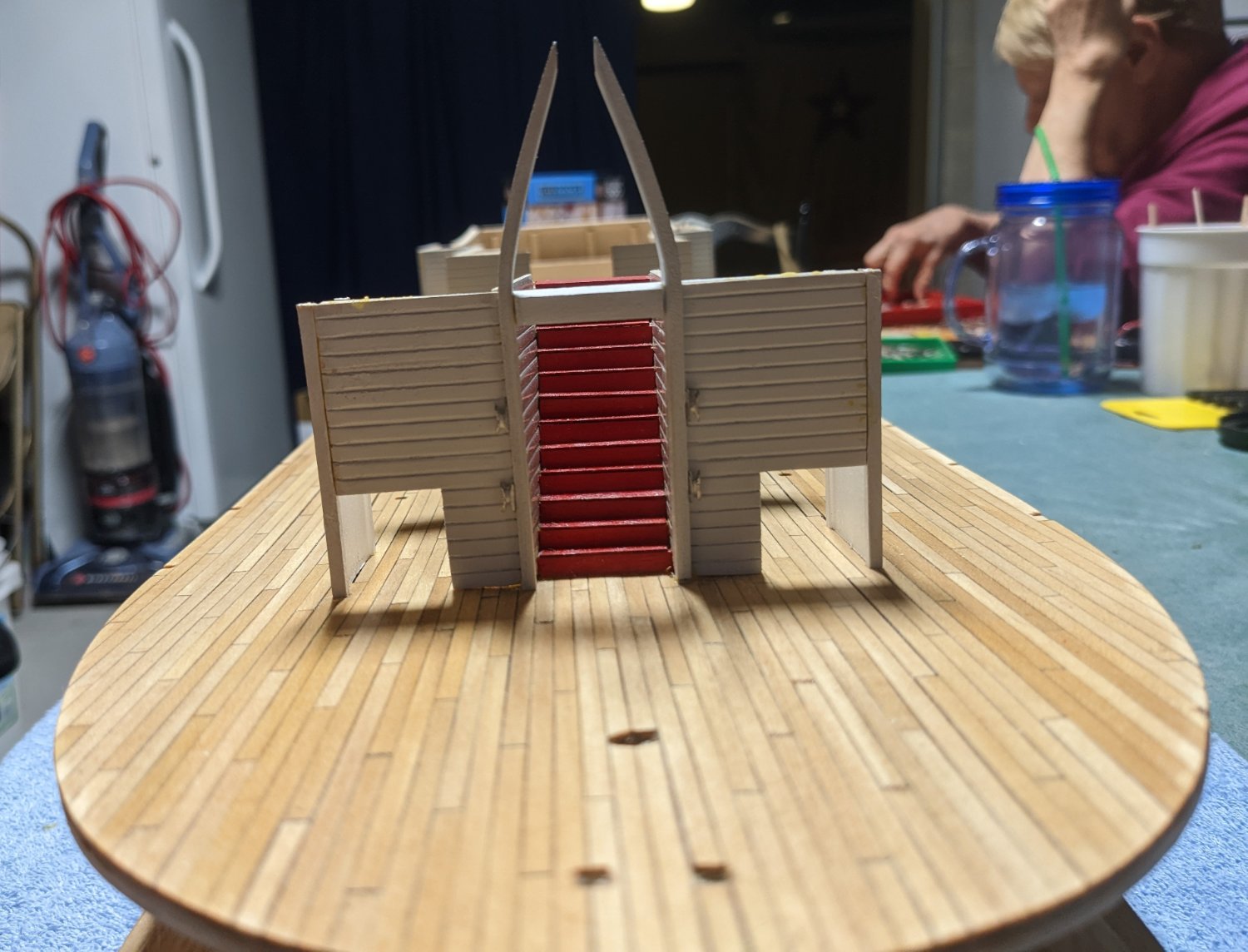
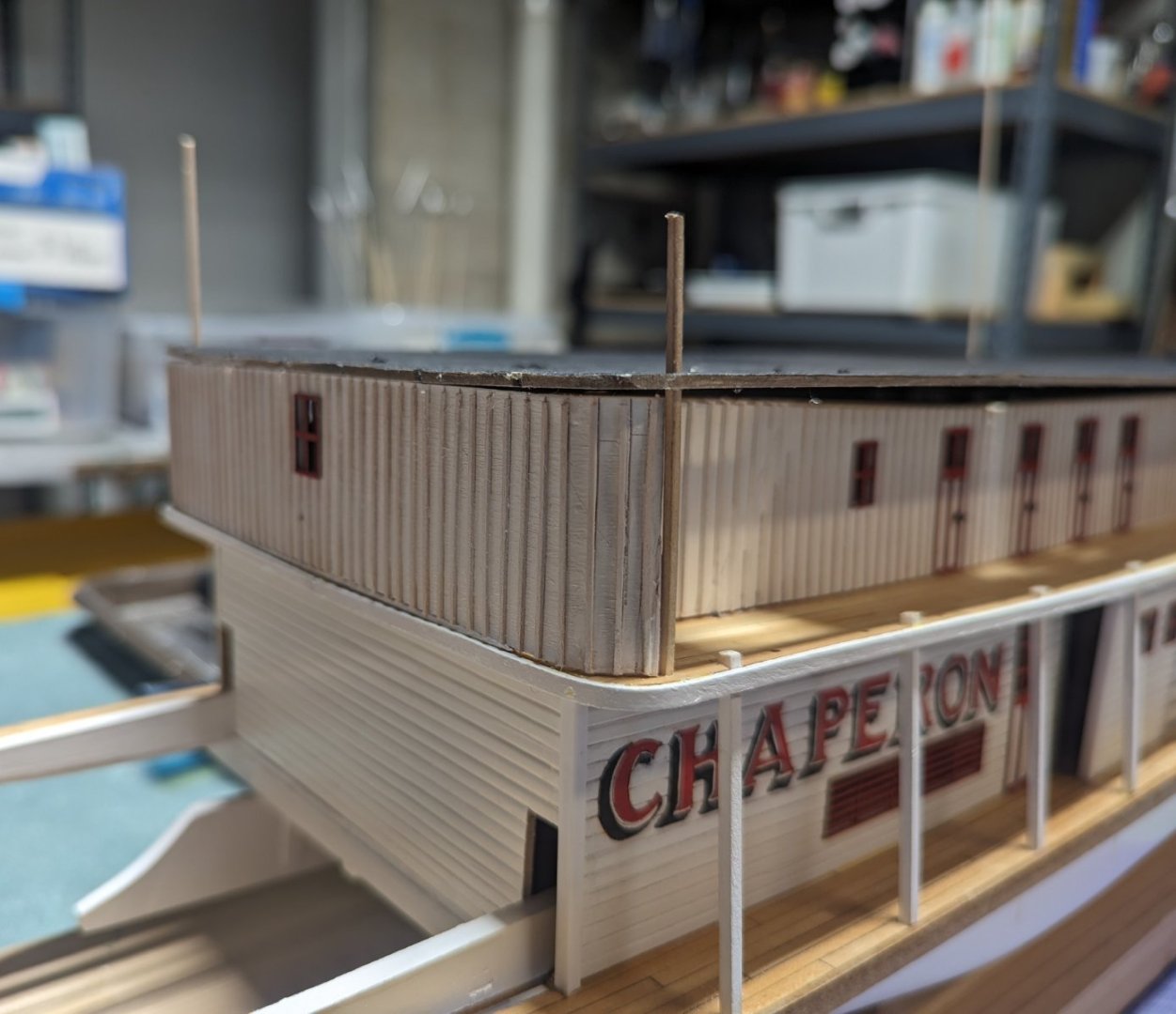
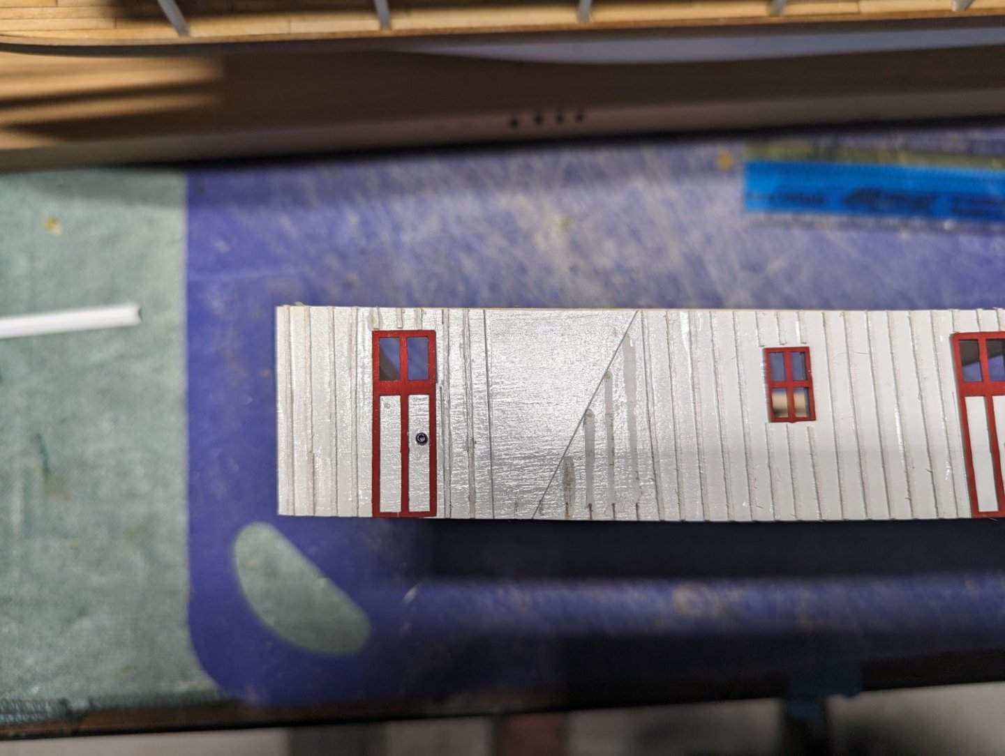
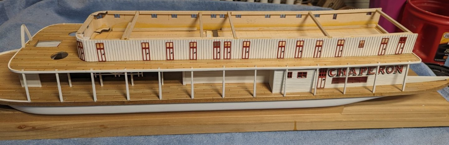
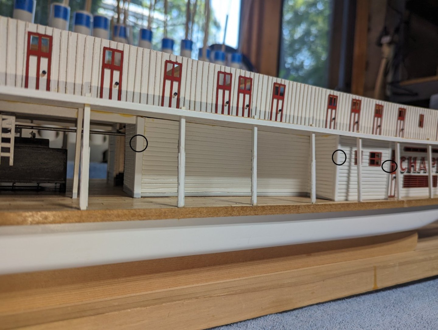
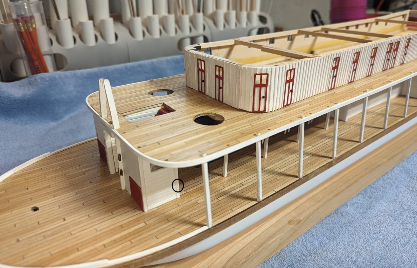
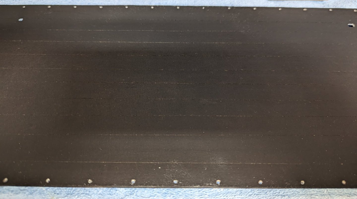
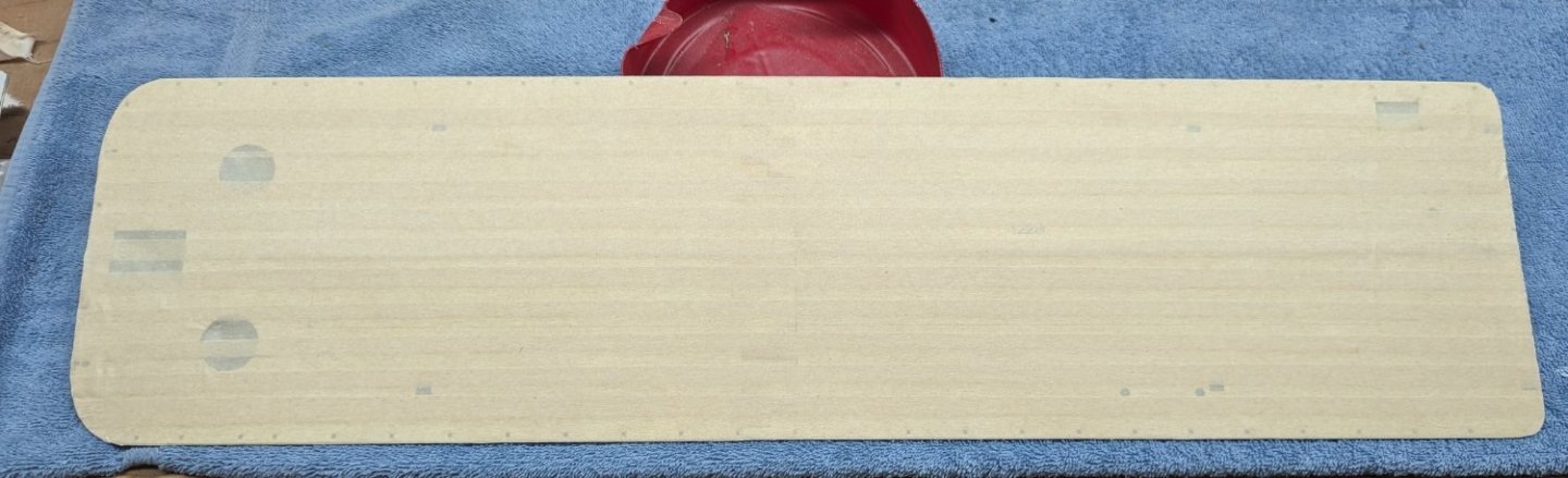
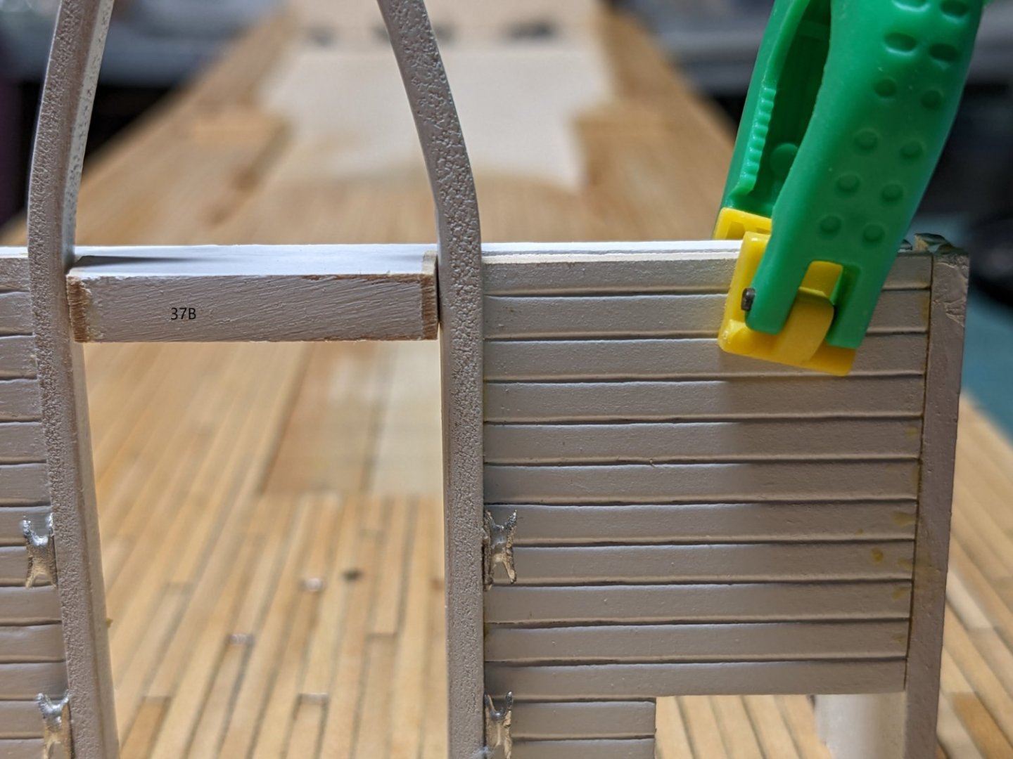
I appreciate the suggestions of "silk paper used to wrap gifts" and " regular tissue paper and ModgePodge", but I think at this time I am pretty well committed to masking tape. Below are the results after painting them a matte black. After overlapping the tape I sprayed from the opposite side of the wrapped tape to more show the seams... Not real sure I like the result as the seams show up as a lighter color than the black... Not a realistic look for tar seams, but I may leave it vs applying another coat of black and cover up the seams... Once piece of advice for novices' like my self... If you do cover the hurricane deck flooring with something, before you mount it on the main deck structure, be sure to verify all the holes in the deck have been opened up to later accept the pieces that will be going through them. Much easier now before you glue down the deck ceiling In preparation for laying the hurricane deck flooring I wanted to double check the alignment of all the posts and stairs that need to line up. In doing so I noticed the back stairs do not exactly line up with the wall etching. From the plans the stairs are supposed to line up against the wall - thus the etchings. When I first put on the vertical strips on the walls I assumed all was good and followed the lines. After seeing about a 1/2" gap between the stairs and wall I decided that needed to change. Others have mentioned this little fact, but I forgot. Since there is about a 1/2" gap that probably was wide enough for a person to slip by, so rather than extend the stair sides to meet the wall I decided to add the strips over the stairs etching in the wall. In the below picture, it shows the remains of the five partial strips that originally were on the wall. This was in preparation for adding new full strips. Below shows the new strips added. I probably should have closed up the etching before attaching the strips, and it would have been a lot easier, but closing that gap with a little extra paint can be done now too. Moral of this lesson is be sure to check the back stairs before you lay the hurricane deck flooring and make a decision as to what you want to do about the gap With all in place the boiler deck structures can now be attached to top of the main deck. Below are a few pictures of the final result One thing to note, on some of the raw corners I added some right angle styrene pieces to cover up the raw corner. I have some of them marked below with circles. Just noticed I have some extra glue showing,,,, need to break out the paint and fine brush 🙂


- 157 replies
-
- 4
-
-
- chaperon
- Model Shipways
- (and 1 more)
-
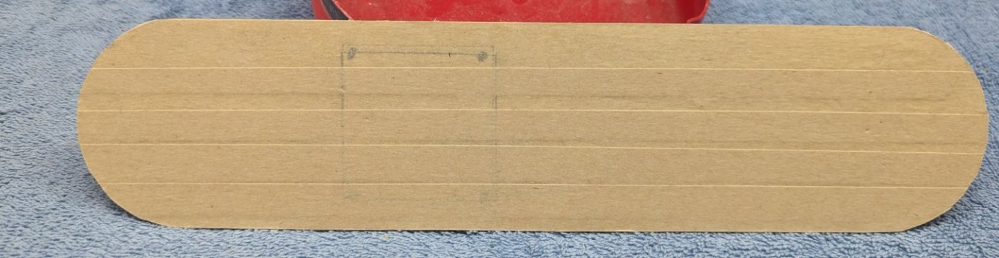
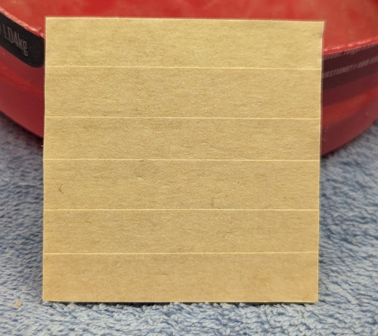
Earlier I was commenting on how I was in a quandary over the simulated tar paper for the Hurricane Deck, Skylight Roof, Texas Roof, and Pilot House Roof. Instructions call just to paint them all black, but others have commented that cutting silk span in strips and painting them black gave a realistic looks of tar paper. No way at my skill level was I going to be able to make strips of silk span look anything like tar paper. Beside, silk span seem to be really hard to find and very expensive. Cathead had suggested using overlapped masking tape strips and painting them black. That sounded like a neat idea and one that I could probably manage. Below is my attempt at applying the masking tape strips. If you look closely you will see the overlapped strips simulating the tar paper seams. Once they are painted black I think they will be a good simulation of tar paper strips Hurricane Deck Skylight Roof with Texas dry fitted. Texas Roof - You can see the outline where the Pilot house will be located Pilot House Roof Tomorrow I will get out the spray gun and a lot of black paint and spray away....

- 157 replies
-
- 2
-
-
- chaperon
- Model Shipways
- (and 1 more)
-
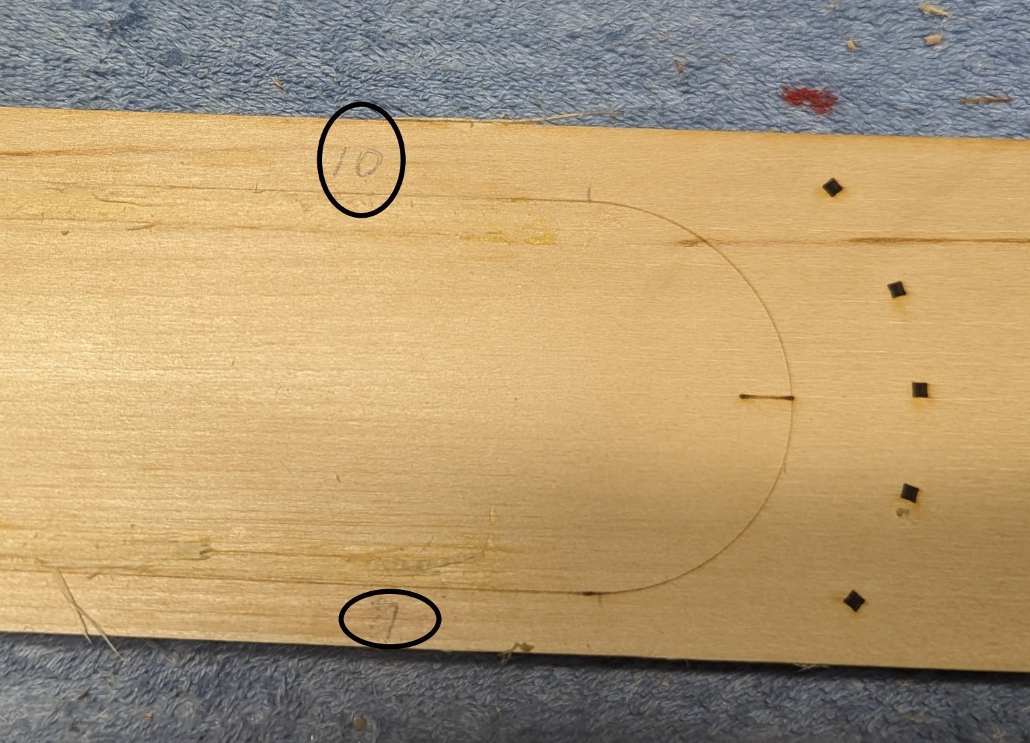
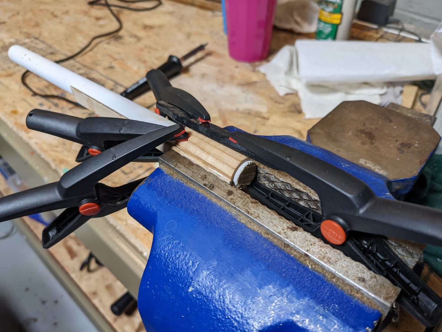
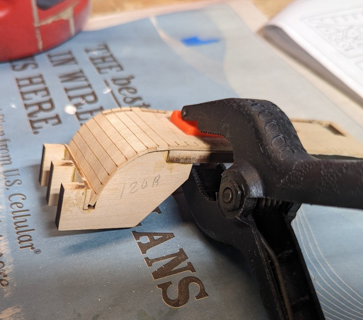
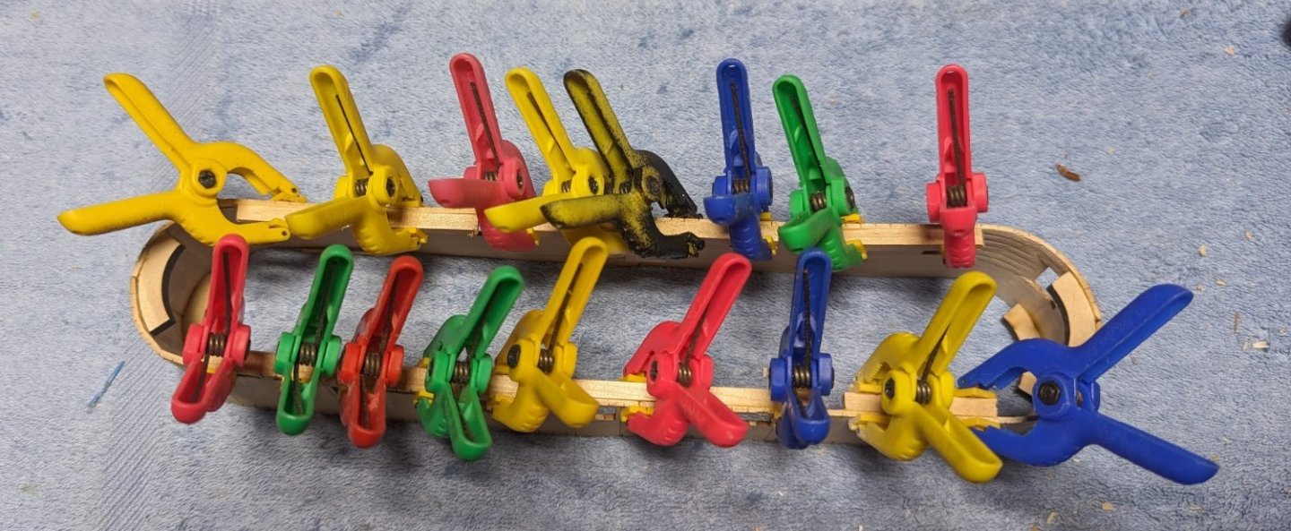
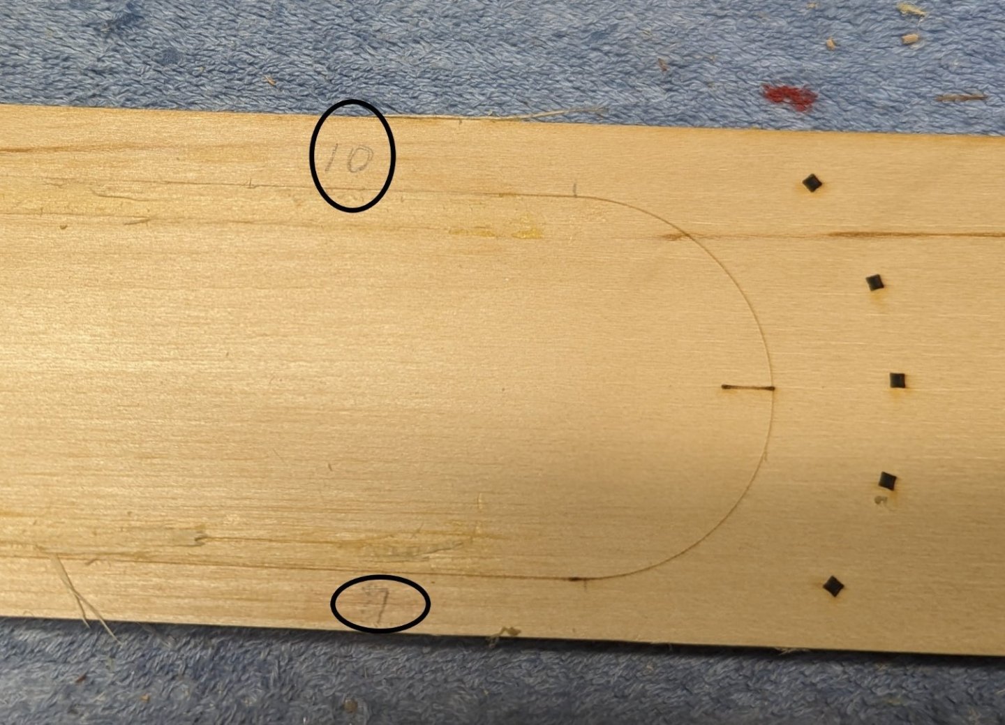
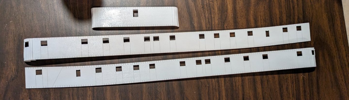
Started working on the stationaries... Stationary should extend above the boiler deck floor by 1/16"... In my case I felt it easier to make a little jig to insure they were all consistent. Below shows the jig. It really made it easier. Just placed the jig atop each stationary hole and inserted the stationary from the bottom until it hit the top if the jig. Also depicted in the below shots are the other jigs I used to insure equal spacing between the main and boiler deck. I would strongly suggest something like them. They take all the sport out of trying to insure a level deck. On to the Texas. Instructions here call to do something similar to what was done with the boiler deck walls. Make a jig and slightly score the etched marks to make bending them. It also says not to wet them due to the wall would end up cupped in the drying process. With my skill,,,,, no way was I going to be successful scoring those walls and bending them into the jig without breaking them. I more skilled modeler could do it, but not me. Instead I really needed to soak the walls to make those bends, but did not want the cupping effect. The cupping effect comes because the jig they suggest using only supports the bend in three places. A full jig that supported the entire bend would prevent the cupping effect. I found that a small juice can is very close to the proper bend that is required for these walls, and fully supports the entire wall over the bend. Thus I was able to soak the walls, bend them around the juice can, and let dry. The additional pieces of wood help support the wall over the bend. End result is very close to the actual bend required. At that point you can briefly soak the wall section and then use the suggested jig to get the required bend. Since the original bend was very close to the required size, the second bend in the jig has far less stress on the wood and thus not cupping as it dries. End result is a pretty good bend and way better than I could have done it by scoring the walls. Note I have also attached the 3/16x3/16 wood strips around the top of the Texas. I really liked them vs the suggested 1/16x1/16 strips. Much for forgiving and give a great gluing surface.. Since the Texas is a curved structure, one long strip will not do it. You have to break them into smaller pieces to more conform to the Texas curved top. I attached this picture just to show once again that "you can never have enough clamps" 🙂 Here is a fun fact that a more experienced modeler would know (obviously not me). Never assume the instructions or diagrams are correct. Always verify 🙂 Below is a picture the the Skylight roof showing where the Texas is to be located. Foolishly thinking the etching was correct I happily glued the 3/16 square strips on to it in preparation for installing the Texas. Note below the etching is not in the center of the Skylight roof. After the strips were dry and I dry fitted the Texas, the problem was very obvious. The etching is 10mm from the port side and 7mm from the starboard side. Thus, time for the alcohol and pry up the strips and re-center the Texas location. Maybe it is just my model, but please verify before you glue down the strips
- 157 replies
-
- 3
-
-
- chaperon
- Model Shipways
- (and 1 more)
-
MCB and Cathead, Thanks for the suggestions.... I appreciate the suggestions. I really did not want to just paint the deck black... I will give both of your methods a try on some scrap wood and see what I can do with it.
- 157 replies
-
- 2
-
-
- chaperon
- Model Shipways
- (and 1 more)
-
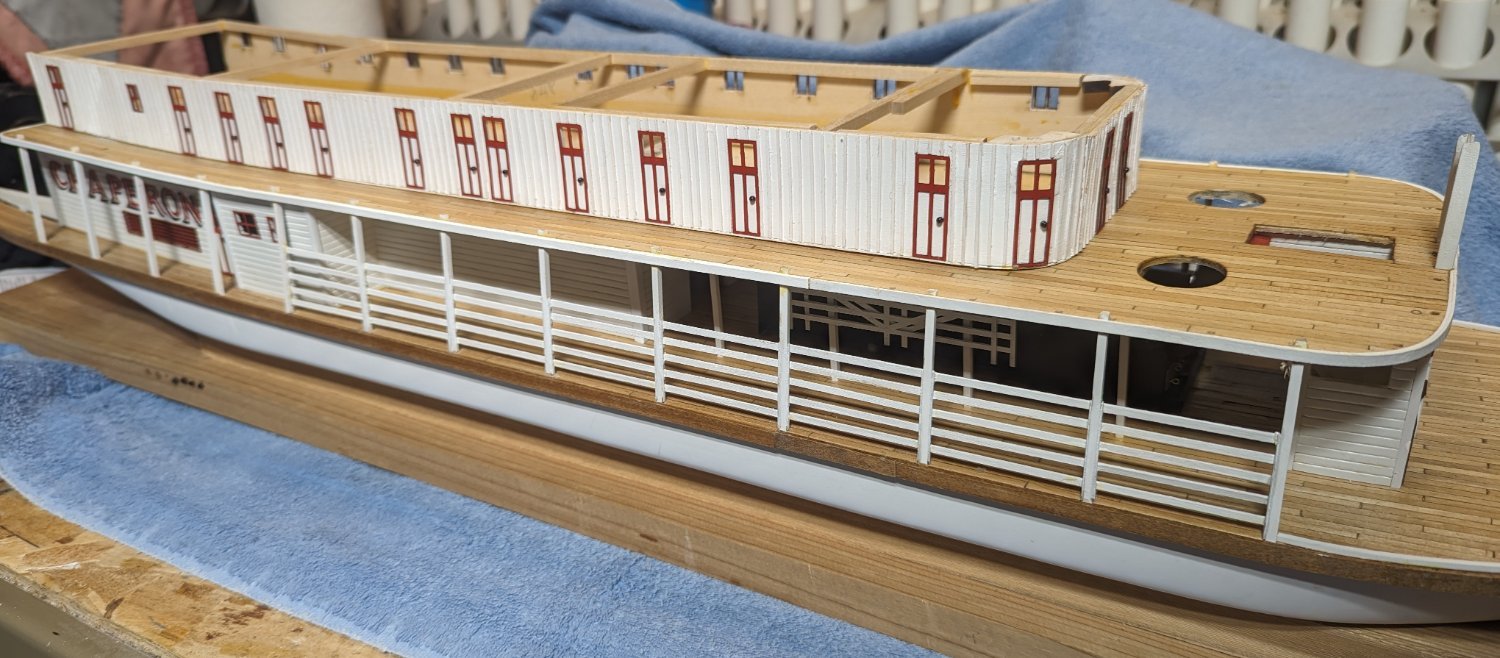
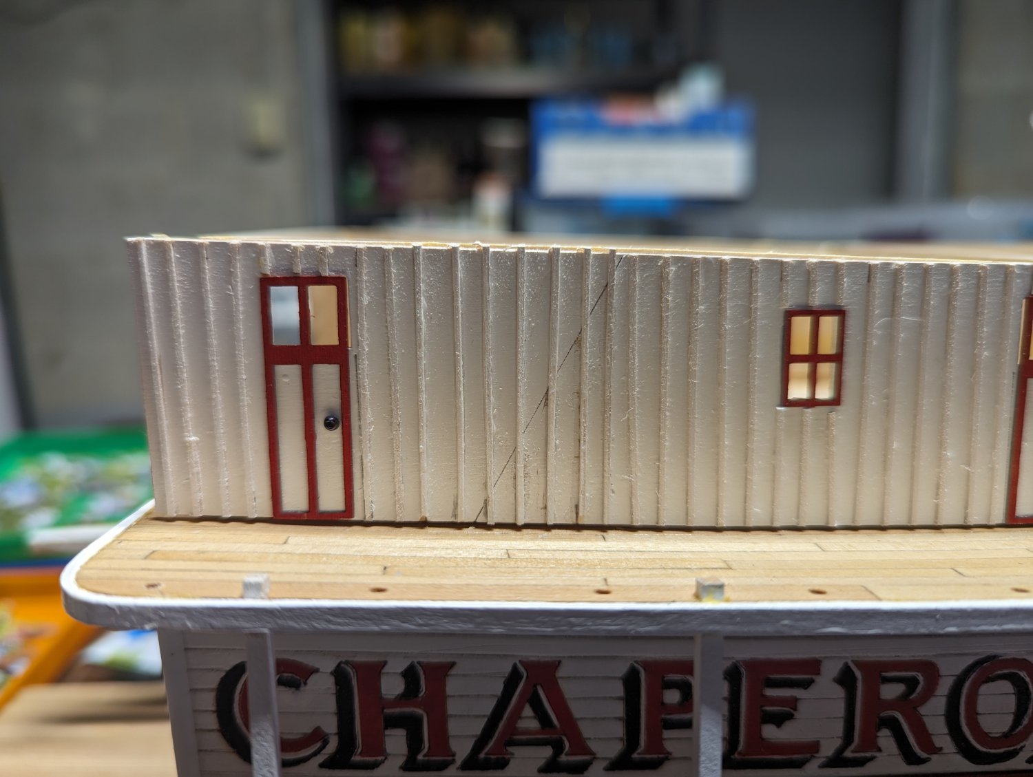
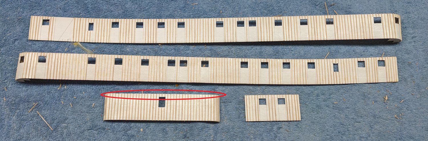
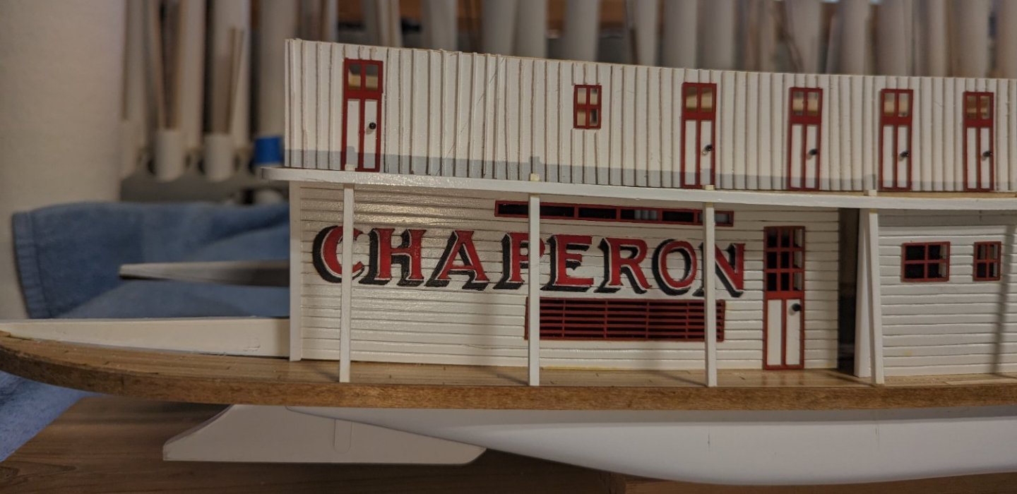
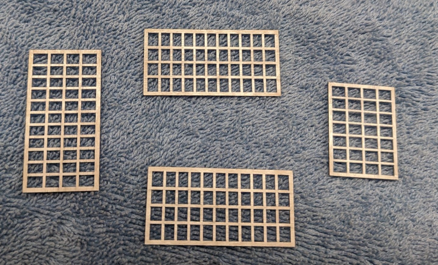
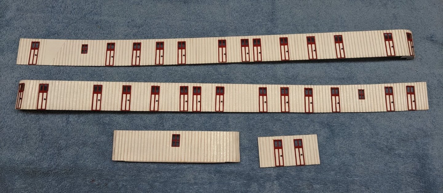
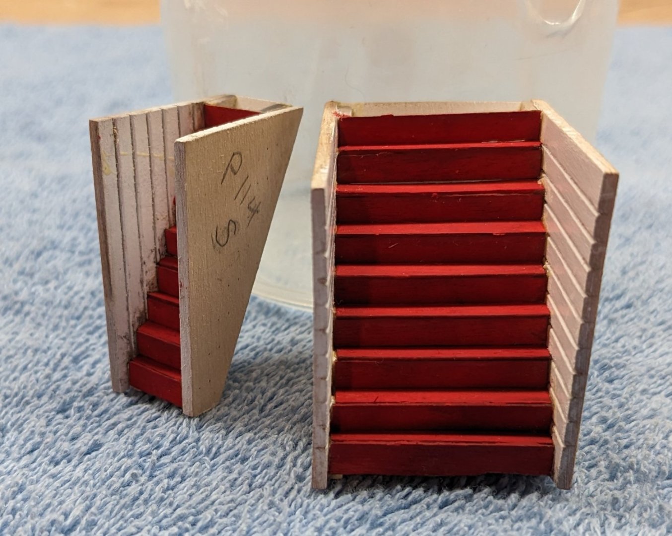
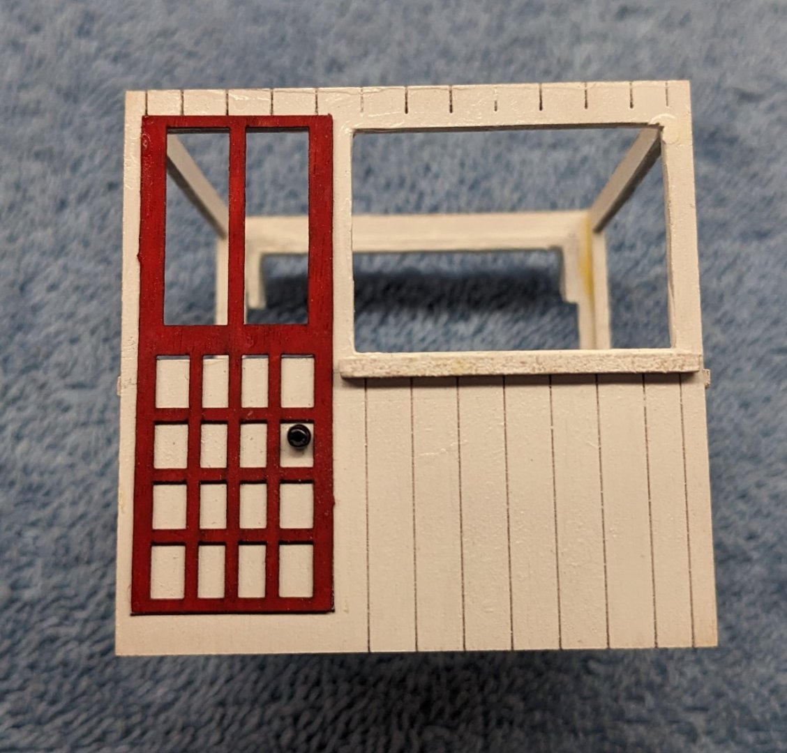
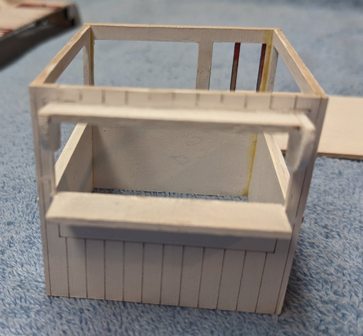
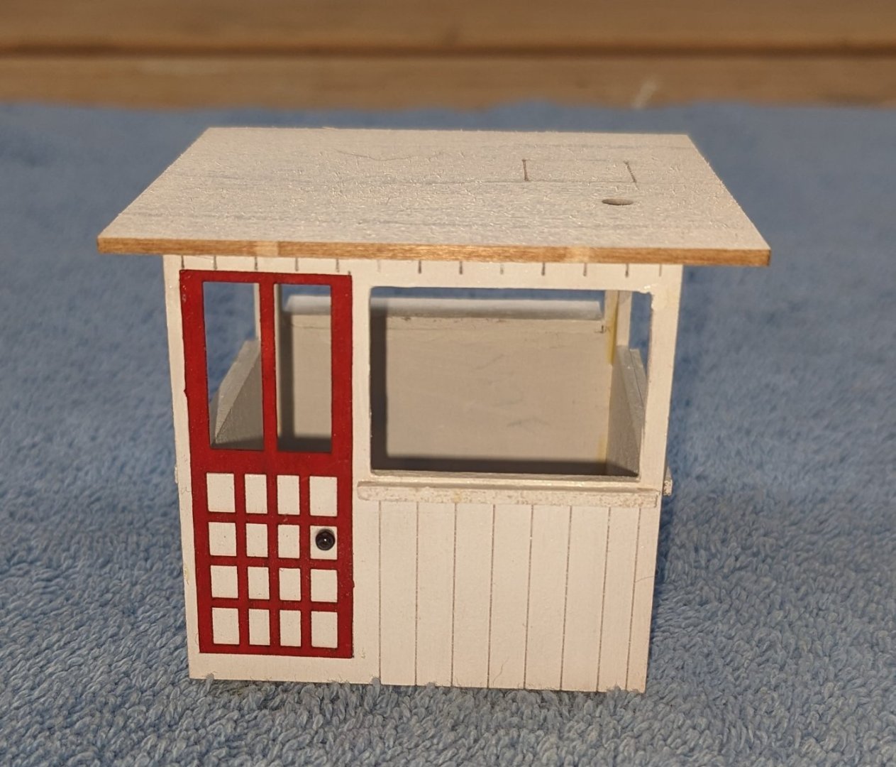
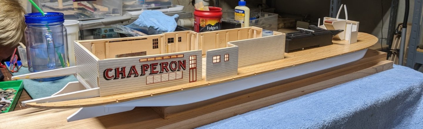
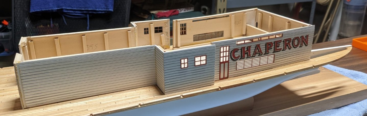
It has been some time (to say the least) since I last posted. Been out of town and away from the shipyard. I was able to take a few part with me to work on remotely. Was not able to take the hull due to it's size. Completed the boiler deck structure walls. Not a lot to say about this as it is pretty straight foreword, but very very repetitive. You will go crazy with all those 1/32" vertical pieces on the walls and then sanding them down to 1/64". After the vertical pieces were stalled, the walls were air brushed white. Afterward the red doors were attached with door knobs. Next took on the two boiler deck stairs. The forward stairs are is the larger on the and smaller steps goes on the aft starboard side. Only issue I had here was the fact that the step "runs" (on both sets of stairs) were a little short. Not sure it it was to do lack to skill on my part (in assembling the stairs) or were not sized right at the factory. Either way, they could not be used or there would have been a small gap in each step. There is plenty of 1/16" wood supplied with the kit and it was easy just to make new "run" steps and use those instead of the supplied ones. Still need some touchup paint, but they are more or less ready. Finally took on the Pilot House. This also is pretty foreword. I ordered a 1/48 scale pot belly stove and ships wheel to add a little more detail, but they have yet to arrive. As for the window, I know some have split the windows to simulate sliding windows. Not sure I have the skill to do that. I tried to simulate that by holding up one window over the other to see what that looked like but I just could not get it to look very good. I may try again when I get to the ship yard, but at this time I am leaning just to use the whole windows. As for the foreword window, that one will remain open. Still need some touch up paint when I get back. View of the foreword side Back side view View with Pilot House top on top. Not painted yet, just wanted to see what it would look like 🙂 On the topic, I am still on the fence as to the covering for the boiler deck, Skylight, Texas, and Pilot House. Kit calls just to paint it flat black to simulate tar paper. I know others have used silk span strips to better simulate tar paper, but I am having trouble locating some silk span. I found some at BlueJacket Ship Crafters, but it is $6.00 a sheet with $6.00 shipping. Not sure I want to go down that road, but I admit it would look much better than just flat black paint. Have to think on that some. And below are the windows mentioned above. At this time they just have one coat of while paint. Again an airbrush makes this task really easy to get a smooth finish
- 157 replies
-
- 3
-
-
- chaperon
- Model Shipways
- (and 1 more)
-
Olha, Oseberg has been on my list of future builds. The version of Oseberg from Pavel Nikitin looks really good. This may be my next build. Looking forward to following your build. Excellent unboxing video. Really first rate. john
-
As planking proceeds I guess it is time to air a little dirty laundry.... In regards to the boiler deck, the instructions call to glue the four pieces that make up the boiler deck into one solid piece and then attach it to the hull. That part is good... problem is since I was planning on planking the deck I felt it would be best to plank it after it was attached to the hull. My thinking at the time was that the extra glue and planking might make the deck stiffer and harder to attached to the hull. There are two problem with that logic... First issue is that since the vertical stationaries have not been attached yet, there is a lot of boiler decking in the front half of the boat without much support. And 1/16" planking being what it is,,,,, it could easily break when applying the planking if too much pressure is applied to the planks Ask me how I know this 🙂 You can see from the picture below where a little too much much pressure was applied.... calling for a repair job. What you can not see is all the tears.. The second issue with planking the deck after it is applied to the hull is also related to the lack of support on the deck. That being the glue as it dries tends to bend the decking (that is not supported) upward. I don't have a picture of it, but with the decking curved up on both sides, the hull looked like a bird flying. Thus repair job #2 comes into play. Basically I wetted the boards that needed to be bent back into shape and added some (shall we say) persuasion to hold them down. To insure they boards did not bend too far down there are some 3/16"x3/16" temporary support posts applied along the side of the hull. They are not glued and just held in place by the pressure of the "persuasion". Once the deck dry they will easily be removed. Disaster averted.. Had the same issue with a stern section but got creative with a clamp for the "persuasion". So,,,, if you plan to plank the deck I would suggest you plank the deck before it is attached to the hull. The planks will tend to bend the deck, but at least you will have a flat surface to add some weight to hold the decking down until the glue dries. And in reality the extra 1/32" planking will not add that much stiffness to the deck and will certainly be easier than trying to deal with split and bent decking if you plank after the deck is attached to the hull. Dumb you get early,,,, smart you get late 🙂 Tomorrow I will do the same process to the other side of the boiler deck
- 157 replies
-
- 5
-
-
- chaperon
- Model Shipways
- (and 1 more)
-
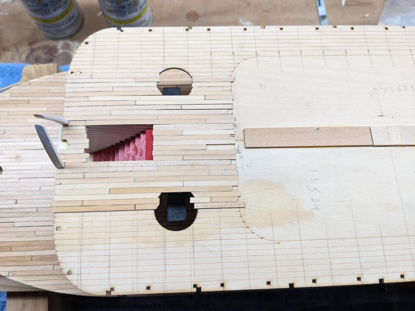
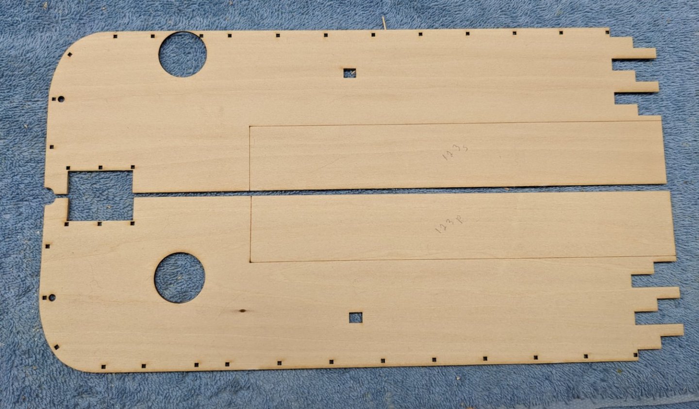
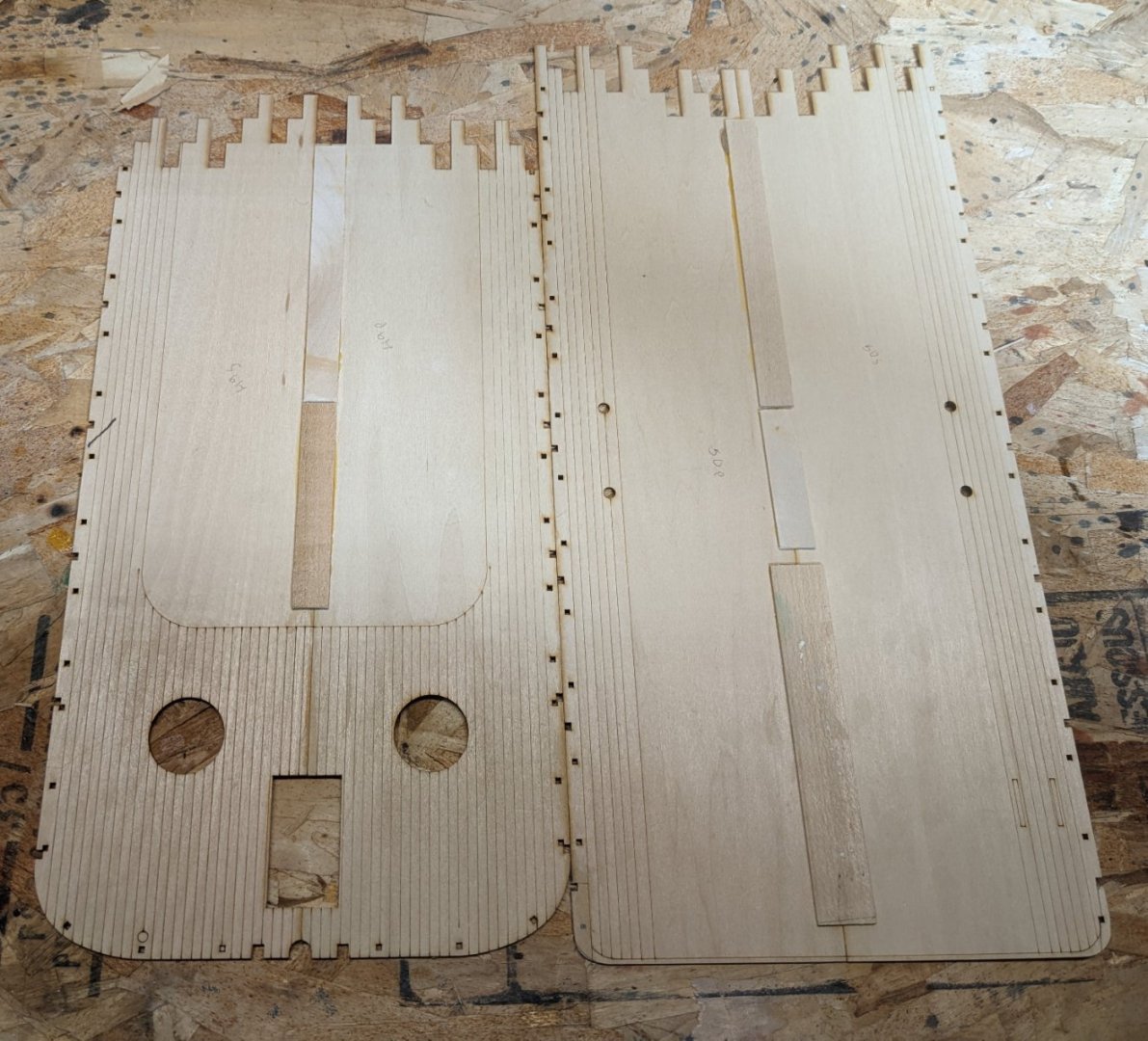
Finally started the planking of the boiler deck.... I hate deck planking,,,, I really like the look, but I hate doing it. Way to tedious and the process gets old pretty fast. As before I used the 1,3,5,2,4 planking pattern. Since deck planking is not fun enough I decided to take a break from planking and have even more fun with the 1/32" square battens on the boiler deck walls. Talk about getting old fast,,, wow.. Prior to planking I painted the walls just to get the first few coats on them. I then added the 1/32" square battens. After that I will just air brush to put on the final coats. Probably could have just waiting until all battens were installed, but I figured it would be easier this way. Once all is painted I will add the windows/doors that were painted earlier. Instructions call to sand the 1/32" battens down to 1/64" to look more realistic. When I first read that I thought that was some sort of designer joke, as no way (at my skill level) would I be able to do that. But when you think about it, after the battens are glued into place, a sanding stick easily trims them down to look more realistic. Note in the stern wall section the battens (in red) do not go all the way to the top. This is to allow for the deck trim (added later) to not interfere with the battens. In order to get a better connection between the side and bow sections, I added a piece of scrap wood. I plan to connect the side and bow sections together and then put the structure onto the boat. If I glued the pieces to the hull separately, I have a feeling that joint would not go together too well. Looking ahead I noticed a little issue,,,, with next boiler deck ceiling (Hurricane deck floor). What is wrong with this picture? Seems to be an issue with the smoke stack hole on part 123S. 🙂 Not a big deal, it will be awhile before I get to that point. I opened a ticket with Model Shipways and I am sure a new part will be here well before I need it.

- 157 replies
-
- 4
-
-
- chaperon
- Model Shipways
- (and 1 more)
-
Brian, Thanks for that heads up.... You are correct.... if the bull rails were installed as indicated in the instructions it would be rather difficult for workers to take them up and down from onboard the ship. When I get to that stage I will mount them as you suggest...
- 157 replies
-
- 2
-
-
- chaperon
- Model Shipways
- (and 1 more)
-
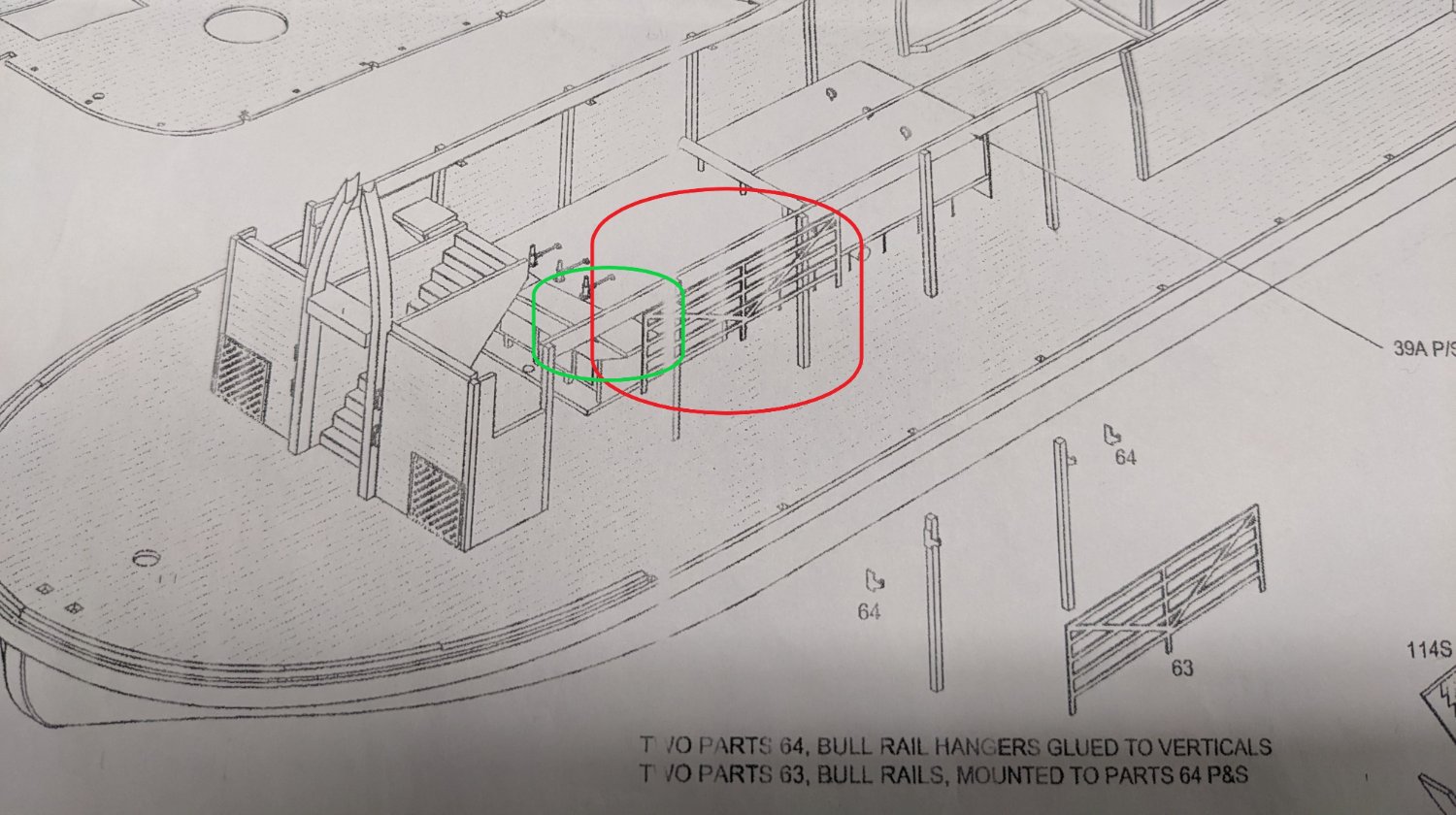
Brian and Cathead, I mis-quoted earlier when I said the instructions called for mounting the bull rails on the 1st two posts. In reality the instructions just said to "mount the bull rails" - do not really say where to mount them. I got the idea of the 1st two posts from looking at diagram #2 . Actually diagram #2 is old and really needs to be updated. Diagram #2 not only shows the bull rails mounted incorrectly(red highlight), it also shows part 39A extending forward (green highlight). Looking back at earlier build logs it was discovered (and reported to Model Expo) that 39A had to be trimmed back due to interference with the smoke stack covers. Model Expo took note of the exception and updated the instructions with the following comments. Also note that parts 39A P/S will have to be cut away at the forward ends where they are in the way of the smoke stacks. They did not update the fact that that the smoke stack covers also interfered with the bull rails causing them to be mounted farther back than on the diagram. Anyway, not a big deal, but for newbie's like myself that foolishly follow the instructions/diagrams, I thought I would point this out. Bull rails do not get mounted on the 1st two posts due to interference with the smoke stack covers

- 157 replies
-
- 2
-
-
- chaperon
- Model Shipways
- (and 1 more)
-
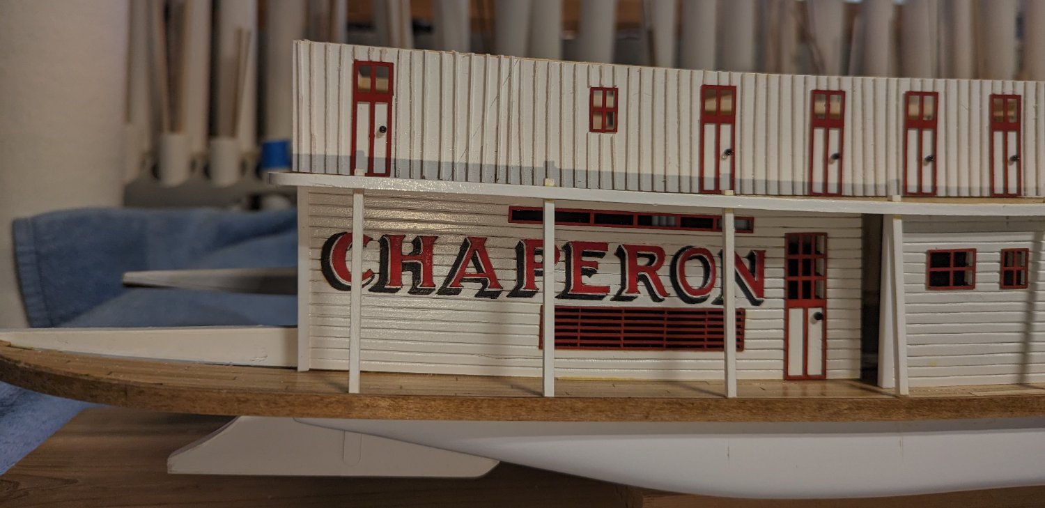
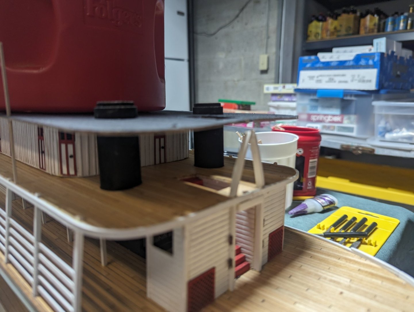
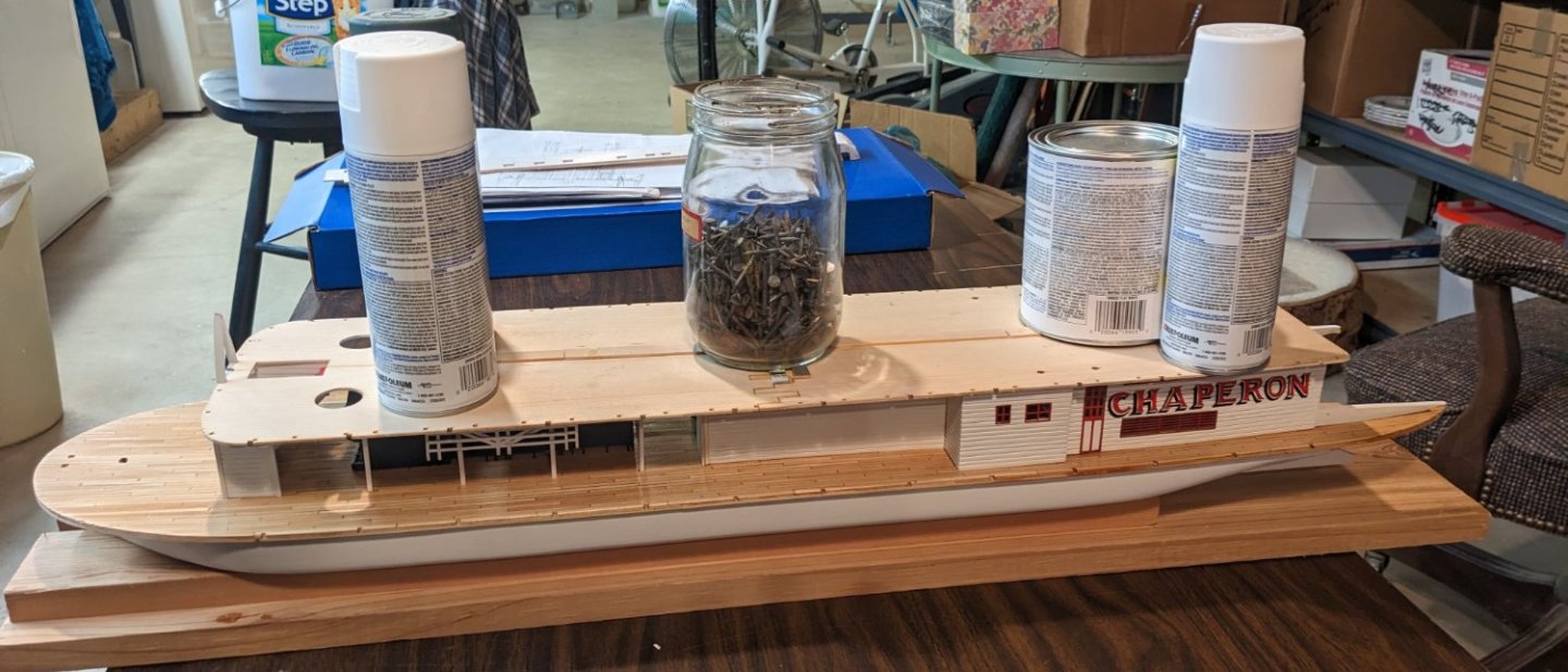
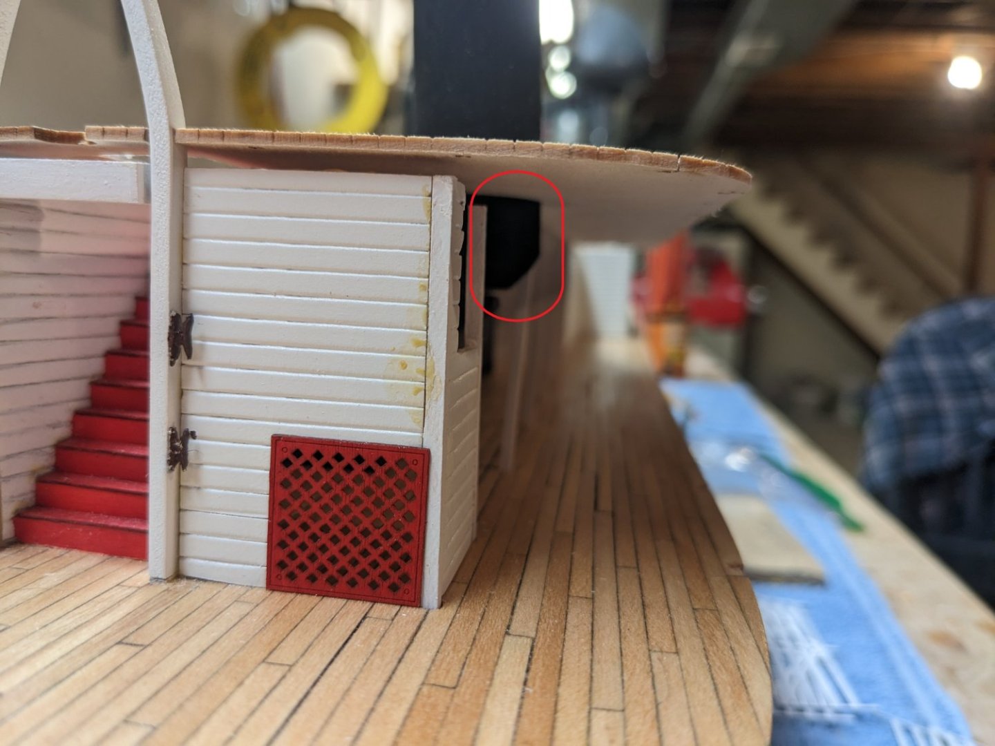
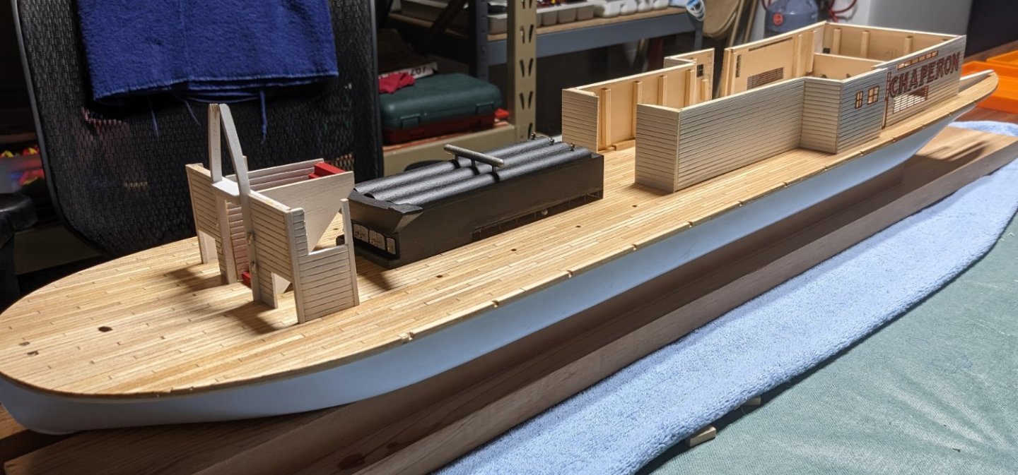
Been awhile since I last posted,,,, Holidays and other stuff seems to have diverted me from building... Anyway I have not been completely idle. Started painting the boiler deck walls with air brush. There is defiantly a learning curve with one, but learning is pretty quick. All the window/doors have been painted, but not yet attached. Air Brush is defiantly the only way to paint those. Painting the window/doors with a rattle can or brush would be a challenge. After bending the steam valve pipe air brush comes in handy painting it copper. I know the steam pipe does not go directly into the smoke stacks, but bending was a challenge to me and once I got to touch the support, I did not want to risk messing it up. There is a slight indent opposite the steam pipe to accommodate the smoke stack so I guess we can assume the steam pipe goes through the support and into the stack 🙂 Instructions call to mount the bull rails on the first two support posts in the boiler room. Problem is, even though the boiler support structure is inside the support structure, the smoke stack protrudes outside the structure. So bull rails need to be attached to the 2nd/3rd supports posts. I do not think is "builder error" and instead a design flaw, but knowing my skill, builder error may have come into play. Below you can see the smoke stack bulging out just after the first support beam, Also still need to get out the alcohol and do a little glue cleanup. Earlier I glued the two front sections and two back sections of the boiler deck. I was planning on just gluing the two sections together when I attached them to the hull. But after thinking about it, why not just have the one deck piece and glue the entire deck onto the hull. I glued a few extra strips of wood over the joints to add a little more strength. That may have been overkill. And finally boiler deck was glued onto the hull with some additional (shall we say) "persuasion" to have it conform to the hull curve.
- 157 replies
-
- 5
-
-
- chaperon
- Model Shipways
- (and 1 more)
-
Brian, As I indicated in my post..... I broke a lot of practice wood before I figured out bending around a solid pipe would help... "Dumb you get early smart you get late"
- 157 replies
-
- 1
-
-
- chaperon
- Model Shipways
- (and 1 more)
-
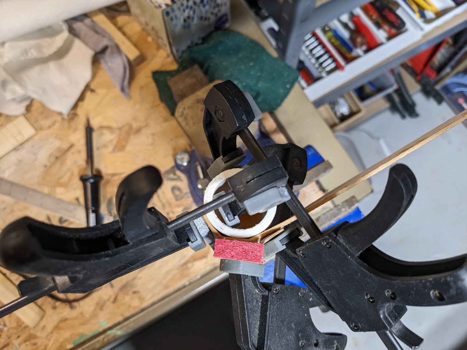
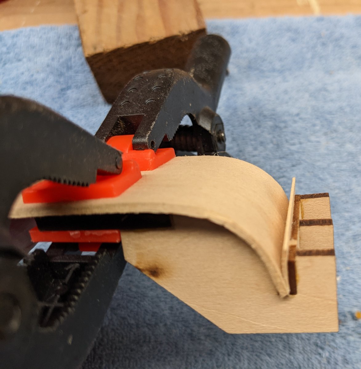
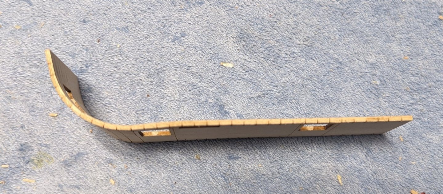
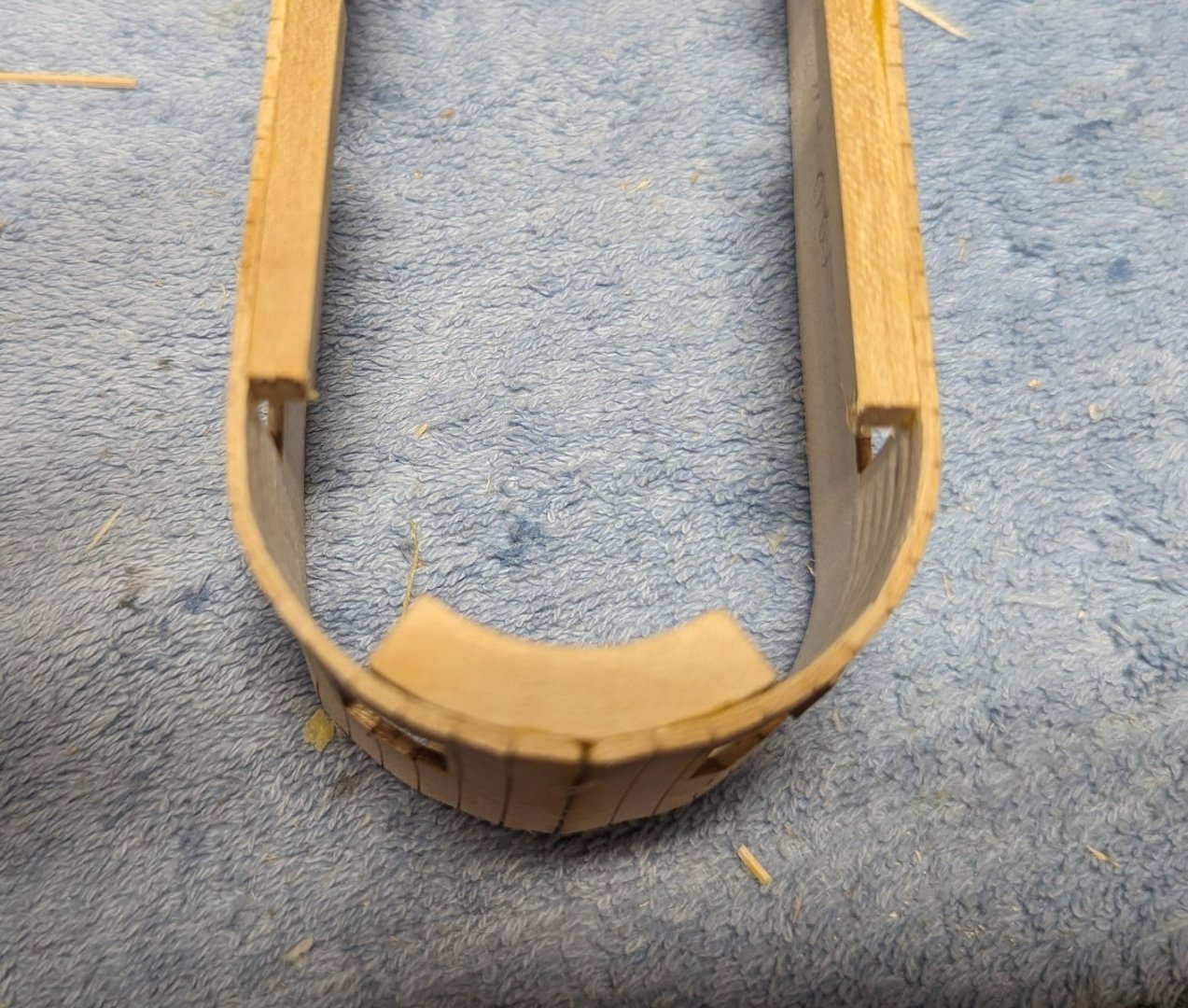
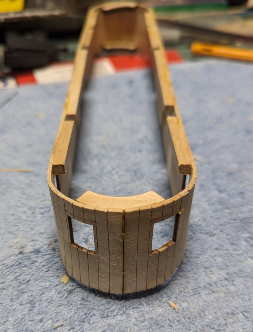
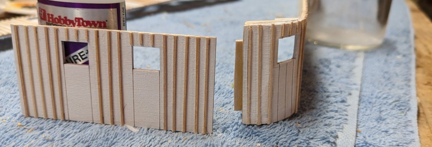
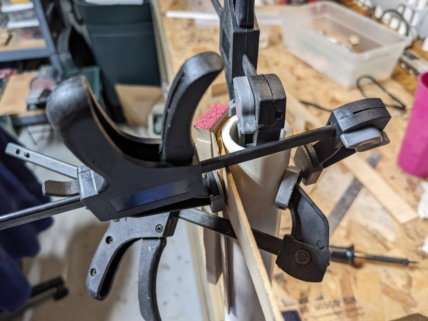
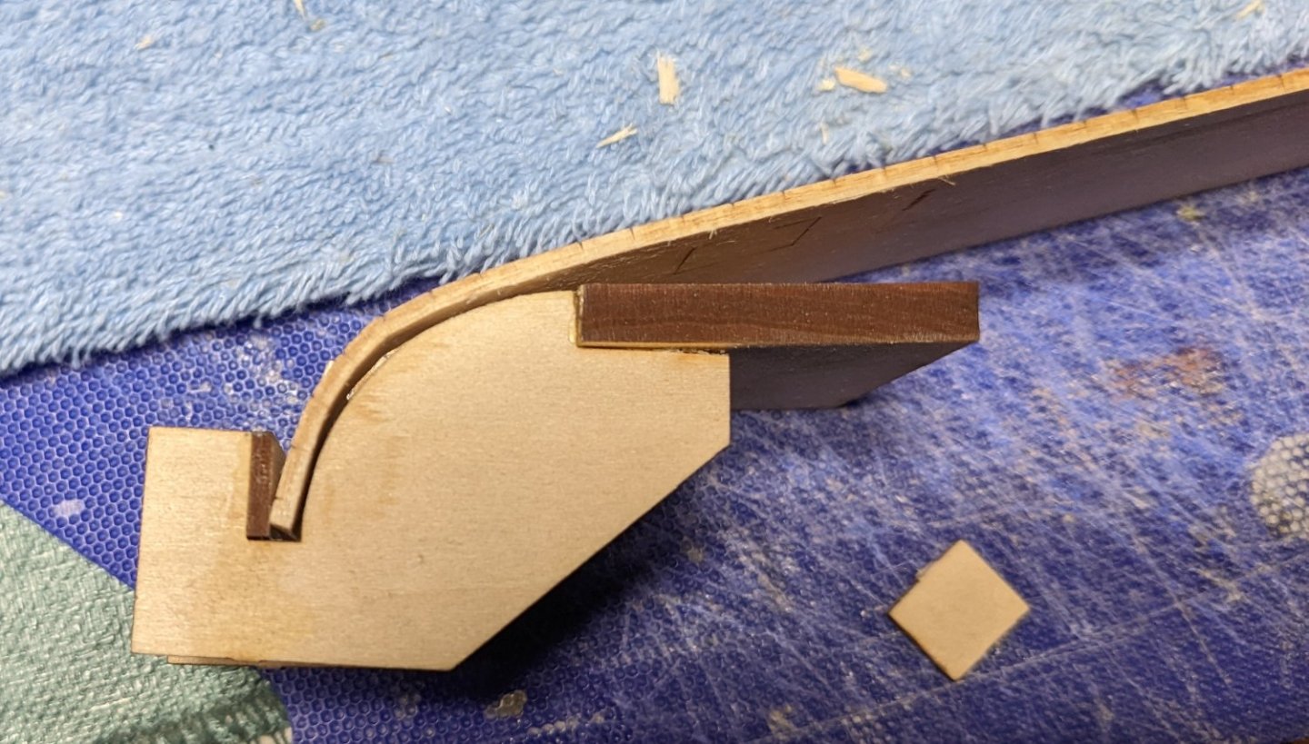
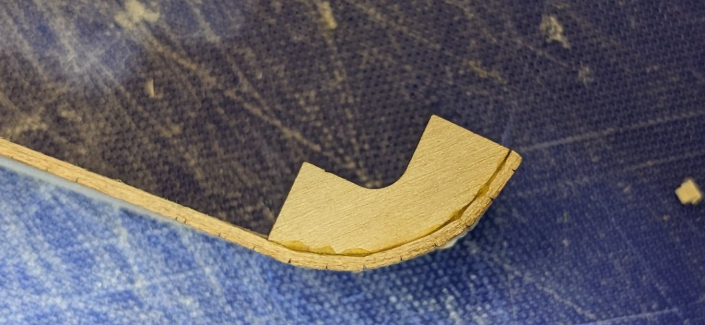
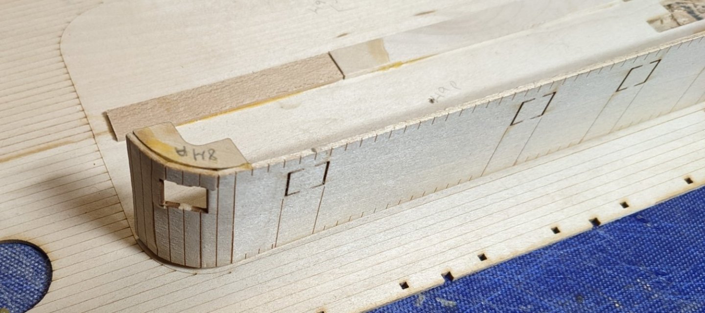
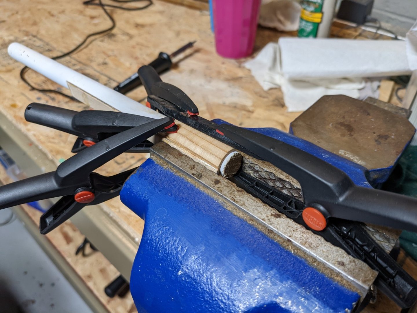
It has been awhile since I last posted... Lots of non-model building activities had grabbed my attention. I should be back at it for awhile. 🙂 Even though the main deck is not quite completed I wanted to try my hand at bending the four boiler deck walls. The sharp angles of those curves to me just seemed like a great opportunity to break the walls in the bending process. Especially since they want you to increase the slots in the wood to make it even thinner... and do it dry instead of wetting the wood. Anyway, knowing I would be breaking a lot of wood I wanted to practice those bends with some spare wood. I highly suggest you do that if you can. After breaking a number of test pieces trying to get the curve correct, I found a way that for me that worked well for someone of my limited skill level. For the larger forward curves I did soak the walls but instead of initially bending them in the supplied jig I bent them around a 1 1/2" PVC pipe. The problem with wetting the wood and using the supplied jig is that the wood wavers between the three jig curved sections. If there were maybe 5 curved sections in the jig instead of just 3 then wetting the wood probably would not be an issue. Wetting and bending around a pipe seems to have solved this issue. Once dry the final bend is pretty close to the required bend. Just a little off. At that point only rub a little water (so not to cause the walls to warp) on the wall and then put it into the intended jig. Since the jig is only putting in the final bend it works great and no danger of breaking the wall section End result is a curve that works and easily accepts parts 84A (top and bottom) to secure the curve And dry fitting to the boiler deck - should be ready for adding the battens and painting The aft bends are a little more difficult but the principal is the same. For these bends I used a 5/8" down rod to bend the wall around. That turned out OK but the bend was a little too sever. If you choose this method to bend you walls I might suggest trying a 3/4" or 1" dowel (or pvc pipe). Even so, after drying, re-wetting, and putting into the intended jig, the outcome is the same. A pretty good bend for the back wall. No matter how you choose to bend your walls,,,, practice, practice, practice on spare wood before actually bend the walls. It will save you a lot of tears.


- 157 replies
-
- 4
-
-
- chaperon
- Model Shipways
- (and 1 more)
-
Brian, Thanks for you comments on the alignment, but I think I have it..... or at least the alignment with the main deck and the boiler deck. I learned the alignment lesson the hard way on the King of the Mississippi. That was one of my earlier models and I did not think about alignment until it was too late. Paid the price for that lesson. As for the cleats.... thanks for beating some sense into me... I had cleaned them up before mounting them, but I agree, they need to be painted. I should be able to paint them in place.
- 157 replies
-
- 2
-
-
- chaperon
- Model Shipways
- (and 1 more)
-
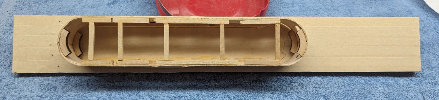
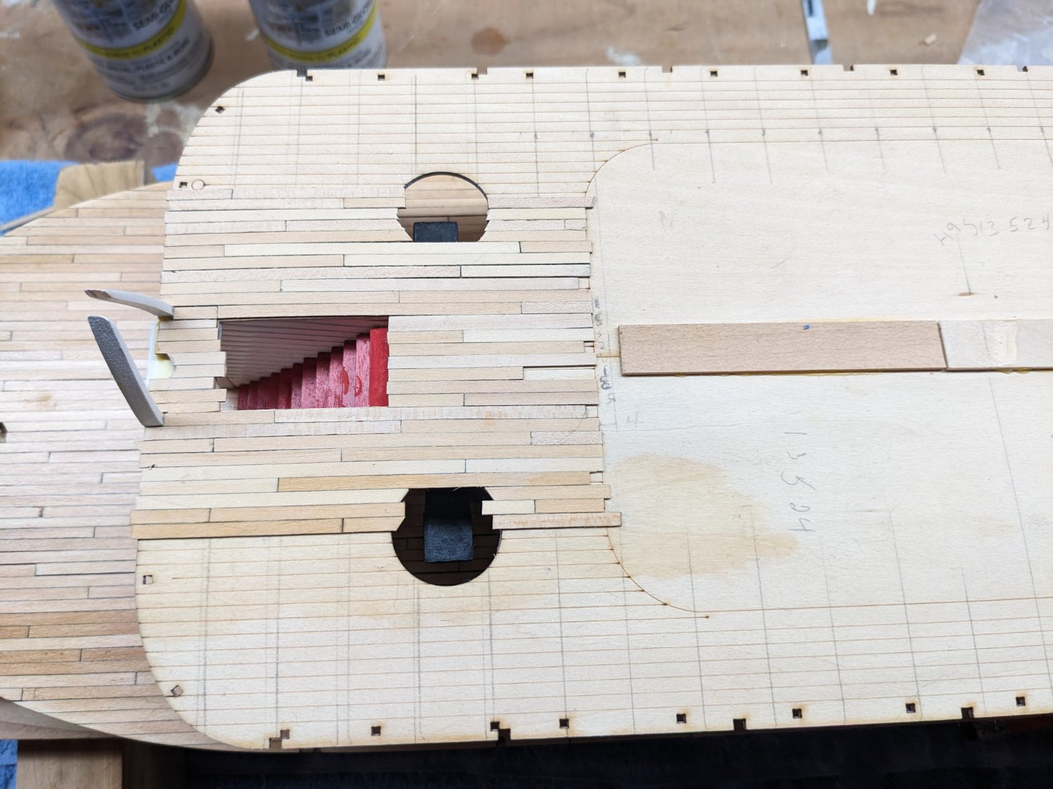
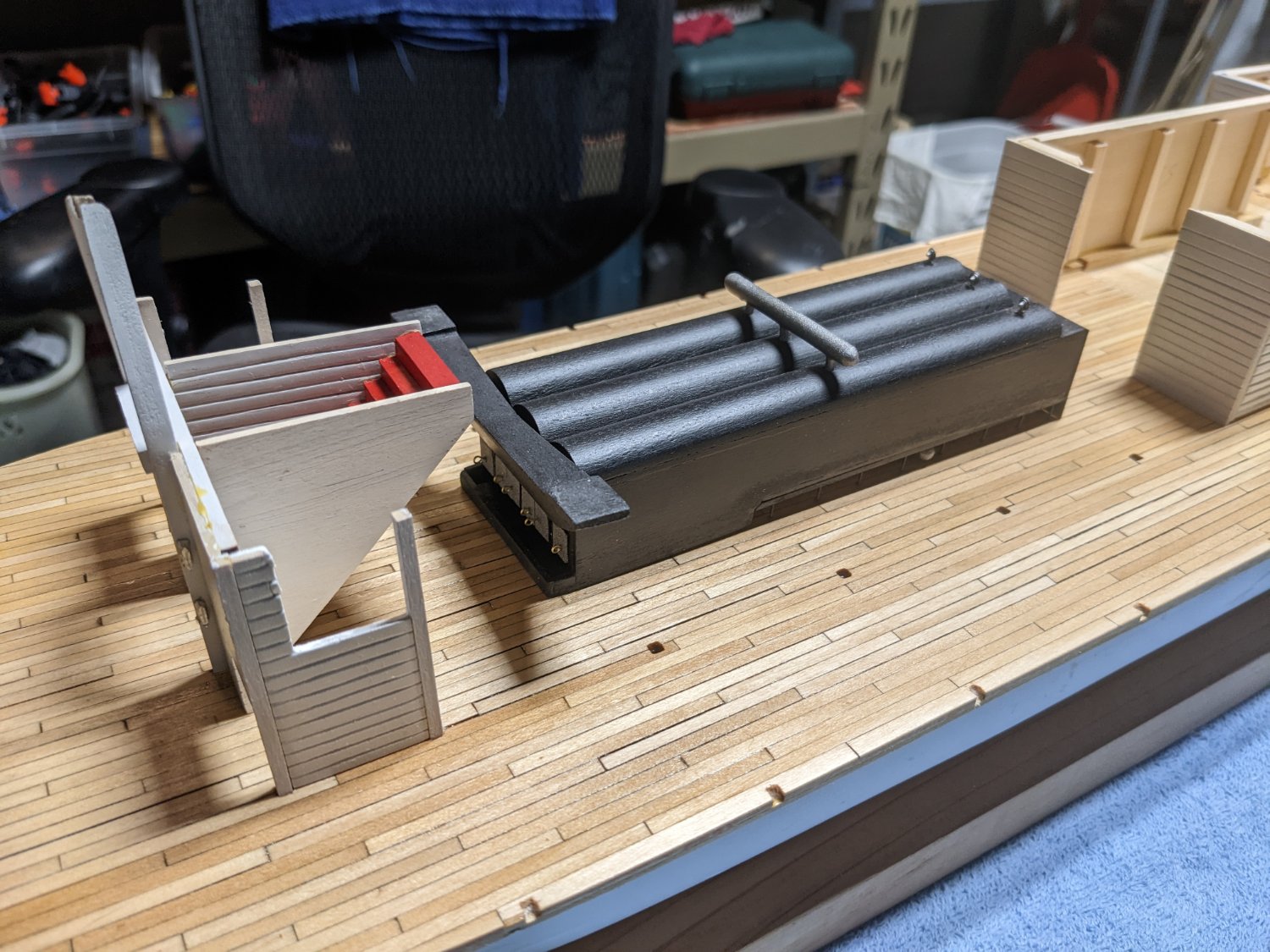
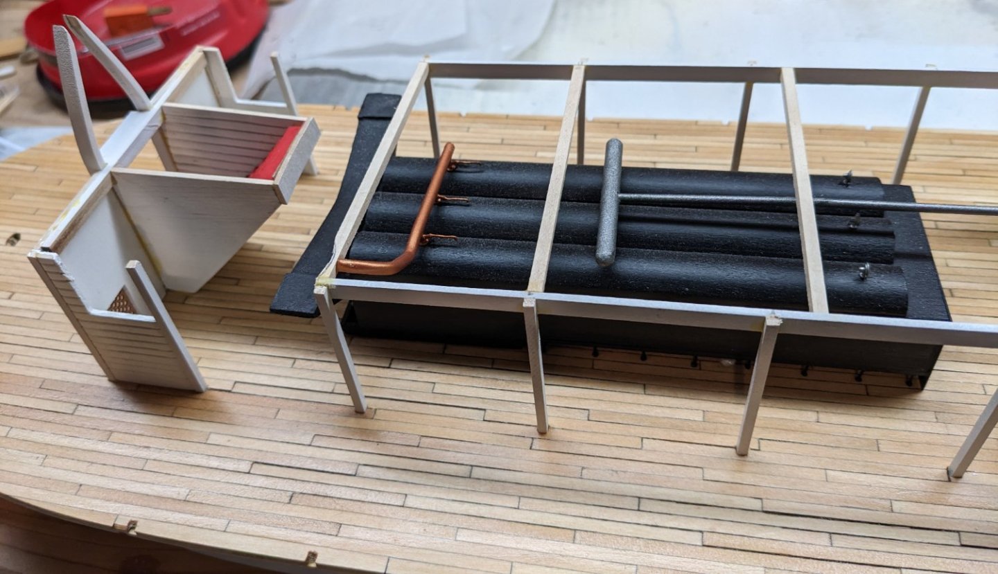
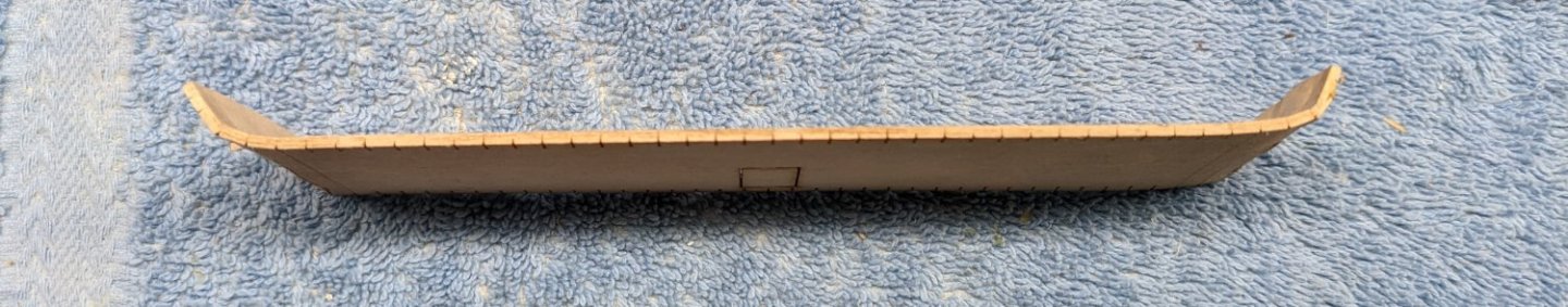
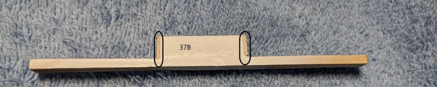
With all the main floor parts prepared and painted, started the assembly. When I came to part 37B (the part above the main door way, it seemed to be a bit (1/16") off. Probably due to lack of builder skill, but I am going to rack it up as variations in the wood. Thus two 1/32" scrap pieces were added to each side of the piece. Seemed to fit better at that point. Will add some paint and glue into place. Also note I left the cleats unpainted. To me, I just like the look of metal cleats.... Not realistic, and I may paint them later on,,,, but for now, I need to think about that. 🙂 Assembly continues As mentioned earlier, boiler system not glued in at this time. I wanted to dry fit the boiler room floor (main floor ceiling) just to verify the exact location of the boilers When preparing the boiler room floor (parts 49 A/B & 50 A/B) it talks about turning them over and gluing some small strips of wood along bottom (main floor ceiling) to strengthen the seams. It also makes note to place them where they will not be seen or interfere with any of the main floor structures. Rather then doing that I choose to place the strips on the other side where I know they will not be seen and will not interfere with any structures. Hope I am not shooting myself in the foot here, but it seems like a good thing to do. Time will tell. Finally, laying the boiler room floor pieces in place I can exactly place the boiler in order to correctly accept the smoke stack covers. Picture is not completely accurate as it seems the boiler moved between lining it up and taking the picture, but you get the idea. To me, with my lack of skill, (and variations on wood), there is no way that boiler would have lined up correctly if I just glued it in place where it was indicated on the plans. It would have had to have been off by a little bit. This way the stacks will line up and if the boiler is 1/32" or 1/16" out of place it will not be noticeable.


- 157 replies
-
- 5
-
-
- chaperon
- Model Shipways
- (and 1 more)
-
Brian, Yes I used the 1.6mm and the 1.2mm rivets from Model Motercars. Below is the exact description Item SKU Rivet - 1.2 mm Head Diameter - Brass - RT12 Rivet - 1.6 mm Head Diameter - Brass - RT16 1.6mm rivets are great for the larger ones, but I might suggest the 1.0mm or maybe even smaller for the smaller rivets. As you can see on my model, the 1.2mm rivets kind of overwhelms the parts they attach to. I think smaller would be better for those. As for the heads of the rivets, I cut off most of the shaft but left a little stub to insert into a drilled hole. In order to do that you need a .5mm drill bit. If you have one, then drill a small hole and with a touch of CA glue the rivet easily sticks into the hole. If you do not have a .5mm bit then you would have to cut off the head and attach with CA. John
-
Brian, Thanks for your comments,,,, as for the "added walls for the front of the machine room", I kind got the idea (or stole the idea) from your log. You built a really neat wall structure of cargo crates to help cover the opening. They look great and add a nice touch to the model.
- 157 replies
-
- 2
-

-
-
- chaperon
- Model Shipways
- (and 1 more)