John Gummersall
-
Posts
265 -
Joined
-
Last visited
Content Type
Profiles
Forums
Gallery
Events
Everything posted by John Gummersall
-
 Yves, Totally agree with you.....This one and King of the Mississippi (also a steamship) are really easy to plank compared to other ships. It will get harder (for me anyway) as I build up the ship.
- 158 replies
-
- 1
-

-
- chaperon
- Model Shipways
- (and 1 more)
-
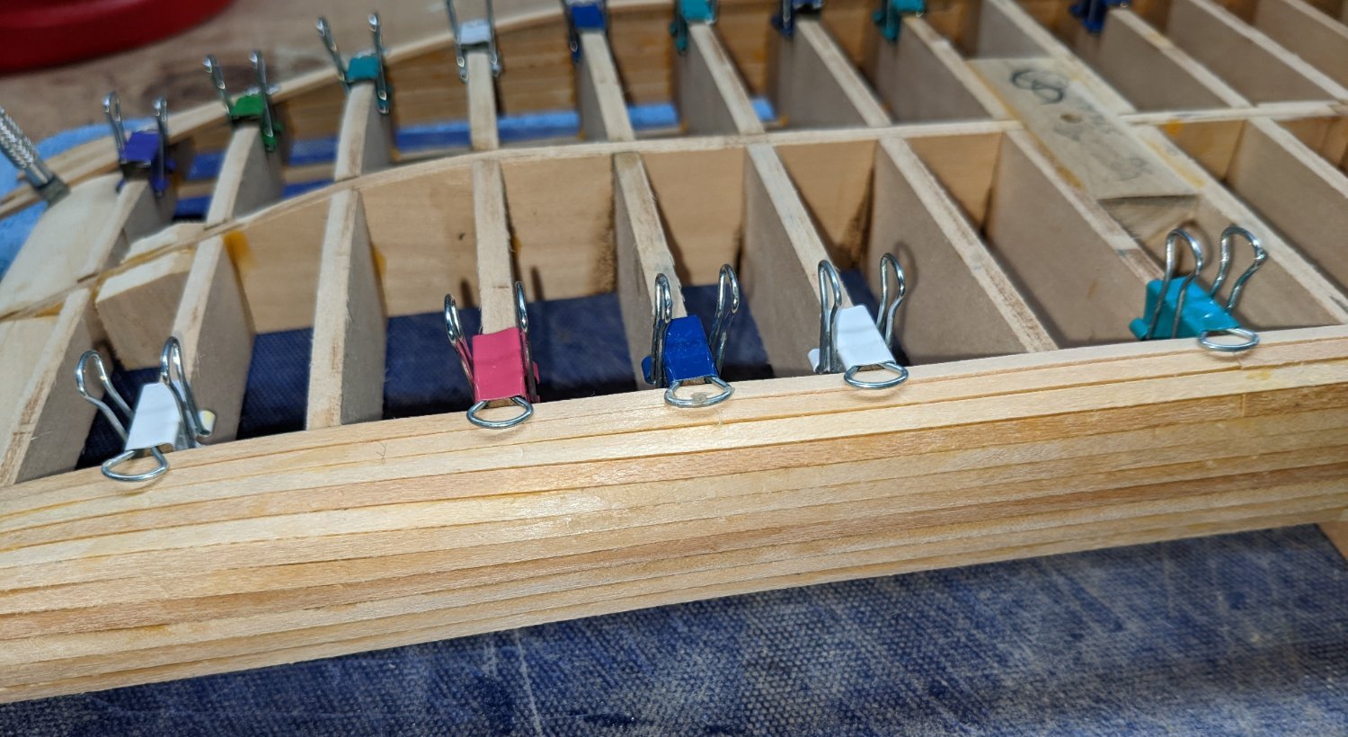
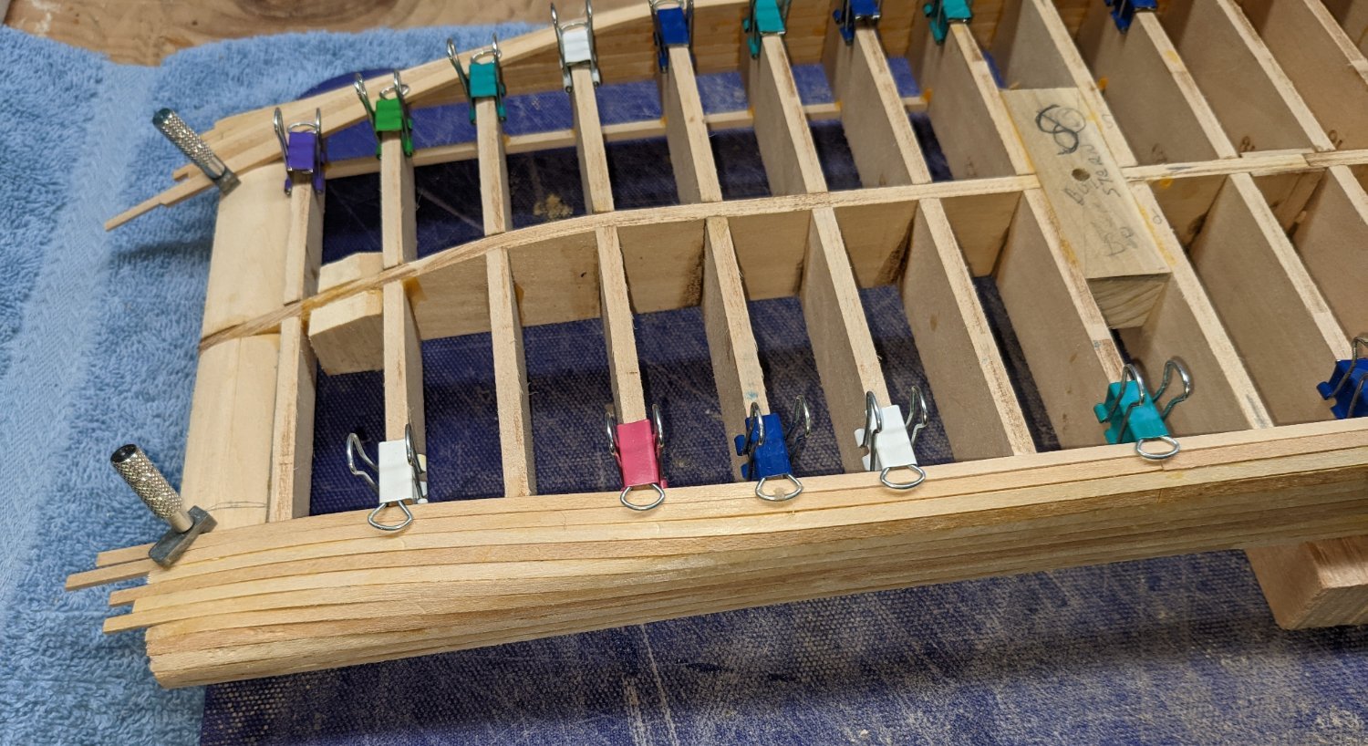
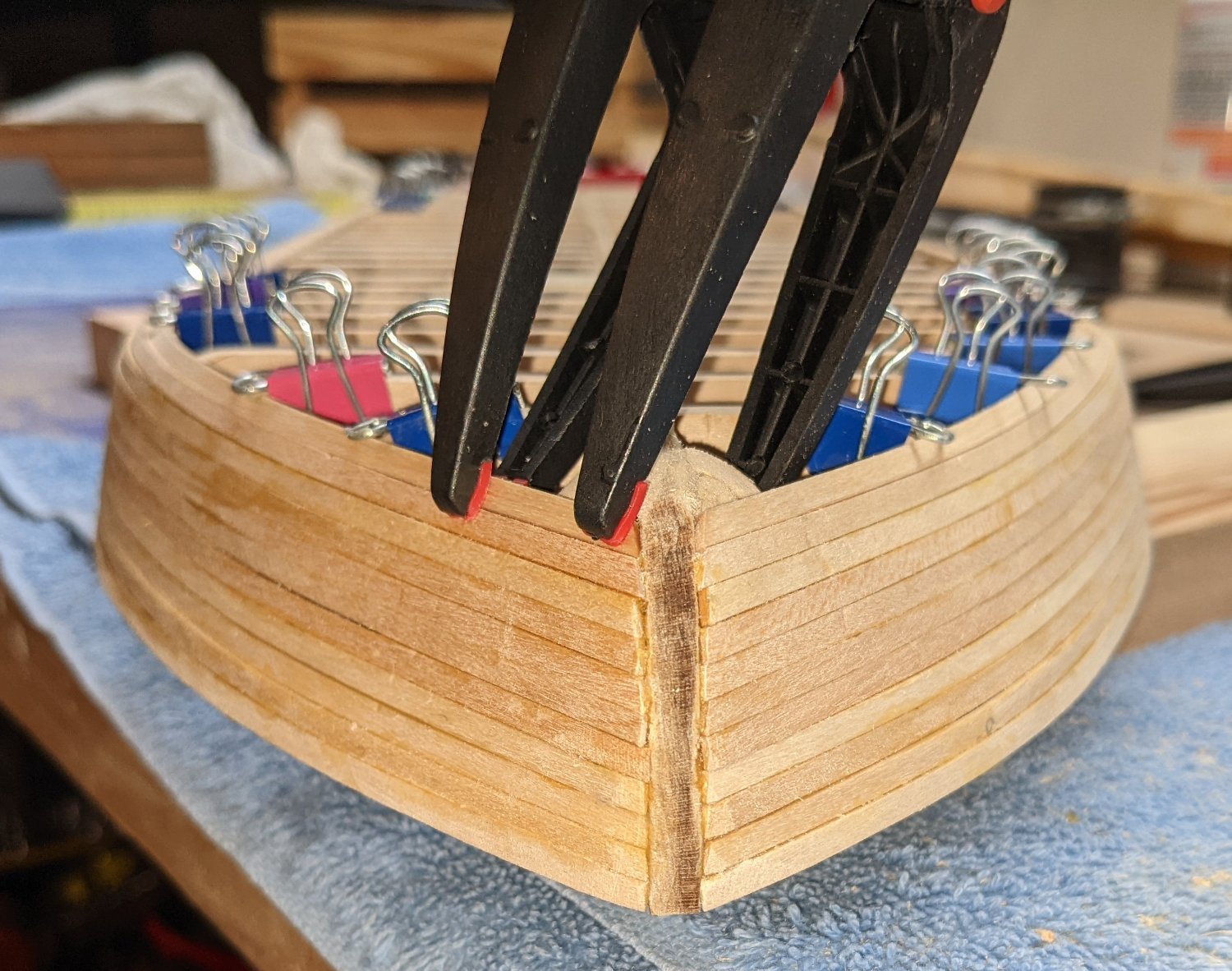
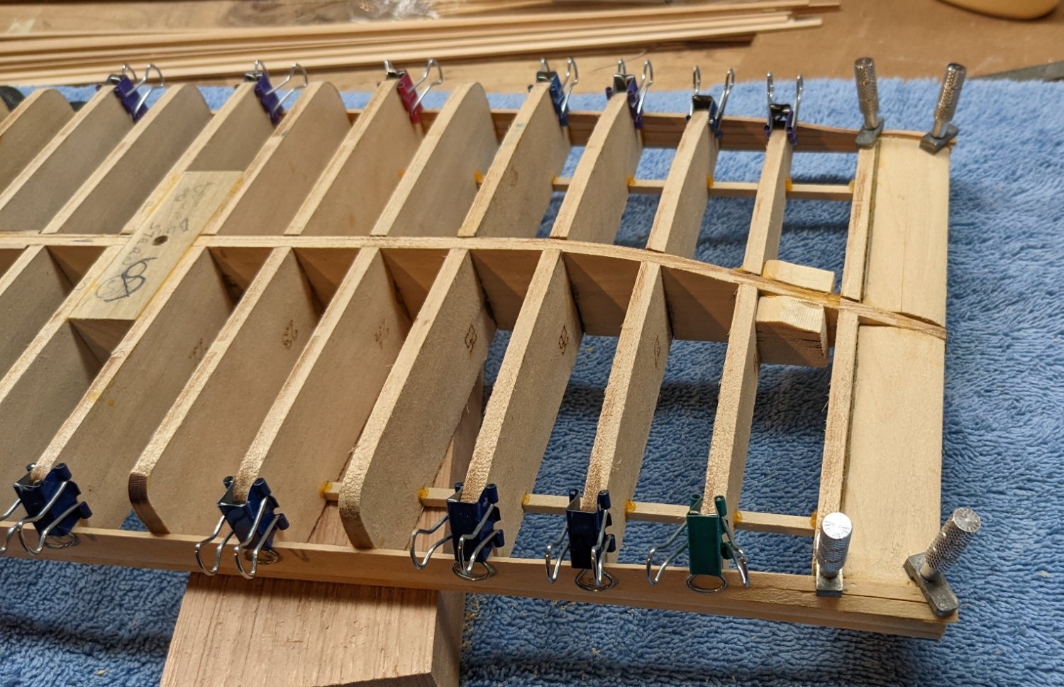
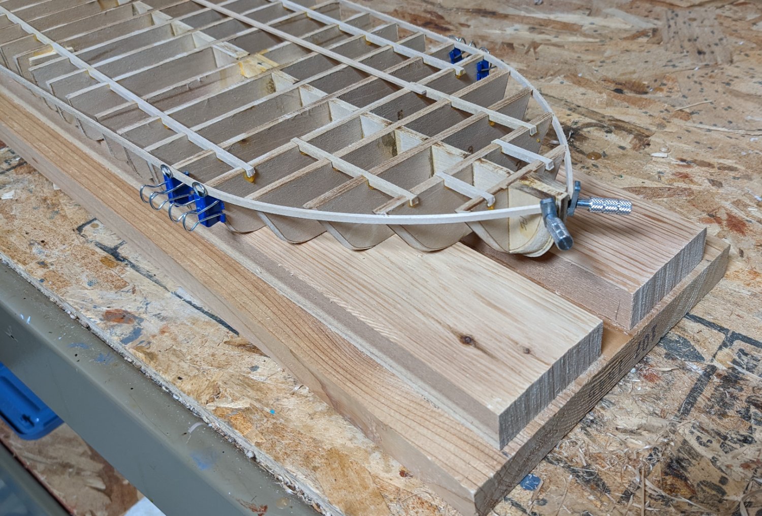
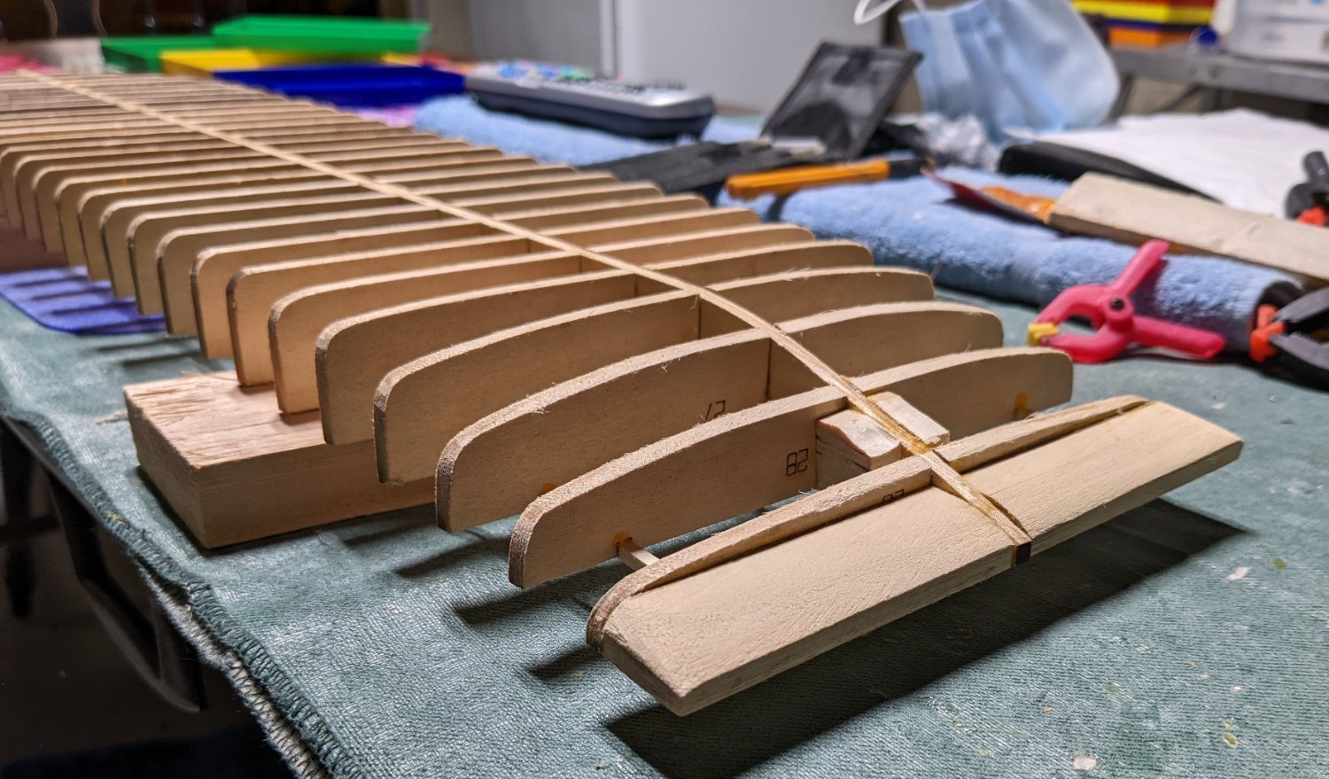
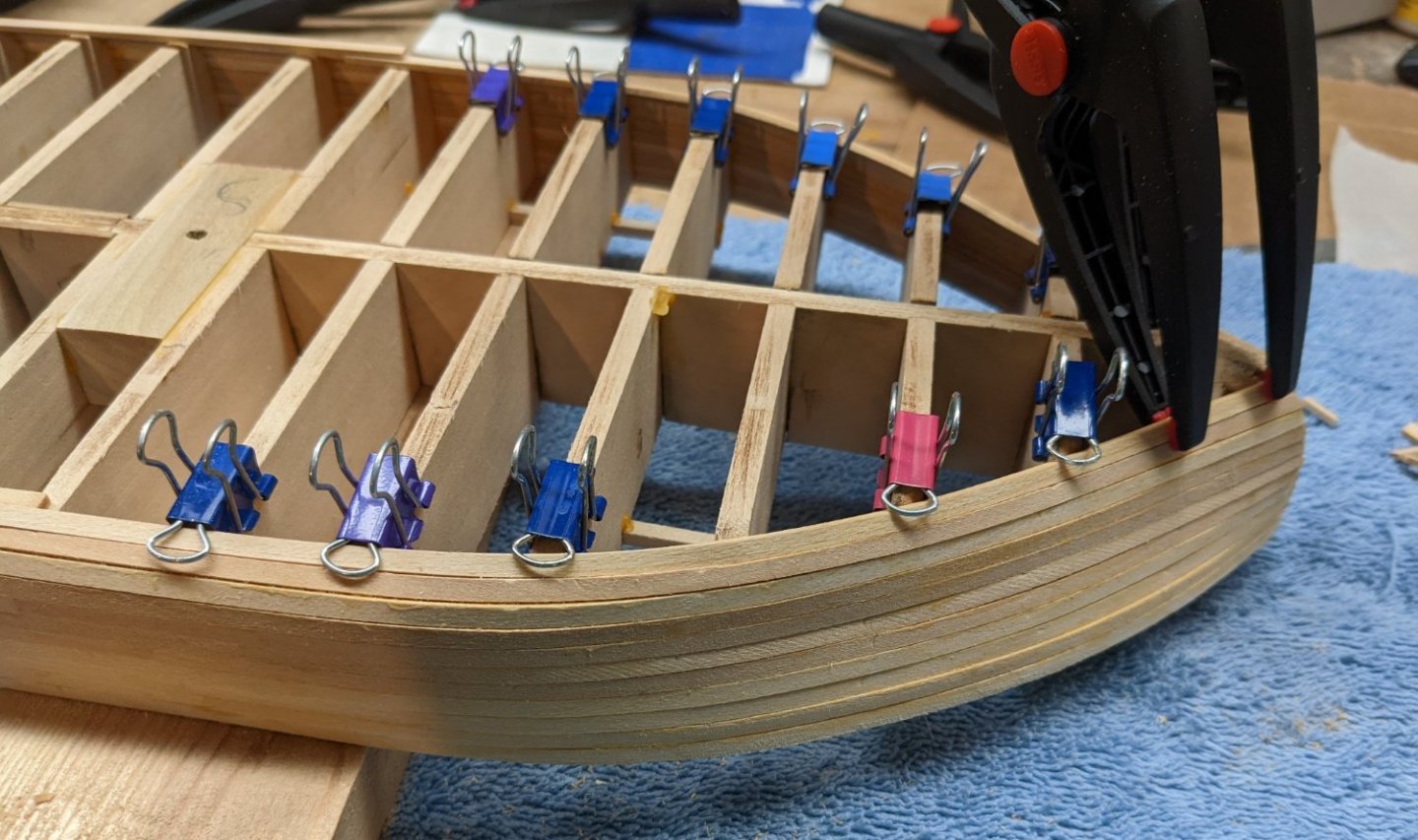
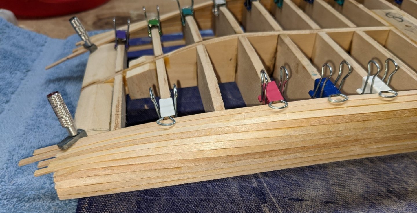
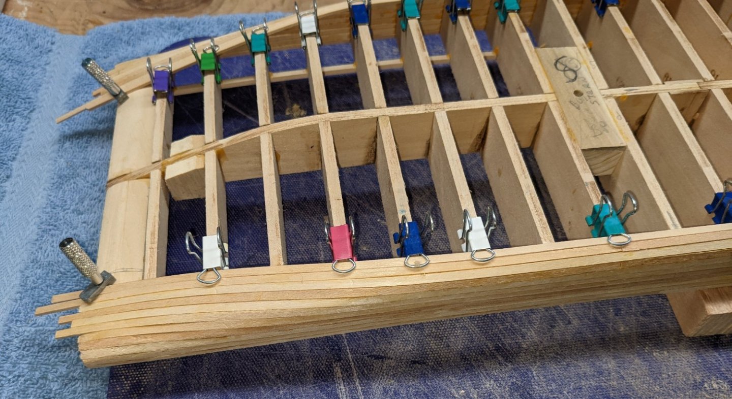
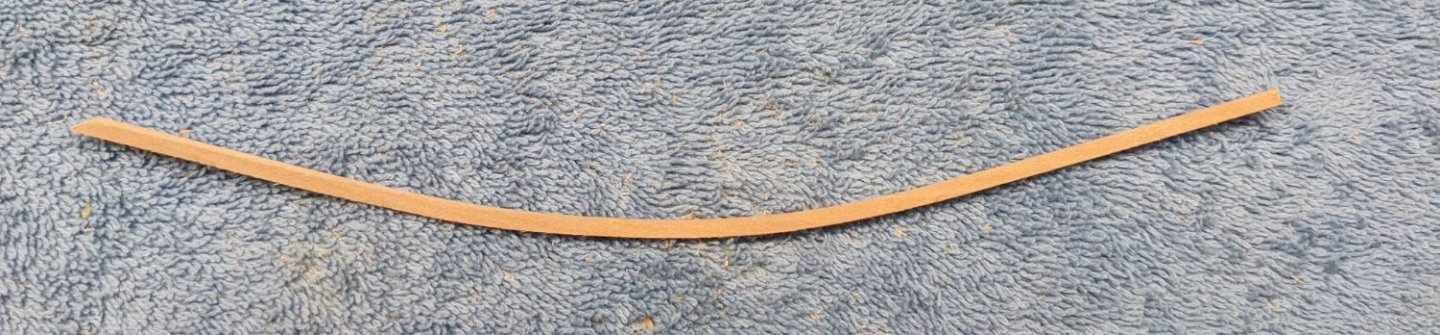
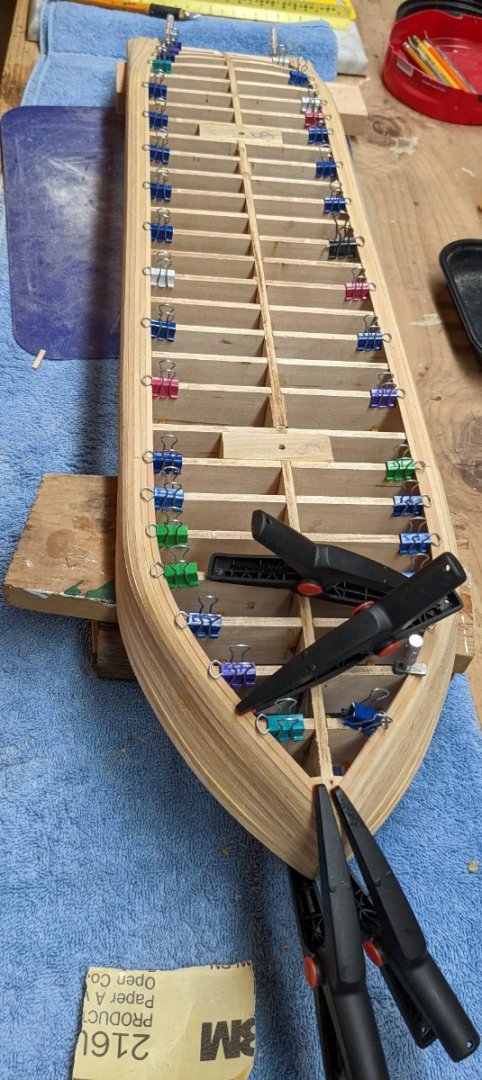
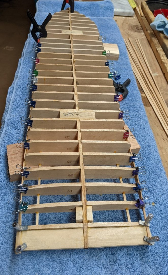
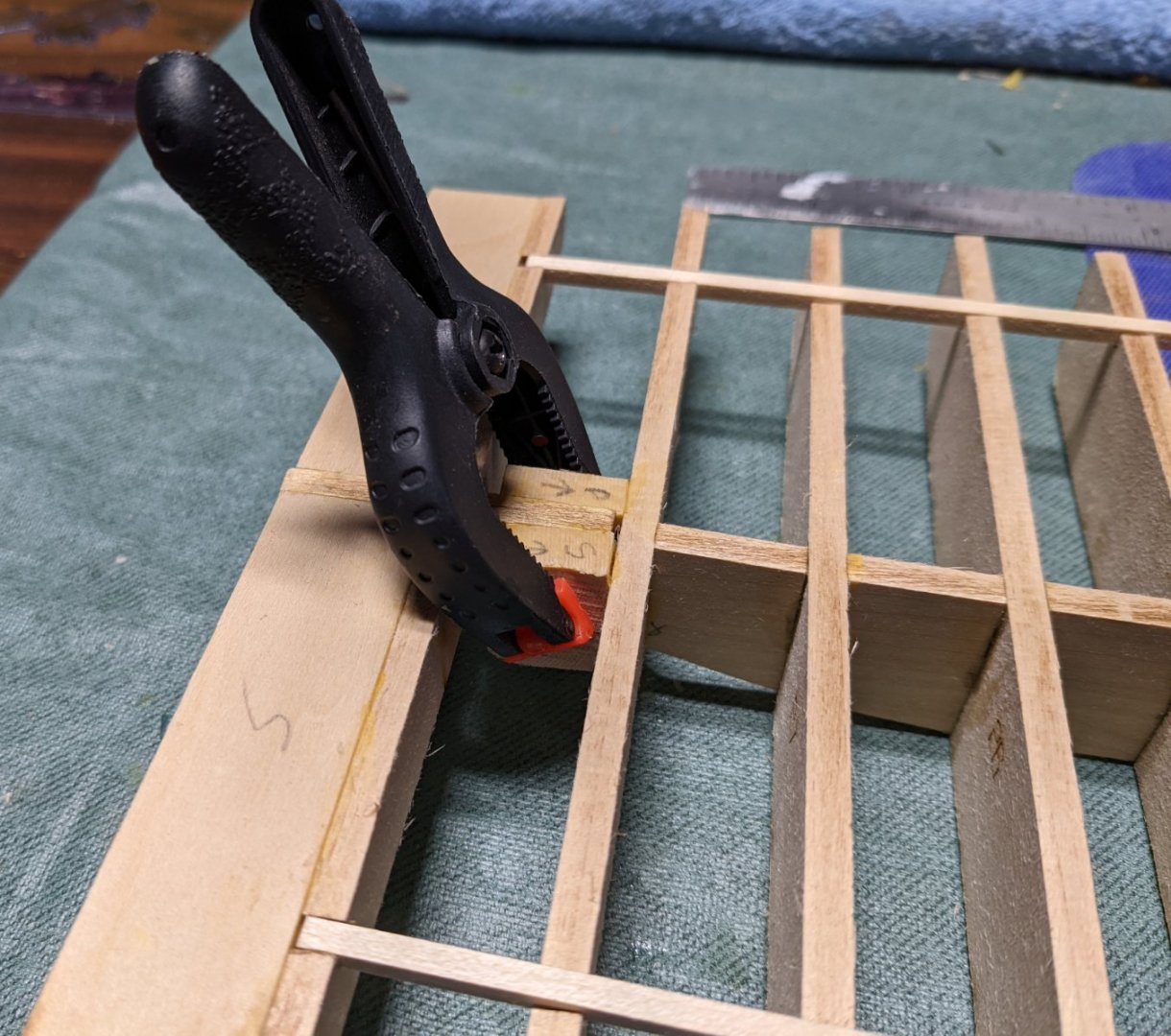
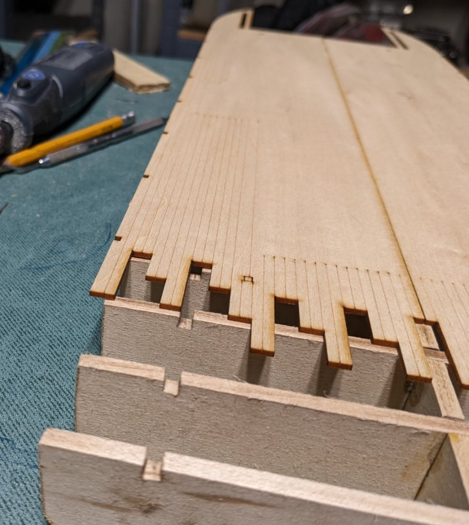
I am back,,,,,,, Early on I mentioned this would be a painfully slow log, but I did not realize just how slow it would be. With Spring in the air all sorts for outdoor clean-up tasks have been pulling me away for the boatyard. Seems the workers have gone on strike. Have completed planking to row 11. As other logs have indicated, with 1/8" planking, the planking effort is a breeze. With only a minimum amount of soaking, they ben very easily. Although for the first 10 rows they do not need to be bent very much. Even around the bow and stern sections, just wet, bend and clamp the planks until dry. After that they easily are glued into place. Only rows 10-13 require some real bending and twisting at the bow area. With the planks that are to be bent around a curve (bow/stern sections), be sure to trim the lower inside edge of each plank so they fit together better around the curve At this point A few bow shots And a few stern shots Here is one of the planks a the bow section in row 11.... Did I mention earlier they had some bend/twist to them? All 13 rows have been completed.... Next need to trim up the stern section and start laying the bottom 1/2" planks Did I mention "you can never have enough clamps"? This clamps with the screws really worked well keeping the stern planks in place.


- 158 replies
-
- 8
-
-
- chaperon
- Model Shipways
- (and 1 more)
-
Too Bad this log seems to die.... I was looking foreword to following along.
-
Brian, I only said I have resisted the urge to sand the planks at this point..... I say that now,,,, but I will no doubt be sanding in the near future. I too have never been successful holding off sanding the hull until all planks have been laid. Just can not help looking at those uneven planks and resist,,, "just a little sanding". That is what I tell myself each time,,, and then end up sanding the hull as I go along. 🙂 We will see how far I get into planking before the sandpaper comes out... I can hear it calling my name even now... john
-
I forgot to mention that on Acme Tools they cost $2.45 each.... If only need a couple the $6.95 may not be worth the cost, but I could not find them anywhere else for anywhere near that price. Be sure to check out Acme Tools (https://www.acmetools.com/plastic-spring-clamp-2-inch-capacity-xcl/091162000687.html). As mentioned earlier they are currently out of stock for online shoppers... 11 of by 12 clamps are waiting on back order... We will see if the 3-5 week wait time they listed is anywhere near accurate. john
-
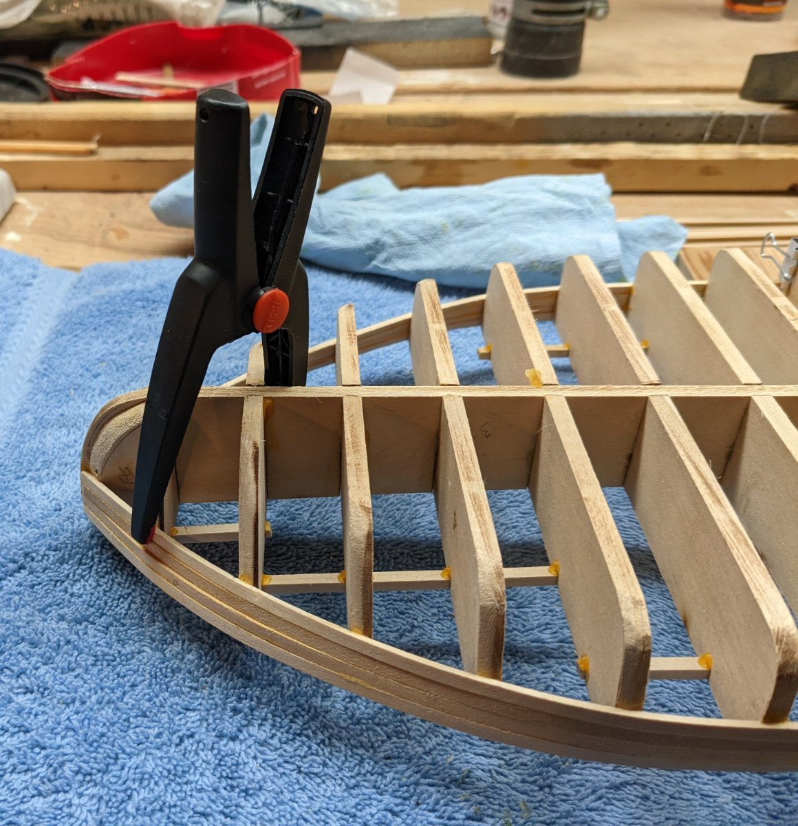
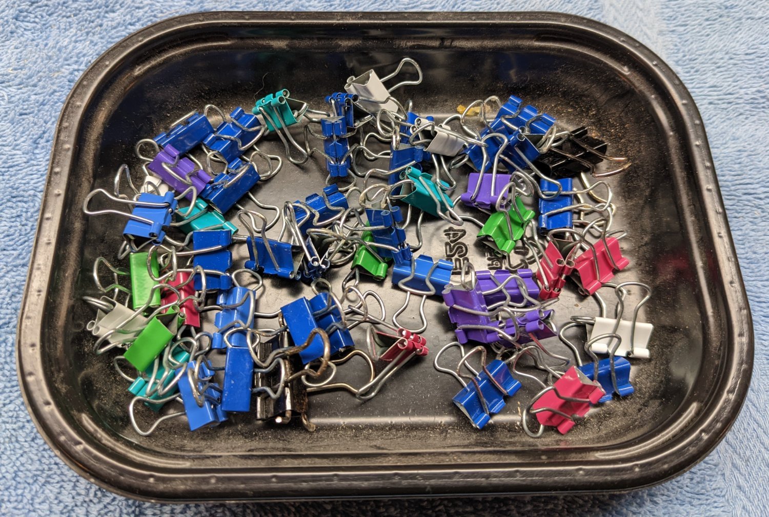
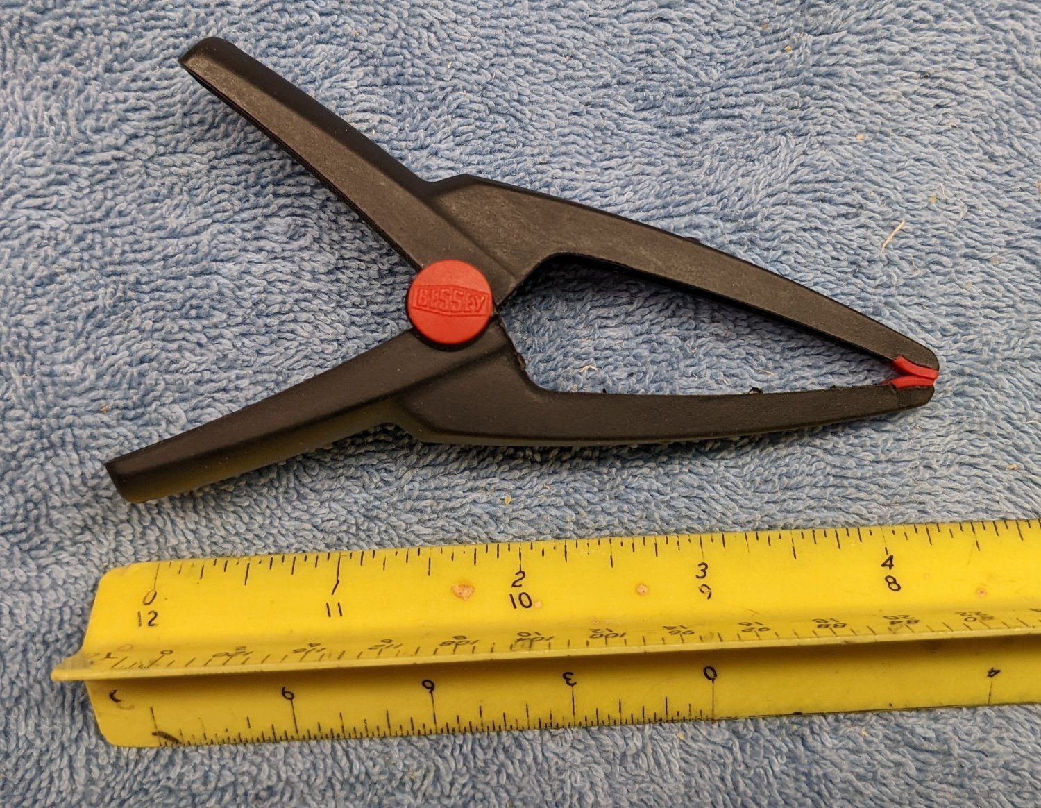
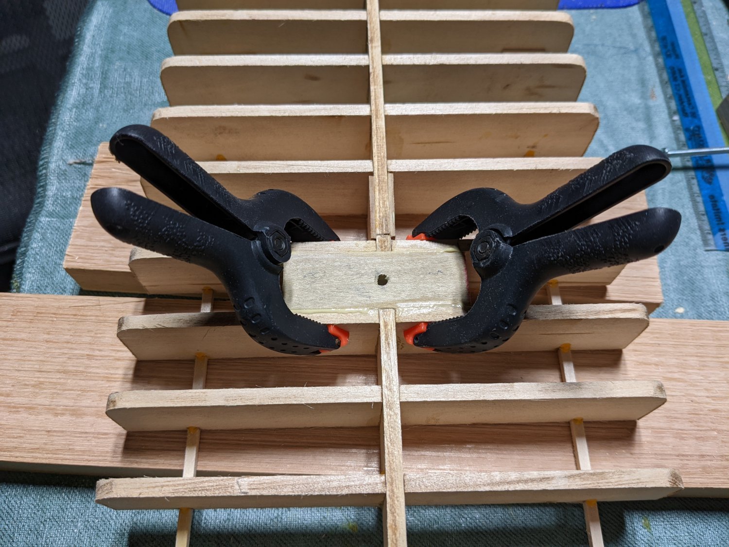
Bob, Glad to have you follow along and feel free to ask me any questions as I go alone... especially if you see a place where I might have made a potential error. I am by no means an expert builder. Unfortunately this build has turned into one of those painfully slow logs. Spring has come and with that goes all sort or tasks (indoor and outdoor) that now need attention after being ignored all winter. I have not stopped, but updates may be slow in coming. At this point I have completed the first 4 rows,,,, I have to say, as the instructions indicate, with 1/8 x 1/16 planking, the planking effort is pretty easy. As mentioned above, just soak for a few minutes, pin in place until dry, then glue. Only trimming I did was on the the bottom of the planks (The part that is glued to the bulkhead). Here I just took of the inside edges so the planks would fit better together over the hull bends. And after the clamps come off,,, I am resisting the urge to do any sanding until all the planks have been laid. A few dents in the wood here, but being basswood, I am hoping after I apply a little water, that the dents will come out,,,, If not there will be plenty of filled later on before painting, Since this is not a beginner model, I have a feeling what I am about to say will already be known, but for those of you who are in the market for some more clamps, I would like to point out some really good clamps. My most recent purchase was some 2 "BESSEY Plastic Spring Clamps. They really are useful for getting into those hard to reach areas. They are listed a 2" clamps, but as you can see, they are about 4" in length. I assume the 2" refers to the grip. You can get them are various places online, but I found the best price is directly from Acme Tools even with the $6.49 shipping. The shipping charge is not much if you are ordering a bunch of them. I my case I ordered 12, but at this time only have 2. The other 10 are backordered. Supply chain issues,,, Web site says they should ship in 3-5 weeks. That was 2 weeks ago, so we will see how accurate that information is when they actually arrive. And of course every modeler has these clamps.. If not, you need to get them right away... They are used on every model. An finally, these clamps are also very useful when planks need some extra (shall we say) "persuasion".


- 158 replies
-
- 4
-
-
- chaperon
- Model Shipways
- (and 1 more)
-
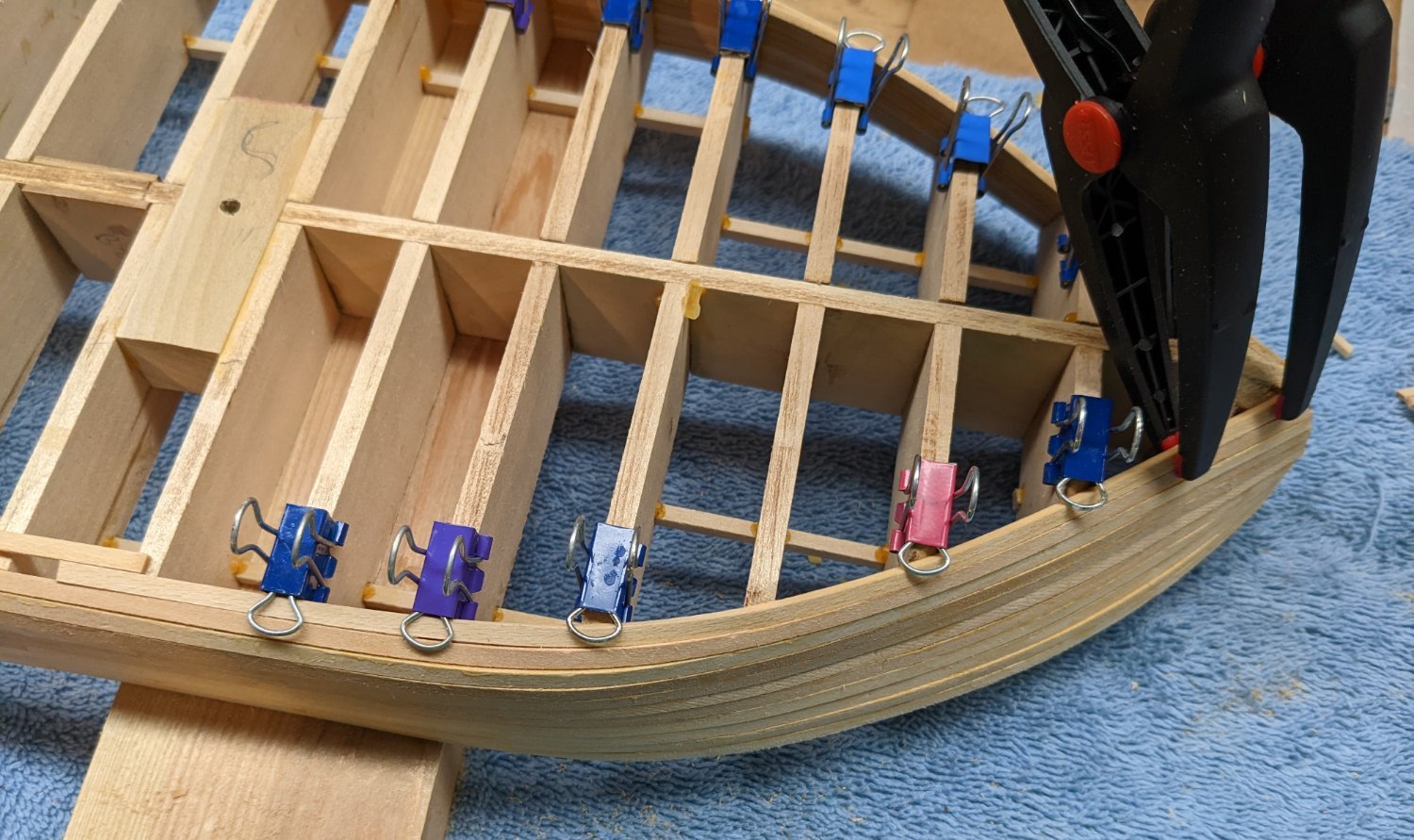
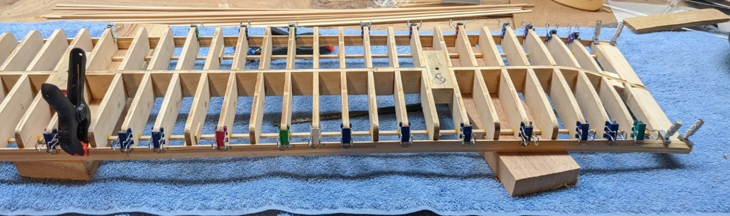
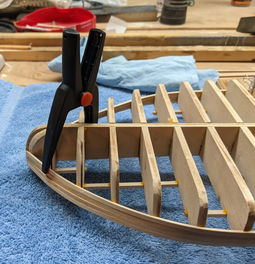
Drying over night in my make-shift jig did the trick. The stern piece is now parallel and no longer has a tilt. Stringers are all in and we are ready to roll with planking. For the planking I have the hull sitting on the temporary stand. It is not bolted in, but it turns out the stand is a very level stable area to hold the hull. Not sure I will plank the entire hull on the stand, but at this point it seems like a good idea. And so the planking begins.... First two sheer planks at the bow section have been soaked and clamped into place to dry. The 1/8 x 1/16 planking is so thin that only about 10 minutes of soaking is required and the plank is very pliable. With 13 planks, I would expect it to take be about 13 days to complete the planking as each plank needs to be soaked, dry over night, and the glued to the hull. I am not going to rush the drying time as I really do not want to risk the wood (if still wet) to shrink after it is glued to the hull. Even though I plan to fill and paint the hull, I want to do the planking a even as possible with minimum gaps. Practice for other hulls in the future that do not get painted.

- 158 replies
-
- 6
-
-
- chaperon
- Model Shipways
- (and 1 more)
-
Brian and Cathead.... Thanks for your comments,,,,, makes me feel better that I am not that crazy....
- 158 replies
-
- 3
-
-
- chaperon
- Model Shipways
- (and 1 more)
-
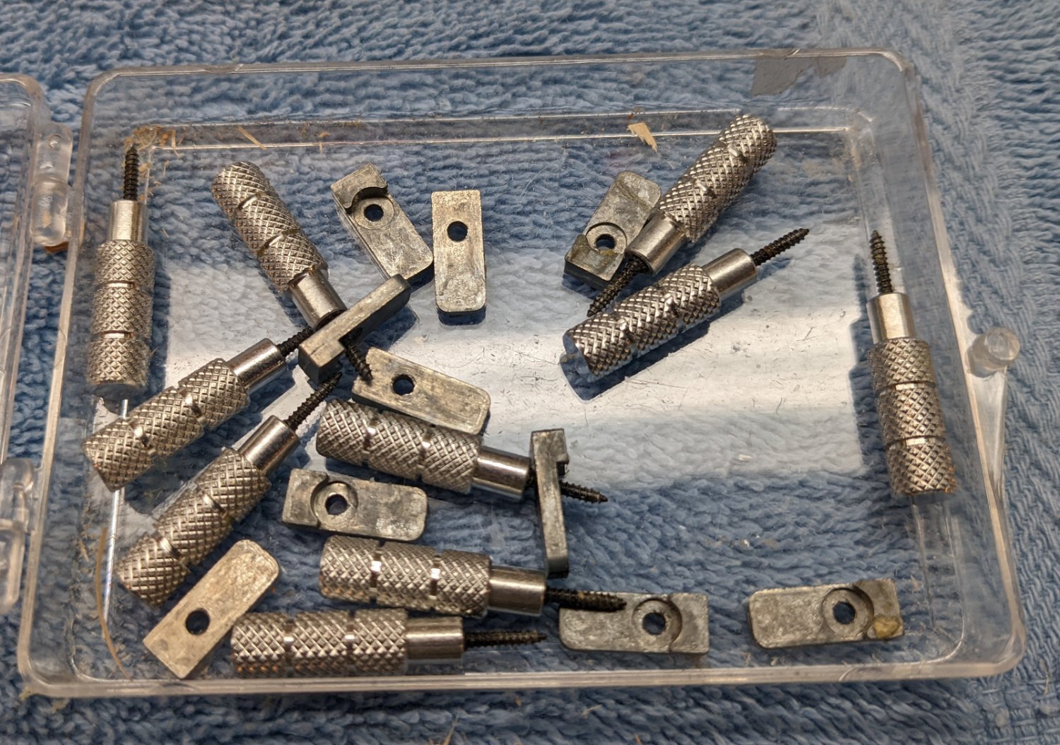
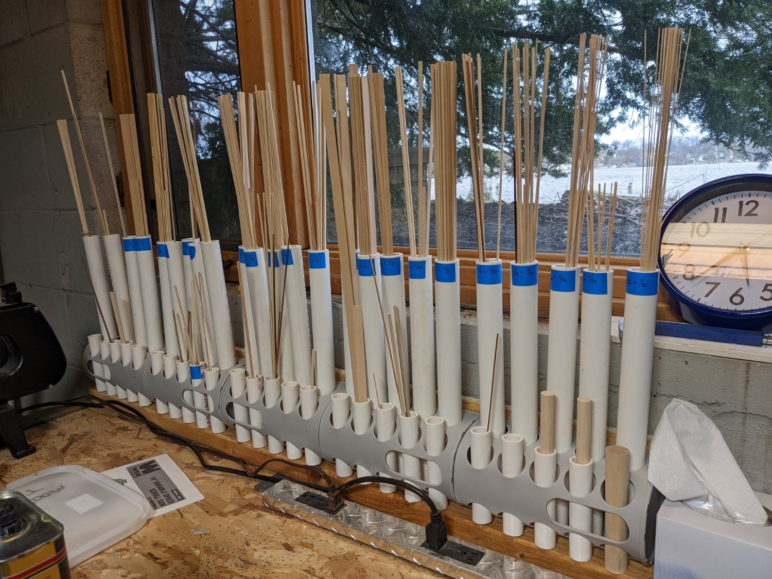
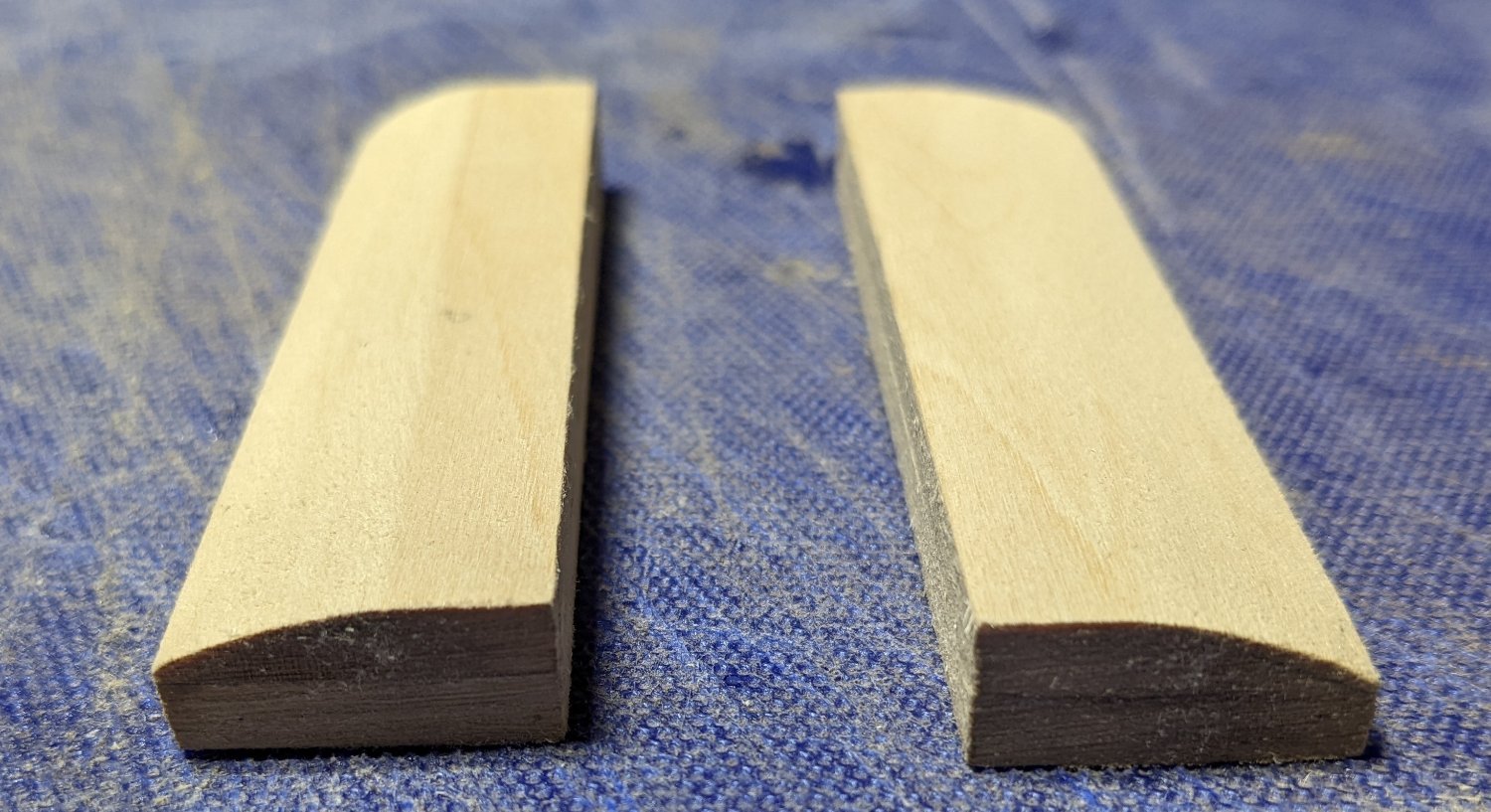
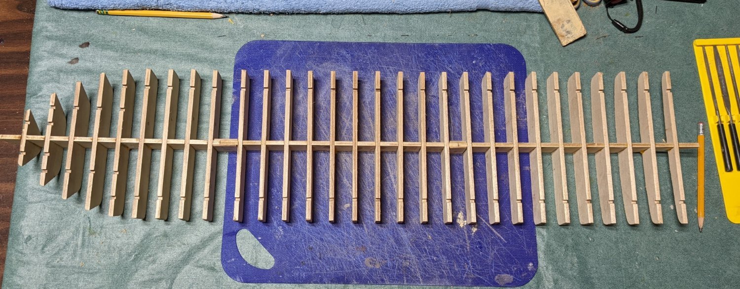
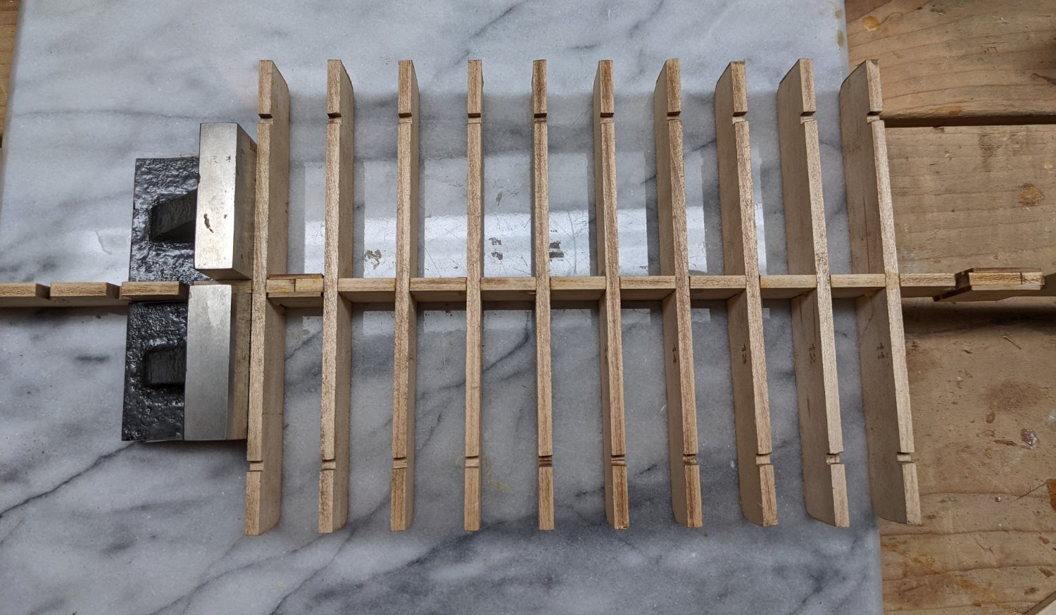
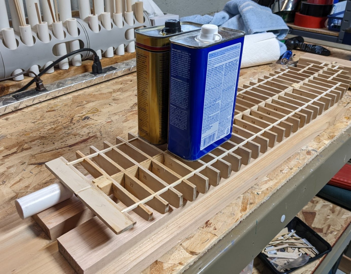
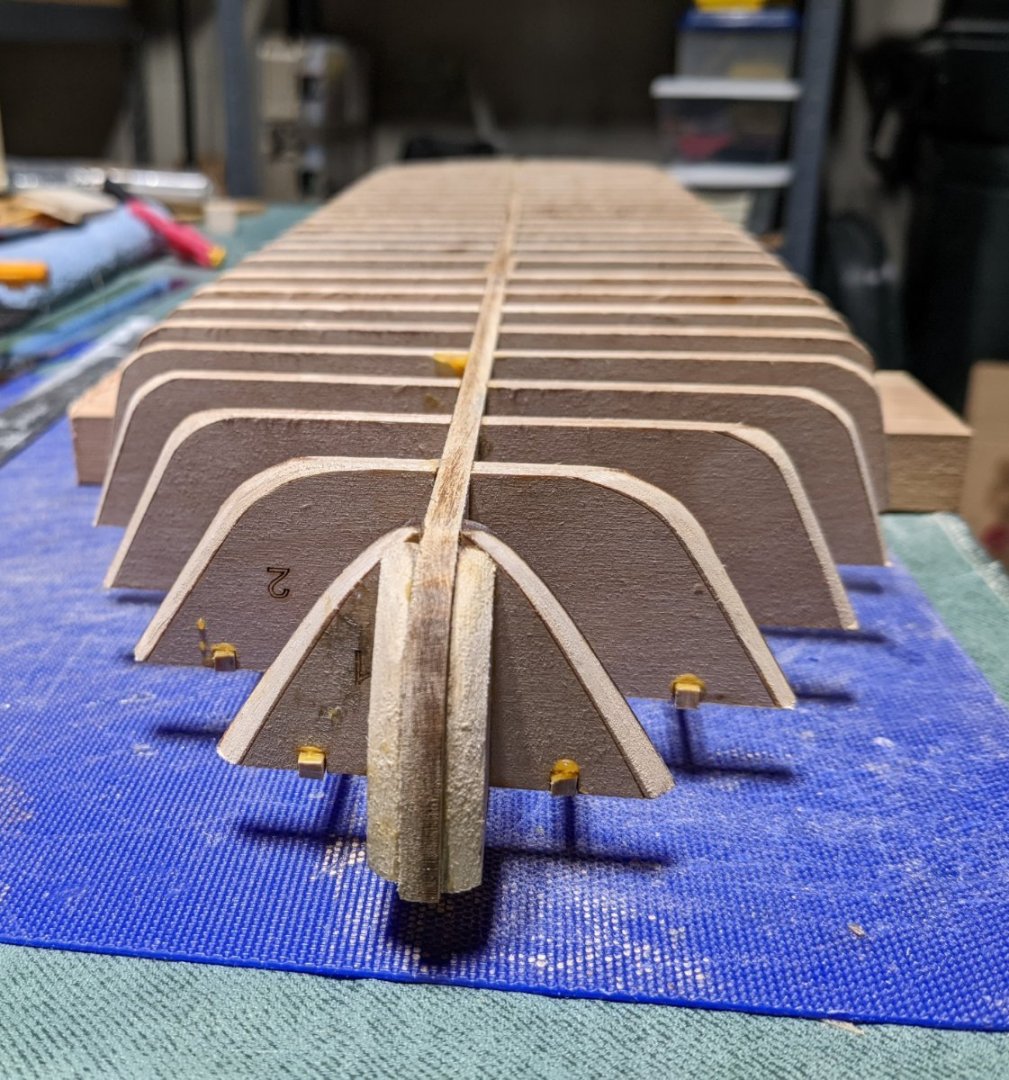
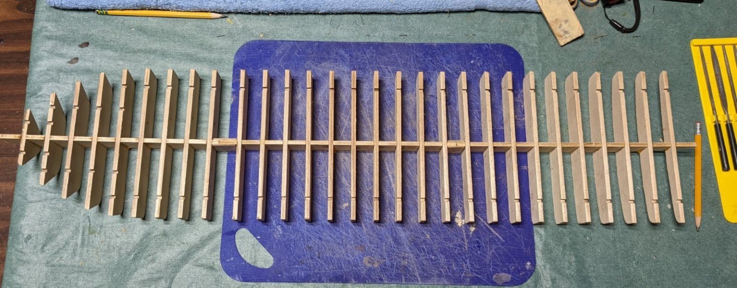
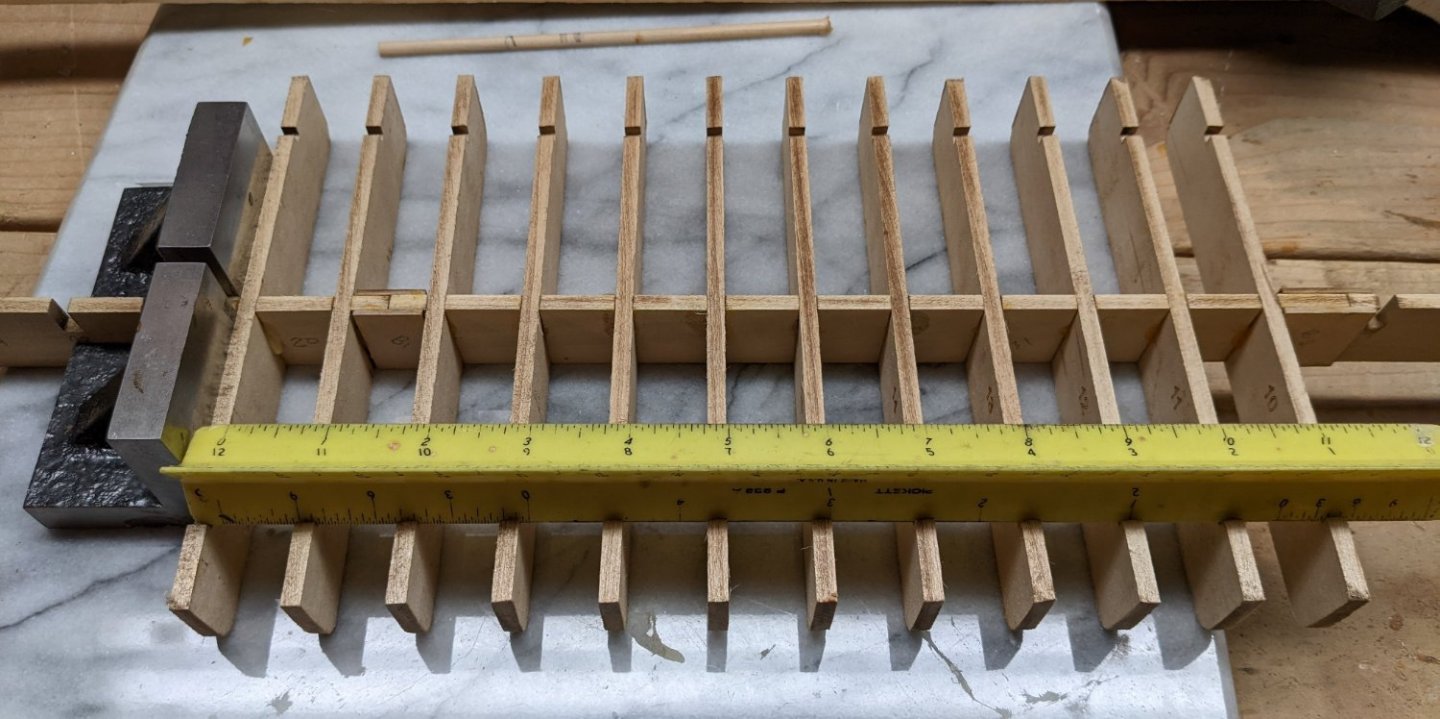
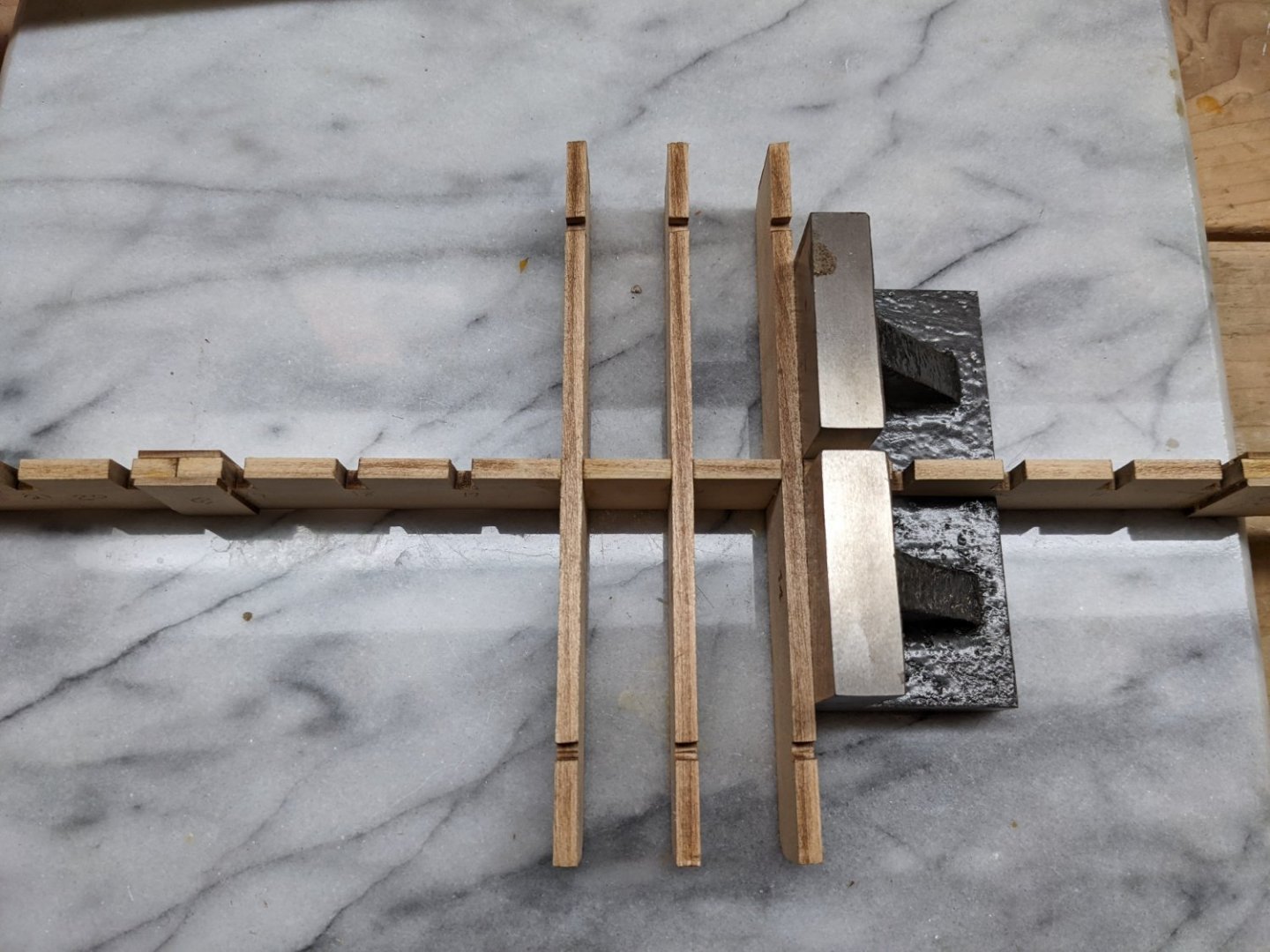
That slight tilt in the stern got to bugging me. I just had to try to fix it. Below is my attempt. I soaked the last four bulkheads and then jury-rigged up something to try to straighten it out. We will see what happens tomorrow when things dry out. More experienced modelers will probably get a good laugh at my expense, but I have always had a hard time keeping track of the various wood strip sizes. I have tried laying it out on a table, labeling them with paper and clamps or rubber bands. Labels seem to fall off especially with the very thin wood that only has a few strips. And over time, left over wood from previous models just adds to the confusion. Nothing seems to be a good solution. Seems I always end up digging through a pile of wood trying to find the correct piece. Anyway, I had some spare 1" PVC pipe around and started playing around. Below is what I came up with... Not elegant, and maybe even a little crazy, but for my simple mind it seems to work. The taller pipes in the back are 14" and labeled with tape. The shorted pipes in front are 3/4" and 5" long. They hold the same size as the larger pipe in back but for wood strips shorter than 14". I used tape for labels as it seems there are countless sizes of wooden strips and easier to change a tape label than if it was permanently marked. In this rack there are 25 slots so I can account for a number of different sizes. Once complete I added the wood from the Chaperon and other wood left over from other models. I have to say, while some may laugh, I really like the idea of being able to go right to the size of wood I am after rather than continually digging through a pile of wood. Just thought I would share... but I know some will think I am crazy.

- 158 replies
-
- 7
-
-
- chaperon
- Model Shipways
- (and 1 more)
-
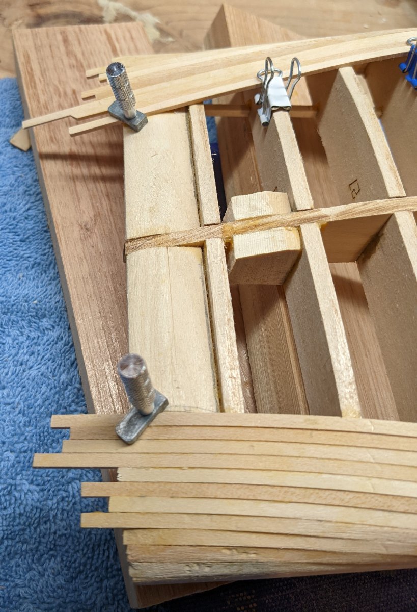
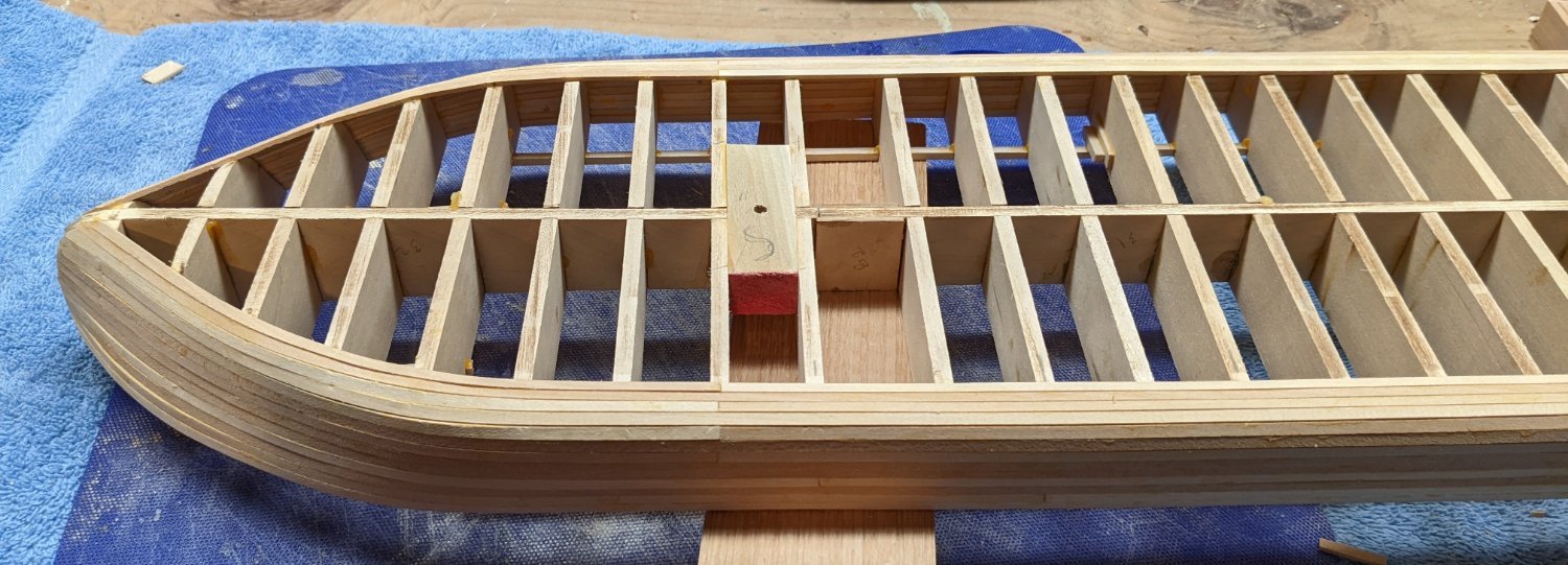
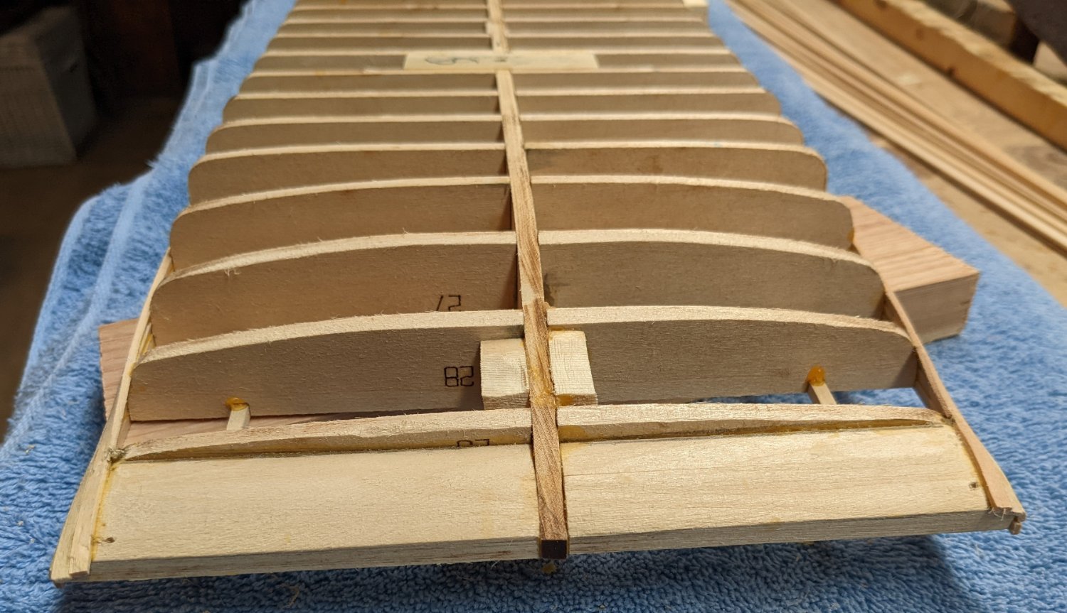
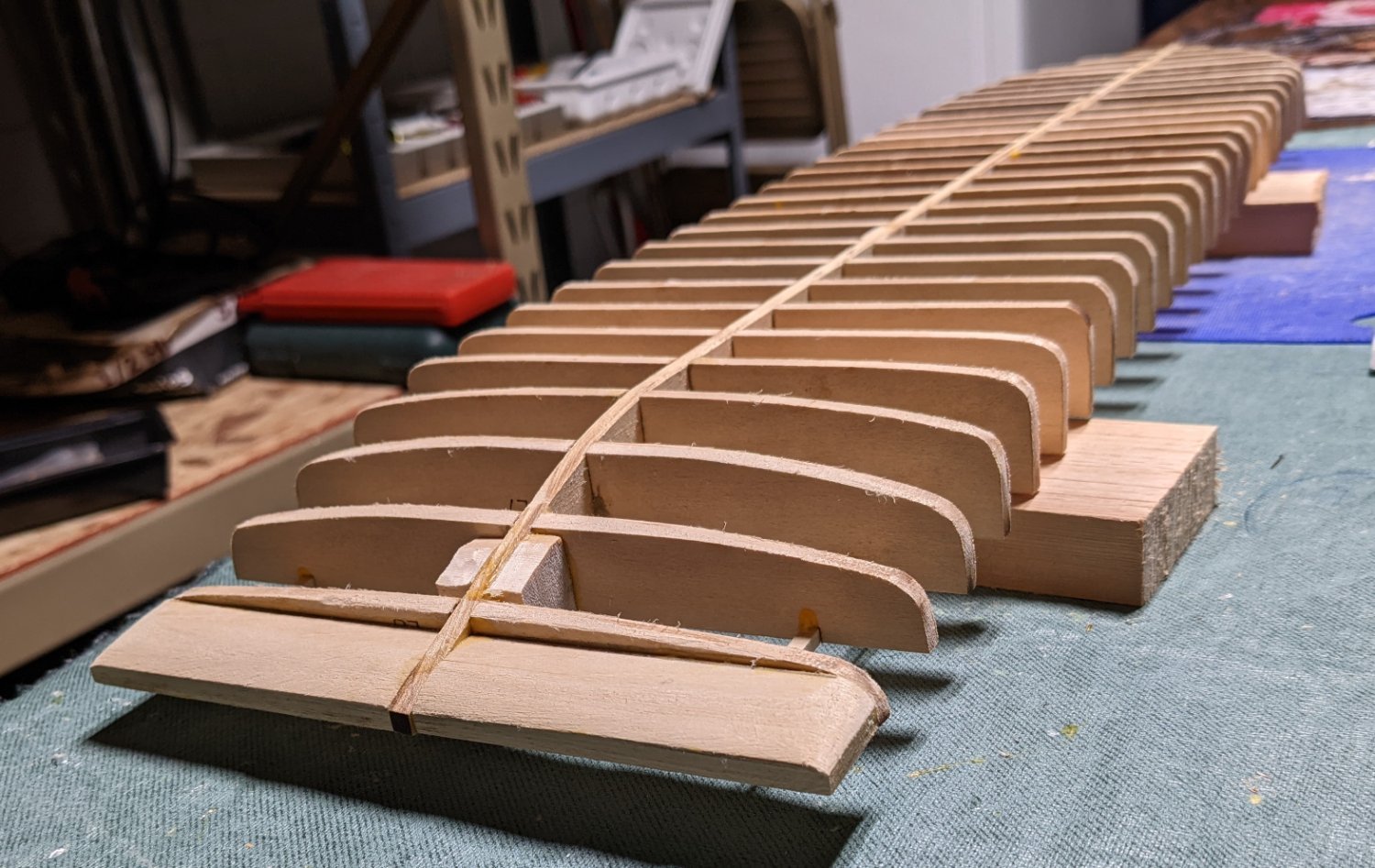
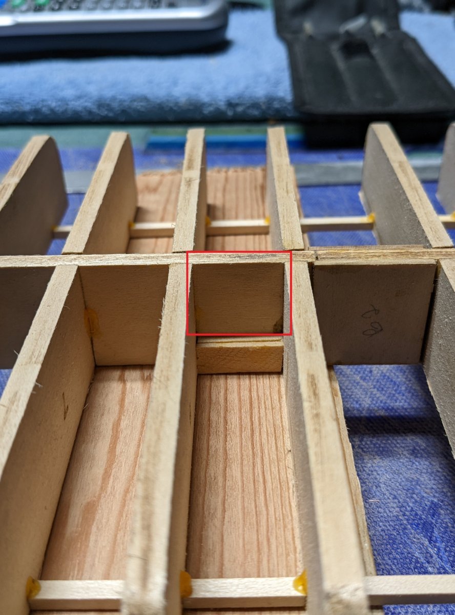
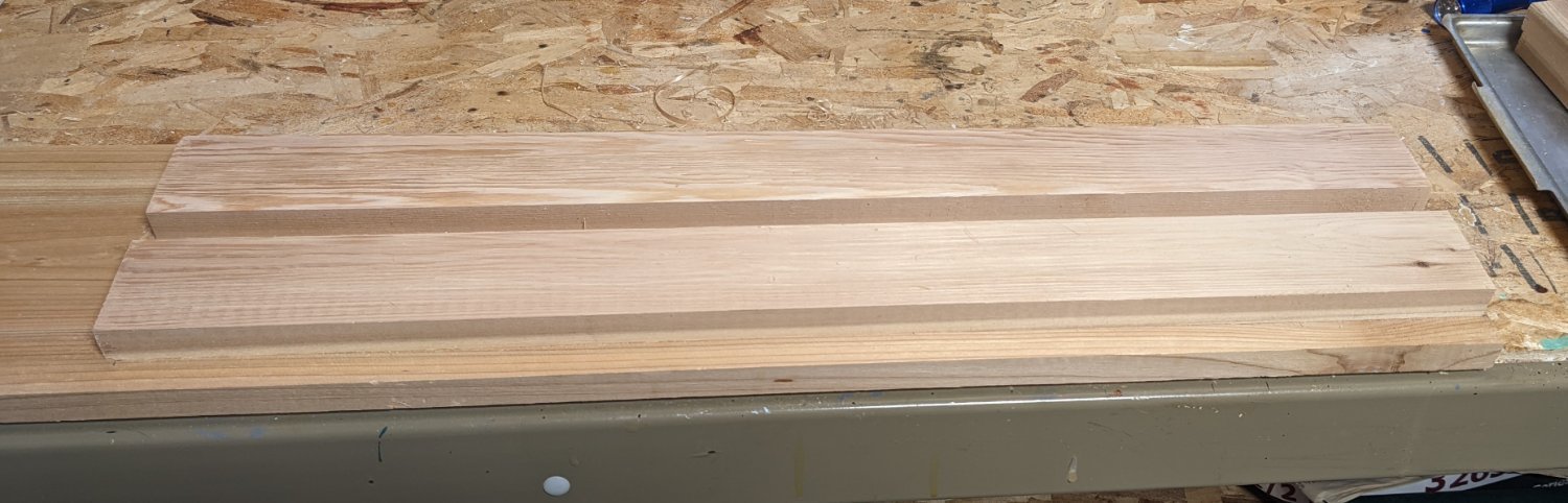
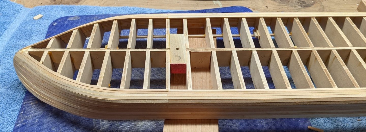
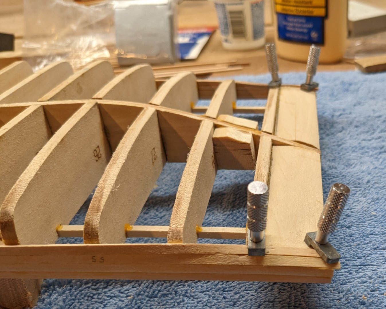
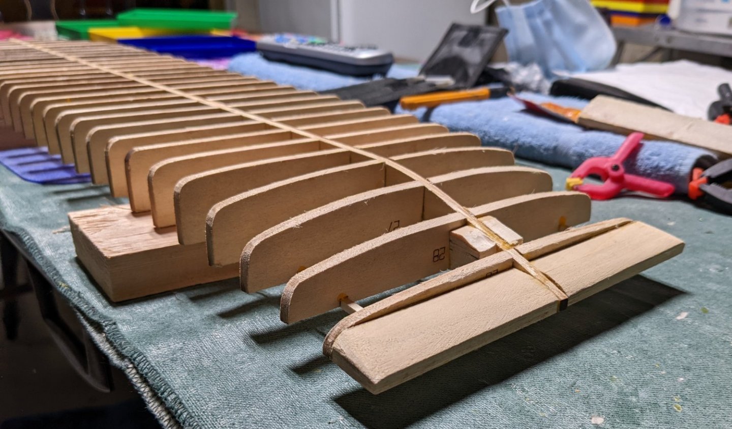
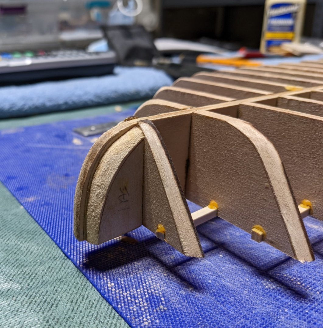
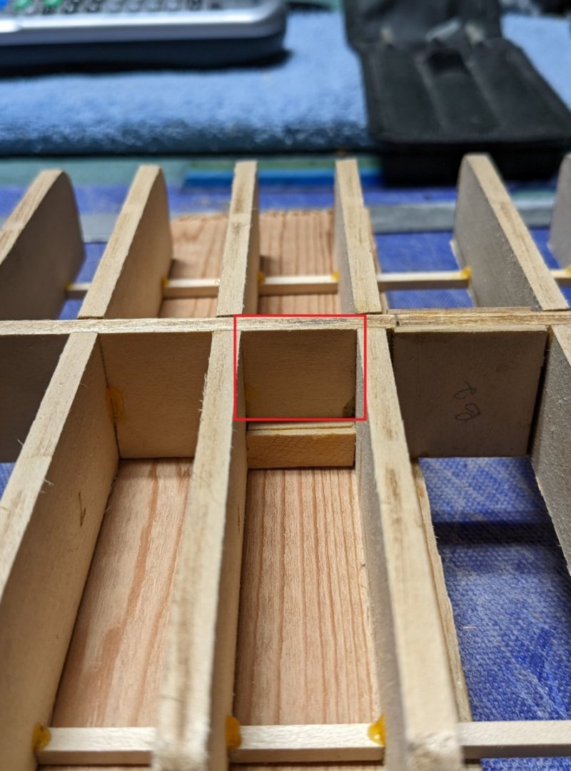
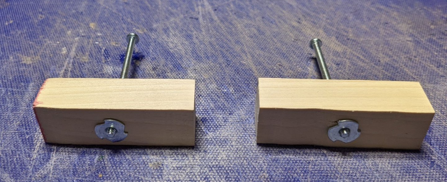
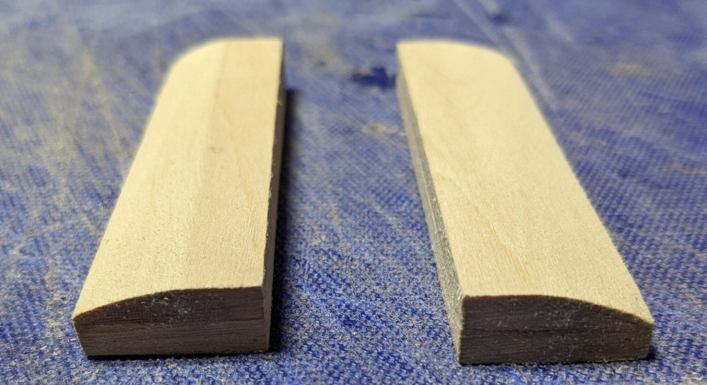
Cathead, Thanks for the information. I will check out yours and Brian's latest builds. As I have said earlier, I am somewhat new to this so I have a lot to learn. It has been a few days since I last got a change to work on the ship. At this point I have completed fairing bow parts 1A P/S and bulkheads 1 through 5. The supplied etched lines on these part are pretty accurate. As trimming progresses be sure to verify the angle with a piece of planking to insure the planks will have a good gluing surface.. Also completed was the fairing of the stern parts 29A/B and 28A/B on both the starboard and port sides. As before this is pretty easily verified as you trim will a piece of planking. Box sections: Stern sections... In the pictures they look to be a bit cock-eyed... They are somewhat, but not as much as what is shown in the pictures. Earlier when I repaired the stern section, I thought I had it square, but somehow in the clamping process a little bit of tilt came on. I have dry fitted the decks above and from what I can tell, the very slight tilt either goes away or is not noticable. Having said that, I may still try to dampen the last part of the keel and try to get it back to square. I have had issues on other models when the keel/bulkheads are not true. It is an error that can really keep coming back to bite you throughout the entire build if you are not careful. We'll see what happens. Now the part that really terrorizes me.... As others have done I decided to use a 3 prong Tee nut and bolt for the stand. As such it has to be done at this phase. Below show the two blocks made to insert between the bulkheads with the bolts. Main scary part of this process for me (at my still level) is cutting the two bulkheads where the blocks will be inserted. The part to be cut out is shown in red below. To strengthen the area a little bit before the cut I added a few strips of wood. Basically the bulkhead will be cut down to the added strips and the block inserted. Once the block is inserted and glued, the area will be far stronger than before, but during the cutting process, I easily could see me breaking what was left of the keel. Anyway, I had a lot of fear for nothing.... with a fine tooth saw and a little patience, I was able to pretty easily cut out the section of the keel and insert the block without breaking the keel. Below show the first block inserted and drying. Tomorrow I will take on the other block. As I do not have the final stand for the ship, with some scrap wood I will build a temporary stand to hold the hull while the decks are built. That is the beauty of the Tee nut and bolt - easy access to take the ship on or off the stand. Below will be the temporary stand for construction. Basically one 1"x8" board on the bottom and two 1"x3" boards on top leaving a slot in the middle for the keel. Bottom board is a little longer than the top boards to allow for construction of the paddle wheels at the stern. I have drilled the holes and verified the ship will sit properly in the stand. Ship will not be actually bolted to the stand until after the hull is planked.


- 158 replies
-
- 5
-
-
- chaperon
- Model Shipways
- (and 1 more)
-
Cathead, Thanks for the explanation on the supporting beams. I appreciate you comments and pictures. And I really like the looks of your Arabia. It is going to be a neat model. john
- 158 replies
-
- 2
-
-
- chaperon
- Model Shipways
- (and 1 more)
-
Brian, Thanks for the confirmation on the rub rail and lack of backing.... As for breakage, I always seem to find the weakest points in every model the hard way... Thanks for the word of caution on the deck extensions. However, but even with that caution, I have a feeling I will be getting a first hand knowledge as to how weak they are. 🙂 I might look into, in addition to epoxying, maybe also pinning them. We'll see at the time what thing look like. john
- 158 replies
-
- 2
-
-
- chaperon
- Model Shipways
- (and 1 more)
-
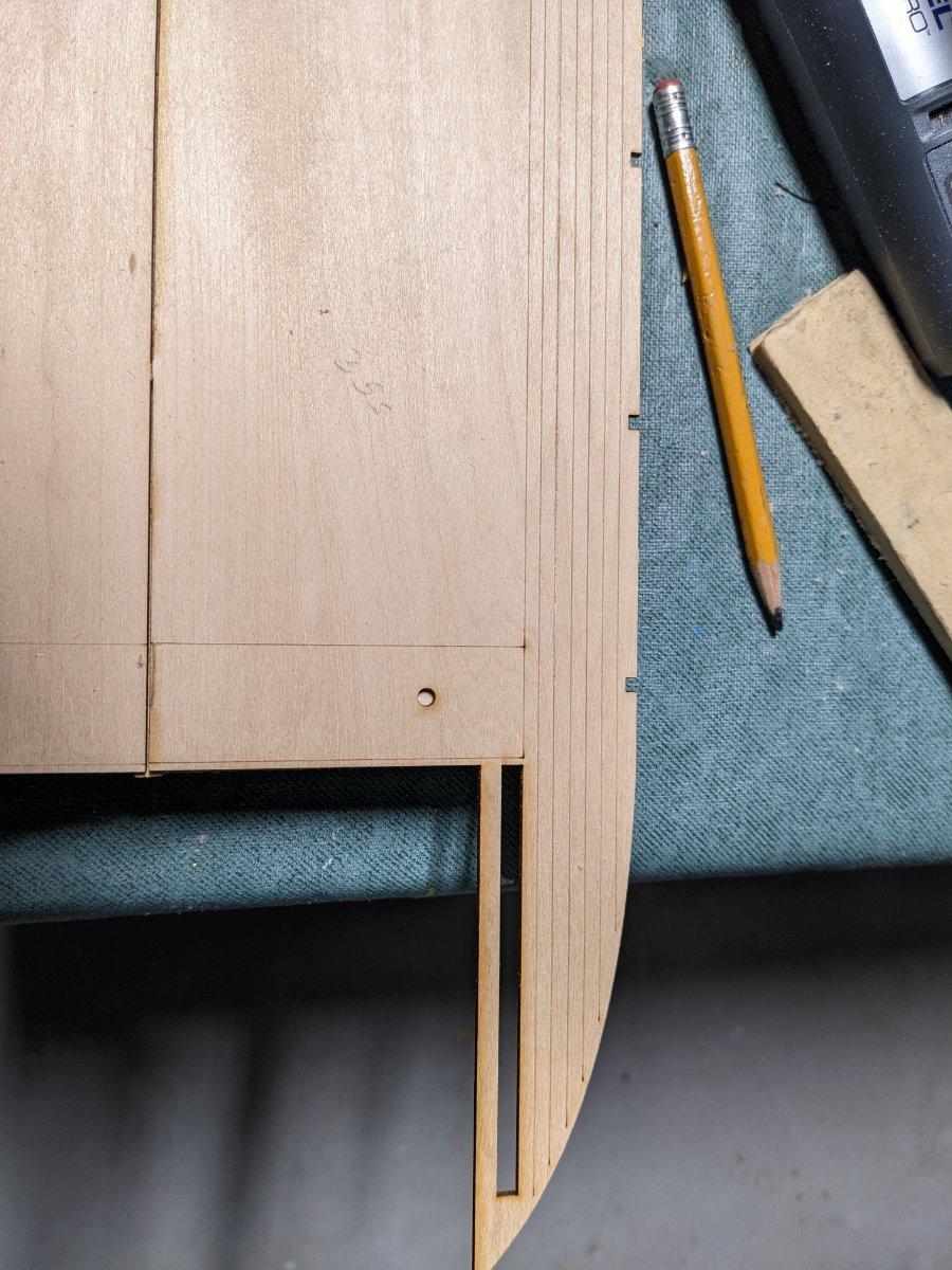
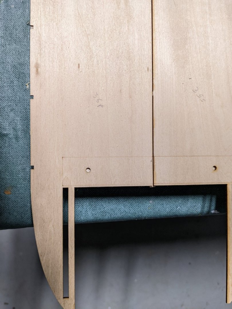
One additional comment for those who later are interested in building this model. Below is an extract of one of the above pictures. I would like to point out that in addition to the missing lines on one of the deck pieces, the pieces that are actually lined are very faint. In the extract below, the lines more toward the center of the hull are OK, but as the lines go out to the side they get fainter. I may be wrong, but to me if I was to prime and paint the deck, those lines would completely fill in and not show at all. This is also true for some of the etched line on structure walls. I will show those wall later on when I get to that stage. I had an outside conversation with MBP521 and he indicated that for the structure walls that were to show the etched lines, he had to go over them with an scriber tool " to increase the depth of each line prior to painting. Sound like that painful process is in my future for the walls I plan on painting and want the etched line to show. - Ugh
- 158 replies
-
- 3
-
-
- chaperon
- Model Shipways
- (and 1 more)
-
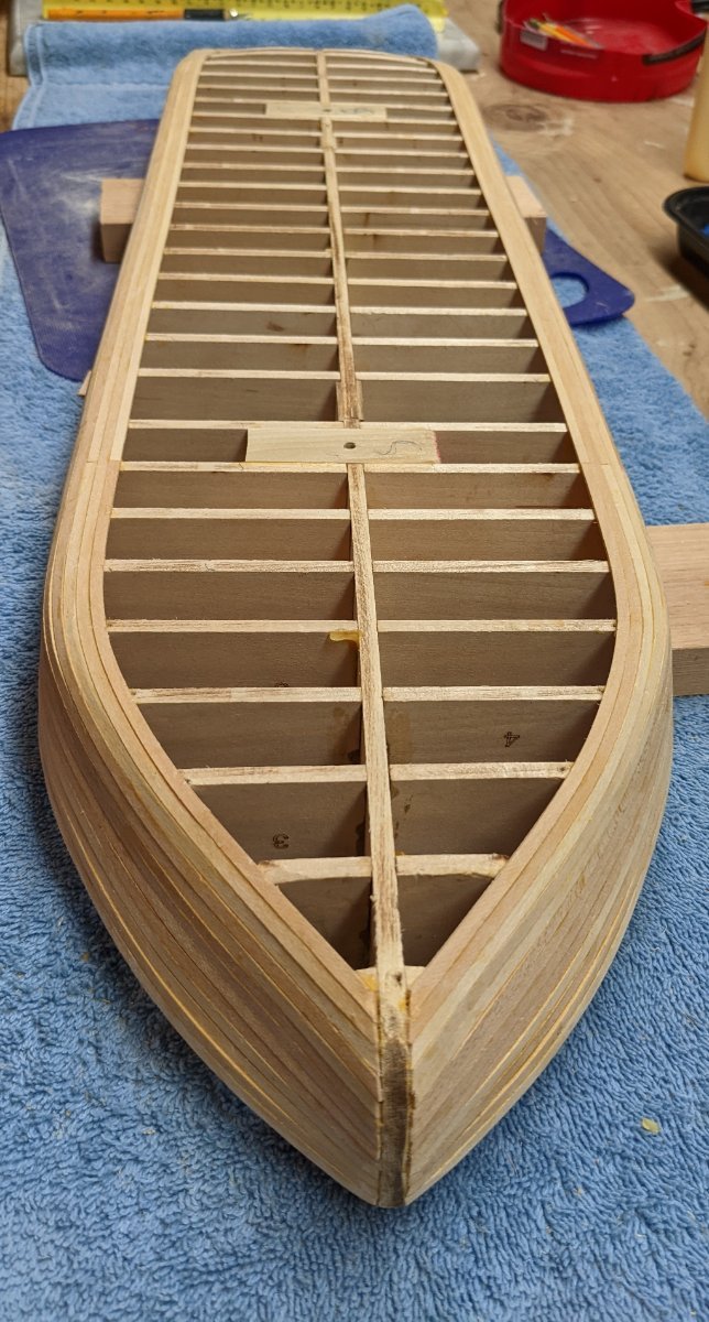
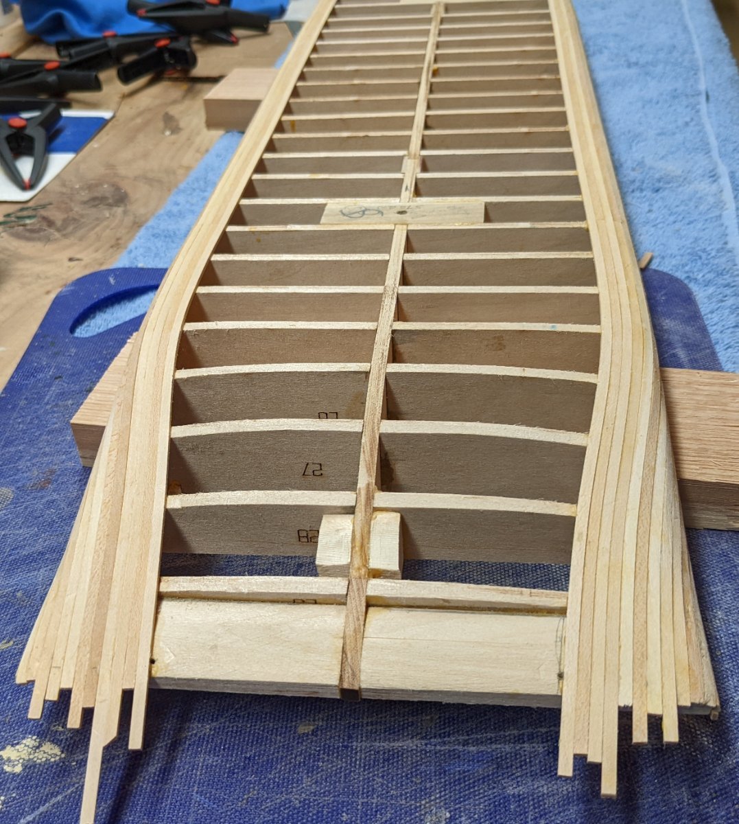
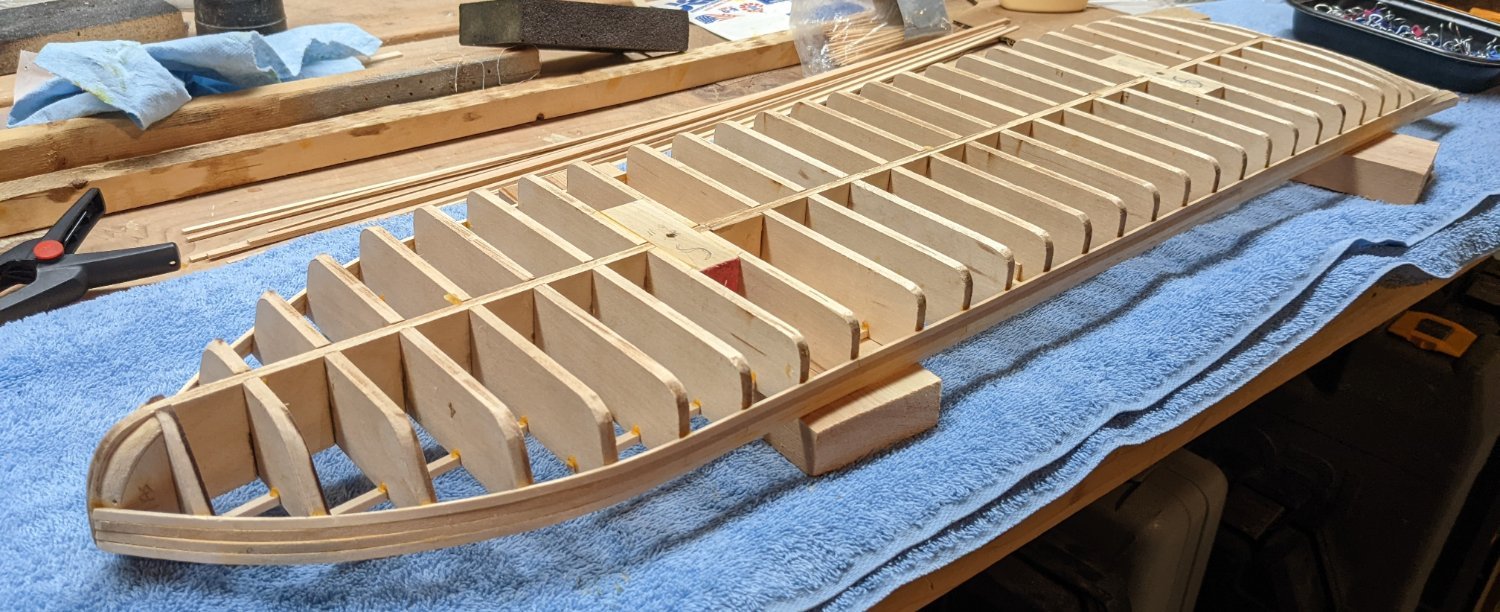
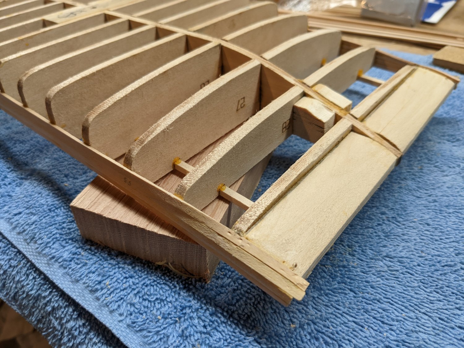
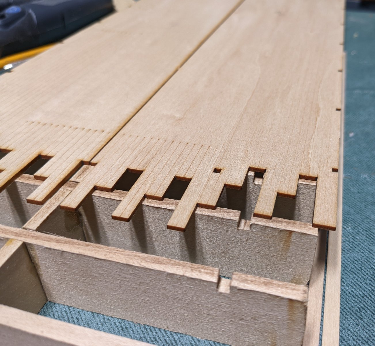
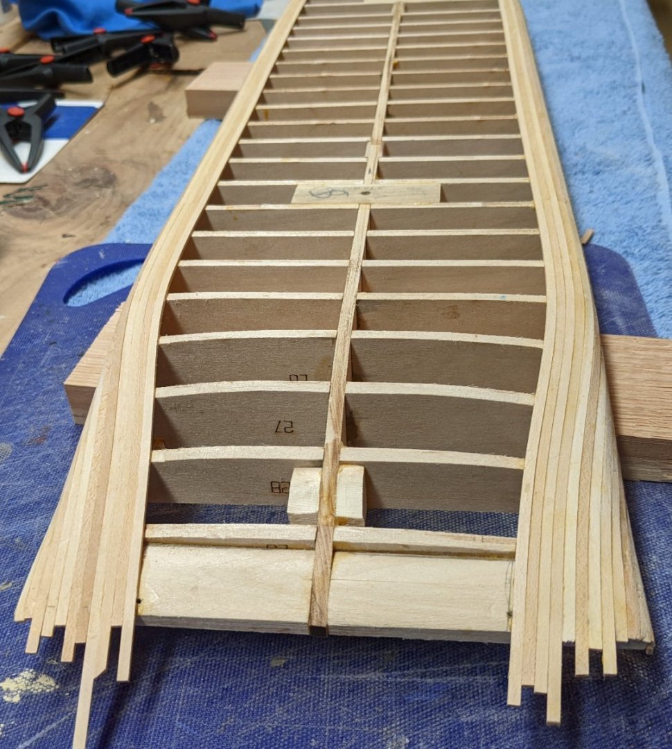
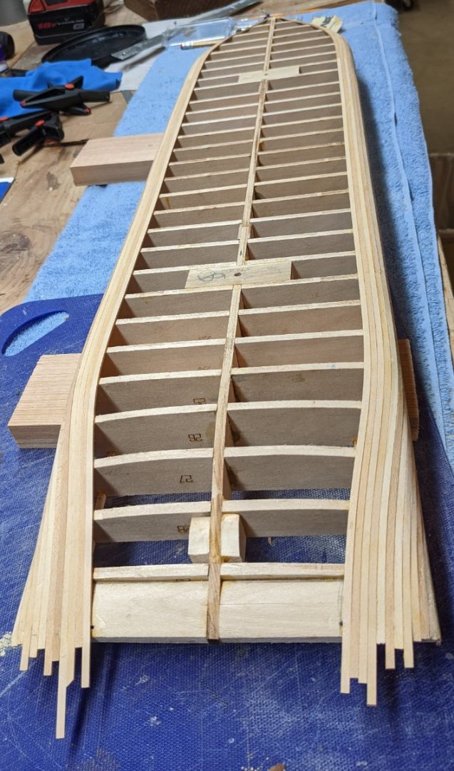
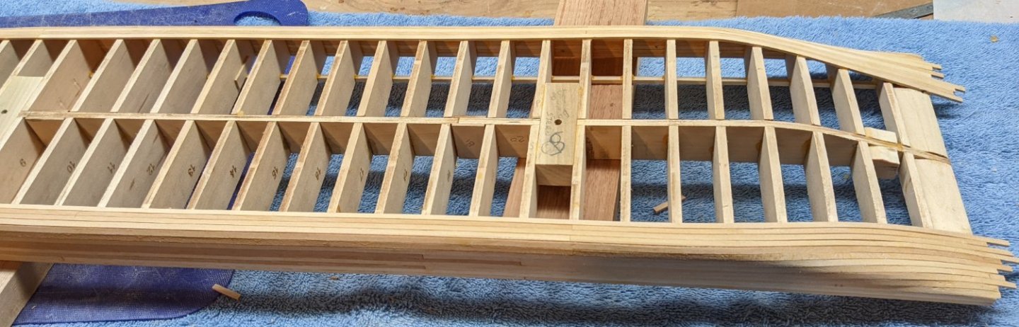
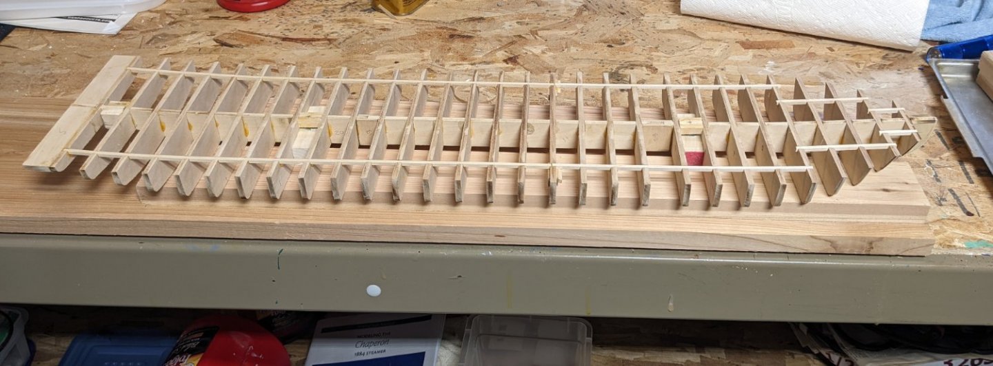
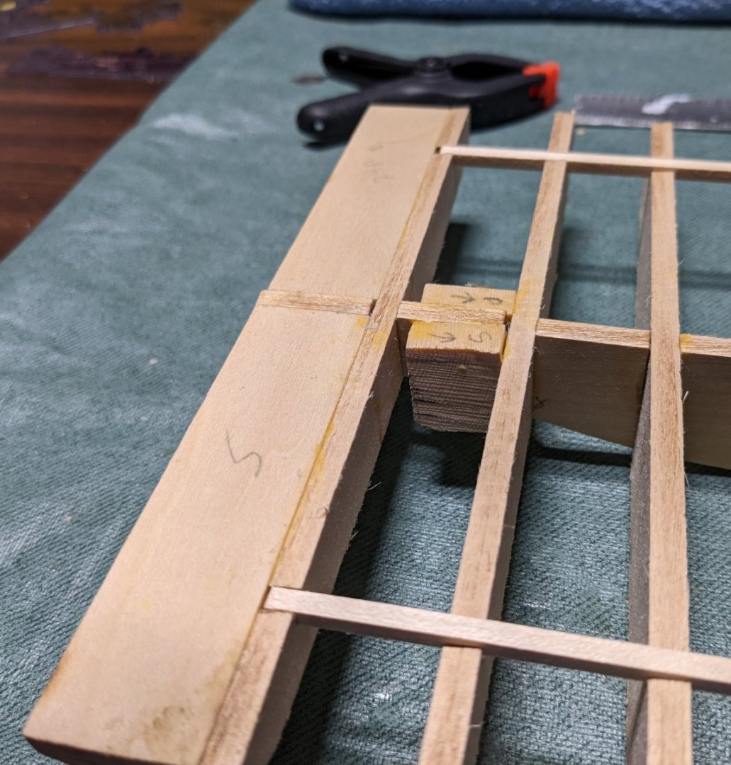
Planking finally complete. A slow process as I only glued a few bulkheads at a time - hoping to keep them straight. Be sure to insure all bulkheads are straight - Should be a consistent 13/16" between bulkheads. Next step is to carve stern parts (28/29A/B) and bow parts 1A/B and glue them in. Below are parts 28/29A/B and ready to be glued to bulkhead 29. Starting about bulkhead 27 the keel starts go up and gets much thinner between bulkheads 28 and 28. When gluing 28/29A/B to bulkhead 29 be very careful when clamping the parts to the bulkhead and keel. It is a very weak area.. Ask me how I know this 🙂 You guessed it,,,,, the keel between bulkheads 28 and 29 broke off. I do not have a picture of the breakage, but below shows my repair. In my panic I over compensated and decided I wanted a block (patch) that would be glued to both the Keel and bulkhead 28. In reality you only really need maybe a 1/16" piece of wood on both sides of the keel between bulkheads 28 and 29. In fact, I would suggest you do reinforce that area before you glue on parts 28/29A/B. Below is patch after drying. It still has to be trimmed, but it will be totally unnoticeable when covered with planking and decking Up until this point (if you ignore the breakage) the build has gone very smoothly. Bulkheads fit easily into the keel parts. But now it starts to get (shall we say) "interesting". I started laying out the deck pieces onto the hull just to see what we have going... Two issues have popped up. First issue is more of a Model Shipways issue. The four deck pieces should all have etched lines on them simulating planking. As you can see from the picture below, the port stern section (35P) has no etched lines. Even though I plan to plank the Main and Boiler decks, you need the etched lines to show where the structures are to be placed. Below shows part 35P with missing etched lines. In contrast it's partner part (35S) has the etched lines Model shipways is very good about replacing missing/broken parts. I sent them a note today and I expect the replaced part to be within a week. This is not really an issue. Looking ahead, the second issue is more of a question... There is a 1/16" x 1/4" rub rail that goes around the entire main deck. Problem is,,,, For most of the hull, the Main deck extends beyond the bulkheads by 3/8". And in the bow and stern sections the deck extend much more beyond the bulkheads. I guess my question is, is this 1/16" x 1/4" rub rail only attached to the edge of the main decking and just hangs down in the air? Seems like that is not much gluing area and a rub rail should have some sort of backing. I could always put some additional wood behind the rub rail but I figured I would ask the question of those who have built Chaperon before. Is the rub rail really only glued to the 1/16" main deck edge? Here are a couple shots of the deck pieces at the middle of the hull. The 1/16" planking on each side of the hull will take up 1/8" but that still leaves a large gap and not much area to glue the rub rail.


- 158 replies
-
- 4
-
-
- chaperon
- Model Shipways
- (and 1 more)
-
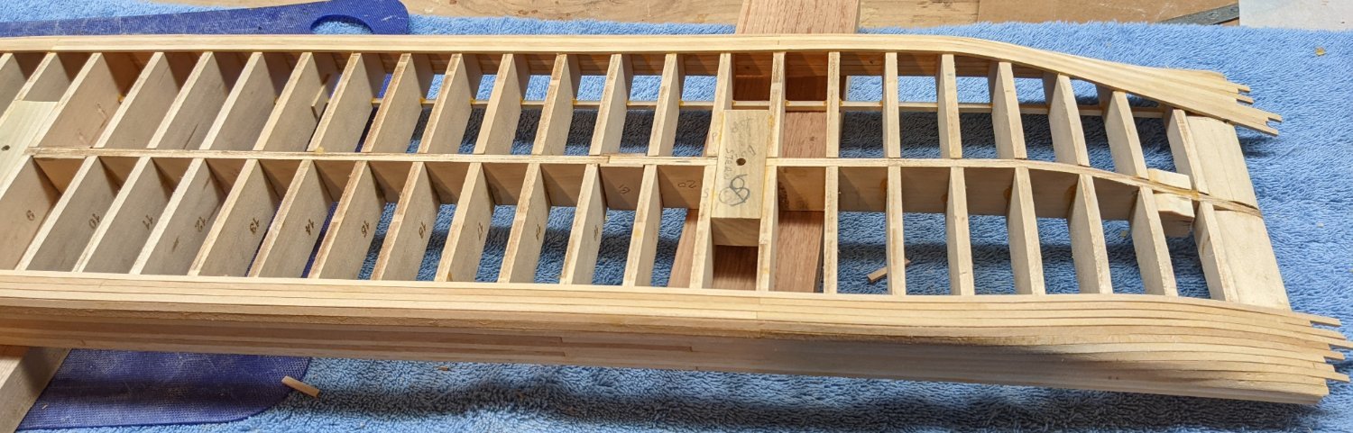
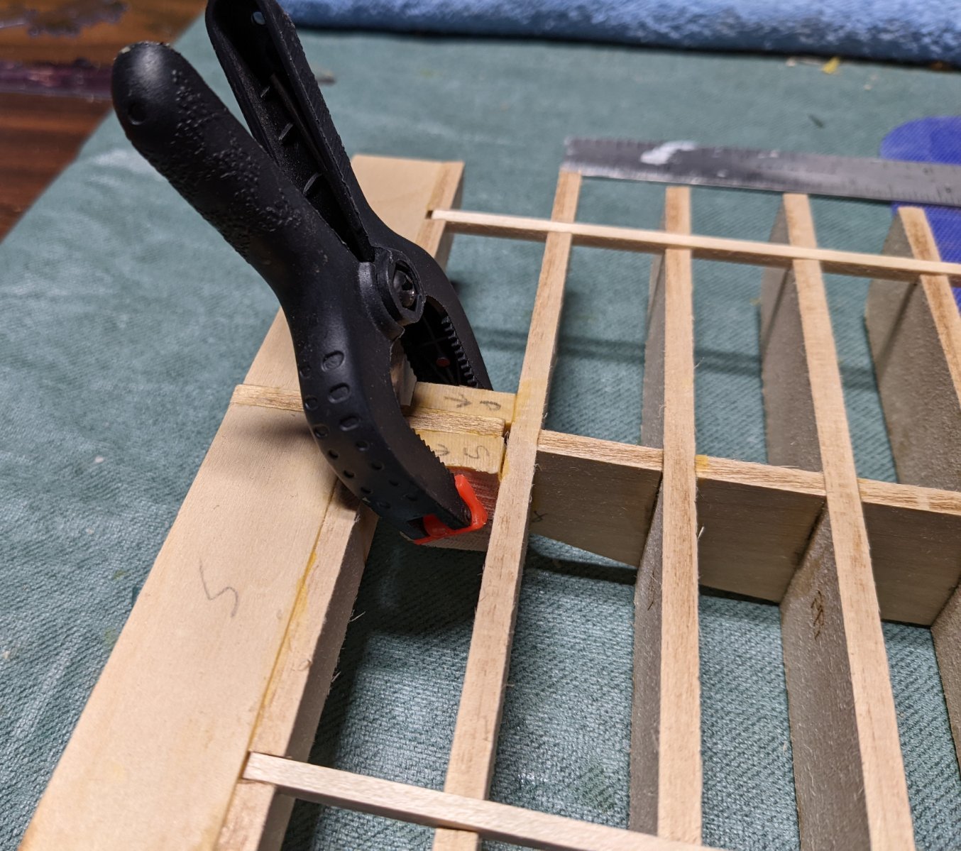
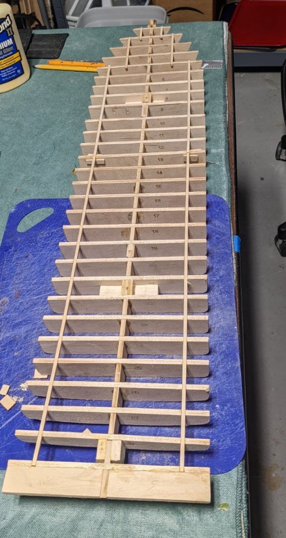
Gsdpic, Thanks for the comment. I appreciate it... But in this case it is an optical illusion. As I go I measure each bulkhead to insure each one is exactly 13/16 apart. In addition I have a triangular ruler that I put in the slots to insure all is straight. I have been down that road before with uneven bulkheads. If they are not exact you will keep paying for that mistake over and over again throughout the build. It keeps coming back to cause problems. Do not hesitate to question anything you see in this build. I am sure you will see errors that hopefully I can correct before it is to late. Here is a picture of my ruler in the slots as a triple check of the alignment.
- 158 replies
-
- 6
-
-
- chaperon
- Model Shipways
- (and 1 more)
-
Yvevidal, Welcome aboard.... Glad to have to follow along. A few more bulkheads installed - 10 out of 29 so about 1/3 the way home. I have to say these bulkhead fit very nicely into the keel. There is a little slop in the connection so you will need some sort of square to keep the bulkheads straight. A little slop is easily accounted for with a metal square and a whole lot easier than having to file each bulkhead in order for it to fit into the keel. In my case I used an angle plate to insure the bulkhead was square to the keel, but that is probably overkill. Any square block will do the trick. I have even seen some folks use the lego blocks or metal corner braces.. they are cheap and very square edges..

- 158 replies
-
- 7
-
-
- chaperon
- Model Shipways
- (and 1 more)
-
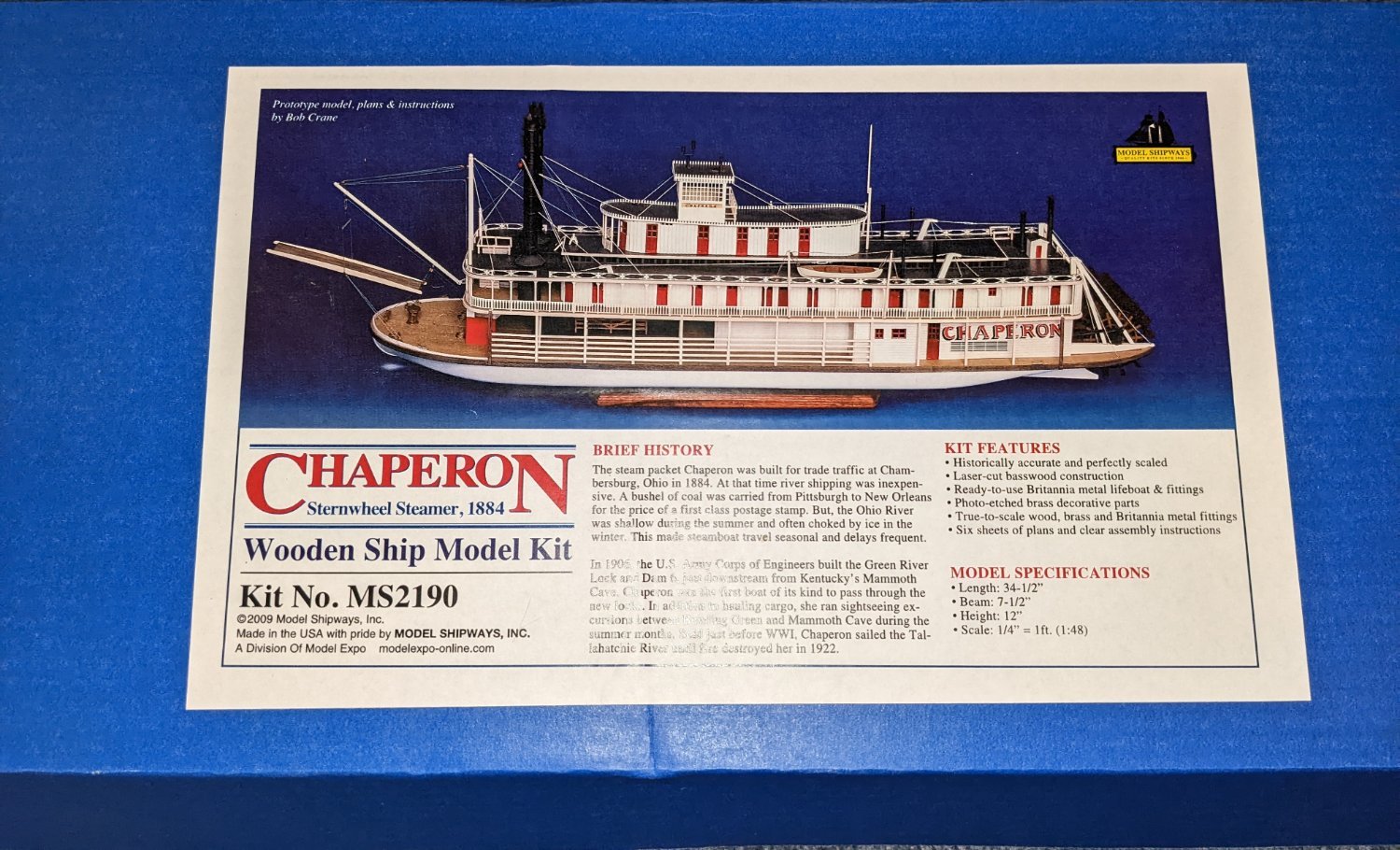
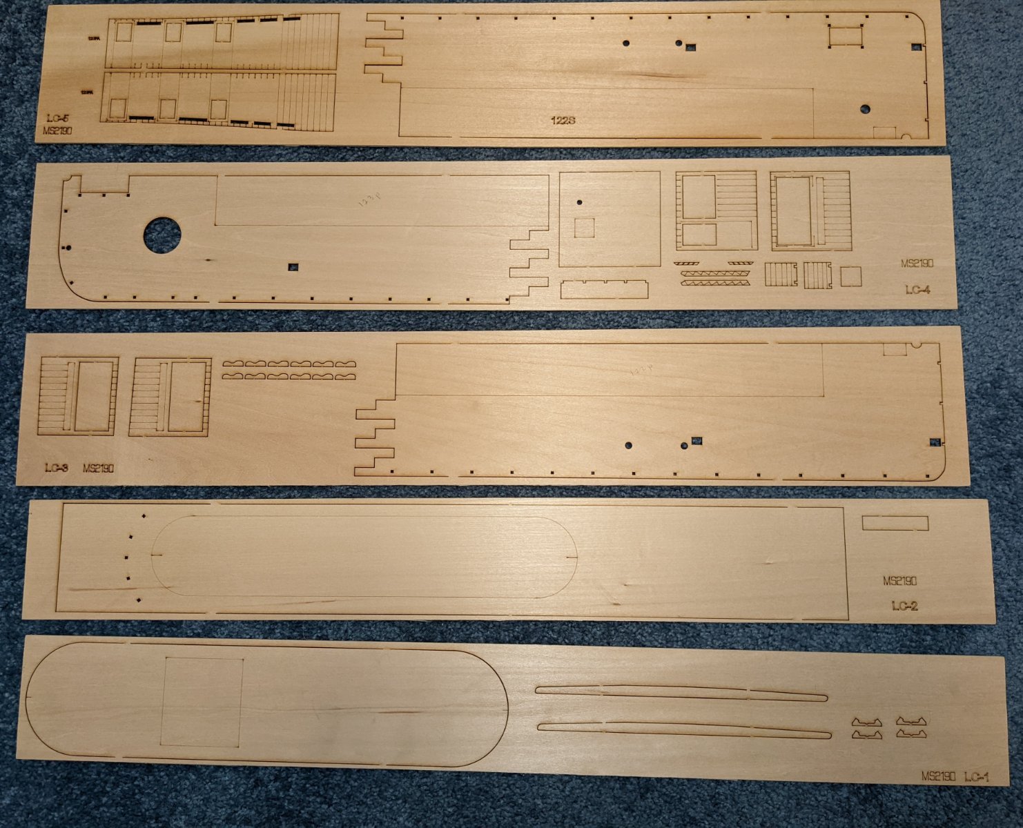
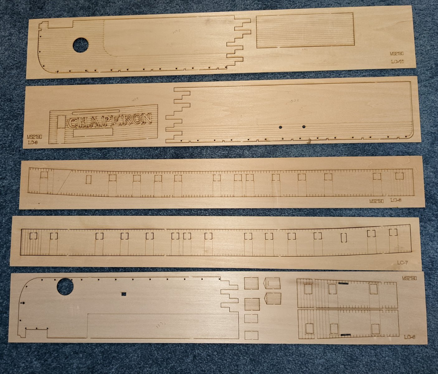
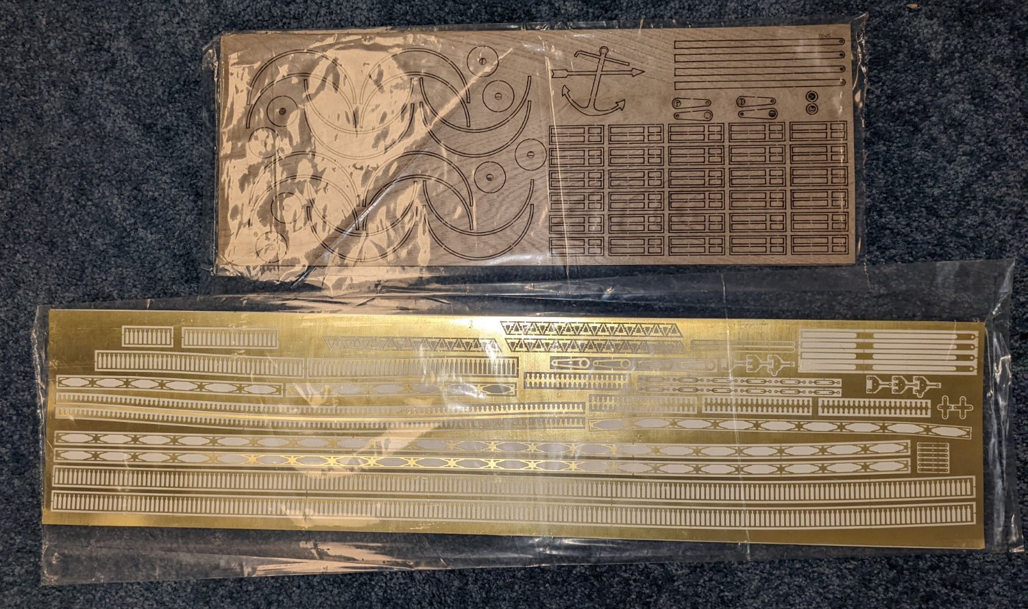
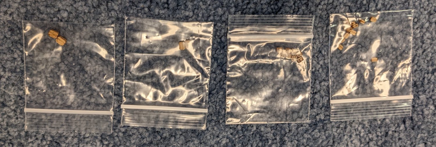
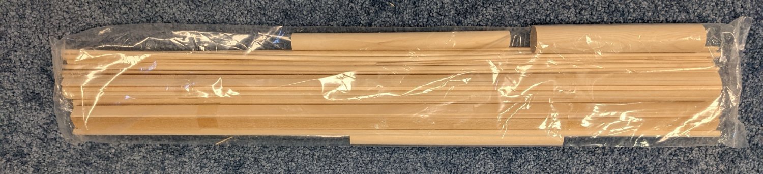
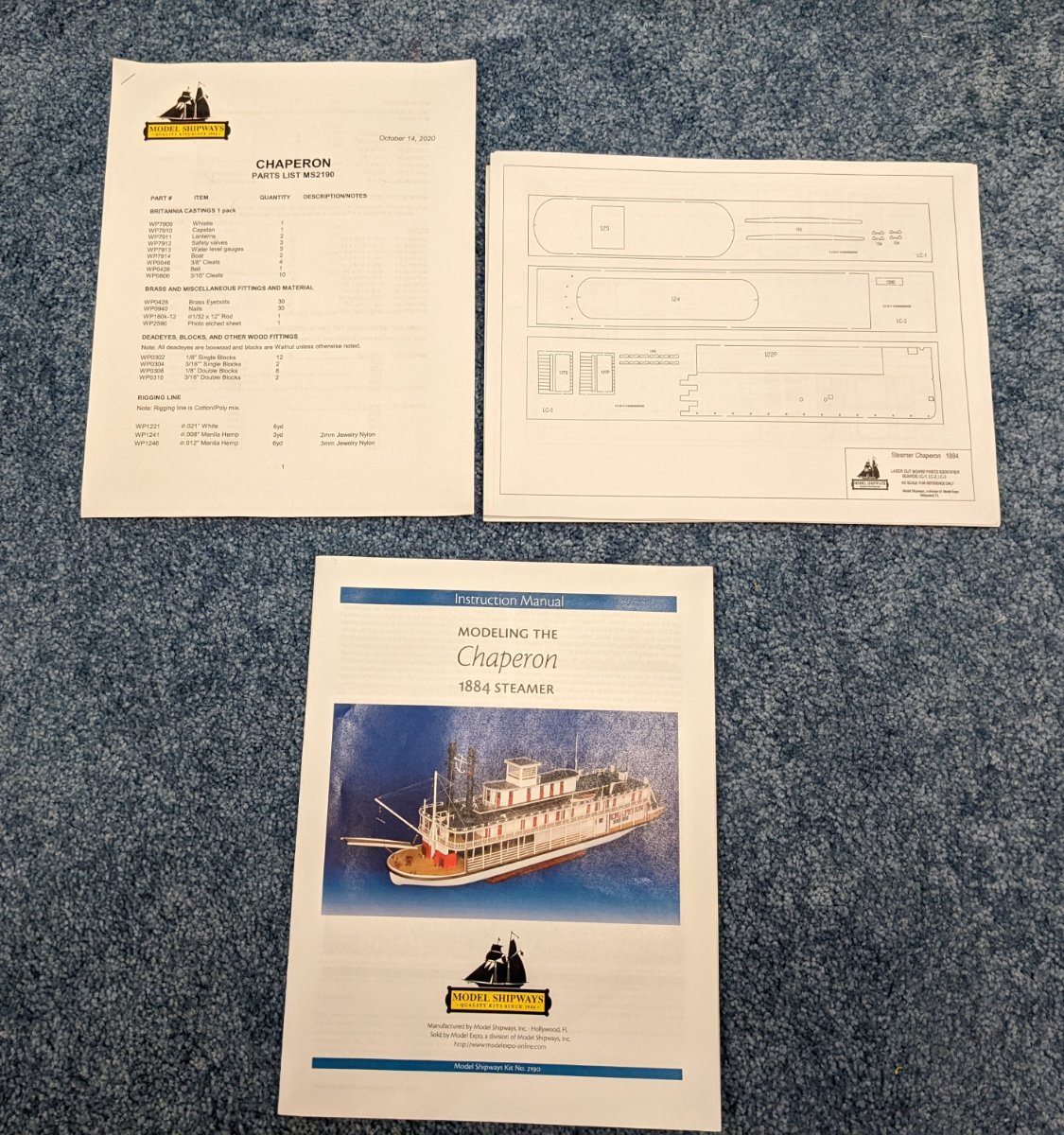
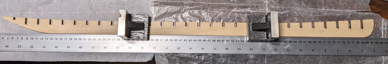
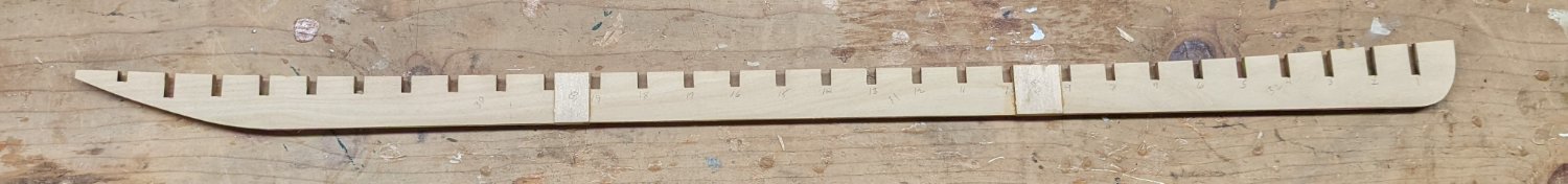
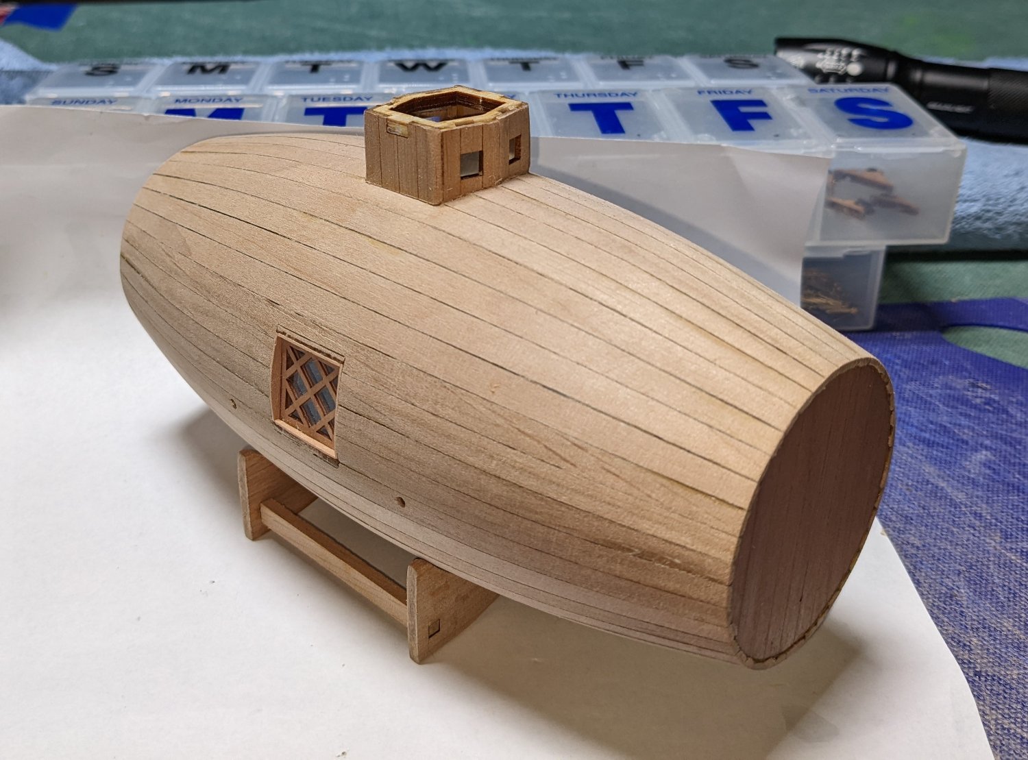
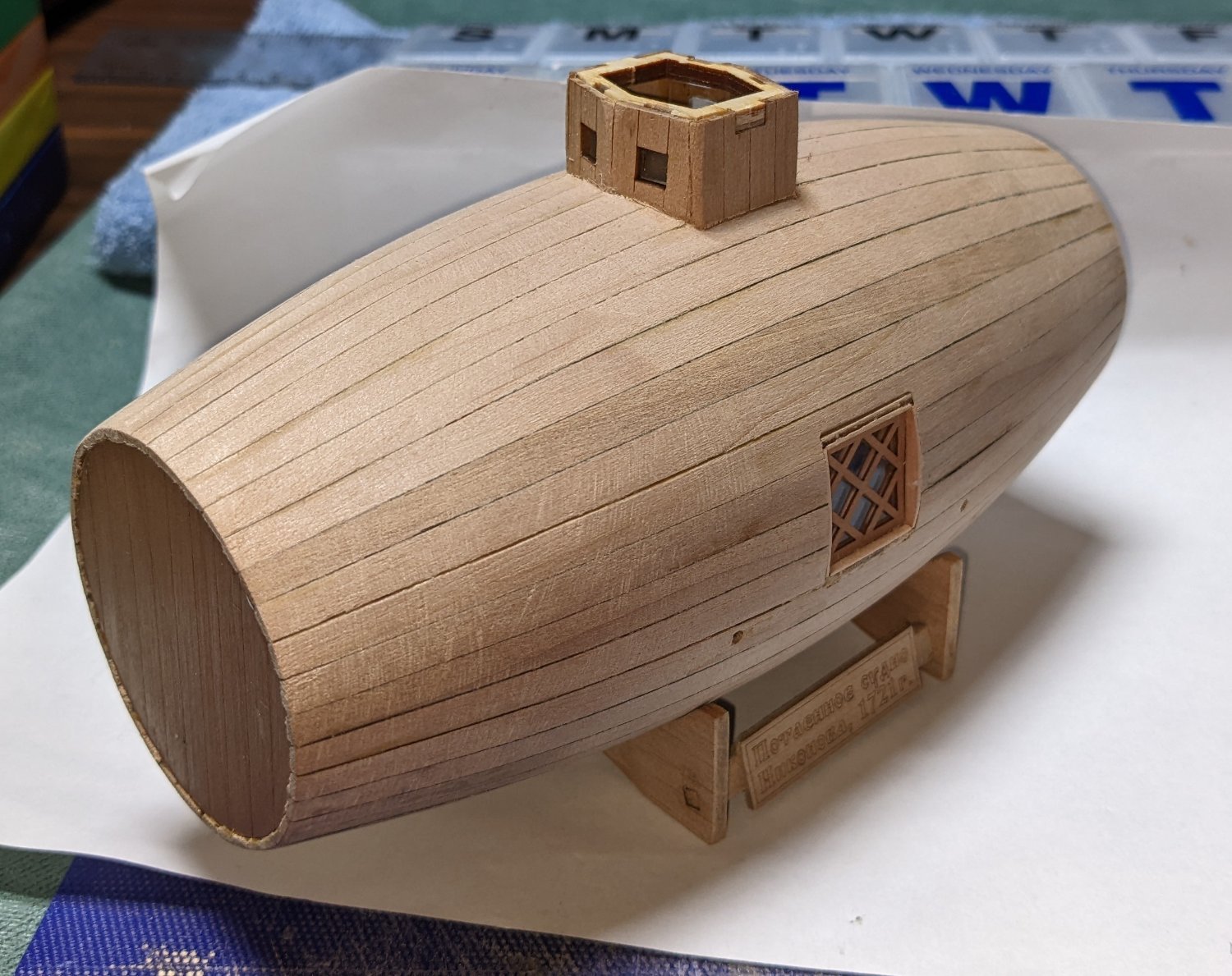
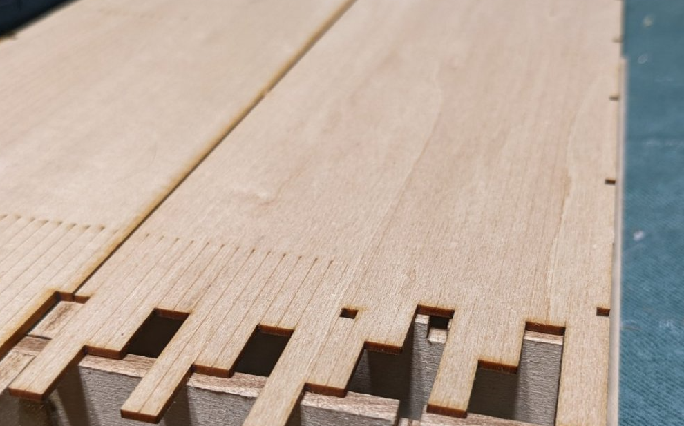
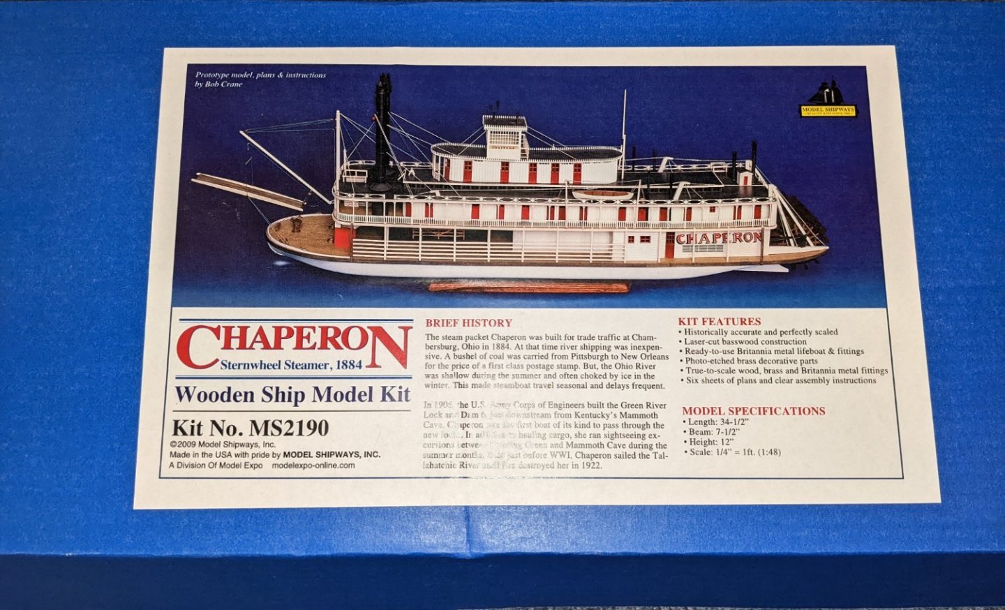
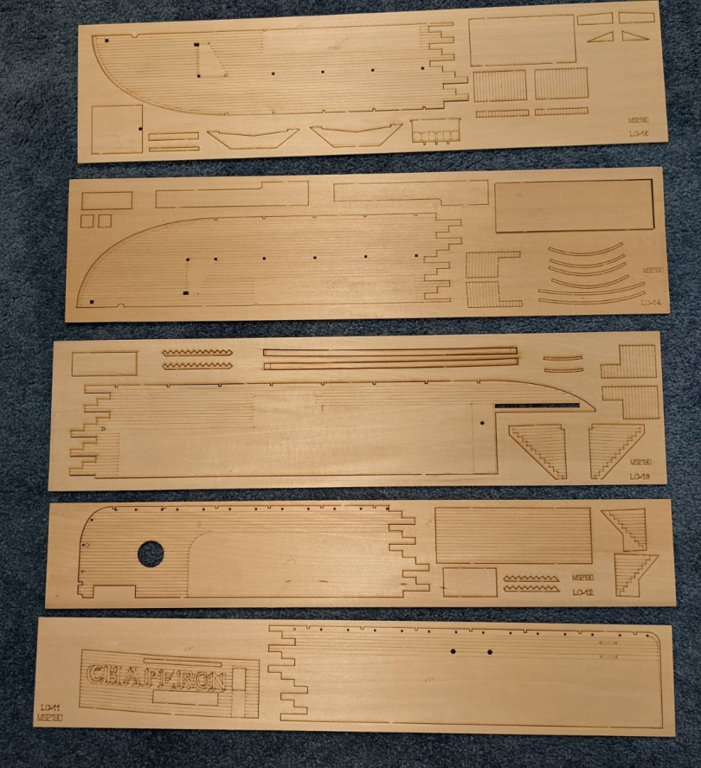
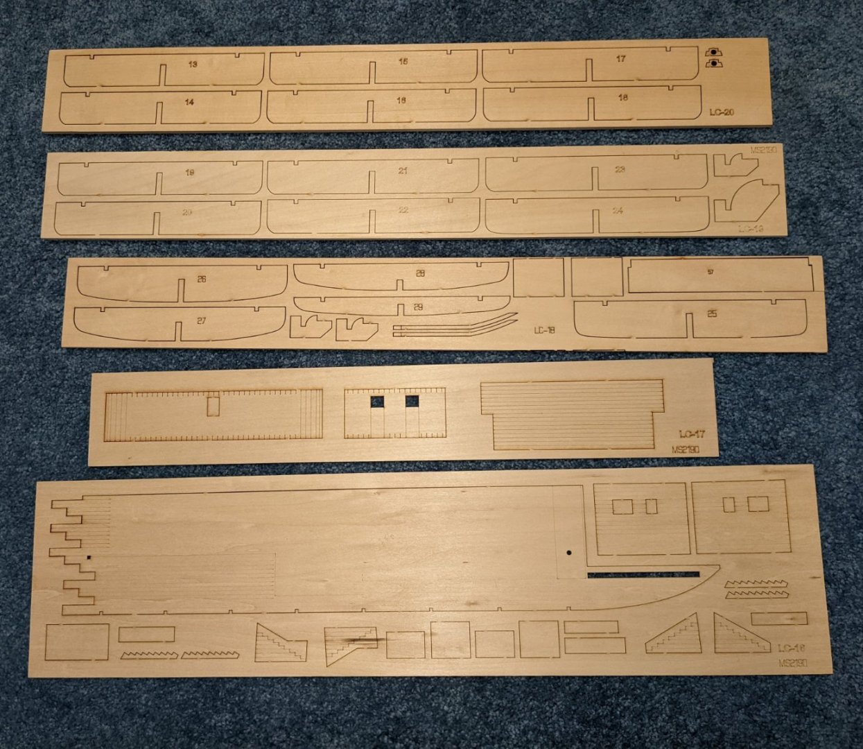
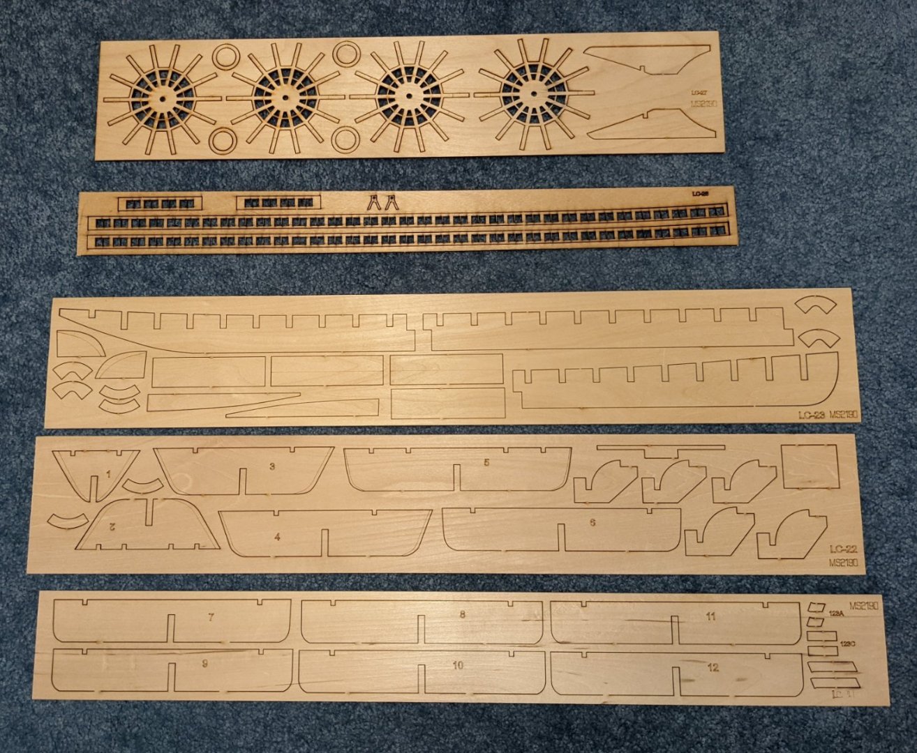
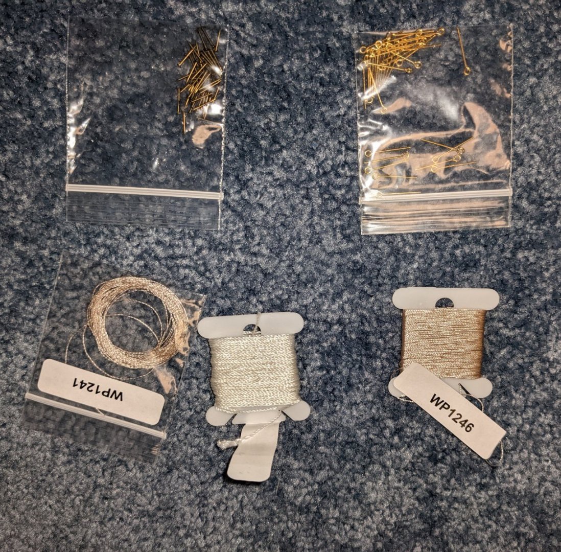
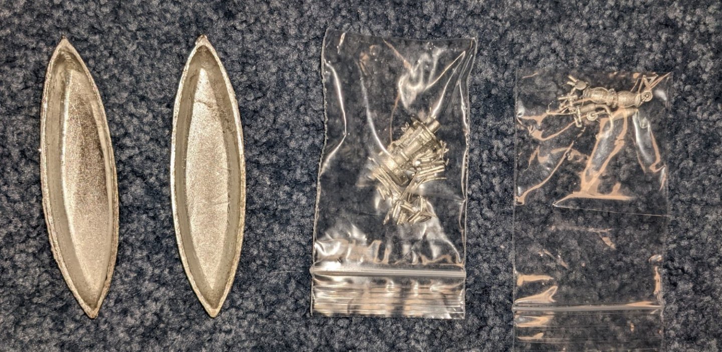
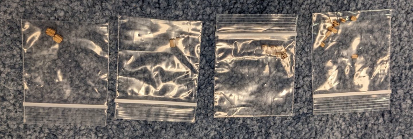
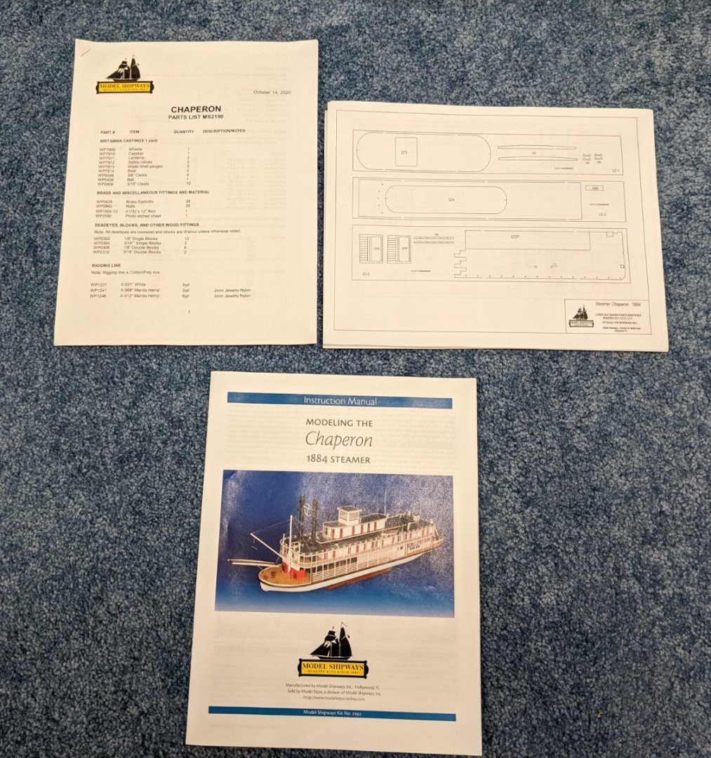
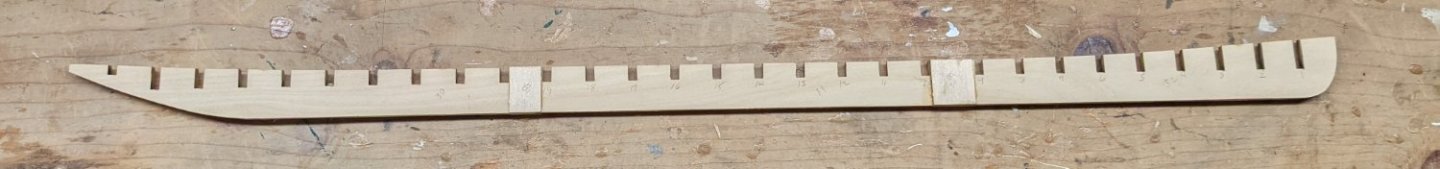
Just completed the Secret Vessel "Morel". What I call a "quick win" as it only took a couple months to complete. For those of you who have not seen the Morel model, I recommend you check it out. It is a quirky little model that is easy to build but looks really neat. And a definite break from the usual year long builds of most models. Anyway, Now it is time to put my "big boy pants on" and take on the Chaperon. I am by no means an expert builder - average at best, but as they say - the journey is the destination. And I do enjoy the journey ..... or the build in this case. I would like to say thanks to all who have built, and supplied excellent build logs, that have gone before me with the Chaperon model. There have been some excellent Chaperon builds - I would say museum quality. I will be shamelessly borrowing (stealing) some of the best ideas from those logs as I build my model. I am still too new at building models to have many original ideas of my own. My build will by no means compare to those who have gone before me, but I will have fun. With that in mind I will start right in with the unboxing.... Most people can just skip over this section unless you really are interested in the box contents. There are 27 sheets of laser cut basswood. Note on this sheet and others some of the boards have lines etched in them... With this model they are to simulate planking. Not sure if my model is odd or not, but to me those lines seem very thin (faint). They look like after a coat of primer and paint they would be completely filled in. We will see what happens when I get to that stage, but right off the bat this model may get (shall we say) "interesting". Included with the last laser cut sheet is one large photo-etched brass sheet. pins, eyelets, and some nylon line..... Will probably not use this line as it seems to be pretty cheap. A couple of britannia life boats and assortment of other britannia parts. An assortment of single and double wooden blocks An assortment of wood strips and dowel rods for the build Inventory list of all included parts A 12 page manual with a brief history of the Chaperon and the build instructions. 12 sheets identifying each item on the laser cut wood pieces and photo-etched brass sheet. Not shown, but included are 5 large plan sheets depicting the various stages of the build On to the build.... As with most builds that are larger than the wood sheets, we start by gluing the keel made up of three 3/16 pieces. The joints between the three pieces (under the weights) are reinforced with small reinforcement pieces (B1 & B2). The ruler was used to help keep the keel straight. As you can see, this is going to be a big ship. With the glue dry and the weights removed you can see the reinforcement pieces (B1 & B2). There are a pair of them on each side of the keel. Each of the 29 bulkhead slots have been labeled to help keep track of the bulkheads as they are installed. As so we begin the process of laying the bulkheads. Be sure to remove all the laser charred marks on each bulkhead before installation to insure the glue gets a good grip on the wood. I mention this now and will not mention it again, but that goes for all the laser cut parts. Char marks need to be removed from each piece throughout the entire build. Instructions say to start with the middle bulkheads and work your way out to the bow and stern. This will take awhile as you need to insure each bulkhead is square and need to wait for the glue to dry before moving on to the next bulkhead. It is going to take a few days to get all 29 bulkhead installed.


- 158 replies
-
- 5
-
-
- chaperon
- Model Shipways
- (and 1 more)
-
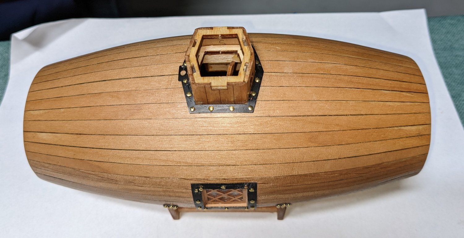
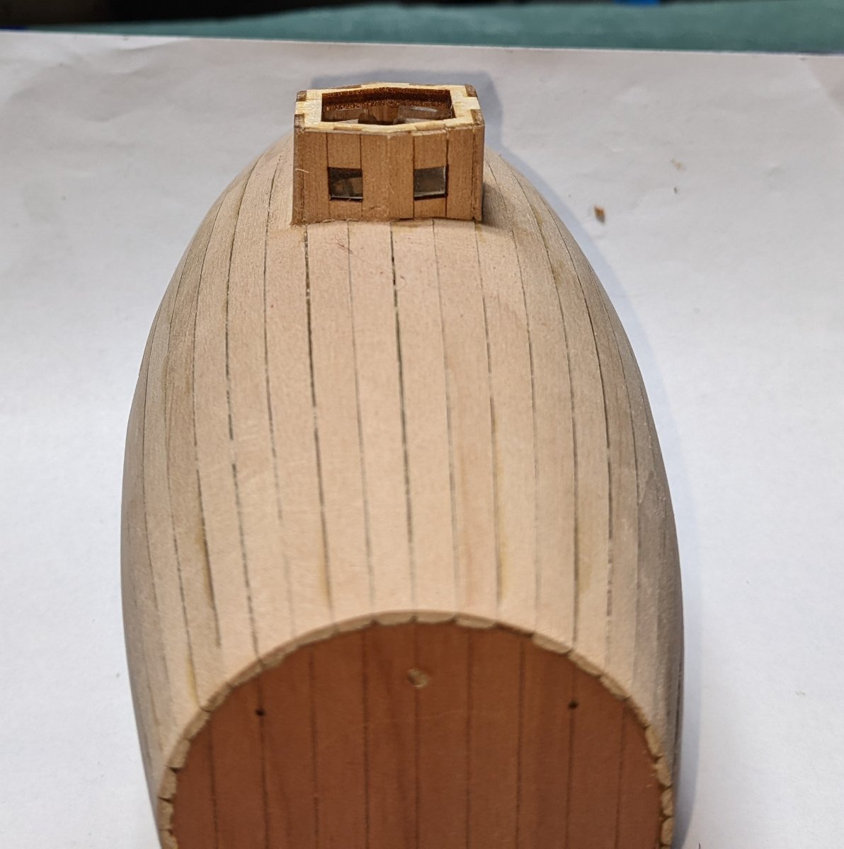
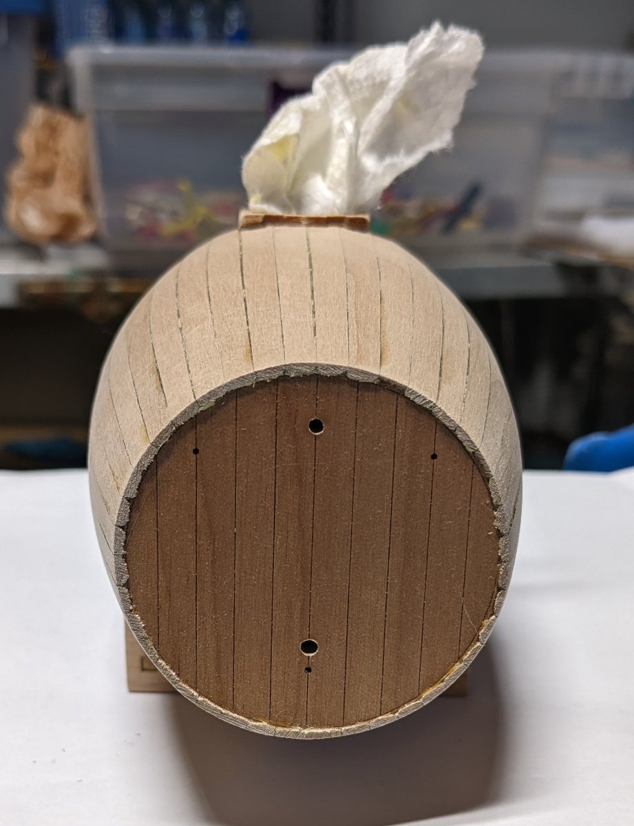
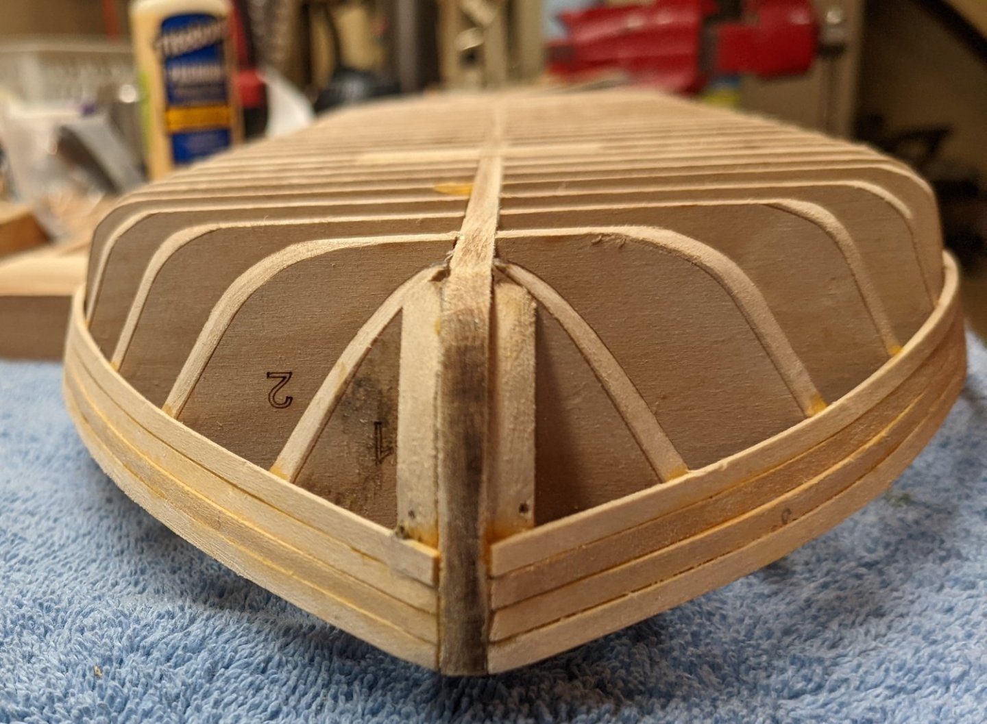
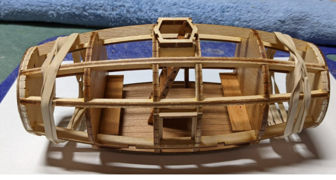
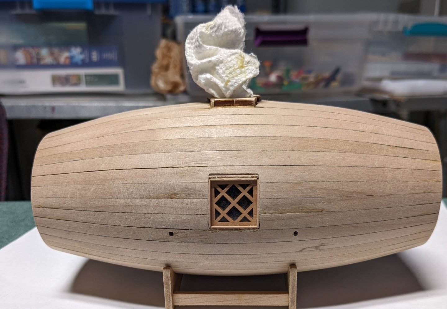
HardeeHarHar You bring up an interesting point as to whether there is enough room to add "stuff" to make it look interesting. Below is a shot I took early in the build showing what is inside. Inside you see two benches and a ladder. As is, not a lot of room to add stuff... However, if you decided to open it up, you would have to be creative and modify the benches to allow access to the bow and stern sections. In addition you would have to expand the floor sections to reach the box and stern. There is where the model is not very realistic as you see,,,, no access to bow and stern sections. Not shown here, but the final pictures show ballast weights that from inside are dropped when the ship wants to rise to the surface. Without access to the bow and stern sections, there is no way to release the ballast. So, if you open up the full ship allowing free access from bow to sterns, there is plenty of room to get creative with some flooring, small figures, buckets, stools etc.. Whether you open it up or not, this is a fun quirky model to build, looks good, and is a good break from some of the longer "marathon" builds. As I call it,.,,,,, a quick win.
- 36 replies
-
- 5
-
-
- Morel
- master korabel
- (and 1 more)
-
Robert952 I just used Minwax Wipe-on Poly - Clear Satin.. I mainly use it because it is applied with a rag instead of a brush as normal poly. As such the finish is really smooth with no runs. Also, even though it is listed as satin, as you can see there is still a slight shine to it. To me just enough. To me wipe-on poly is a great way to get a good smooth finish. But you have to use a number of coats as each coat is very thin. I think I have 5 coats on this model. I am not sure what wood is comes with the morel kit, but it's not basswood. It is some other type of slightly colored wood. As such for me no stain was required just applied the poly over the raw wood. The 5 coats of poly also darken it up slightly despite the fact that it is "clear satin". If you have not used a Wipe-on Poly you really need to try it. It works great. One more point,,,, I have not tried this but wipe-on poly is really just normally polyurethane thinned to about 1/2 strength. So if you already have some polyurethane and have some paint thinner or turpentine, you could make up yourself a small batch of "home grown" wipe-on poly and try it on a test sheet of wood. Just make sure that you only use paint thinner or turpentine if you have oil based polyurethane. If you have water base polyurethane you will need to thin that with a water based thinner.

- 36 replies
-
- 2
-

-
-
- Morel
- master korabel
- (and 1 more)
-
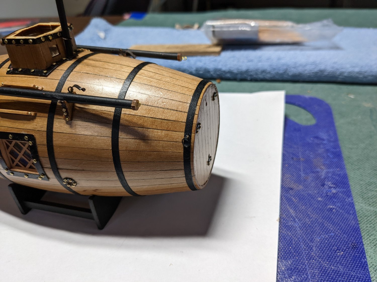
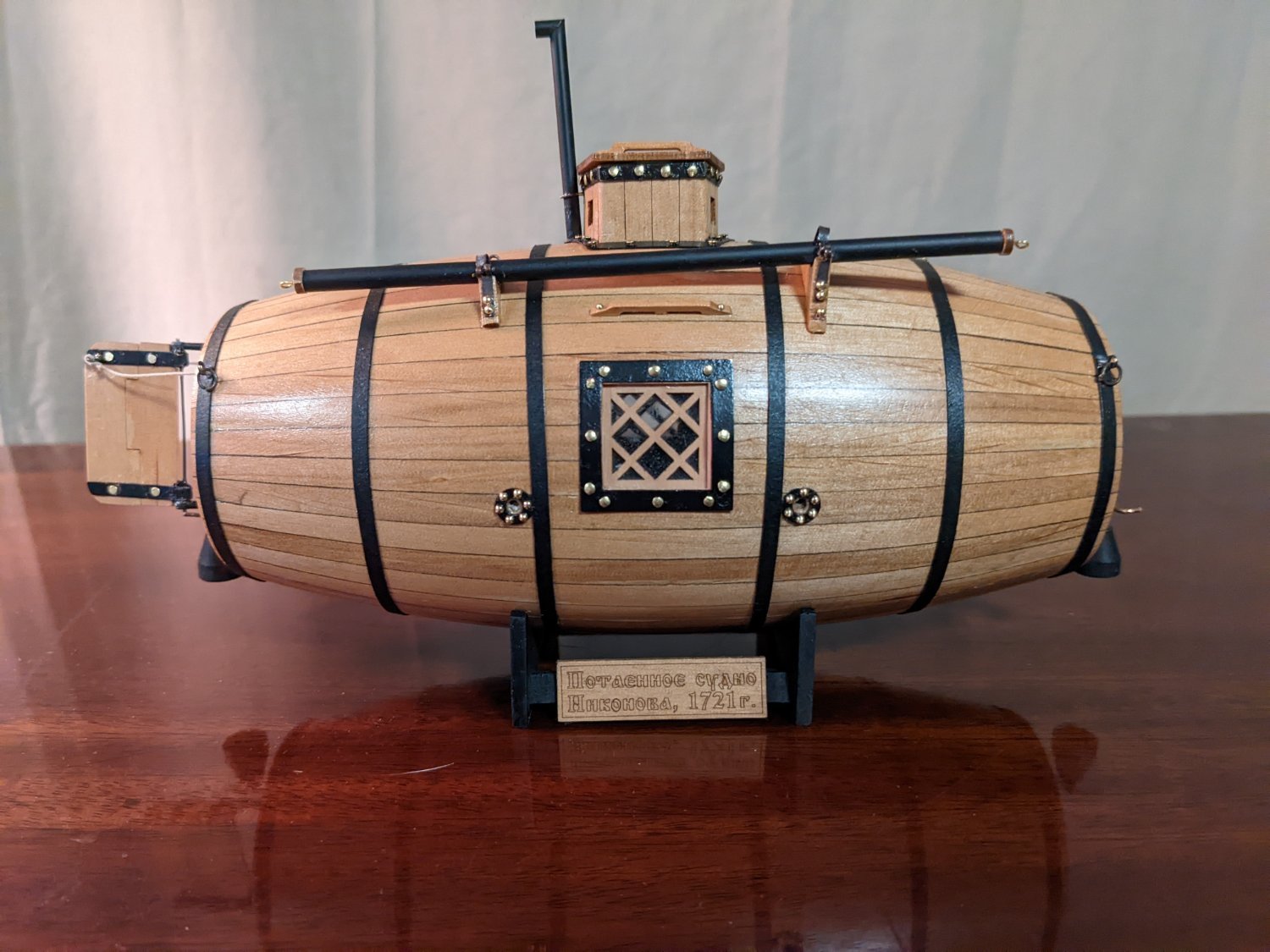
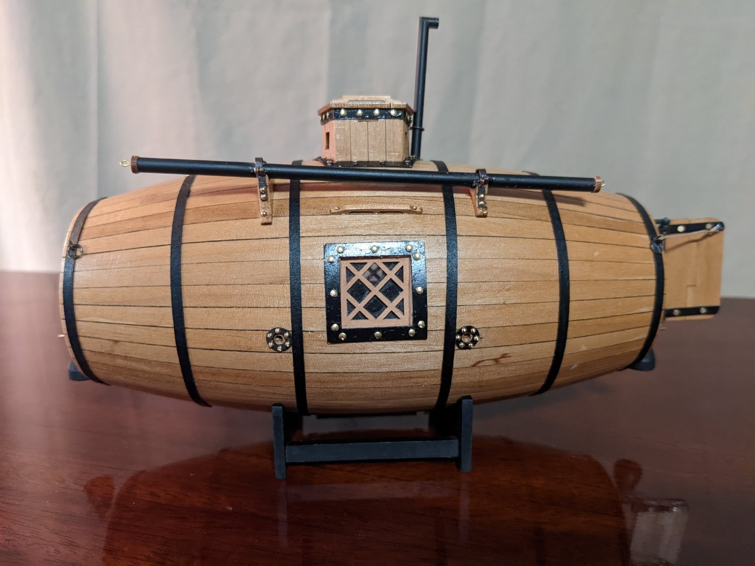
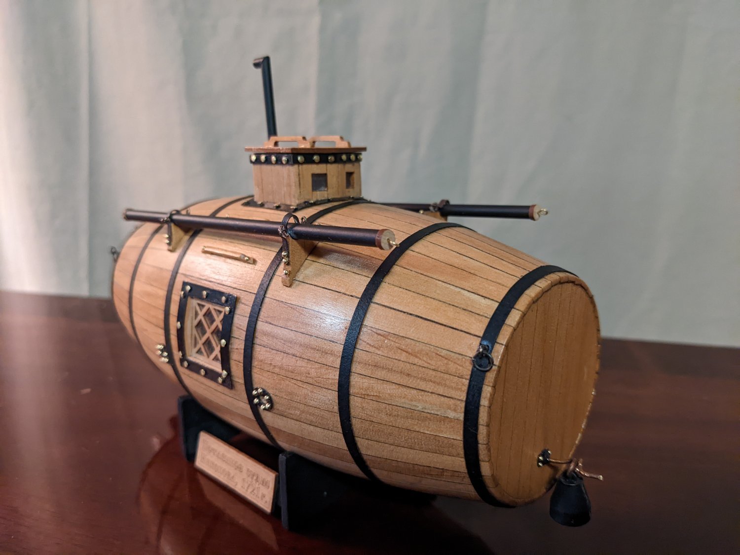
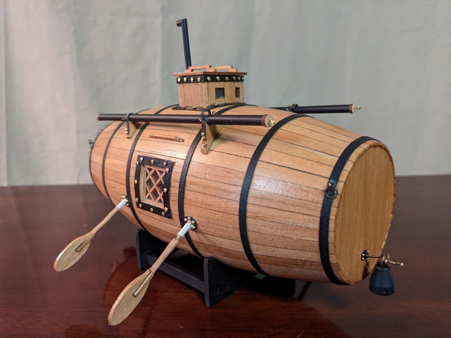
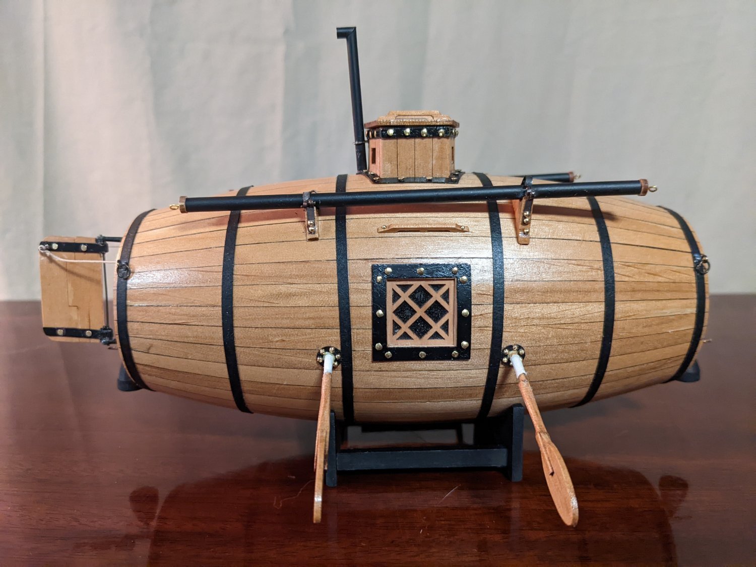
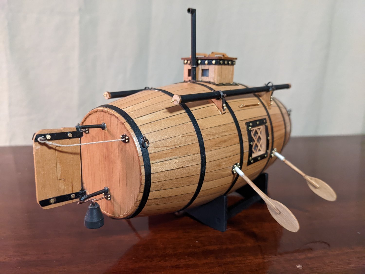
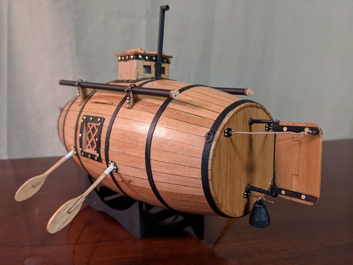
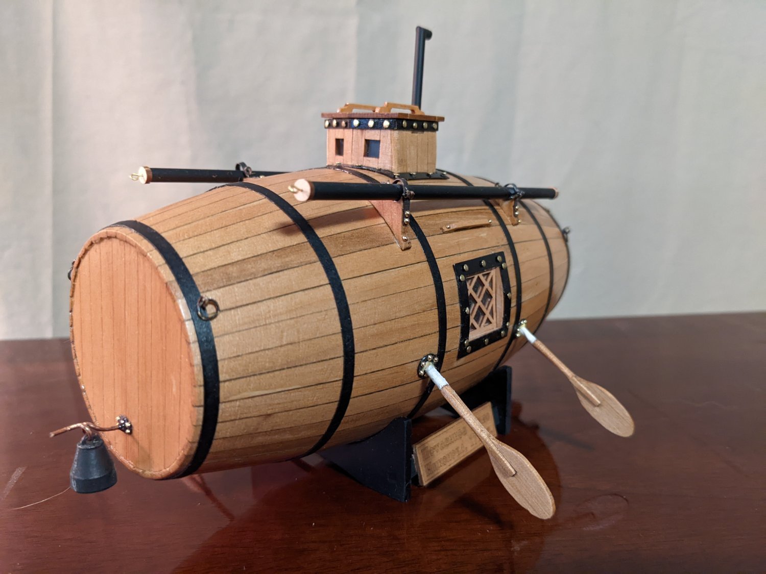
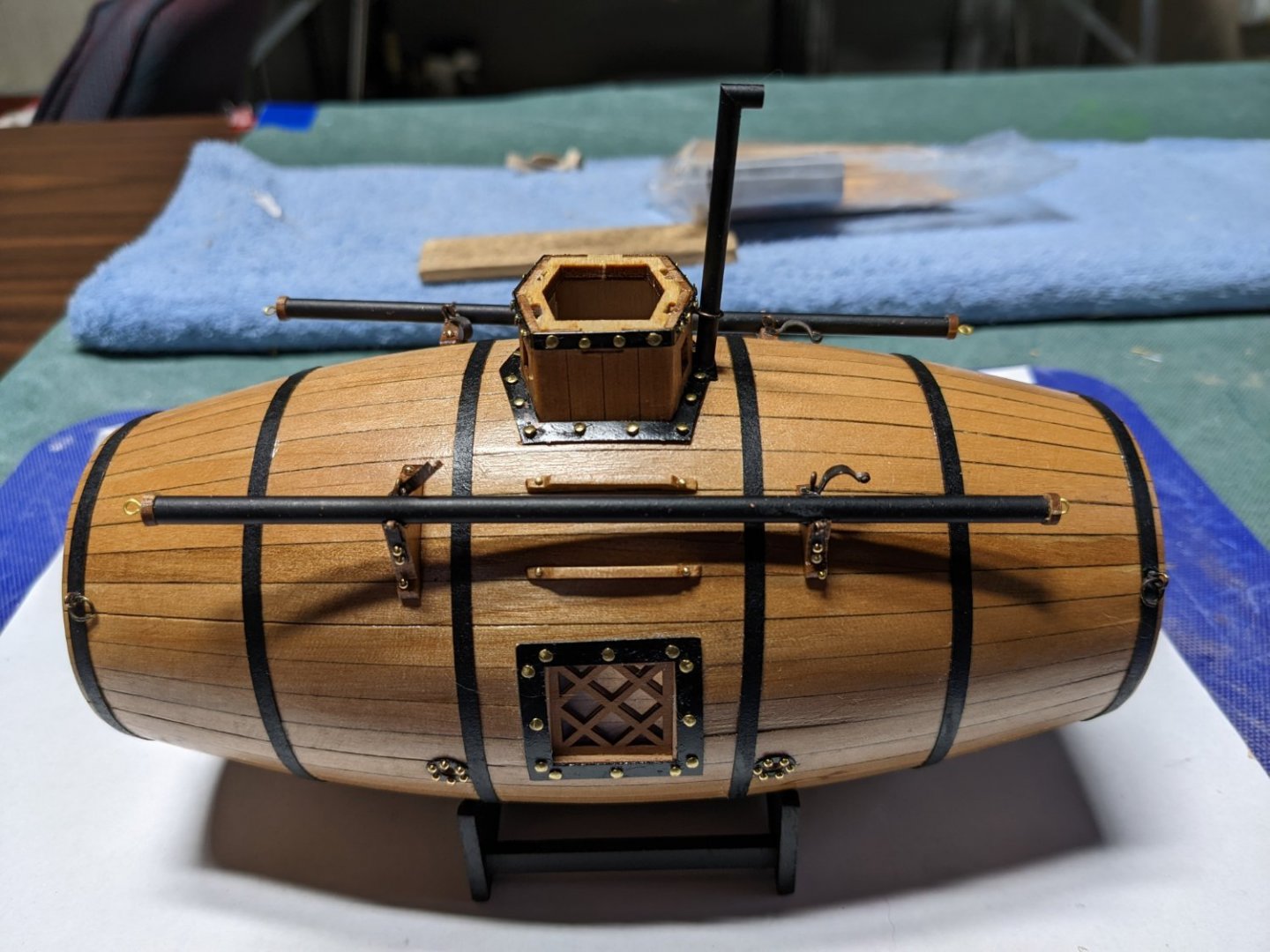
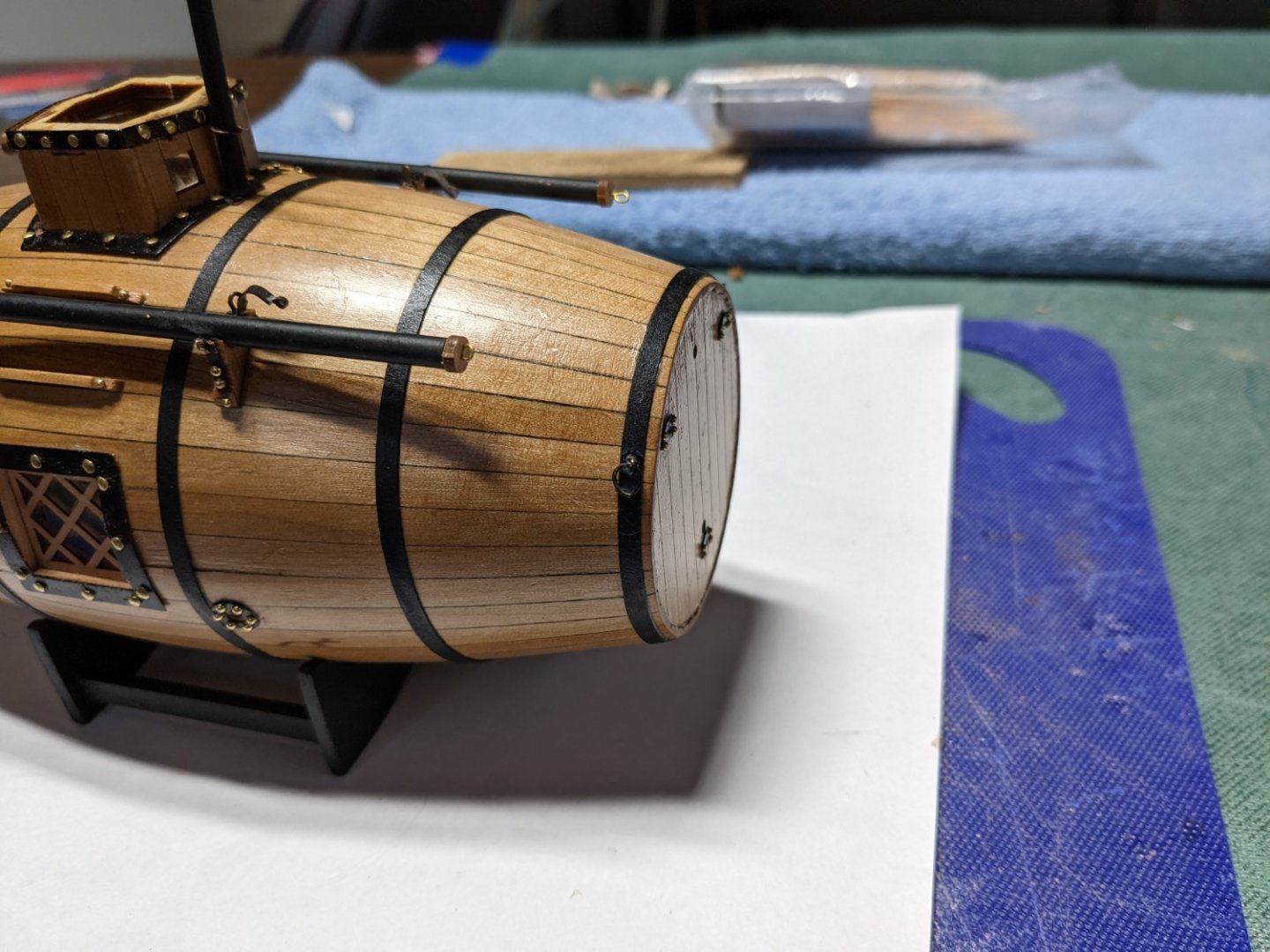
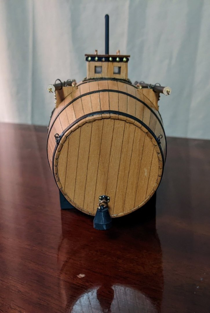
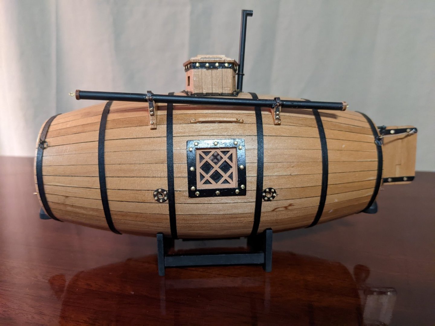
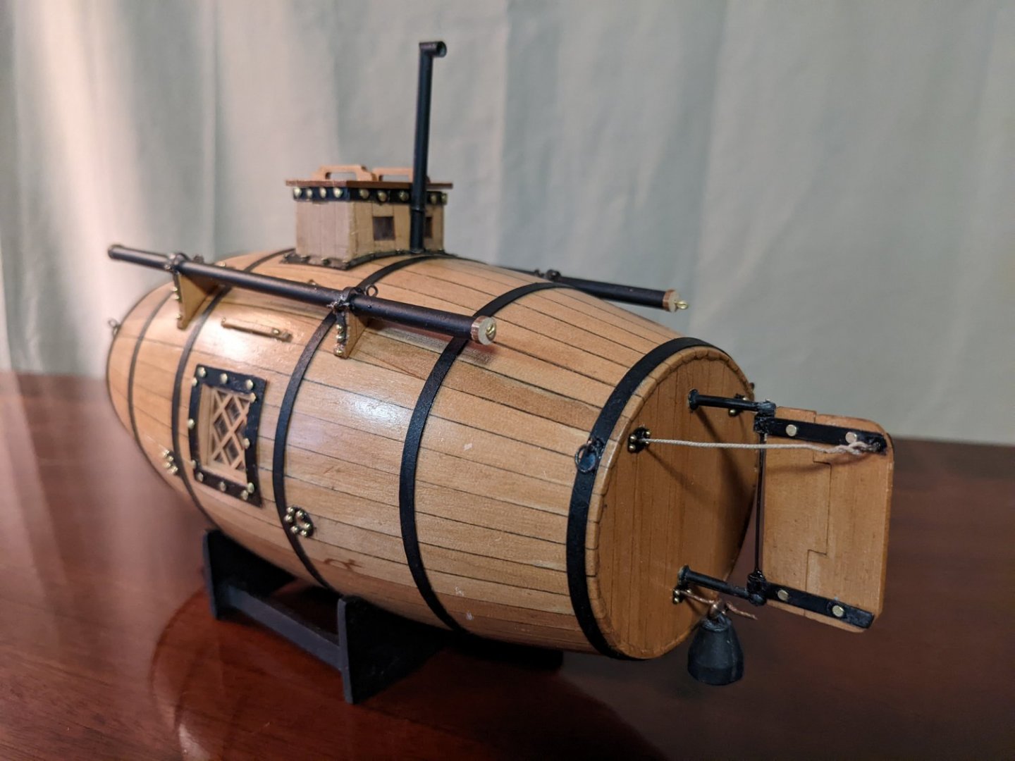
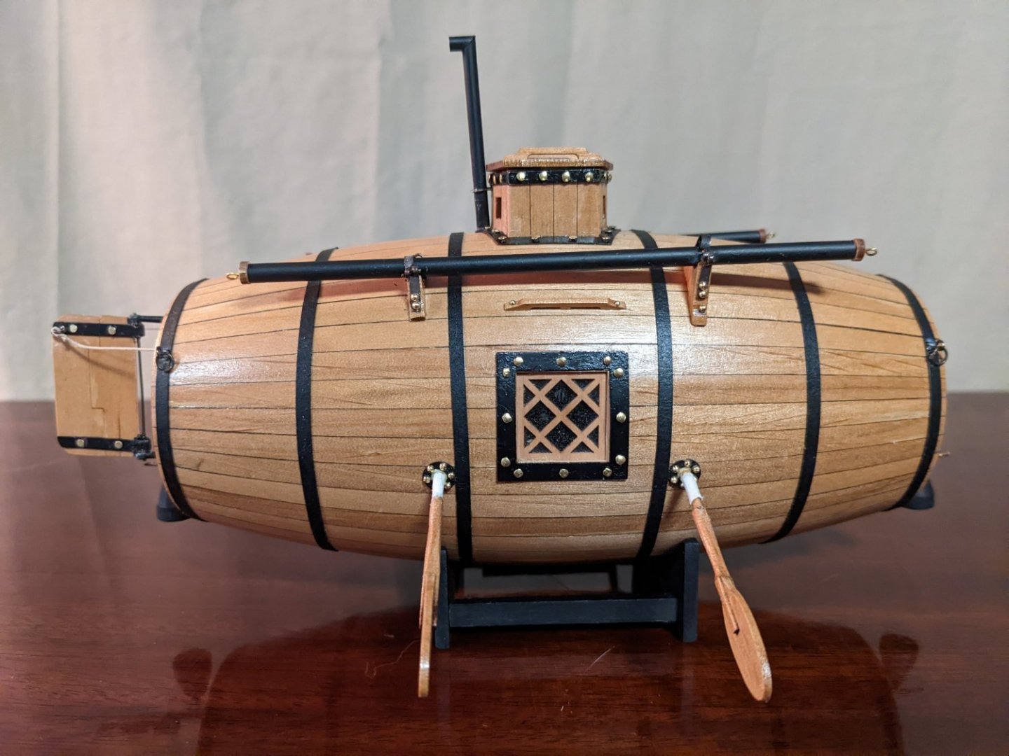
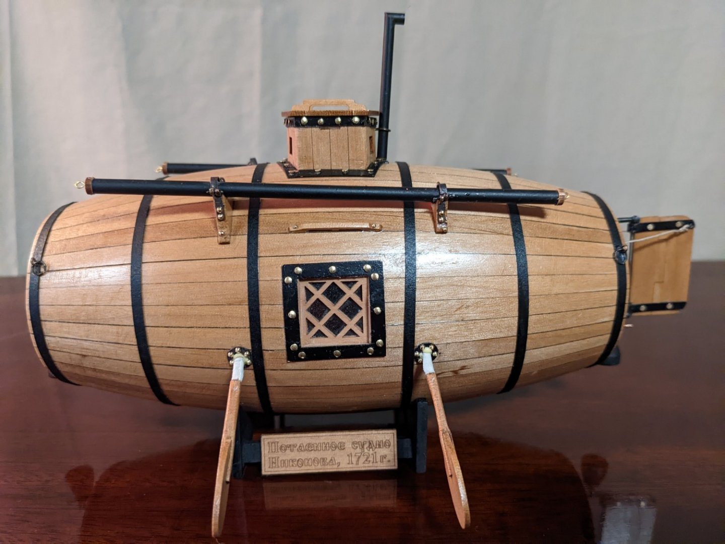
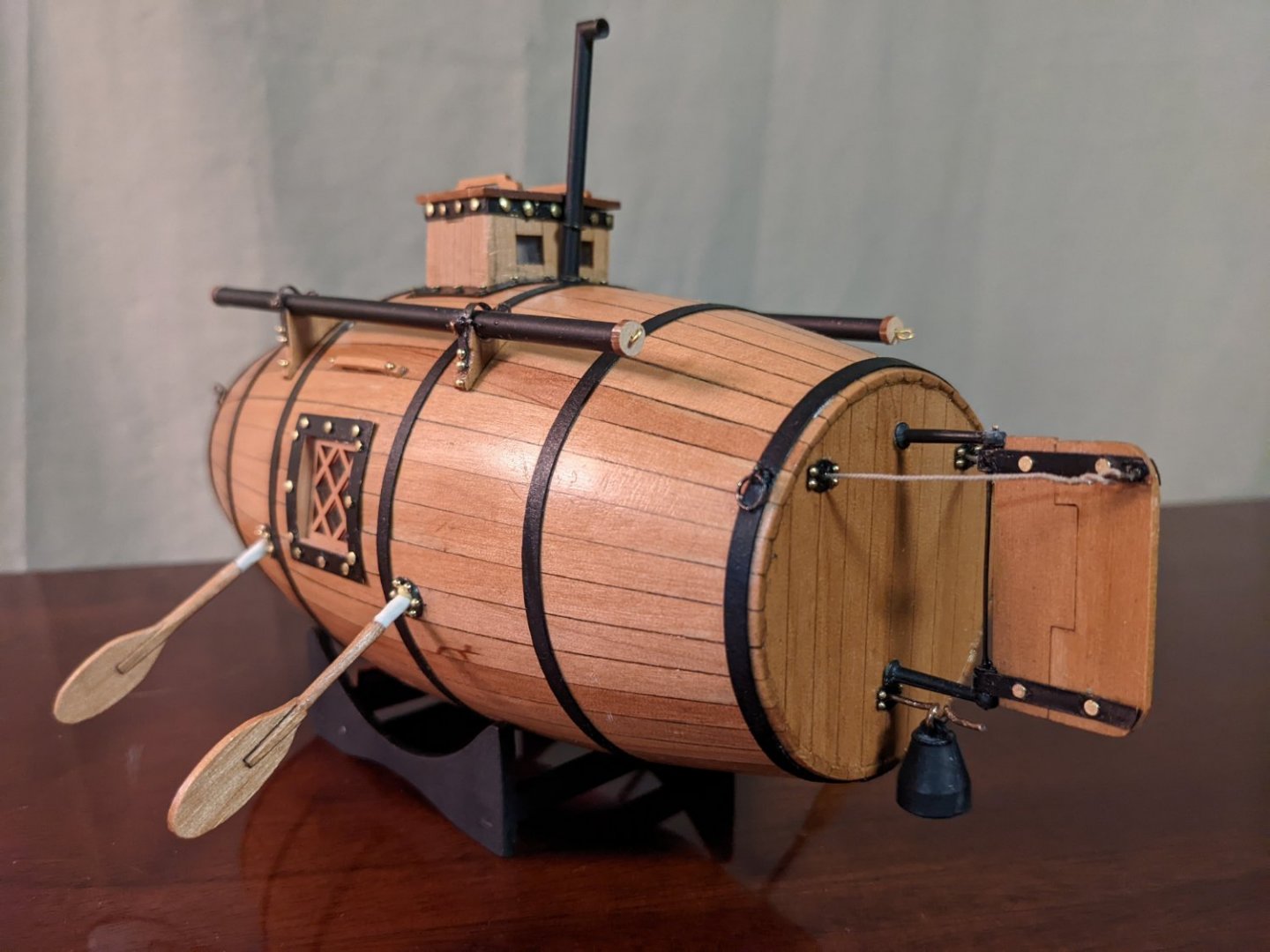
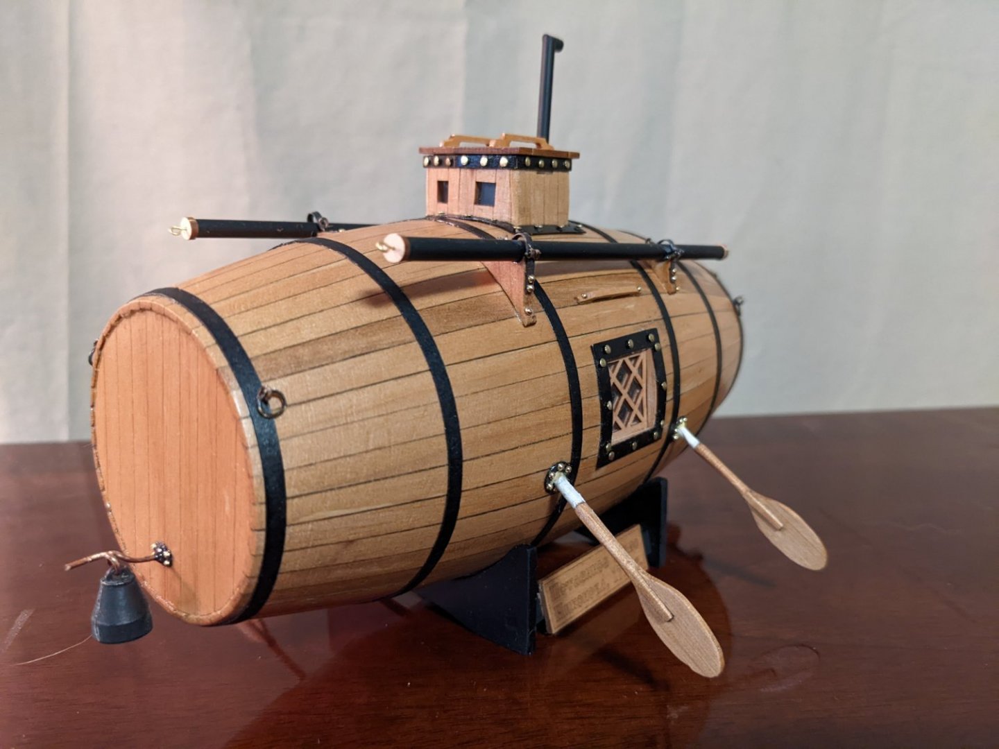
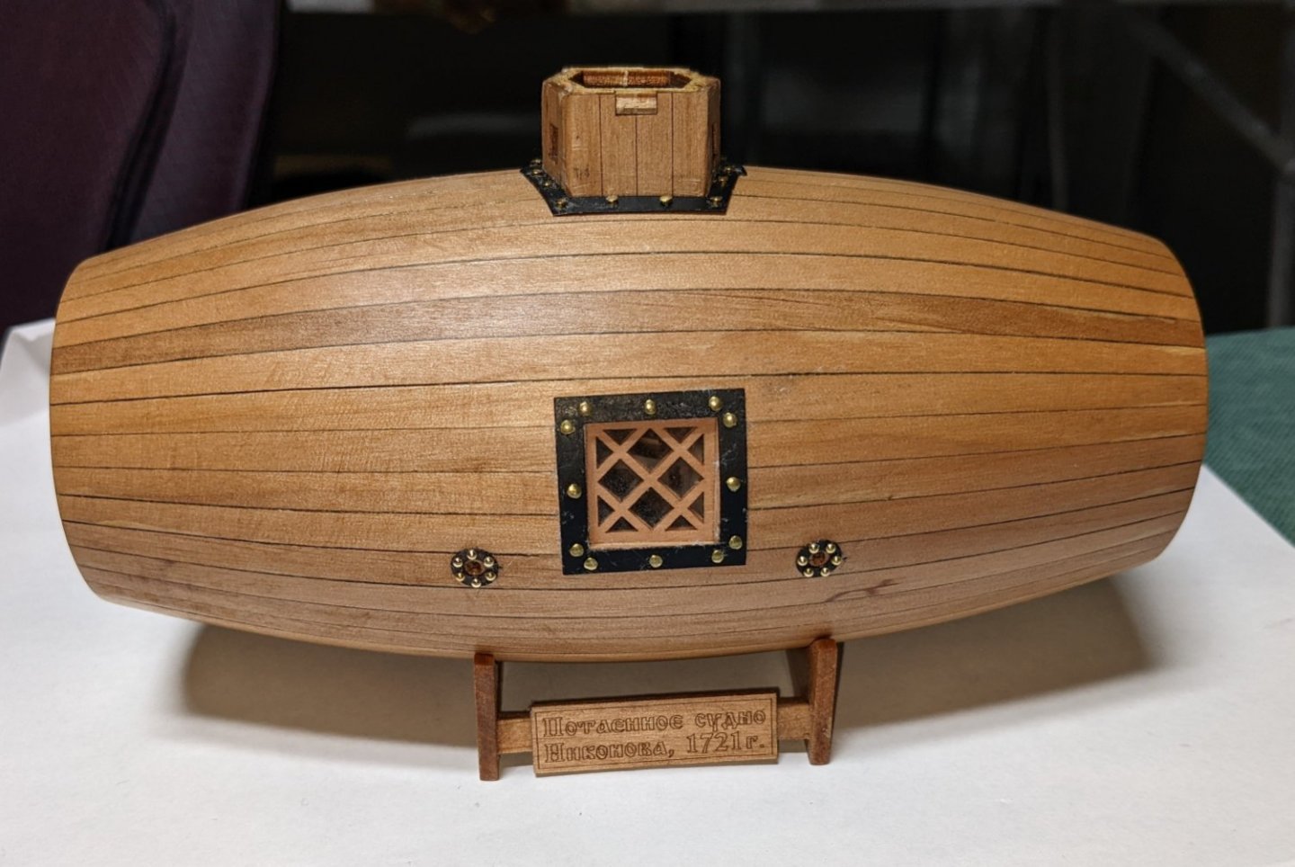
The metal straps (actually paper) have been glued to the hull. For the four rings that go on the outer straps, the instructions call to make the eye bolt and rings out of the .6mm wire. Not sure I had the talent to make a good ring but I gave it a shot, and to my surprise actually made from pretty fair circular rings out of the wire. Not as hard as I thought. Fiery pipes attached but not fully strapped in yet. I ended up using one 1.2mm pin to pin the fiery pipe supports to the hull. I figured since they were being glued to the varnished hull, they might need a little more support. Closing in on the end.... Ballast weights have been attached at bow and stern and the rudder attached. To get the steering line into the holes in the stern, .6mm line was used and the hole in the hull was increased to .9mm. From there the line could be inserted (poked) into the hull by a 28 gauge wire with a drop of CA glue on the end. Worked far easier than I thought it would. Fiery pipes have been fully strapped in. All that is left are the oars...... Once inserted I am calling it..... I have totally enjoyed this build and as I mentioned earlier is a nice break from the year long marathon builds I have done in the past. Kind of like a reset before I start my next marathon build - Chaperon Sternwheel Riverboat. There are not a lot of areas to customize this boat, and features like the flooring, benches, and ladder inside the hull are not even visible. If I ever built this one again (and I have thought about it) or for someone who wanted to do a lot of custom work, one idea would be to open up a portion the hull and show the inside of the ship. From there one could do all sorts of custom stuff inside of the hull. Might be an interesting build. Final pictures are below..


- 36 replies
-
- 9
-
-
- Morel
- master korabel
- (and 1 more)
-
Not a lot of progress today,,, only have a short time to work on it.. Today was the installation of the side ladders (or that is what the manual calls them). To me they look like large "hand holds" between the hatch and window. Here I used the 1.2mm pins as they seemed to be the correct size. Port Side Starboard side The oars, fiery pipes and fittings, rudder, and ballast weights have previously been completed. Plan to add then on in the next few days. At that point I will "call it"... done....


- 36 replies
-
- 3
-
-
- Morel
- master korabel
- (and 1 more)
-
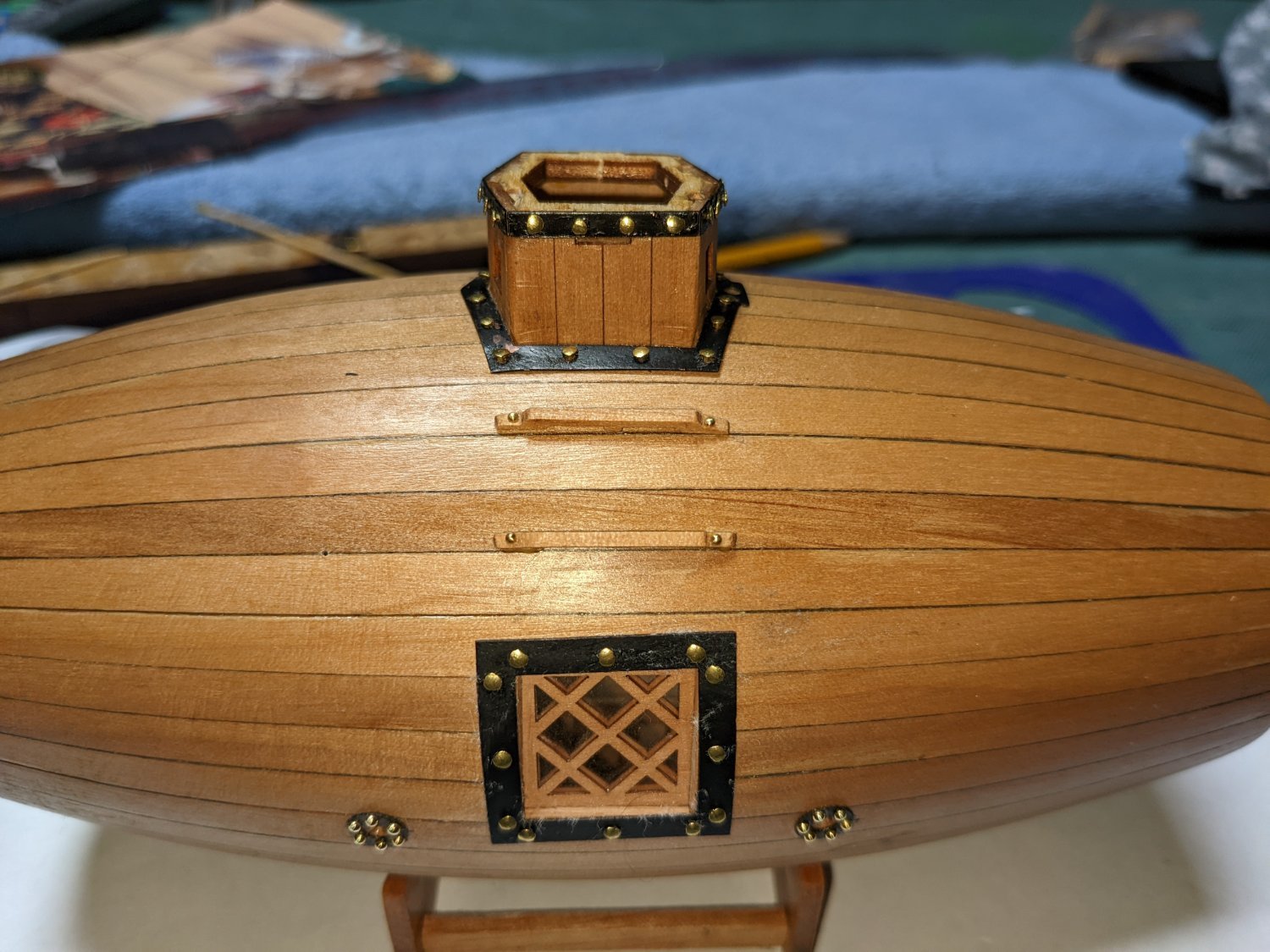
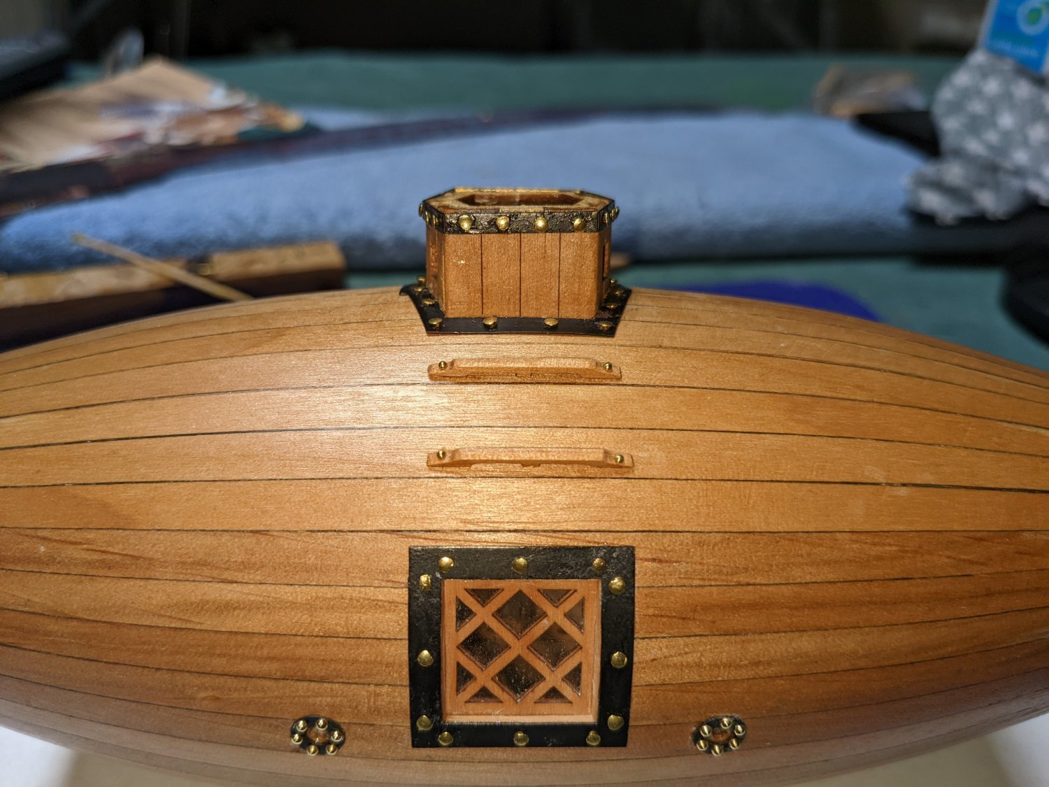
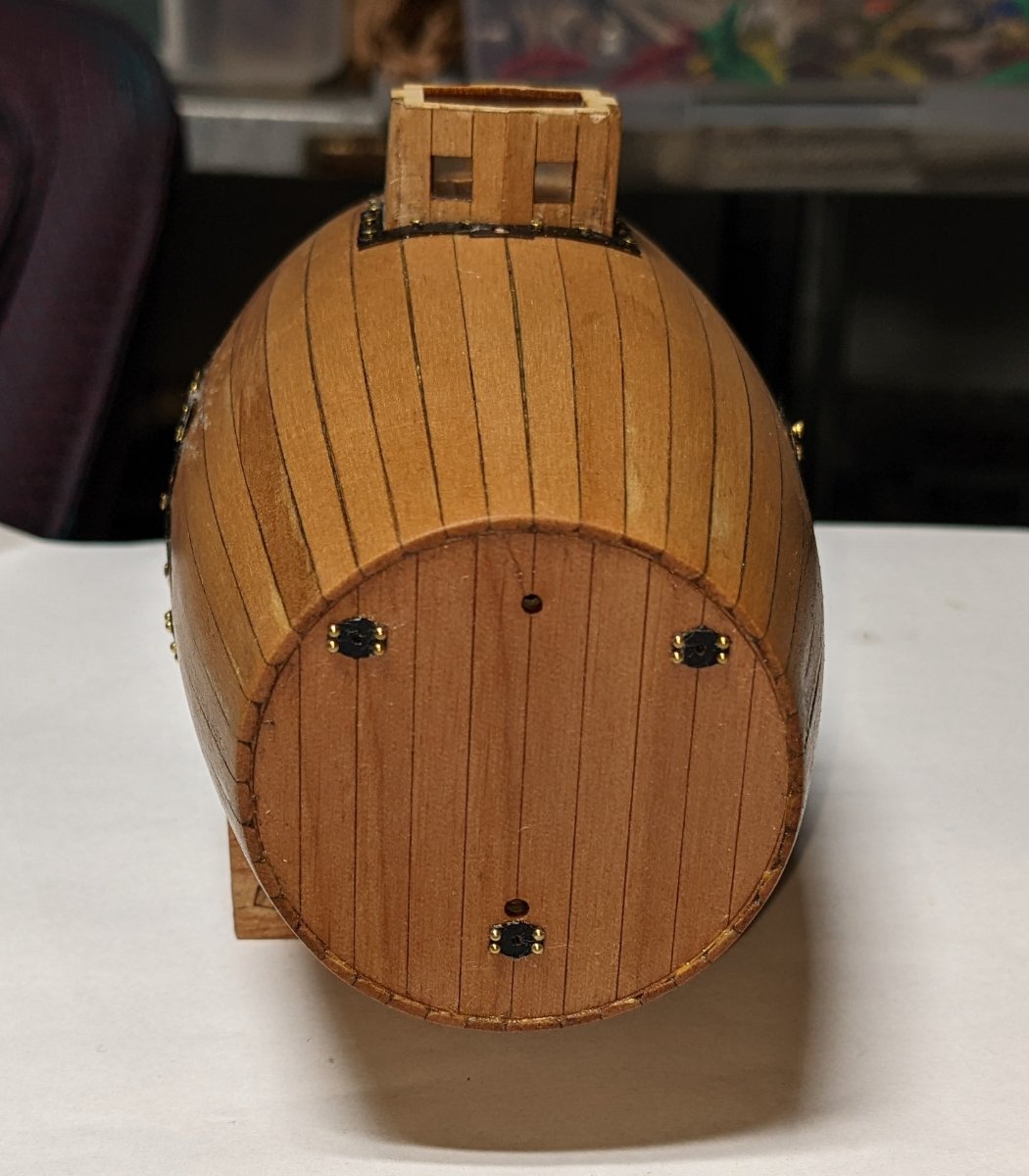
Have completed sanding and a couple coats of wipe-on poly. Hatch cover still need a little work as it got a little scraped up sliding the metal framing over the hatch. A little sanding and more wipe-on poly should do the trick, I have also added the metal framing around the hatch cover, windows, and parts in the bow/stern. Port Side.... Here I used the nails supplied with the kit for around the window. The nails around the oar ports where the 1.6 mm nails as the kit supplied nails are just too large. Starboard side.... Same as on port side. Kit supplied nails around the window and 1.6mm nails around the oar ports Stern view... Here even smaller nails were used (1.2mm) around the steering line ports and ballast port Bow - again 1.2 mm nails used around the ballast port Top view showing the nails around the hatch. Here the large kit supplied nails were used
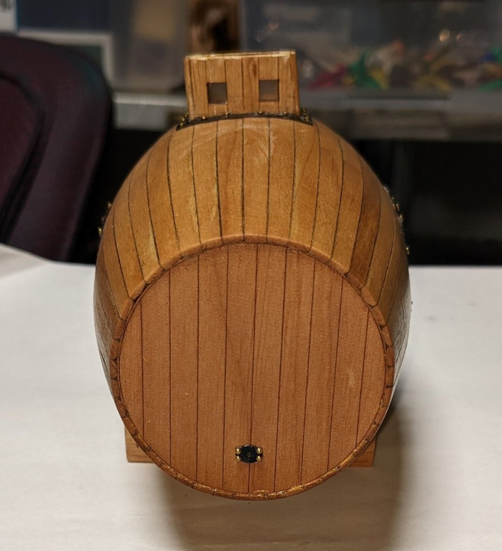
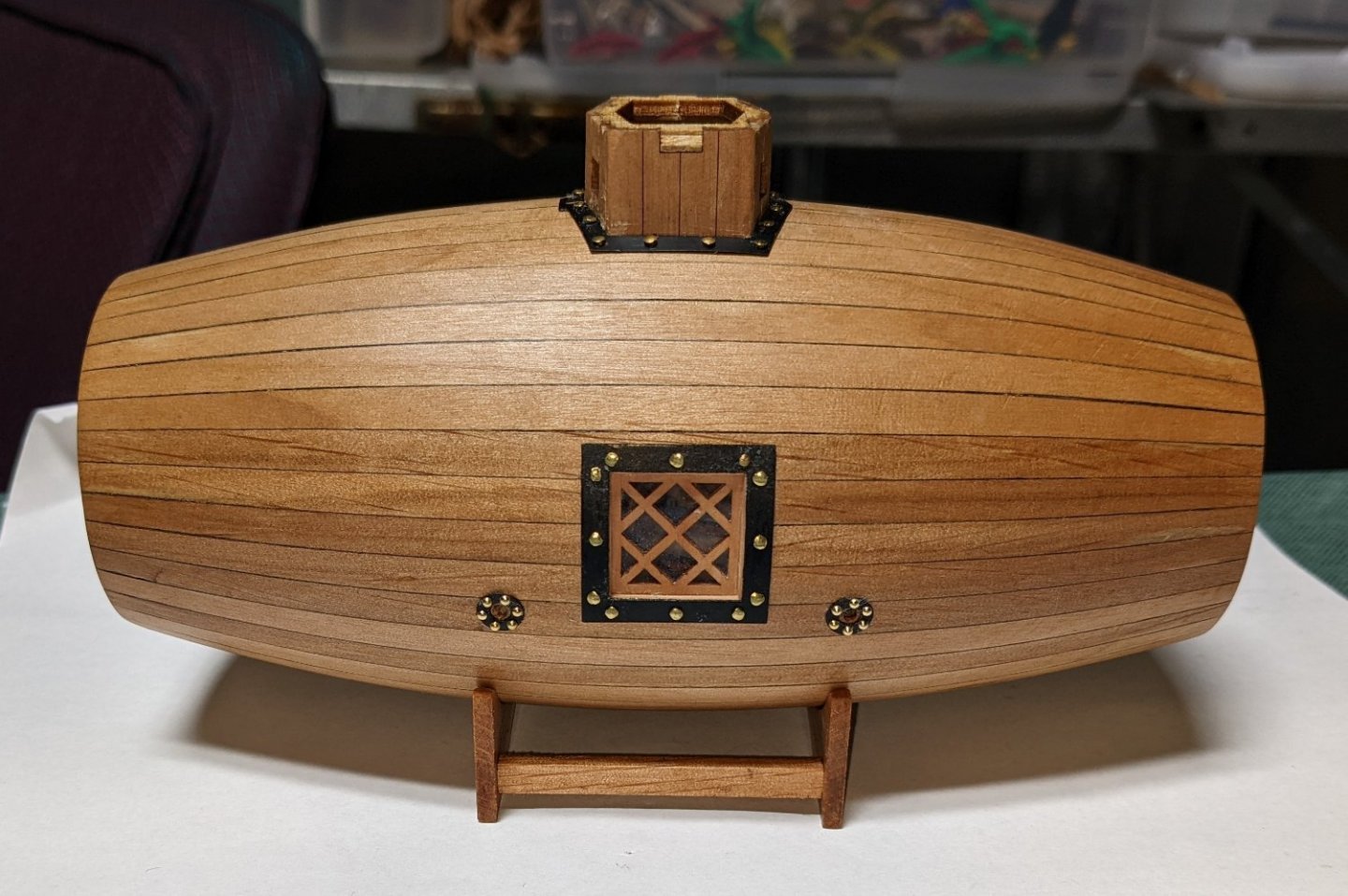
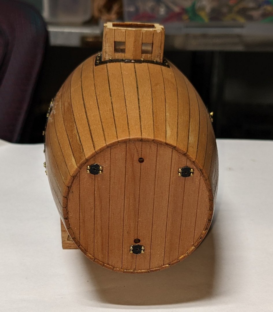

- 36 replies
-
- 5
-
-
- Morel
- master korabel
- (and 1 more)
-
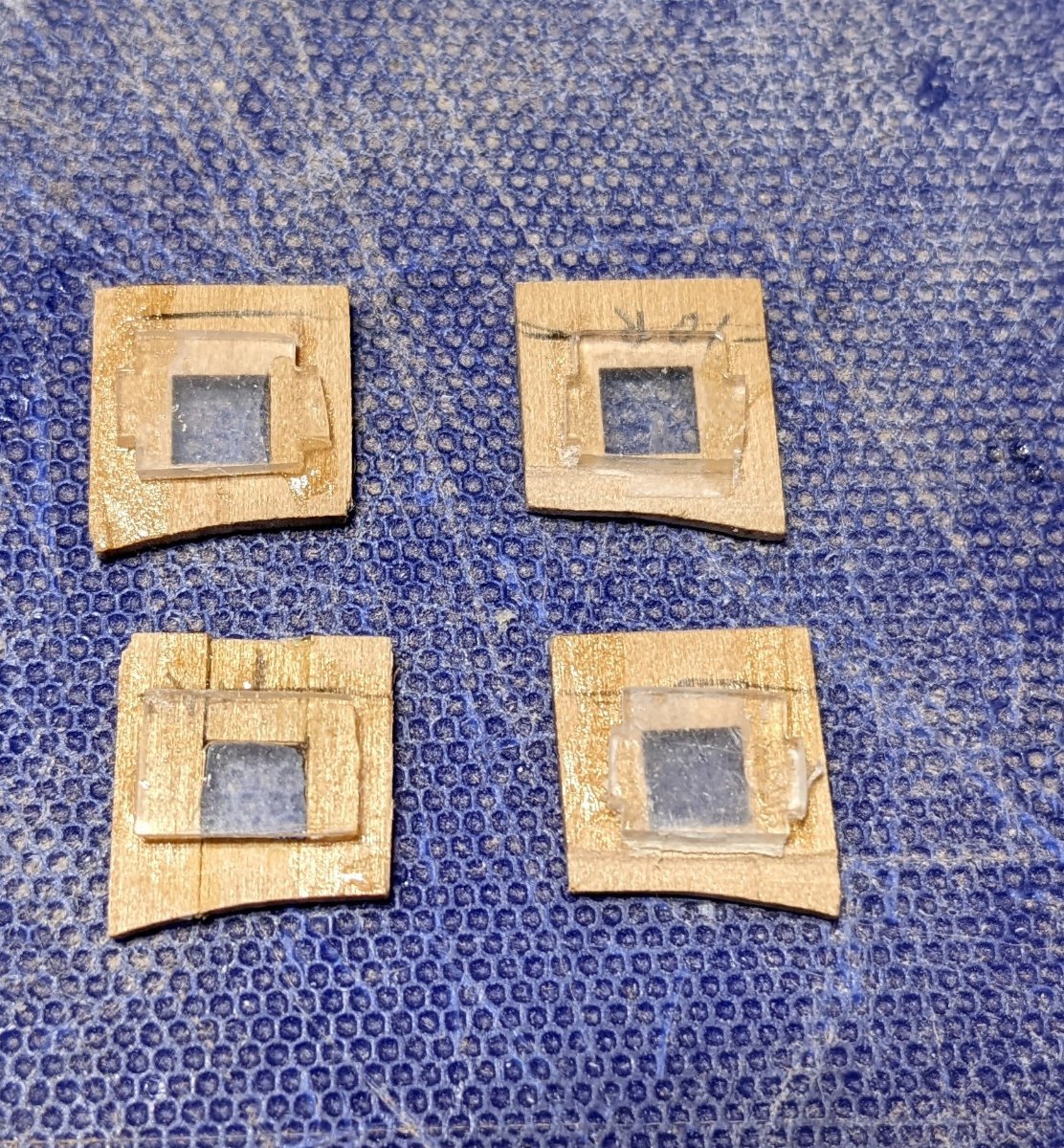
Still have some final sanding to complete, but the hatch panels have been installed. Without the issue of the windows getting in the way, the panels could easily be trimmed on the bottom and sides to match up pretty well. As mentioned earlier, in hindsight, and for those that follow me, I would suggest you dig out the hatch top and bottom panels so that the window are completely imbedded into the binding. Windows sunken into the binding is far better then having the window even with the binding. The panels (and bindings too) will take some (shall we say) "customizations" and not having to worry about the sunken windows make the job a whole lot easier. But if you still have an issue,,,, do like I did and glue the windows to the panels and then you will not have to worry about them getting in the way as you trim things up. You just have to trim the glass to only be slightly larger on the top and bottom so that it does not get in the way of the bindings. You can have extra glass on the sides for a better gluing surface. Stern view Bow view And a couple side views


- 36 replies
-
- 3
-
-
- Morel
- master korabel
- (and 1 more)
-
I mentioned earlier that I was pretty sure when the glass windows (currently mounted to the top hatch bindings) was going to get (shall we say) "interesting" when trying to line it up with the lower hatch bindings. Turn out it was "interesting" but in a way I was not expecting. Turns out the glass windows on the upper binding fit pretty will when it was joined to the lower binding. The "interesting" part was getting the hatch panels lined up. Trying to get them lined up, on the bottom with the hull, and on the sides with each other. turned out to be a challenge. Main problem was the fact the the glass pieces were inserted into the top and bottom bindings. In my case I only fitted them into the inserts to where I thought they were fully inserted (flush) into the bindings. Turns out my pieces was a little warped and it stuck out just a slight amount from flush. This prevented me from getting the bottom and sides of the panels lined up for a good fit. I fiddled and fiddled with it but the inserted glass pieces really hampered my ability to trim the the panels for proper alignment. I finally gave up and decided instead of inserting the glass panels into the binding, to just glue the glass to the actual panels. Below shows the panels glued to the inside of the panels. This way I could properly fiddle (trim) the panels and the bindings without worrying about the inserted glass panels getting in the way. Only thing you have to deal with is the width of the binding as it overlaps the panels. Note below the glass panel is just below the lower window. Any lower and the lower binding would hit the glass. From this point the side panels could be glued to the top binding and attached to the hull. From there the side panels could be easily adjusted to get a good alignment. All you have to worry about is correct fit on the sides and bottom. The top of the panel will be covered by a brass band, so if you need to "fudge" the top of the panel does not need to line up exactly. In hind sight a better way would be to over insert the glass windows into the bindings, but that would involve trimming the already attached lower binding and I felt just gluing the glass to the panels was and easier solution. Easier for me that is... A better skilled builder probably would have a better solution. Below shows the side panels glued to the top binding and hull. With the glass glued to the side panels it should not be a problem trimming and inserting them for a good fit. Famous last words,, we will see how easy it will be when the glue dries and I attempt to put in the panels. 🙂

- 36 replies
-
- 1
-
-
- Morel
- master korabel
- (and 1 more)
-
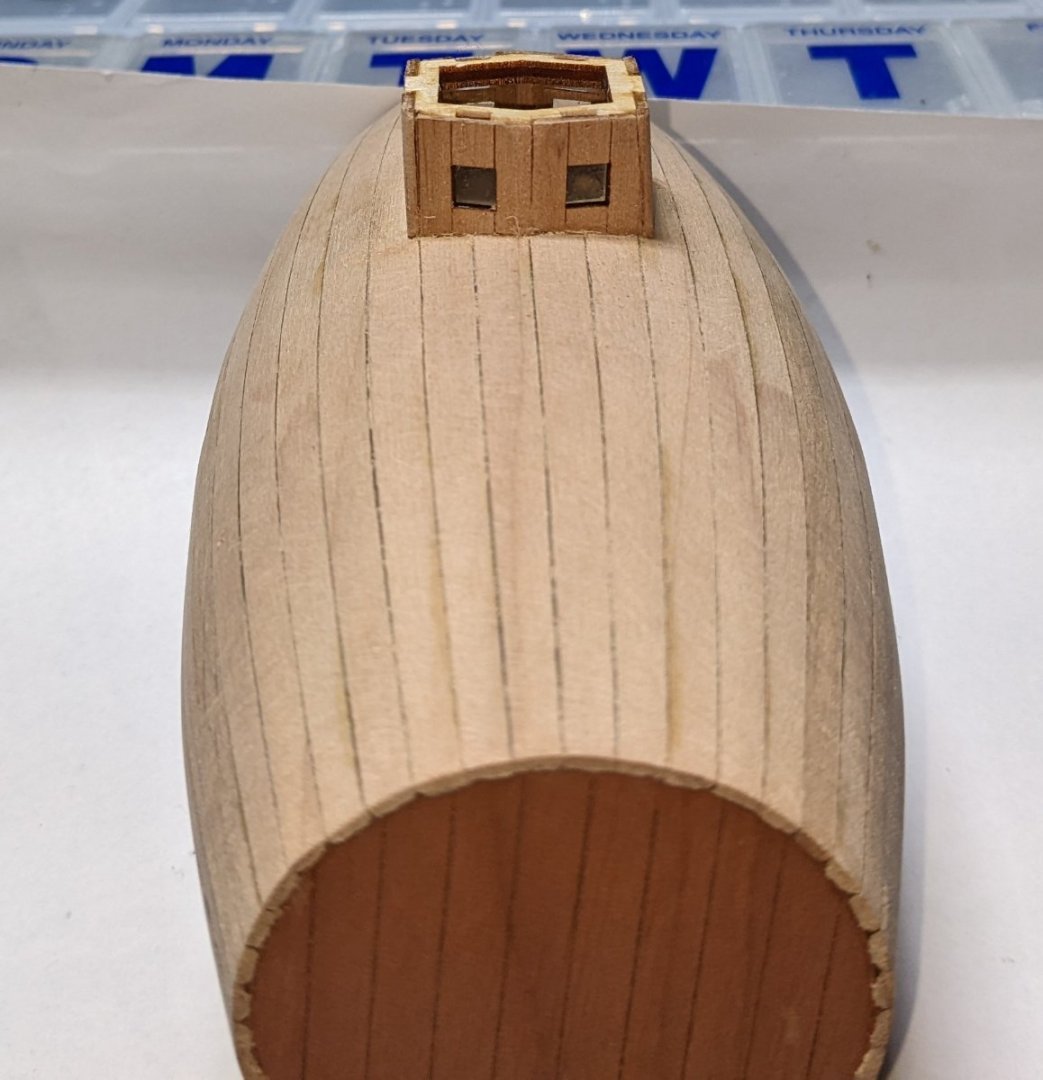
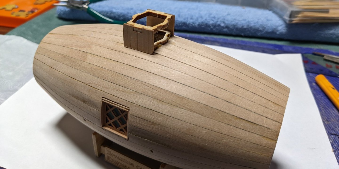
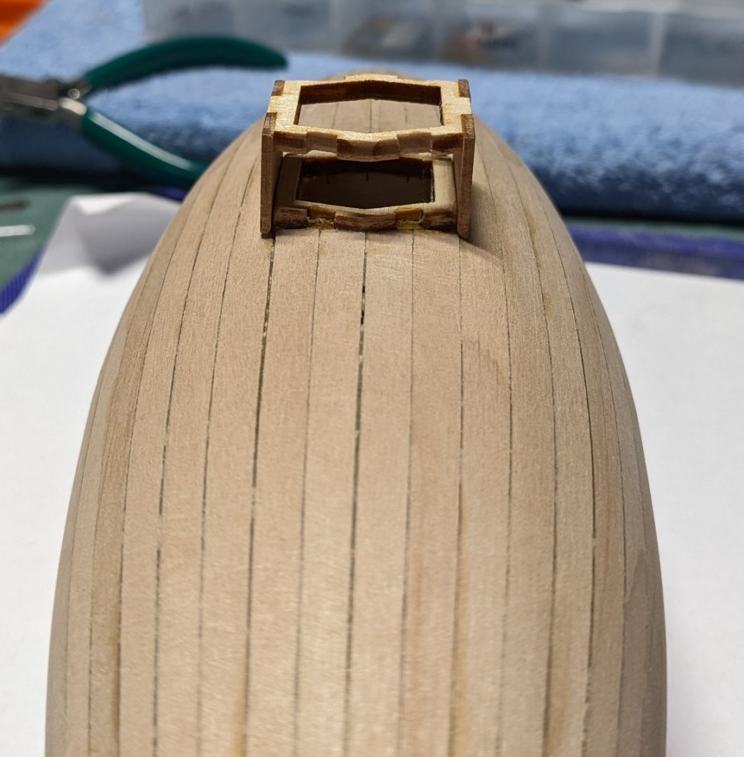
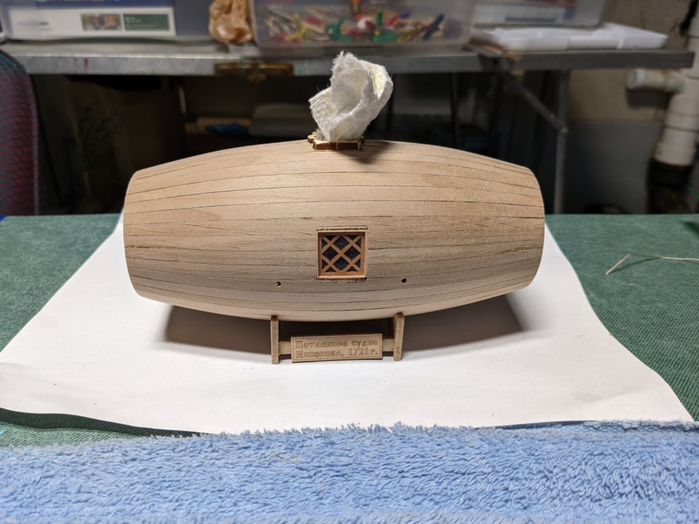
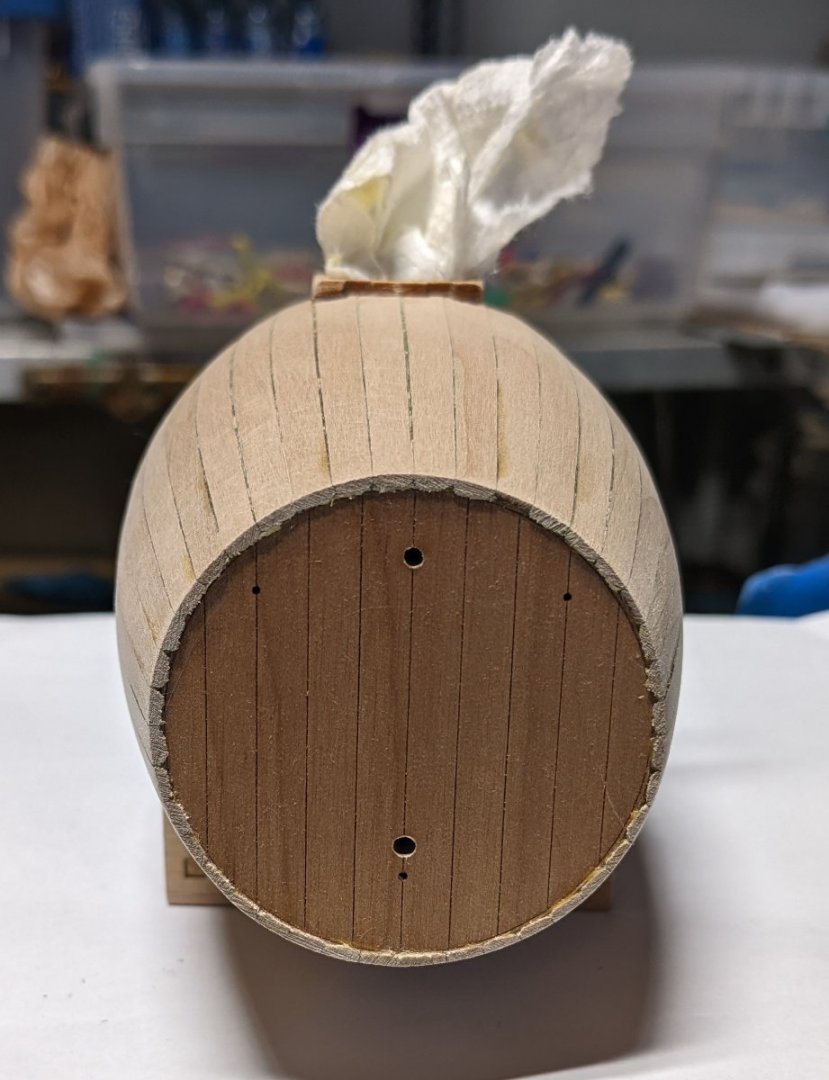
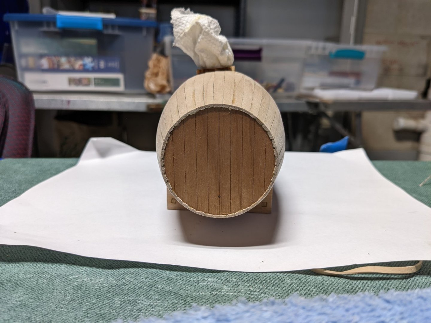
The last plank was finally installed and a rough sanding completed. Still have to work with the window sashes some to clean them up too. As noted before, I would suggest you resist any sanding during planking until the windows have been installed. I addition, put a small rag into the open hatch on top. With the windows installed and the rag on top this will keep the sawdust from sanding out of the hull. Port Side Aft or read end Starboard side Bow or front end
- 36 replies
-
- 1
-
-
- Morel
- master korabel
- (and 1 more)