John Gummersall
-
Posts
265 -
Joined
-
Last visited
Content Type
Profiles
Forums
Gallery
Events
Everything posted by John Gummersall
-
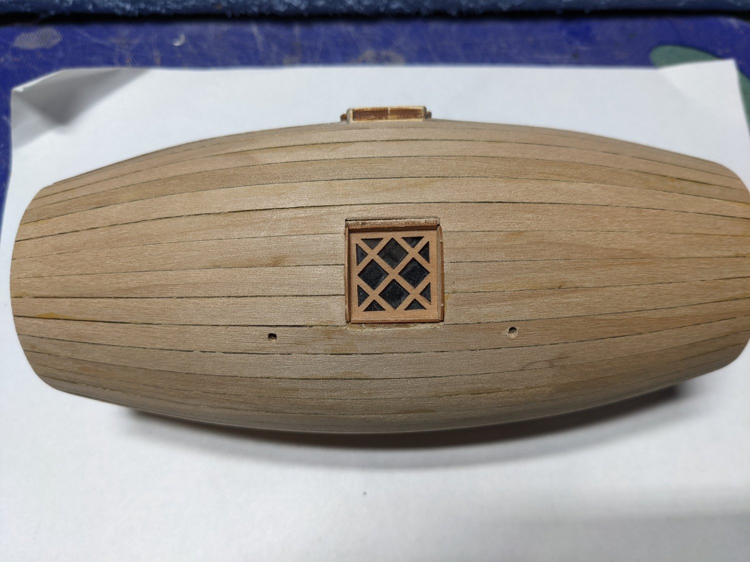
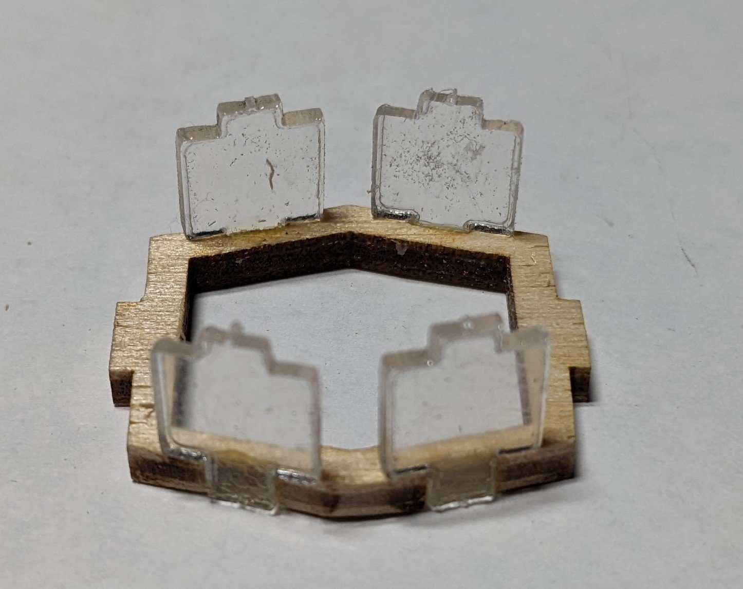
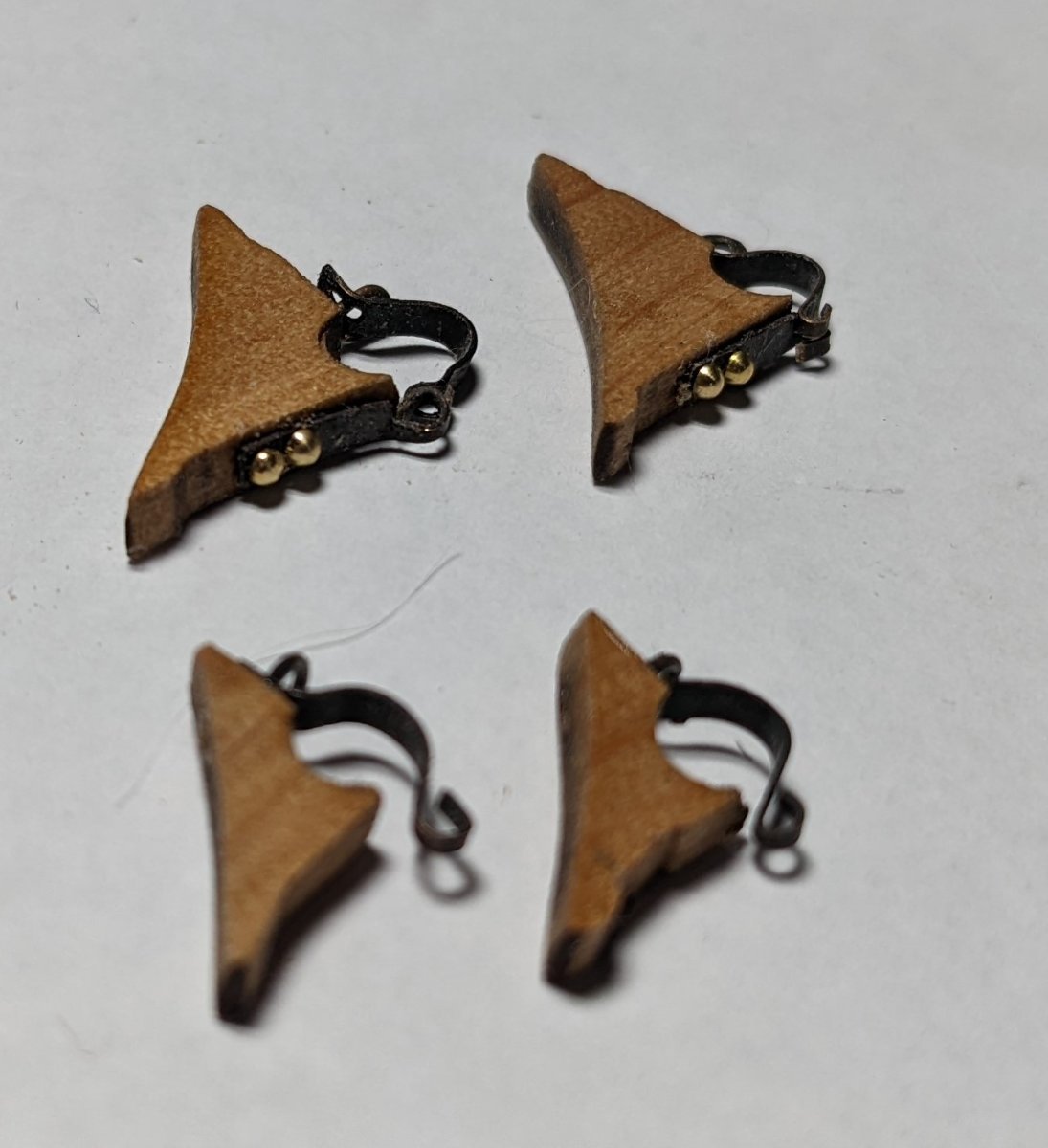
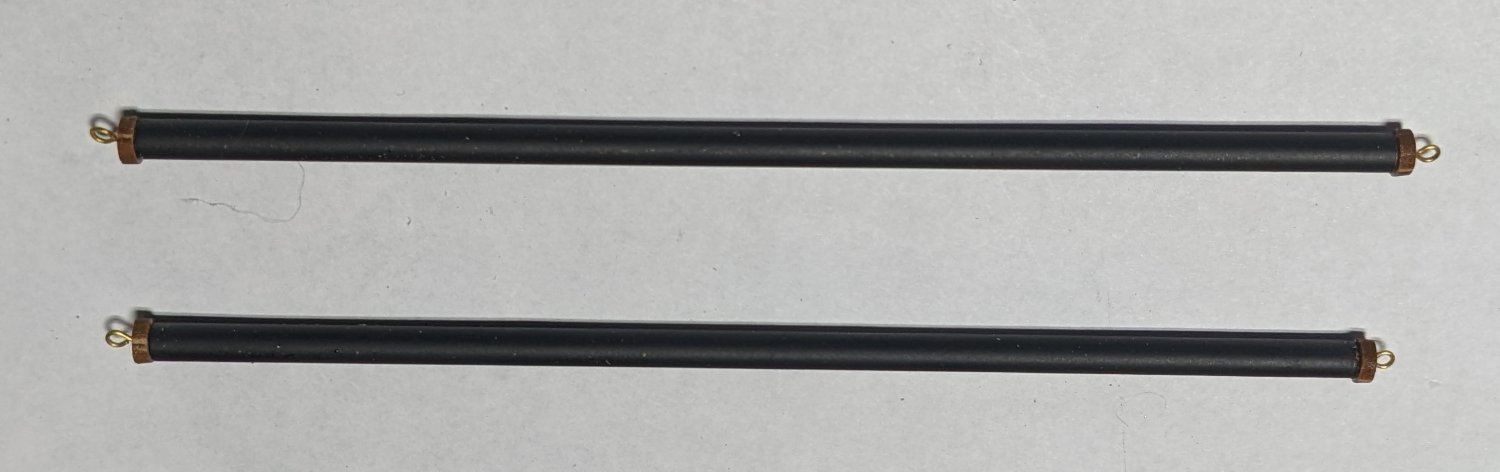
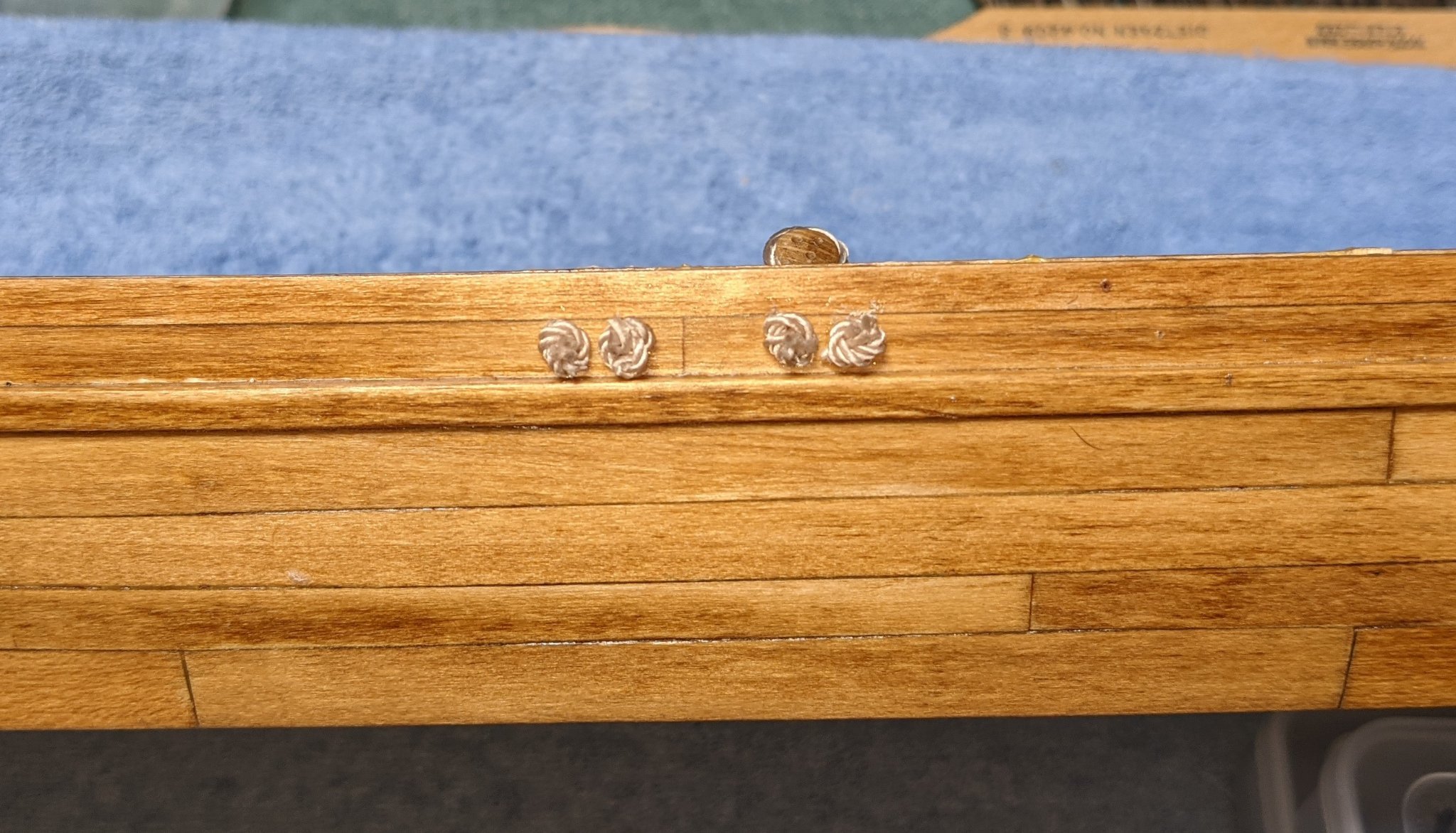
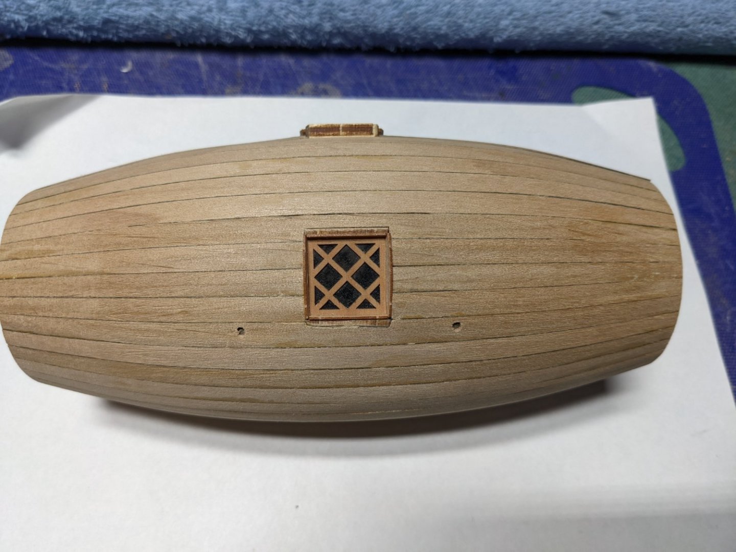
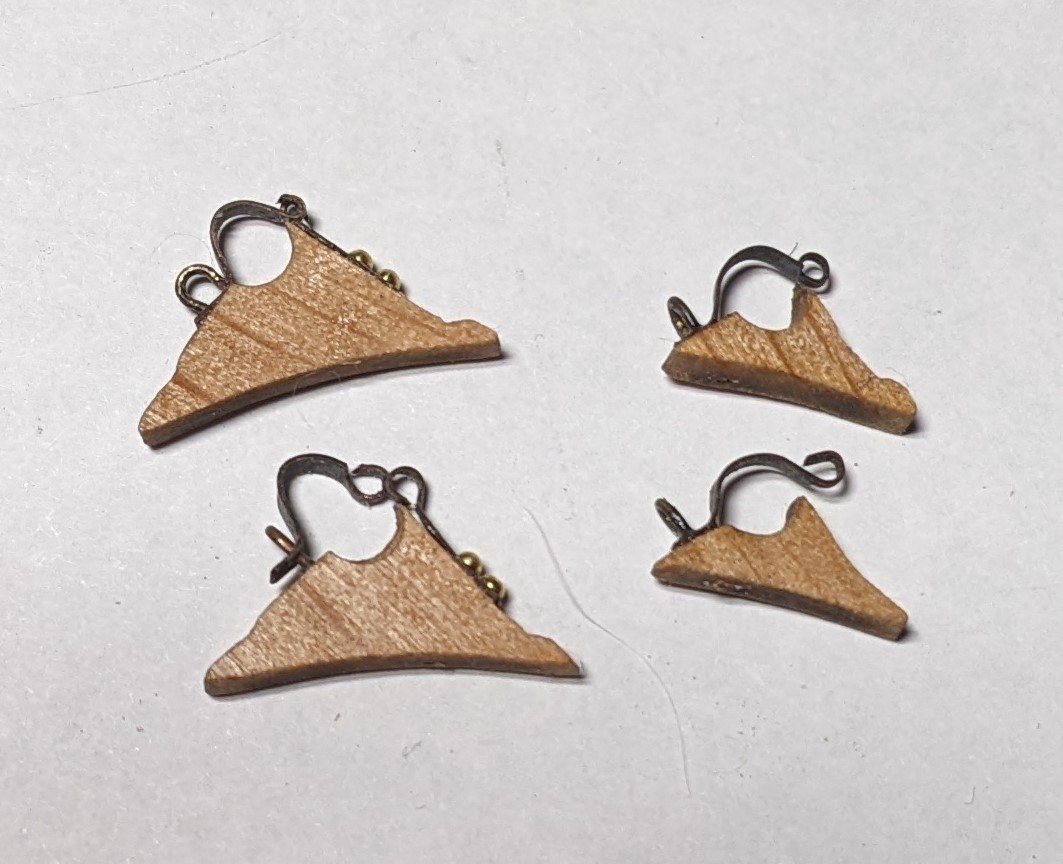
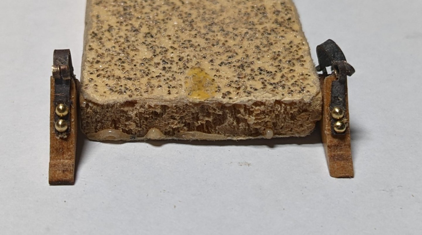
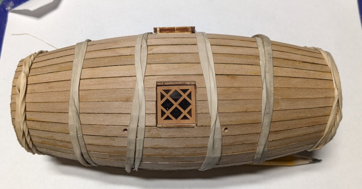
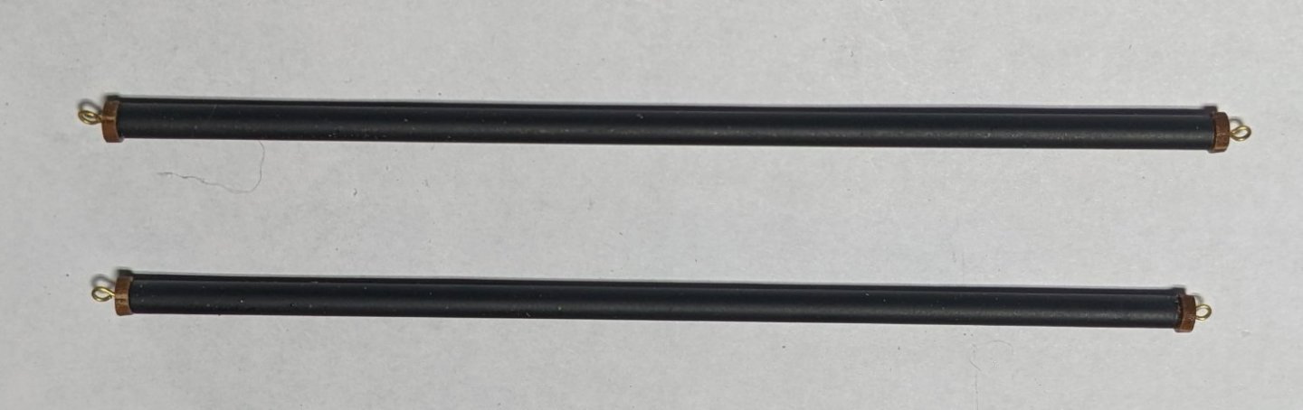
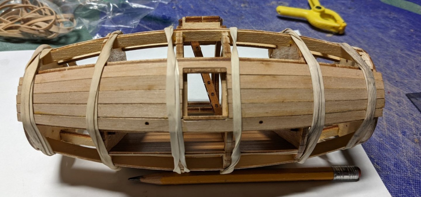
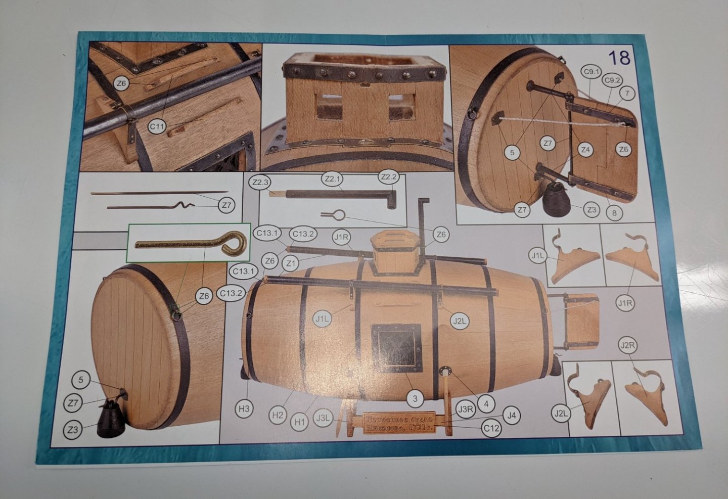
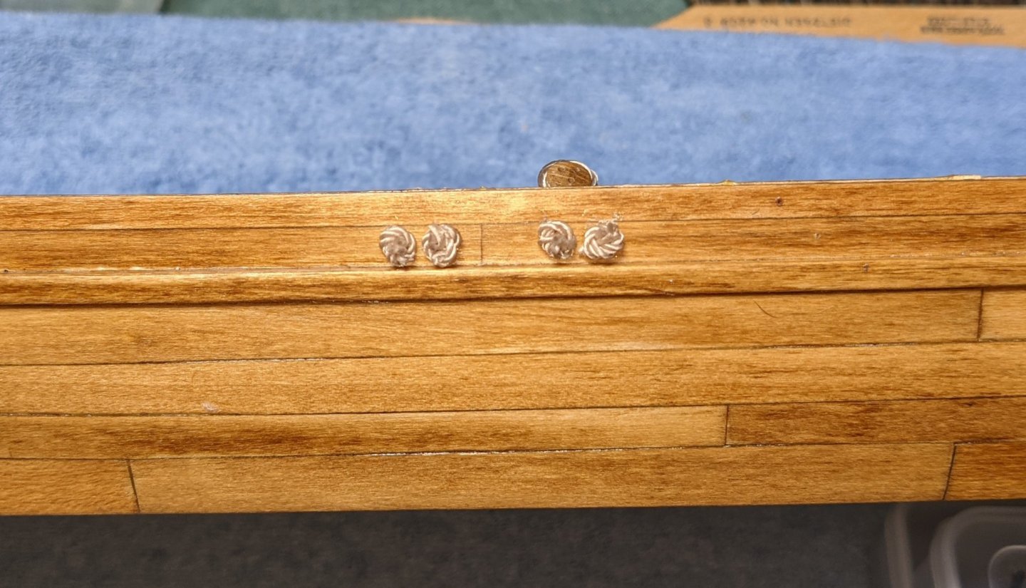
 HardeeHarHar It is truly refreshing to have what I call a "quick win" model to build. Defiantly needed a break from the marathon year long builds. I recommend it to anyone who wants a "reset" before taking on the next marathon. 🙂 Back to the build,,, Worked on a few more items today... Inserted the windows and sashes. The sashes still show a little bit above the hull as they have not yet been sanded. But they are in. Here we are dealing with some of the very small parts I listed earlier. I found stabbing the sash pieces with the exacto knife is an easy way to position them in the window. Stab mark will not show and much easier than trying to position them in the window with an tweezers,,, even a very fine one. Later on when the metal frame is inserted, these windows will look pretty good. Port Side Starboard side Started working on the fiery pipe bindings. Two larger ones are completed and the two smaller ones not quite done. Note the 1.6mm brass pins inserted into the larger ones. They will go into the smaller ones too. I may put the 1.2mm pins into the smaller ones as even these see a little large for the part. I mentioned earlier that the rudder, Window sashes, and fiery pipe fittings are really small. Two small tweezers and a vise to hold the part are really helpful. One thing I did not mention, ( and all experienced modelers know this)... and that it these small parts tend to easily get lost. Often they get lost getting cut out of the brass sheets, and other times they get lost as you are trying to work with the part. And if you drop it on the floor... forget it. Don't waste your time looking for it. For some reason the floor just eats them up never to be found again. 🙂 Everyone probably has their own way to deal with small parts, but I have found the best way for me is to have a towel on my lap. Even though I am working over a table, when those part fling, they fling a long way. And if they fling in your lap (without a towel), again you will never find it. Is it in your lap, on the chair, in you shoe, or on floor? It is just gone. I can not tell you how many times, the part has ended up in the towel on my lap. A true lifesaver. Now onto the top hatch windows..... I am just getting started but I know this is going to get ugly. Below I have glued the glass windows into the top binding of the hatch. That is the easy part. From here this has to be inserted into the bottom binding of the hatch. What are the odds those four windows will easily line up with the slots on the bottom binding? And then the top hatch side panels have to lined up and installed. The bottom part of the panels have to line up with the curve of the hull and the top part of the panels need to line up with each other and the top binding. With my limited building skill and variations in the wood, this is going to be (shall we say) "interesting". Fortunately there is a strip of metal that goes around the bottom of the hatch and another strip that goes around the top of the hatch (just under the top cover). Between these two metal strips hopefully they will cover up a ton of sins. We will see what happens.. Looking at the glass below they look pretty dirty. Not sure but seems the camera picked up a reflection or something. To my eye the windows look pretty clear... just not in the picture below. ugh
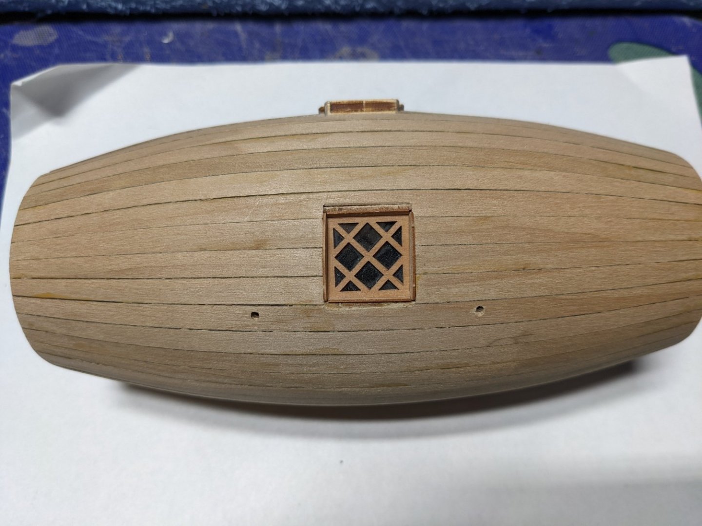


-
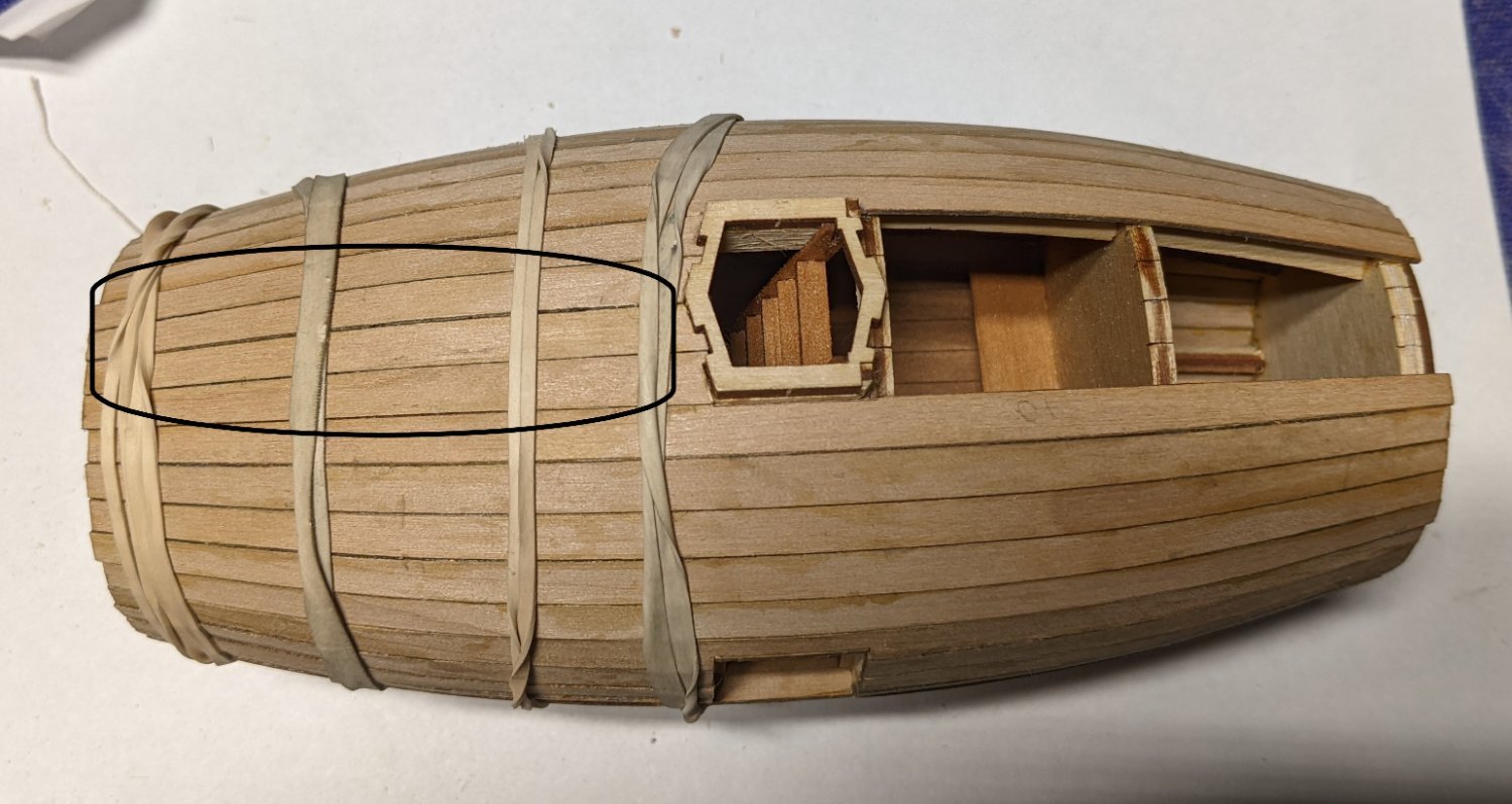
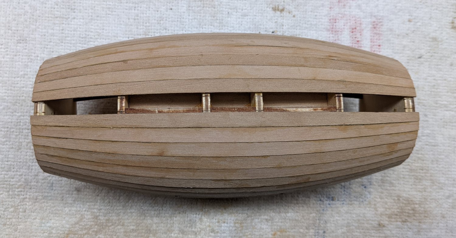
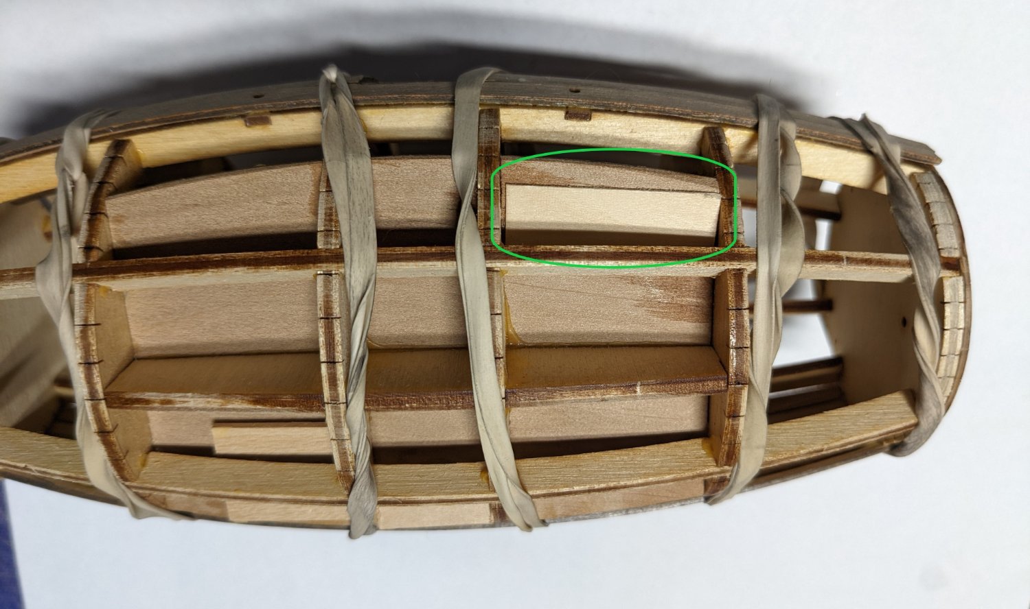
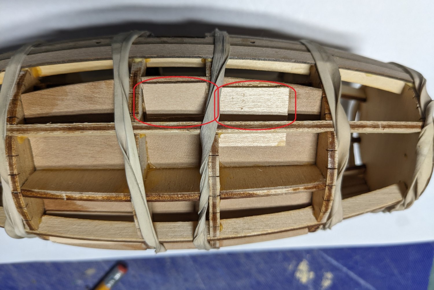
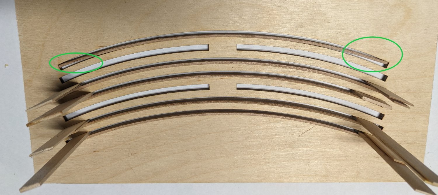
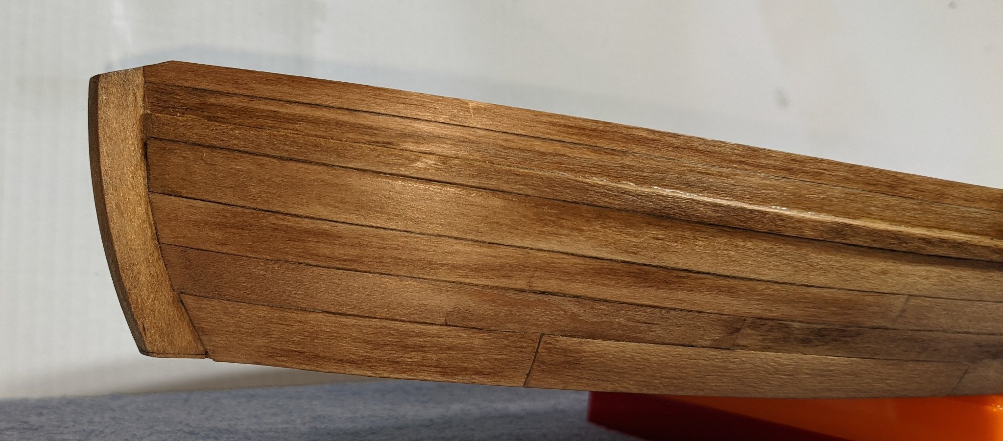
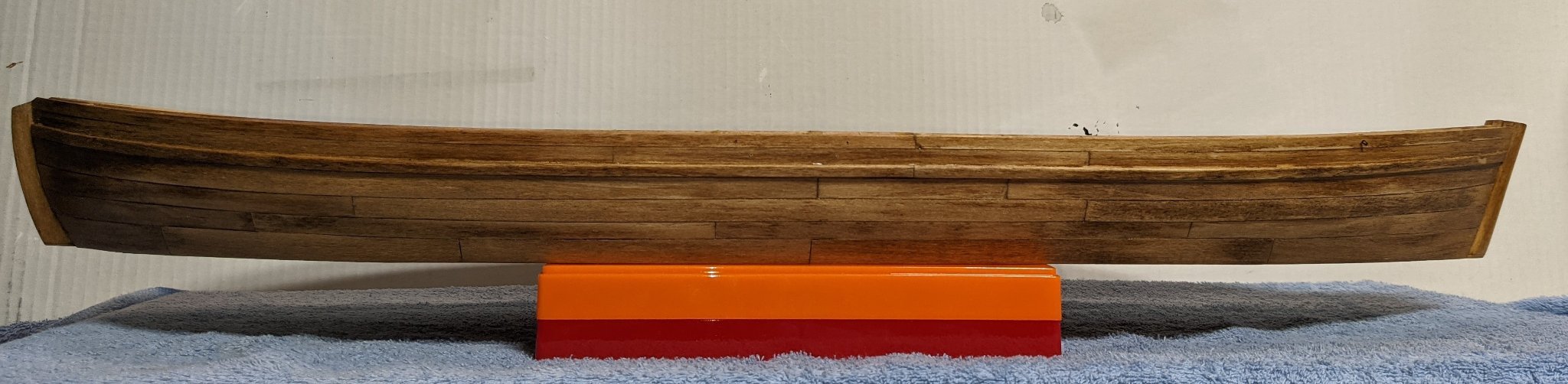
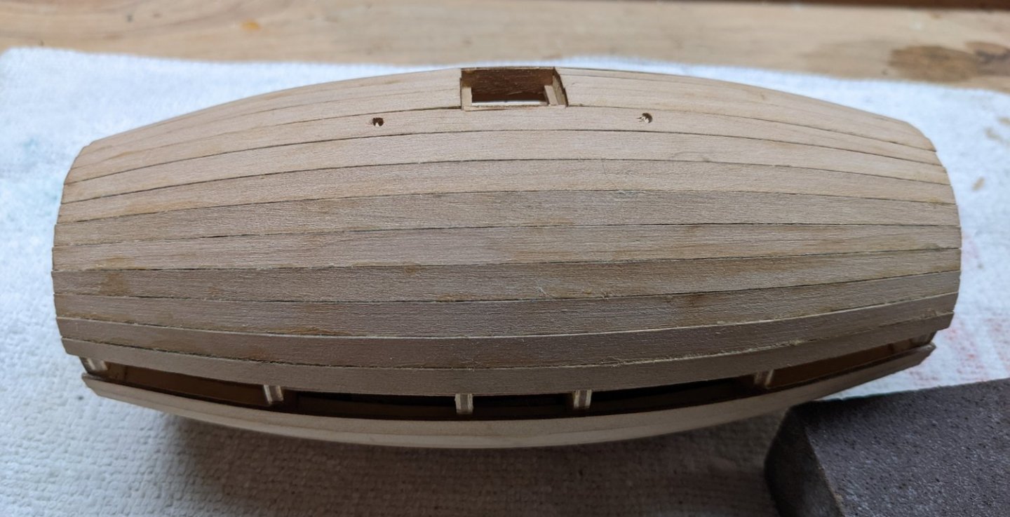
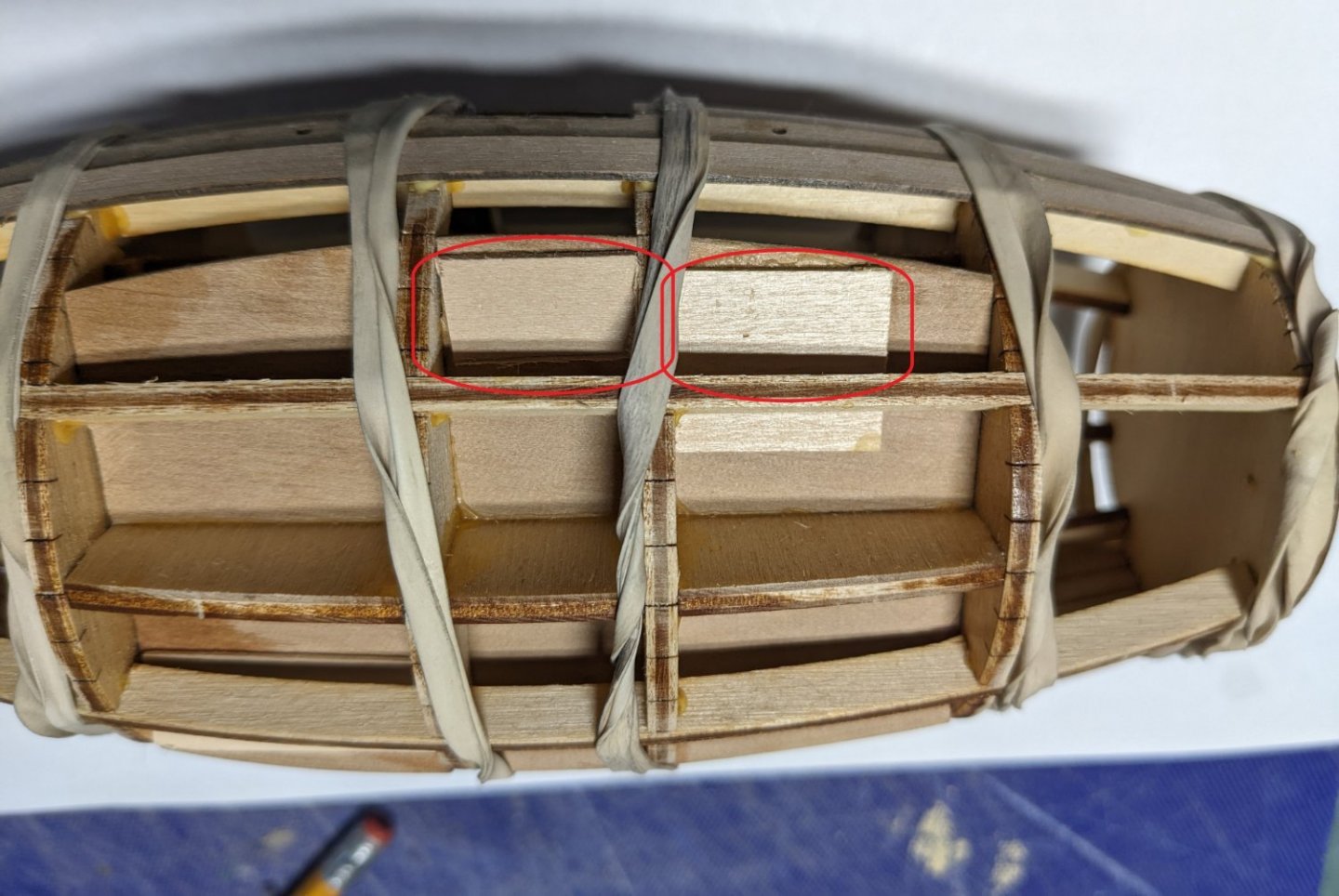
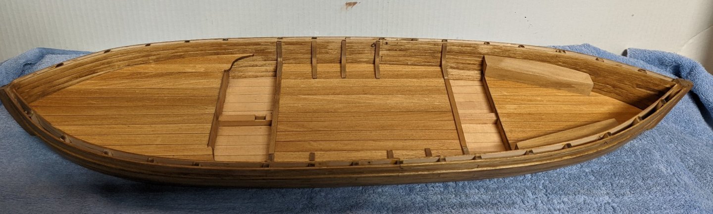
Completed the four stern section 1/2 planks on the top of the hull (highlighted in black). First dry fitted the four 1/2 pieces as I assumed they would not all fit. Since there was a gap at the bottom of the hull, it makes sense there would not be enough room for the last plank on the top of the hull. Since I did not want one skinny plank showing on the top, I sanded down a little of all four planks. End result is not noticeable. I guess the moral of the story here is that early on in the build I did not line up the initial frame planks as exactly as I should have. I strongly suggest you spend some time when installing the initial frames that hold the bulkheads together. If you spend some time on that part you will not end up as I did with a gap on the bottom that had to be filled and some sanding of planks on the top. Would have completed the four bow section 1/2 planks on the top of the hull, but I discovered I inserted two of them in the jig backwards. Thus they were bent the wrong way. The two planks were soaked again and are now back in the jig - hopefully bending the correct way. I am sure I will have the same issue as the stern planks and will have to sand a little of each before inserting into the hull.

- 36 replies
-
- 3
-

-
- Morel
- master korabel
- (and 1 more)
-
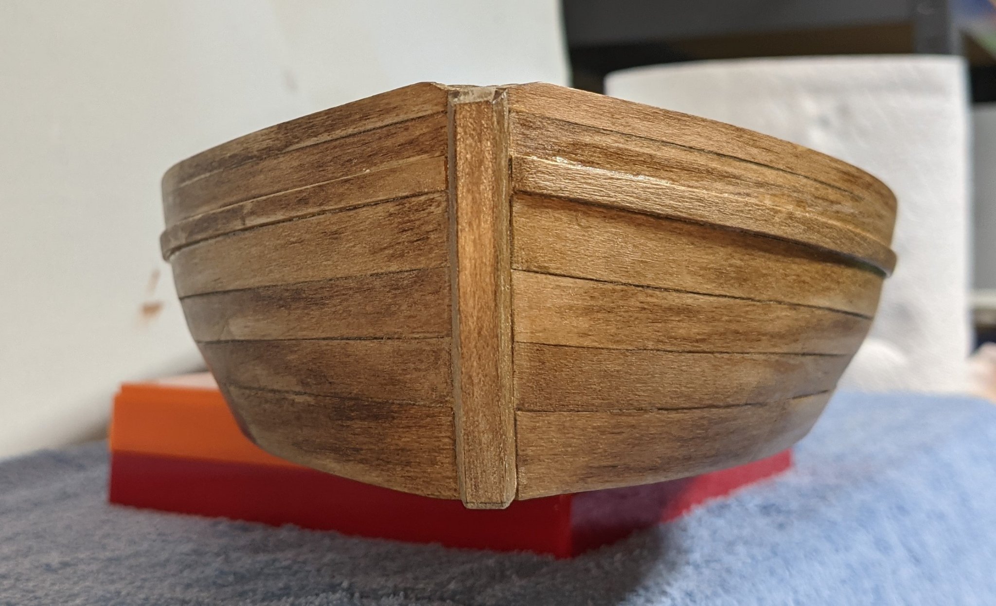
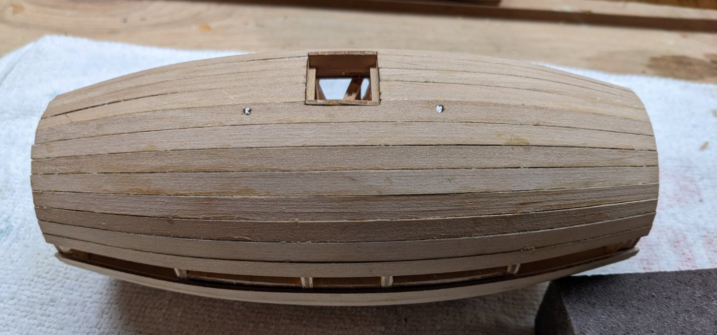
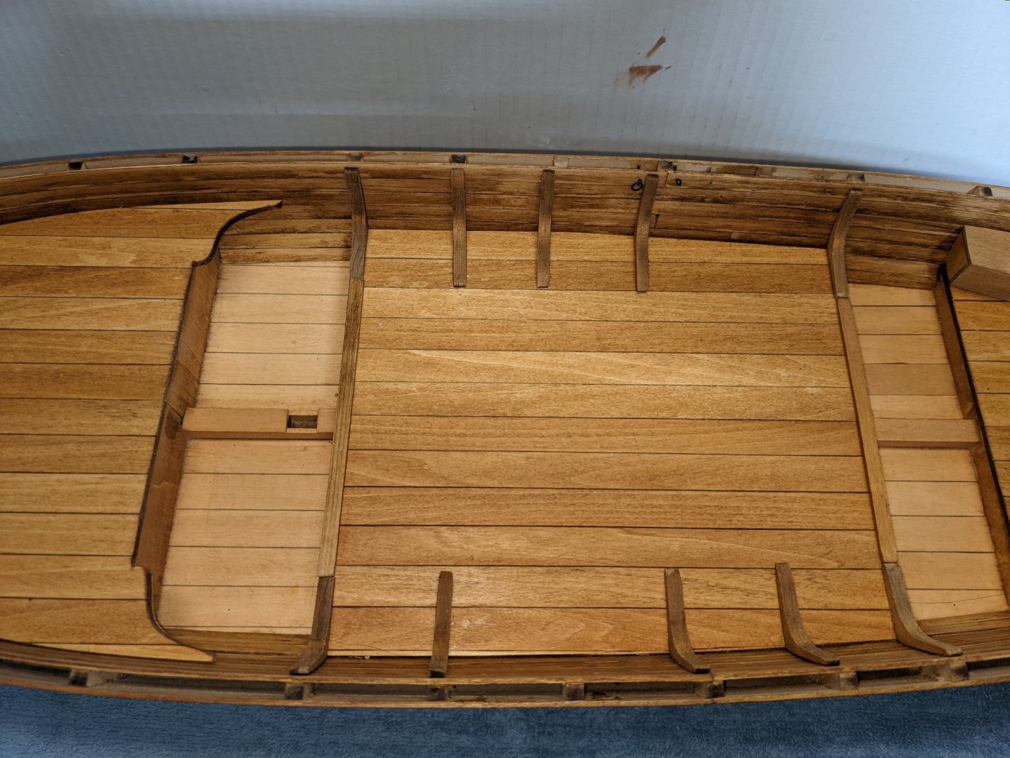
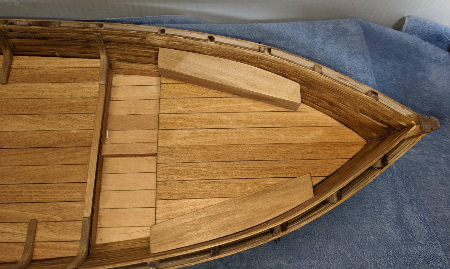
Justin, Thanks for you support. I appreciate it. Moving on with the planking up towards the top hatch. You might have noticed that I have not been planking in the order specified in the instructions. The instructions call to lay a few key planks around each side window and then around the top hatch. After that then fill in the gaps with the other planks. To me that is just asking for a number of small gaps between the planks that will later need to be filled with sawdust putty. As you saw earlier, I started in the middle and worked my way to the bottom with one larger board at the bottom. That to me was a better solution. I used the same approach planking my way up to the top hatch. Stopping with two planks to go on each side before the hatch ( as pictured below). I then could dry fit that last two planks and decide what to if the planks did not fit even with the hatch. In my case, the last to planks fit with only some very minor trimming around the hatch. So I did not have any planking issues as I had on the bottom of the hull. Below show the last two planks around the top hatch with only the smaller side planks to go. Hopefully the smaller side planks will not have any issues. Side windows were assembled earlier in the build, but could not actually be installed until after the planking was complete. I figured this would be a good time to dry fit them and make sure they could get fully inserted into the hull - while I could still get my fingers into the hull. With some minor trimming the windows were fit but will be removed until hull is complete, sanded, and varnished.
- 36 replies
-
- 5
-
-
- Morel
- master korabel
- (and 1 more)
-
HardeeHarHar Thanks for your comments.... Progress is going along rather quickly,,,, and fun too... I decided on this build as I needed a break from the year long marathon builds I have done in the past. Wanted a quick win... And this is defiantly it. Kind of gets me ready for my next marathon already on deck - Chaperon Riverboat.
-
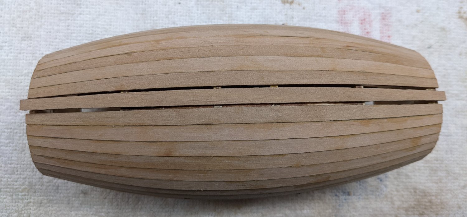
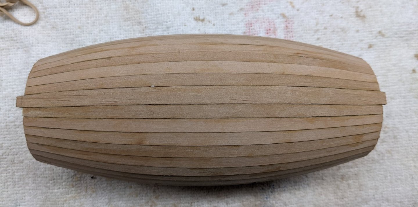
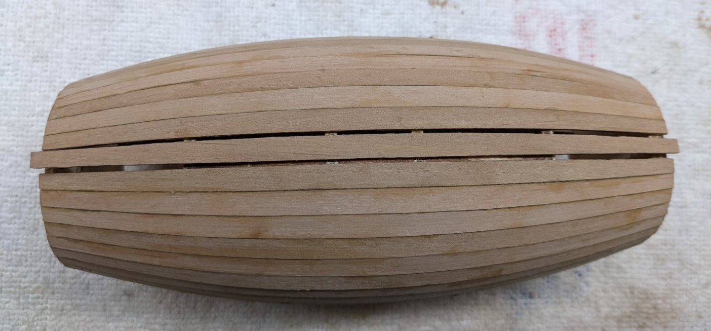
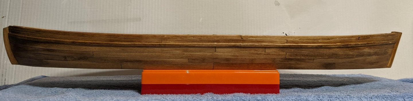
Bottom plank completed... It is a little larger then the other planks but I think it is a better look than trying to fill the gaps with sawdust filler. I was correct in my earlier assessment of my skill.... It did take me two attempts to get it right. As mentioned earlier, there is plenty of spare wood in the left over planking sheets to create a few more planks. Now moving on the complete the planking at the top of the hull. I should have mentioned this earlier, but try to resist the urge to do any sanding until the planking is complete. If you start sanding before the hull is filled in, you will get saw dust into the interior of the hull and that will be hard to get out. In addition, before I do any sanding I will fill in the windows and top hatch with a rag to keep out the sawdust. But as I say,,, that comes later after the planking is complete.
- 36 replies
-
- 1
-
-
- Morel
- master korabel
- (and 1 more)
-
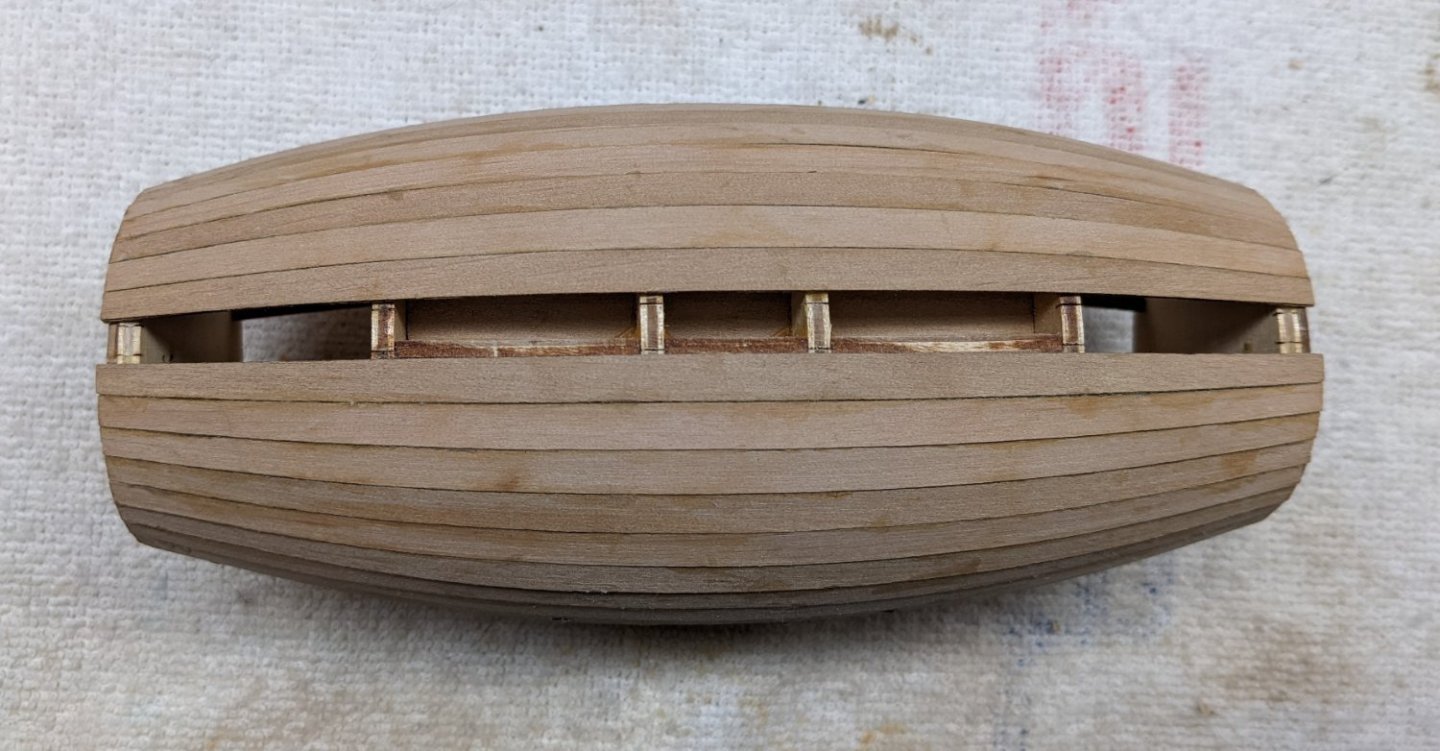
Wlell, Thanks for your comments,,,, As for Model Motor Cars, I learned about it from other modelers. I have not built any of their model cars. I mainly use it as I have with this build - to get very small bolts. It is amazing the really small parts they carry. Planking the bottom half of the hull is almost complete,,,, Port bottom half of the hull Starboard bottom half of the hull Earlier I indicated the planking was very accurate and matched up the lines exactly on the bulkheads. As the planking when on there actually was a few deviations in the planking to where some did not really match up with the bulkhead lines. One option is to stay with the bulkhead markings and later fill with sawdust putty. Other is to continue the planking without gaps and "fix" the issue at the last plank - on the bottom of the hull. I choose this 2nd option. To me one larger gap at the bottom is better than having several planks on the hull with Sawdust filler. Note below the gap for the last plank is a little larger than the last plank. At this time, the easy (and maybe smart) option is to just lay the plank in the middle of the gap and then fill both sided of the plank with sawdust putty. After all, this is the plank on the bottom of the hull, and when the model is mounted, no-one will see the filler. But what would be the fun in that? After all "why do something easy when you can make it hard." I decided to make a custom plank that will completely fill the gap. This plank will be a little larger than the other planks, but there will not be the sawdust putty filler. Take your choice as to how to fill this gap. To me a little larger plank (on the bottom of the hull) is the way to go. There is plenty of extra wood from what remains of the planking sheets to form several planks if needed. At my skill level, it may take me a couple attempts to get it right. Will show the result of my attempt after I complete the plank
- 36 replies
-
- 1
-
-
- Morel
- master korabel
- (and 1 more)
-
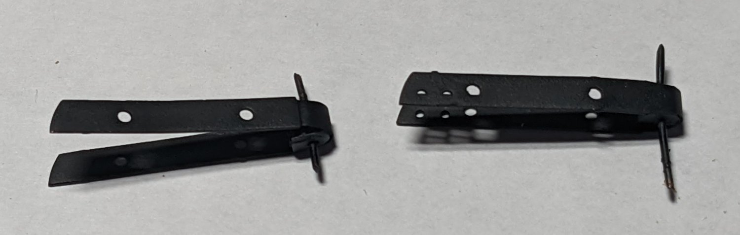
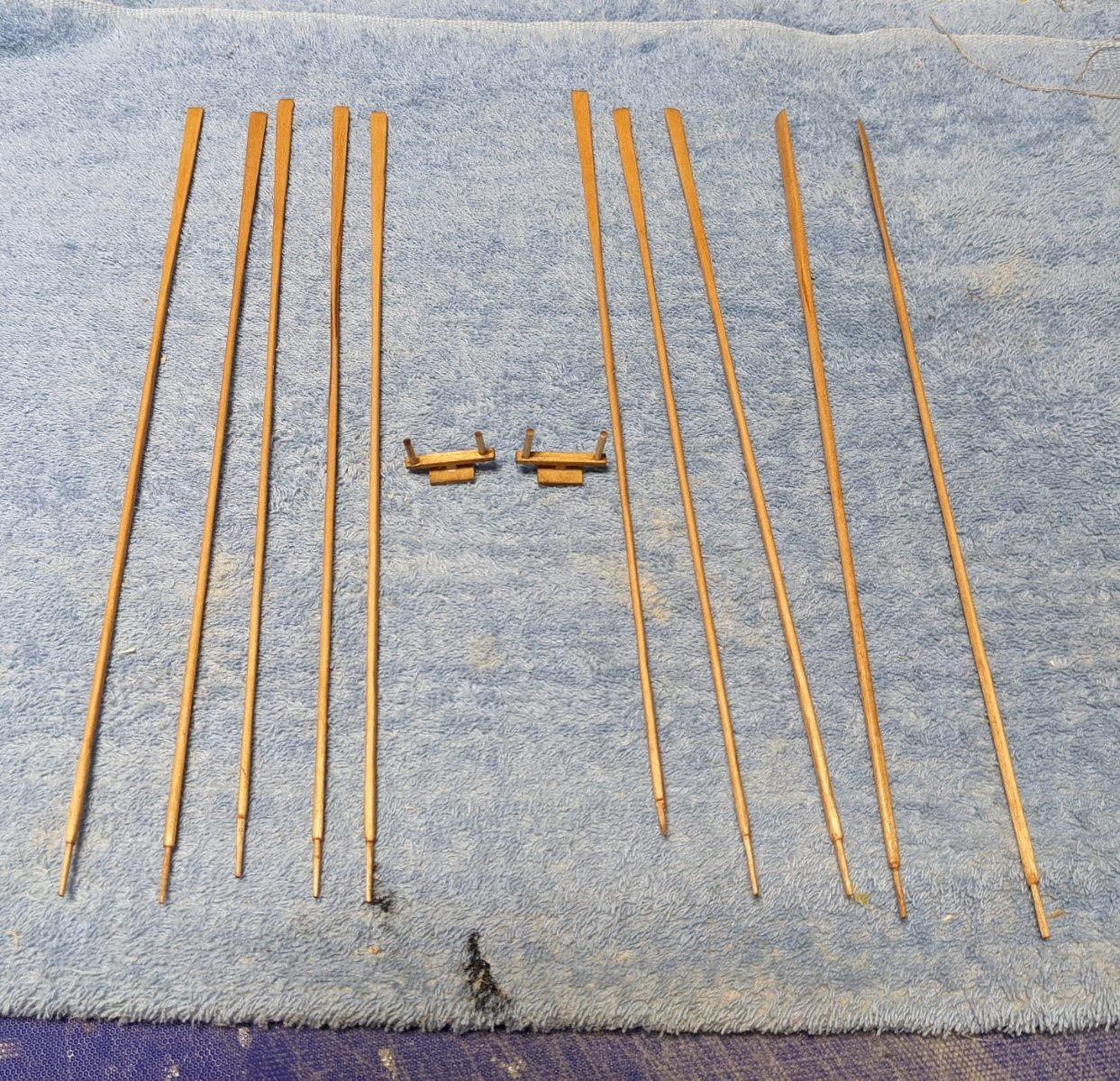
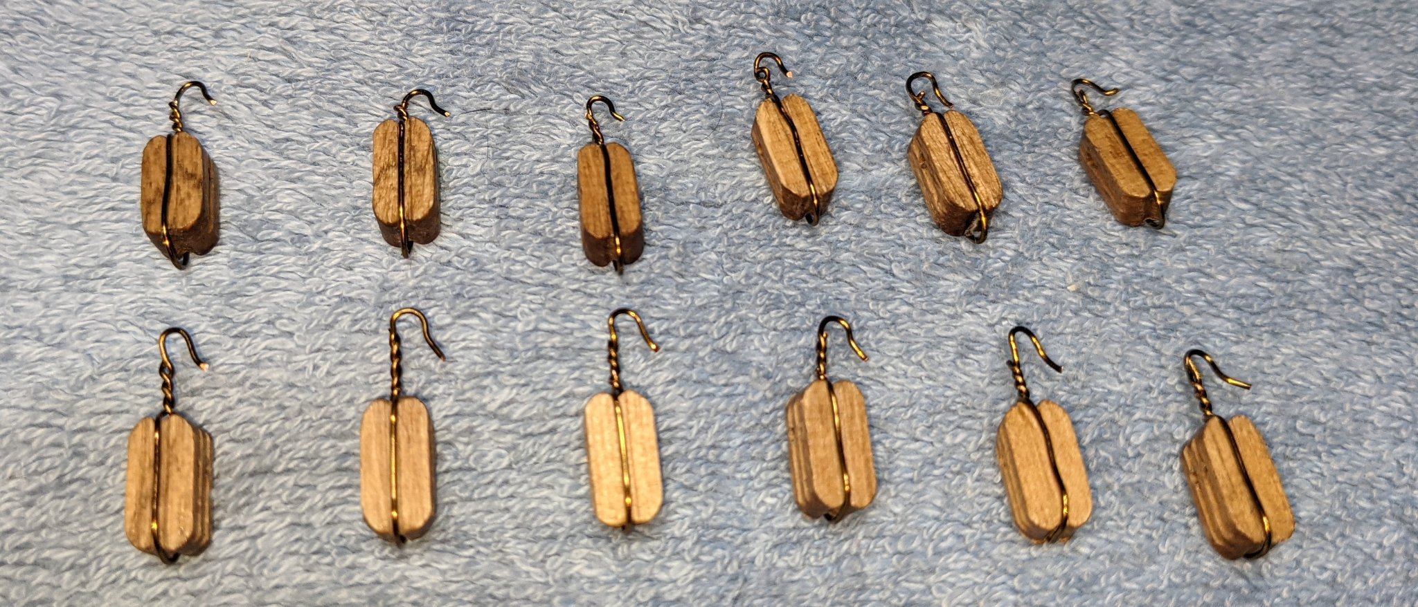
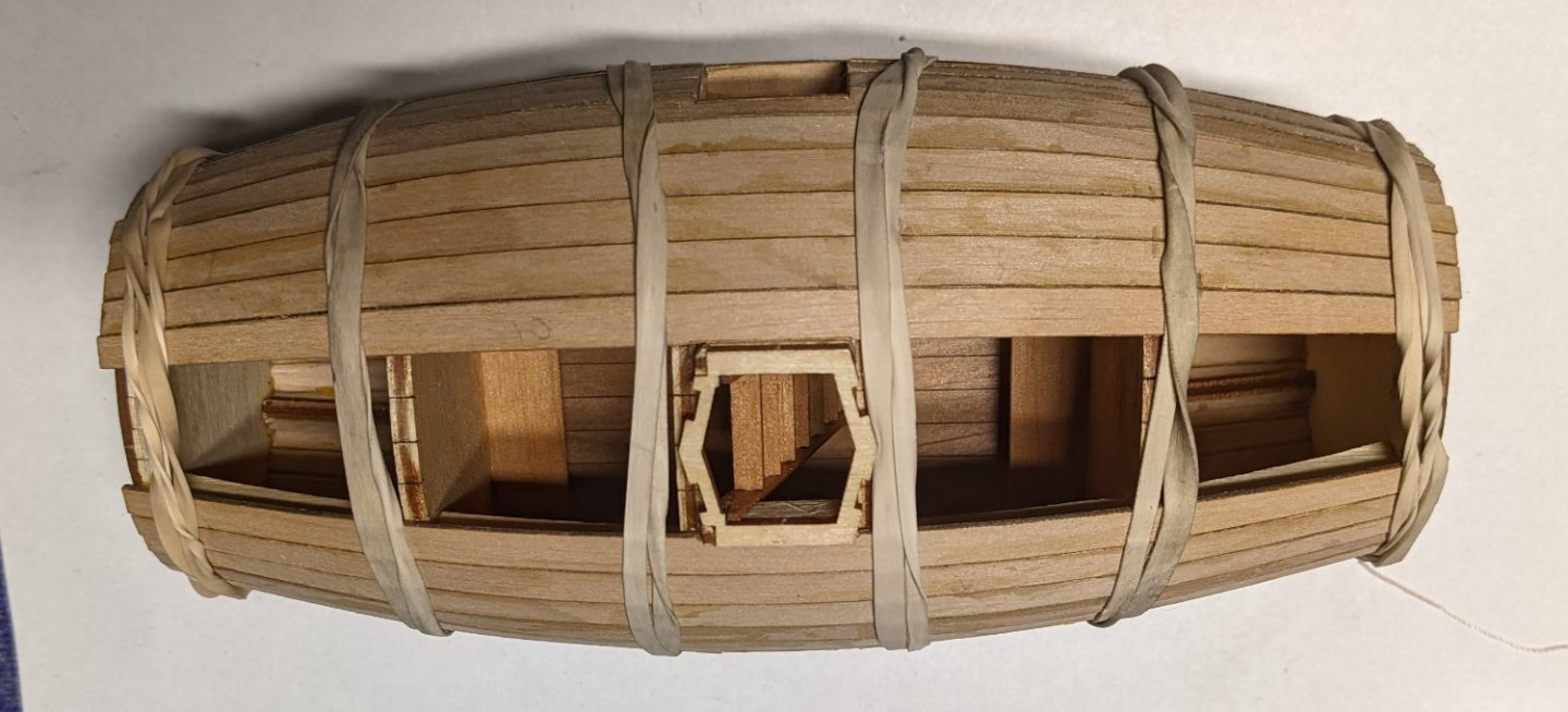
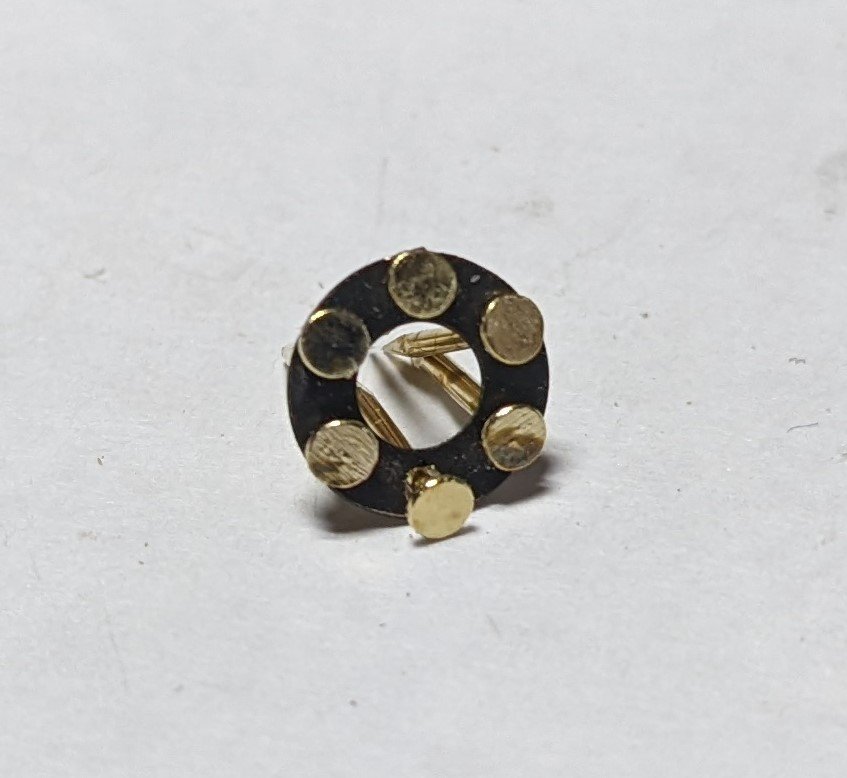
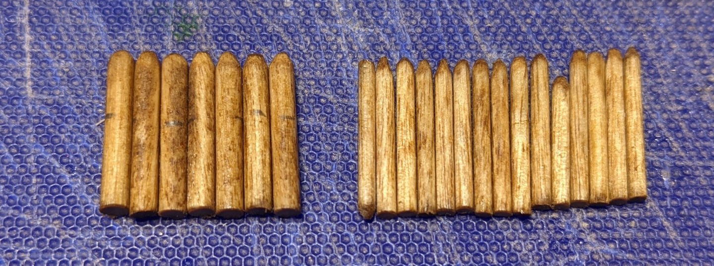
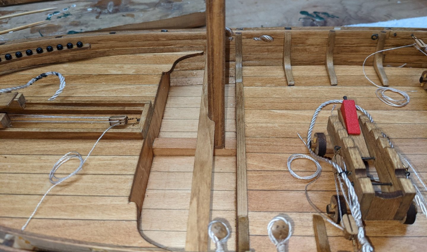
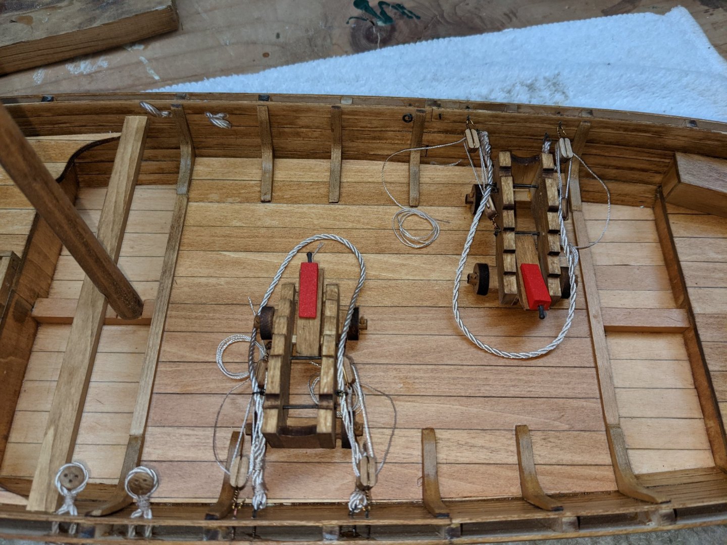
Going with supreme overkill, I made a slight adjustment to the jig used to bend the planks. Again this is totally uncalled for and way overkill as the jig works great as it is, but it was easy to do and I think it helped getting a better bend. Note in the picture below the top plank in the bender as intended. Note the plank ends (in green) do not follow the curve exactly. By inserting a spare 1/16 scrap piece of planking at each end of the jig, as shown the other planks, allows for a smoother curve. Just put the wet plank into the jig and then insert the 1/16 scrap piece of planking at each end until dry. Repeat for each plank that is to be bent. Again,,, really overkill and not really required.. Continued on with other stuff as the planking continued. Inserted the plugs (shown earlier) into the fiery tubes. They are really to install. Completed the rudder hinges. Glued the insert (mentioned in earlier update) and ready for installation on the rudder. The wire shown in the picture is temporary and just to help with alignment. One thing I should have mentioned earlier is that until the flooring is covered with the planking, it is very vulnerable to breakage. Working with the planking required a lot of adjustment getting the planks lined up correctly and rubber bands attached. Easy to forget the flooring is exposed and easily broken. In my case it was only cracked and did not break into two pieces. A simple patch below the broken flooring did the trick and is not noticeable. Did I mention the flooring was really easy to break? Two more later breakages where patches were required. I might suggest before you start the planking to support the under edge section of the flooring all around the floor. Will be hidden but could save you some tears during planking... Started looking at the supplied nails intended simulate bolts. They are OK for bolts around the hatch and windows, but are way too big around the oars, ballast, and steering lines. Below shows what the supplied nails would look like around one of the oar fittings. It overwhelms the fitting. I had some left over 1.6mm and 1.2mm bolts from other builds and they seemed to fit much better. Unfortunately the ones I had on hand were chrome would not look correct. I ordered some 1.6mm and 1.2mm brass bolts from Model Motercars that should show up next week.


- 36 replies
-
- 3
-
-
- Morel
- master korabel
- (and 1 more)
-
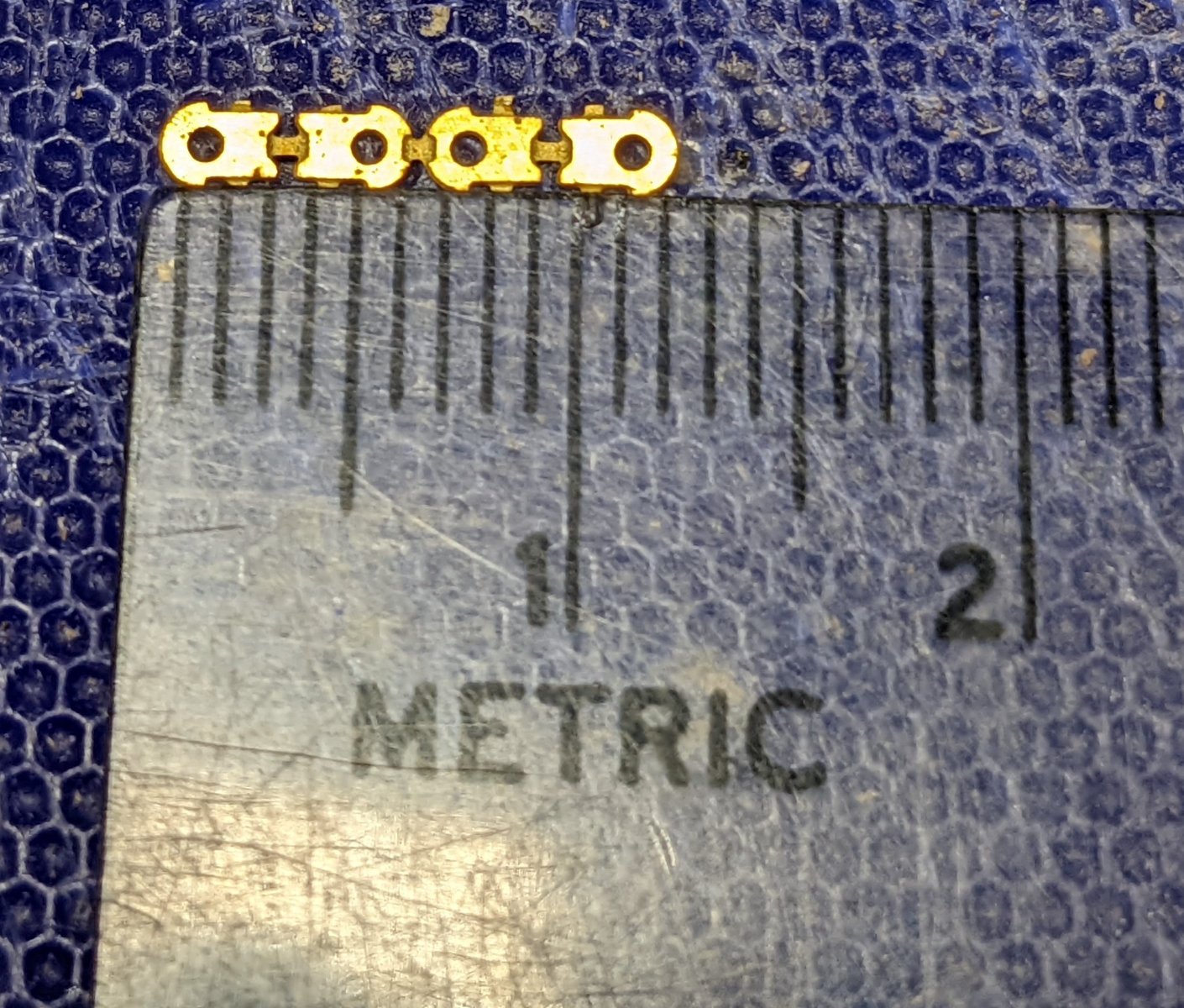
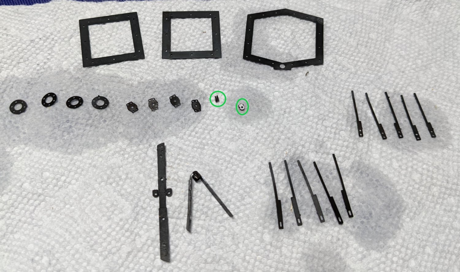
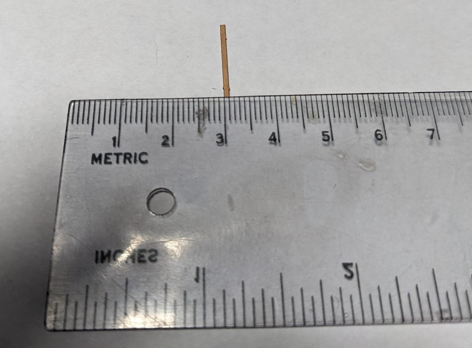
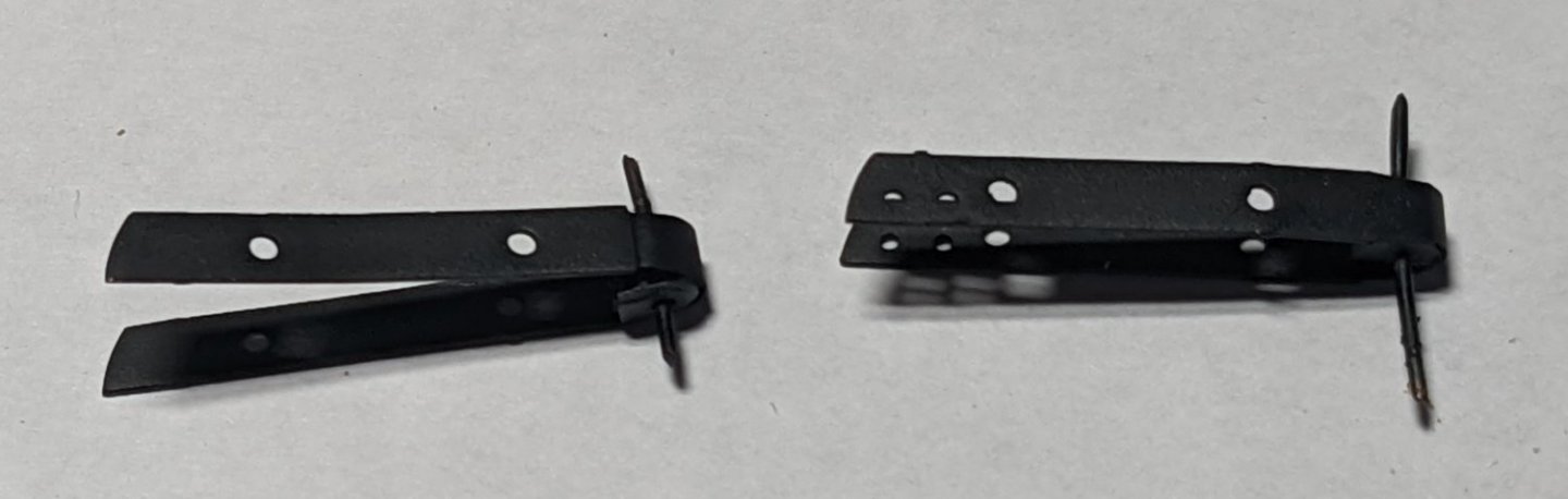
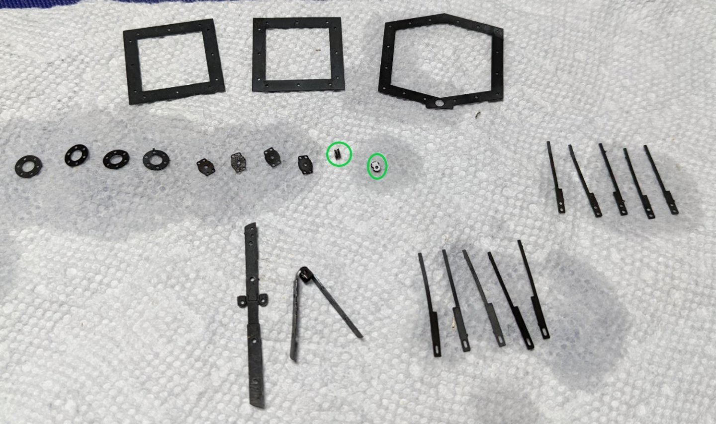
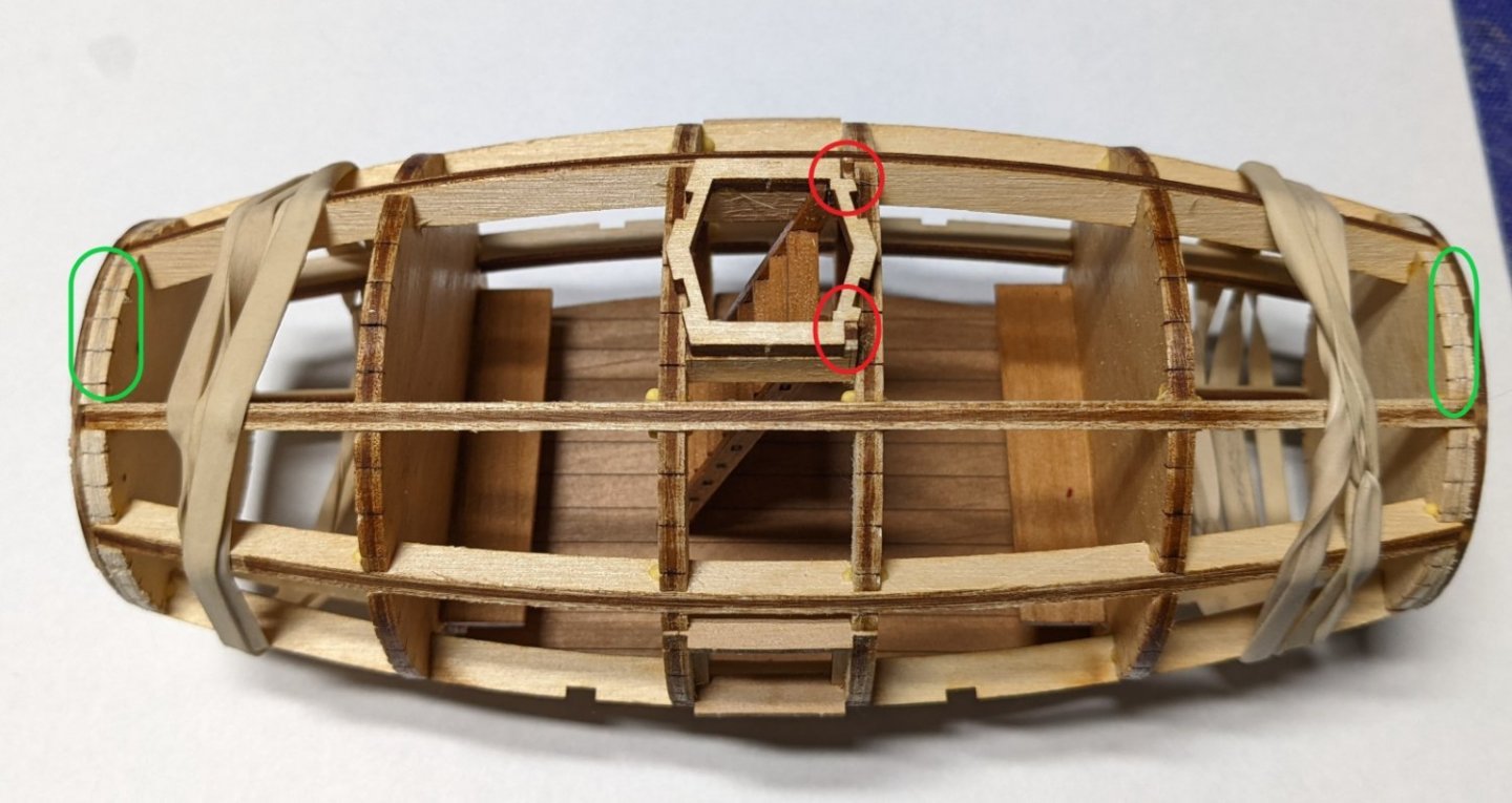
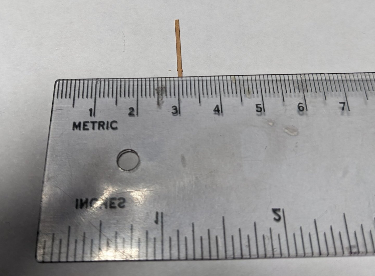
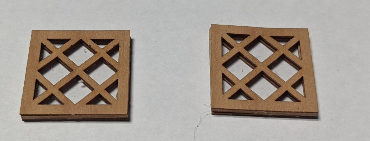
While the planks were drying I starting working on the etched brass sheets. Like some of the wooden parts,,,,, some of these brass parts are really small. Do to the size, it takes some time to cut out each part, trim off the nubs, and somehow keep from loosing any.. Somehow all seems to have survived the trimming. On to blackening,,,, There are about as many theories on blacking brass as there are modelers... Everyone has their favorite. I use Novacan Black Patina. It is something folks who make stained glass windows use to blacken the lead between the glass. I have found it works great on brass at 1/2 strength. Below is the result. The two green circles show the above brass part that gets folded four time to form the two rudder hinges. Needless to say,,,, a pair of very sharp tweezers are in order here. I should have included a ruler in the picture. Picture just does not do justice on just how small and fragile each part really is. First section of window planking is complete. I wanted to start out slow as I was not sure just how accurate planking was. I figured around the window was a good place to test out the accuracy of the planking. I have to say, all the planks were right on the marks. It really was easy. Planking should speed up at this point now that I know planking is accurate. Never had a model before where planking did not require a lot of sweat and occasional nasty words. Hopefully I have not spoken too soon and the rest of the planking will be uneventful.

- 36 replies
-
- 5
-
-
- Morel
- master korabel
- (and 1 more)
-
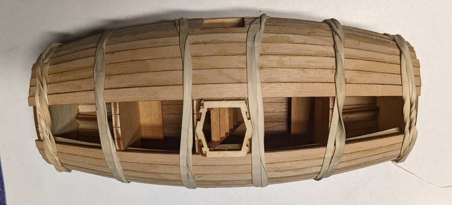
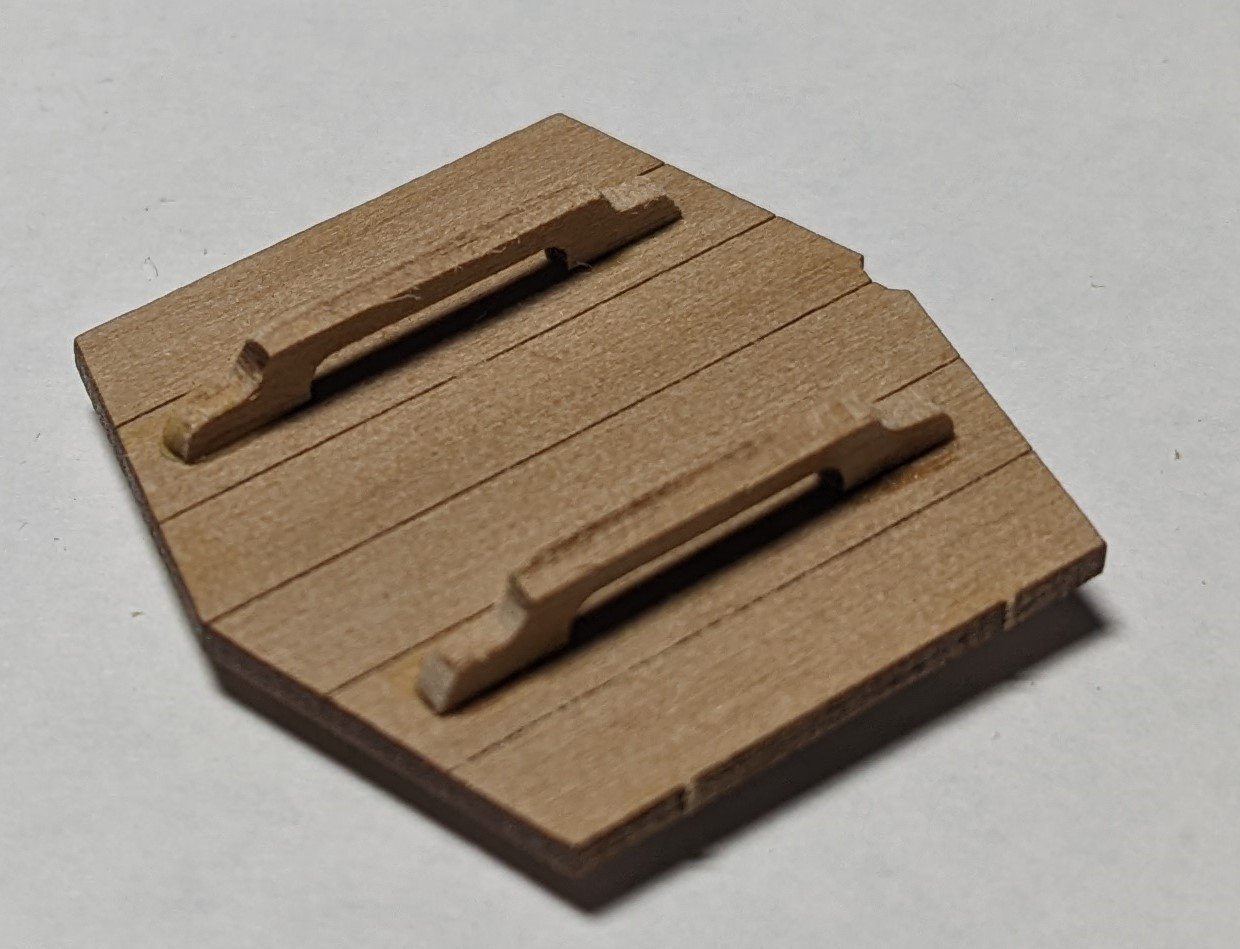
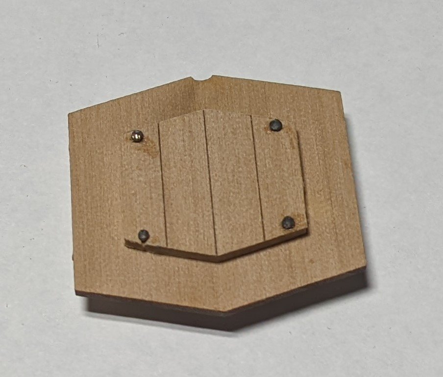
Began soaking the planks in the supplied jig... I have to admit, that seems like a pretty neat idea since the hull is so symmetrical. No spiling and shaping is necessary. I am sure I will end up having some "adjustments" but with each plank being so similar the the location of each plank is marked on the bulkheads, this hopefully will be an easy and fun planking.... I know is the past, at my skill level anyway, the words "easy" and "fun" were never seen in the same sentence with "planking". While my planks were socking and drying in the jig I worked on a few other items.. For the cabin lid, it is the same drill as with the fore and aft frames to where you glue the two halves together. Again they suggest using four wires to line up the holes. I did that, but as I said above, it seems it would be much easier just to eyeball the four holes and then insure the inner lid was centered on the outer lid. Here is where I got a little lost,,,, On the outer lid, the handles will cover up the holes, but on the inner lid the holes remain. I assume they would want you to fill the holes with filler. Instead, I just took some old pins and stuck them in the holes. Kind of look like bolts. You decide what you want to do,,, wood fuller or bolts. Pins inserted from the lower lid temporarily sticking out the top. Looking at the lower lid after the pins have been trimmed. Final view of outer lid Started work on the paddles... Using a file they trimmed up OK The inner edges of each plank was beveled before soaking. Instructions did not mention it, but with other ships I have built there is always caulking between the planks. Caulk lines are not shown on the finished model, but what ship of this era did not have caulk lines? Thus, right or wrong, I used the "side of the pencil" process to blacken the side of each plank. First plank applied,,, Hopefully will be able to apply more than one plank a day, but I wanted to start out slow around the windows as I am not sure how precise the planks will be. Ideally I would like to be able to have a little filler as possible,,, so minimum gaps if possible


- 36 replies
-
- 4
-
-
- Morel
- master korabel
- (and 1 more)
-
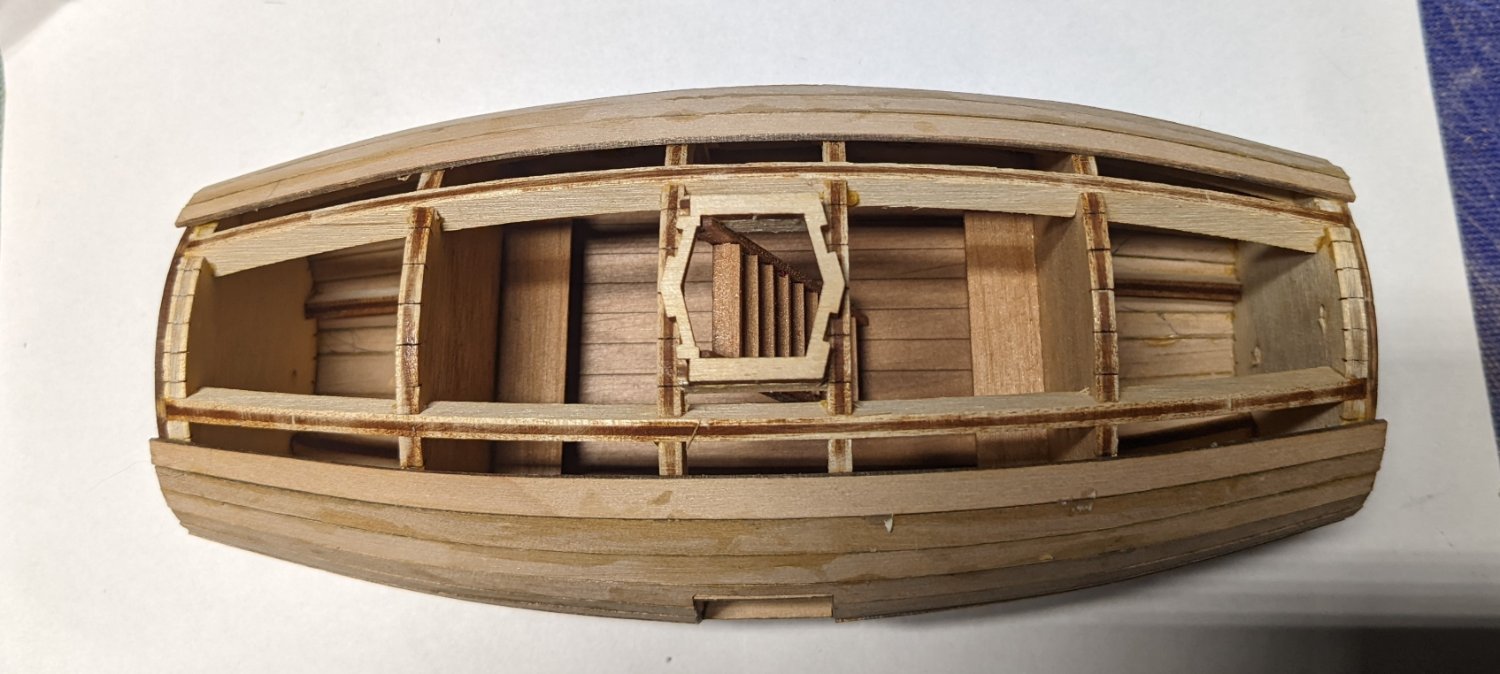
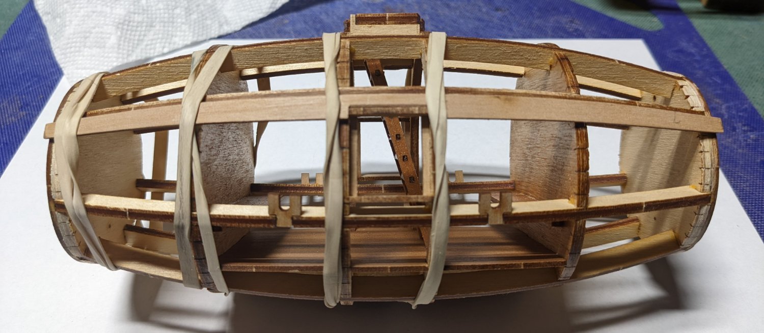
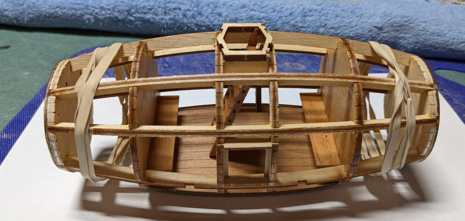
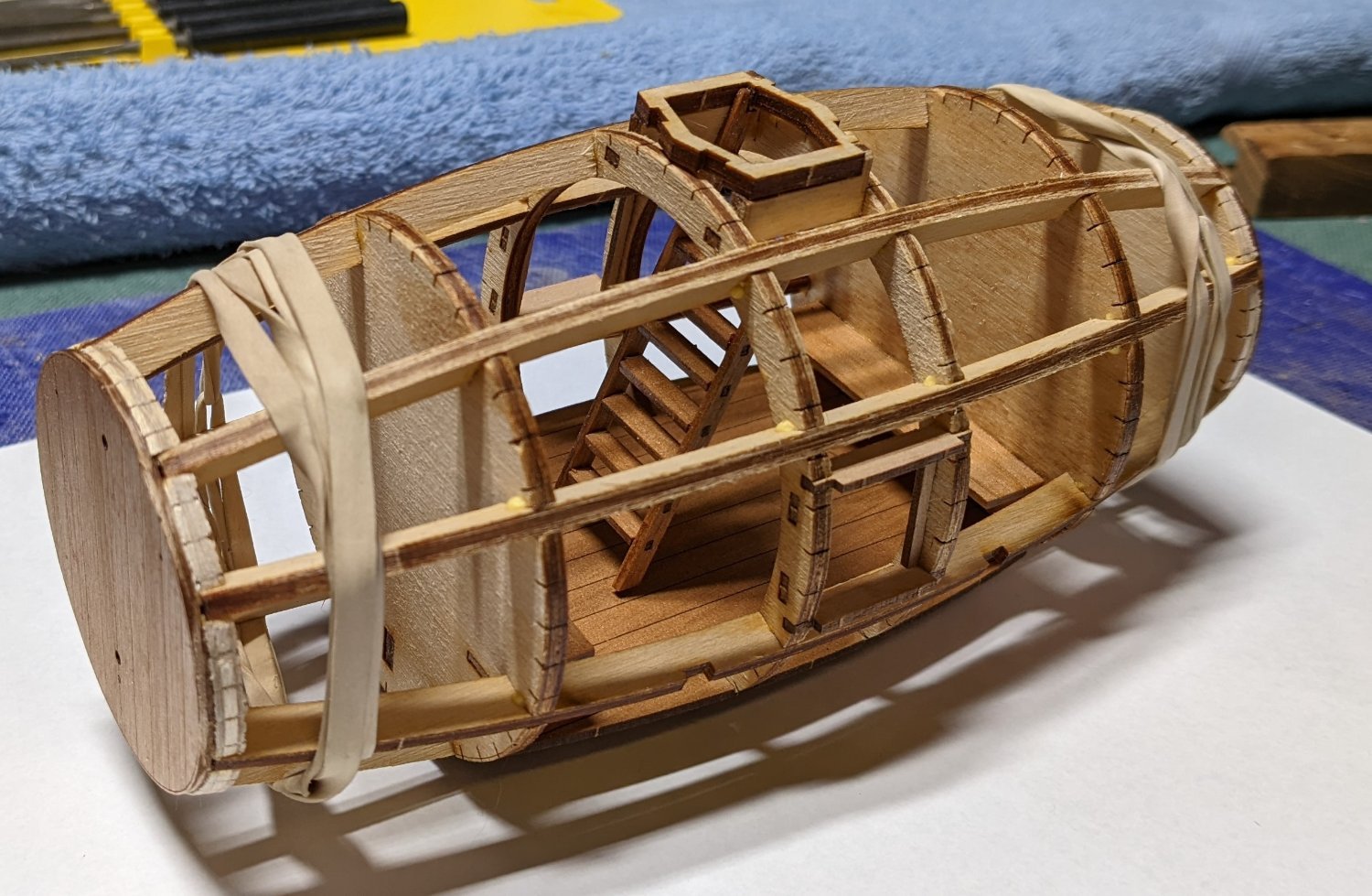
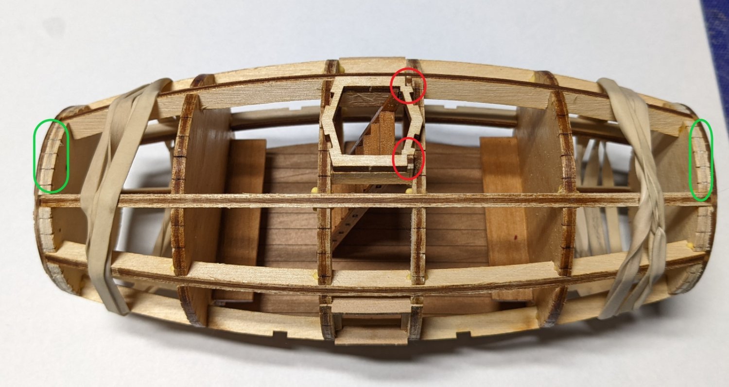
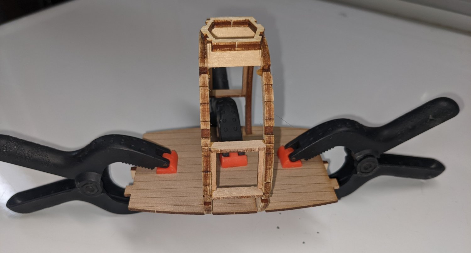
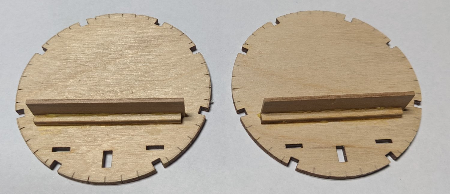
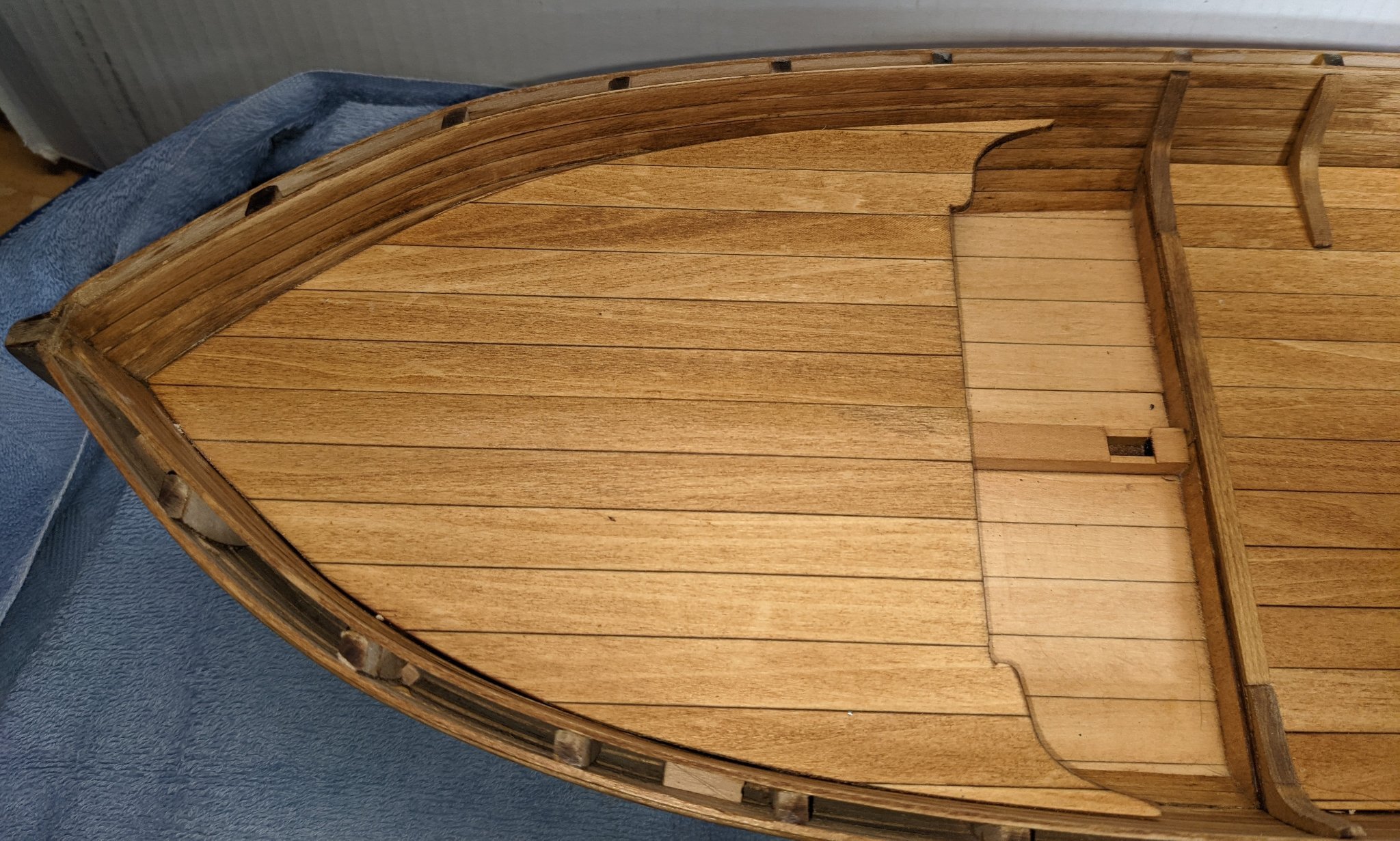
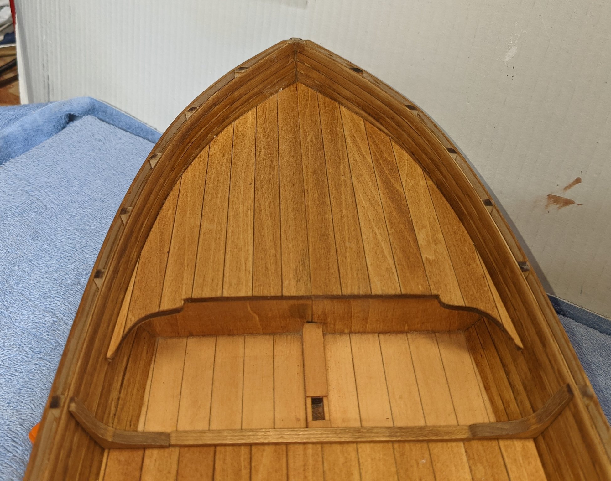
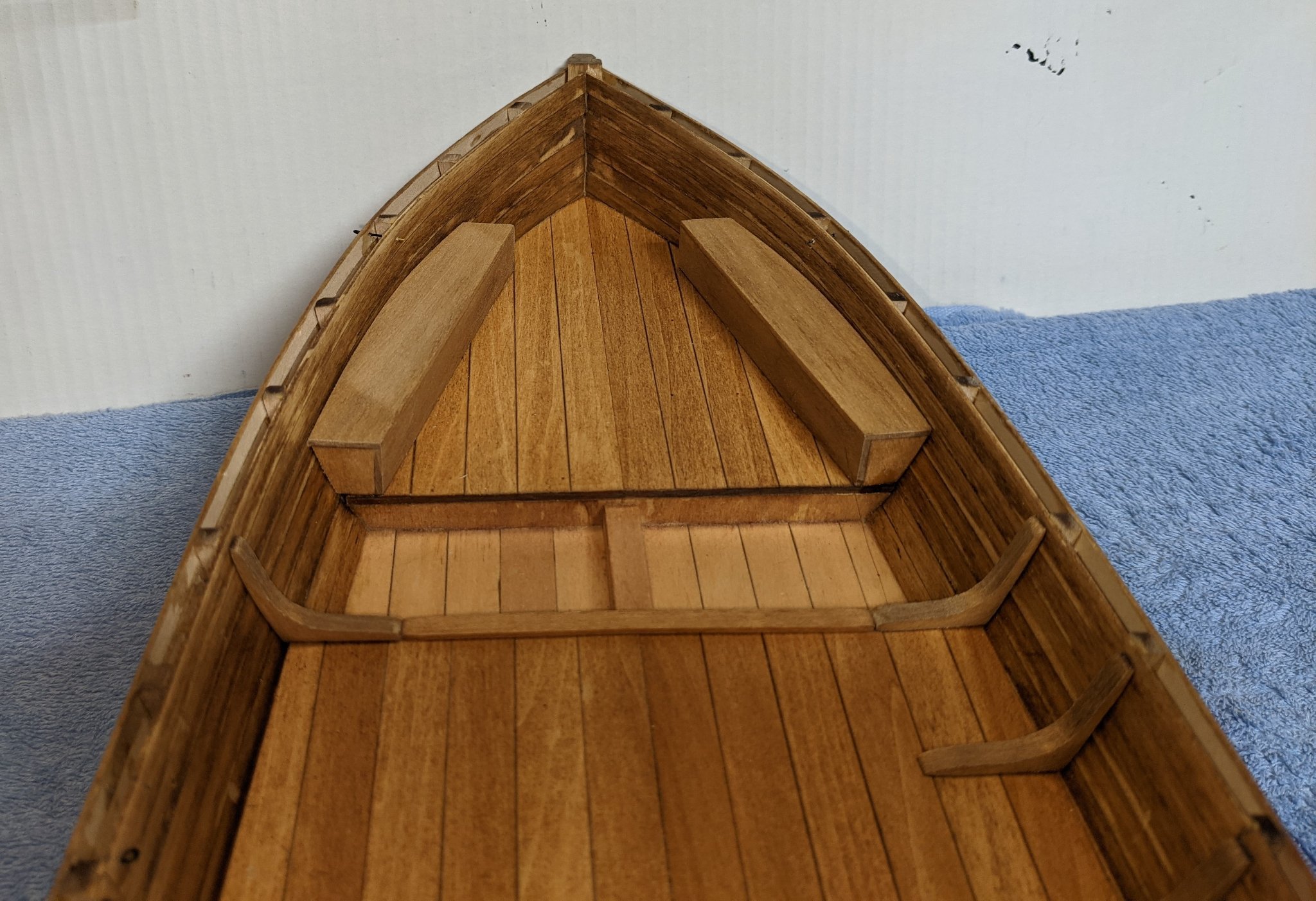
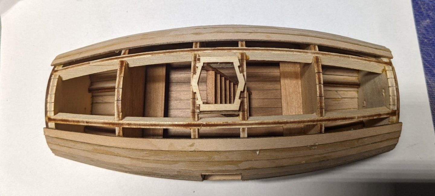
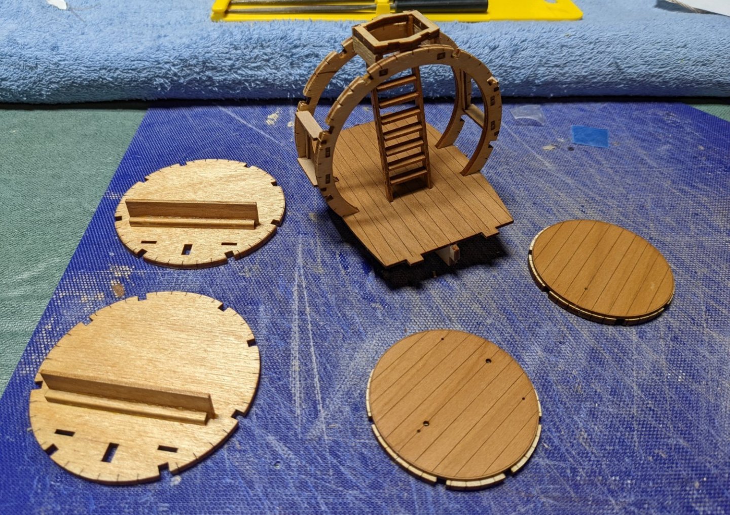
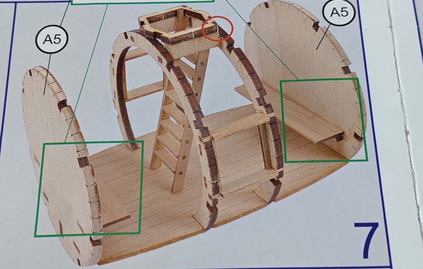
Next come mounting the stairs in the model. Instructions say in bold print to not mount the stairway in the wrong direction. It should be mounted toward the bow of the boat. Problem is, at this stage it is not really apparent which direction is the bow or stern. They supply the following photo. No explanation, but there is a red circle on the top of the hatch support. It points out on one side of the support there are little notches... Looking at the way they have the ladder mounted, I can only assume the notched part of the hatch structure points to the bow The aft fore frames are made up of two circular pieces. In order to get the pieces glued in the correct position, they suggest using the supplied wire temporally through the holes to line up the pieces. Turns out the holes are too small for the thinnest wire supplied in the kit. Rather then expand the holes, I had some 22 gage wire so I used that instead. I am not really sure the wire is necessary. One could just by sight line up the holes. Even using the wires, you still have to line of the outer (smaller) disk in the middle of the larger disk, so the wires are not a true indicator of correct position. Below shows my use of the wires to line up the holes.... Again,, I think that was somewhat of a waste of time. As I mentioned above, note the inner disk is larger than the outer disk. The list line of this sections says "After the glue is dry, handle the edges of the frames in draft following the engraved lines". Something was defiantly lost in the translation to English. What that really means in bevel the large inner ring to better accept the planking that will eventually run the length of the hull. After a few coats of rub-on poly we are ready to start the assembly, I ran a file quickly over each opening in each frame,,,, just to make the fit a little easier. Basically each frame went into place with only a little bit of "persuasion". Once it place it was very solid. Below is a picture showing the final assemble hull. The red circles show the notches on the hatch structure the depict the bow section. The circles in green show the inner disk that has been beveled. It is no longer larger than the outer ring and the angle is similar to the angle of the frame going into the end pieces. And a few more final shots of the progress


- 36 replies
-
- 8
-
-
- Morel
- master korabel
- (and 1 more)
-
Yvesvidal, I like the rope on the 3D print technology model..... I may consider that, when I get to that point....
- 36 replies
-
- 2
-
-
- Morel
- master korabel
- (and 1 more)
-
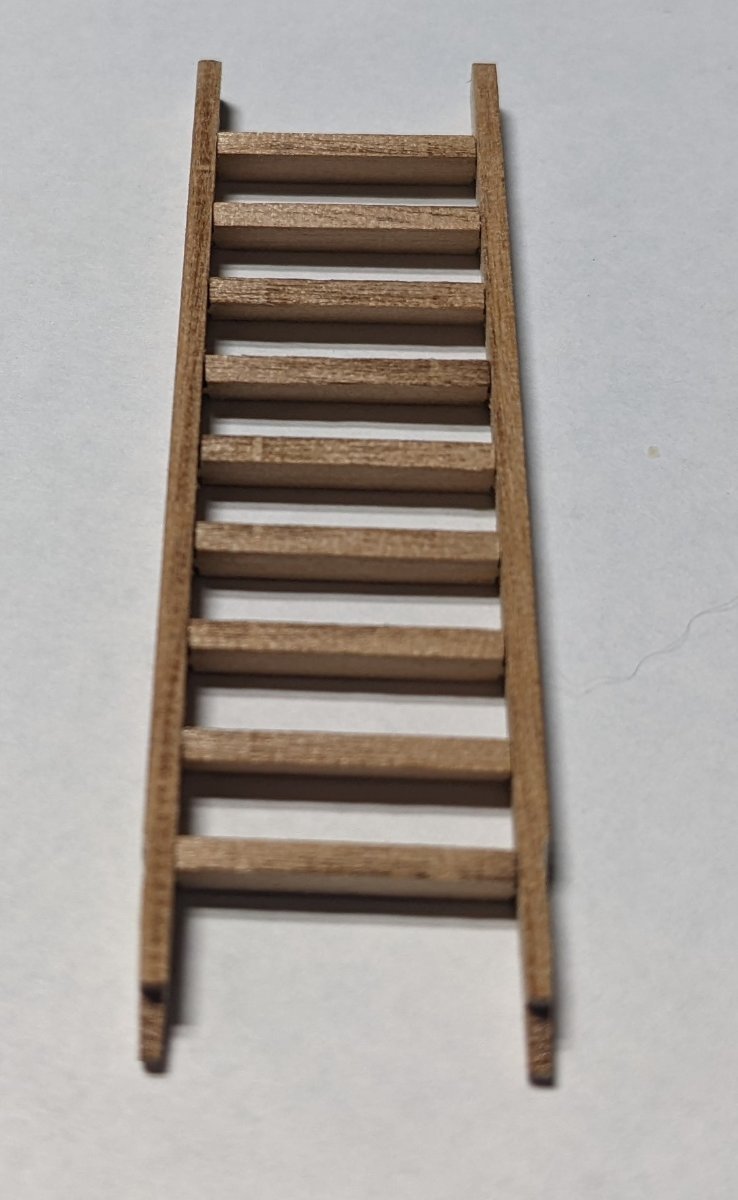
The center part of the hull construction goes pretty straight forward. Parts all fit together very well (surprisingly well). Instructions call to bevel the upper and lower jambs and the cabin frame walls following the engraved lines on these parts. It also cautions not to over bevel. I assume this is done to provide a better gluing base for later planking or parts. Problem is the bevel line is so small (about the thickness of a hair) that about all it would take is one swipe with a sanding stick. To me not really work the effort of over beveling, so I skipped the beveling at this time. I assume (hope) there will be time later in the build when the planks are installed to bevel if really needed. At that time I would then know the exact amount of beveling to do. Next it was on to the lower port and starboard windows sashes. Here is where the parts get really small. There are four very small pieces that frame each window sash. Two pairs for small tweezers are defiantly in play here. Not sure how these were etched into the wood sheet without burning the part. Did I say before that these sash border parts are really small ? 🙂 After gluing the four small pieces around the border of each sash there will be some trimming of the acrylic that will be between the two sash pieces of each window. When putting in the acrylic be sure you have clean hands. Acrylic smudges easily. With a little patience the window ended up OK, In the category of "do as I say and not as I do".... the windows are made of four very small borders (shown above) that hold in the acrylic sandwiched between the two sashes. If you plan to stain or put poly on the model, apply it on before you assemble the sashes. In my case I did not do that so I had to get a small paint brush and paint on the poly being careful not to get on the acrylic. Would have been much easier had I applied the poly before I assembled the sashes. Stairway is next,,,, again no big deal as the parts all fit great. Be sure to practice how you are going to insert the rungs before you actually start gluing them in. Main issue here is keeping previous rungs in the stairway as you add each new rung. This take a little patience here too, but if you go slow all the rungs will go into place.. Next come the two seats into the center part of the hull. Pieces just fall into place - no big deal


- 36 replies
-
- 5
-
-
- Morel
- master korabel
- (and 1 more)
-
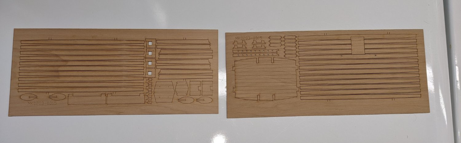
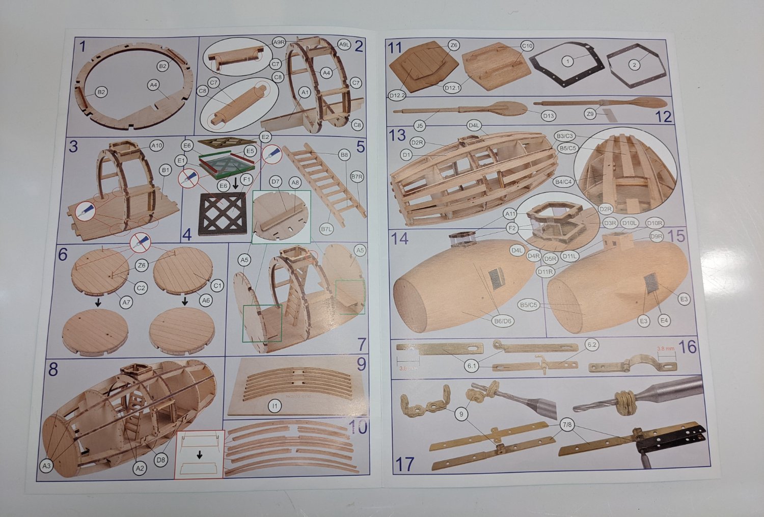
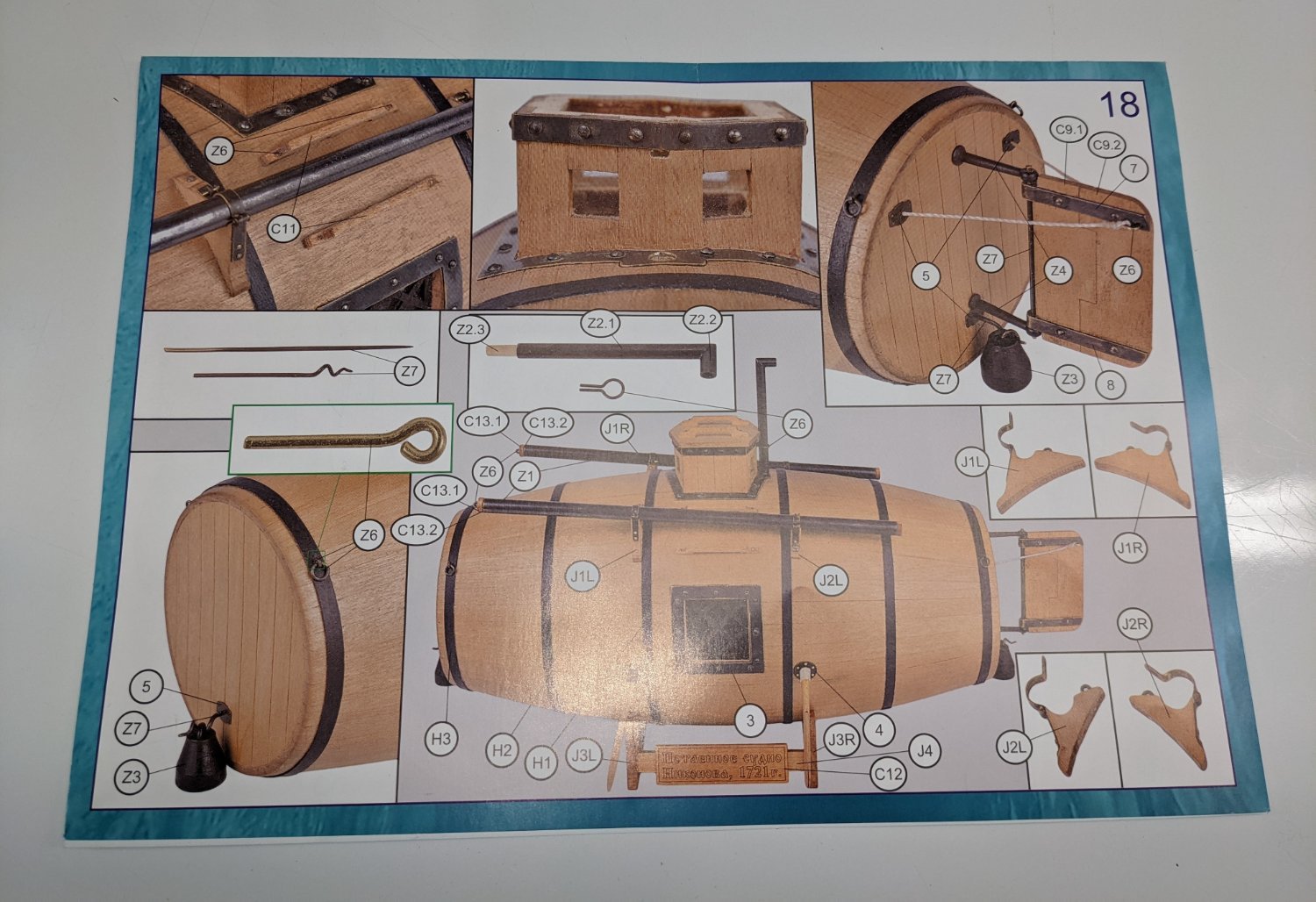
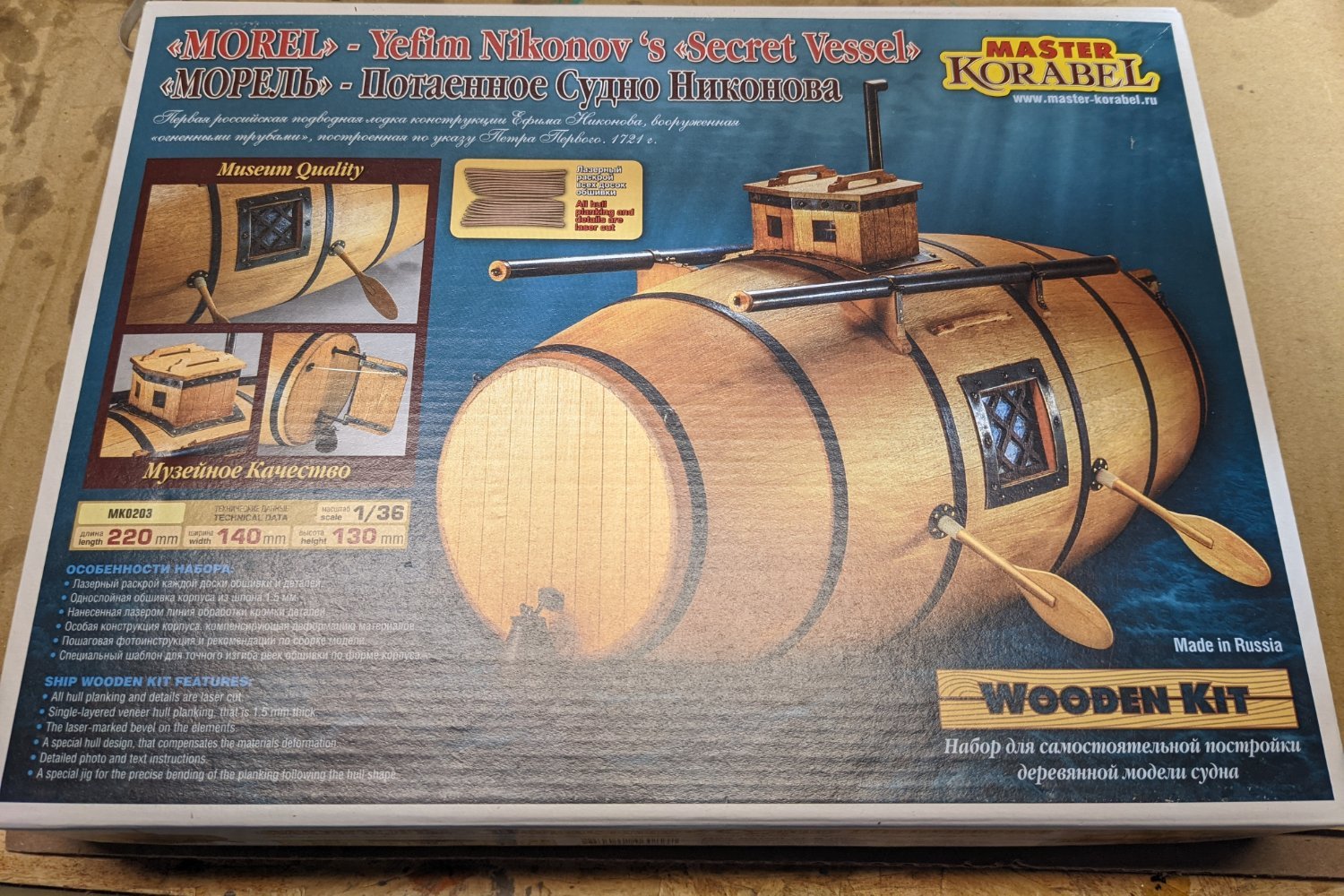
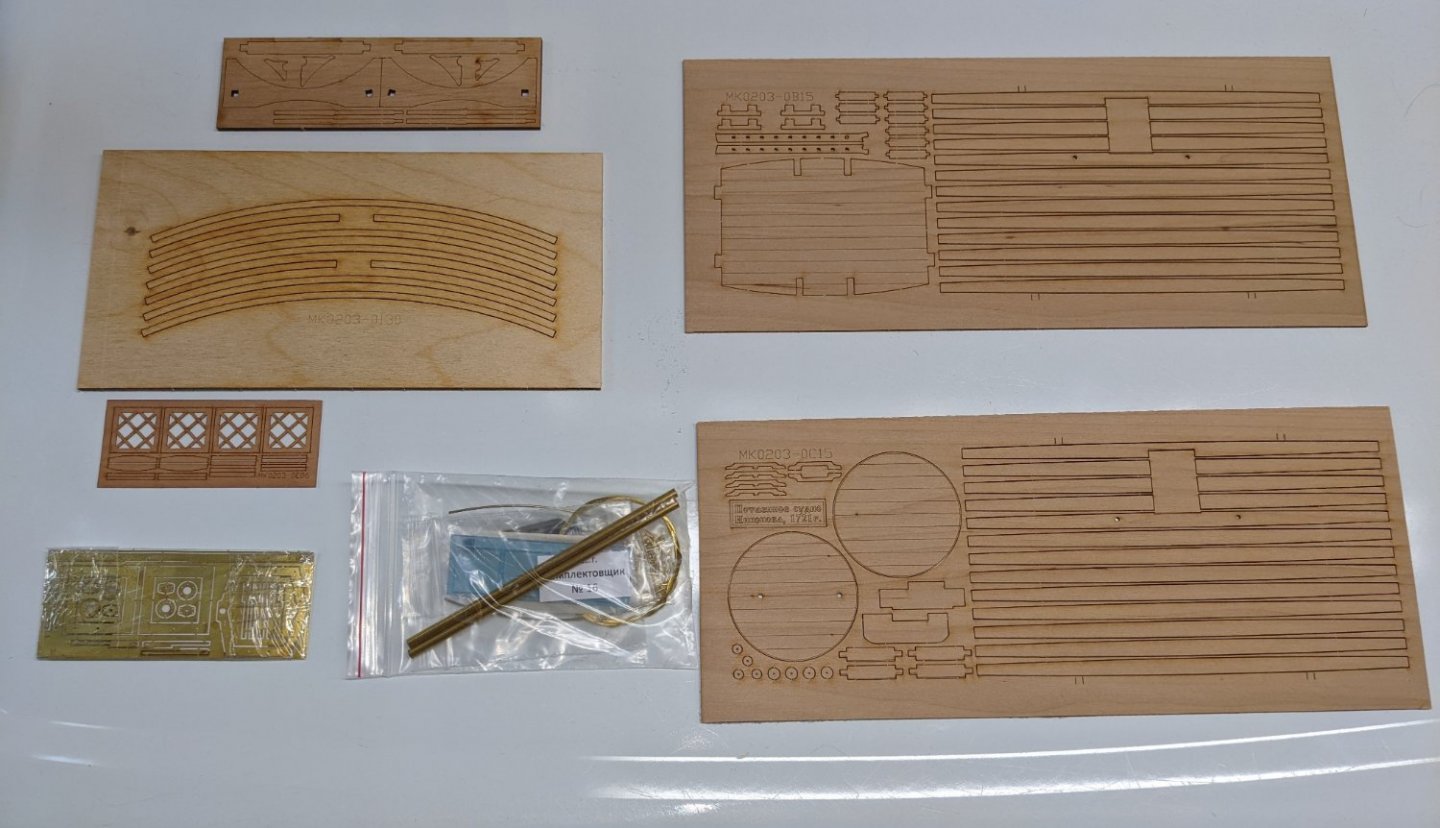
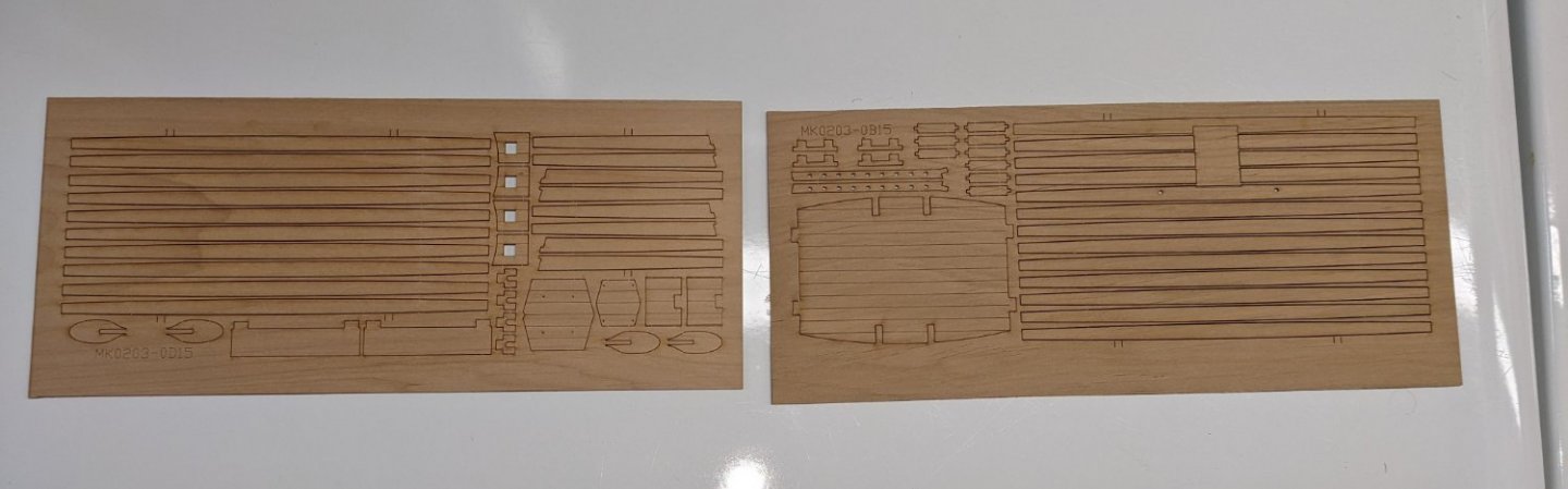
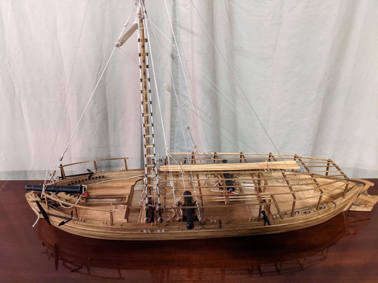
Just completed the Philadelphia Gun Boat. Took me just about 1 year at the speed I build, so I wanted to take on a simpler build, or what I call a "quick win". At least I hope it will be a "quick win". Then again it all depends on what you call "quick". This build will be one of those painfully slow logs. I work on models in my spare time, so please bare with me as this will be a slow log. I will start right out and say I am somewhat new to ship building and not an expert builder by any means. Maybe average at best but I enjoy the builds and have fun along the way. With that in mind I will start the process I have always been interested the the Secret Vessel "Morel". It seemed like such a quirky fun model - A wooden submarine ? I read a few other build logs and they builder seemed to have a lot of fun with the build so I thought I would give it a shot. Starting with the box contents,,,, Korabel must have some very precise laser cutters as some of the are really small. Seems like pretty good picture diagrams of the build In addition there is an 8 page pamphlet that contains instructions, part numbers, and depicts part locations on each wooden sheet. Seems very clear.


- 36 replies
-
- 5
-
-
- Morel
- master korabel
- (and 1 more)
-
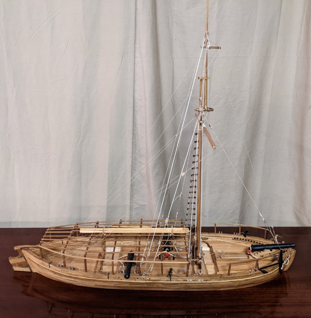
Awning structure is complete. As I mentioned previously, what should have been an easy task is made difficult by the existing rigging. More than once some choice words where spoken when I banged the rigging trying to get the awning battens positioned. At this point here is where I am going to "call it"... complete. Attaching the sails would normally complete the build, but I am not sure add much to the model. And beside, I like the bare wood look. Adding cloth sails folded up under the oars, to me (with my skill anyway) would not be a good look. Below are some final parting shots (pictures) .... It has been a lot of fun,,, especially for someone with a whole lot to learn about building model ships.
- 36 replies
-
- 5
-
-

-
- Model Shipways
- Philadelphia
- (and 1 more)
-
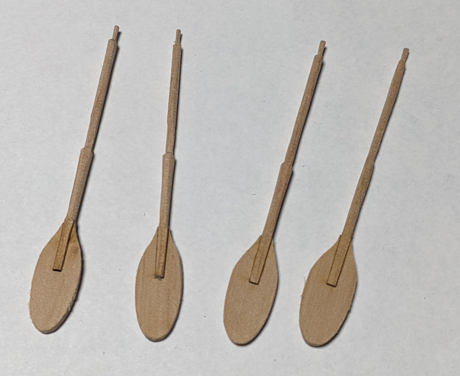
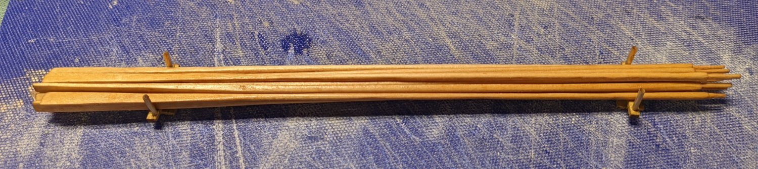
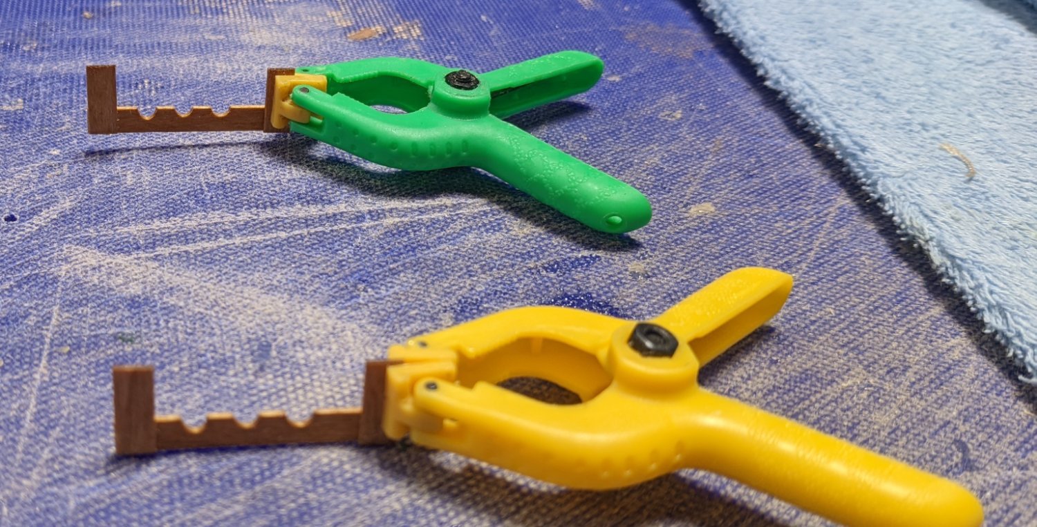
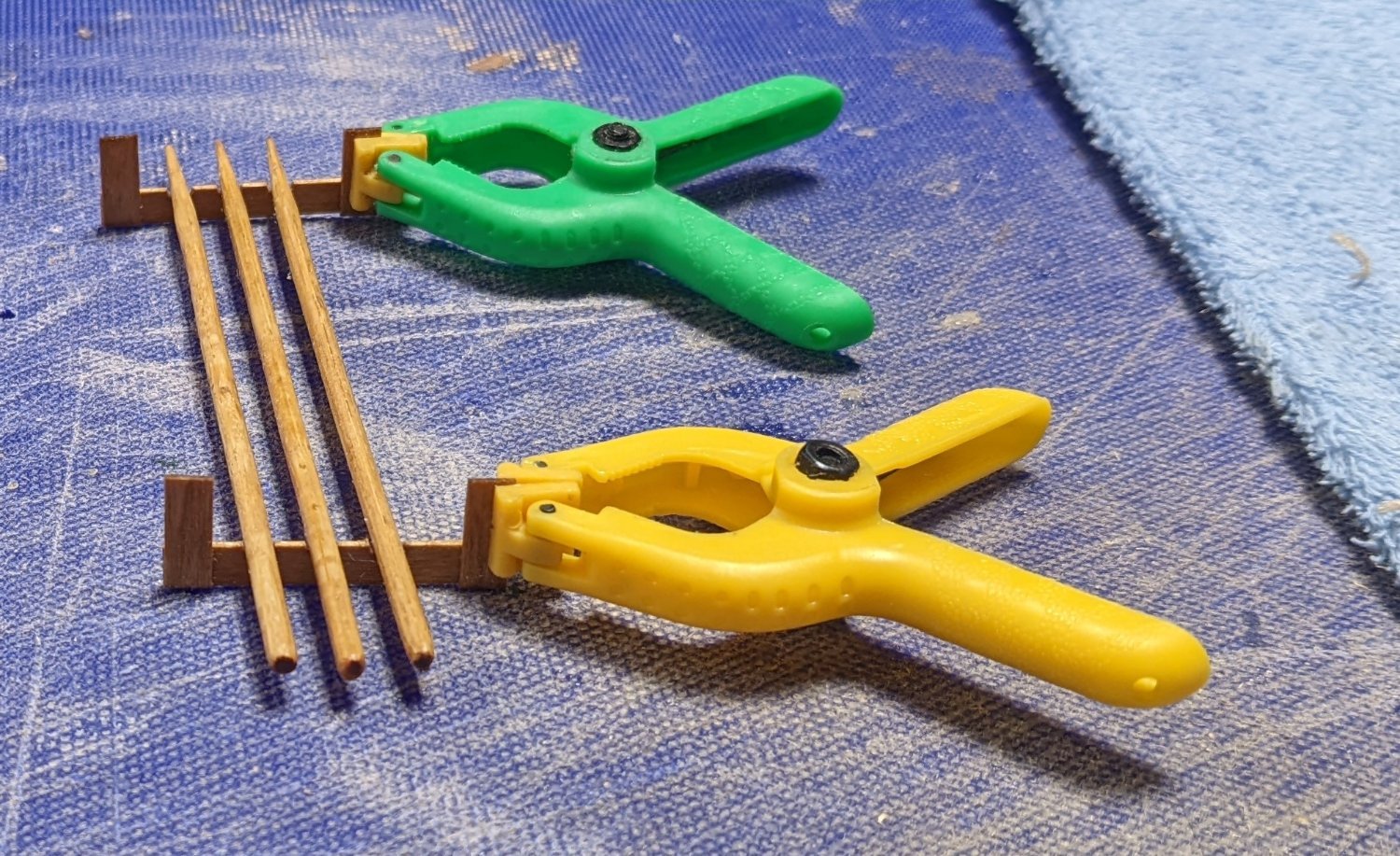
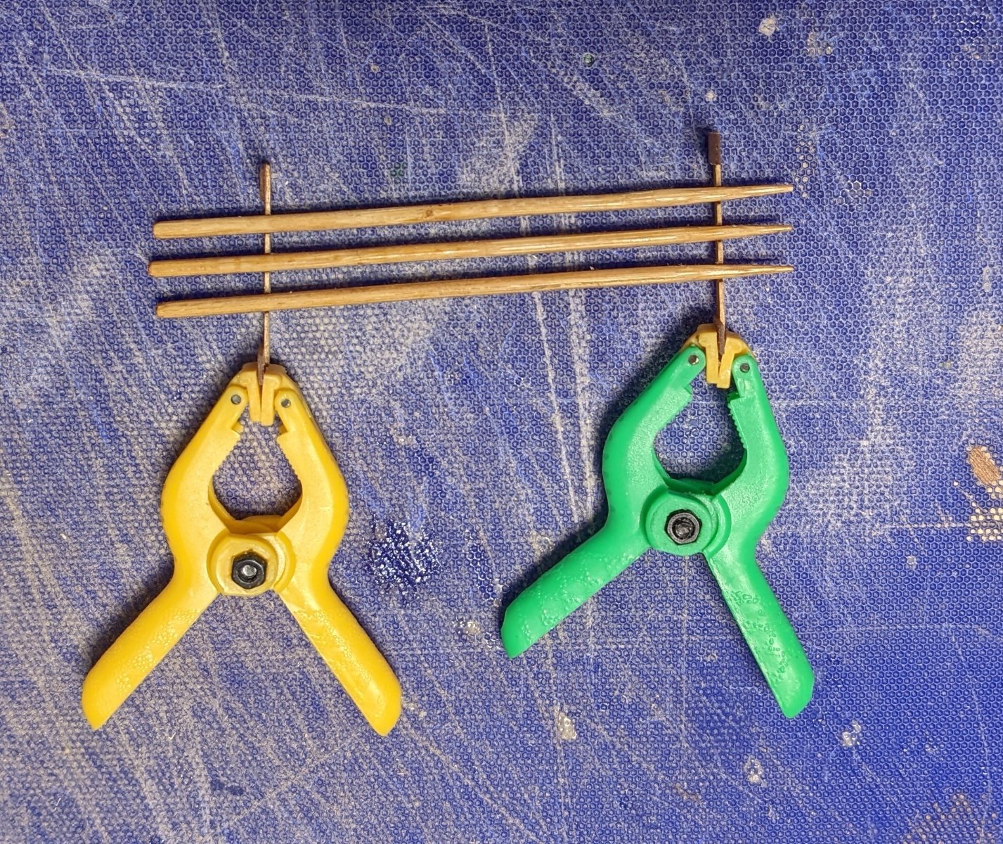
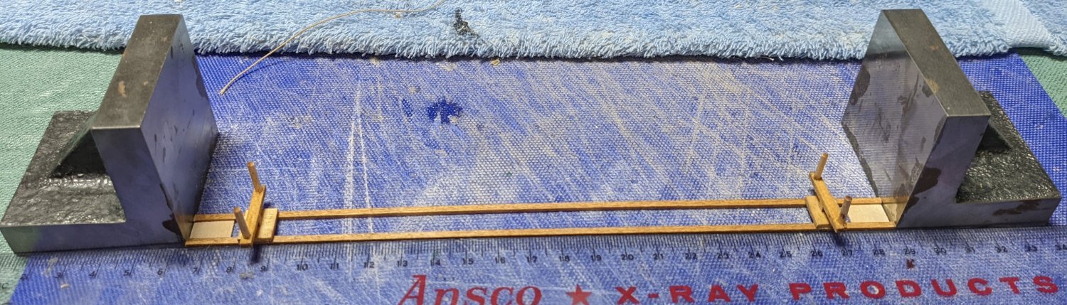
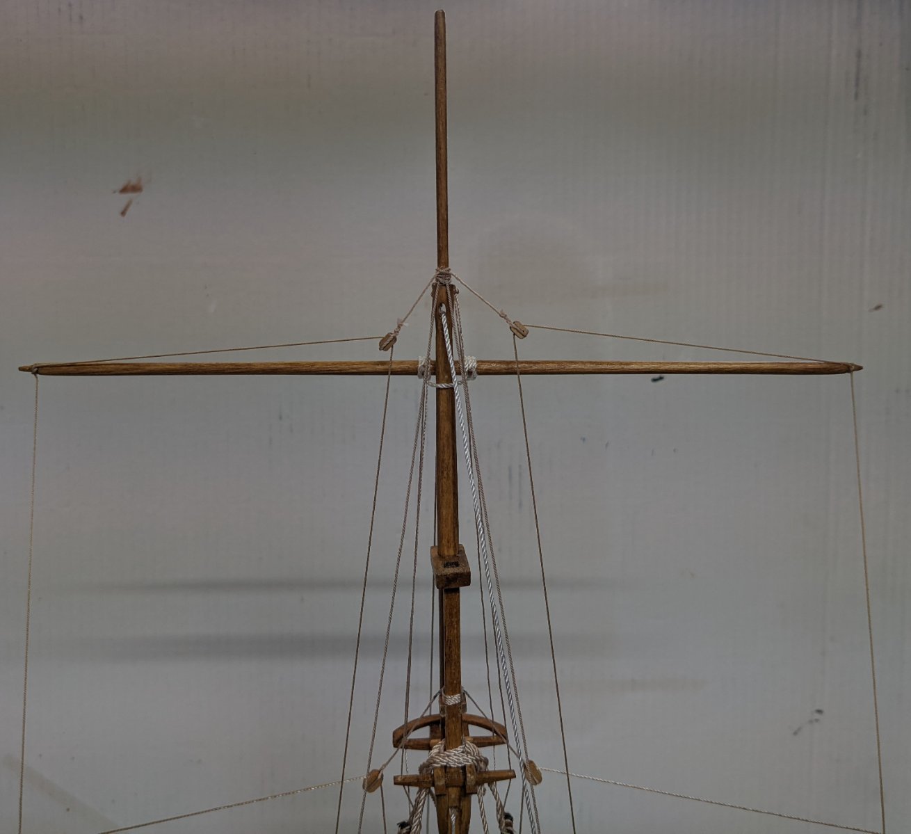
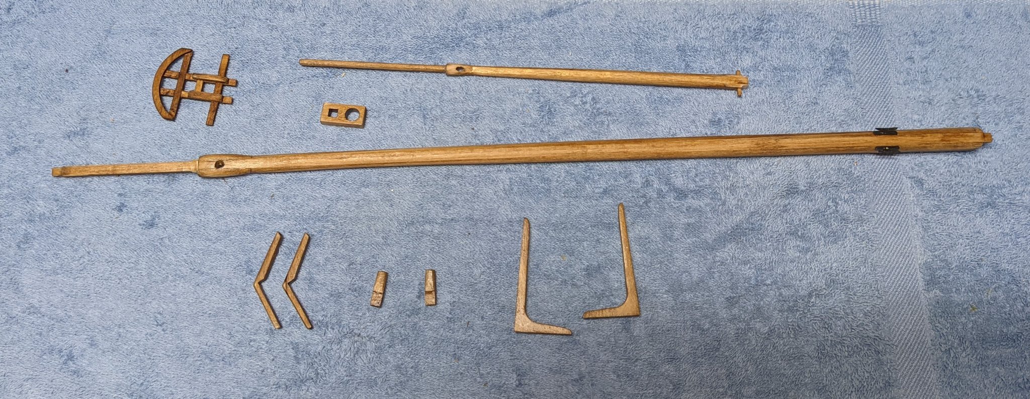
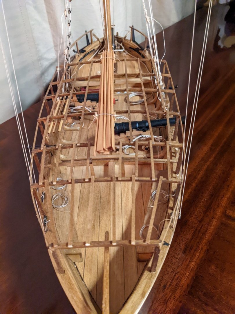
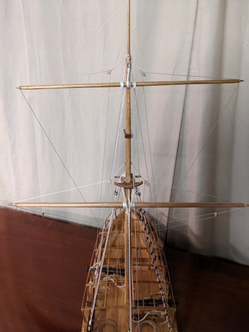
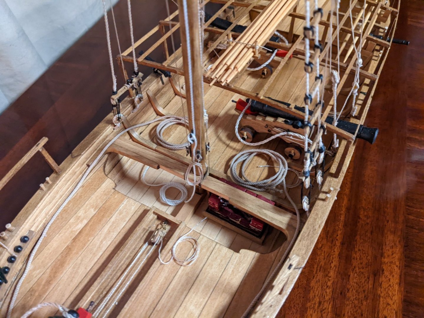
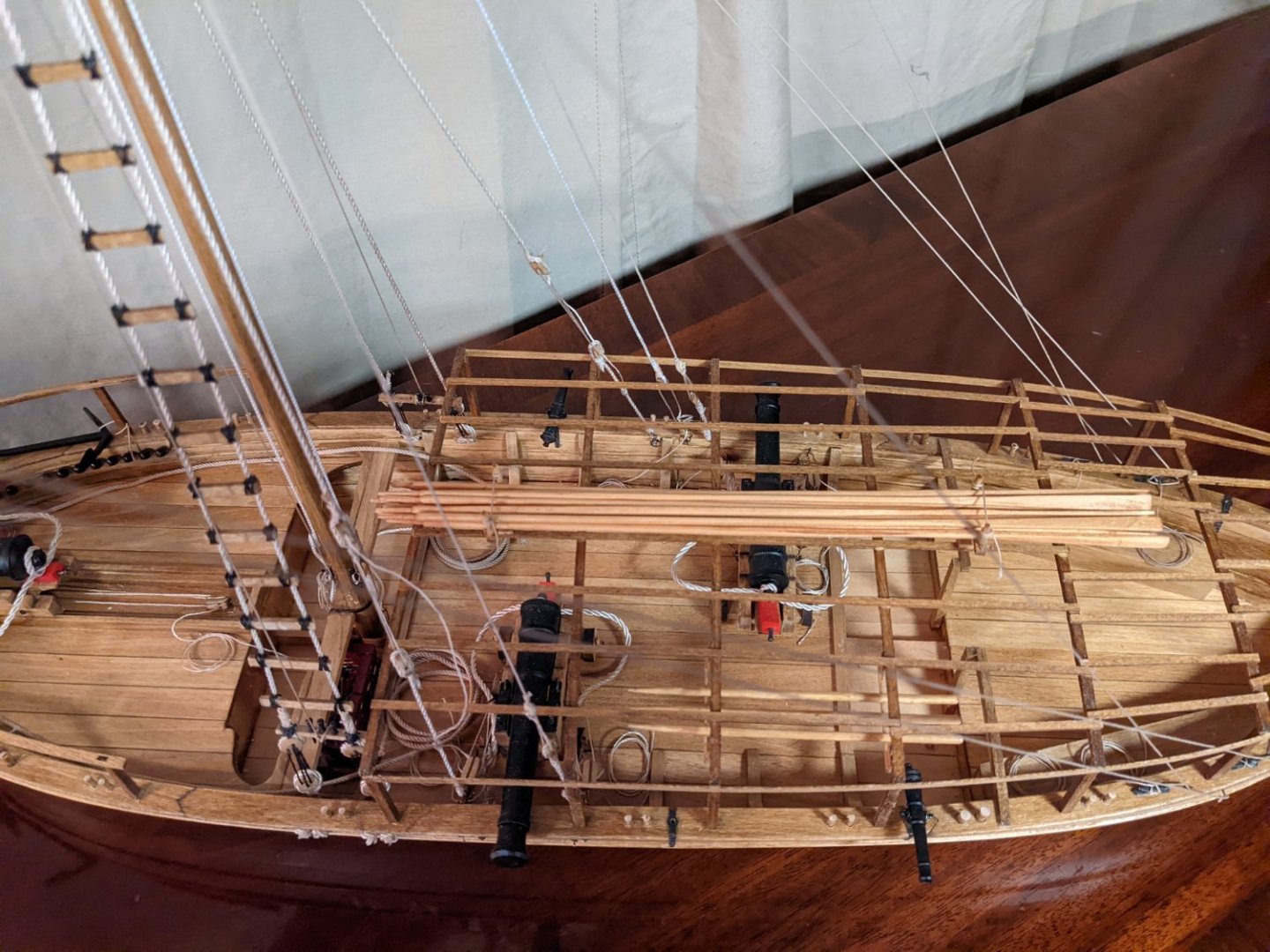
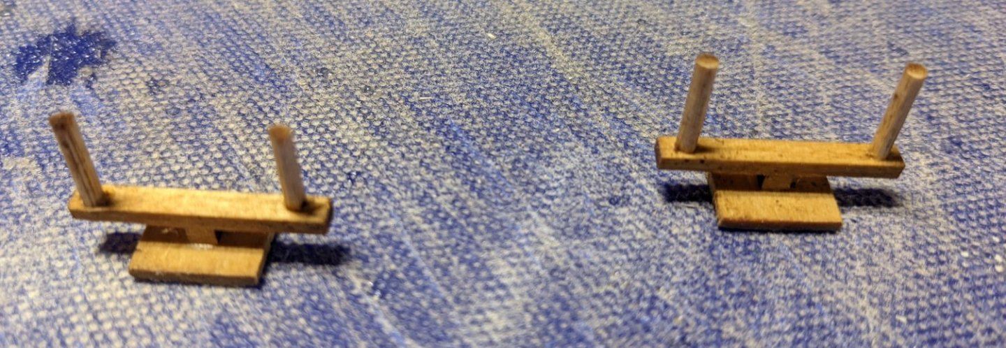
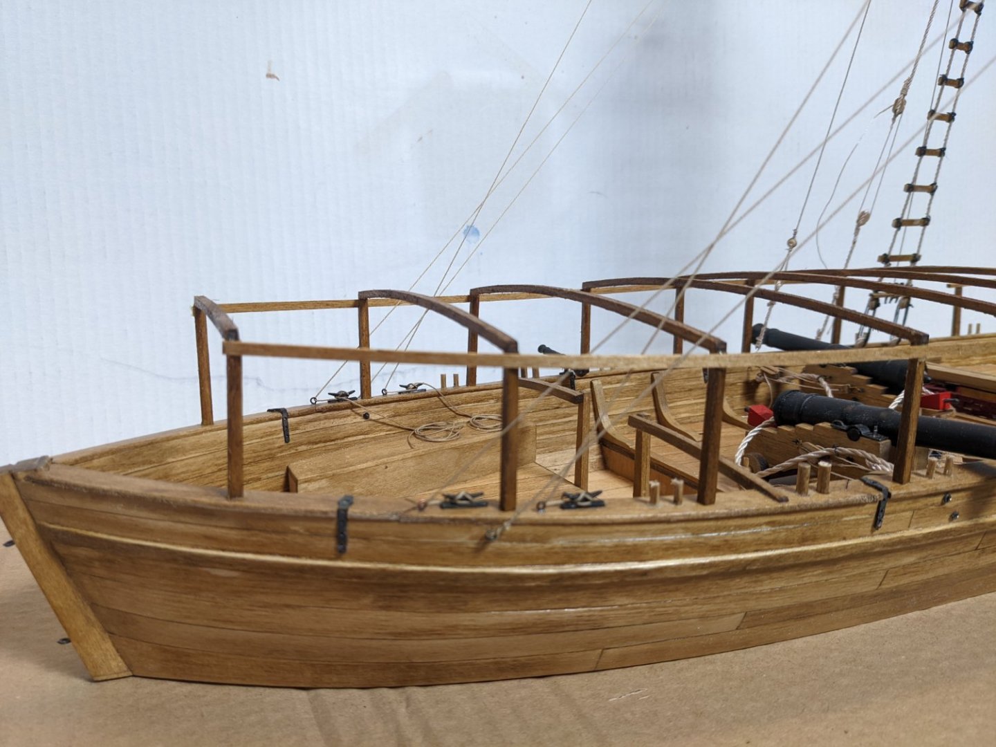
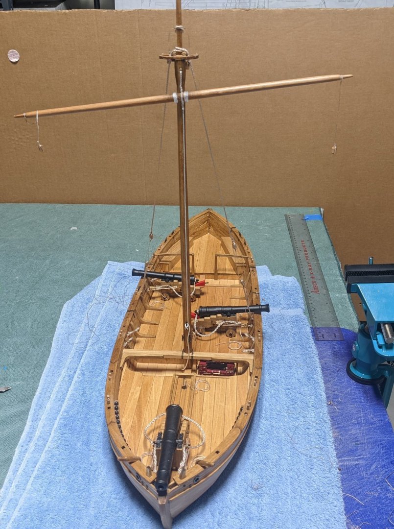
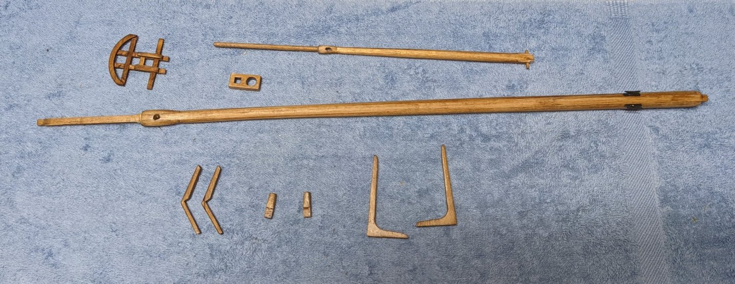
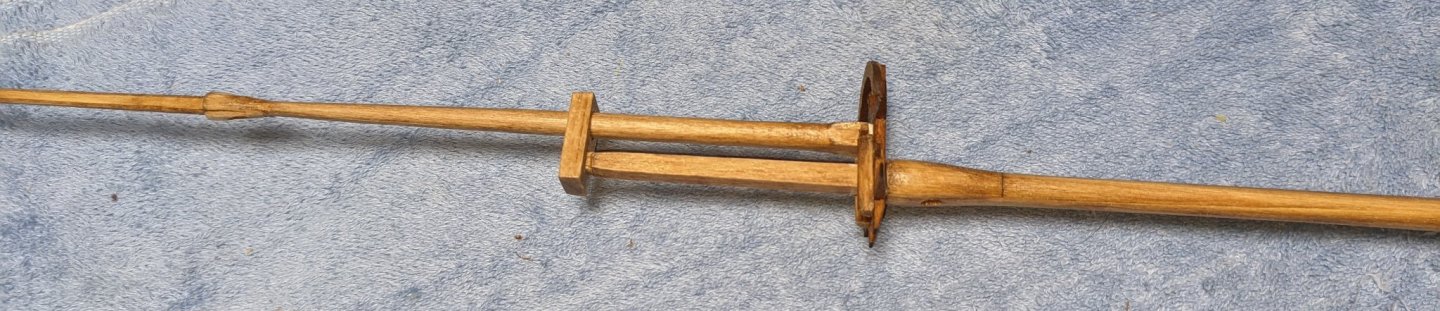
Decided to redo some of the rigging.. Just too many thick lines. I removed some of the thicker lines to where now only the Lower Shrouds, lower forestay, and lower backstays are rigged with the thicker line. All other higher rigging was replaced with the thin rigging line. Both halyards remained the thicker line as I figured the thicker line would be easier on sailors hands raising/lowering the sails. Starting working on the oar rack and oars. Pretty straight forward,,, that is if you follow the directions... Directions call for the first 1/2 of the oar to be square and then rounded off going into the blade. Foolish me, I just assumed I knew what an oar looked like - that being round all the way from the handle. Did not notice the first part was supposed to be square until I had finished them... But,, to me an oar should be round... You decide how you like your oars. And how they will eventually look on the boat Started working on the storage rack... Not much to it. Model does not include anything to put into the storage rack. Rather then just leave it empty hanging from the awning structure, I figured maybe put some simple poles... Just to have something. A more experienced modeler would probably build some kind of weapon to tool to go into the storage rack,,, but our crew just put poles in the rack. and how it will eventually look hanging from the awning structure. Next was the awning beams and stanchions. Instructions call to cut a notch in each beam and stanchion to better interlock them together. On the actual boat that was done to insure a strong joint, but in my model world that just was not going to look right. I practiced on some spare wood cutting notches and joining two perpendicular pieces of wood. I just could not make it look good. Main issue is trying to get the two notches to match up completely. If it is not exact, it just did not look right. Thus I took the easy way out and just glued the awning beams directly on top of each stanchion. I suppose not realistic, but a whole lot easier and looks much better that if I had attempted to notch each beam and stanchion. The additional 1/8 inch height on the awning did not really matter anyway. On to the battens... Instruction say the battens are installed last as it would be very difficult to do the rigging with the battens in place. That may be, but with the rigging in place, the battens are no easy task either. Especially the two enter battens down the middle of the boat. Since the oar rack (1/2" wide) is mounted on these two center battens, you have to get these battens exactly 1/2" apart. The also have to run very straight from fore to aft or they will really look off when sighting down the boat. This is not easy task with the rigging in place positioning them one at a time and gluing in place. I found the easiest way to insure a perfect fit is to assemble the two battens along with the oar rack off the boat. This will insure the oar rack will fit exactly between the two battens. The oar rack will hold the two battens together. That way, when the glue dries, just pick up the structure and glue it on the awning. Below shows the process. There are two temporary spacer pieces of wood at each end to insure the correct spacing Remaining shots show close up of some of the rigging.... Not that I am any kind of an expert on rigging... I HATE RIGGING.....just do not have the skill or patience for it.. and it shows in my build 🙂


- 36 replies
-
- 4
-
-
- Model Shipways
- Philadelphia
- (and 1 more)
-
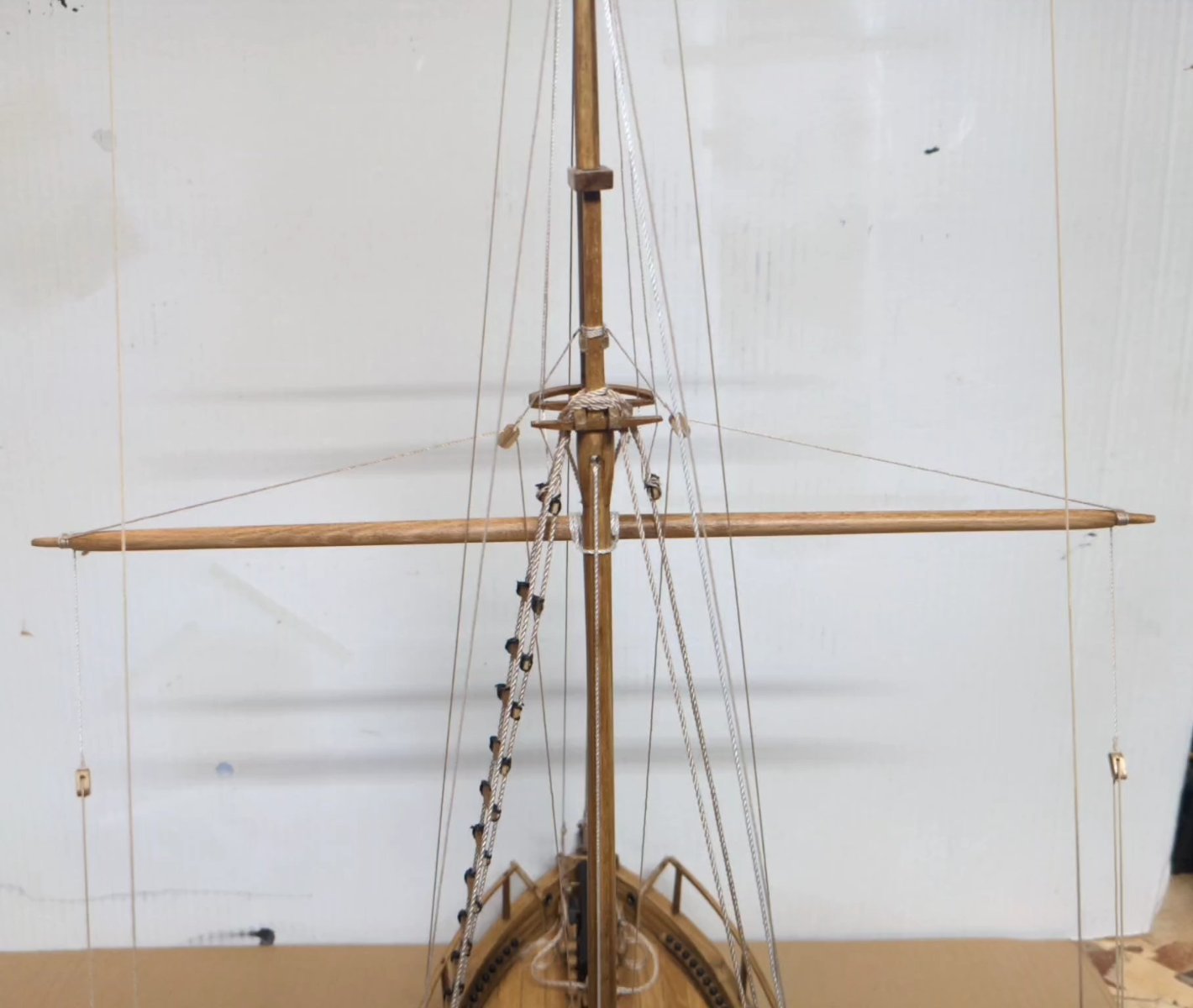
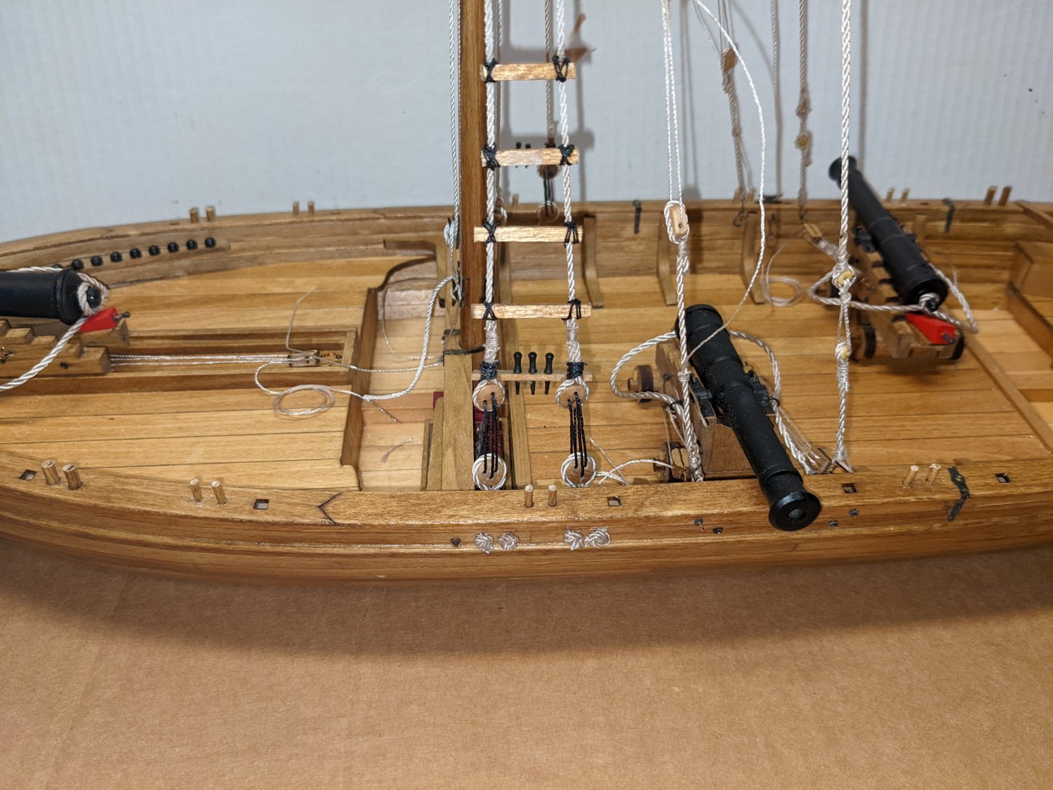
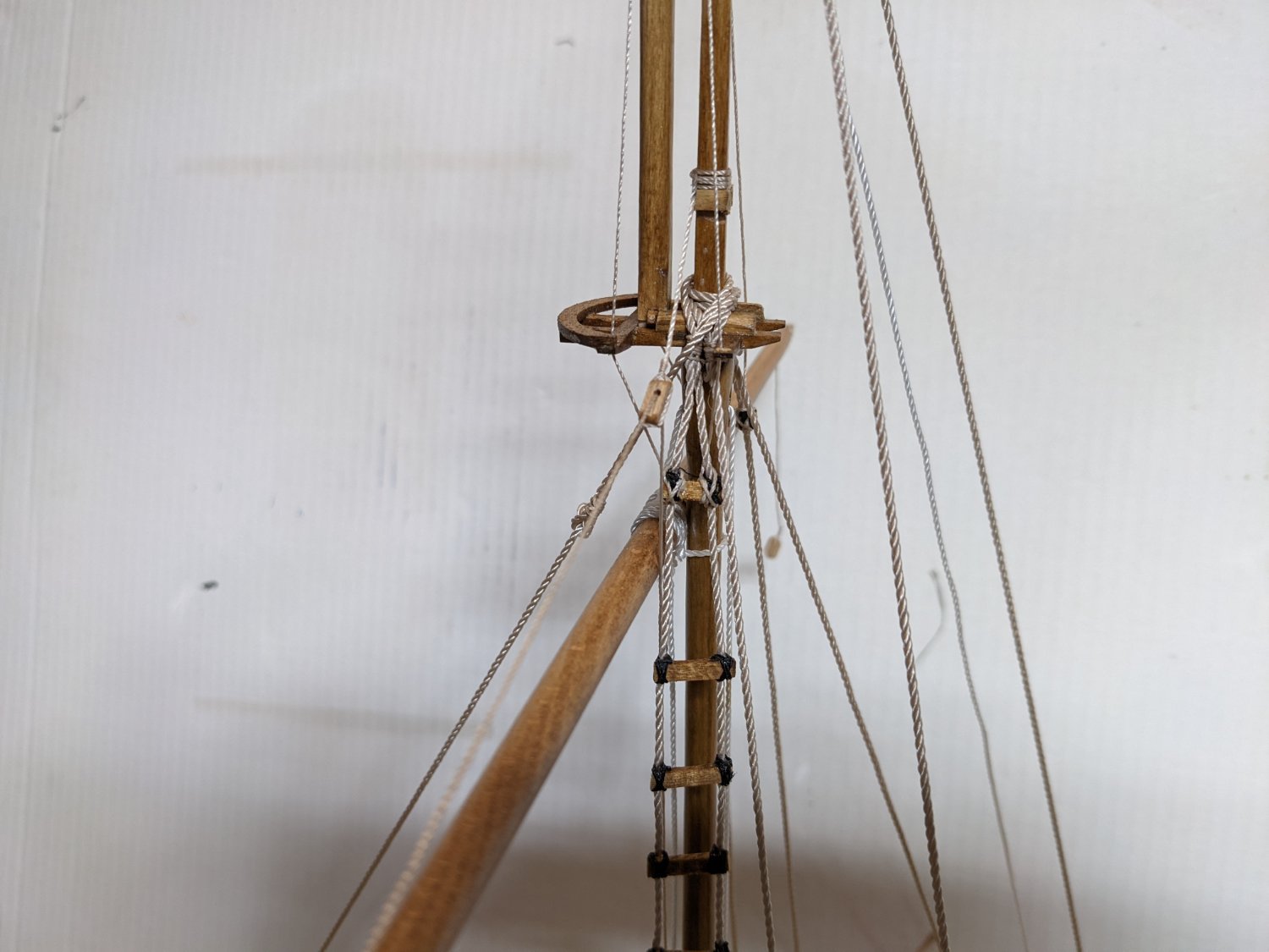
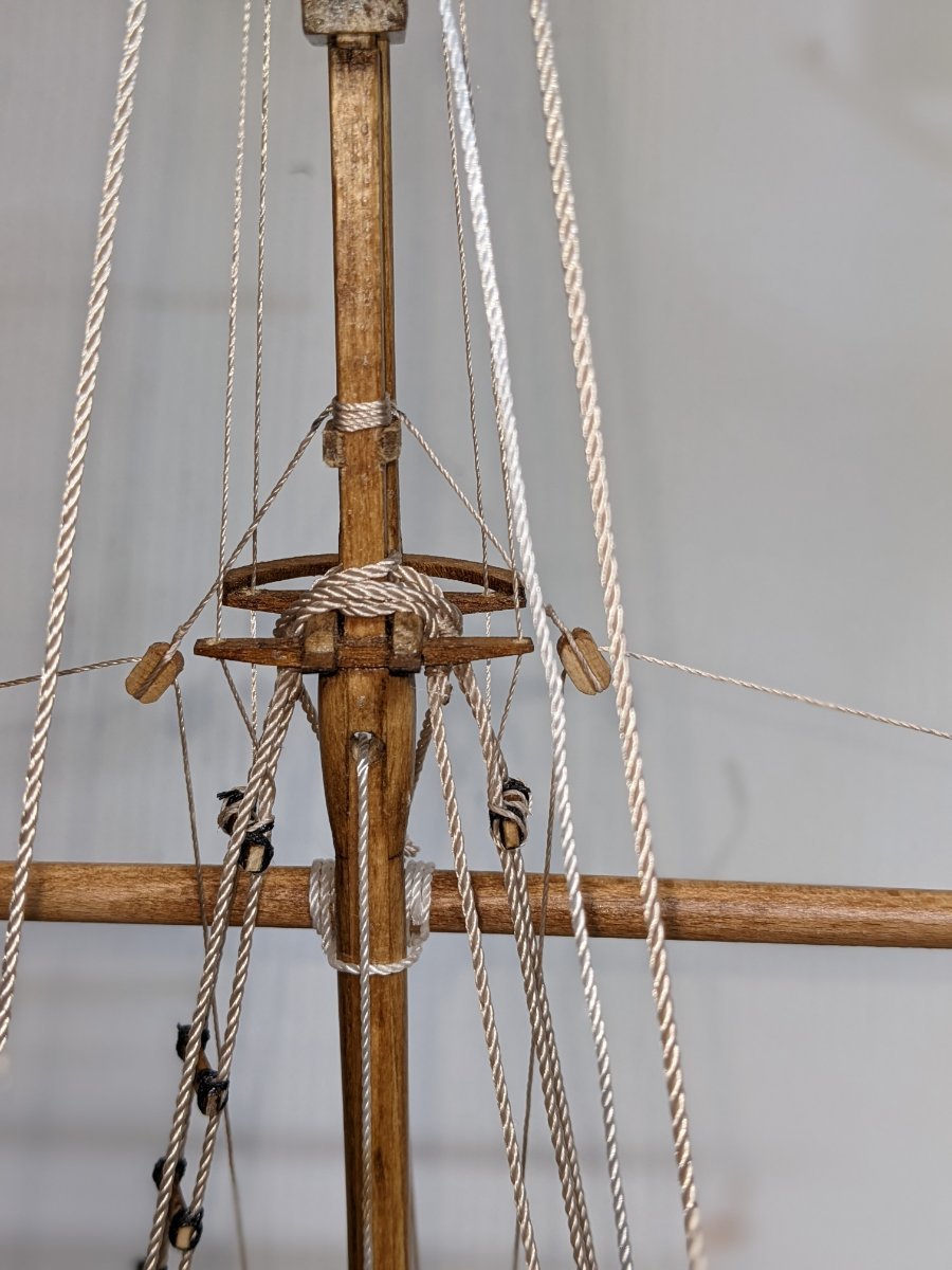
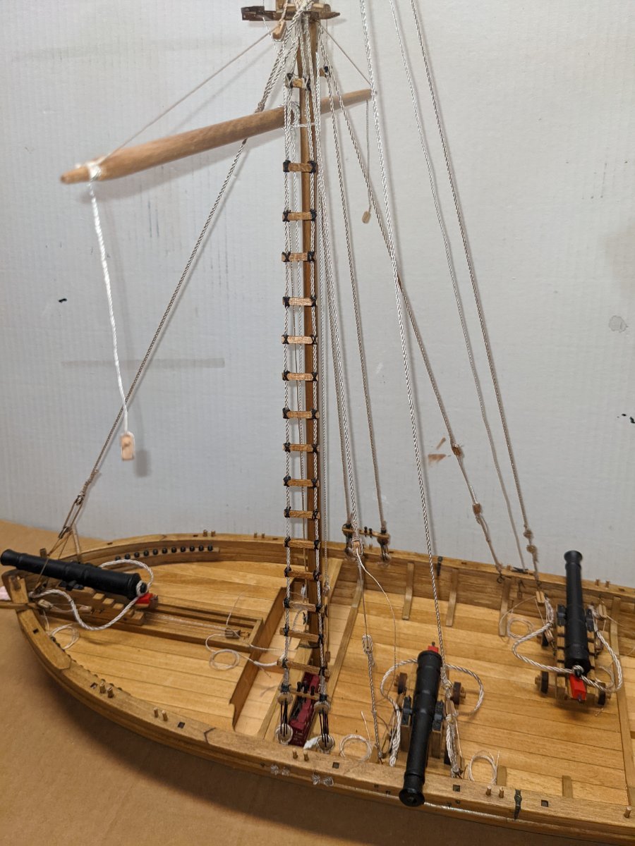
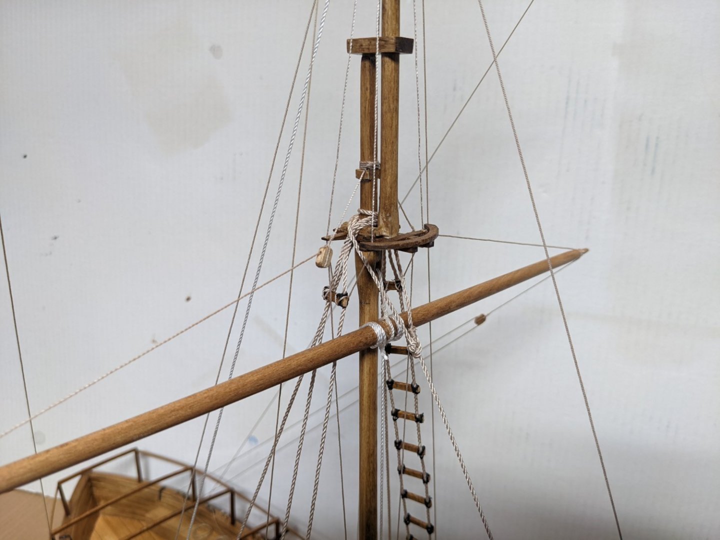
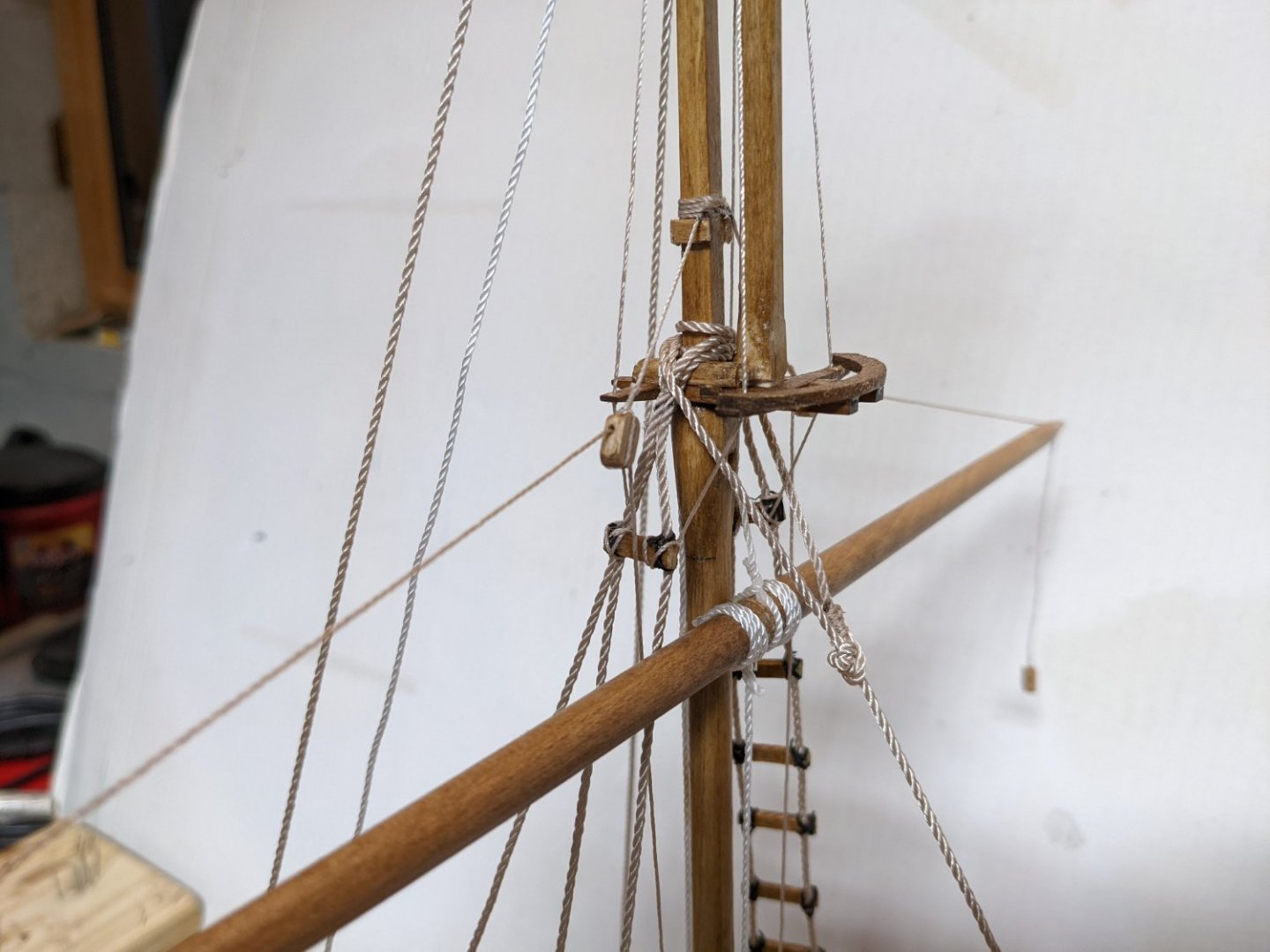
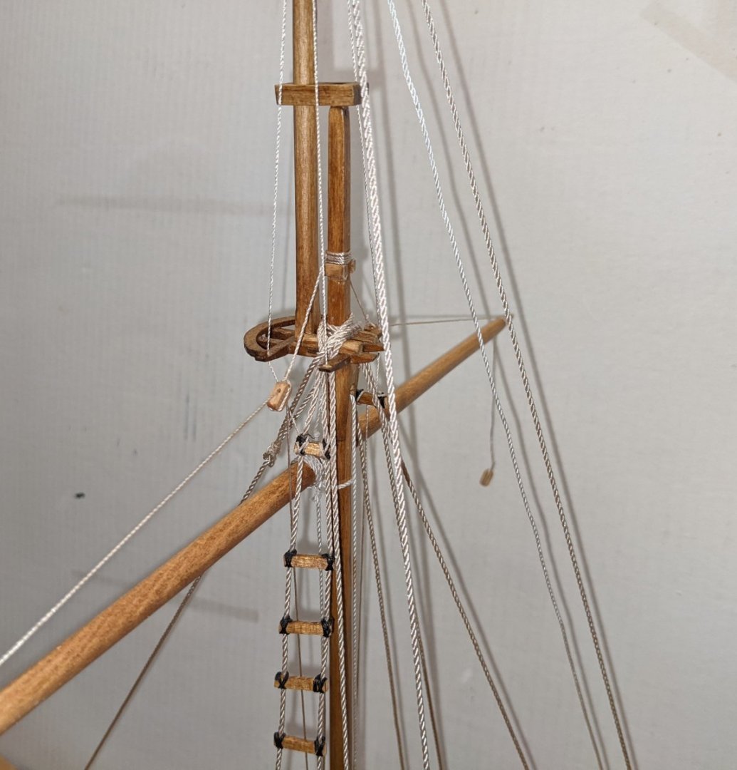
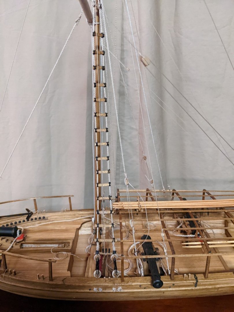
a few more shots showing the deadeyes beginning rigging and hull . Beginning the ladder rungs and belaying pins. This is my first model with ladder rungs (or rat lines for that matter). With my fat fingers and lack of skill, it was a trying task. I ended up first gluing the ladder rungs to the shroud and then added the lashing lines. Below is a look at the final ladder shroud. One point to note is the ladder rungs start out like the pattern diagram cut-out, but as they goes up the mast the rungs gets more narrow than what is shown as a pattern on the cut-out. If the shrouds hang straight from the Main Top no way can you avoid the ladder getting more narrow than the pattern on the cut-out. One idea that I think I like is to cut the ladder rungs the exact size as on the pattern diagram cut-out. Not only is that easier than trying to measure each rung, but this will insure the ladder rungs are the proper size. If this is done, the shrouds will widen some up to the futtock rung before they start getting wider as they go down toward the deck. Next model I have that has wooden rungs on the shrouds,,,, I may give this a try and see how that looks... Here is where the realists will roll their eyes... You might note I put rigged the ladder rungs on the port shrouds. The directions call to put them on the starboard shrouds. I did not realize this until I has 5 or 6 runs strung. Could not really see a reason to remove them as (other then not being true to the design) and rig them on the starboard shrouds. In the school of "do as I say and not as I do"..... you probably should rig them on the starboard shrouds. 🙂 A few shots of the lower forestay spreader around the canon. A few shots of the spaghetti of lines at the mast top. Not sure I agree with my decision, but for whatever reason I choose to use the white line for the main yard lift and top yard lift. I chose the thicker tan lines for the shrouds and forestay, and the thin tan line for the main and top braces. As you can see at the mast top, it is getting a little crowded with lines... Before you start your rigging, give some real thought as to what line is used where. And a couple shots showing progress to date... Note on the port side I only have two belaying pins... Not sure what happened, but after painting them, as I was taking them off the board, one fell off the paint platform. I even saw it hit me on the way to the floor.... But after that, it was not to be found... It is not that small, but it just vanished,,,, Anyway,,, I sent a note to Model Shipway telling of my fate, and they plan to send me one. Their replacement policy really is nice.


- 36 replies
-
- 2
-
-
- Model Shipways
- Philadelphia
- (and 1 more)
-
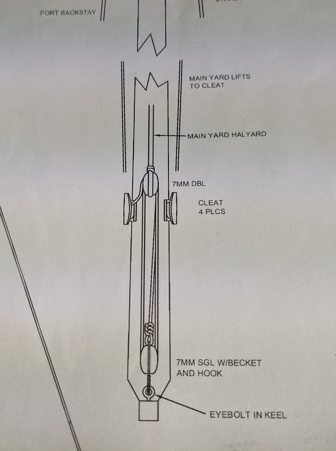
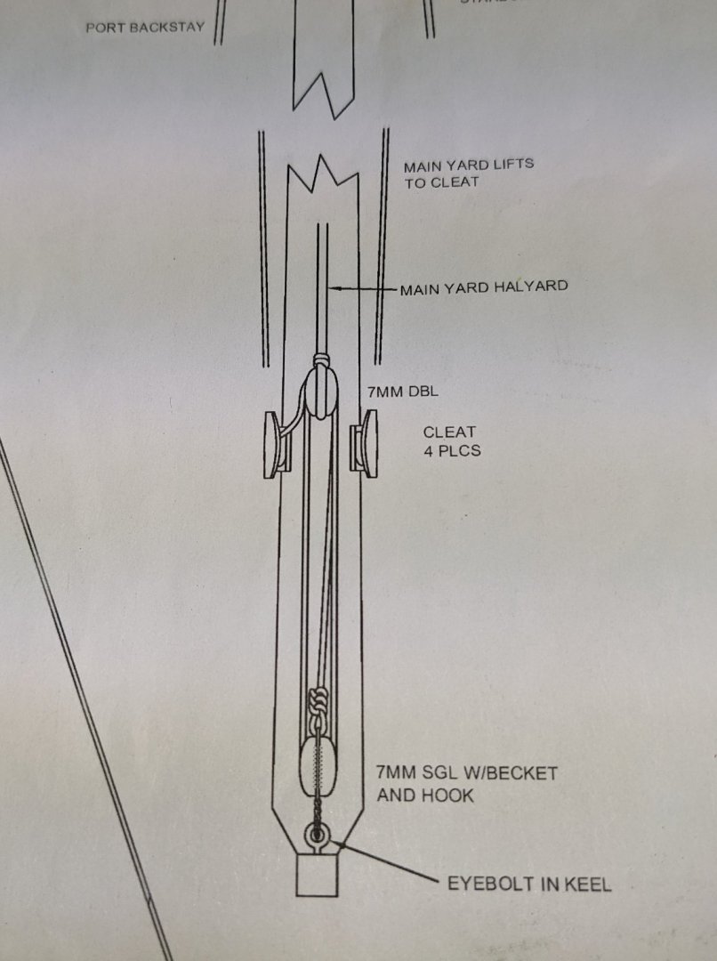
I wanted to point out a little confusion (on my part anyway) as to where to tie down the main halyard downhaul. The instructions say ,,,, "Attach the main yard halyard and the downhaul as shown". What is shown (or kind of implied) is the main yard downhaul going to a cleat on the mast. Problem is, the position of the four mast cleats. The two foreword mast cleats will be used to cleat the main yard lifts. One of the back mast cleat was used for the main halyard, leaving the last cleat on the back of the mast for supposedly the main halyard downhaul. Problem is this is not in a very good spot for the main halyard downhaul. Main halyard downhaul cleat really need to be on the front of the mast. Since it seems extra cleats have been provided (or at this point I think there are extra cleats), I added a cleat for the main halyard downhaul on the front of the mast. It shows in the picture below. I may regret this decision later on, but for now it seem like the logical position for it. Also rigging of the deadeyes have started,,,,

- 36 replies
-
- 3
-
-
- Model Shipways
- Philadelphia
- (and 1 more)
-
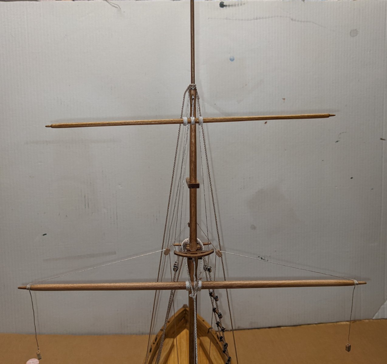
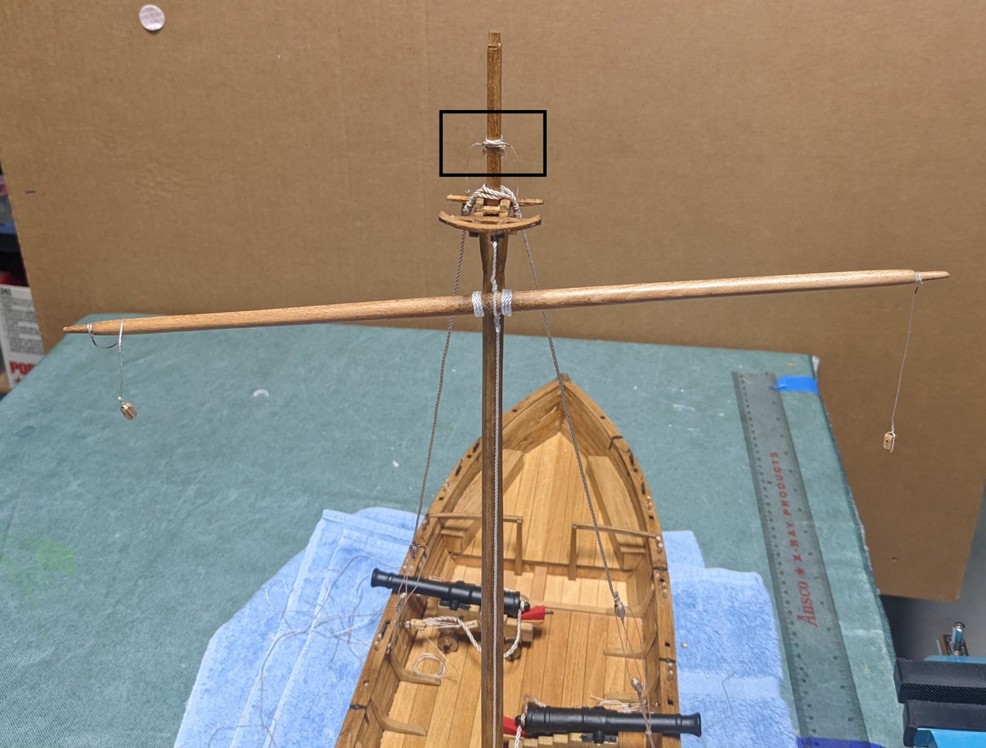
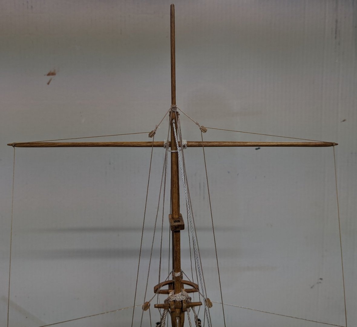
A little more progress.... Canons have been mounted, mast mounted, main backstays have been attached, and main spar has been pined to the main mast. Cook stove has also been placed in the location specified in the plans... Not really sure what Philadelphia ship designers had in mind when they located the cook stove. I can just see the discussion now between them.. "I know we need a cook stove, but where should be locate it on the ship? I know,,,, let put it directly under the wood structure that supports the mast" I guess the thought was that the ship would be sunk at war before the cook stove burned through the mast support 🙂 One note,,,, Instructions about this time in the build state talk about "make up and attach but do not glue the main yard brace pendants as shown in Detail 5-3.". Main yard pendant is shown above with a black box. Not really sure what ""make up and attach but do not glue" really ment. I assumed that ment make up the main yard pendant (and glue it), but do not make up the lines. I guess "do not glue" really means "do not glue" as problem I had later was slipping the backstay lines over the main yard pendant blocks. Not a big deal as the blocks are very small, but the loops for the backstay (and shrouds later on) ended up being a little bigger than they needed to be so it would fit over the main yard pendant blocks. Going with the theory "do as I say and not as I do", make up the main yard pendant lines and block, but hold off attaching them to the mast until after the backstays and shrouds have been attached.


- 36 replies
-
- 1
-
-
- Model Shipways
- Philadelphia
- (and 1 more)
-
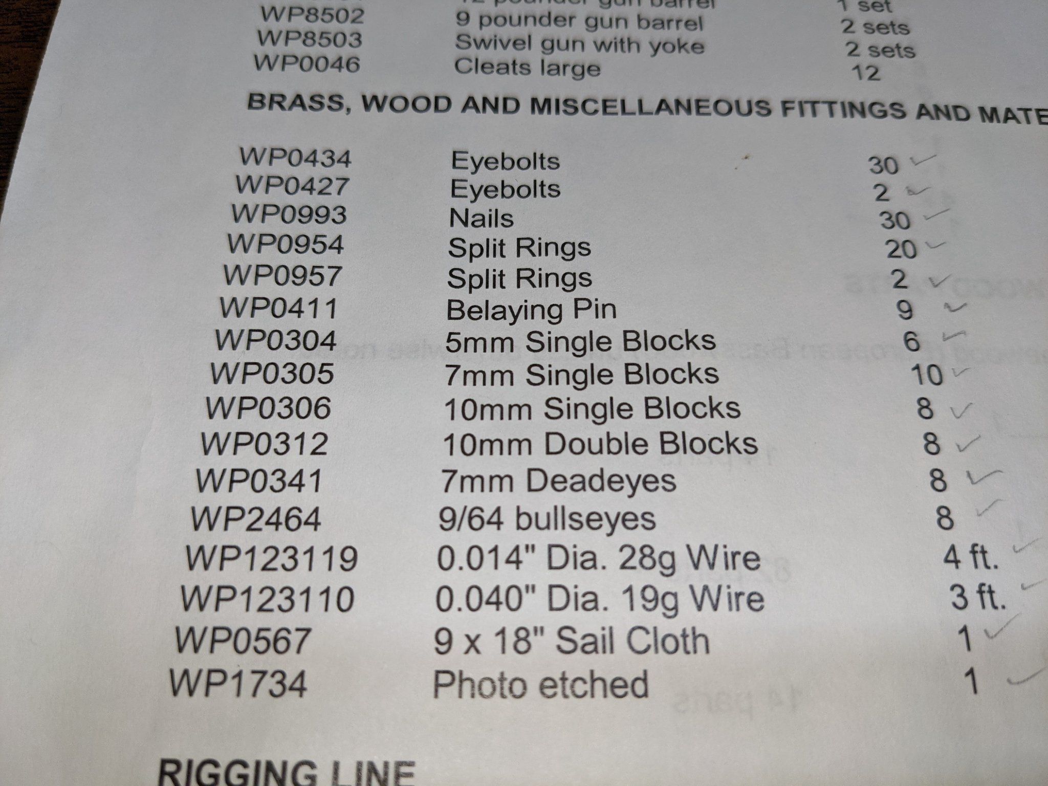
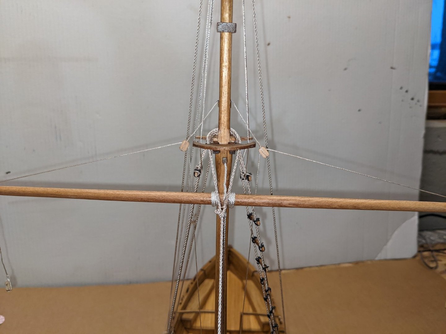
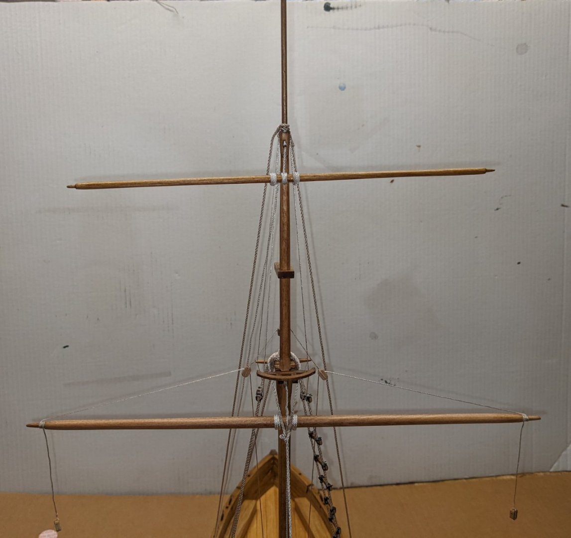
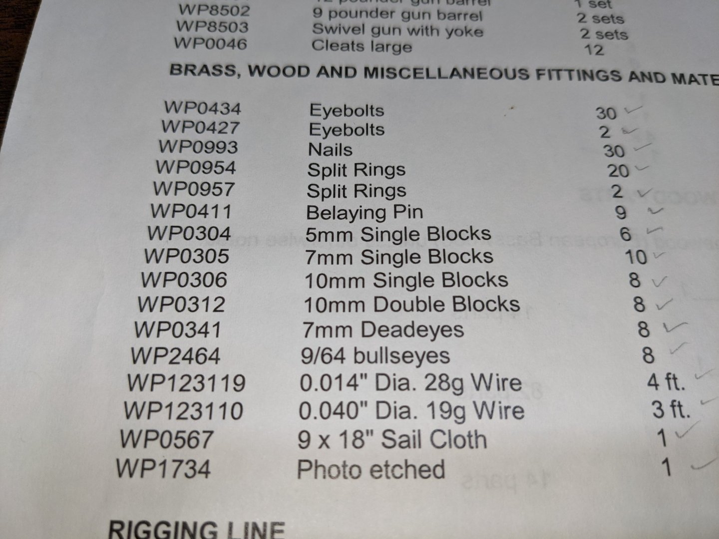
Next step was to add the mast top, main halyard, and step the mast. One thing I noticed on diagram sheet #5 was the description of the main yard halyard. It shows it terminating into a 7mm double and 7mm single blocks. Problem is the Philadelphia kit did not include an 7mm double blocks. For those of you who purchased blocks from Syren or other sites this is not big deal. But if you plan to use the blocks included with the kit, you will be missing a 7mm double block needed to complete the main yard halyard. Once again Model Shipway to the rescue. I sent them a note describing the issue and they gladly sent me a 7mm double block to resolve the issue.
- 36 replies
-
- 1
-
-
- Model Shipways
- Philadelphia
- (and 1 more)
-
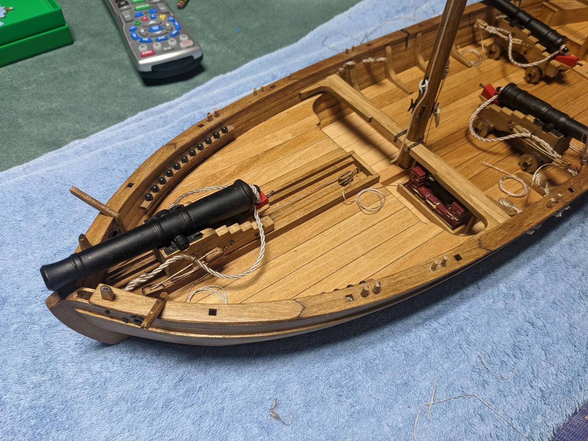
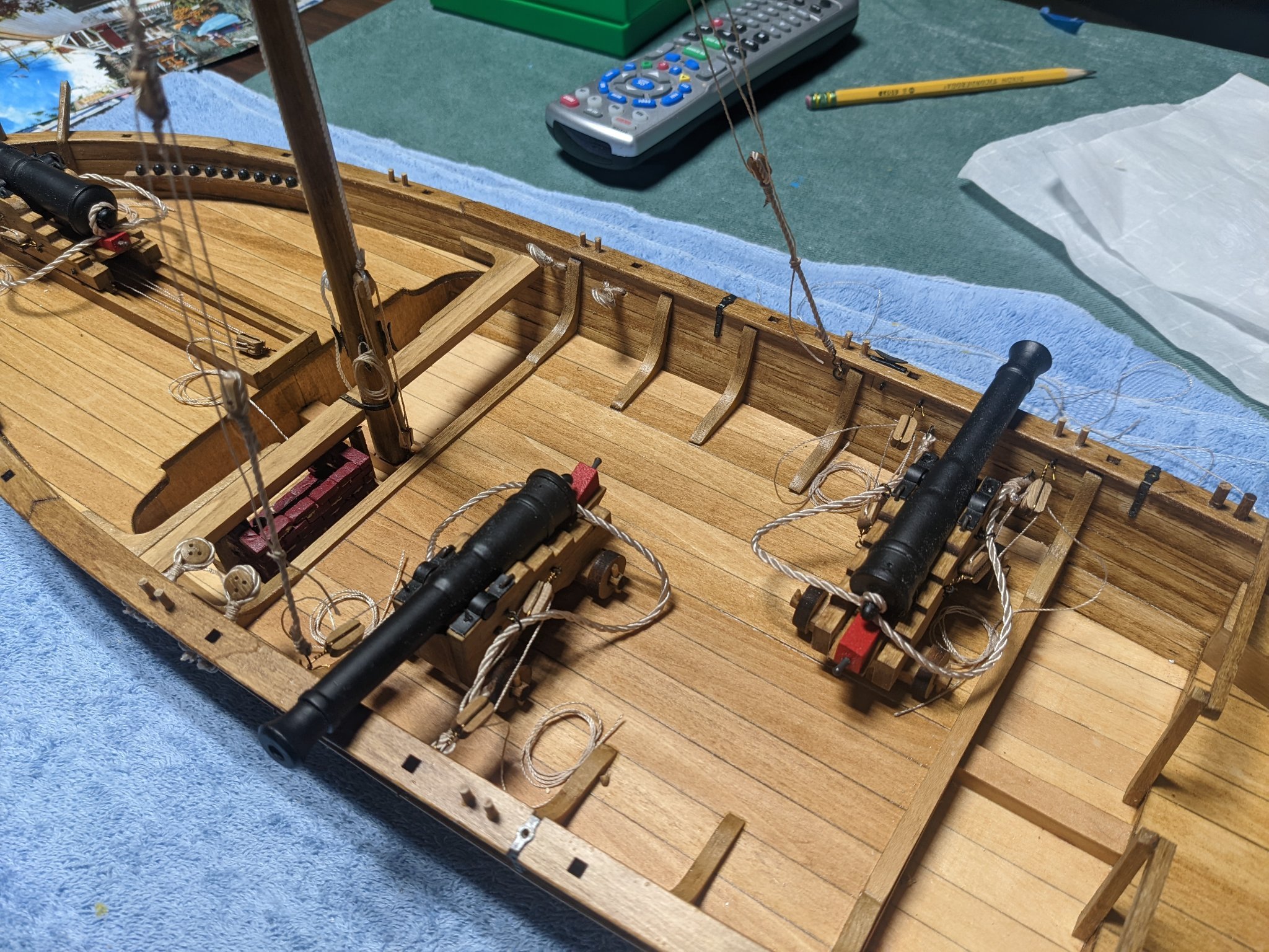
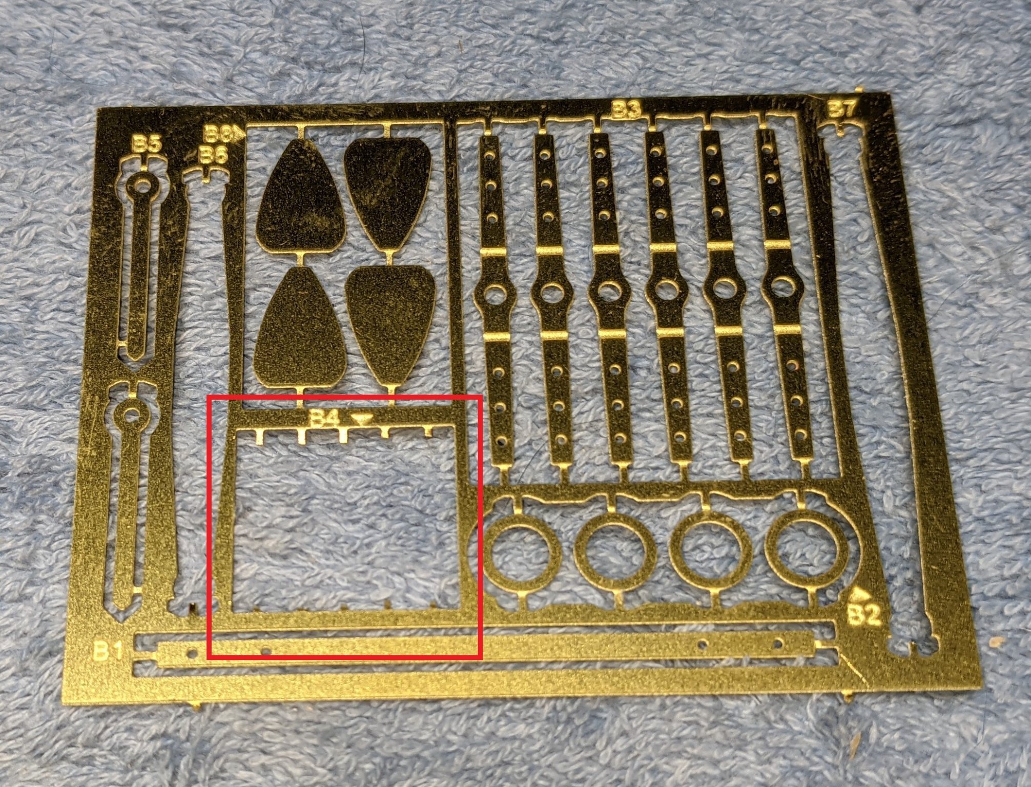
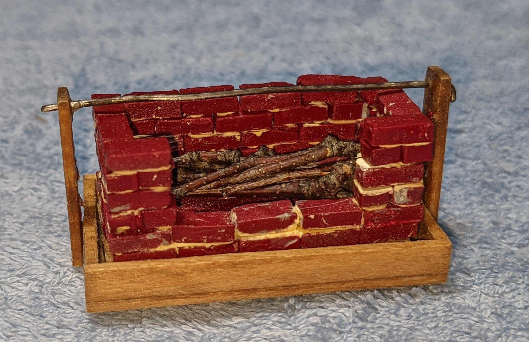
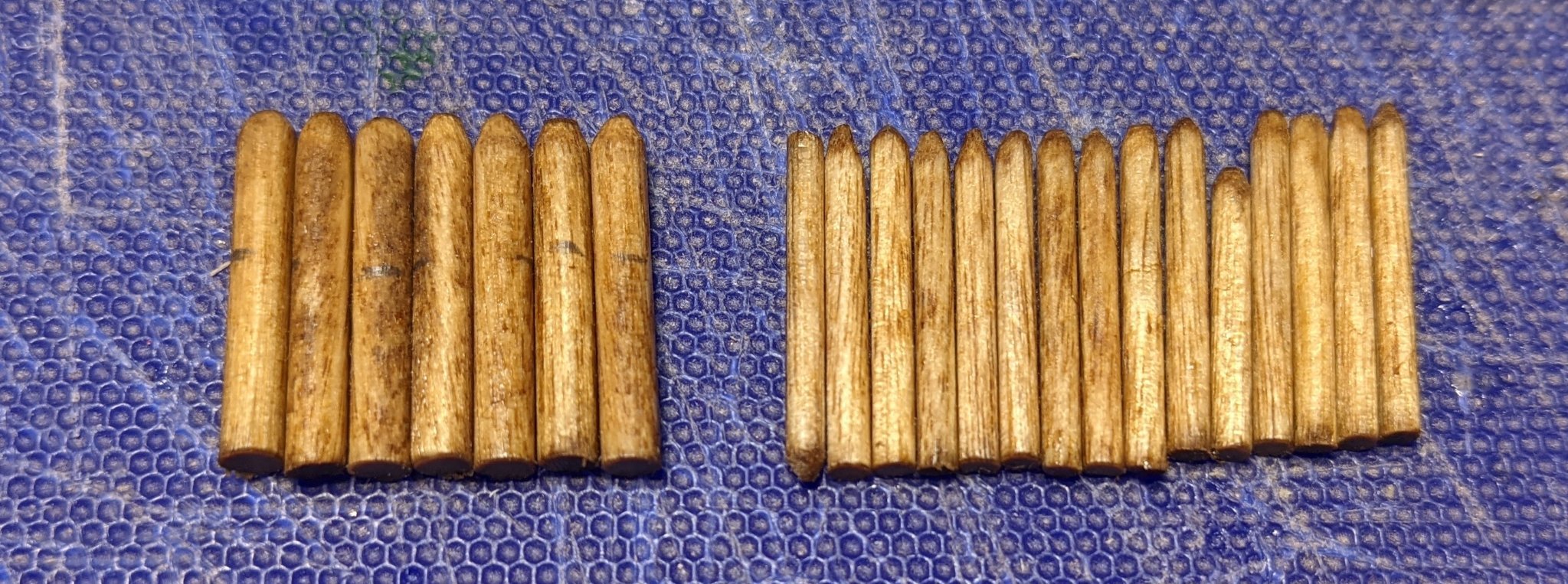
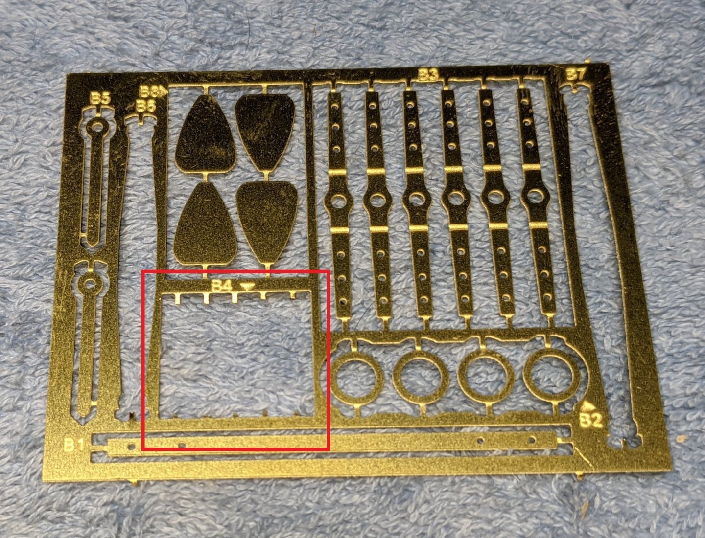
Probably should have mentioned this before, but I just thought about it... One set of items on the brass sheet are parts B4. They are little washers that are used throughout the hull and the canons. There are 20 of them supplied. Depending on your point of view, 20 is not enough of them. Even the instructions seem to indicate that fact. Early in the build the instructions say.. There are quite a few eyebolts for guns and rigging on the Philadelphia. These eyebolts were installed by drilling through the ceiling planking and the outer planking, inserting the eyebolt, and then applying a washer and peening over the end of the bolt to secure it. Later on in the build, after you have used the 20 washers, the instructions indicate to "simulate" them. To simulate the washers and peened ends on these bolts on the hull exterior, snip them off a bit proud of the hull and draw a circle around them with a fine point black Sharpie pen. Keep the pen in close contact with the bolt end. ModelExpo to the rescue and their great policy of replacing any missing or broken part. In my case, the part was not missing or broken. I explained that since I started using the washers I really did not what to finish up "simulating" them with a Sharpie and asked if they could send me some more washers. They very quickly agreed and promptly sent me another brash sheet. A great company... Below just shows that brass sheet and the spot where 20 washers were located. Back to the build.... Instructions do not mention the cook stove, but several picture are show on the model sheets. So pick an appropriate time to build it before the deck gets too cluttered and before you install knee K1. Below is my attempt at the cook stove. As others have done I used Sculpey Super for the bricks. Used the mold from the wood bricks on the laser cut sheets, cooked them in the stove, and painted them. The bricks turned out great. The quality of my cook stove really looked like some army guys (non-brick layers) built the stove. 🙂 Staining of mast and top mast, knee (K1), catheads and mooring bits Instructions indicate after the Mast (lower mast) is build it should be fitted to the hull with the mast partner. It also talks about not gluing in the Mast to the hull in the event you need to repair the Mast in the future. Good words, but the future is now. Do not glue in the Mast, or even fit it to the Mast Partner at this time, as in the next step it talks about removing the installed Mast to add the Top Mast. After the Top Mast is built "Main Top" is built. At this time, be sure to dry fit the Mast, Top Mast, and Main Top, as not doubt some "adjustments" will be needed to get a good fit. Below shows Mast, Top Mast, and Main Top dry fit after "adjustments" Below are the cut and stained Thole Pins and Bitts from the dowel rods. The are inserted through the Rail Caps at indicated locations. I rounded off the top of them a little so they did not look completely like dowel rods sticking up out of the hull. The are easily inserted into the Rail Caps and stick up about 1/4 inch. Below is progress to date,,,


- 36 replies
-
- 3
-
-
- Model Shipways
- Philadelphia
- (and 1 more)
-
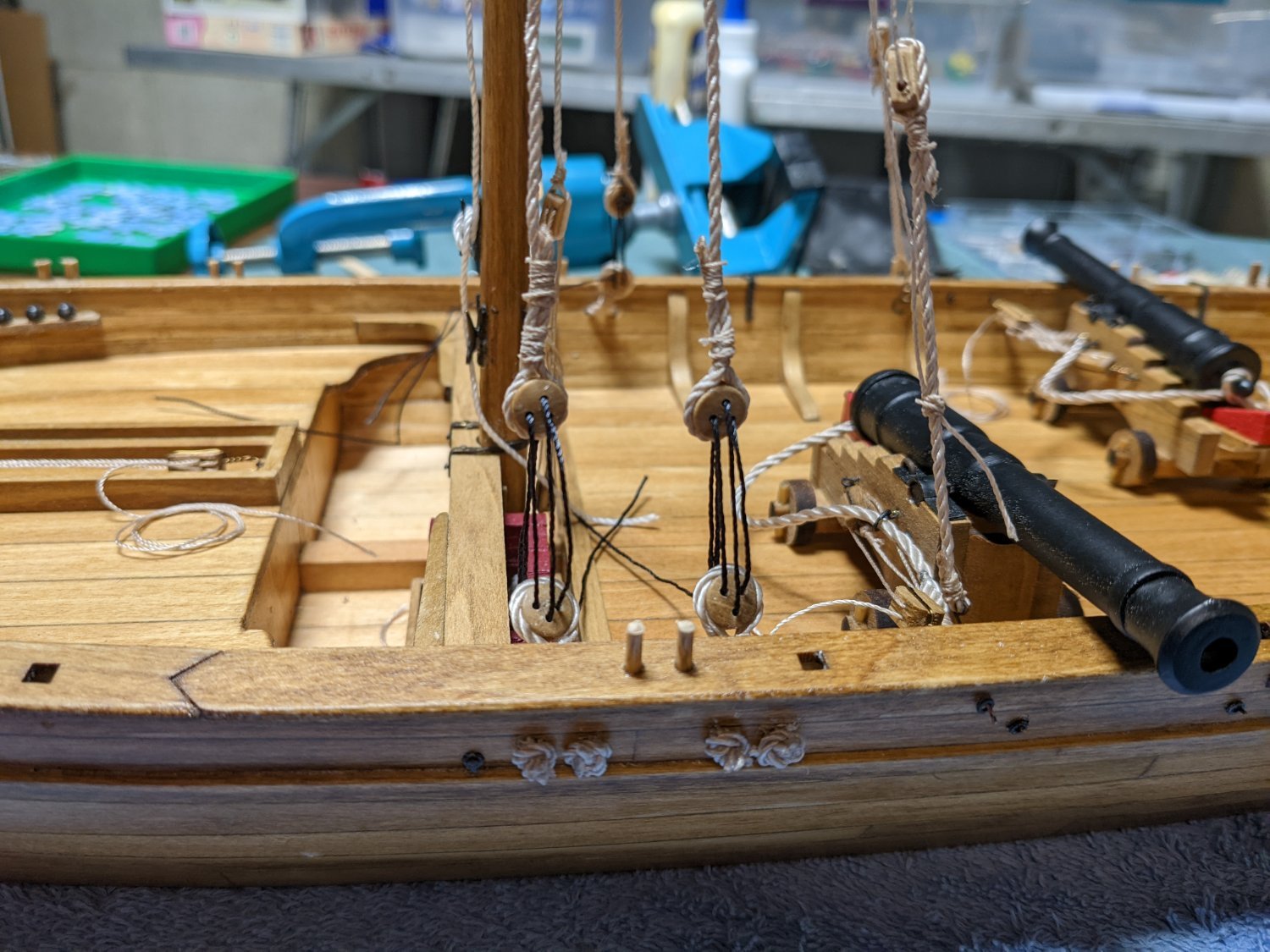
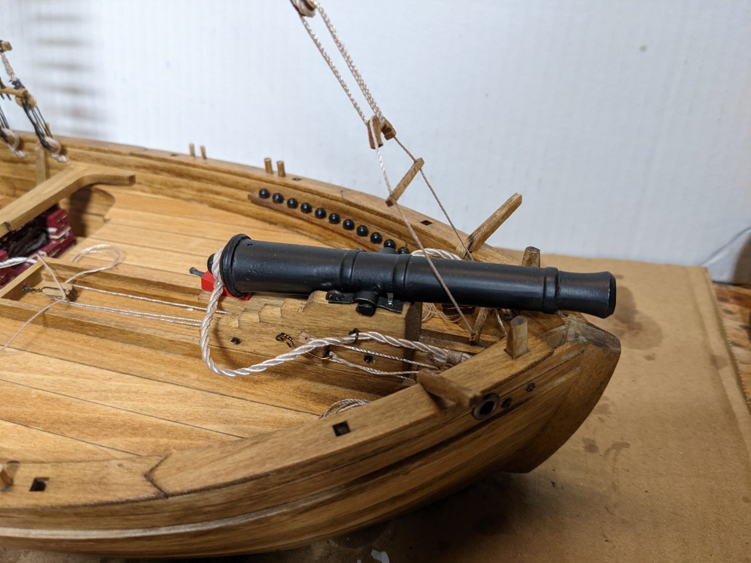
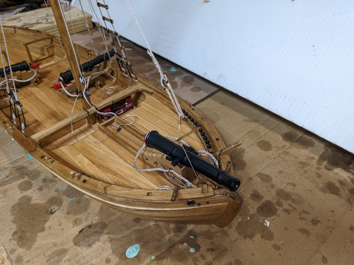
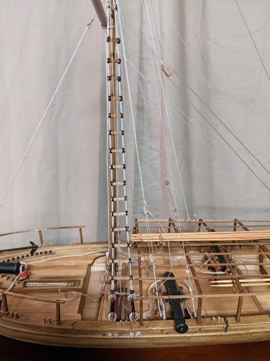
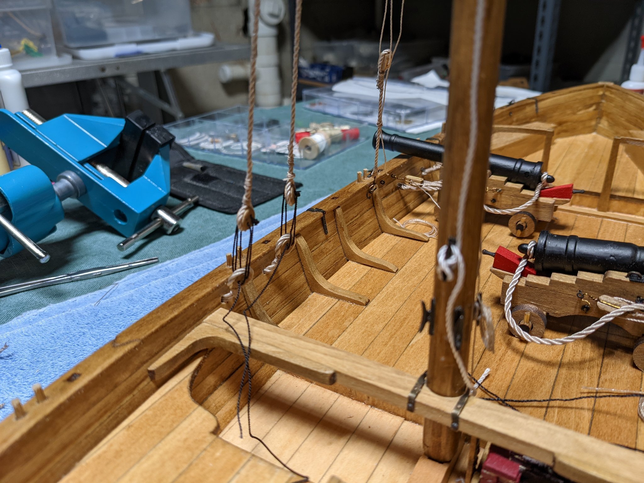
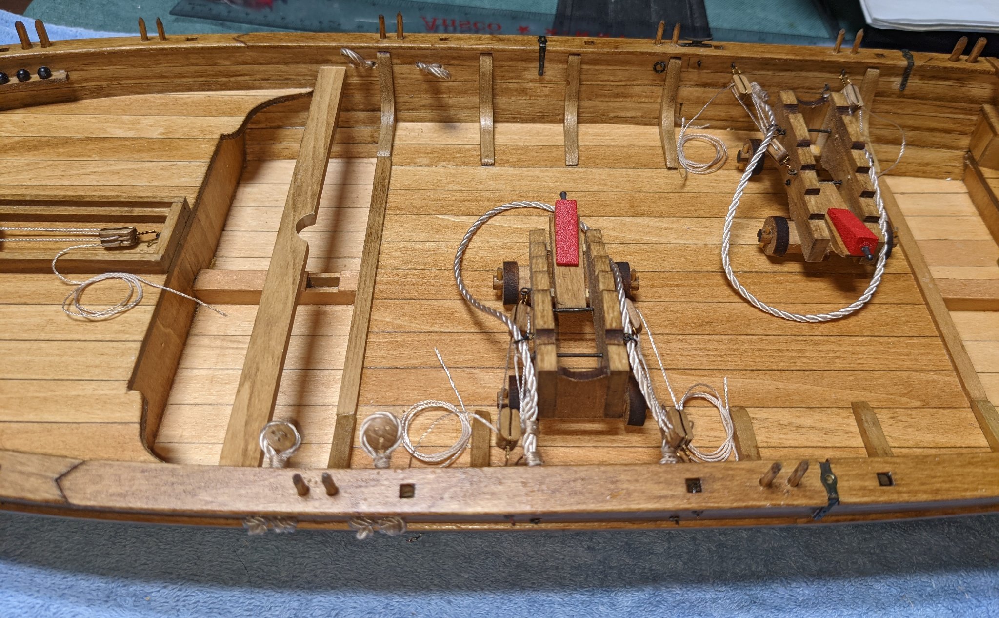
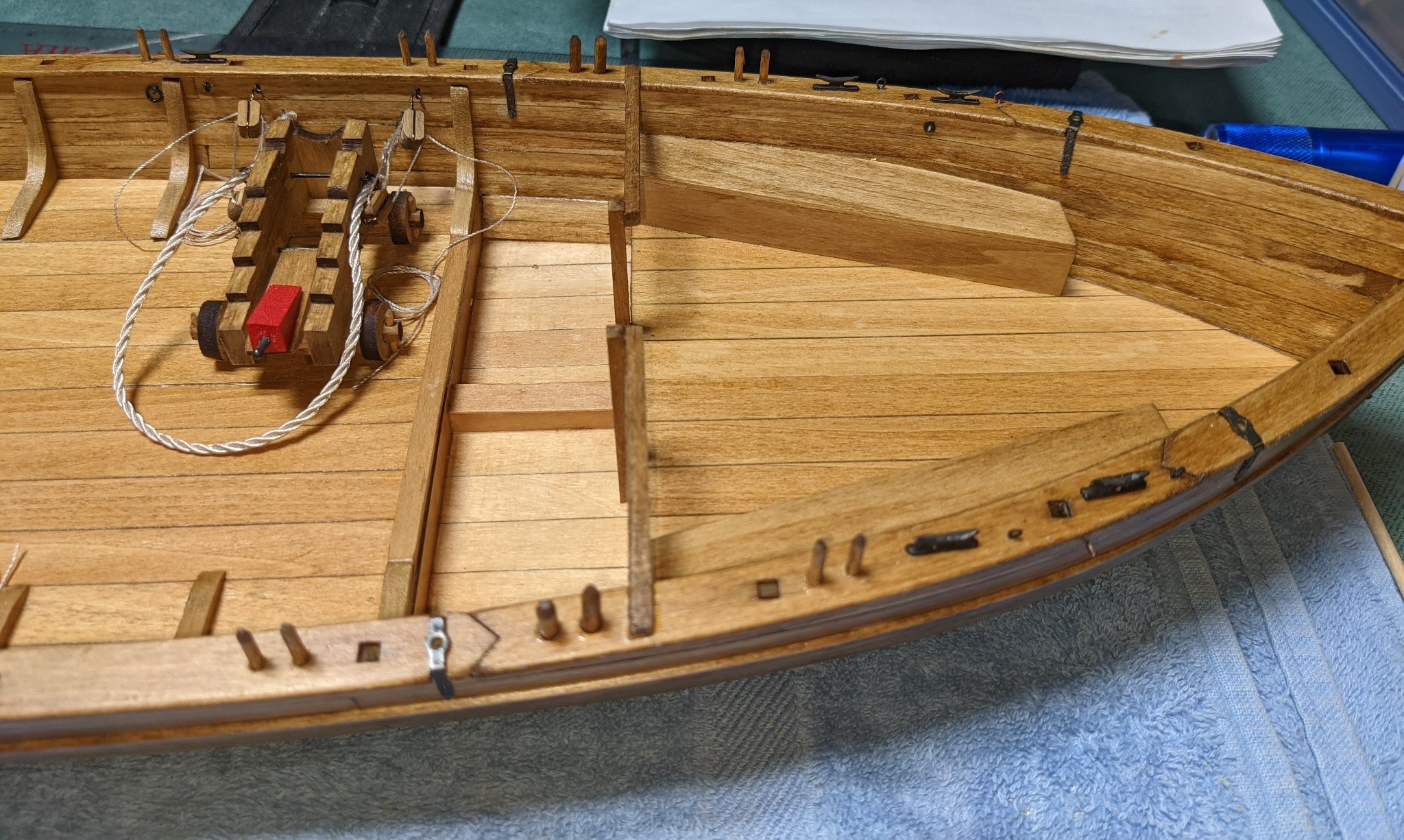
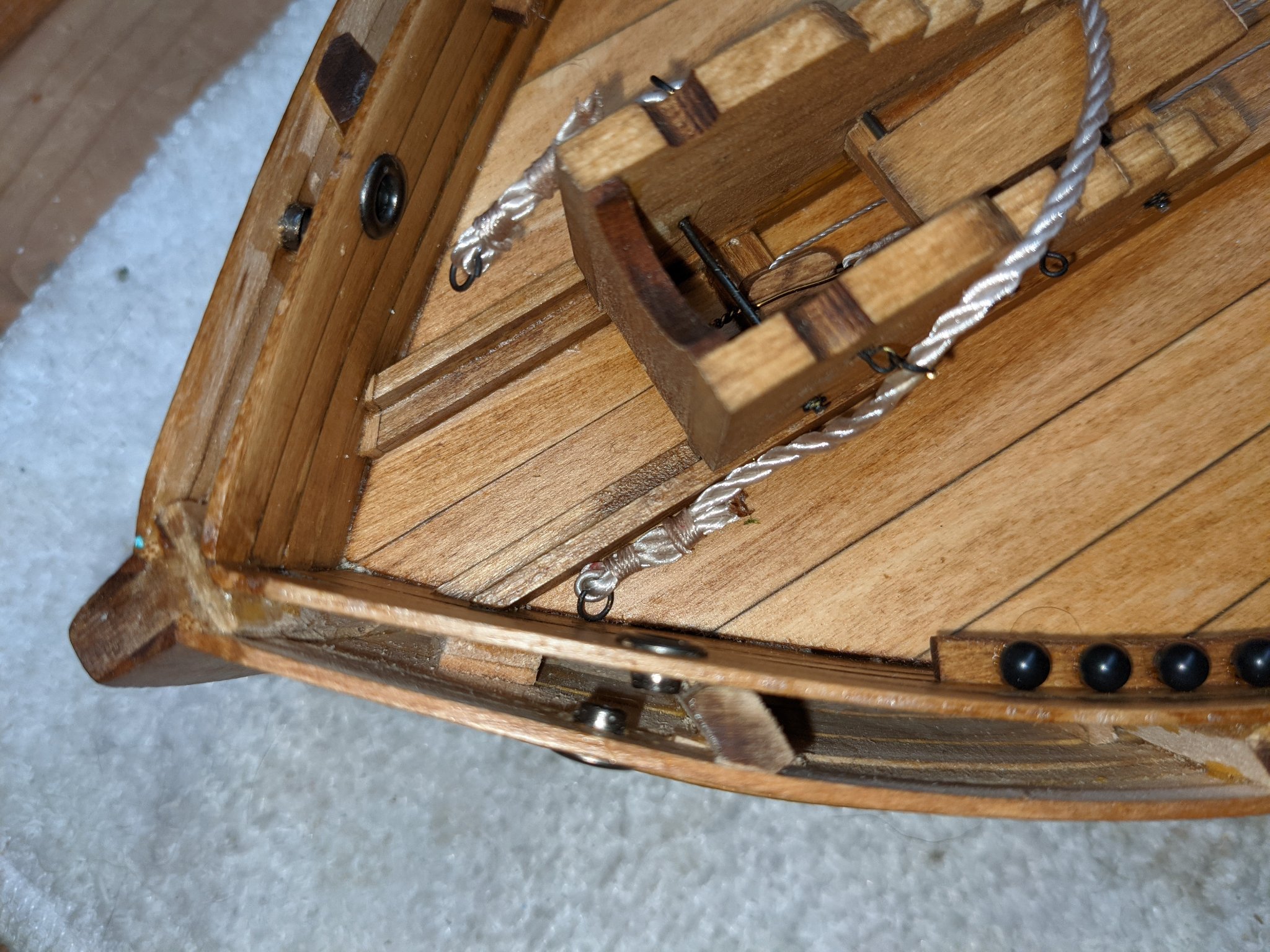
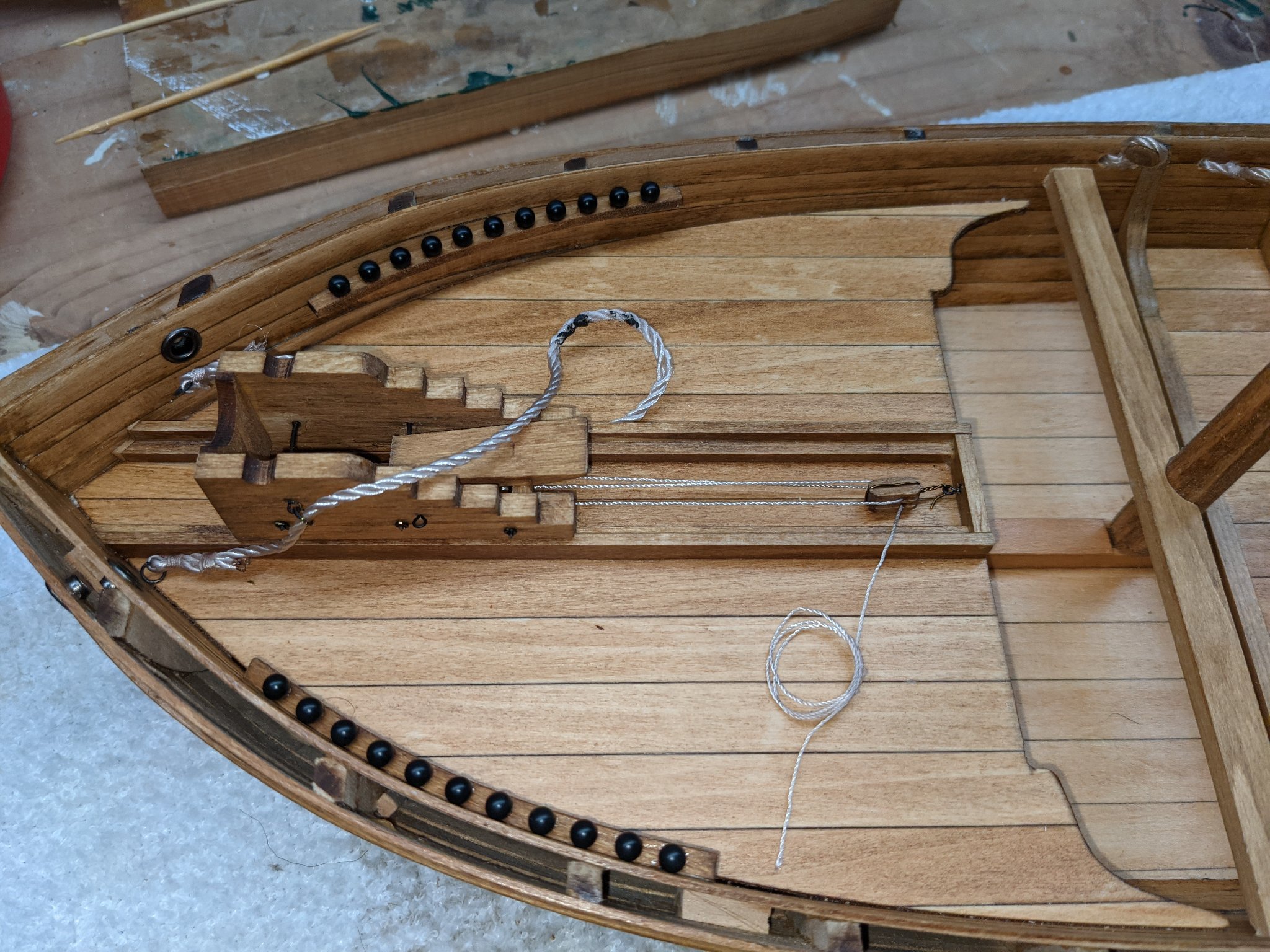
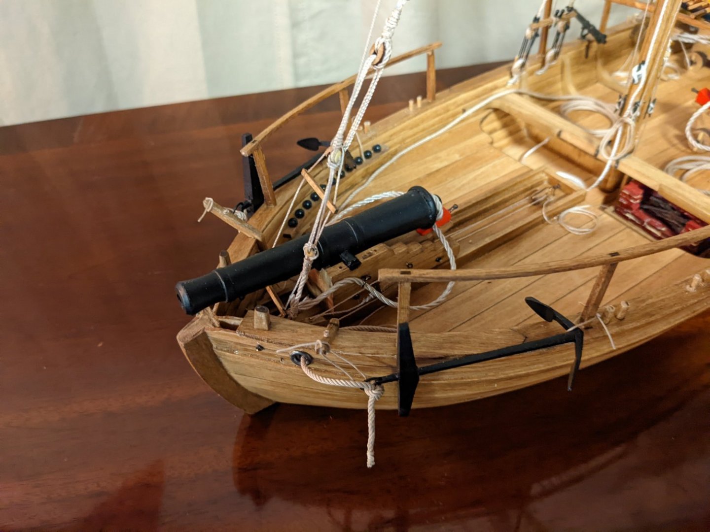
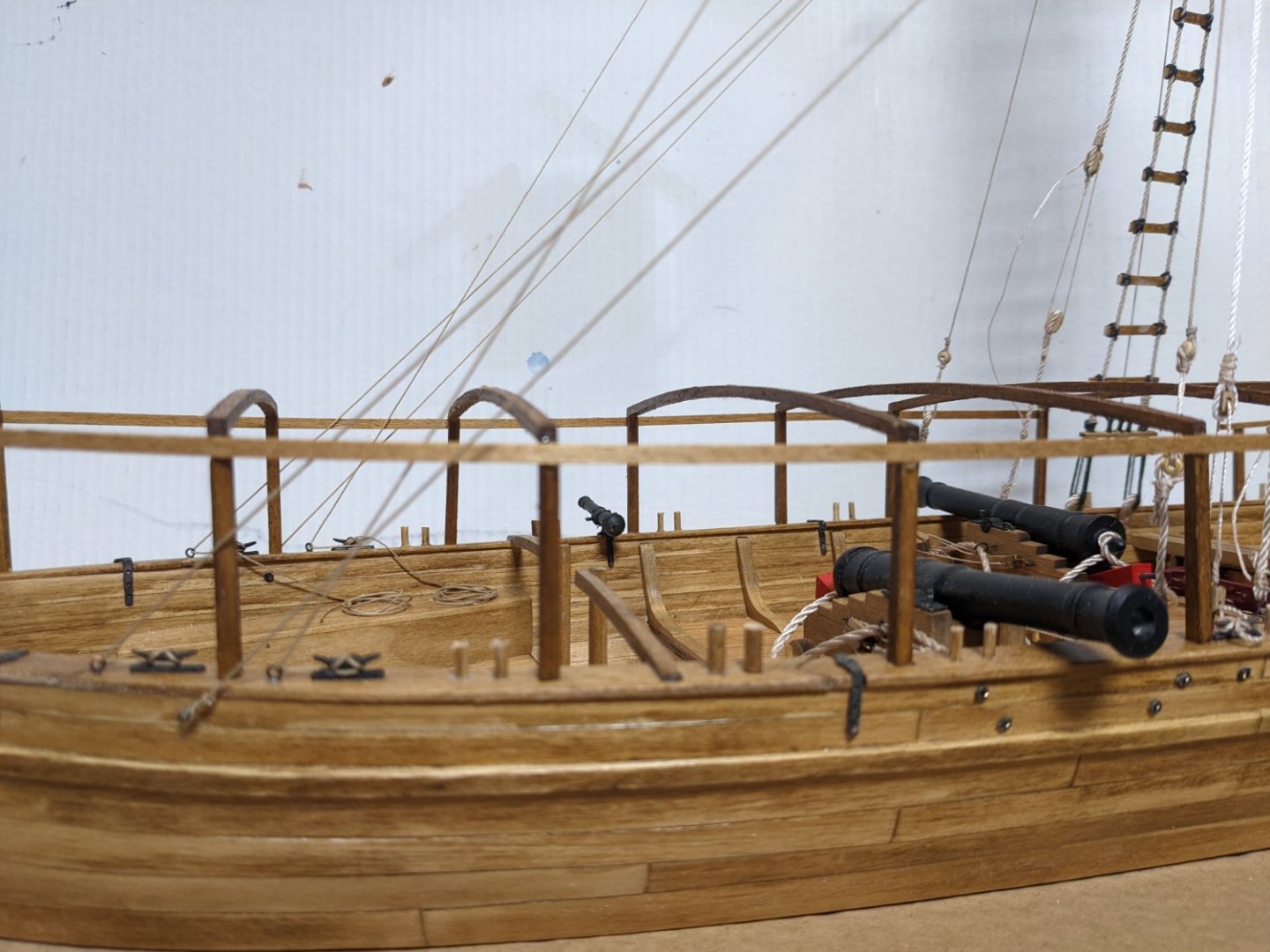
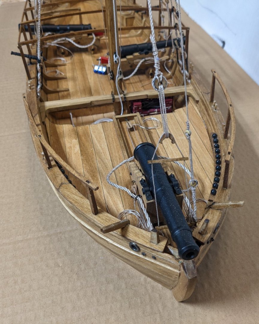
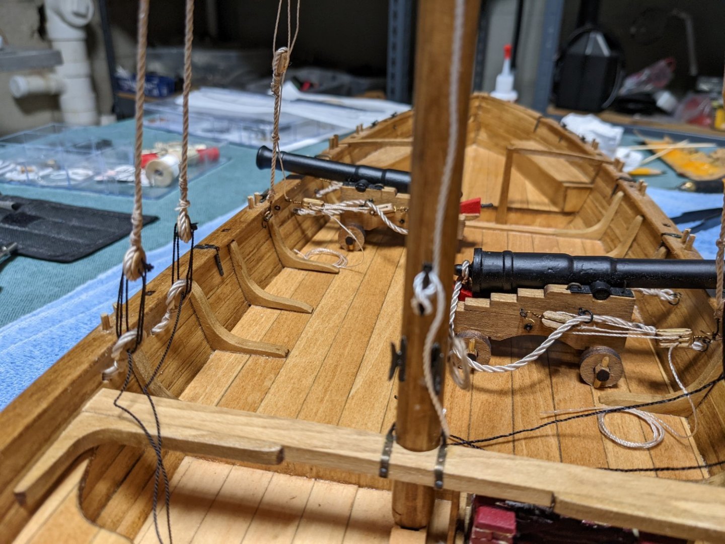
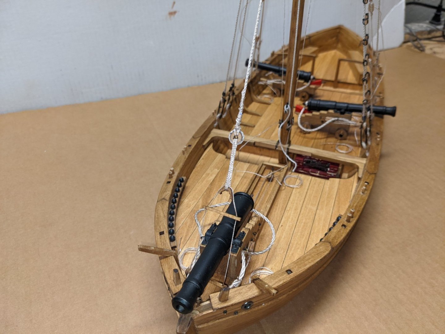
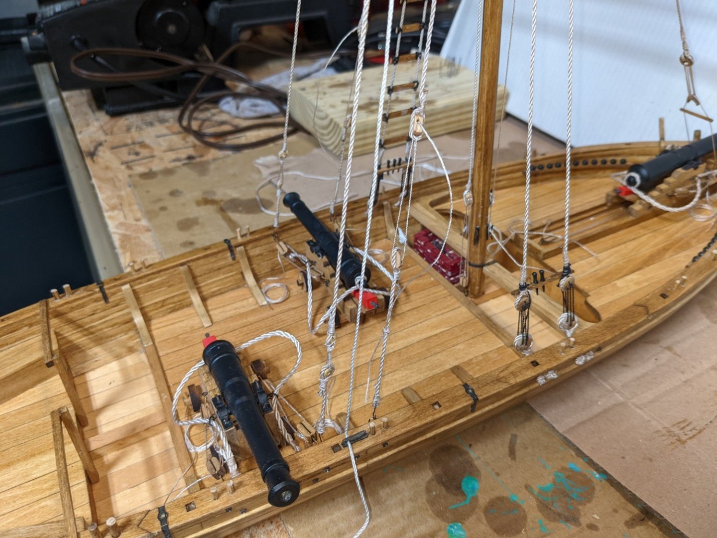
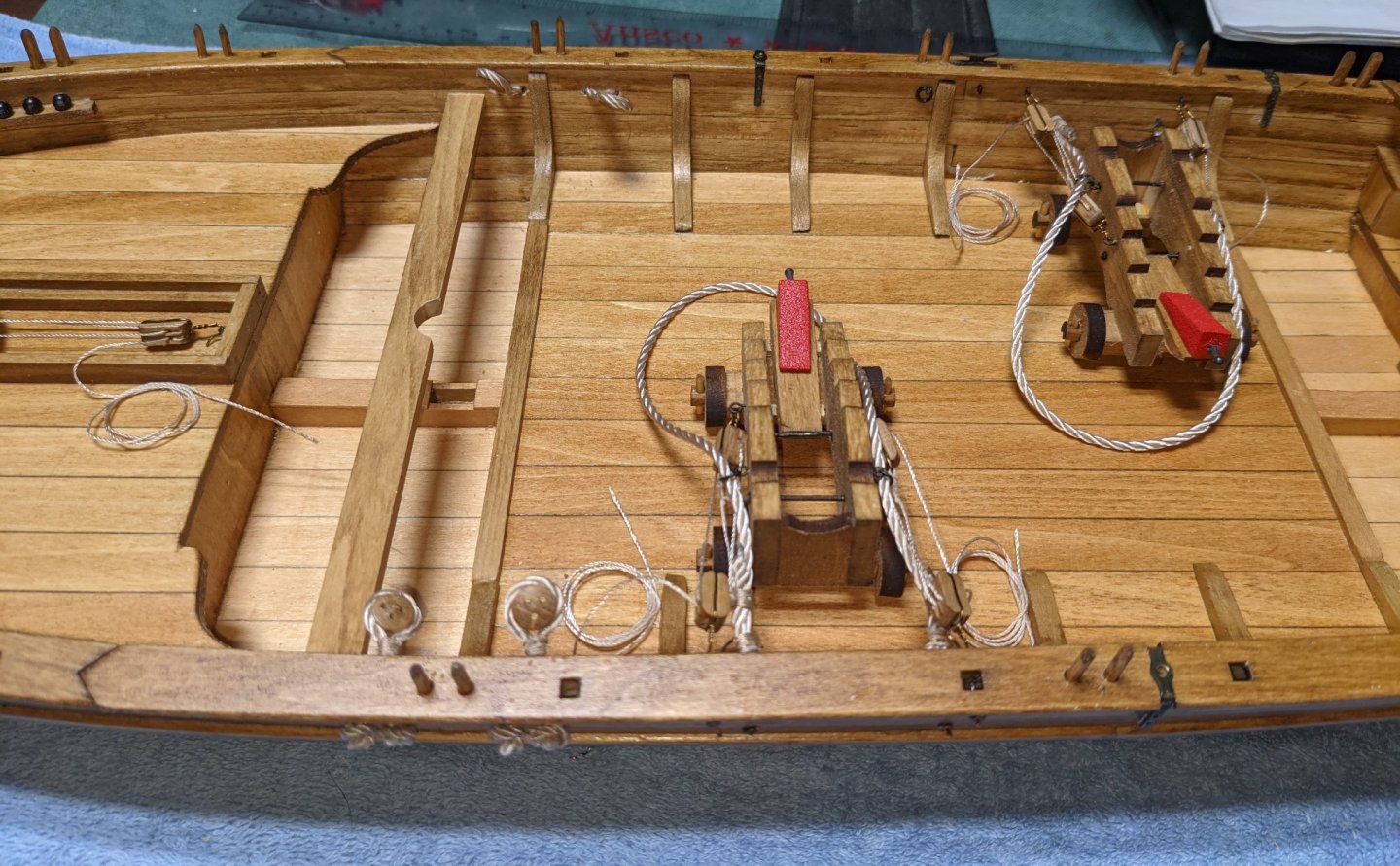
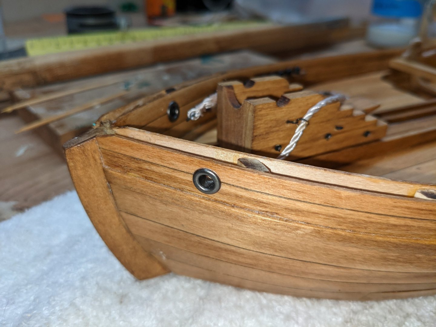
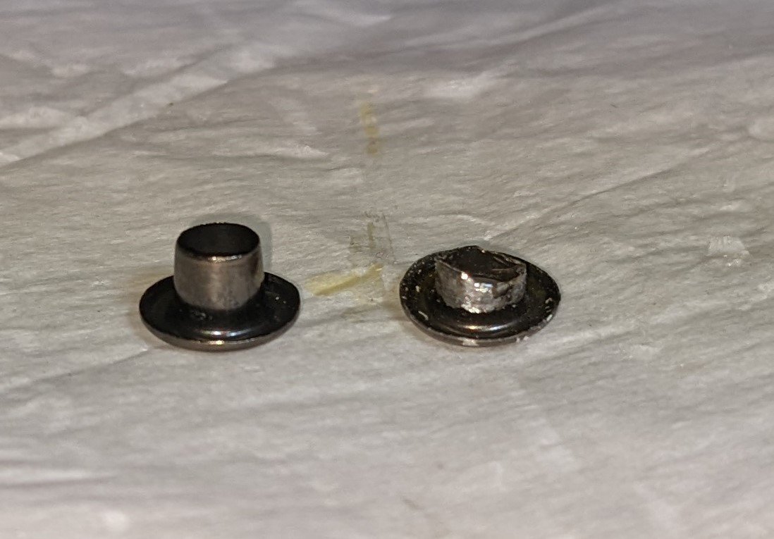
Below show the two 9lbs canons fully rigged minus the canons Bow shot showing the 12lbs canon as a work in progress. The black on the breeching rope is from the 12lbs canon. Originally I attached the breeching line to the 12lbs canon with a little glue. I then (actually read the instructions) realizef it was best to remove the canons until later in the build so as not to get in the way or get knocked around during the build. When the breeching line is again attached to the canon, it will not be noticeable I also found some small black marbles for the shot garlands Rather the using the supplied brass rings for the hawse holes I decided to use 4mm grommets. One on the inside and one on the outside. To me they look a little better and must easier to install than the brass rings. The rings are very small and trying to get the hawse hole just right for the rings to cover seems like a lot of effort for no gain. Next two shots show the hawse holes from the outside and from the top before the rail caps installed. Note in the picture above the two grommets. While grommets are a good idea, there will be no way to string the anchor line from outside in once the rail caps are installed. I did not realize this until I look them from this top view. One solution is to string the anchor line now while you can still get to it from the top. Not sure I wanted to do that and have the anchor line just sitting there until late in the build. Instead I pulled the grommets out, filed them down and re-inserted them again. Below shows a full grommet and a filed down one. This way, once the rail caps are put on, it will be easier to string the anchor line between the offset grommets. Not really sure this was easier than stringing the anchor line at this point, so decide for yourself what is best for you. Instructions call to trim and install the mast partner way before building the mast. Since the mast partner has to be trimmed to fit the hull and the mast, it seemed like a good idea to complete at least the bottom mast before installing the mast partner. As every model is a little different, and do to my lack of skill, I really wanted the mast to help with the positioning of the mast partner. Instructions calls for building a jig to help position the mast partner, but still, I wanted the actual mast to be part of the mast partner trimming. Otherwise, if the mast partner is a little off, (do to lack of builder skill) when you go to fit the mast, the mast may not be straight. By using the jig and actual mast, you have a good chance to getting the mast straight up and down. Mast is not permanently attached at this time - just used to help position the mast partner.


- 36 replies
-
- 3
-
-
- Model Shipways
- Philadelphia
- (and 1 more)
-
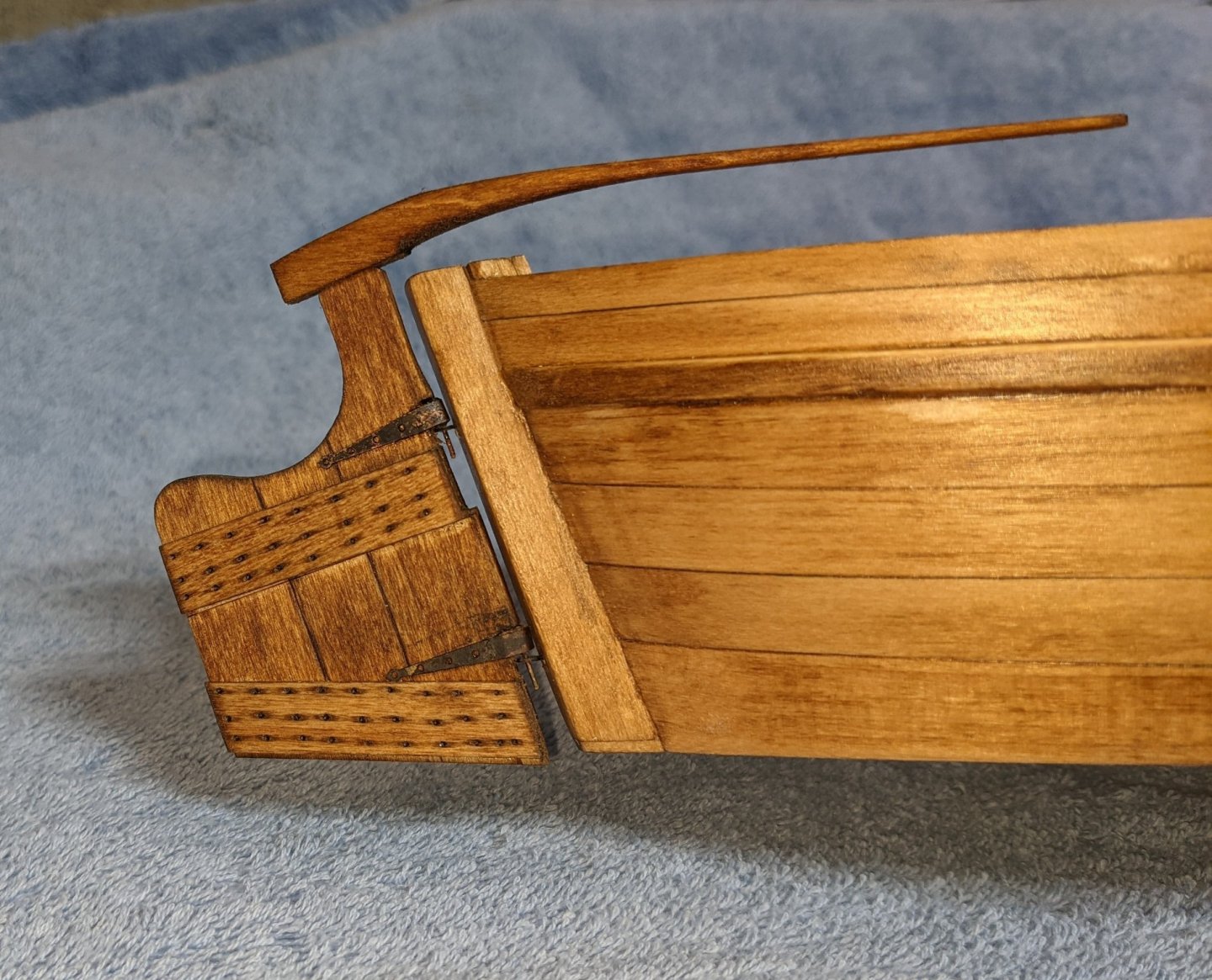
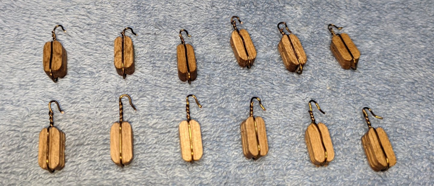
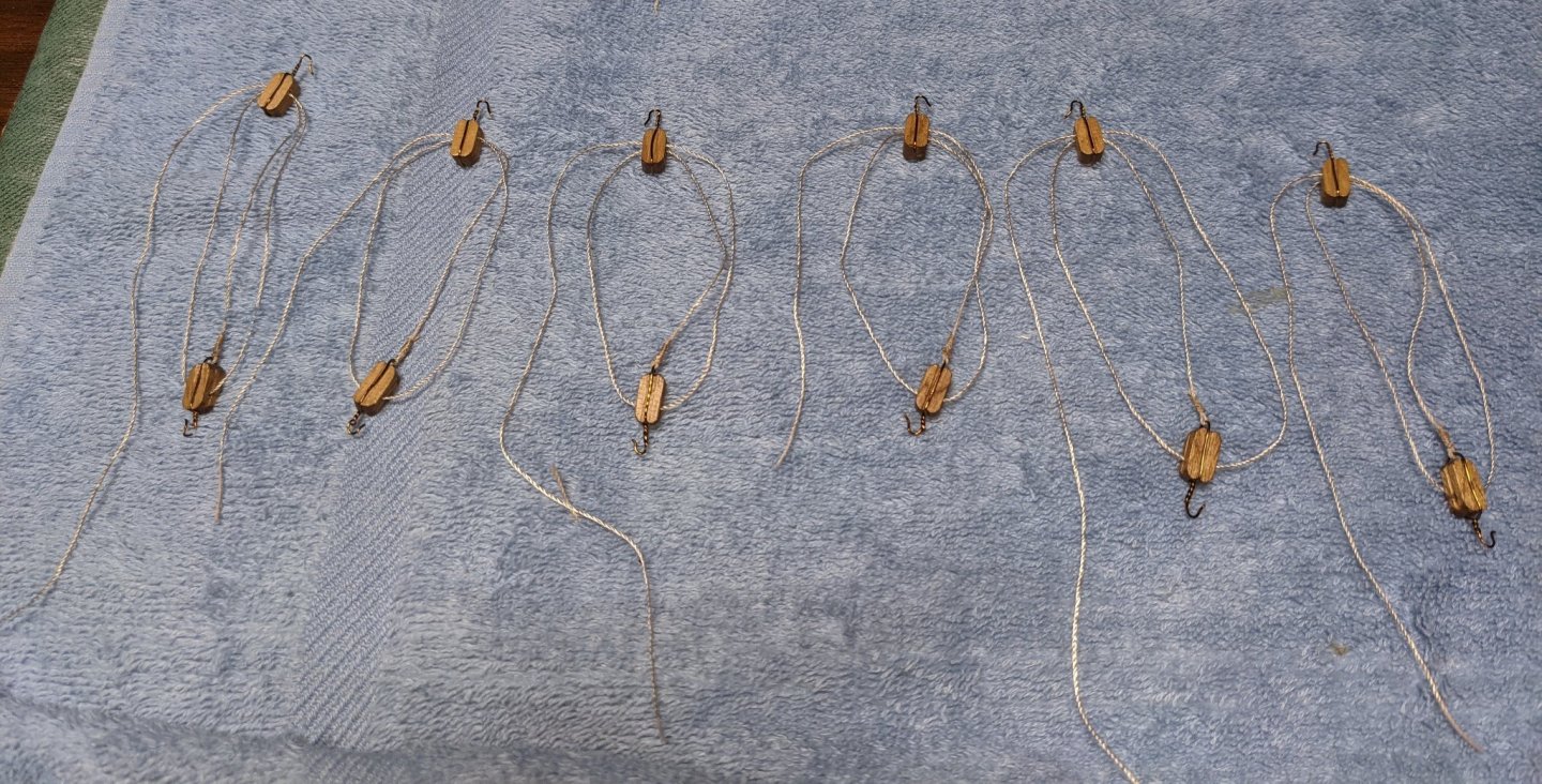
Decision made. According to the instructions one is supposed to run the deadeye lines through the hull and secure them outside the hull with a "stopper" knot. Realizing it is next to impossible (for me anyway) to tie a knot and have the deadeyes still all line up, I decided to "simulate" the "stopper" knot. After running the deadeye lines through the hull I took the next size smaller line and just tied an overhand knot around the line sticking through the hull, then trimmed the lines to look like a knot. They more or less look like a "stopper" knot. To me they did not turn out too bad.... or the best I can do anyway. At this point I decided to complete the rudder. The challenge here is to solder the pin at the exact center of the gudgeon. Get the solder a little left or right of center and the gudgeon will not fit centered in the rudder. Holding the pin in the center of the gudgeon and then soldering it into place is a lot easier said than done. Be careful as the brass gudgeon is very thin and can not take a lot of filing or re-bending if you did not get it right the first time. Instructions talk about putting the horizontal battens only one side of the rudder. Purest may disagree, but to me the rudder looks better with battens on both sides of the rudder... That is what I ended up doing. Started rigging the canons. As for stropping the single and double blocks, since they are canons, I decided to strope them with wire. Where the line attaches to the becket on the single block I did strope with small line. Below is my attempt at the single and double blocks used to rig the 9lbs and 12lbs canons. Single blocks are on top (with the becket) and double blocks are on the bottom. From there is was pretty easy to string up the canon rigging. I did this outside the hull, so only need to hook them and tighten up the lines to complete the install.
- 36 replies
-
- 3
-
-
- Model Shipways
- Philadelphia
- (and 1 more)
-
Joseph There are about as many ways to blacken brass as there are model builders. If you look on MSW logs, lots of folks have various ways to do it, with mixed results. Some successful and some not so successful. I have found (not that I am anywhere near an expert) that Novacan works great for blackening etched brass. See my post on my Philadelphia, it shows some results. You can use it full strength to get a really rustic brown/black look or use it 1/2 strength to get a more even blackening. john
-
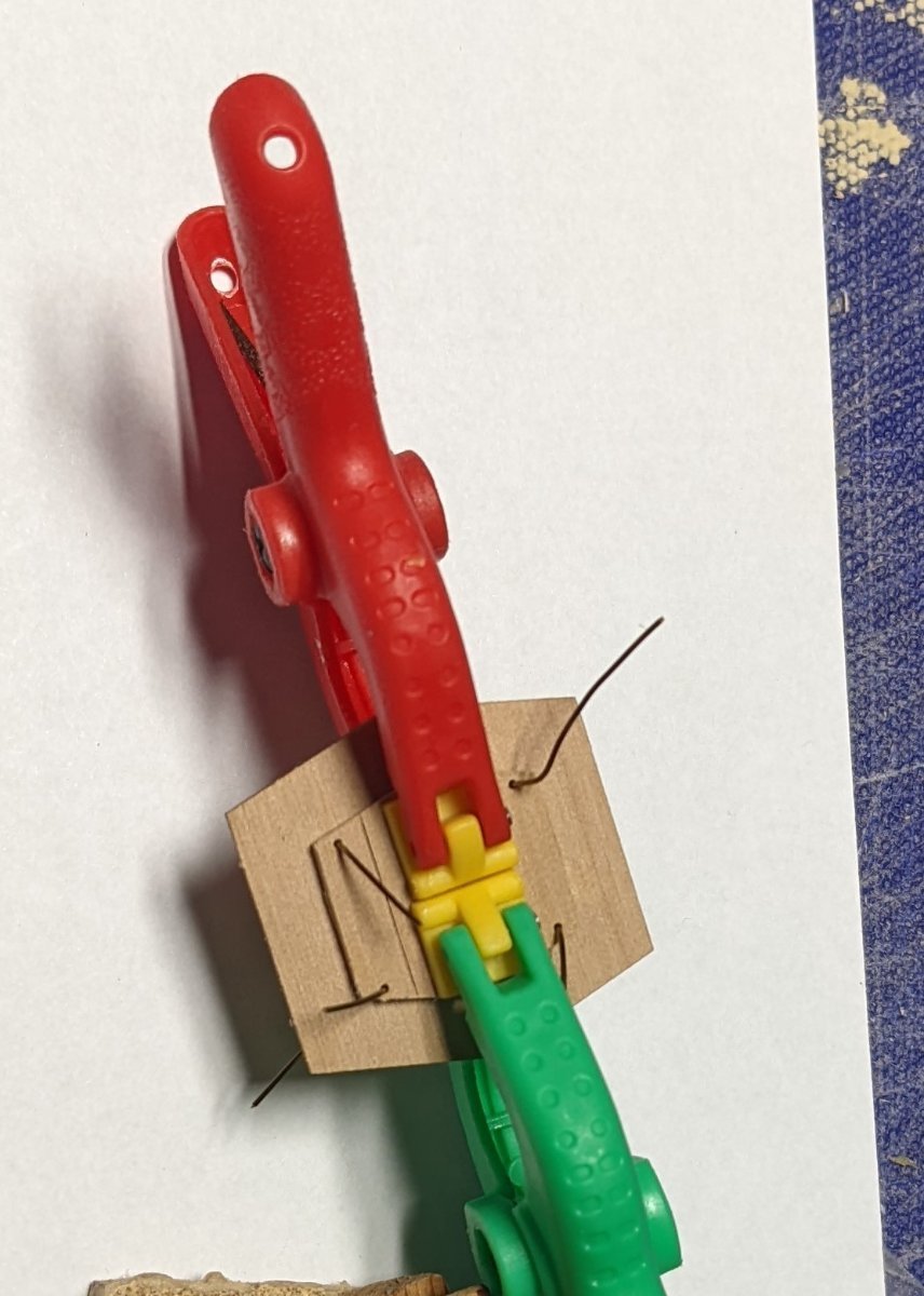
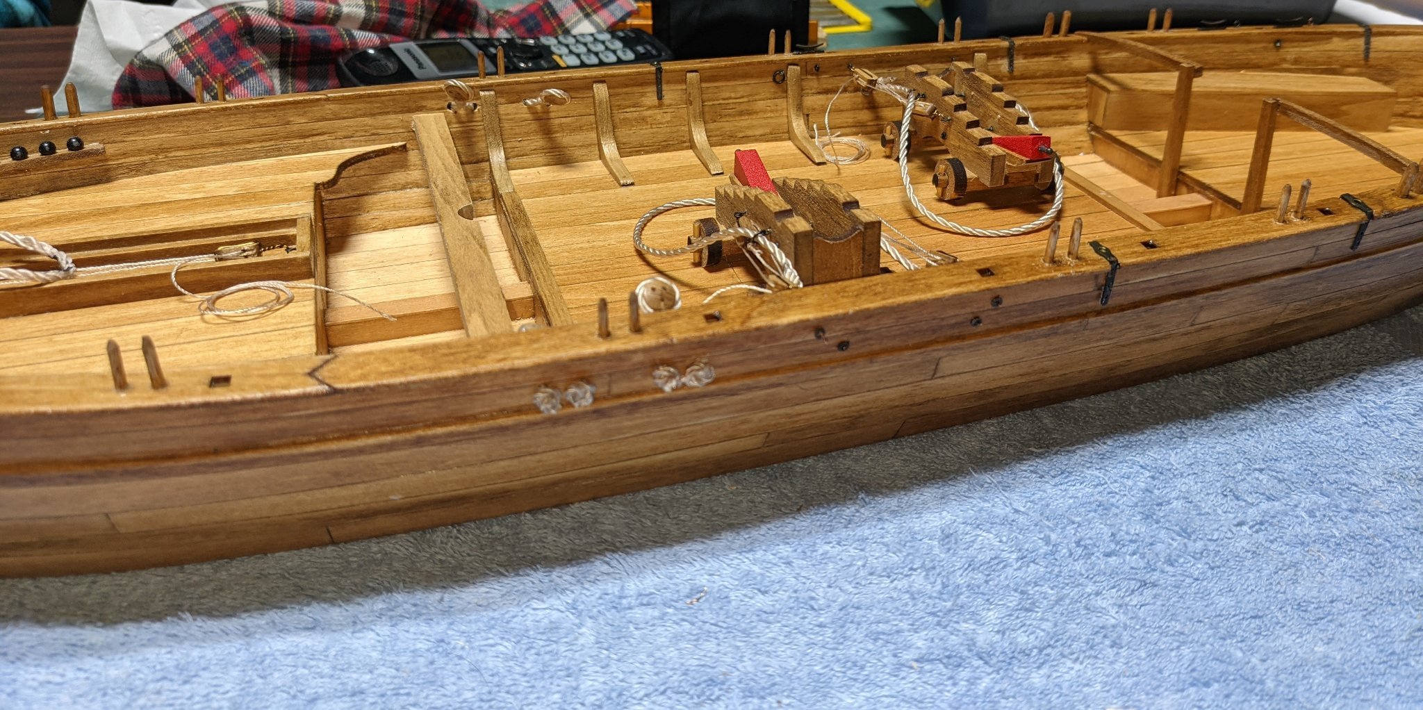
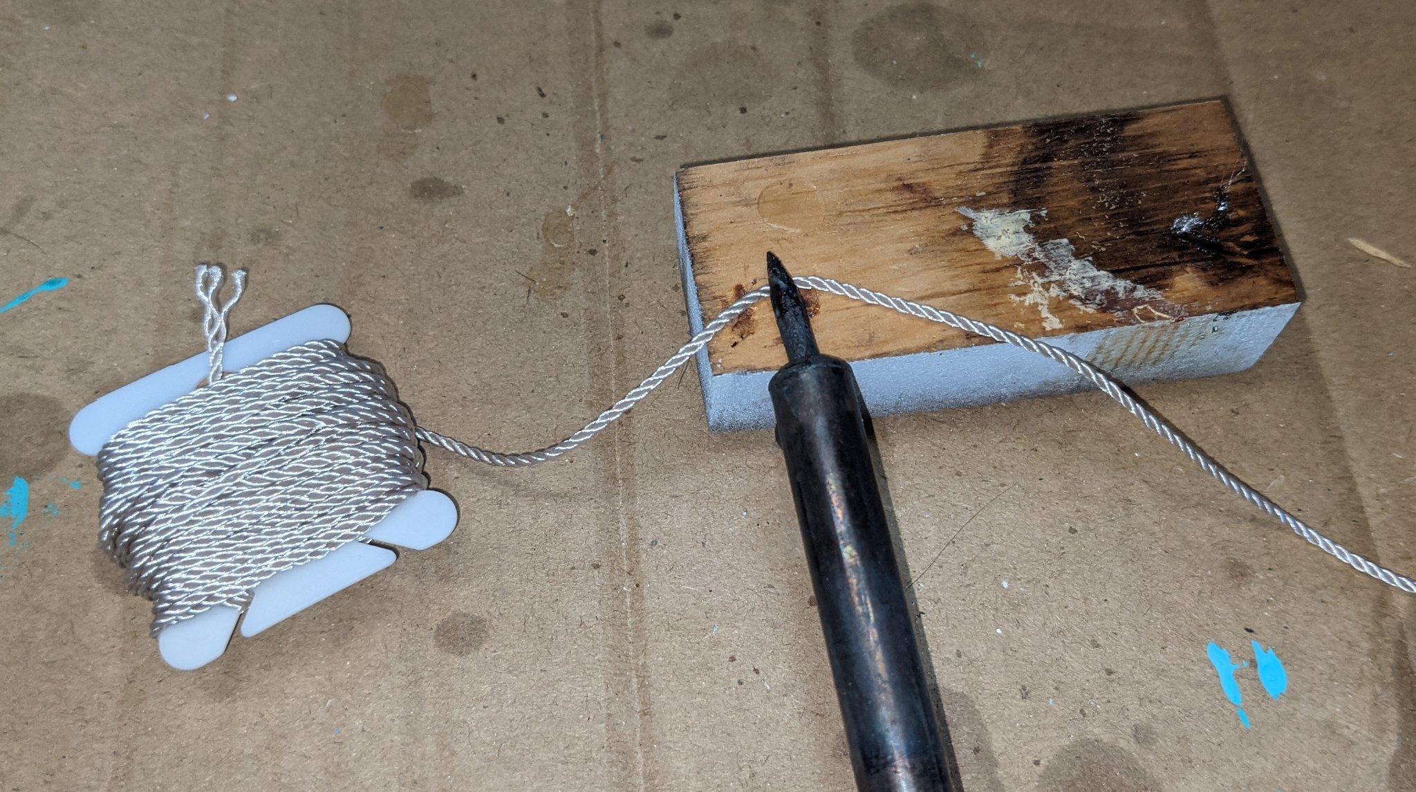
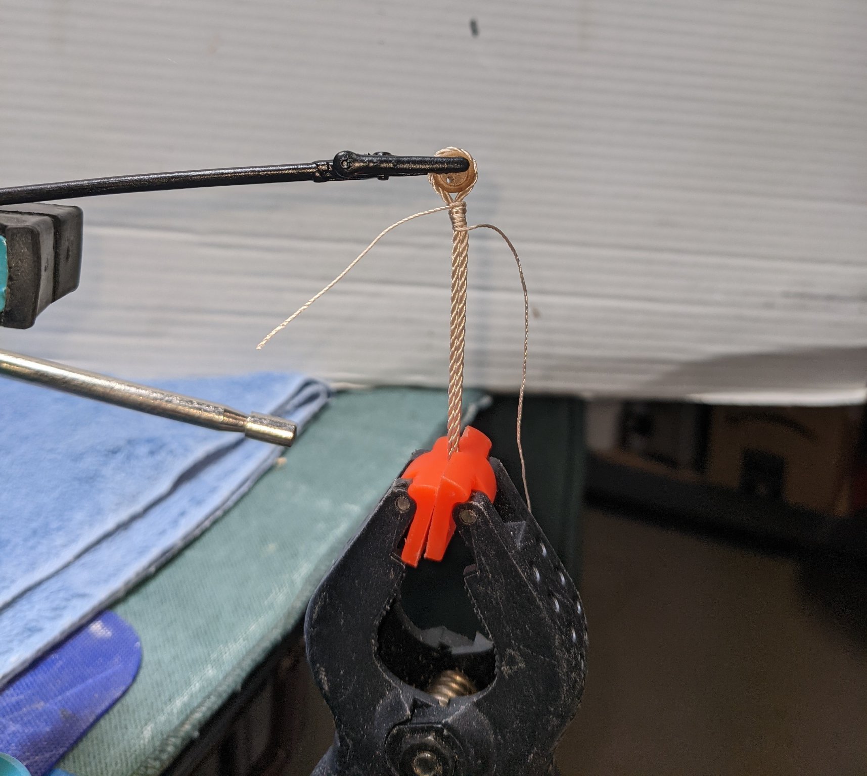
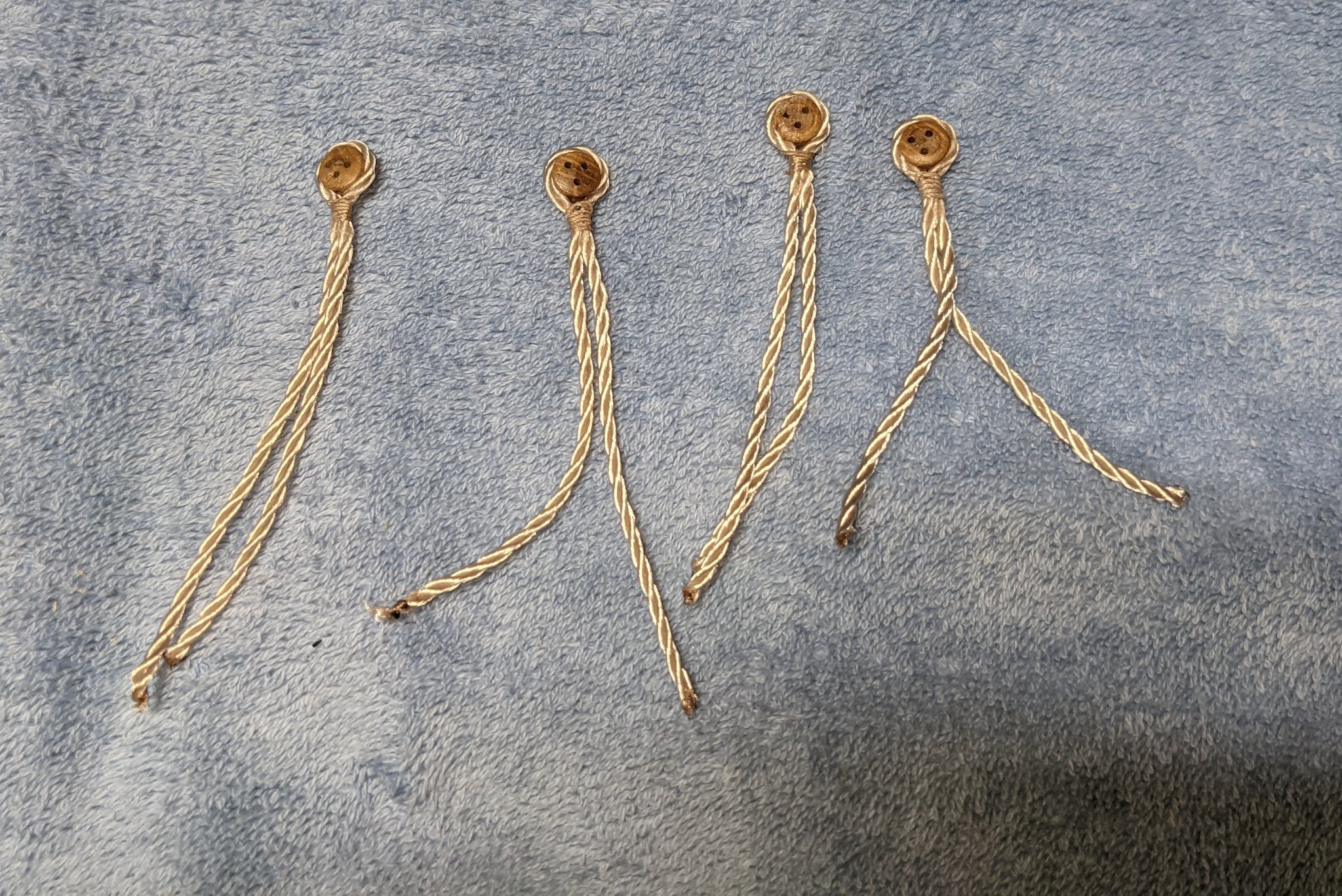
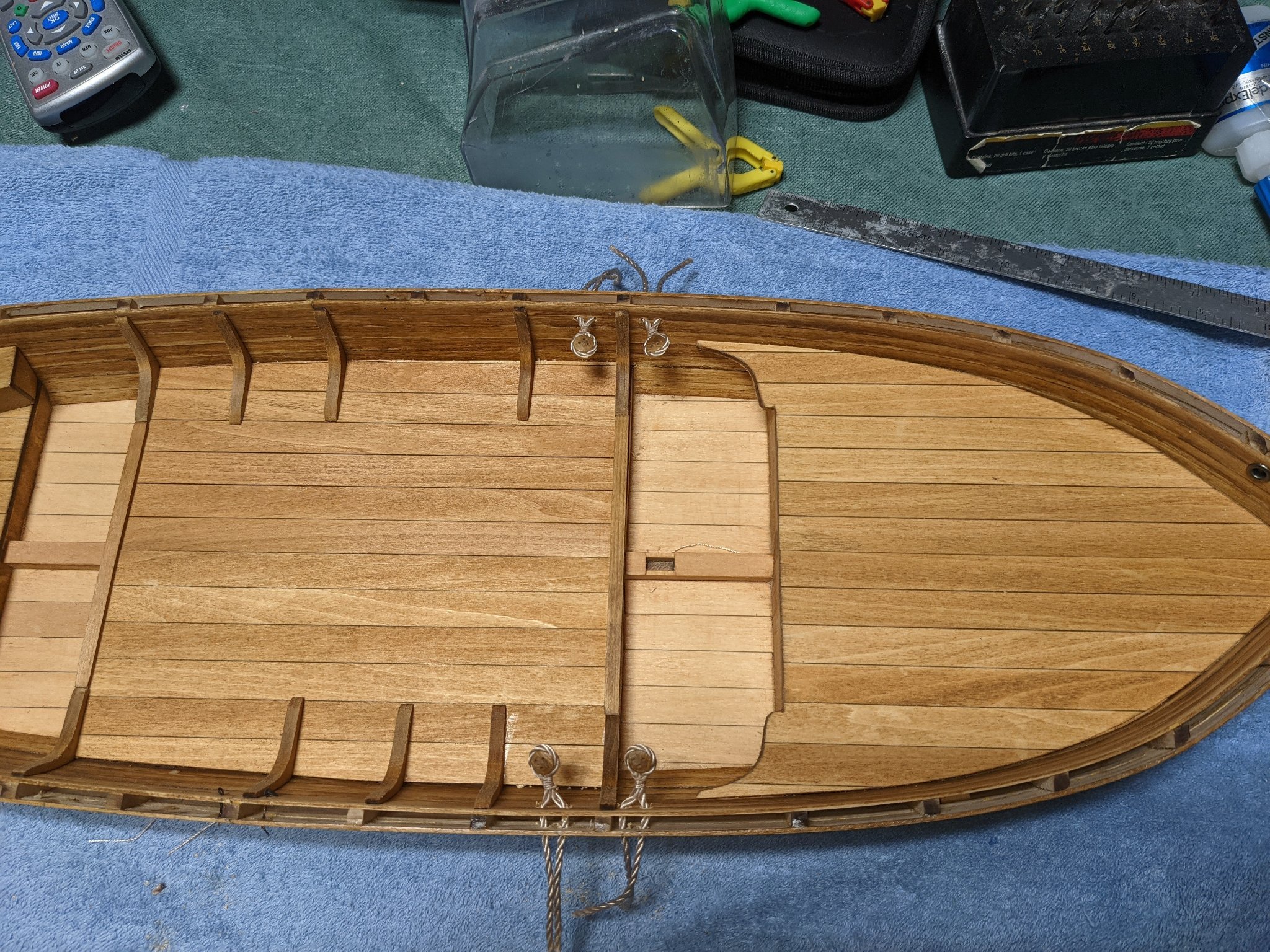
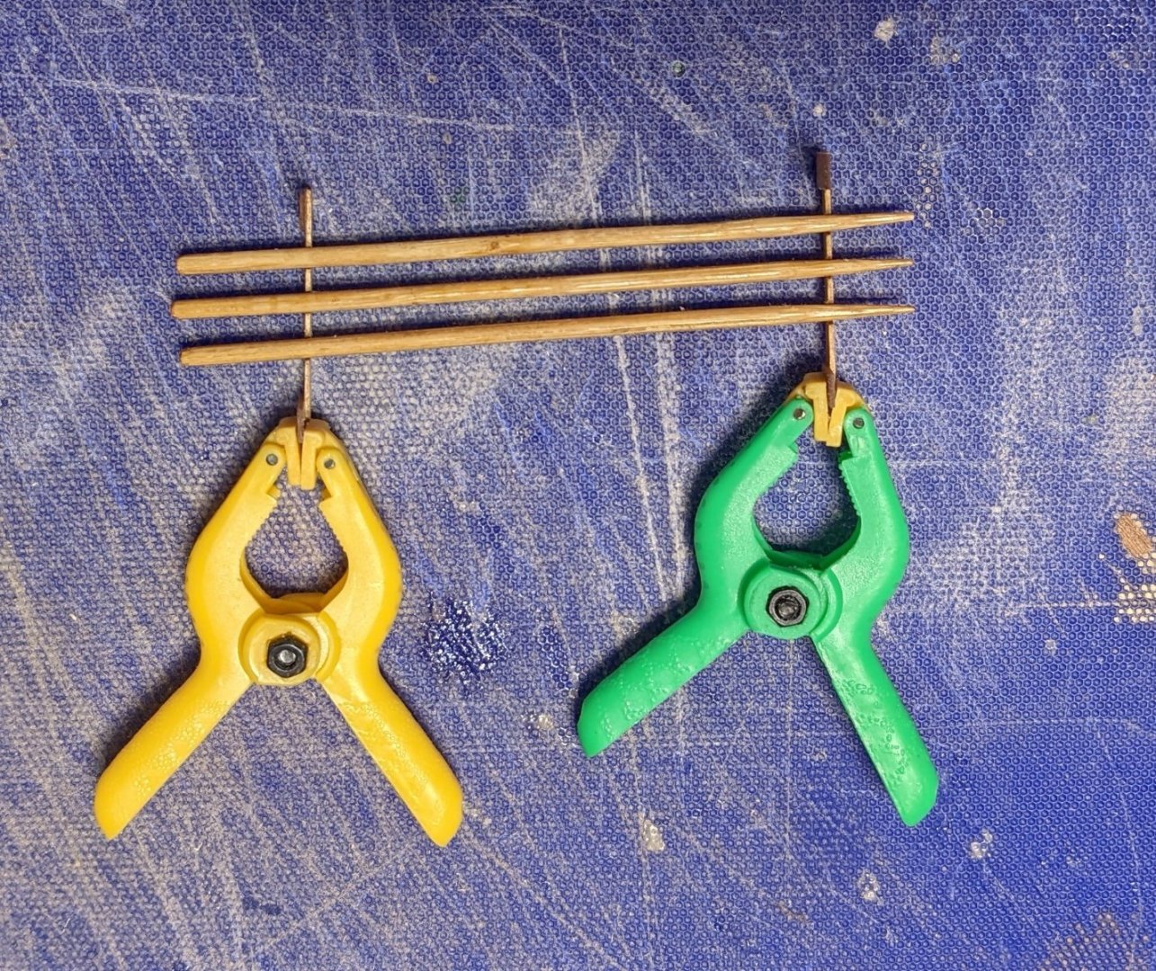
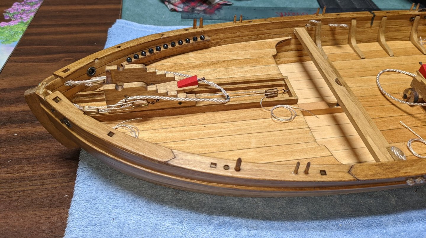
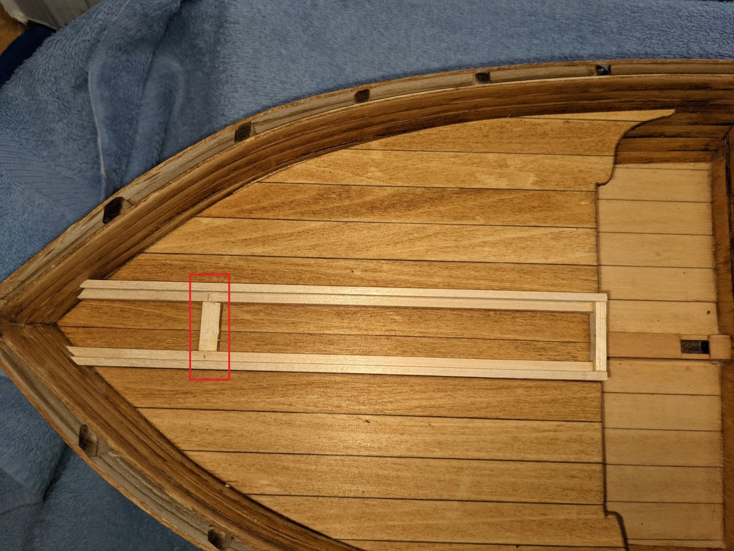
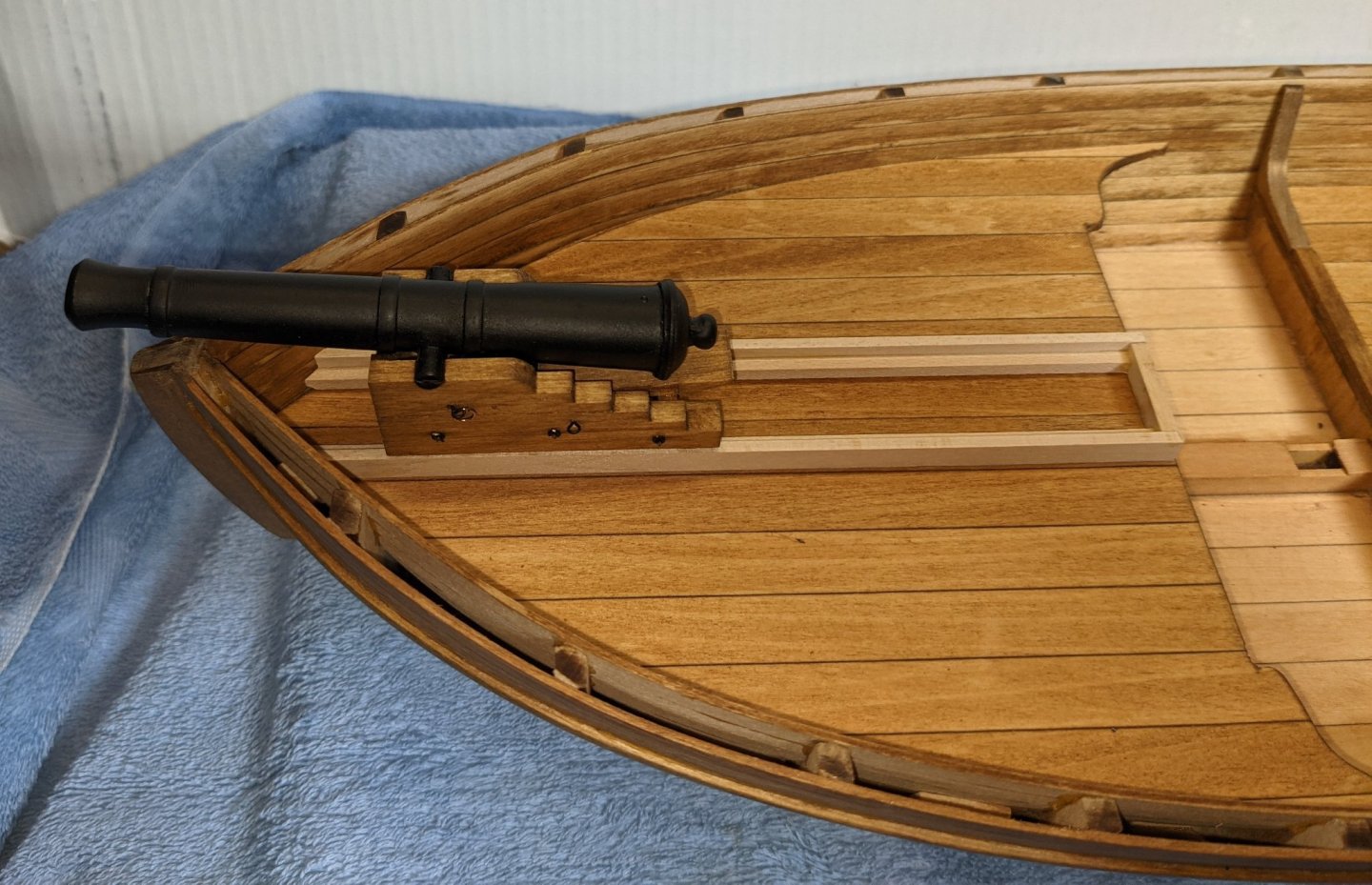
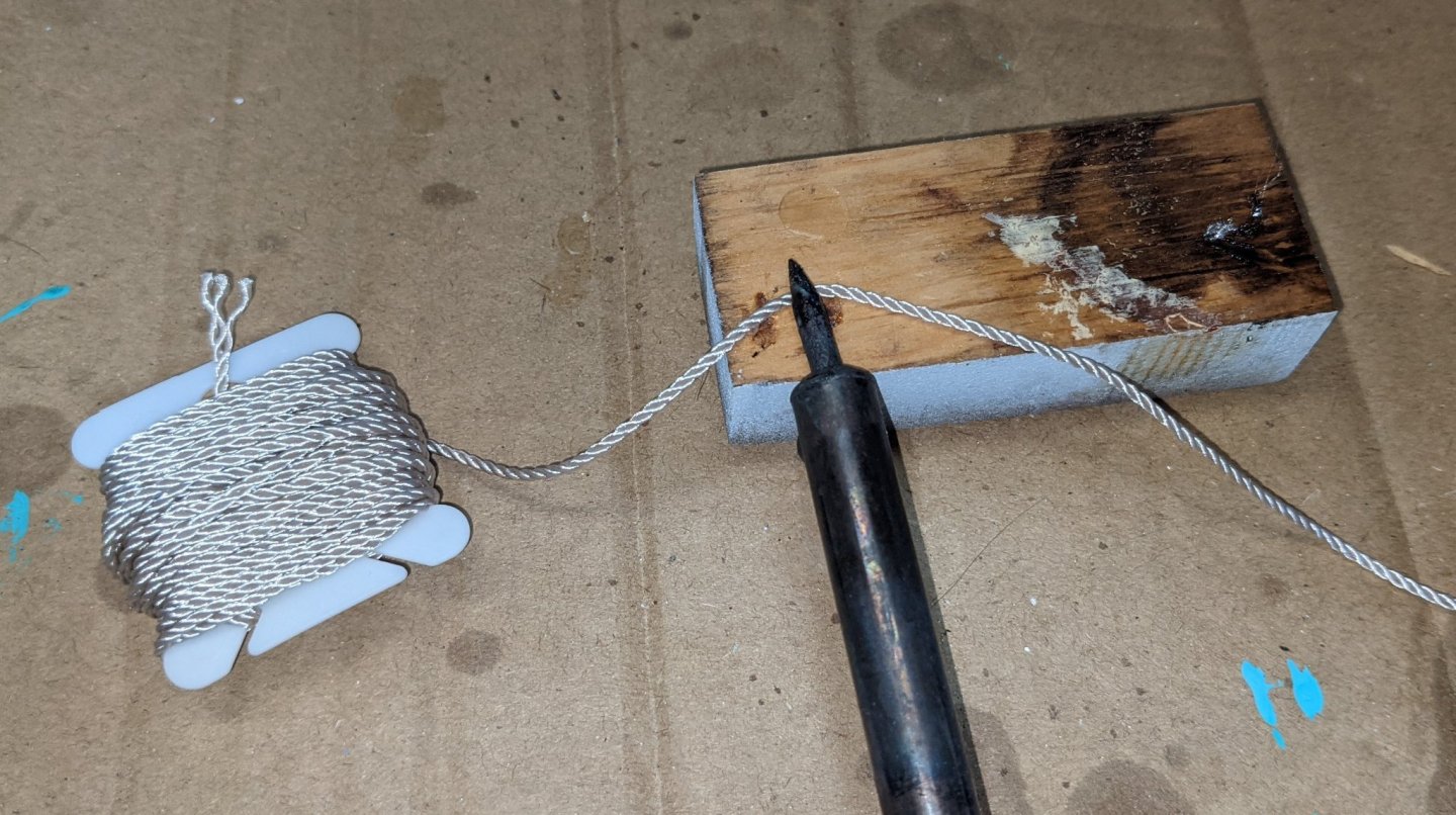
Been some progress to date... It is summer and just too hard to be indoors building... I ended up using Golden Oak for a stain on the hull and light sanding afterwards to "dull it up some". Aft storage chests and knees have been installed too. In addition all hull holes have been drilled and those that are to accept eyelets at this time have been installed. I got a little anxious and moved on to the 9 lbs and 12 lbs guns. A little our of order. As usual, the guns needed a lot of sanding/filing to remove the rough edges. For stock molded guns they did not turn out too bad. Both the 9 lbs and 12 lbs gun axles are pretty straight forward to build. For the 12 lbs gun track I did alter from the suggested plans. There are two G6 parts (along with some stock wood) that make up the 12 lbs gun track. Only one G6 is supposed to be glued in. The other one (highlighted in red) is supposed to be used to temporarily hold the proper spacing as the glue dries. For me I found it easier to trim the "temporary" G6 piece so it fits between the tracks and actually glue it to the tracks. This way the entire track can be built/stained outside the boat and then fitted/trimmed and glued into the boat. This now permanent G6 piece will be hidden by the 12 lbs canon. For me I just found this easier. Below shows the canon in what will be it's final spot hiding the glued G6 piece. Track has yet to be stained below. Moved on to the deadeyes.. One note.... the various string supplied with the boat is a shiny nylon that unravels just by looking at it. Not good way to cut it with a knife or scissors without an unraveled mess on your hands. To me, the best way to cut this line is with a soldering iron. With the soldering iron hit, just touch it to the line and it will cut it like butter leaving both ends neatly melted with no unraveling. Best way to strop the deadeyes (for me anyway) was to hang them from an alligator clip with a larger clip holding the line tight. From there it is pretty easy to stop the deadeye Here is the end result of the four deadeyes. I am not the best deadeye stropper in the world, but they turned out OK Here they are temporarily attached through the hull. Instructions call to permanently glue them to the hull at this point. I have to give that some thought.... Not sure I want to attach them at this time. We'll see


- 36 replies
-
- 2
-
-
- Model Shipways
- Philadelphia
- (and 1 more)
-
Session 3 started today.... You can also access the sale via website (http://www.badgerairbrush.com/) and click on "Special Offers"