John Gummersall
-
Posts
265 -
Joined
-
Last visited
Content Type
Profiles
Forums
Gallery
Events
Everything posted by John Gummersall
-
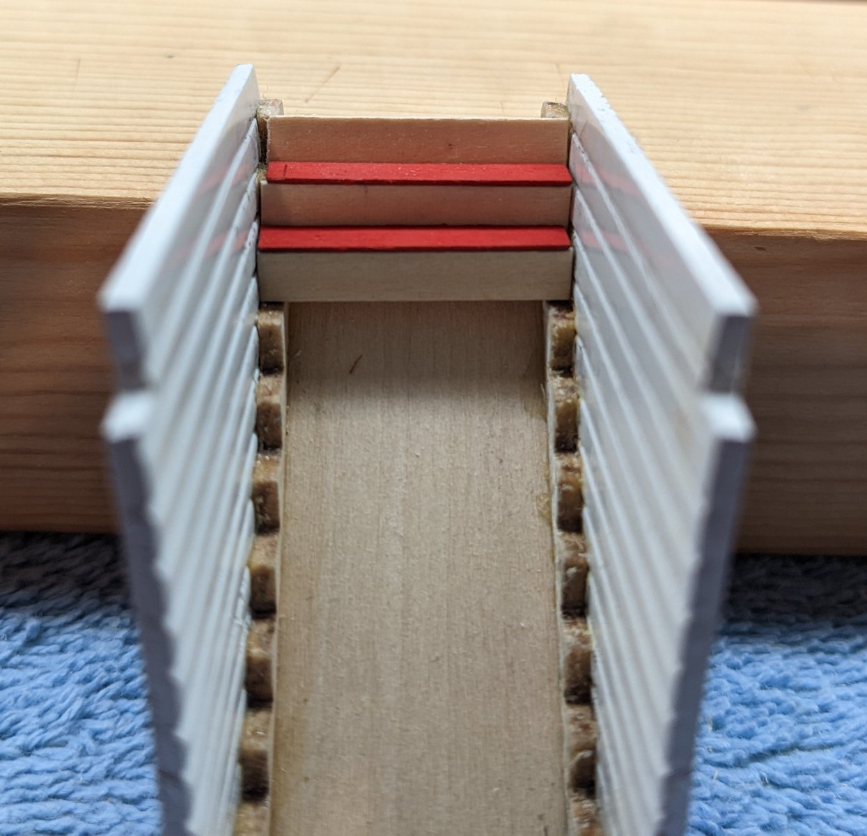
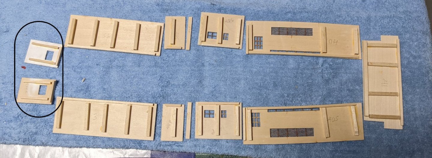
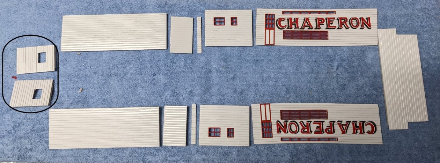
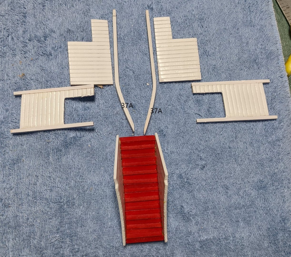
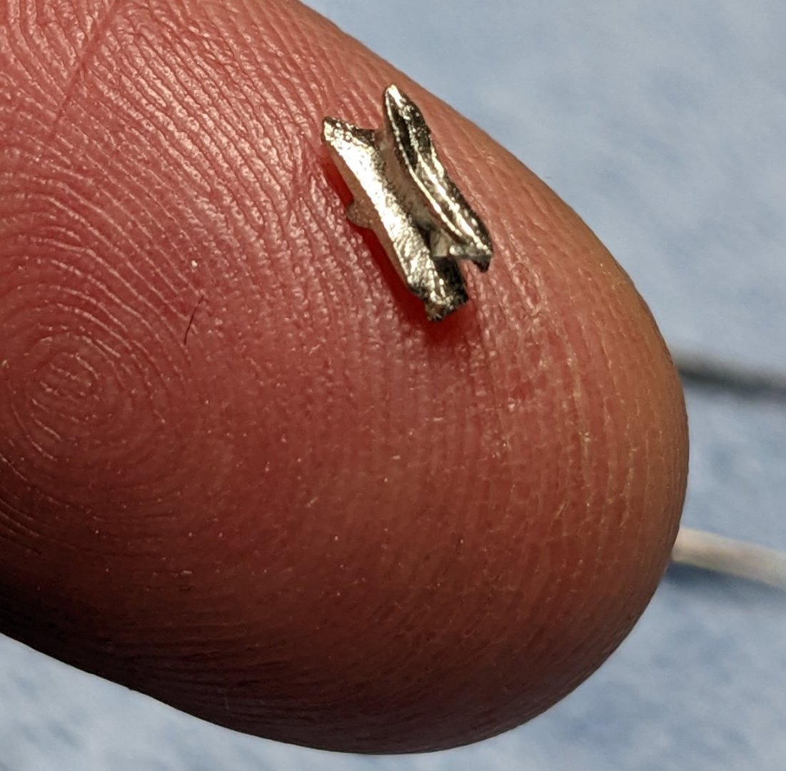
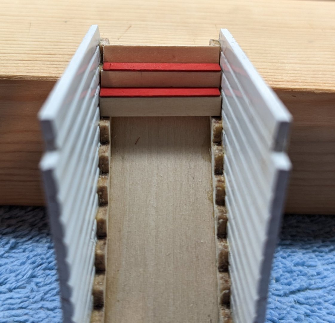
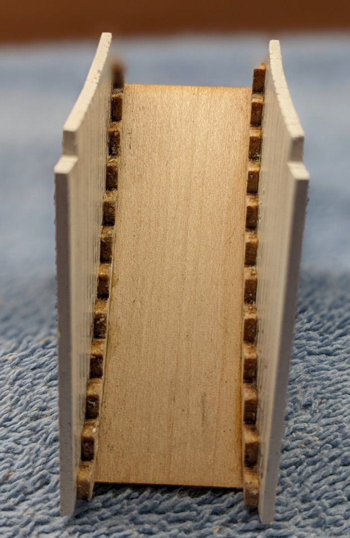
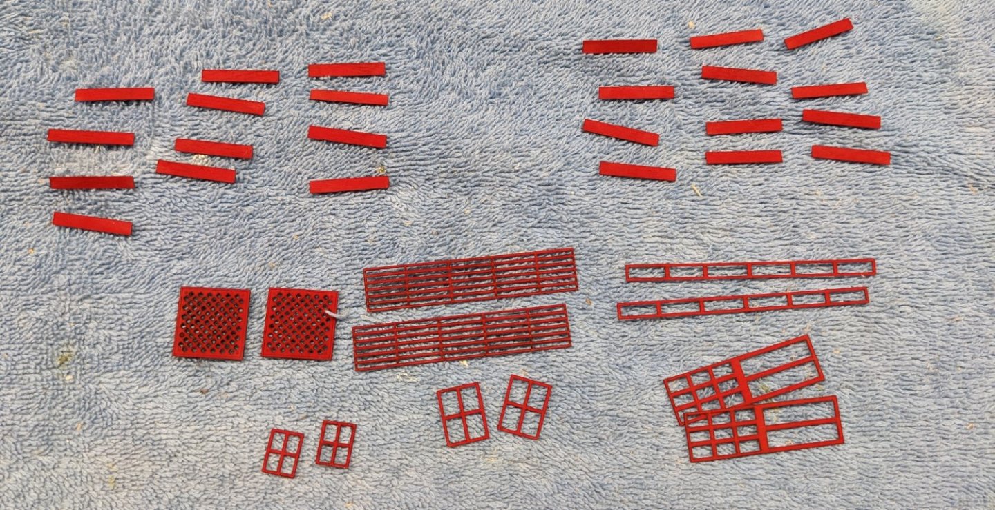
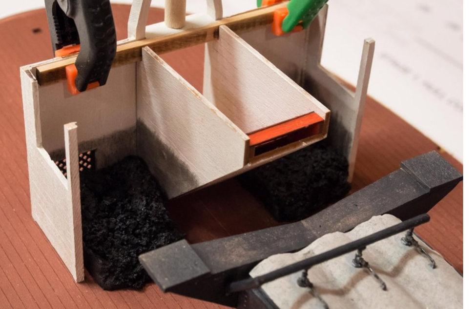
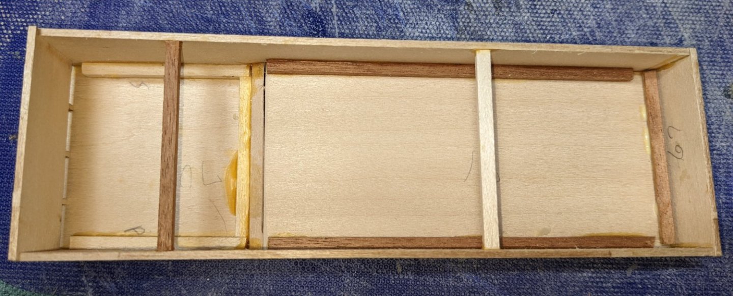
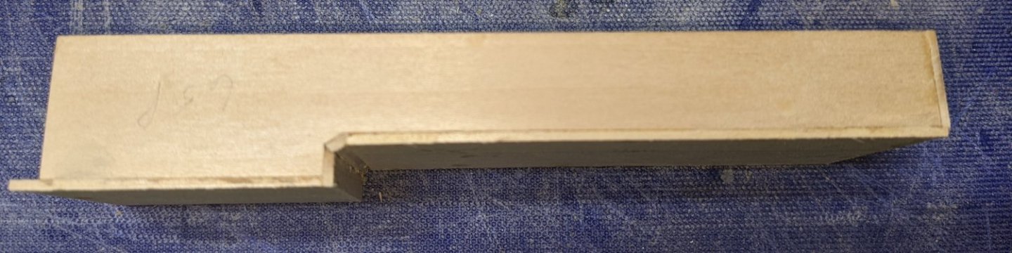
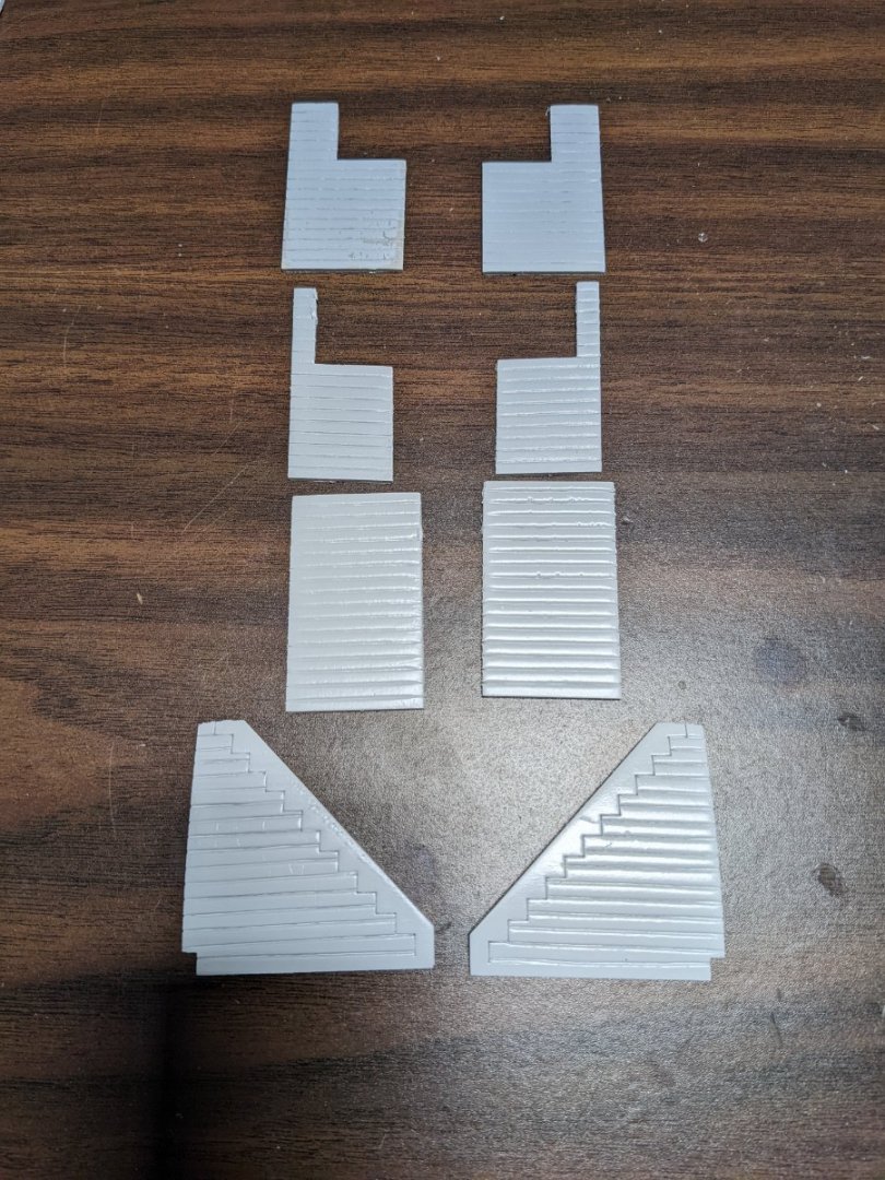
 Stairs are complete. The extra longer risers nicely closes the gap between them and the tread. At long last all the compartment components for the main floor are complete and ready for installation. Below are the walls for the aft compartment. Horizonal strips (1/8" x 1/8") were added at the top of the wall (per instructions) to provide a better gluing surface for the boiler deck. In addition I added some vertical strips to provide a little vertical support in the event I am feeling strong and attempt to press down a little too hard when gluing the boiler deck to the main deck walls :-). One additional feature I added was two partial walls at the front end of the aft compartments. The are circled in black. Instructions say to leave that open, but to me that is really a big opening. On the finished model, one looking into the model from the side could easily see the gapping wide open compartment and rough inside walls. The two walls do not completely fill the gap so it looks more like a small opening into the aft compartments. Turn the pieces over and we have the finished walls. Again the two extra partial walls are circled in black. Below are the foreword compartment walls. Still need to attach the 4 cleats to parts 37A. Other than that, I am ready to mount the walls. Speaking of the cleats, I am not sure if the author is a comedian or I just do not have the correct skills, but in regards to mounting the cleats, the instructions say "A professional modeler would likely drill and pin the cleats" IF that is the case, then I am defiantly not a professional modeler. I have some small drill bits (.3mm) but no way would I even think of drilling and pining these cleats. Below shows the one of the small cleats (on the tip of my finger) to be added to part 37A. In my case CA glue will have to do.
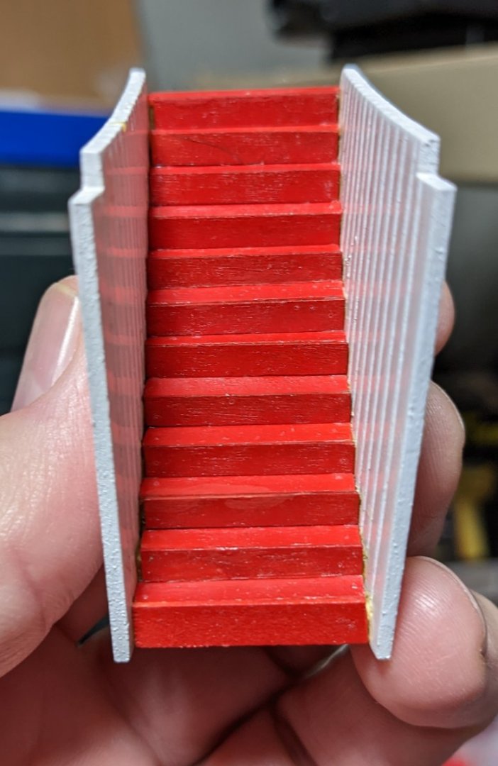
- 158 replies
-
- 4
-

-
- chaperon
- Model Shipways
- (and 1 more)
-
I agree with others..... Your planking is really good. Ship looks great so far.
- 75 replies
-
- 2
-
-
- Oseberg
- Billing Boats
- (and 1 more)
-
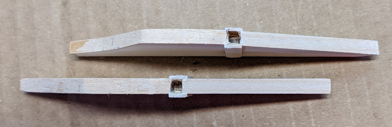
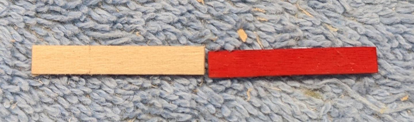
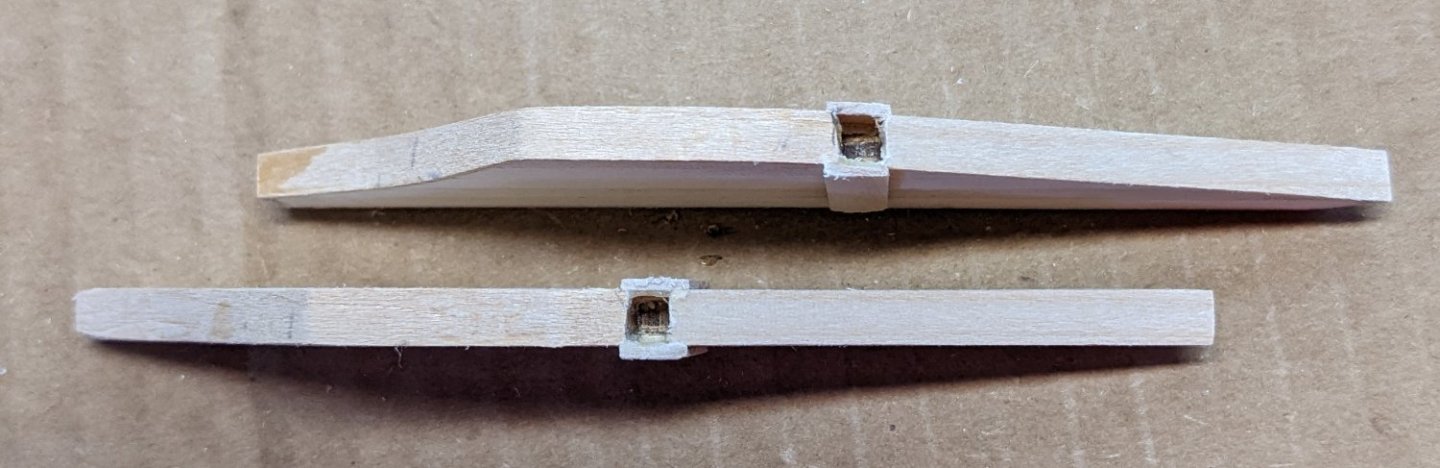
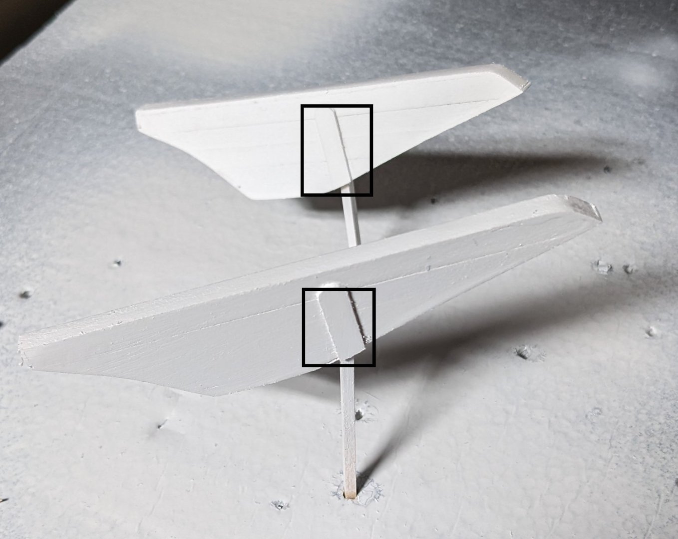
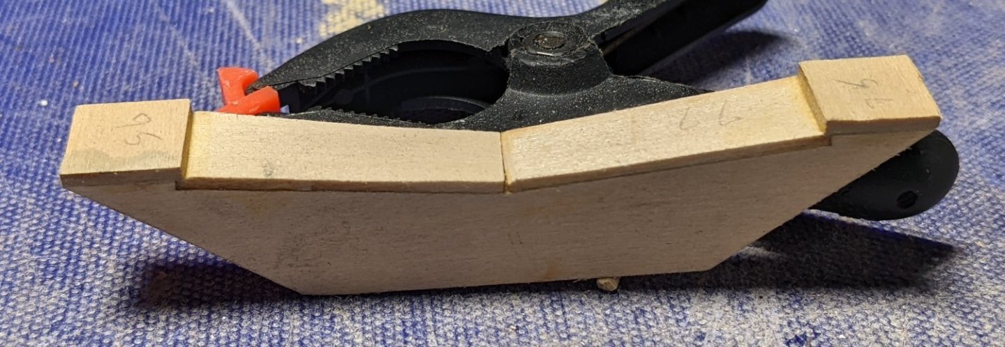
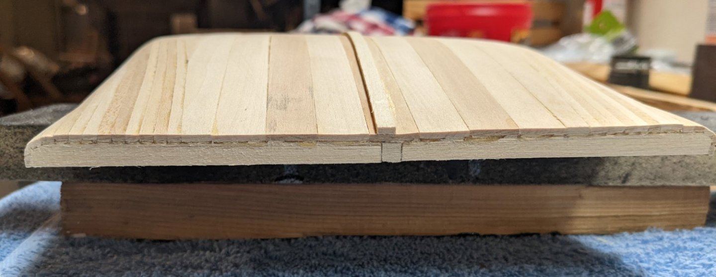
Brian, Thanks for the tip on mounting the rudders. I was planning on mounting them now as I thought they would be "more or less" out of the way. But I did not think of potential clearance issues with the paddlewheel down the line. I like your idea of holding off until I see what sort of clearance fun I have with the paddlewheel. As far as the stairs are concerned, I seem to have stumbled on a solution. It seems the risers and runners are about 1/8" by something really thin (maybe 1/64"). I had some extra 1/16" x 5/32 strips and if I remake the risers with these strips the steps seem to work out. As you can see the 1/16" x 5/32 strips are about 1/32" wider then the original risers (and a little thicker. By just replacing the risers the steps seem to fit. The extra height fills the front gap and the extra thickness fill the gap in the bap. In the below picture the top two steps seem a little short, but I have a slight outward warp in the walls at the top of the stairs. When I bring them in, all will (or should) look like the third step. We will see what happens after the new risers are painted and put into place. As long as we are talking about a little fudging,,,, there is supposed to be a 1/16" x 1/8" capstrip all around the edge of the boiler deck. Instructions talk a lot about how to bend the strips around the forward and stern corners. The two stern corners seem especially "fun" as those corners are really sharp. Purest will roll their eyes on this, but to me it makes a lot for sense to bend two 1/32" x 1/8" strips instead of one 1/16" x 1/8" strip. After soaking them, they bend ready easy and at my skill level will save me a lot of headaches. I can see me breaking a lot of 1/16" x 1/8" strips trying to make those stern bends. Below shows the strips drying around the four boiler deck sections. The two stern sections are in the foreground and the two bow sections are in the background. At this point you can easily see the two 1/32" x 1/8" strips laying back to back. But later on after the deck is planked and these strips are glued into place and sanded, the seems in between them will not be noticeable.

- 158 replies
-
- 4
-
-
- chaperon
- Model Shipways
- (and 1 more)
-
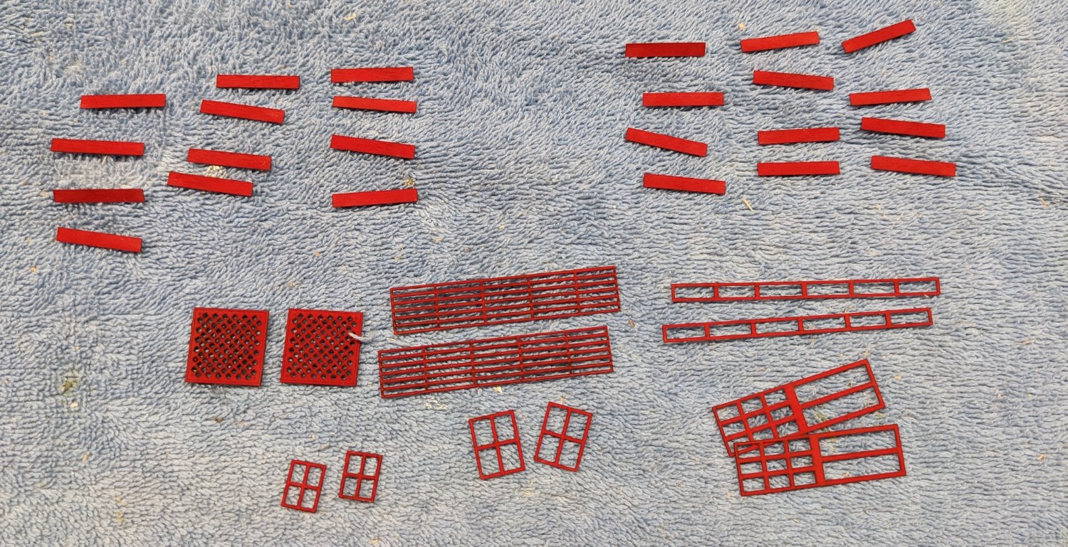
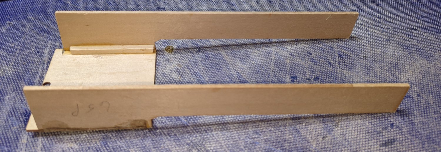
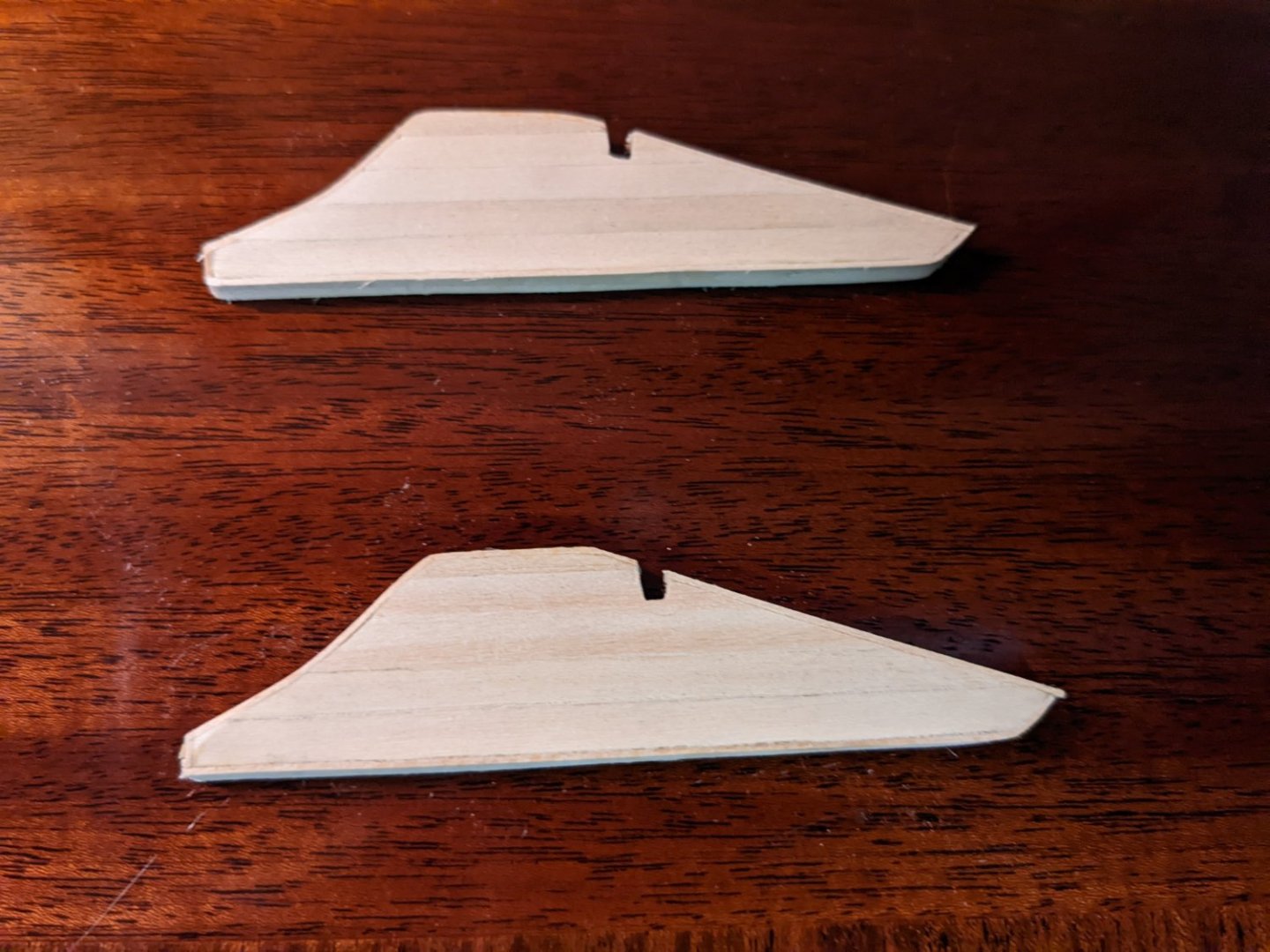
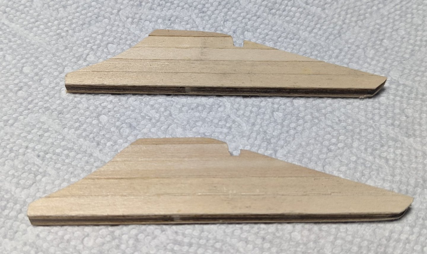
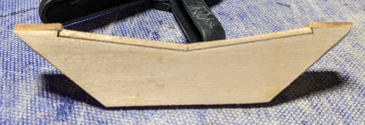
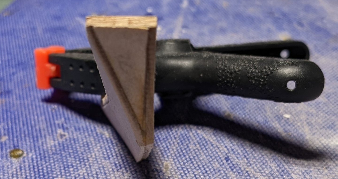
While waiting for layers of Poly to dry I started on the main floor stairs. Initially to me these looked pretty easy.... Especially if you know anything about building the circular stairs on the "King of the Mississippi". That was a real treat. Anyway I guess I am just have a thing for stairs as I seem to have made every mistake you can make (several times) with just the initial structure below, I put the two stringer fascia pieces (parts that hold the treads and risers) backwards, upside down, on the wrong side of the walls, walls upside down.... You just can not imagine how many time I had break then down and redo them. Fortunately pure alcohol is great for loosening wood glue. And as you can see below, with all the alcohol rubs and redo's the walls have become a little warped... I guess I will need to wet them again and press them back into shape. I would say be careful and get the parts correct the first time, but I think most people would think this is a pretty easy thing and just my fun with stairs. Completed the painting of the stairs steps and the main floor window, doors, and vents. Up until now I have only used rattle cans of paint, but I finally broke down and purchased and air brush. Not sure I could have painted these small part with a rattle can and not drown the parts in paint. Air brush did the job pretty nice and easy. Next level of fun will be attaching the risers and runners to the stringer fascia pieces. Naturally after dry fitting a few of them, I realized some of the stringer fascia pieces are just a smudge longer than the risers and runners. So looks like they will not just drop into place. Will take some adjustments to not show a tiny gap between some of the steps. So much for me thinking these stairs were going to be easy.. Began working on the rudders. Not sure why, but I decided to cover the rudders with planking. I thought it would make them look a little more realistic, but after you paint them, not sure that was necessary. After planking them I used some wood strips and covered the edges of the rudders... Again,,, why did I do this again? One thing I did do that to me made a little more sense was to apply some extra wood strips on the outside of the rudders where the rudder shafts roughly where the rudder shafts were located. It kind of looks like they are there for extra support for the rudder shafts. In reality they really are there to make a little box for the rudder shaft to be inserted. Without these walls there is very little surface to glue rudder shafts and a round dowel into a slit in the rudder just would not look right. This way a little glue into the box will make it much easier to glue the rudders into the rudder shafts in the hull, and kind of looks like it is supposed to be there. My opinion anyway,, And the rudder posts sticking out of the hull that will eventually accept the rudders.


- 158 replies
-
- 4
-
-
- chaperon
- Model Shipways
- (and 1 more)
-
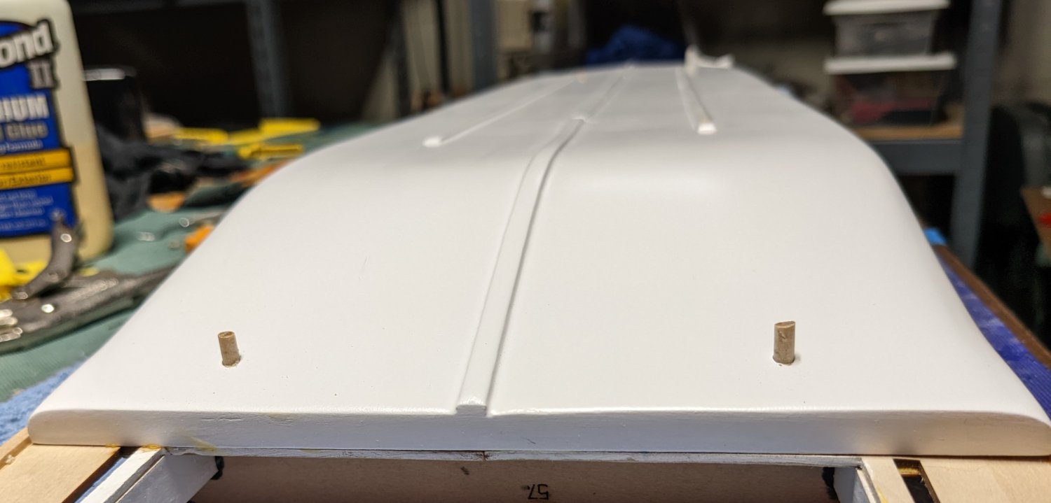
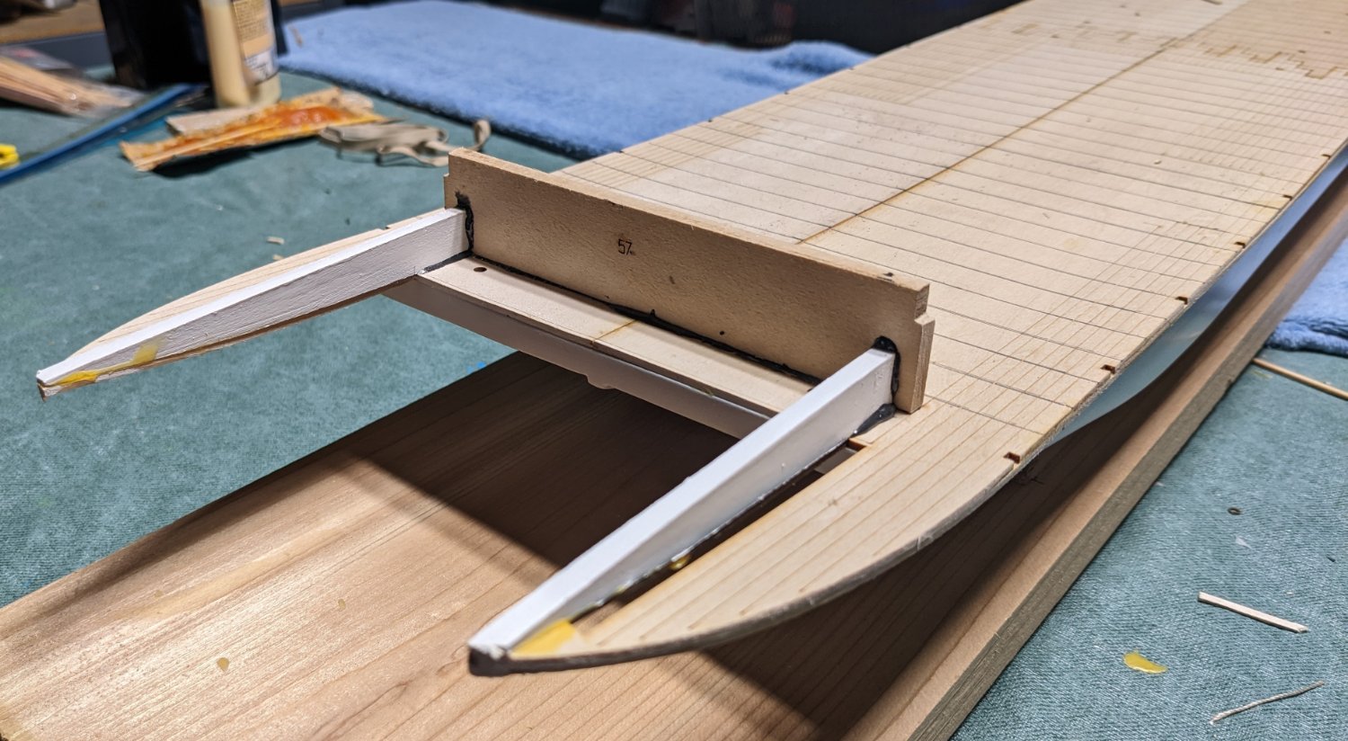
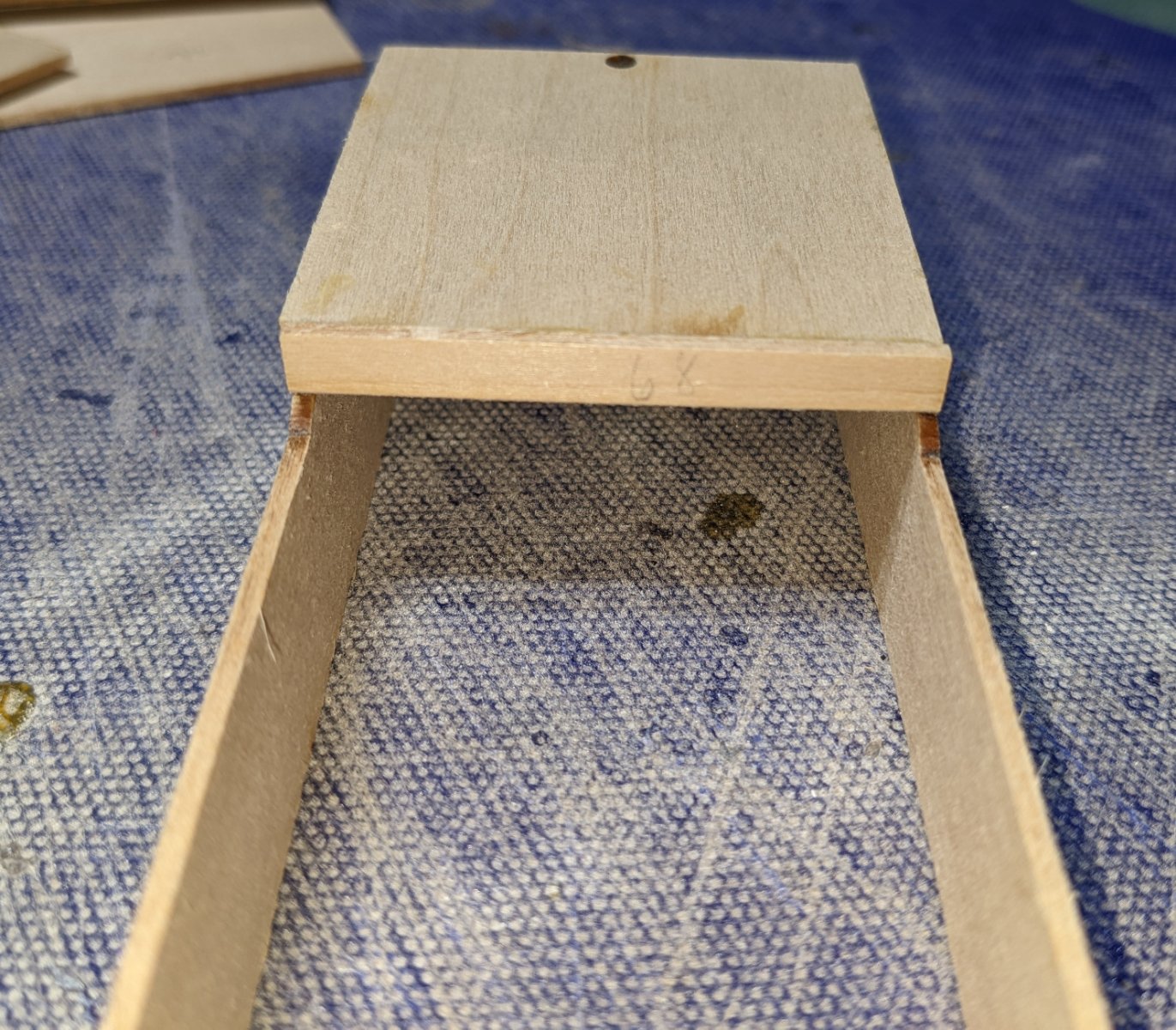
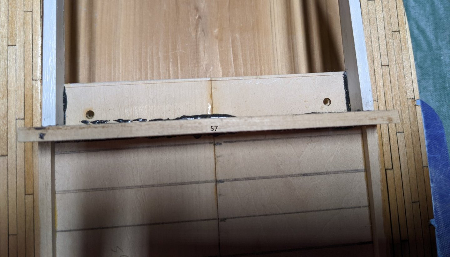
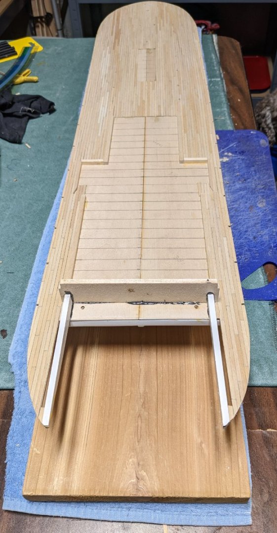
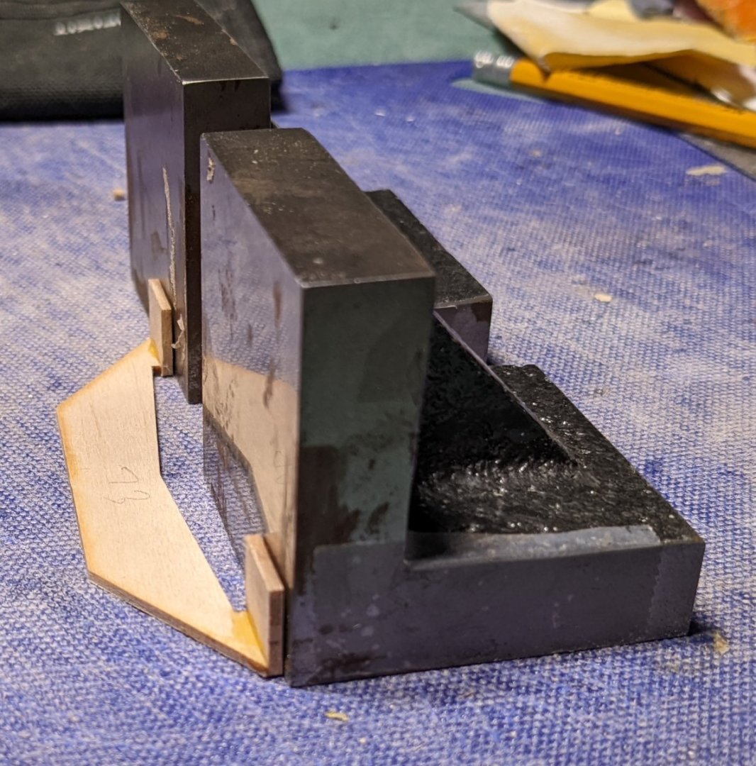
One thing I might add, but not really an issue... The instructions state to put in piece #57 right after the deck is laid. Then later on drill the holes for the rudder posts. As the picture shows below, with #57 in place, it is pretty difficult to get a small power drill into position in order to drill the perpendicular holes. Unless you plan to pin vise your way through the stern piece, attach a long drill bit to the very end of the drill. That way, even though the bit is barely in the drill, it should be long enough to drill through to the bottom. I suggest you drill the rudder posts before you epoxy in piece #57. Also, the instructions naturally state the holes need to be perpendicular to the hull and suggests using the supplied right angle template to help keep the drill plumb. Problem is, the hull is not vertical at this point. It is tilting upwards at the stern. So you can pretty much skip the supplied right angle template to help keep the drill plumb.
- 158 replies
-
- 3
-
-
- chaperon
- Model Shipways
- (and 1 more)
-
And after a coat of Puritan Pine stain..... Next up will be a couple coats of Polyurethane

- 158 replies
-
- 7
-
-
- chaperon
- Model Shipways
- (and 1 more)
-
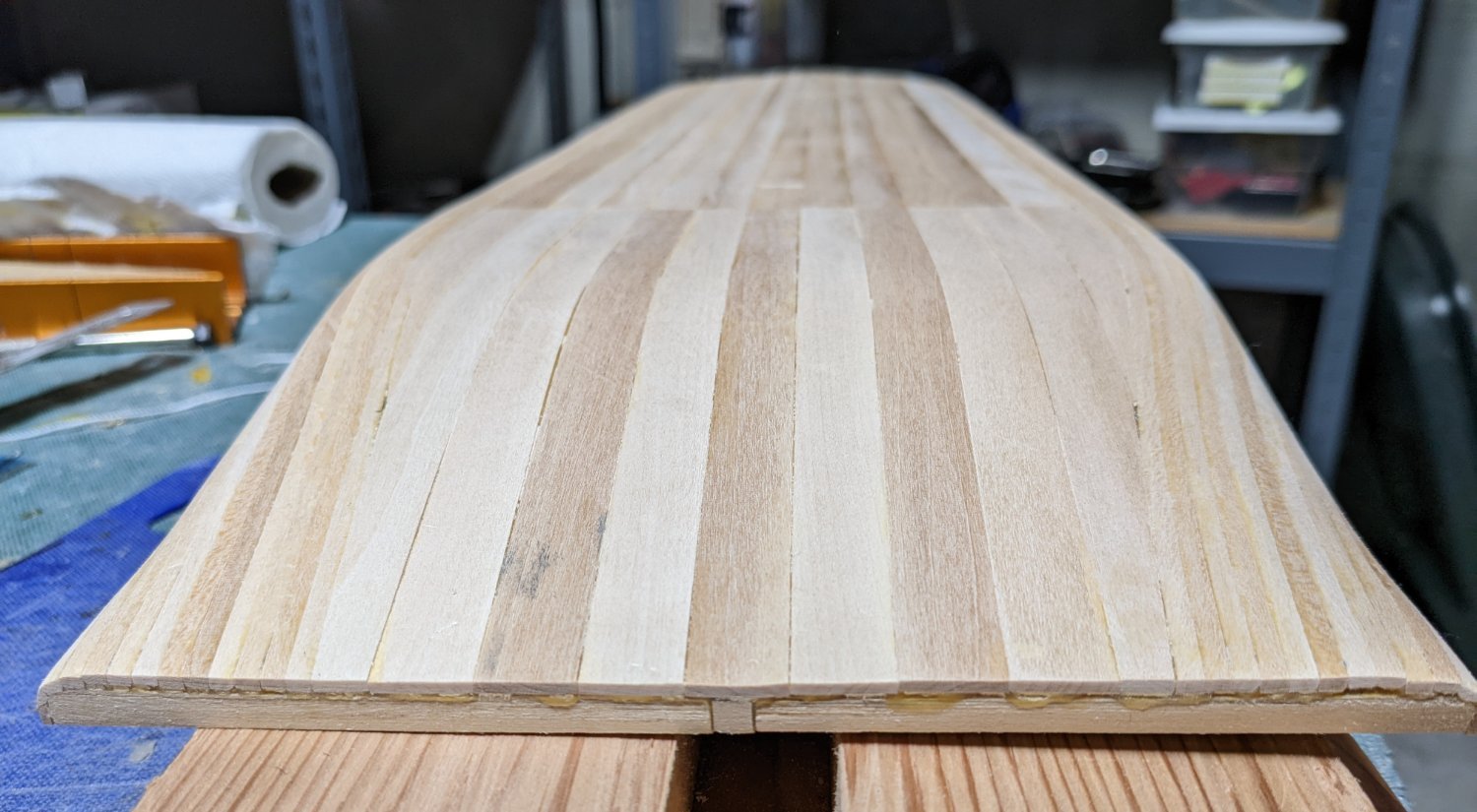
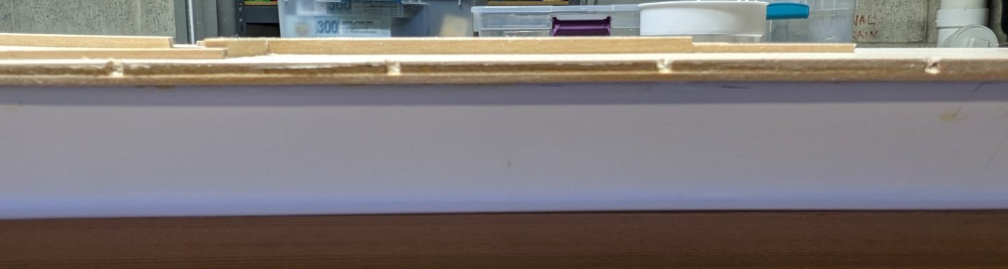
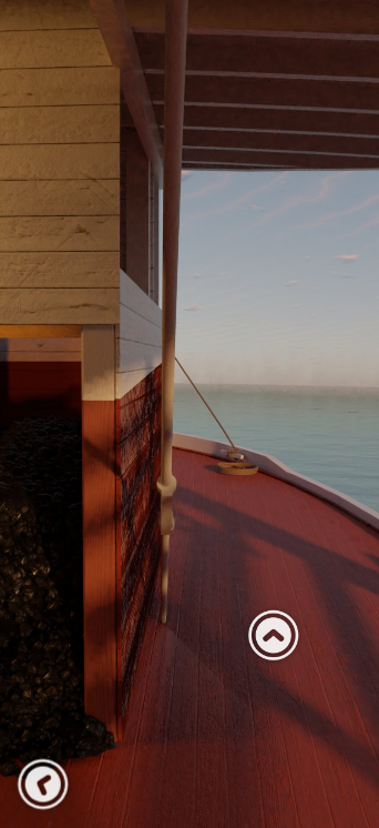
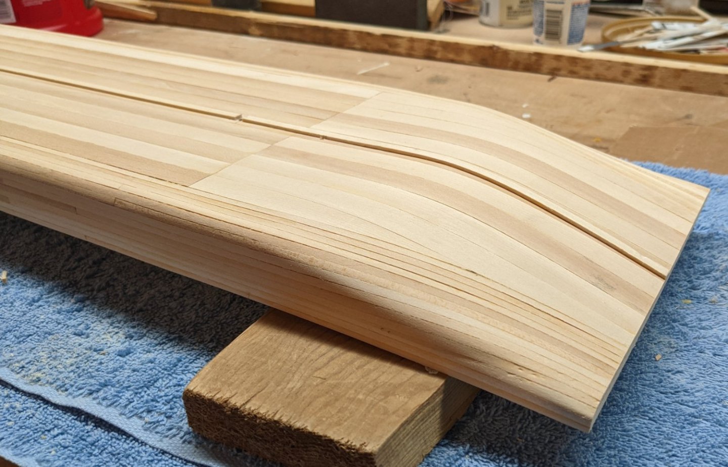
Juhu, I did not make an attempt to match up the planking with the actual Chaperon. I just like the 1,3,5,2,4 pattern with planking so I went that. Since you are interested in being a authentic as possible, take a look at the 3D viewing of the Chaperon. It was sent to my by mbp521 (brian) and gives a real good look at the Chaperon.. 3D virtual walkthrough of the Chaperon https://www.jensmittelbach.de/steamboats/chaperon/index.html Brian, Thanks for the reminder on the fantail extensions. Since I epoxied them, I kind of forget about them.... But epoxy or not, I agree they need to be treated with care, or there will be some tears. Planking trim and sanding have been completed. Plan to stain and add a couple coats of poly. Again,,,,, the real Chaperon had painted decks,,,,, but like the planking pattern, I just like the looks of a natural planked deck 🙂 Not sure if this will end up being good or bad, but note the below closeup of the decking. Earlier in the log I mentioned the fact that I was concerned about later gluing the 1/16" x 1/4" rub rail to side of the 1/16" deck. As such I added a 1/8" strip under it to provide a better gluing surface. After the deck was planked (1/32" strips) you have to cut out the notches for the later stationaries. Below you see the notches cut out, but instead of cutting the notch through all three layers of wood, I just cut out the notch into the planking and the actual deck. The notch does not go all the way through the added 1/8" strip. You can go through the strip if you like (and probably would have been easier), but this way I figured I would have solid base for the stationary. Again, this is probably is the category of way overkill, but that is how my mind works,,,,, "Why do something easy when you can make it hard".
- 158 replies
-
- 3
-
-
- chaperon
- Model Shipways
- (and 1 more)
-
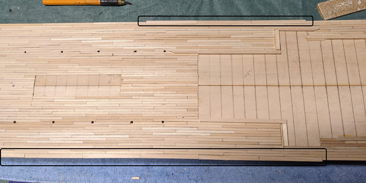
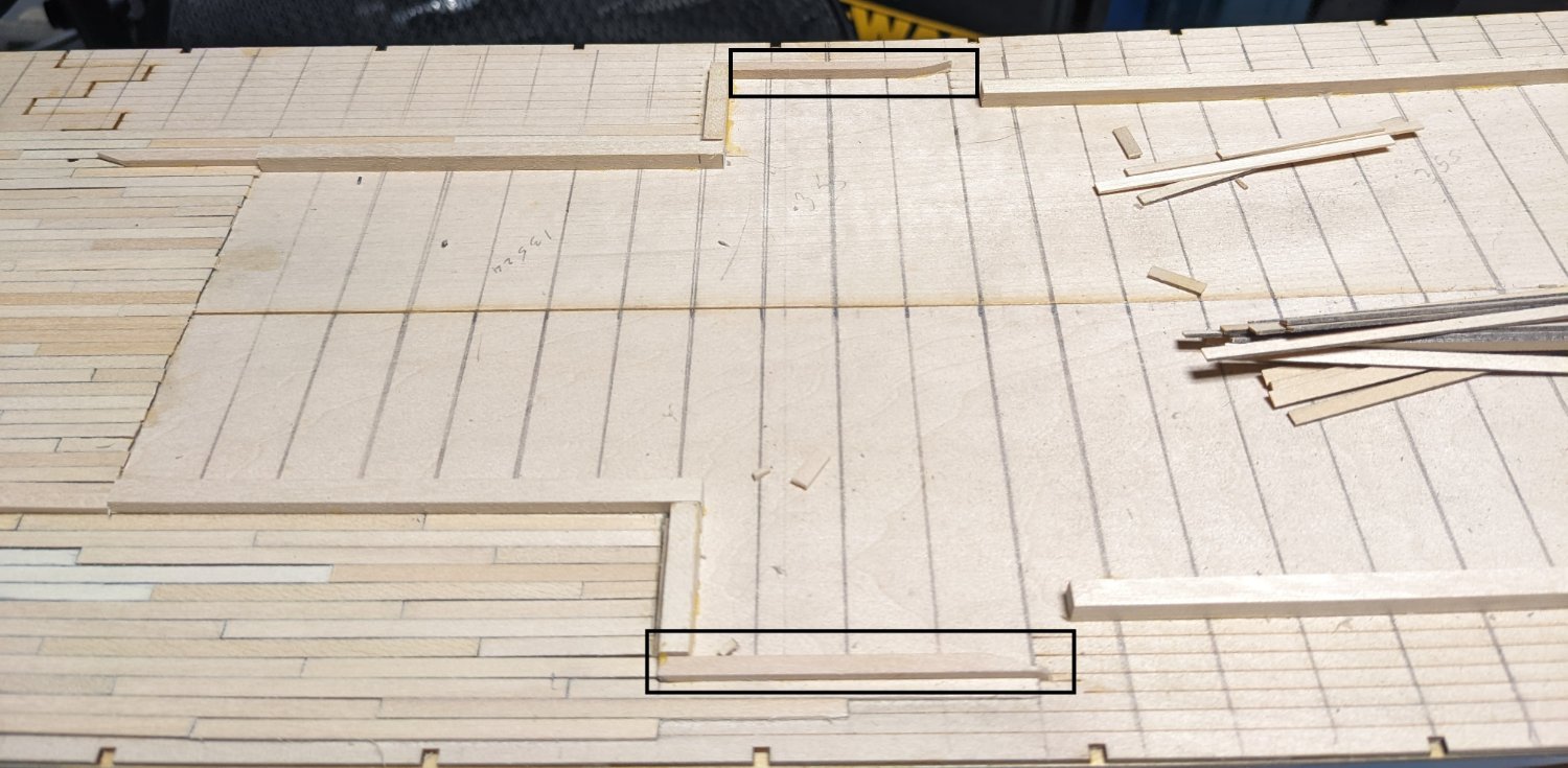
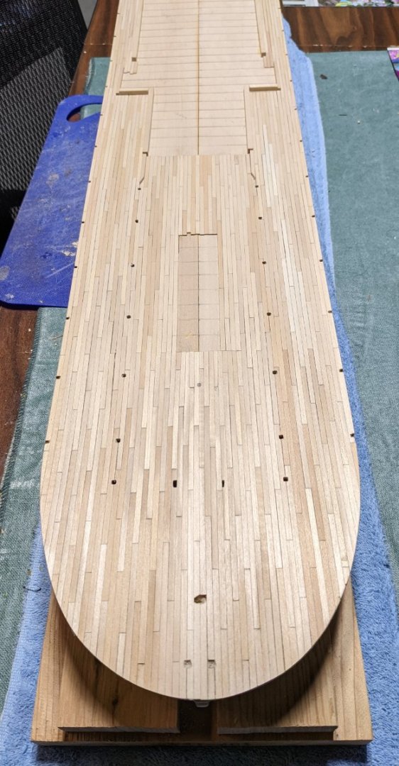
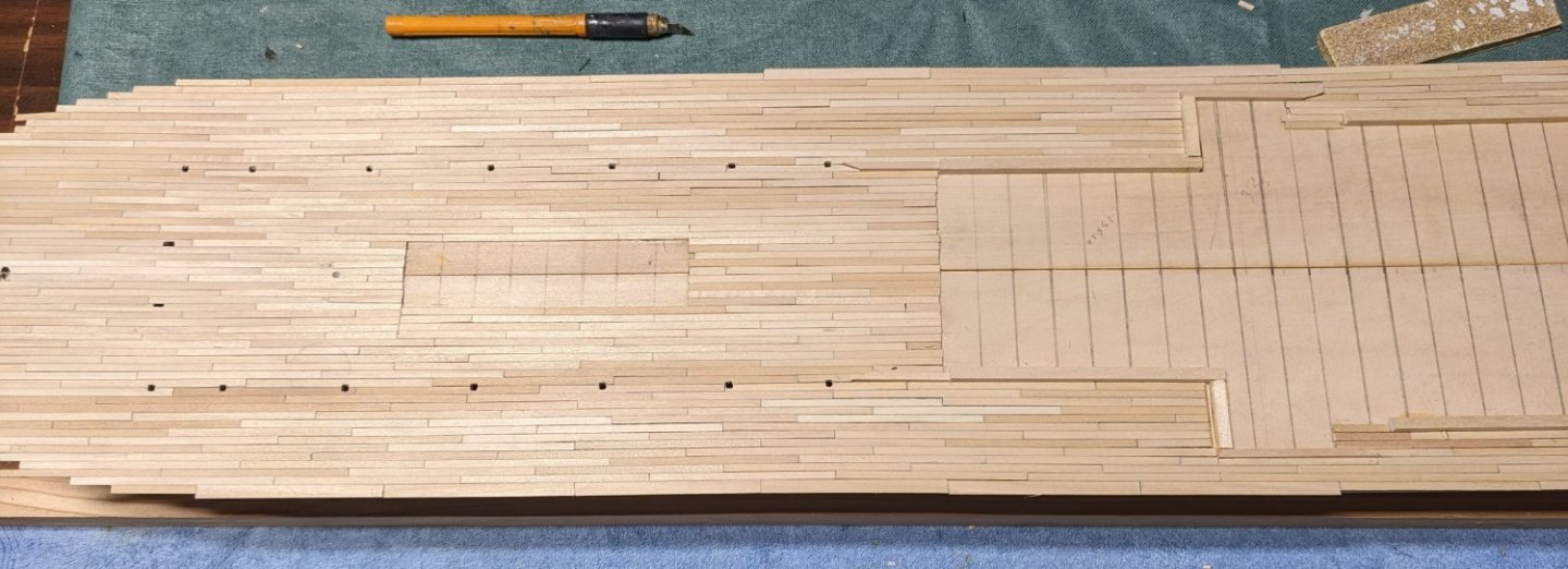
Cathead and Brian, Thanks for your comments and suggestions. I really appreciate them. As for the variation color, I think after a sanding, stain, and poly, they will look OK,,, No so worried about it any more. I really like the idea of blacking the entire 24" strip and then only have to blacken the ends. As of today (pictures below) I have completed the main deck planking, but I will try that approach on the next boiler deck. Still have to trim around the edges, but the planking of the main deck as completed. As mentioned earlier, the area's not planked are much smaller than what is called for in order to hide the none planked area if one is looking on from the side. I do like the Brian's idea of painting that area black instead of all the extra planking,,,,, but then again "dumb you get early, smart you get late". I will consider that suggestion when planking the next deck. Despite my best efforts by the time the planking got to the edges the lines were not completely straight. There was about a 1/32" difference on a small section of the starboard side (top) and a little longer section on the port (bottom) side. Rather than try and squeeze in some 1/32" square planks I decided it would be much easier to put in a 3/32" plank and then trim off the excess. On the port (bottom) side the picture got a bit skewed. In the picture that edge looks pretty curvy. It really is pretty straight. Tomorrow is trimming and sanding day... and perhaps stain too if all looks good.


- 158 replies
-
- 6
-
-
- chaperon
- Model Shipways
- (and 1 more)
-
Jason, The Oseberg has been on my with list for some time now. Someday I would like to take it on. It may be awhile though as my current project is the Chaperon (Steamship) and that will take me awhile. However I am anxious to view your build. Hope you have fun with it john
- 75 replies
-
- 2
-
-
- Oseberg
- Billing Boats
- (and 1 more)
-
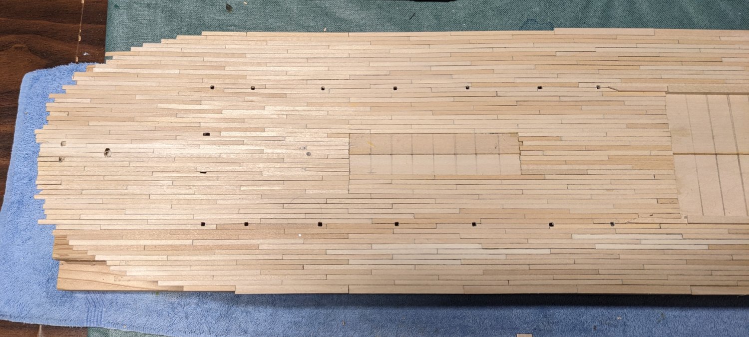
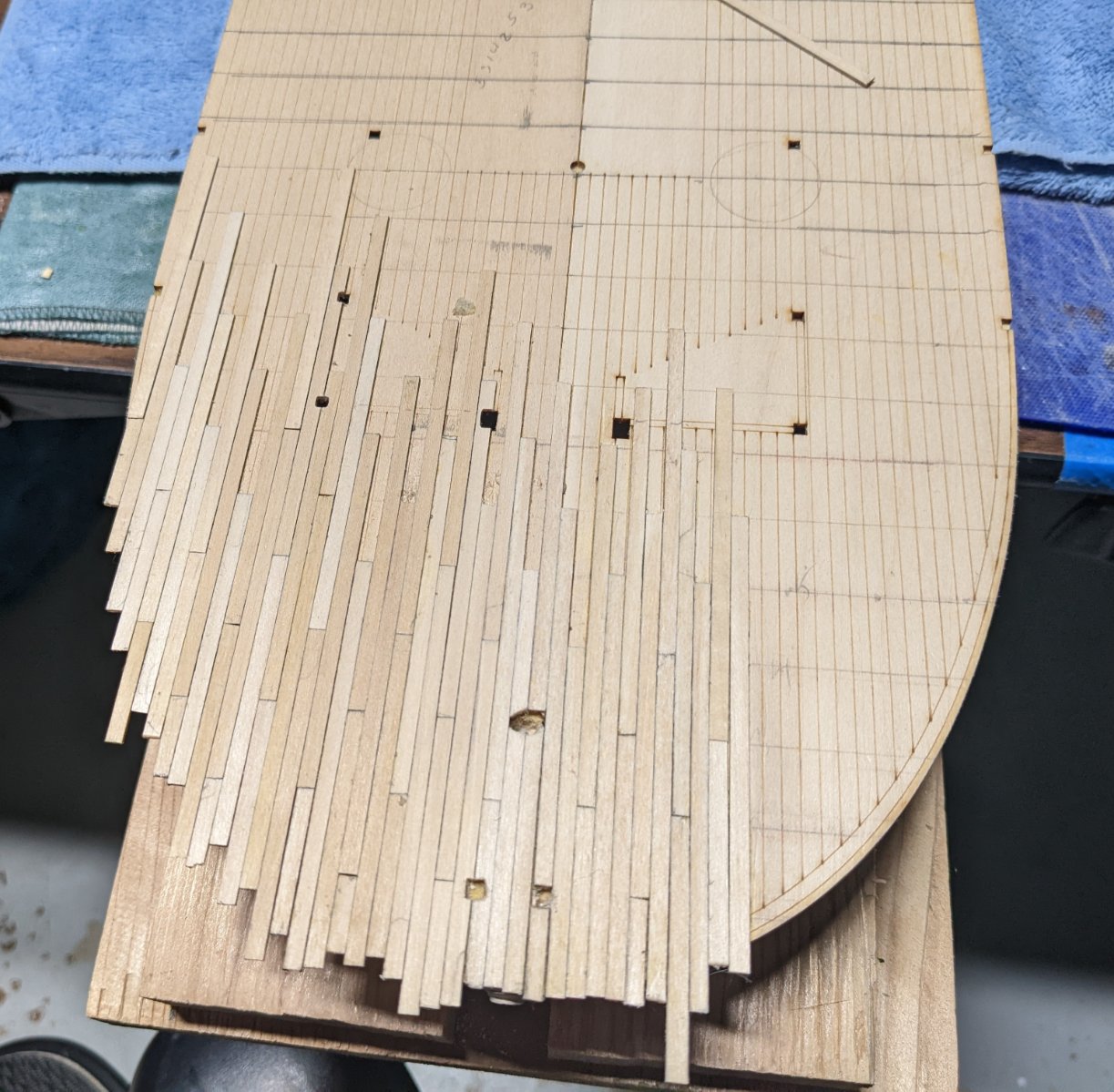
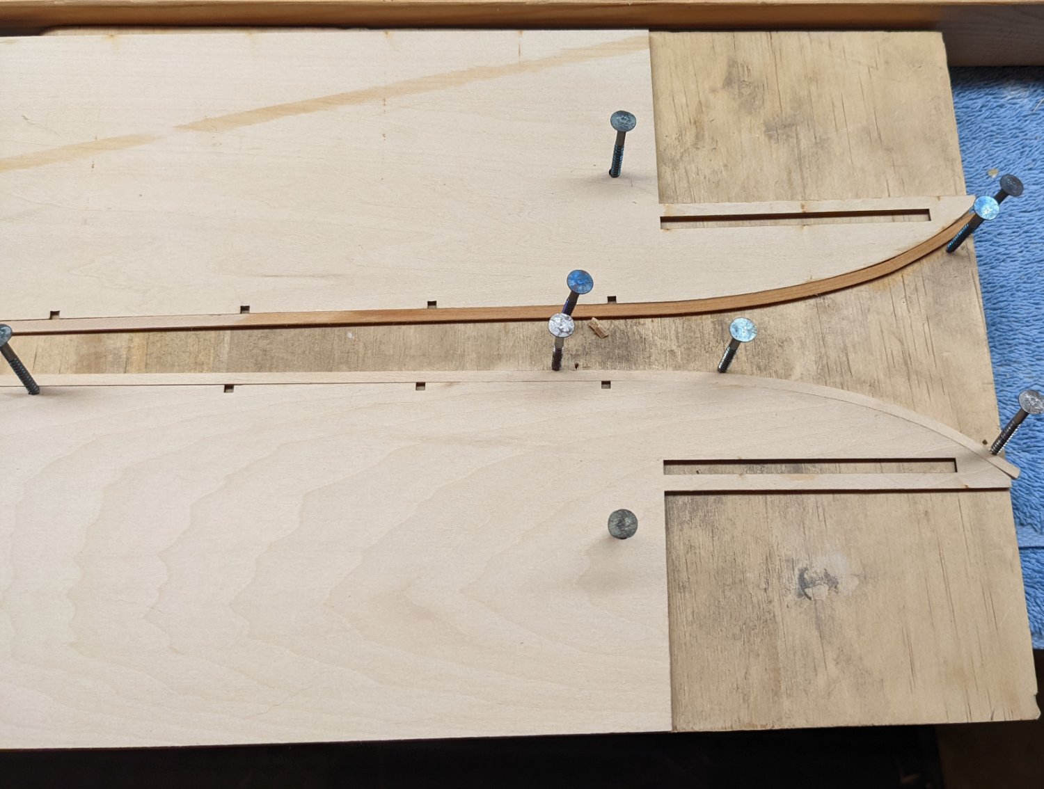
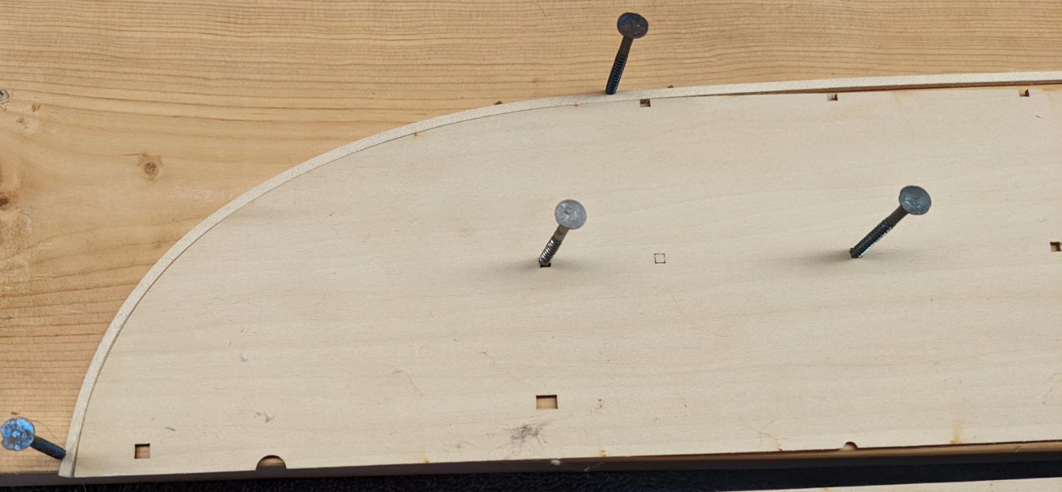
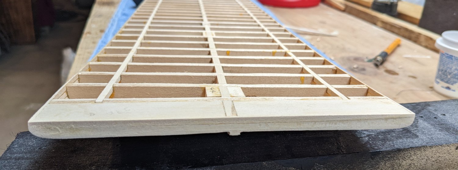
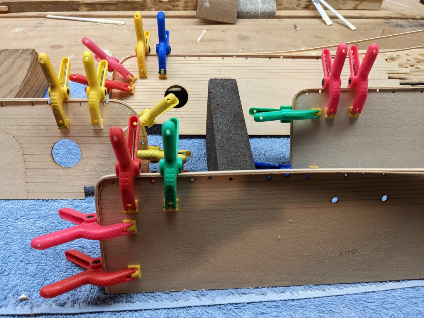
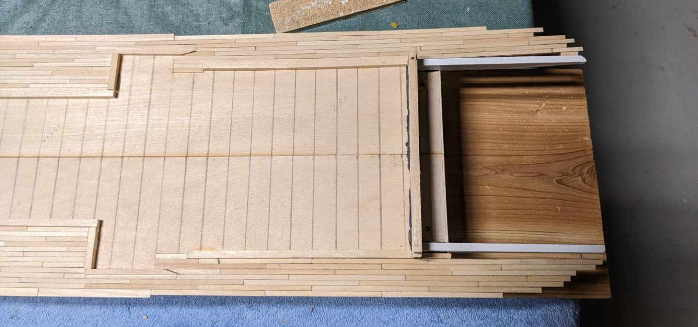
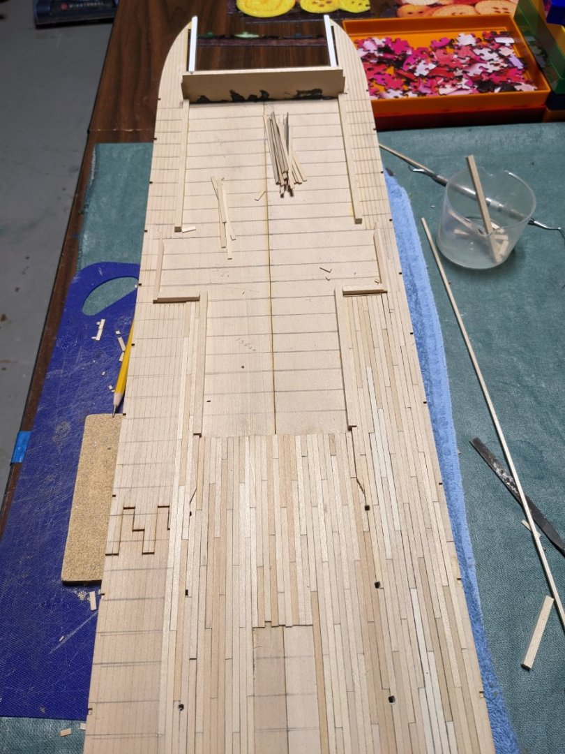
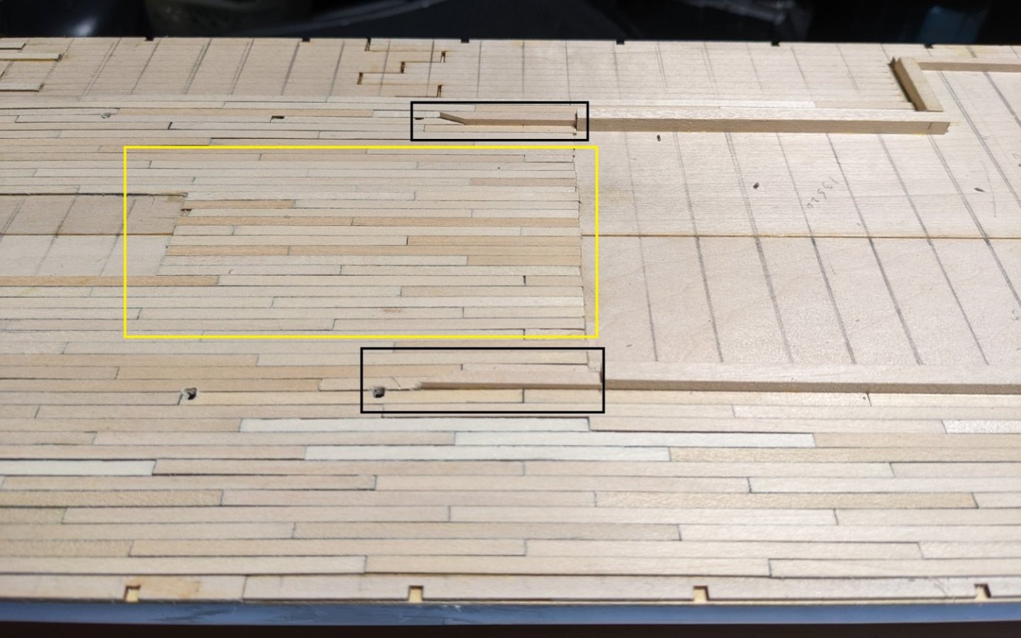
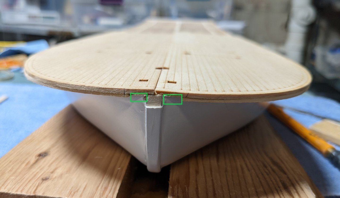
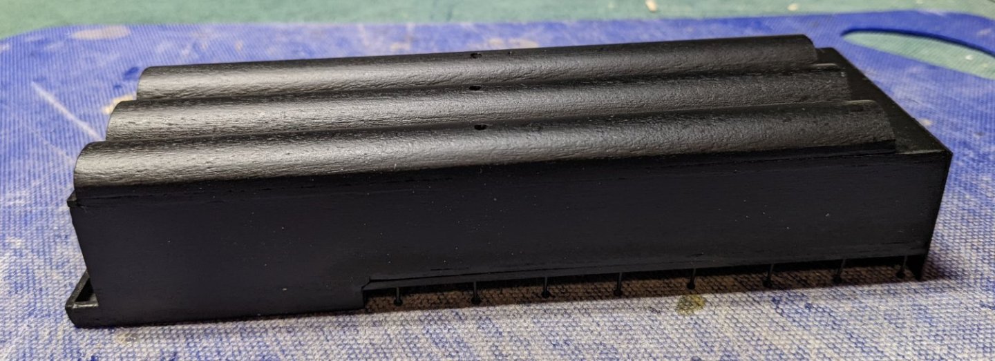
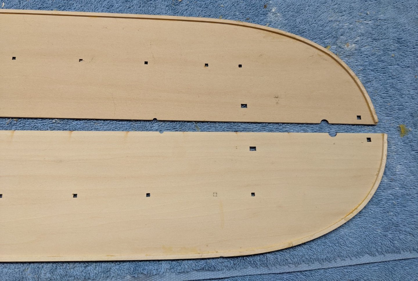
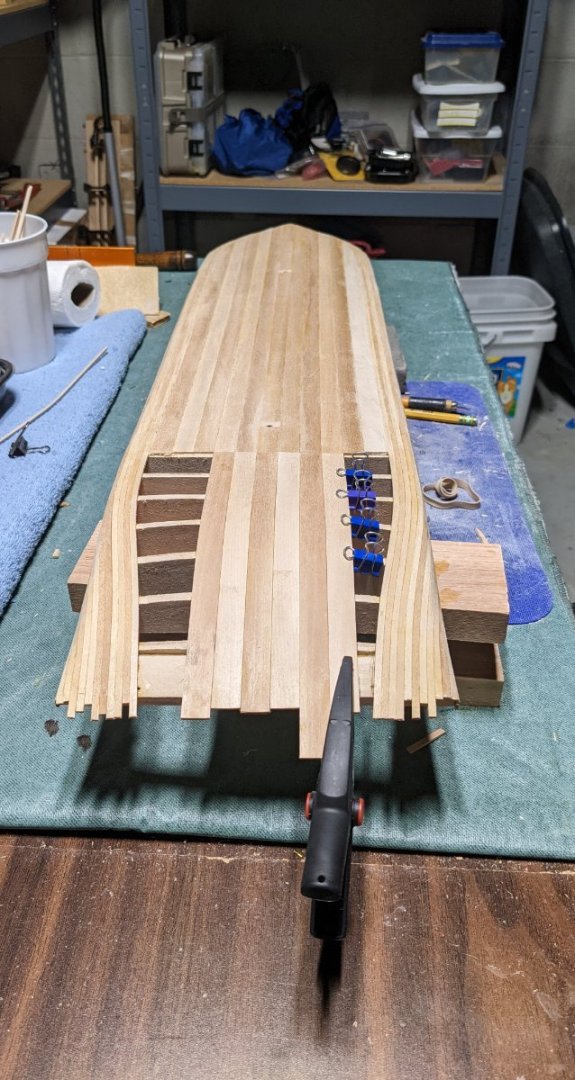
Planking ongoing,,,,, I really really wish I decided to use 20' (5") planks instead of 12" (3"). I am getting real tired of cutting, blackening, and gluing each of the 3" planks. Even though the 1/8" etched lines are very helpful with keeping the planking straight, with variations in the wood planks, it is very easy to stray with the planking and get our of line. Ask me how I know this 🙂 It is a rather large model with long decking. Play close attention to you plank lines. The black dot (marked in green) is where the little dowel attached to the bottom of the boiler ash catcher is supposed to be inserted. I assume this is to insure the boiler is located in the correct sport for the smoke stacks to fit into the holes in the boiler deck. Somehow I am imaging alignment issues when I add on the boiler deck, so I did not attach the little dowel to the ash catcher. I marked it with a pencil for general reference, but I wanted to have a little "play" as to where the boiler is located. To me, pinning down the boiler to one exact spot, with all the other variables in ship building, somehow to is asking for alignment issues. We will see if I regret this decision later on. The area in red is space under the boiler and can not bee seen. So no sense planking it. However that space is much smaller than the actual size designate by the etched lines on the deck. Test fitting the boiler with the supplied etched lines I realized if I only planked to the etched lines, when looking at the model you would see the missing planking under the boiler. This way when the boiler is in place, it will looked like the planks go all the way under the boiler. It is also painfully obvious the variations of color on the planking strips. Hopefully when I get to staining it they will more blend together... We'll see, but not much I can do about it. Instead of 1/8"x1/8" boards all around the aft cabin area, I choose to use 3/32"x3/32" boards. Probably way overkill as 1/8"x1/8" boards would probably supply ample gluing surface, but I just wanted a little extra gluing help. I just know it will be lots of fun trying to square up the walls at the corners. Hopefully the little extra gluing surface will help. The boards in black below are the normal 1/8"x1/8" boards and they do not go all the way to the designated end. Here again I did not want someone looking into that area and see the boards. Stopping short still provides plenty of gluing area at the end of the wall. The wall itself will go all the way to the designated end spot. Same issue with the main opening amidships. The boards in black are 1/8"x1/8" and they do not go all the way to the designated end. Again just to avoid them showing when looking at the finished model. Similar to the amidships section in yellow. Same over planking the designated area to avoid showing areas not planked. Not sure I had to do all the over planking, but easy do do now and do not want to risk wishing I had done it later on.


- 158 replies
-
- 2
-
-
- chaperon
- Model Shipways
- (and 1 more)
-
As you say the original Chaperon had painted red decks, but I too plan to have just stain and poly my decks. After all the work, I have a hard time covering them up with paint. As for 20' decks, I really wish I had done that. Cutting, marking the edges, and gluing these 3" planks is driving me crazy. A 20' (5") plank would have been so much easier... And I guess more authentic too. I am about 1/2 way down the hull. I will post some pictures later today.
- 158 replies
-
- 2
-
-
- chaperon
- Model Shipways
- (and 1 more)
-
I have ordered several of my cases from Grandpa's Cabinets ( https://www.grandpascabinets.com/ ). Bring you wallet,,, he is not giving them away by any means. But to me the quality is fantastic.
-
Brian, Thanks for your comments.... As I mentioned earlier, and as you have said, it is (and will be) a very long process. I am about 1/5 of the way down the main deck. We had guest over for the Labor Day weekend so shipbuilding came to a grinding halt. For those of you who plan to plank the deck, I really recommend using 1/8"x1/32" planking. 1/32" thick plans will not throw off an measurements that might effect the model later on, and the 1/8" width "more or less" matches up with the 1/8" etching on the planks. Various wood thickness and such you will not be able to stay in the 1/8" etching lines, but they are a good guide to at least help you keep the planking straight. In my case I tried to simulate a 12' plank, so my planks were 3" in length. Planking a 34" main deck (and eventually the boiler deck) 3"x1/8" is a lesson in patience. I am going "nuts" staring at planking and trying to keep the 1,3,5,2,4 patter straight. I do not know if the Chaperon used 20' planks, but if they did, in the name of being more accurate (and not going crazy with planking), by all means use the simulated 20' planks which would come to 5" on the model. You can thank me later.
- 158 replies
-
- 2
-
-
- chaperon
- Model Shipways
- (and 1 more)
-
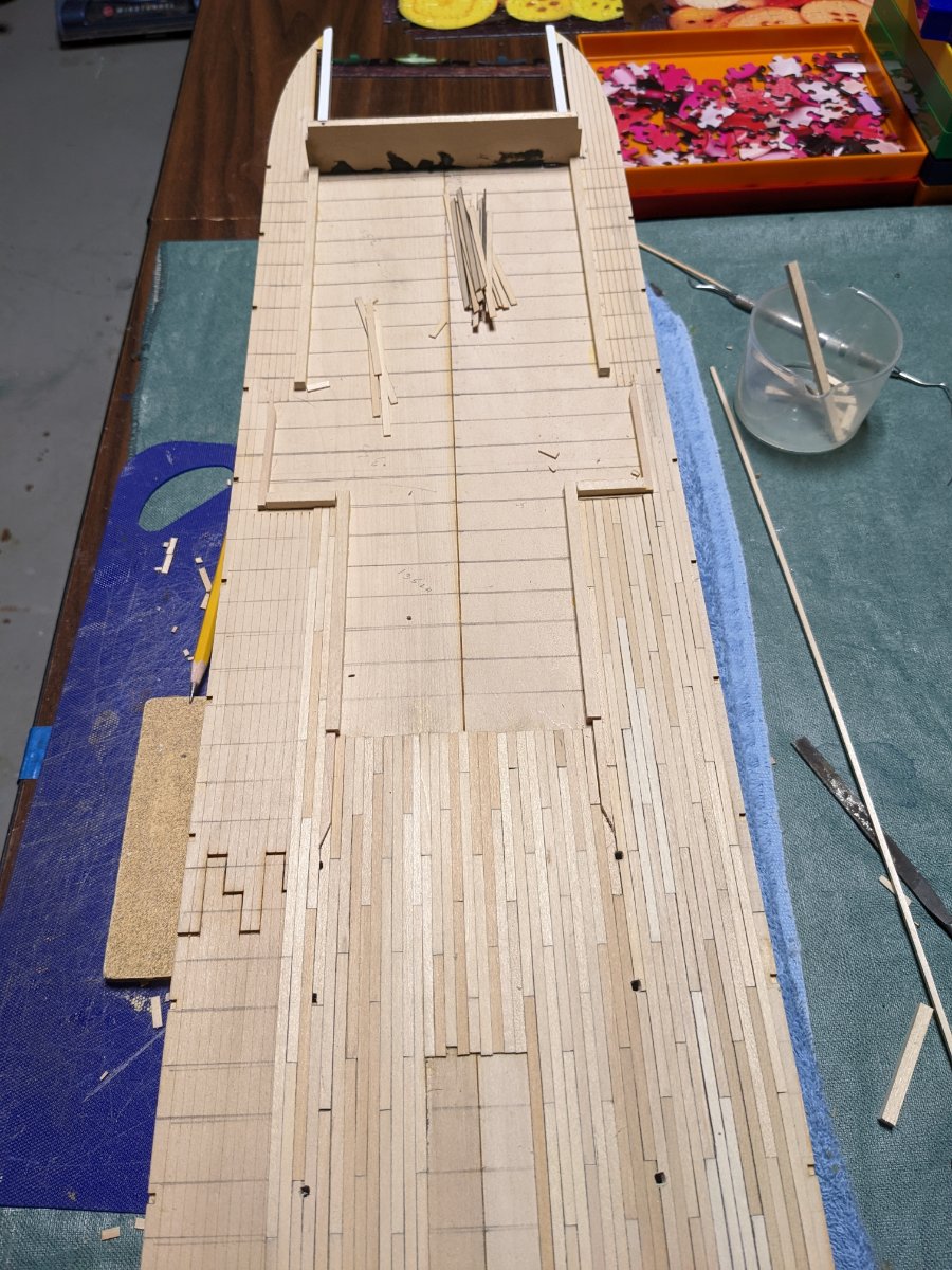
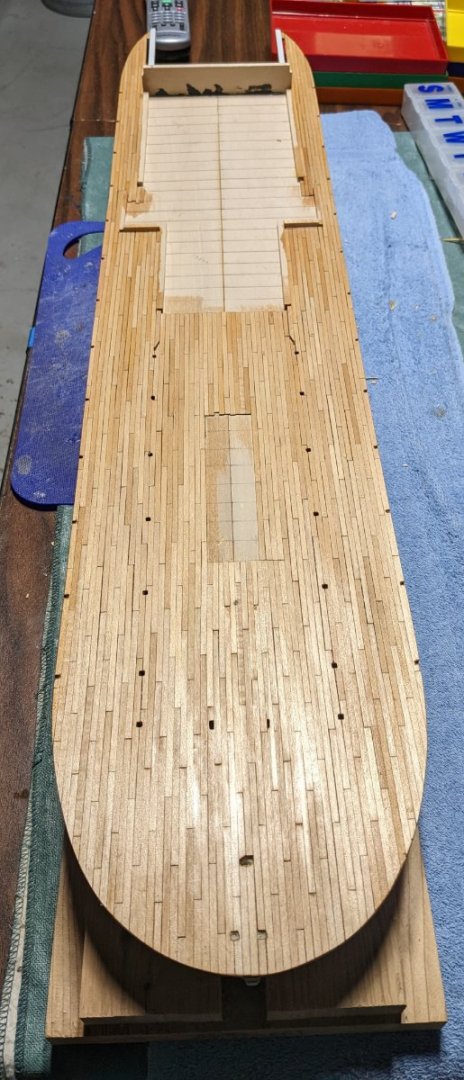
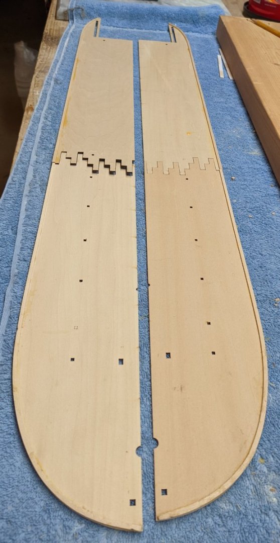
Per instructions I epoxied part 57 to the deck and parts 51 A/B to 57. If you are not careful and get to think you know what you are doing, it is very easy to epoxy parts 51 A/B upside down (with the curved side up). Ask me how I know that 🙂 Mistake has been corrected and 51 A/B are correctly epoxied with the curved side down. After the epoxy set up the aft end of the deck was bent upward and glued to parts 51 P/S. Still need to clean up some of the glue and touch up the paint. The black epoxy will not be seen once the walls are up. As mentioned earlier, I planned to plank the main deck and the boiler deck. Below show the beginning of the very long process of planking the main deck. Even though I do not plan to plank the parts of the deck that are not shown, it will still be a very long process. Each plank simulates a 12' plank and is 1/8"x3". For the caulk lines I used the usual #2 pencil on each plank. On a 34" boat I am going to be at this for awhile. I am using a 1,3,5,2,4 pattern and plan to carve out each hole in the deck as I go along. To my simple mind, the hardest part of this 1,3,5,2,4 pattern is the bow section. As the bow curves away, I have a really hard time keeping track of the pattern. However, once the bow section is complete, the straight run down the hull should be much easier. Famous last words 🙂


- 158 replies
-
- 3
-
-
- chaperon
- Model Shipways
- (and 1 more)
-
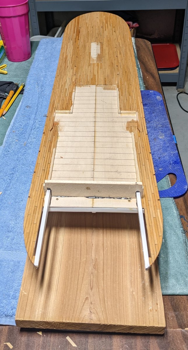
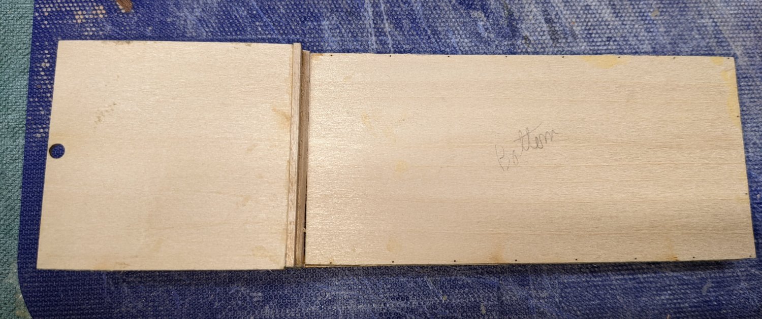
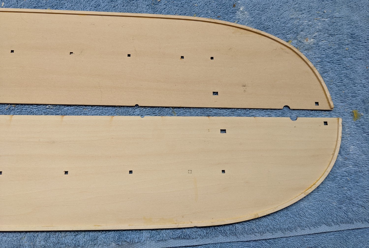
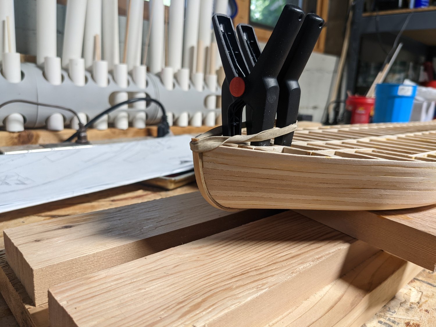
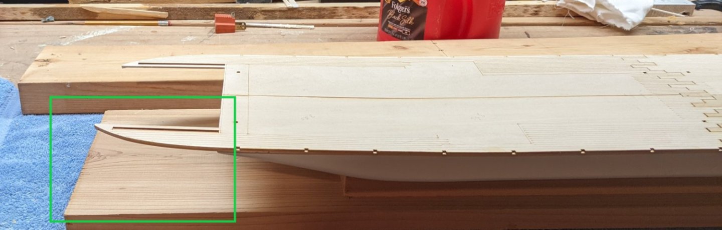
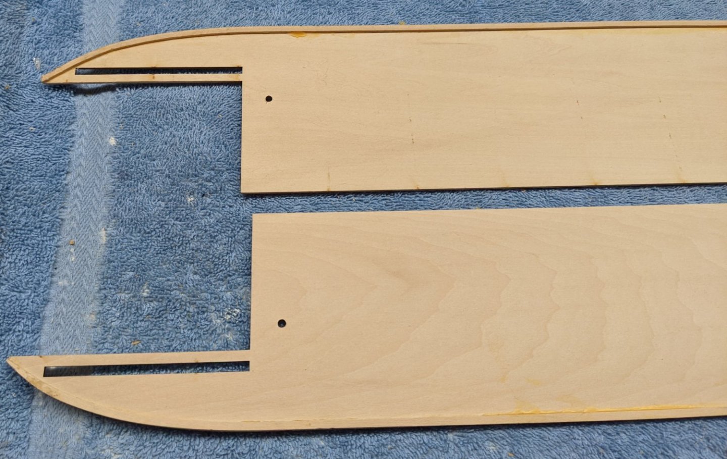
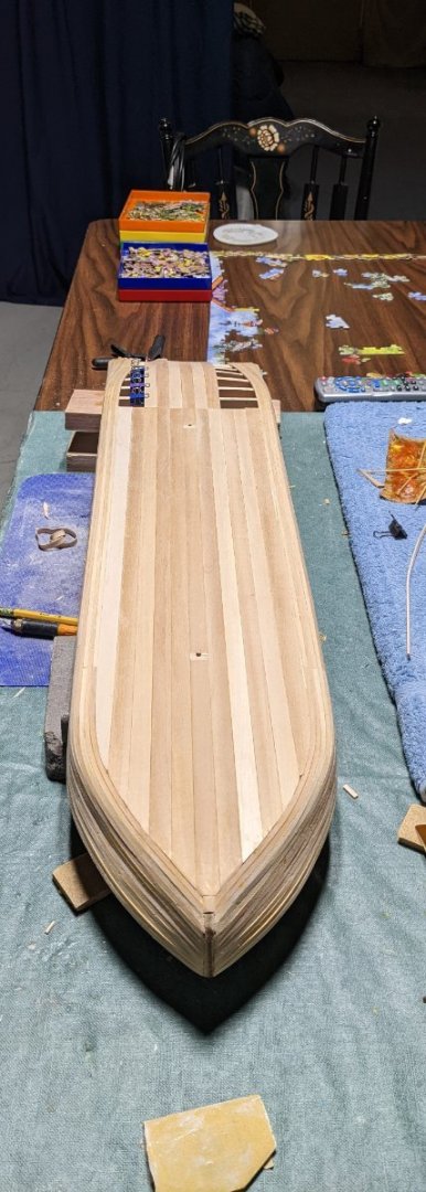
Yard Sale stuff removed, Starboard side glued down, and Yard Sale stuff piled on the Starboard side. Once dry and removed, ready for planking. Just gotta love those nasty seams in the middle. Actually, the seams in the middle not not much better. I had always planned to plank the deck, so not a big deal. I plan to plank with "1/32"x"1/8" strips. The trick will be to keep track of all those holes and transcribe them onto the planking. One thing I forgot to mention earlier when I was talking about the temporary stand the hull is attached to while building. Note in green below, the stand extends a few extra inches to "somewhat" protect those skinny extensions off the back of the hull against something sliding up against them or moving the boat and accidentally sliding it into something. Not fool proof, but hopefully will prevent some tears.
- 158 replies
-
- 5
-
-
- chaperon
- Model Shipways
- (and 1 more)
-
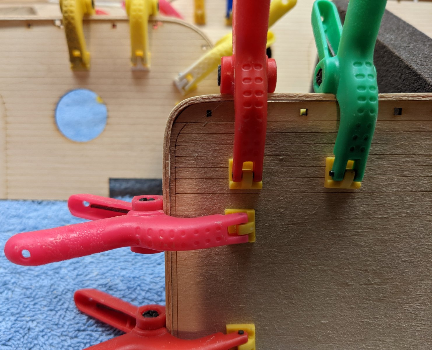
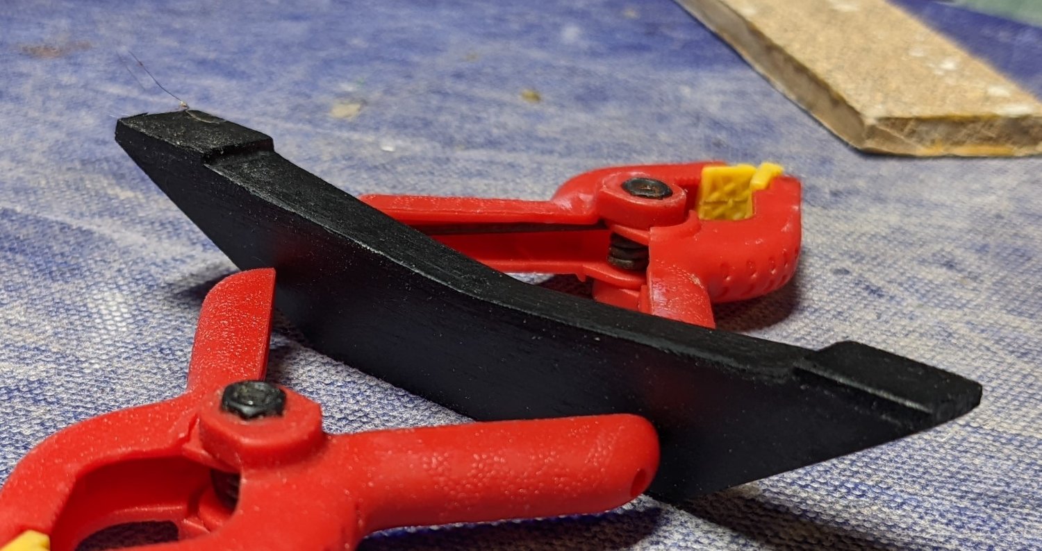
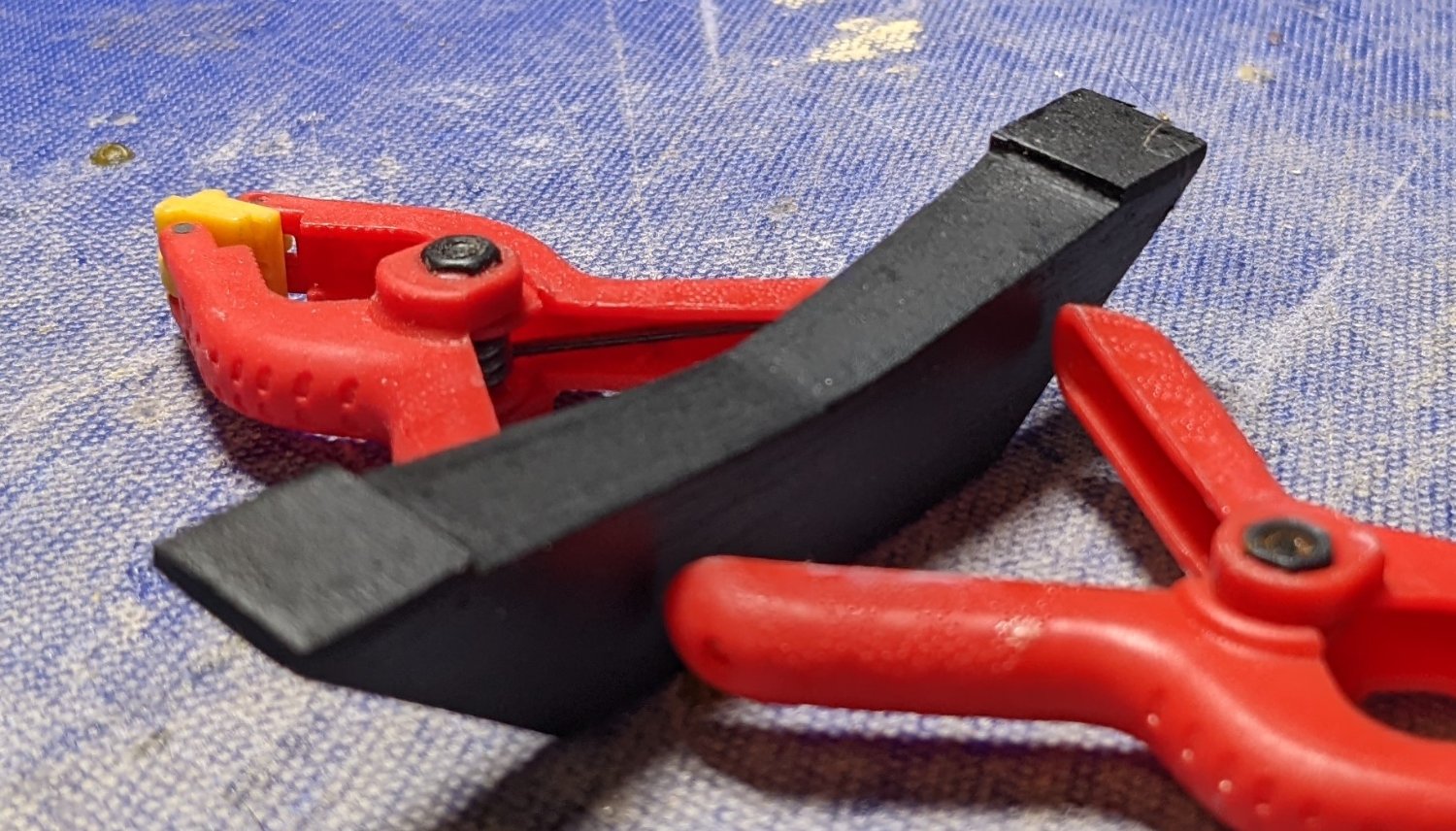
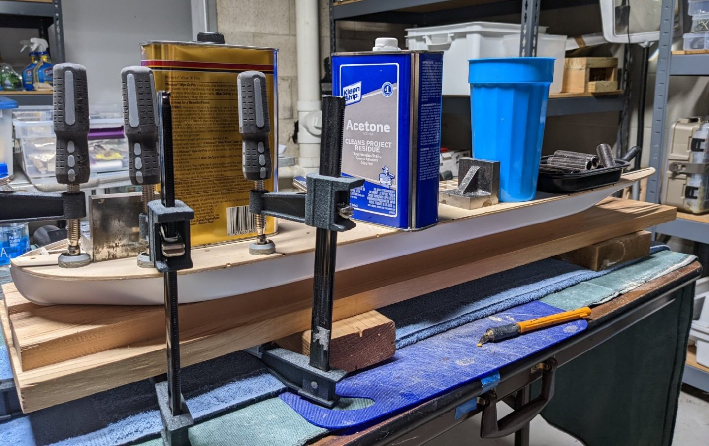
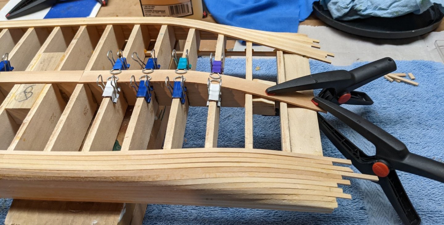
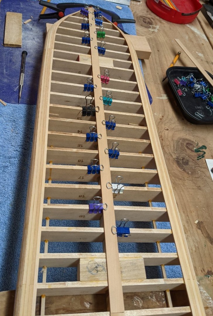
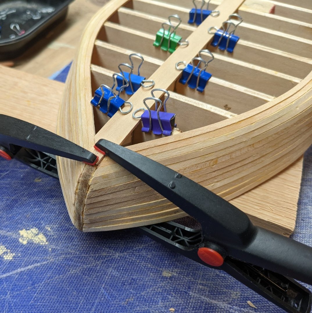
Marcus, Brian is correct. I got them at Micromark. You need to get these clamps.... They are great when a plank needs a little extra (shall we say) "persuasion", or in a tight spot where a normal clamp will not fit.
- 158 replies
-
- 2
-
-
- chaperon
- Model Shipways
- (and 1 more)
-
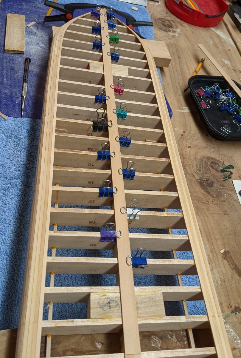
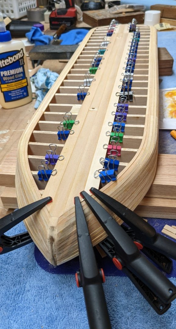
With hull as good as I can make it, time to mount it on it's temporary base. To me having a steady base for building is a must. This way I can push and tug on stuff as the build progresses and not have to worry about the ship moving on me. Before putting on the decking, this is a really good time to trim off 3/16" from the top of the keel to make room for the eventual 1/16" x 1/4" strips that form the rub rail and go all the way around the deck. Note trimming off only 3/16"allows for the 1/16" x 1/4" trim strip that also cover the 1/16" decking. Below decking is just laid on the hull at this time - not glued. The area in green blow is some trimming of some of the extra trim I added earlier to make the gluing of the rub rail easier. Last minute measure of the space for the eventual rub rail. Port side of the hull decking attached. A real "yard sale" of stuff used to hold down the decking 🙂


- 158 replies
-
- 3
-
-
- chaperon
- Model Shipways
- (and 1 more)
-
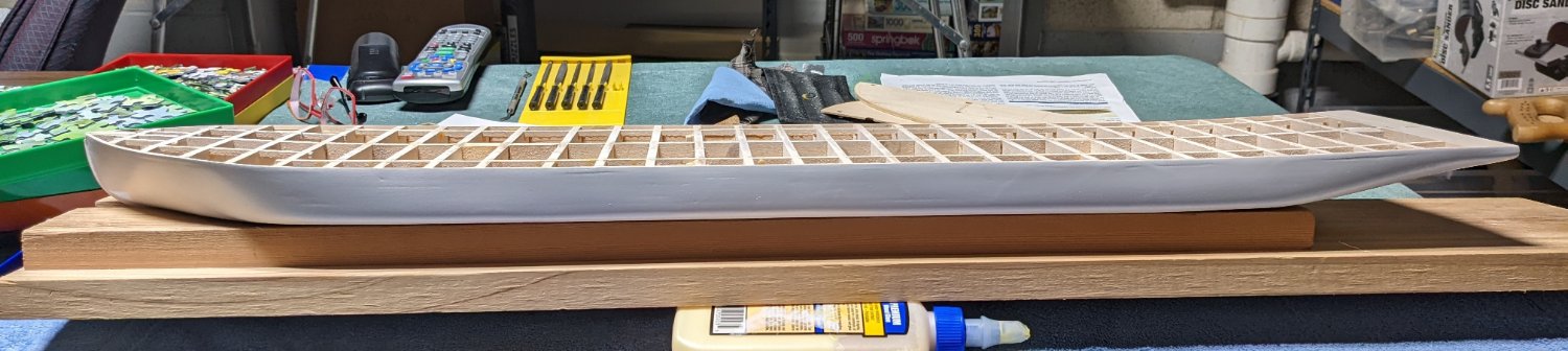
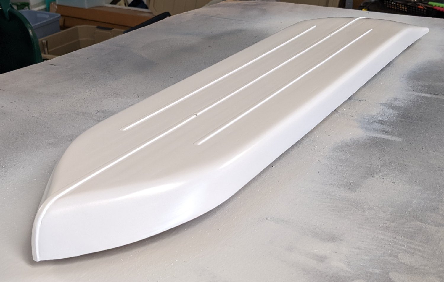
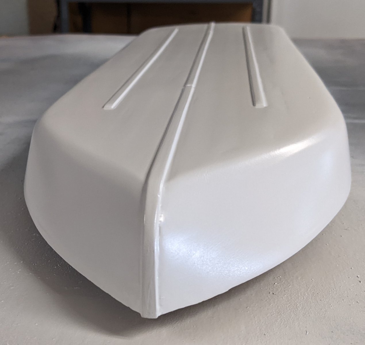
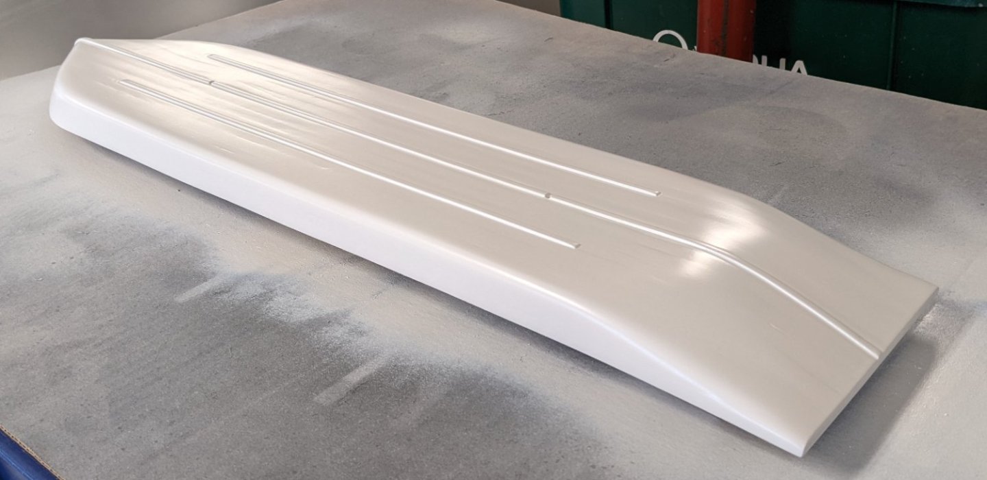
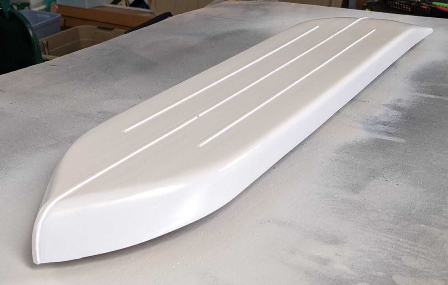
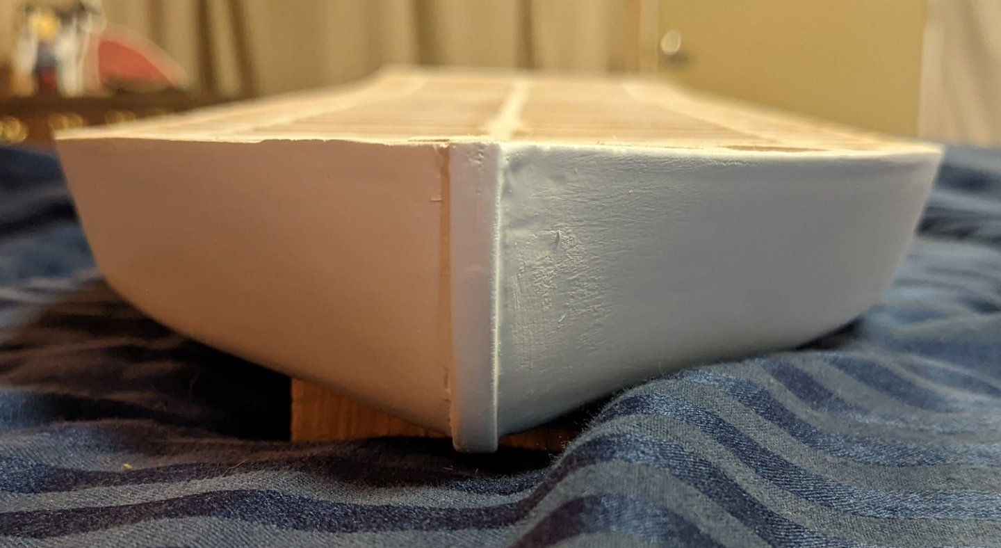
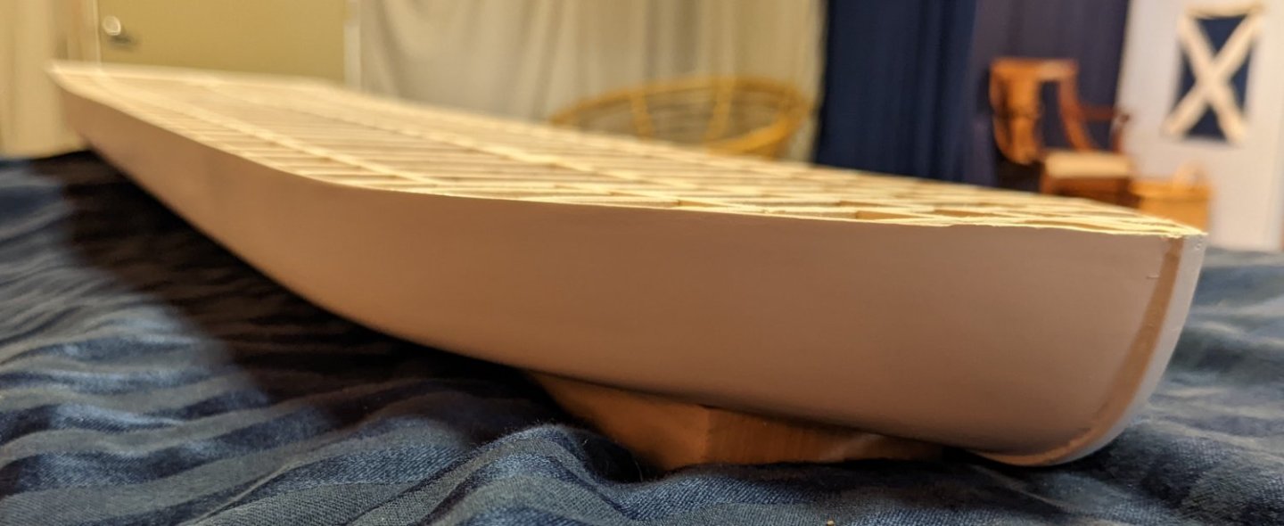
Brian, Thanks for that link. It is interesting to see all the changes over the years. Speaking of links, the link you sent me in a previous conversation showing the 3D virtual walkthrough of the Chaperon is fantastic. I really like it. Anyone building the Chaperon and wanted to know what it really looked like need to visit that link. https://www.jensmittelbach.de/steamboats/chaperon/index.html Actually, in the above link is shows the forward compartment walls. Looks like the builder of the real Chaperon also followed the written instructions and reversed the parts in the diagram. 🙂 Not much else to report other than the final coat of paint is on the hull. I am ready to put on the deck. Like in your build, I plan to plank the first two decks. I think a planked deck looks better than an etched deck. Beside, "why do something easy when you can make it hard"? Actually I say that, but planking the deck should be pretty straight forward. I have the 1/32"x1/8" planking ready to do. Just need to keep track of all the notches in the deck. It is amazing what some filler and a few coats of paint will do to a model. Covers a lot of sins... and lack of planking skills 🙂 Actually,,,, now that I look at it.... it probably is too good for a riverboat. I am sure the real Chaperon never was this smooth. I probably should have left a few plank lines 🙂

- 158 replies
-
- 3
-
-

-
- chaperon
- Model Shipways
- (and 1 more)
-
Eric and Brian, I really appreciate both of you taking the time to respond. I was looking at brucealanevans build log and looks like he followed the written instructions and reversed the pieces in the diagram as it appears his walls are on the outside of the posts. Now that I have had time to think about this I do not think it is critical either way - just depends on what look you want. When I get to that point and start dry fitting the pieces one way or the other will call my name. Again I really appreciate your responses. Brian, Thanks for heads up on parts 37P/S and the picture of the vent pipe for the safety valves. Both will save me some headaches down the road.
- 158 replies
-
- 2
-
-
- chaperon
- Model Shipways
- (and 1 more)
-
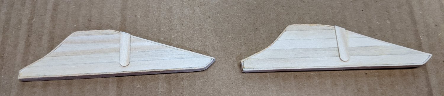
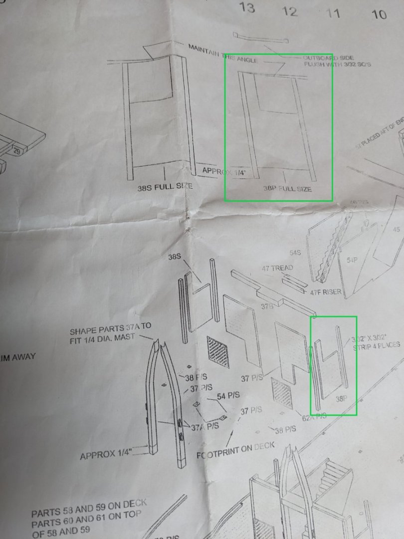
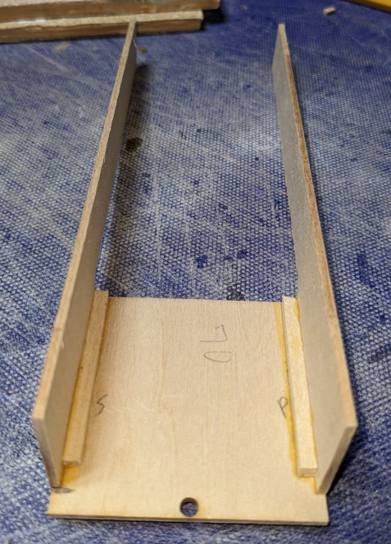
Boiler tank doors have been added along with what I call handles to the doors. Steam bar, mud tray, and backward facing dials have been added. At this point I am going to hold off on the safety valves. What I would like to do is have them attached to a pipe that winds around and eventually connect to the smoke stacks. The challenge here (or me anyway) will be to get three holes drilled in a 3/32" pipe and have it bend around to connect to the smoke stack. I plan to create that bent pipe and if successful then attach the safety valves to the pipe. That might be easier than first gluing the safety valves to the boilers and then try to bend the pipe to match the valves. All that will come a little later, I need to get back to completing the hull painting. But before I do that, I was looking ahead and it would seen there is a little issue with the foreword compartment diagram. Either that of I am totally confused.... I know I am not going to explain this well, but I will give it a shot. Please ask questions if I am unclear. In the below diagram I am only talking about part 38P, but it applies to 38S also. The written instructions are show below in italics. Begin by gluing 3/32" square strips to parts 38P and 38S. Do this over the full size plan shown on plan sheet 1. Note that the outboard sides of 38P/S will be down during this step. The questionable part of above is there it says "Note that the outboard sides of 38P/S will be down during this step." Problem is, in the diagram below, it looks like it is showing 38P with the outboard side up. To me in order to maintain the correct angles for 38P/S, they should be reversed. That is piece 38P should be layed (outboard side down) on the diagram labeled "38S Full Size" and piece 38S should be layed (outboard side down) on the diagram labeled "38P Full Size". Brian and Cathead.....Am I correct or really confused at to what I am doing here?

- 158 replies
-
- 2
-
-
- chaperon
- Model Shipways
- (and 1 more)
-
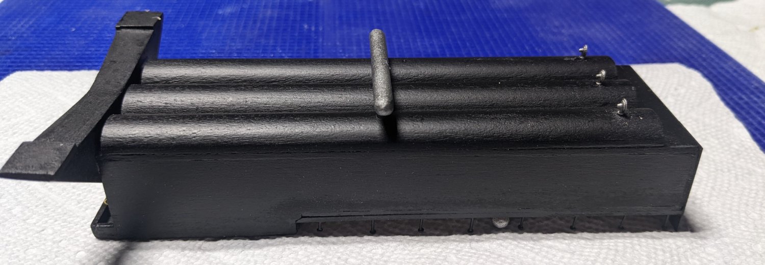
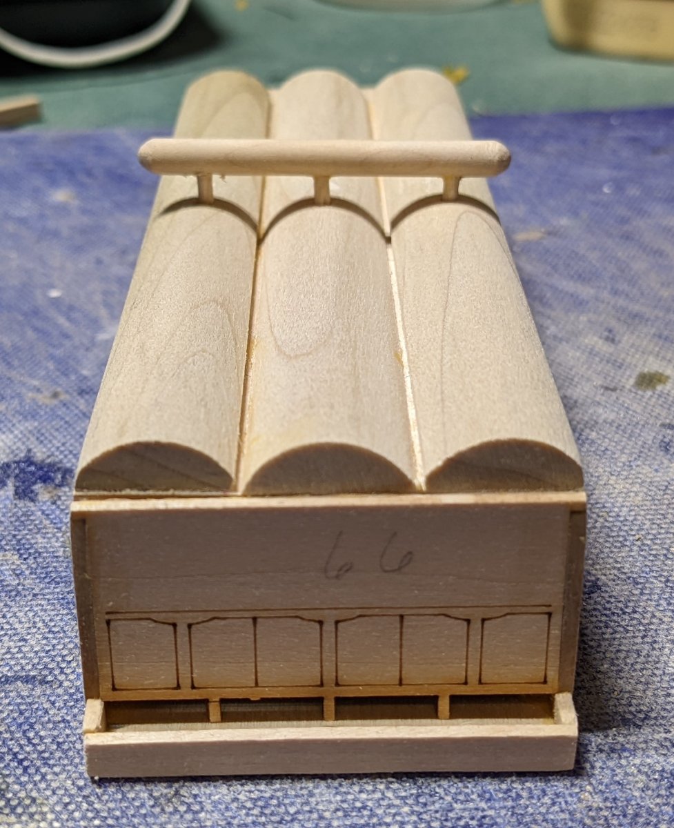
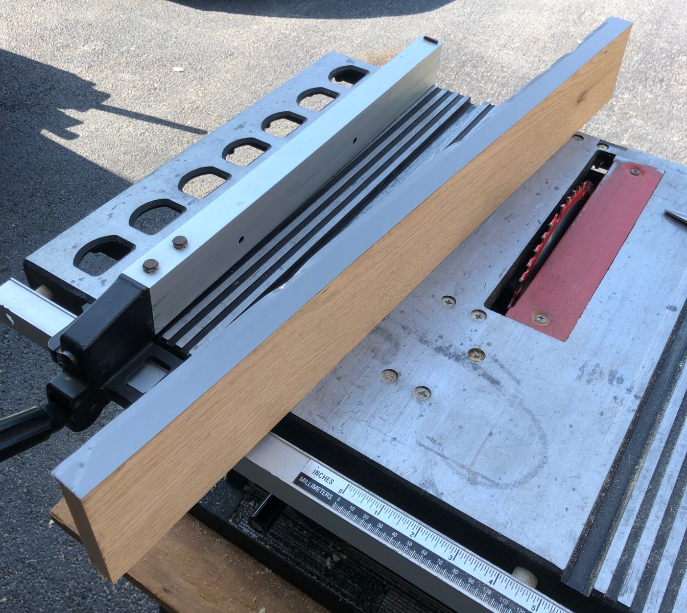
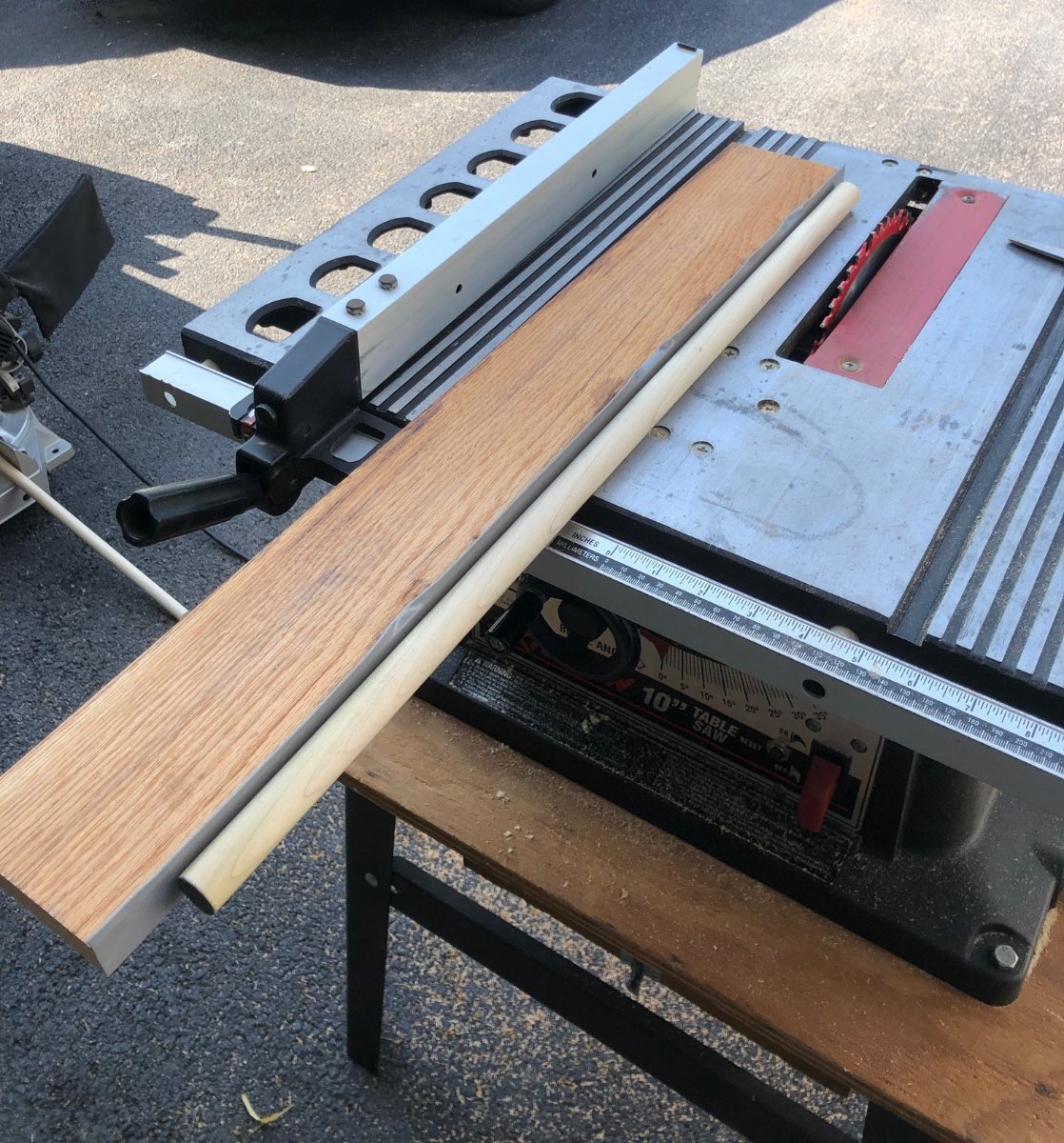
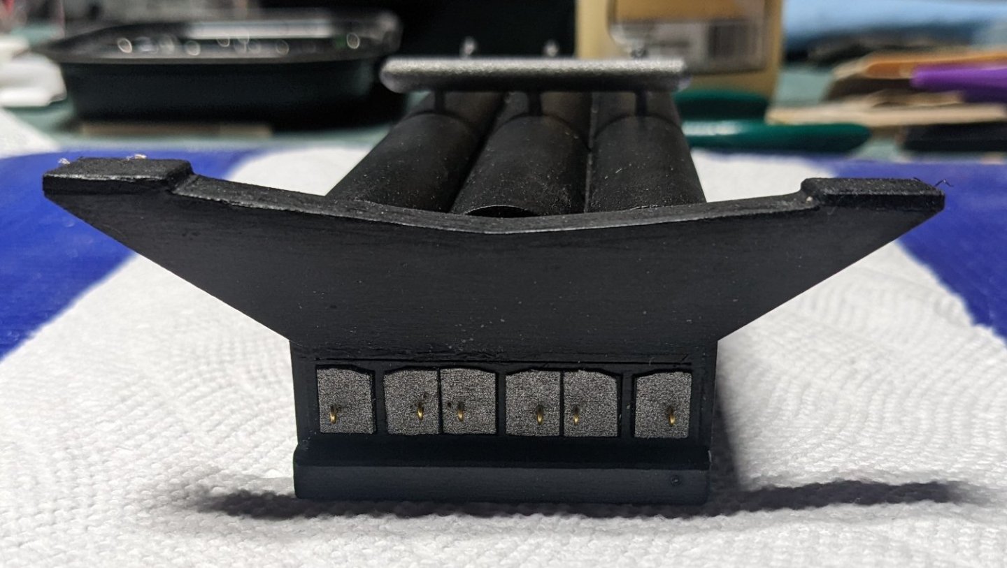
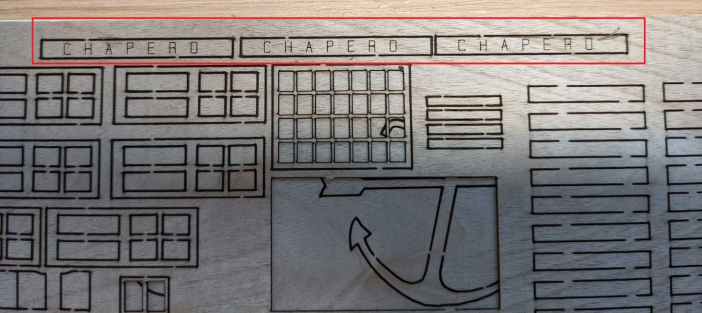
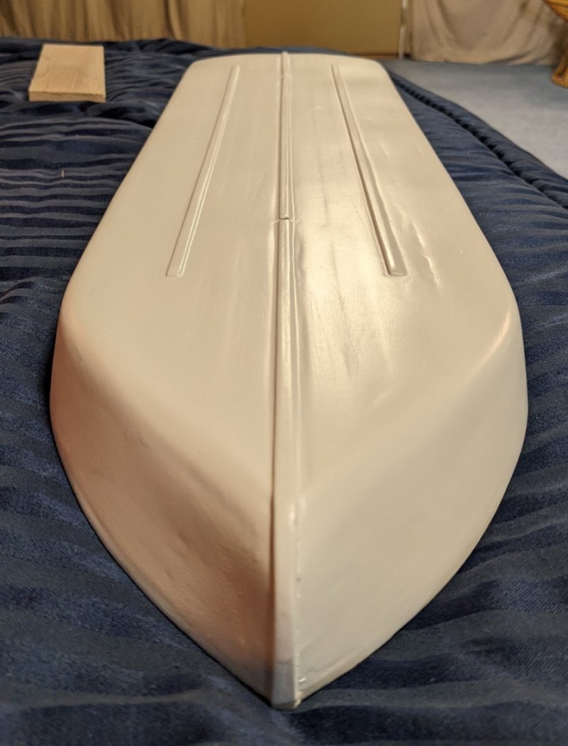
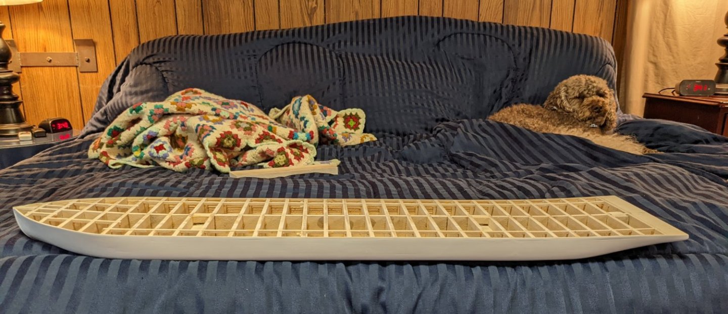
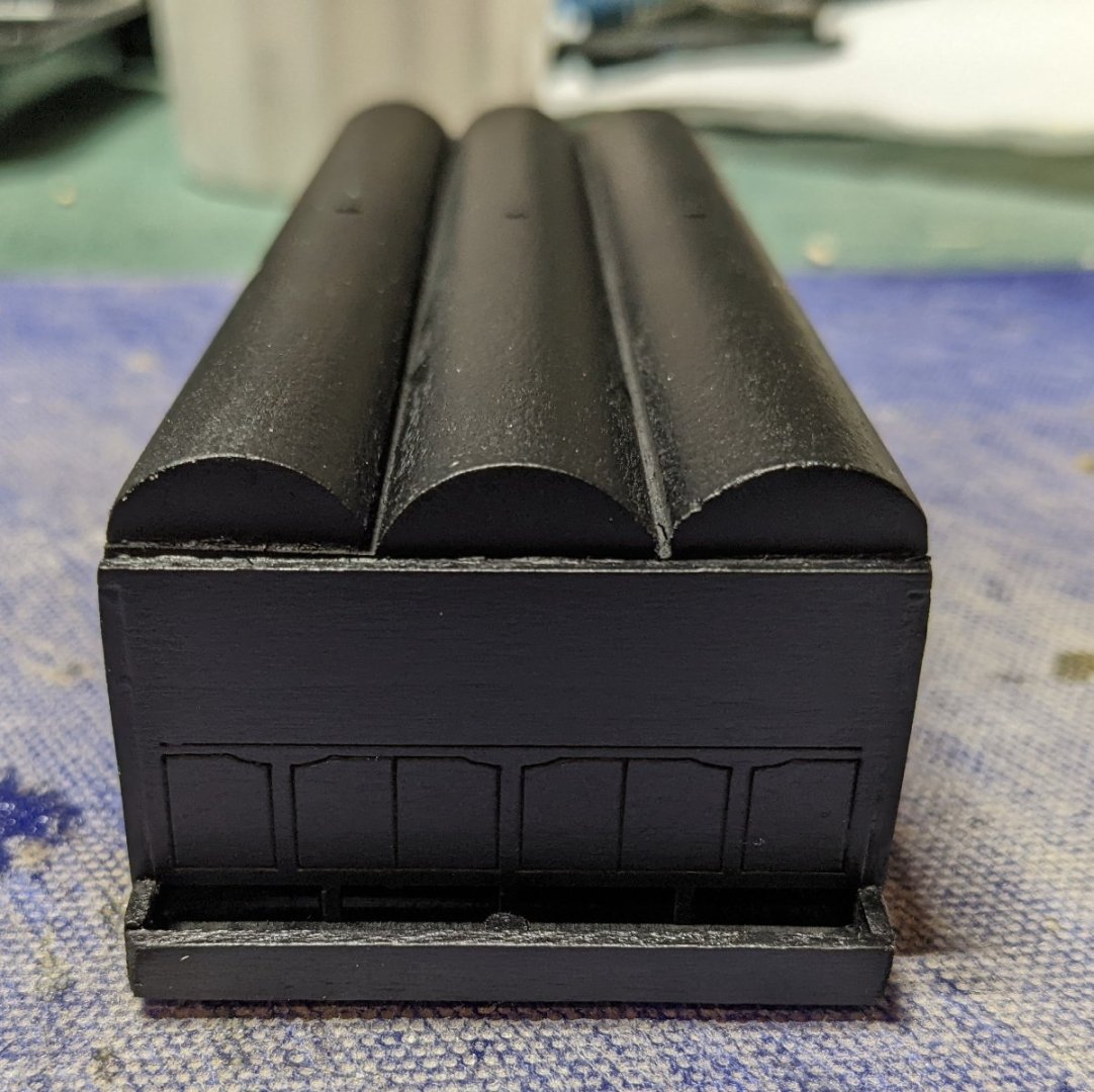
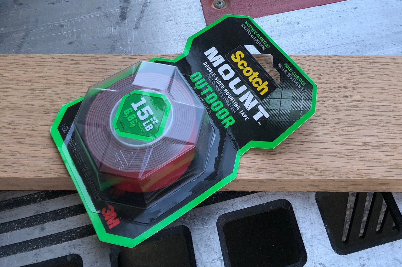
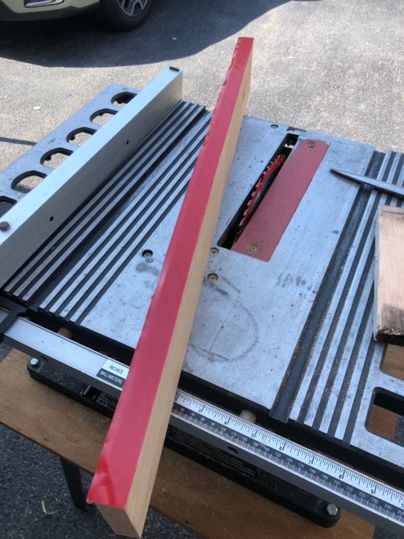
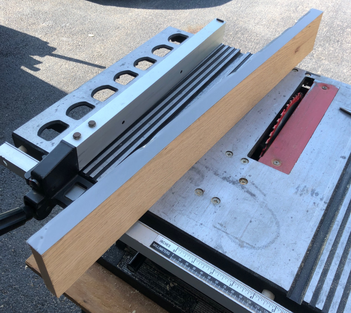
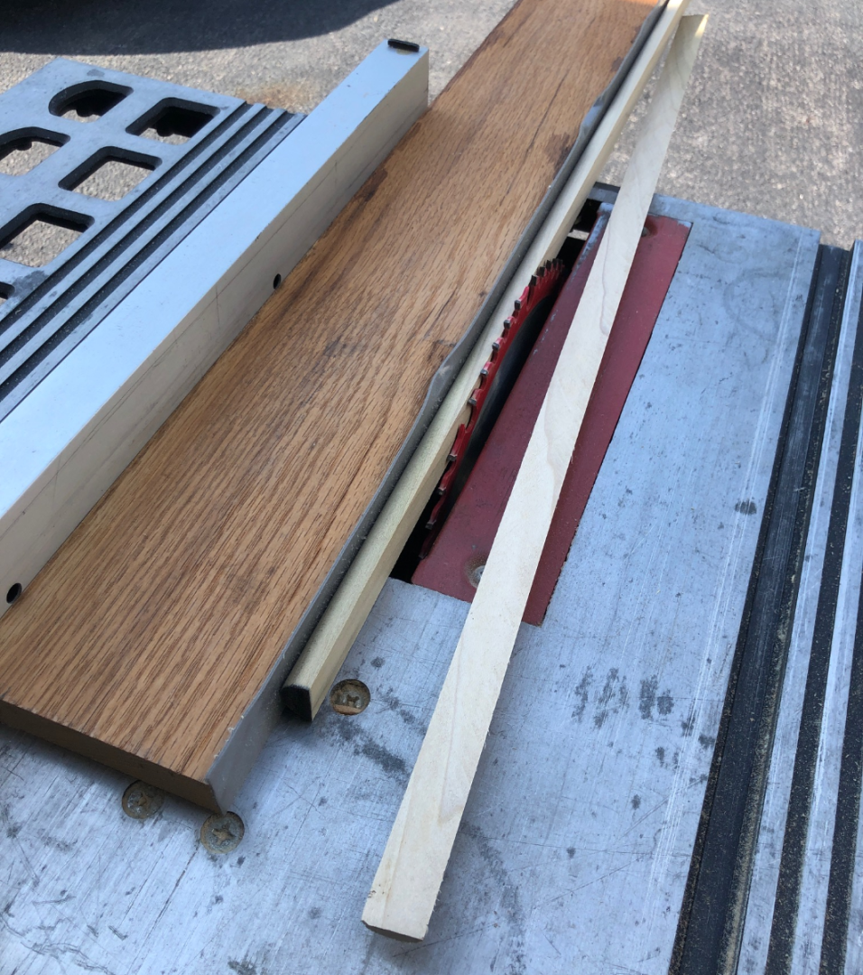
I just noticed on the 1/64" wood sheet (LC-24) there are three pieces with the name CHAPERON laser etched. On all three pieces the name CHAPERON is missing the "N". Not a big deal as I can somewhat easily add the missing "N", but since it is laser etched and all it would not look the same. A quick note to Model Expo and a new part was quickly shipped out. I really like that policy of Model Expo. I am finally almost completed the hull. Looks like I have one more final coat of paint to apply as there are still a few rough spots, but all and all, for a novice like myself, the hull is looking pretty good. On the bottom you will notice I added two extra keep parts. Even though I play to screw the hull to the frame I made earlier to work on, in the end I plan to mount the final ship on a glass shelf with no pedestals. My other models in the glass case all just sit on the glass, so I figured this one would too. Thus in order for the hull to lay flat on the glass, the two extra keels were required O All work on the boat is constantly monitored and supervised by a pair of watchful eyes. While last last set of paint dries I have started playing with the boiler. Note in the making of the main boiler frame I added some extra strips of wood inside just to give me a little extra gluing area. Not really required and way overkill, but it sure makes gluing walls easy when you have a little more gluing surface Here I also added two cross pieces, as the thin wood walls tended bend in. These keep the wall straight before the bottom was glued on. On the bottom of the boiler nails are to be use to simulate support feet for the boiler. There are two problems here. One is that the boiler walls are only 1/16" thick. There is no way someone of my skill would be able to drive a nail into the side of a 1/16" piece of wood. The other problem is that the supplied nails are too short. The distance between the bottom of the boiler and the floor is only a little longer that the supplied nails. Only solution I could figure out was to add a small wood strip on both sides of the boiler. That way you have a much larger area to nail into and the distance between the boiler and the floor will be a little less - thus allowing more room to drive the nail into. Moving on to the smoke manifold, instructions call to start by gluing part 74 to 73. From there you build the other parts (75,76,77) around them. Problem I felt with that approach is that the most important part of the smoke manifold is part 75. It must be perfectly flat to later on accept the smoke stack on top of it. With all the weird angles involved with the smoke manifold, starting with 74 to 73 and building around them would make it pretty easy to end up with part 75 not flat. Thus I started with gluing part 75 to 73, insured that was flat, and then build the other parts around them. Thus the final smoke manifold. Then after a little filler and paint,,, One additional touch I wanted to add was the simulated top of the three boiler tanks as others have done. It is a neat look. Basically it involves cutting 3/16" strip off a 3/4" dowel rod. Problem is, I do not have a table saw, but even if I did, I kind of like my fingers and not sure I wanted to take the challenge. Happily I had a close friend who has a table saw and not really in love with his fingers. He took on the challenge. For those interested, below are some pictures as to how we was able to complete this and keep all 10 fingers. Get some very strong double sided tape. Attach the tape to one side of a straight board Peel off the protective coating Stick the 3/4" dowel rod to the tape. Then run it though the table saw - cutting 3/16" off the dowel rod. Again,,,, this tape has to be strong. We are not talking scotch tape here. From there, cut the cutoff piece into 3 - 5 3/4" pieces. Below shows the pieces attached to the boiler. In front of the boiler doors is documented as ash pan, but the instructions only show a flat surface. In order to keep the ashes from spilling out onto the floor, I added some little walls around the ash pan. After a little paint, I see the extra piece of wood attached to the bottom of the boiler (with the feet attached) is coming loose. I just now noticed that. That probably happened when I was adjusting the nails to be all the same length. Nothing a little more glue can't handle. Now I just need to add the smoke manifold, boiler doors, steam gages, and safety values that this should be ready to go. It will be awhile before the ship is ready for the boiler, but I wanted to get this little side project going while I was working on the hull.


- 158 replies
-
- 5
-
-
- chaperon
- Model Shipways
- (and 1 more)
-
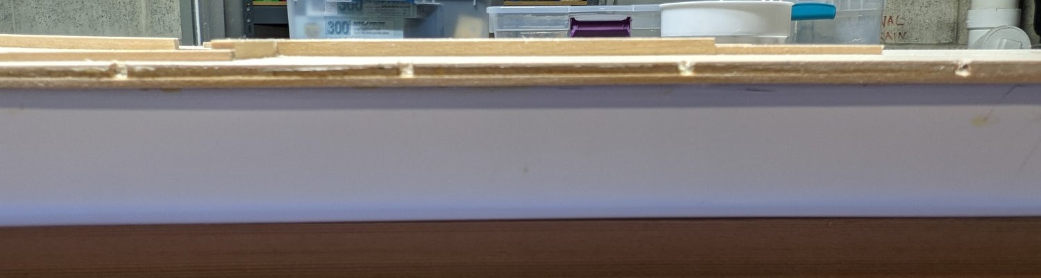
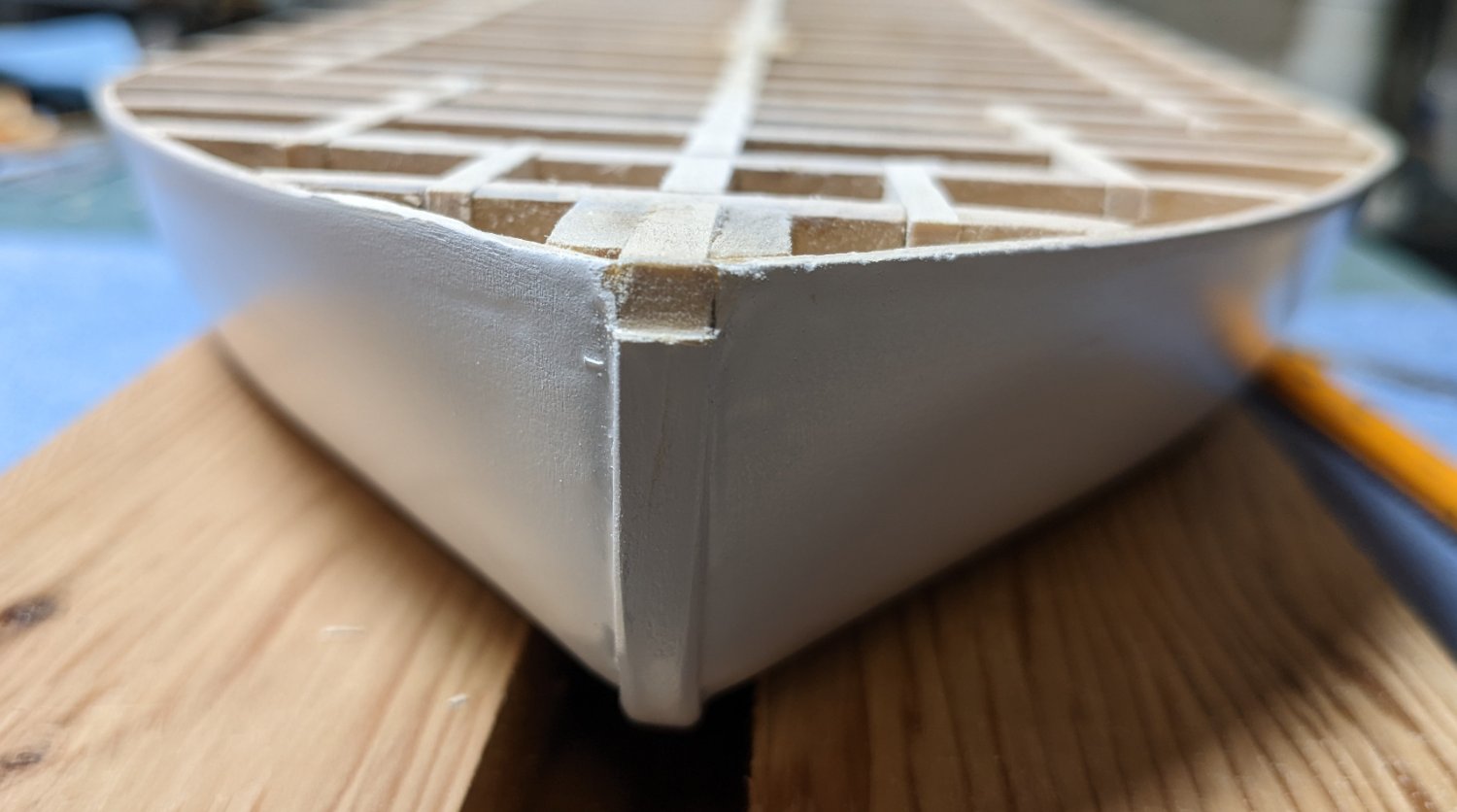
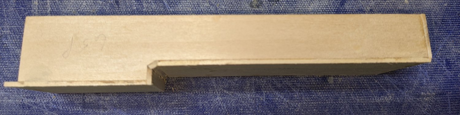
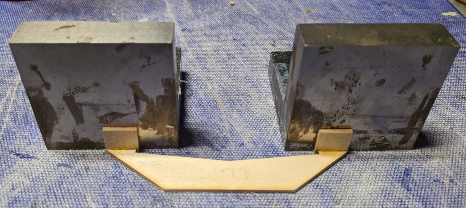
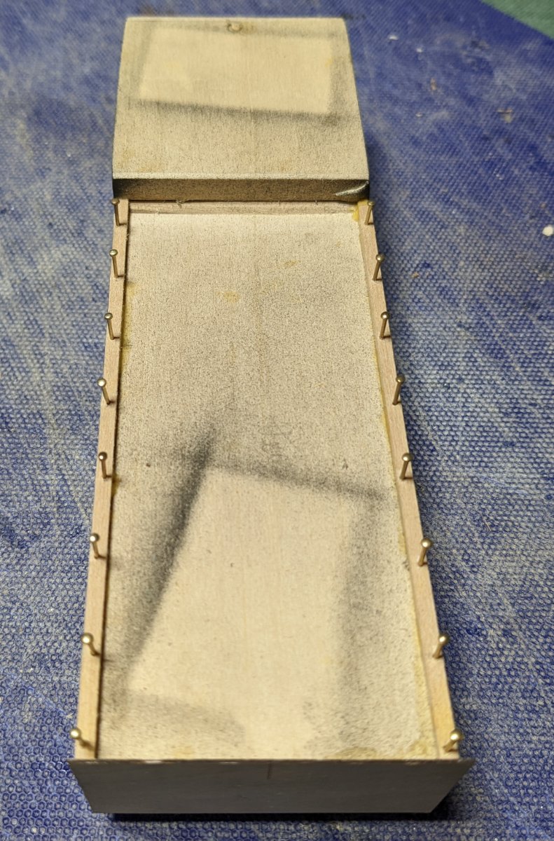
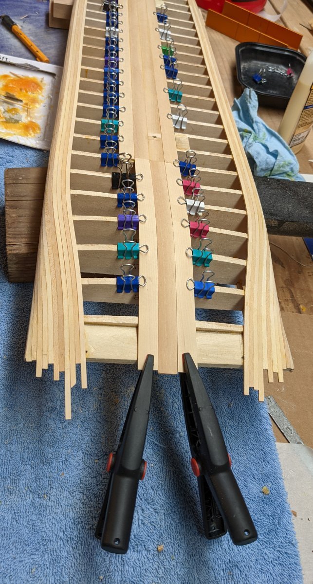
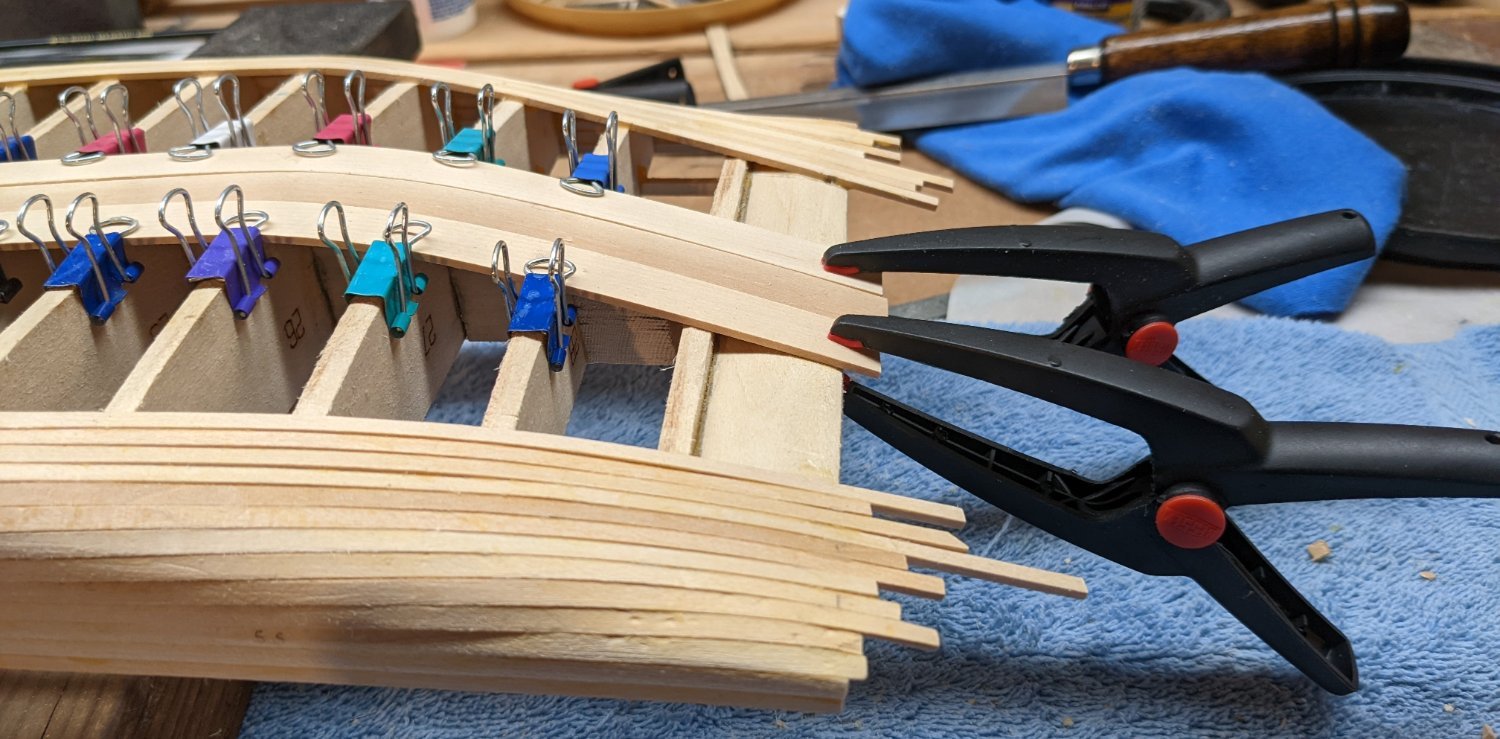
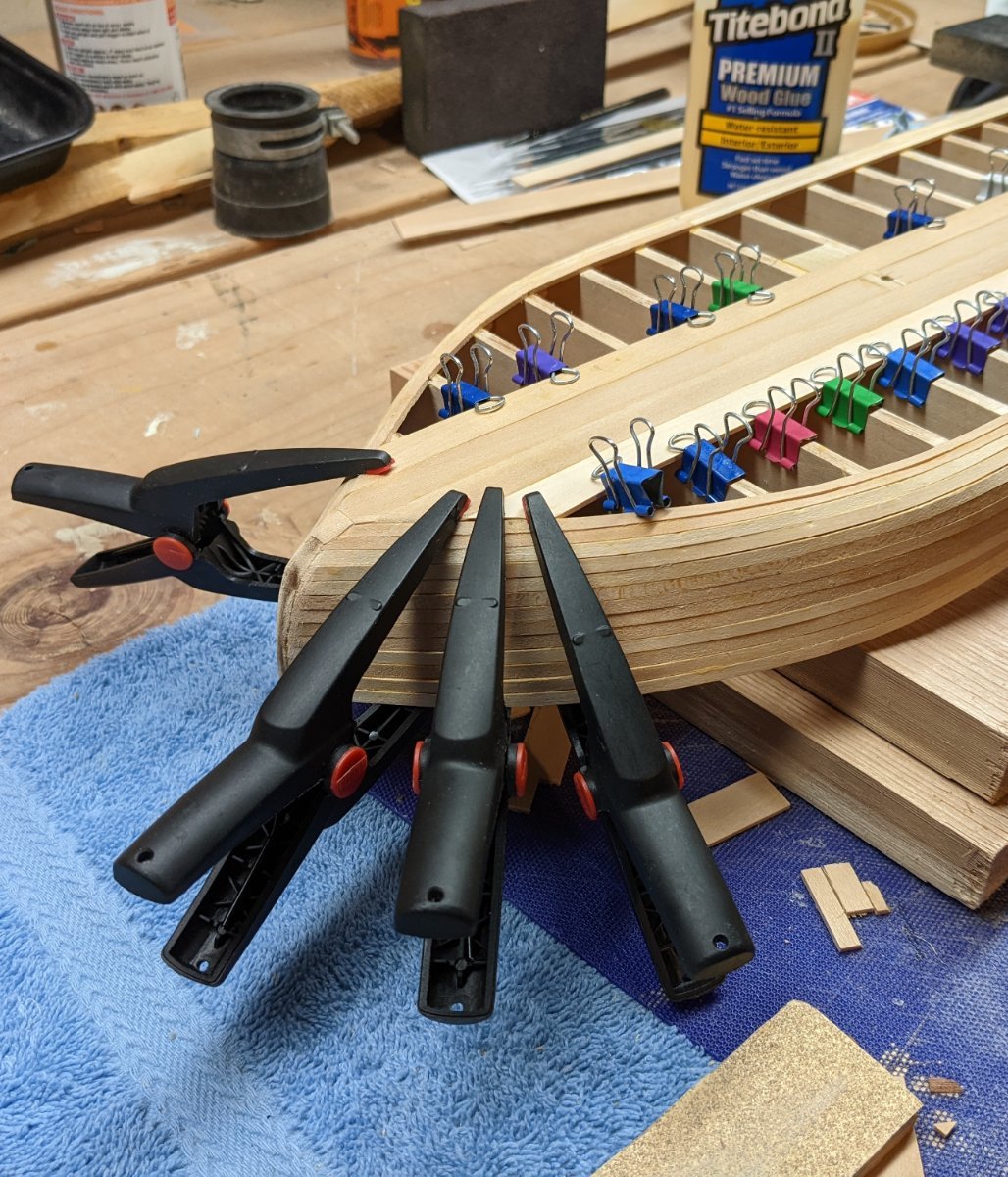
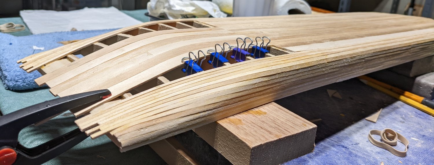
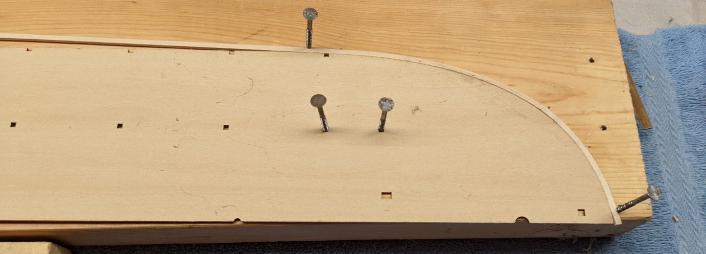
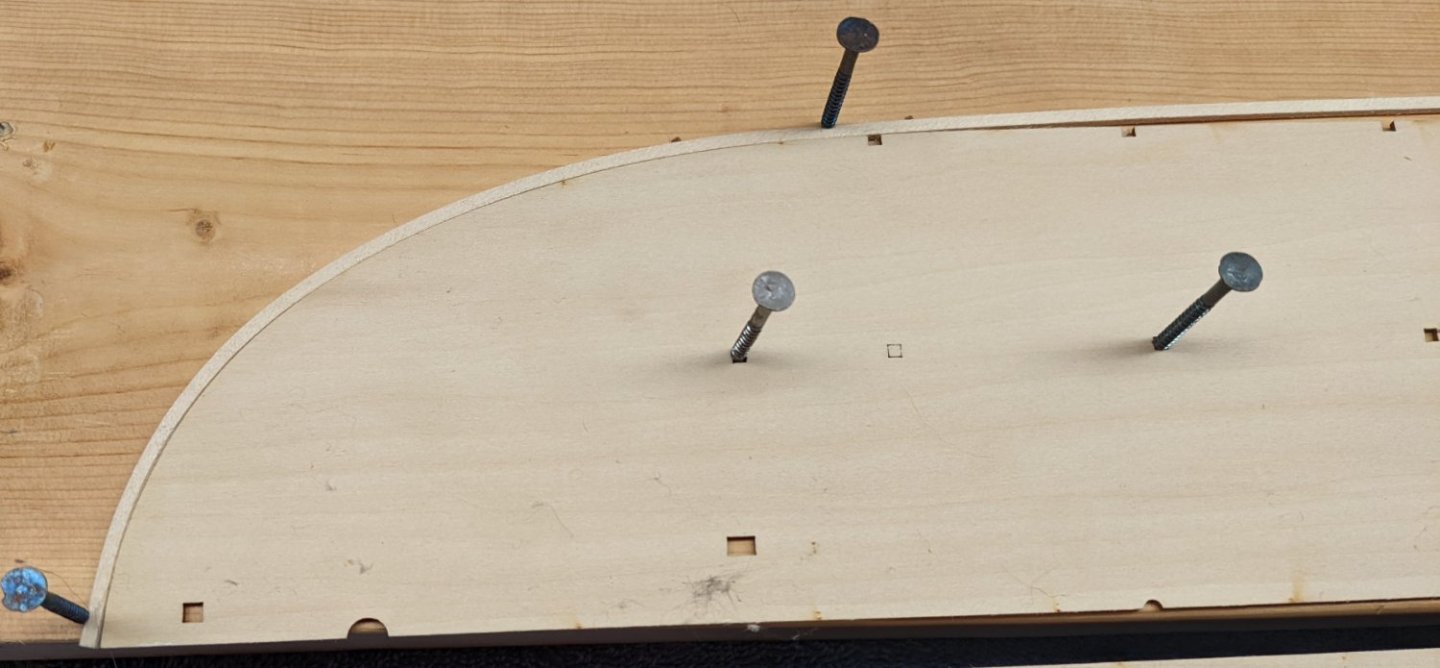
Brian, If you are happy with the filler you use, I might suggest you stick with it. I can not really say Filla in-a-bag is better or worse than what you are using - just different. I have had great success with Elmer's Carpenter's Wood Filler too. And in some ways, for quick litter filler applications, Elmers is much easier and quicker to use. Back to the build Later on in the build, once the deck is installed, a 1/16"x/1/4" rub rail strip is to be glued around the entire deck. Problem is the deck (1/16" thick) overlaps the hull by about 1/8" on each side. Thus the rub rail will will hang down from the deck with only 1/16" to glue the rub rail. For someone with my limited skill that will pose a problem. Probably way overkill, but for me it makes sense to increase the edge of the deck to better accept this rub rail. I decided to use a 1/16"x1/8" strips to increase the outer edge of the deck. The 1/8" plank around the decking pretty much takes up all the extra overhang space. In the below pictures it shows the 1/16"x1/8" wrapped around the curved parts of the bow and stern, just to get the overall curve. Once dry, they will be glued just inside the decking to make a better gluing surface for the later rub rail. Once dry the curved pieces are glued onto the outside edge of the bottom side of each deck section. Below shows the end result. I have not seen this done in any of the other logs, so I guess this really is overkill, but it makes sense to me.

- 158 replies
-
- 6
-
-
- chaperon
- Model Shipways
- (and 1 more)
-
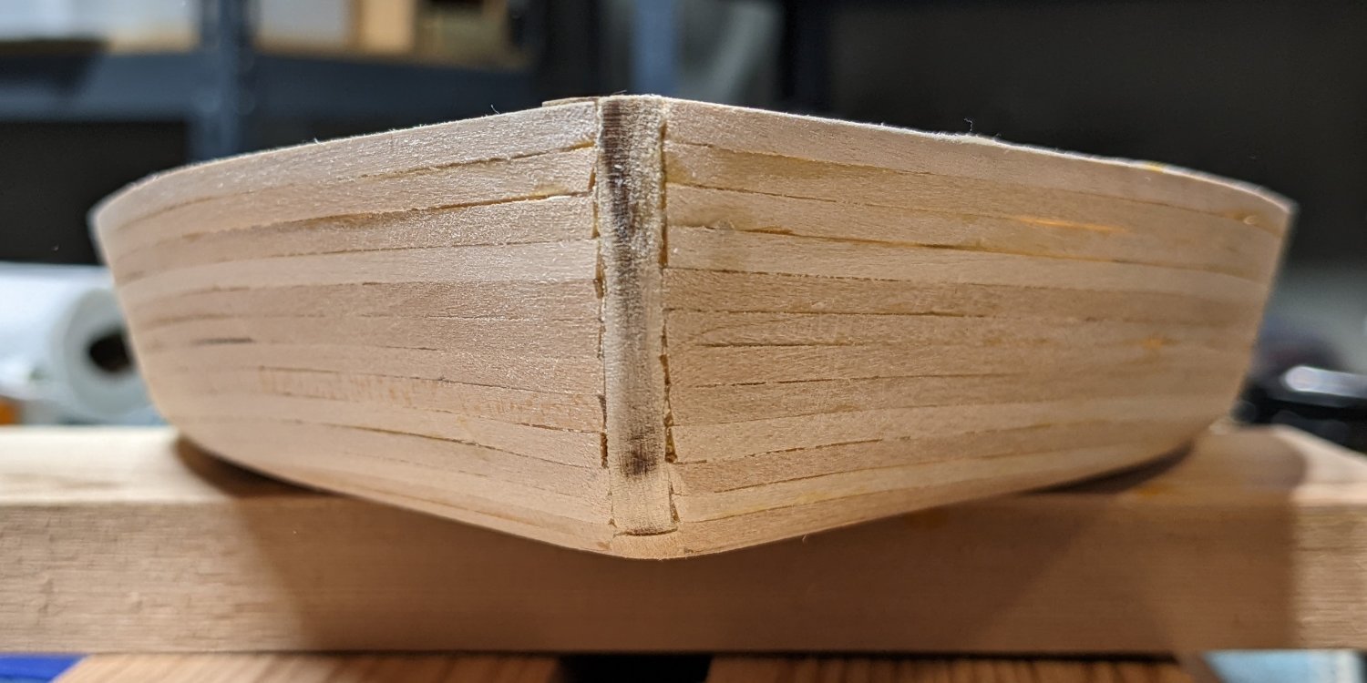
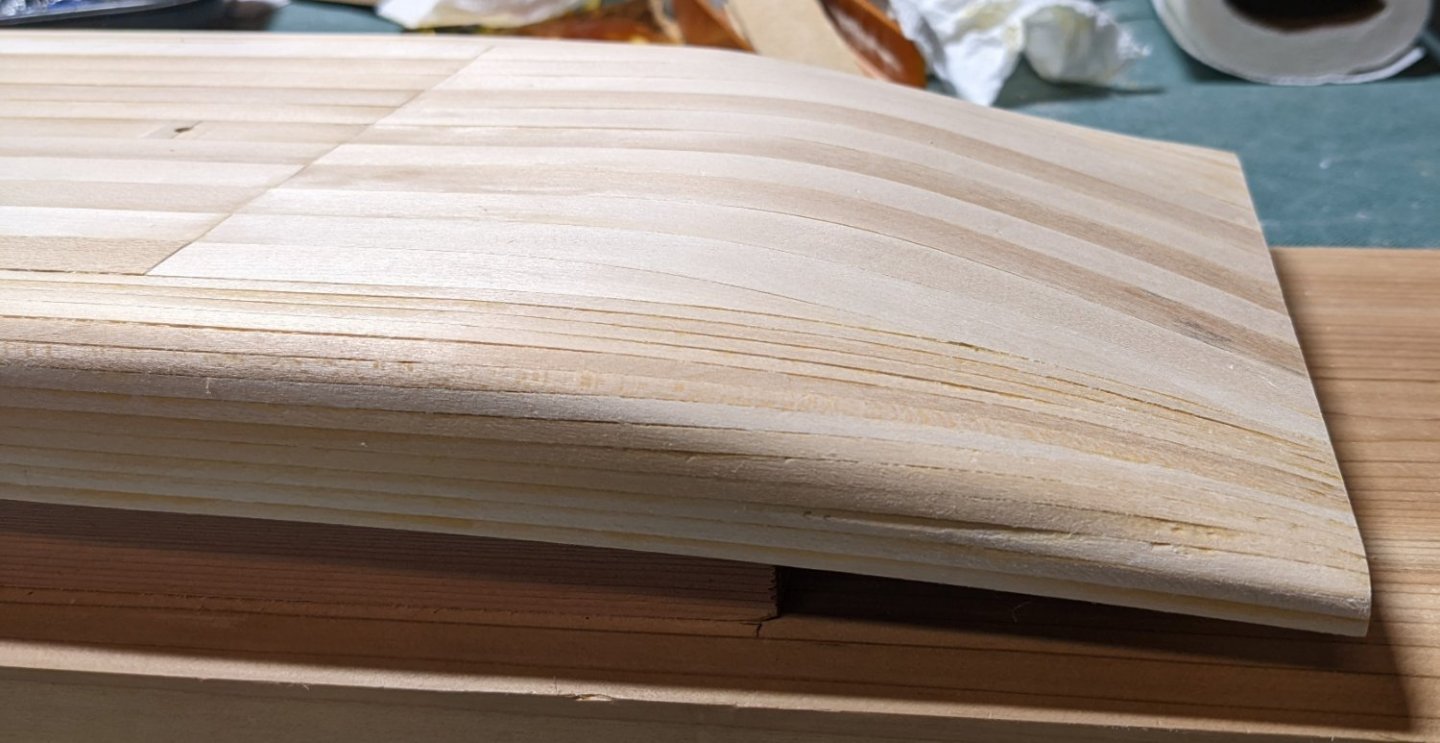
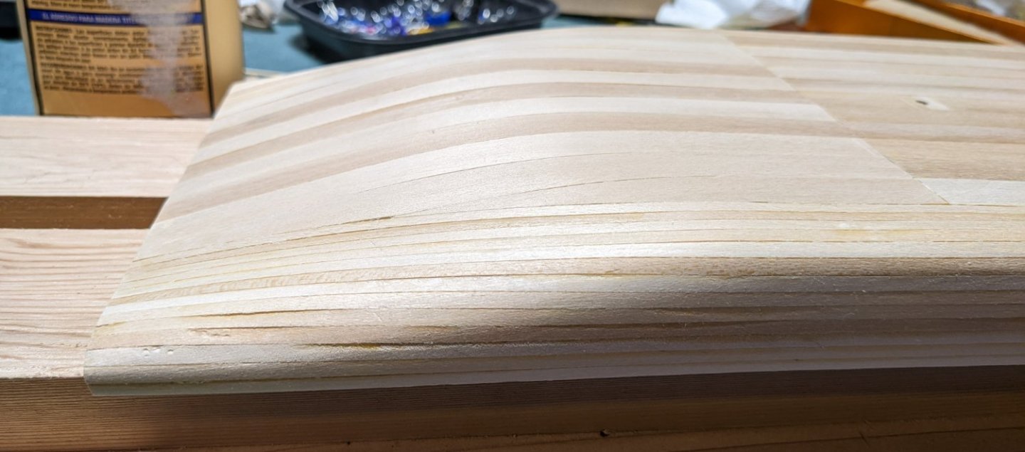
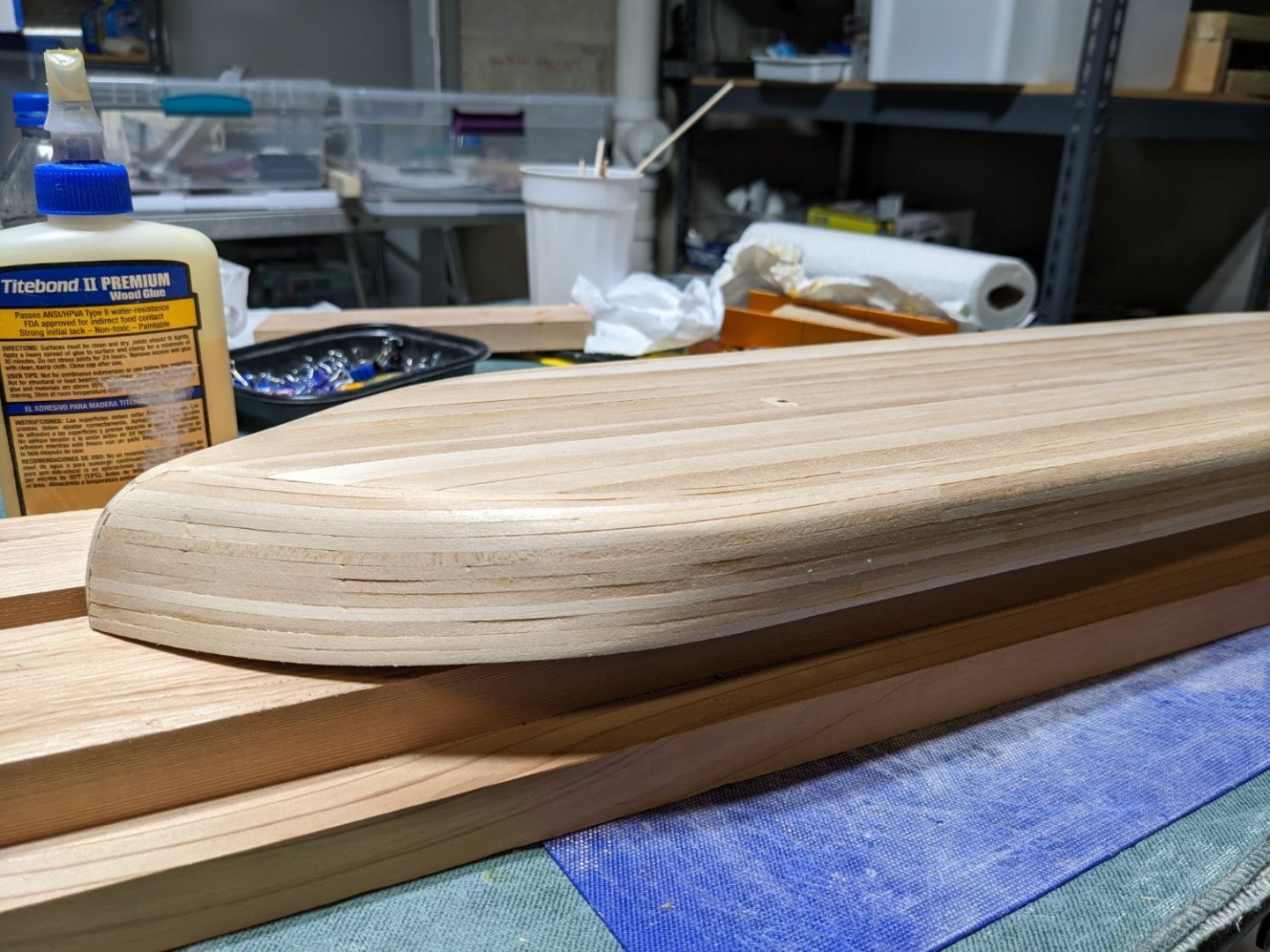
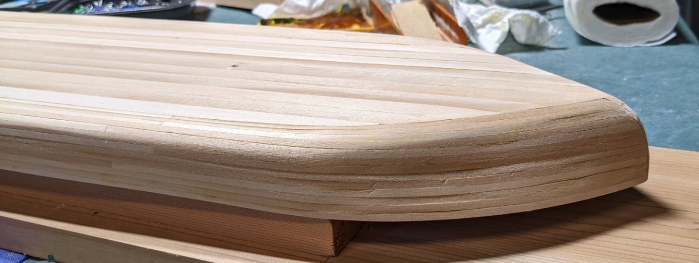
After soaking and drying the keel, it was applied to the hull and a light sanding. It would seem the keel at the very end did not go on straight... Not sure it is worth tearing up and fixing as no-one will see the bottom of the hull, but we'll see what happens when I take a closer look at it later on. I mentioned earlier about the stern of the boat and being a little "untidy" looking. Even after some sanding it still does not look right. And even though the paddlewheel will cover most of it up... Just feels wrong to not plank it. I know I said earlier I would not overlay this with planking,,,, but I just could not help myself. Now on to the filler. In may case the filler I use is called Gork's Goodfilla FIlla in-a-bag It comes is a number of colors, but in my case I just choose Natural. One thing I like about it is that it is water soluble and goes on very smooth. To get a really smooth finish after application you can wet your fingers and rub over the filler spots. The filler will re-activate and you can get a glass like finish. Of course after it dries you it is also very easy to sand.


- 158 replies
-
- 6
-
-
- chaperon
- Model Shipways
- (and 1 more)
-
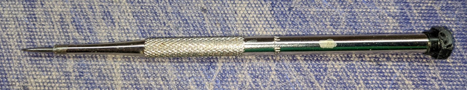
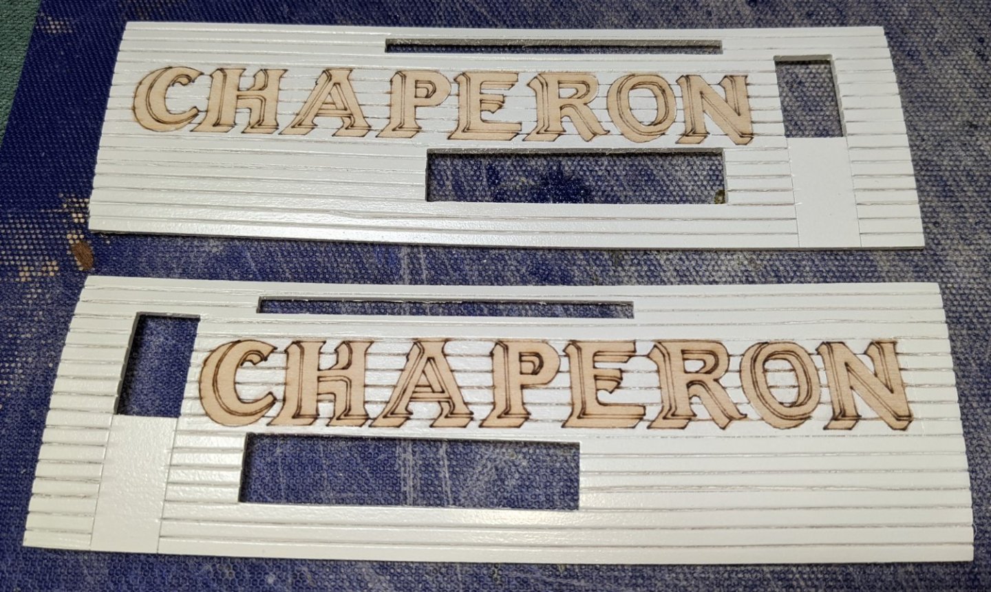
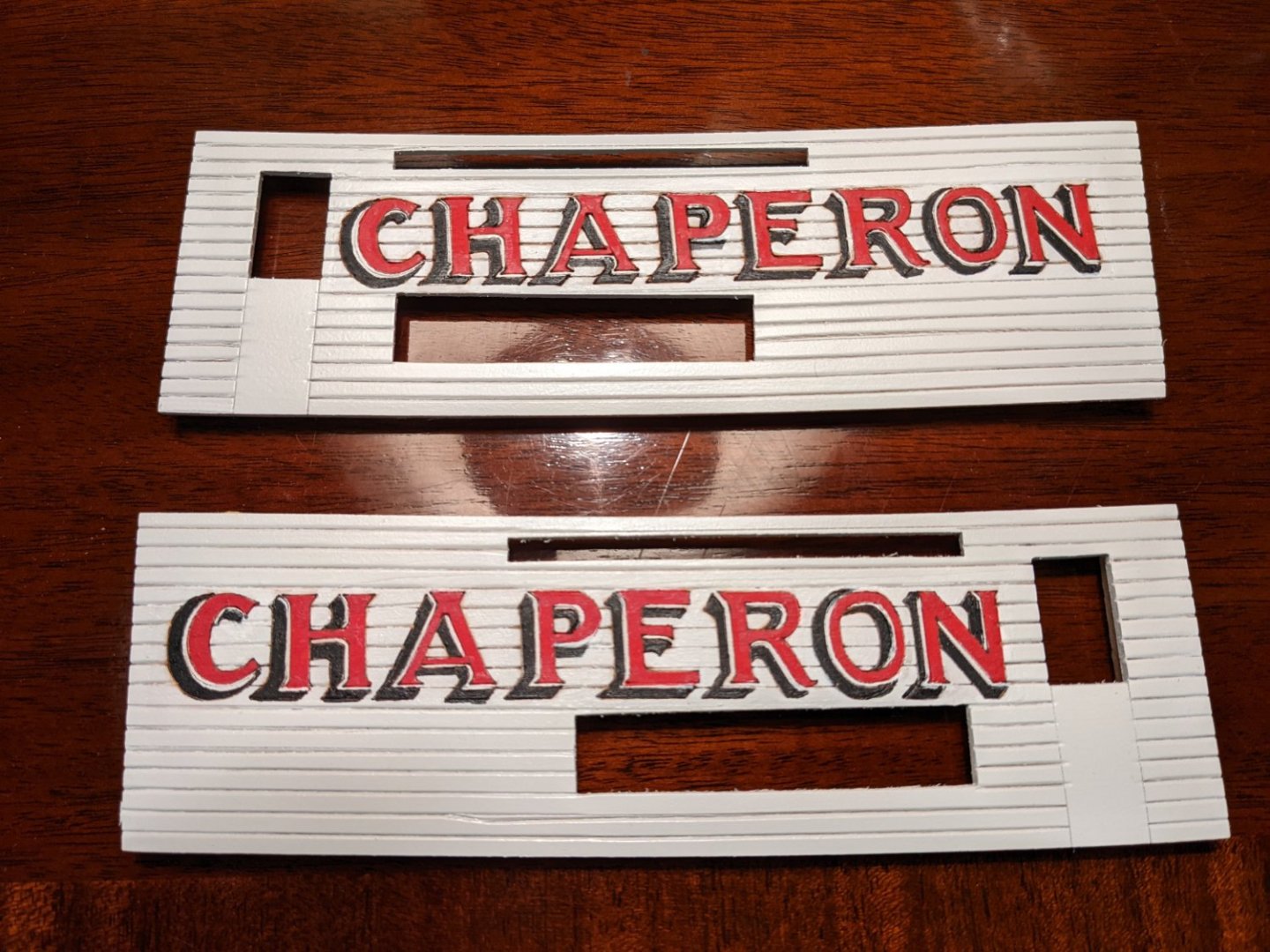
Brian, Thanks for bringing me back to reality.... To me looking at the stern of the hull, even before final sanding, it looks pretty rough. But I forgot...while this may be the end of the hull, it is not the end of the ship. That paddle wheel comes after the end of the hull. So you are correct.... after final sanding the the addition of the paddle wheel, it will not be noticeable. Starting soaking and bending the keel to fit the hull. A few handy clamps and rubber band easily set up the keel for bending around the front of the boat. As I mentioned earlier, the etching on the pieces that are supposed to simulate planking is really thin. Not sure if it was just my model, but any coat of paint would easily fill in the groves. I have been thinking (and worrying) since the start of the build about these thin etched planks and how to make the etch lines looks like planking with out filling them up with paint. A more experienced modeler knows all this stuff, but for me it is new. Sent a note to Brian (mbp521) asking about this and he mentioned the solution is to use a scribing tool to enhance the etched lines. Seems like a simple solution, but it was news to me. Below is the etching tool I used. It is a slow process, and you have to etch every time between paint coats, but in the end, the simulated planking looks pretty good. Below are the pieces for the rear cabin structure. The pock marks on the lower right wall are my fault. After sanding, I use paint thinner too clean up the pieces before painting. I normally use this as it dries fast and you can paint it fairly quickly..... Problem was,,,, I did not wait long enough as I assume there was still paint thinner residue as the next coat of paint really balled up and had to be sanded down again. Looks like I still need another sanding and coat of paint. As for the CHPERON letters,,,, they are still a work in progress. At this time I masked them off as a block and spray painted the white around them. I have since gone in with a very small brush and added only one coat of white paint between the letters. I need to add a couple more coats of white and then fill in the red and black letters. It will take a small brush and steady hand to complete those letters,,,, We will see how it goes, but so far I like the result And with letters filled in. We had some very close friends over for the weekend and when she found out what I was doing she volunteered to add the Red, Black, and White for the letters. Needless to say she has a very steady hand. Below are the forward compartment walls. One on the top left has the same issue as the larger wall above,,,, human error on my part with paint thinner. Still need to work on that one, but the others seem ready to roll

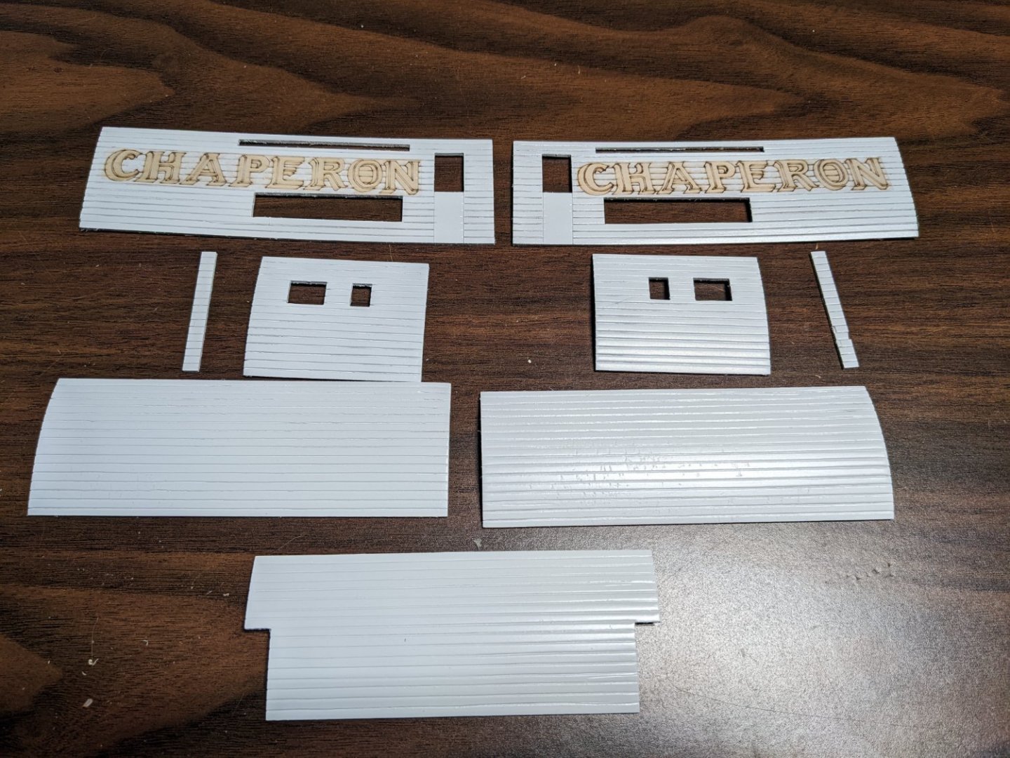

- 158 replies
-
- 6
-
-
- chaperon
- Model Shipways
- (and 1 more)
-
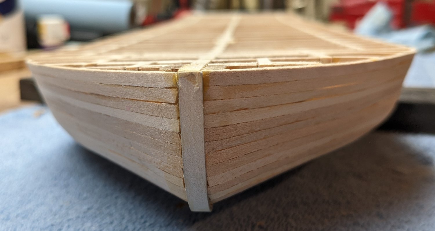
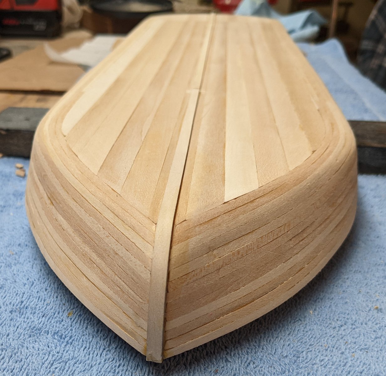
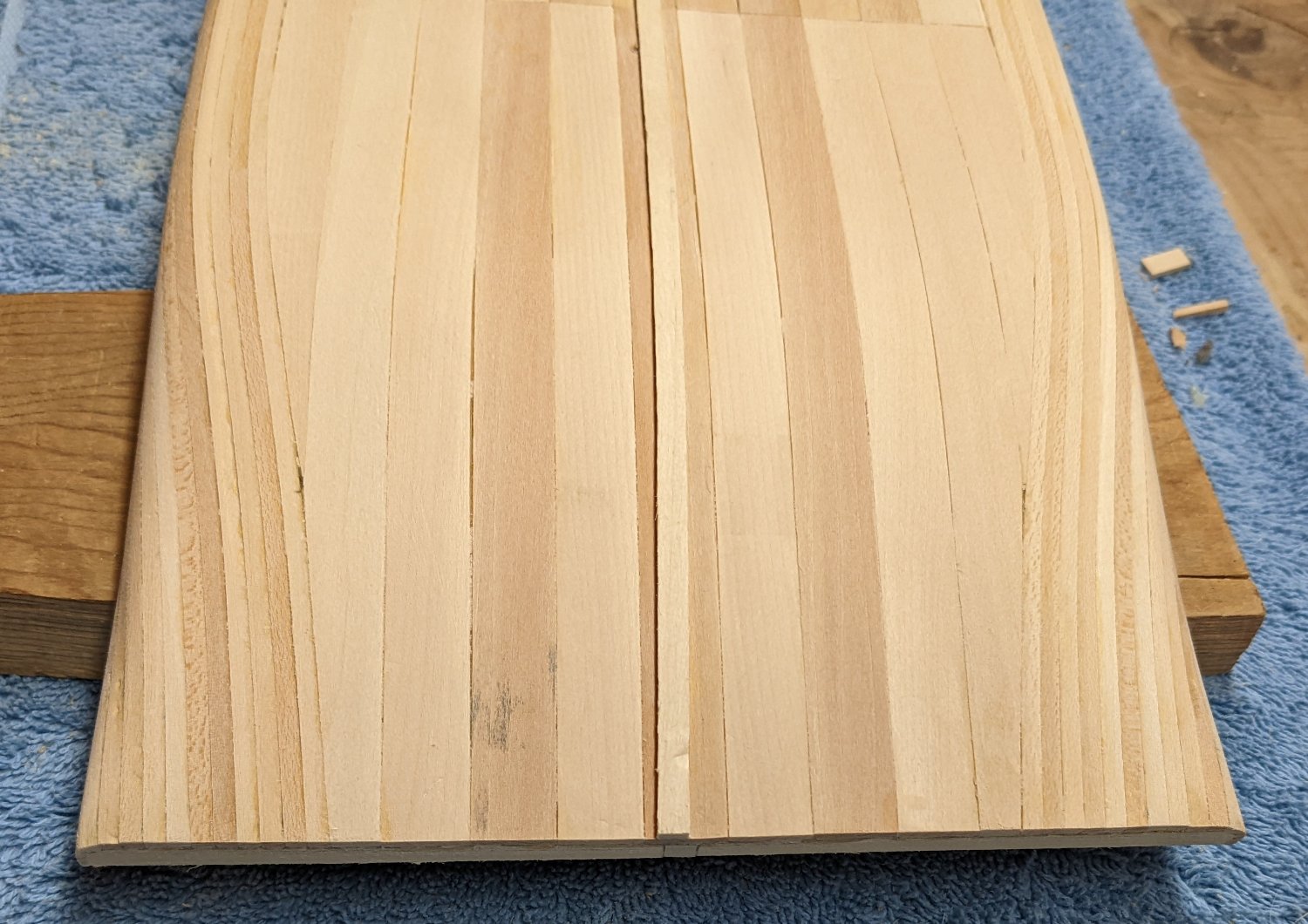
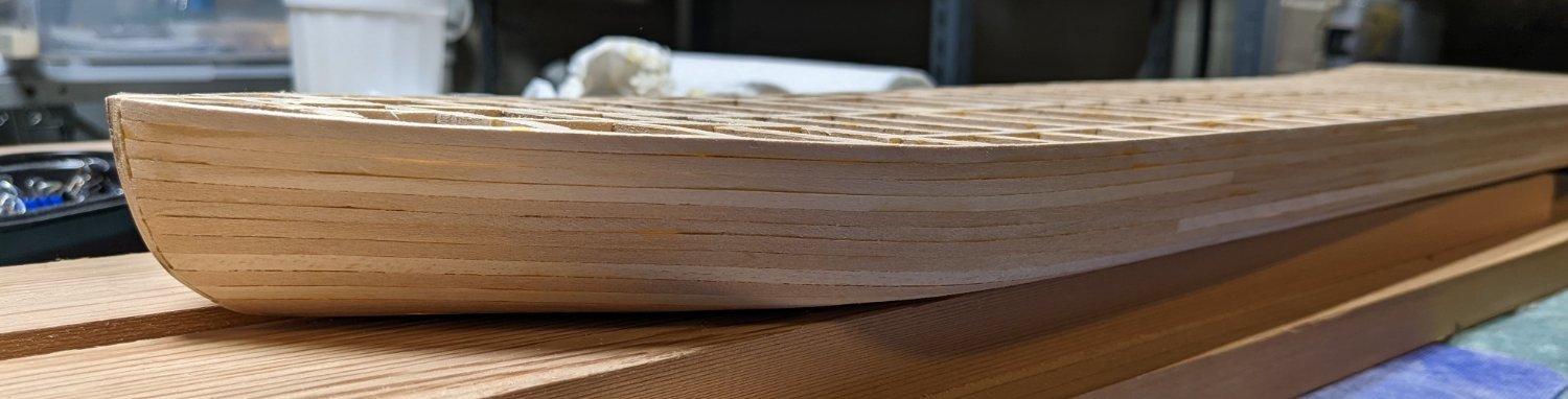
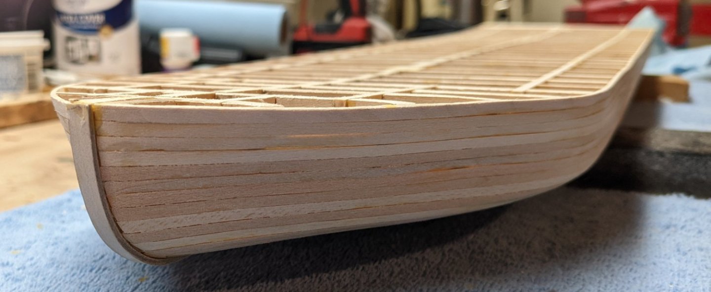
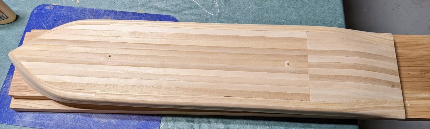
Did I mention before that this will be a painfully slow log.... Summer is here and it seems the boat building business has ground to a snails pace. With the side of the hull planking complete, time to start planking the bottom of the hull with 1/2" x 1/16" planks. Starting with the middle and work you way outwards. Again very little bending and trimming of these planks to complete the bottom. They more or less just fall into place. just keep working your way outward... Note the two holes in the bottom for the previously mentioned screws to connect model to the base stand. Only regret here, as you have noticed, I did not stagger the bottom planks. At the time I thought about it, but figured it was the bottom of the hull and it would be painted (no one would see it) so I thought I would just line up the planks. Again, not a big deal, but the straight line just seem wrong. I should have staggered the planks. Only part that requires any effort at all are the remaining pieces (below) to fill in the bottom of the hull. But will a little patience and sanding, these pieces also fall easily into place Below shows hull bottom complete and after an initial light sanding. I still need to add the keel so I held off on a full sanding until the keel has been mounted. One item I noticed as the very end of the hull where the planking meets the end part of the hull (part 29A) looks kind of rough... Even later on after a full sanding that area will probably still look unfinished. I am not sure yet, but probably the solution would be to overlay this area with at 5/16" plank,, just to make it look like one piece. I will see what it looks like later on after filling and sanding.


- 158 replies
-
- 7
-
-
- chaperon
- Model Shipways
- (and 1 more)