HOLIDAY DONATION DRIVE - SUPPORT MSW - DO YOUR PART TO KEEP THIS GREAT FORUM GOING! (Only 20 donations so far - C'mon guys!)
×

jpalmer1970
-
Posts
408 -
Joined
-
Last visited
Content Type
Profiles
Forums
Gallery
Events
Everything posted by jpalmer1970
-
First timer introduction and needing some advice
jpalmer1970 replied to Stuka's topic in New member Introductions
Welcome to MSW! -
Excellent work as always. The rigging has certainly come together very well. I think the issue of the pennant and signal flags will have to be a personal choice - is there a danger of overdoing it with the signal flags perhaps? I would perhaps go for the simpler, cleaner look myself. I will be interested to see how you eventually go with displaying the model. Do you have plans for a base and case etc?
- 562 replies
-
- 3
-

-

-
- vanguard models
- alert
- (and 2 more)
-
Thanks Mike. I have a a bit like the one you mention so I will experiment with it and see how I get on.
-
Thanks Ian. I must admit I hadn't considered using the mill to cut the scarph joints. So far I have been using the scroll saw and then chisels to make them. I can certainly see how the mill could aid with accuracy. I will have to see if I have any suitable bits - I'm not sure if the ones I have will easily cut to the depth needed for some of these thicker pieces.
-
Many thanks for organising this Mike.
-
Many thanks Tony! I think there are quite a few Aussies on the forum. The Triumph is my other hobby - a good weekend is a mix of riding and model making!
-
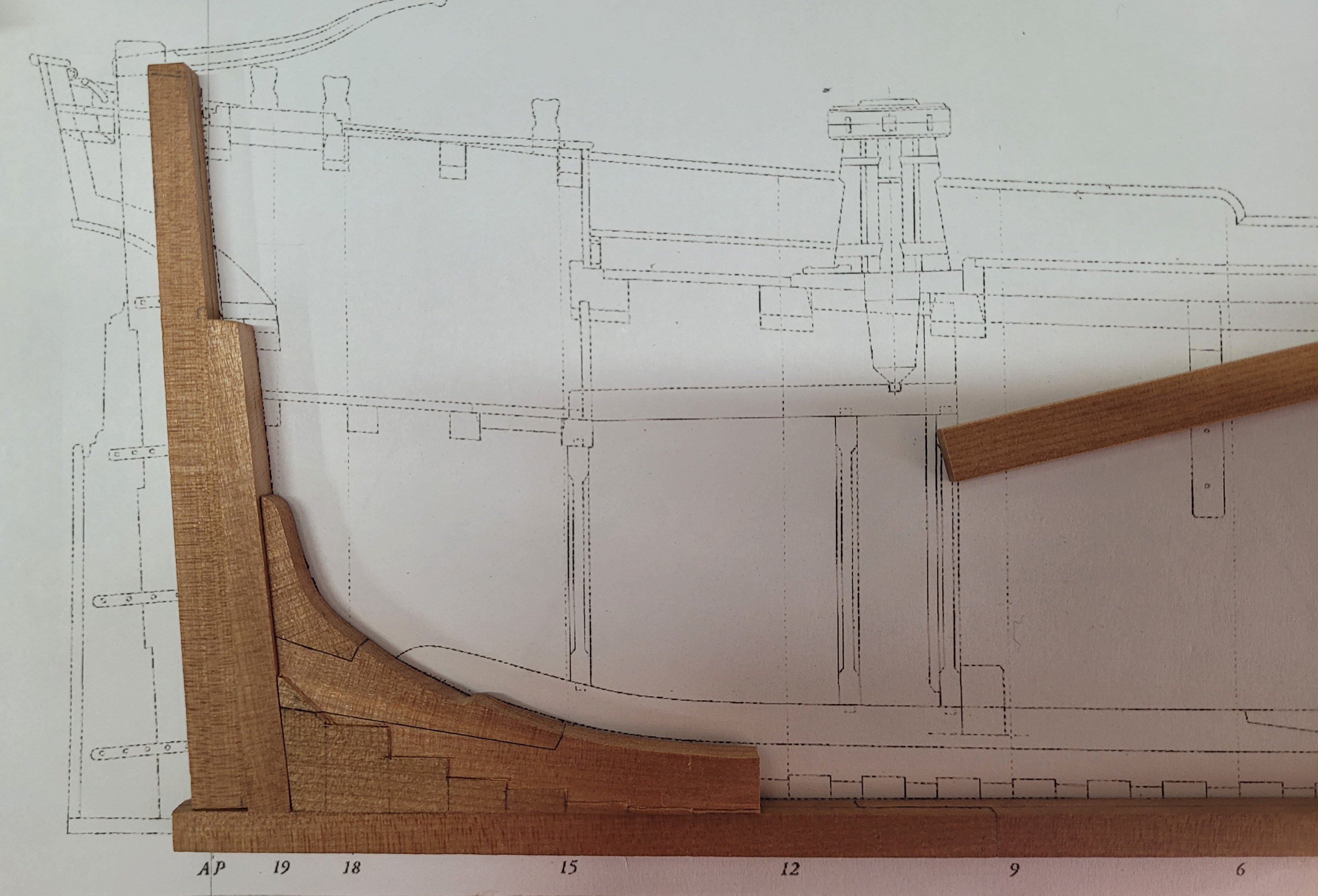
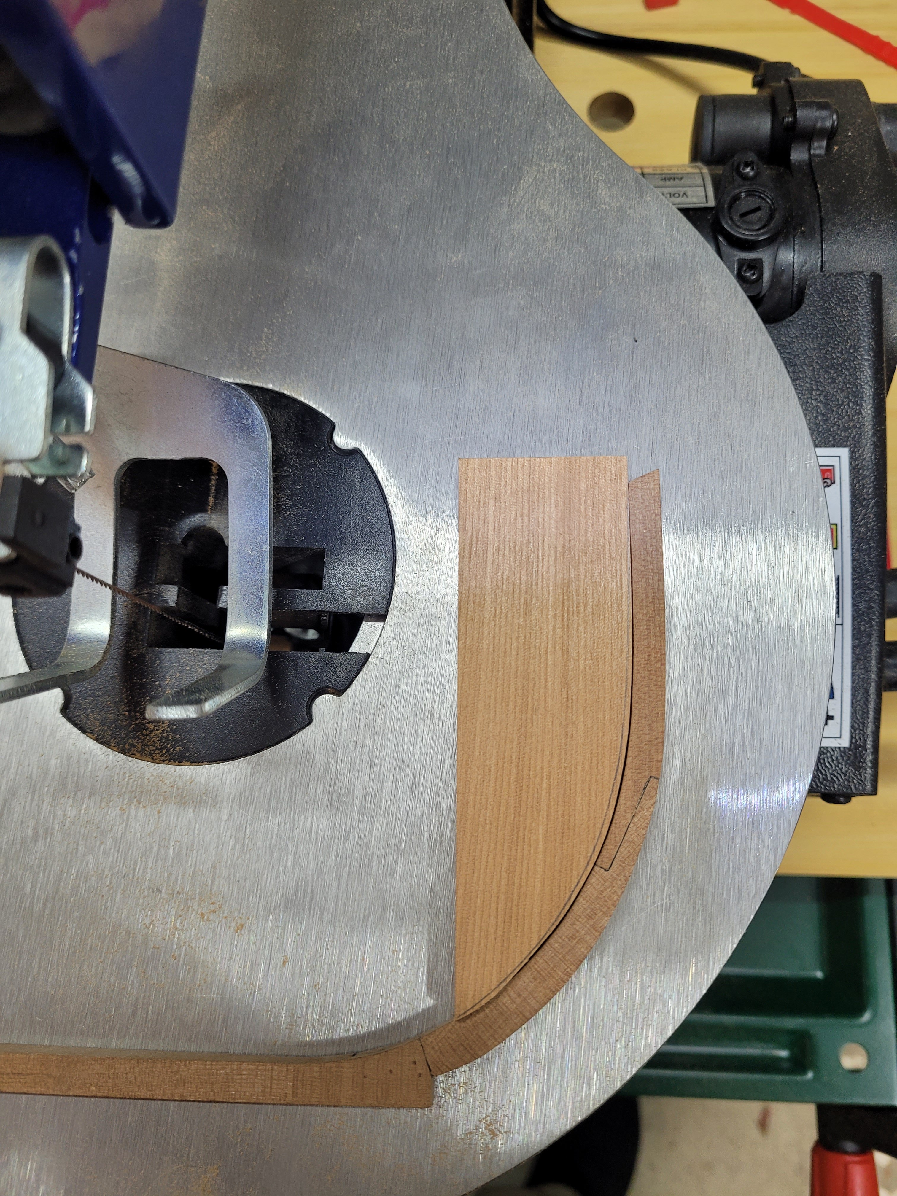
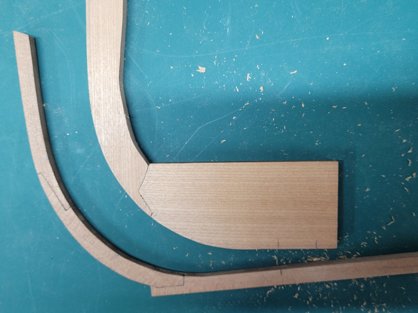
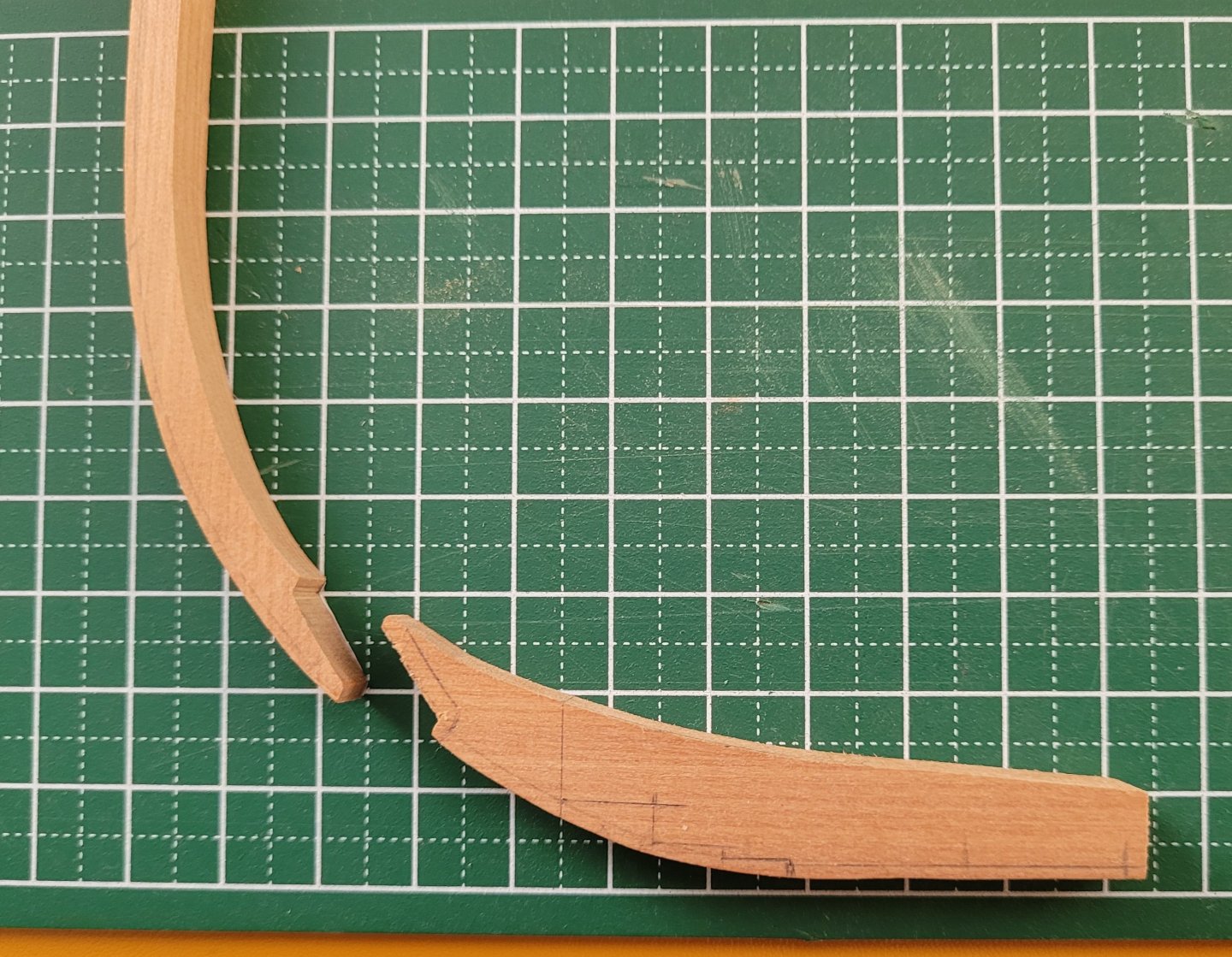
Work has continued on the stemson and the fore deadwood, and especially on trying to get a good scarph joint connecting them. I cut a couple of practise joints on some scrap wood and found a technique that seemed to work for me - basically it involved having a piece that is a little over length, making the joint a fraction further down the wood than is actually required and getting a good fit there, and then shaving off the excess so that the joint ends up where it needs to be. In effect that breaks the process into two parts - getting a good joint and then getting it where it should be, rather than trying to get a good joint in the right place on the first go. Again, I roughly cut out the required shapes of each piece from 15" stock and sanded in the curves to match the stem and keel. Once the scarph joint was finished I was then able to move onto trimming off the excess wood. I cut out templates for the stemson and fore deadwood and glued these to my pieces and then cut off the excess wood so that they were just slightly larger than needed. Some sanding on the spindle sander evened out the transition into the curve and brought the dimensions down to just a hair over size. Final sanding of the inside curves where the two pieces meet will happen when I am ready to install them - at the moment the stemson sits just proud of the fore deadwood. The deadwood was then temporarily pinned in place on the keel to help with marking out the areas that need milling to produce the stepping line. 1.5" needs to come off each side to reduce the width of the centre section from 15" to 12". Hopefully the milling will go without any problems! I won't cut out the lowest steps towards the rear of the deadwood just yet as I have found that they can be so very fragile when still working on shaping and finishing the piece - so they will be the last things I do with it before installation.
- 92 replies
-
- 13
-
-
Count me in for vol 2 Mike. (I'm already on your list) Jeremy
-
Thanks Greg, that is helpful. One of the great points about this hobby is that there are often several different methods which can be used to achieve the same ends, and it is a question of working out which one works best for you. It is a steep learning curve moving from kits to scratch building and discovering these different methods or processes and experimenting with them is proving to be very interesting.
-
Yes, that is correct. It is much easier to position the two pieces on the box and note where the high and low points of the join are than holding the two pieces together up towards the window etc.
-
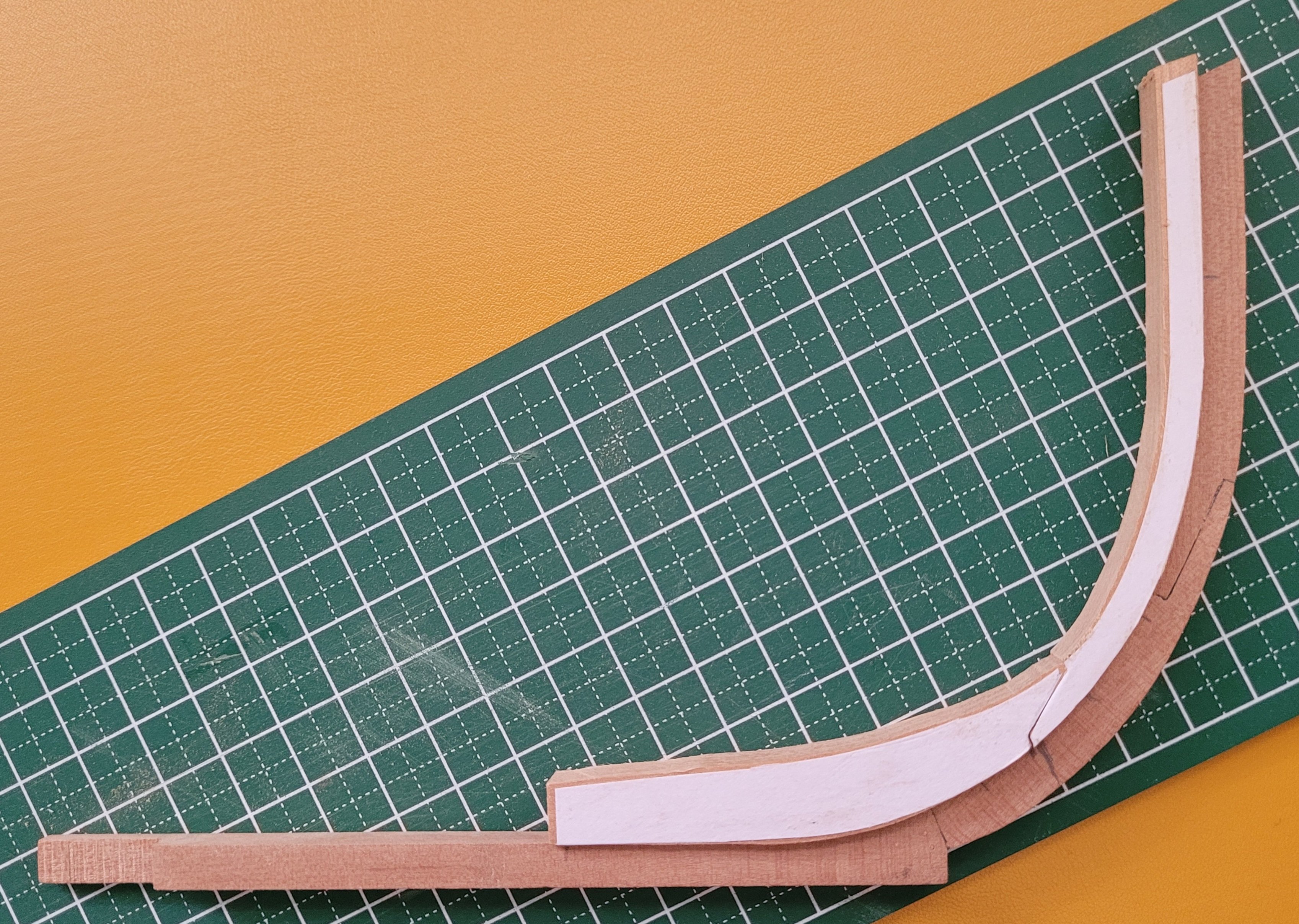
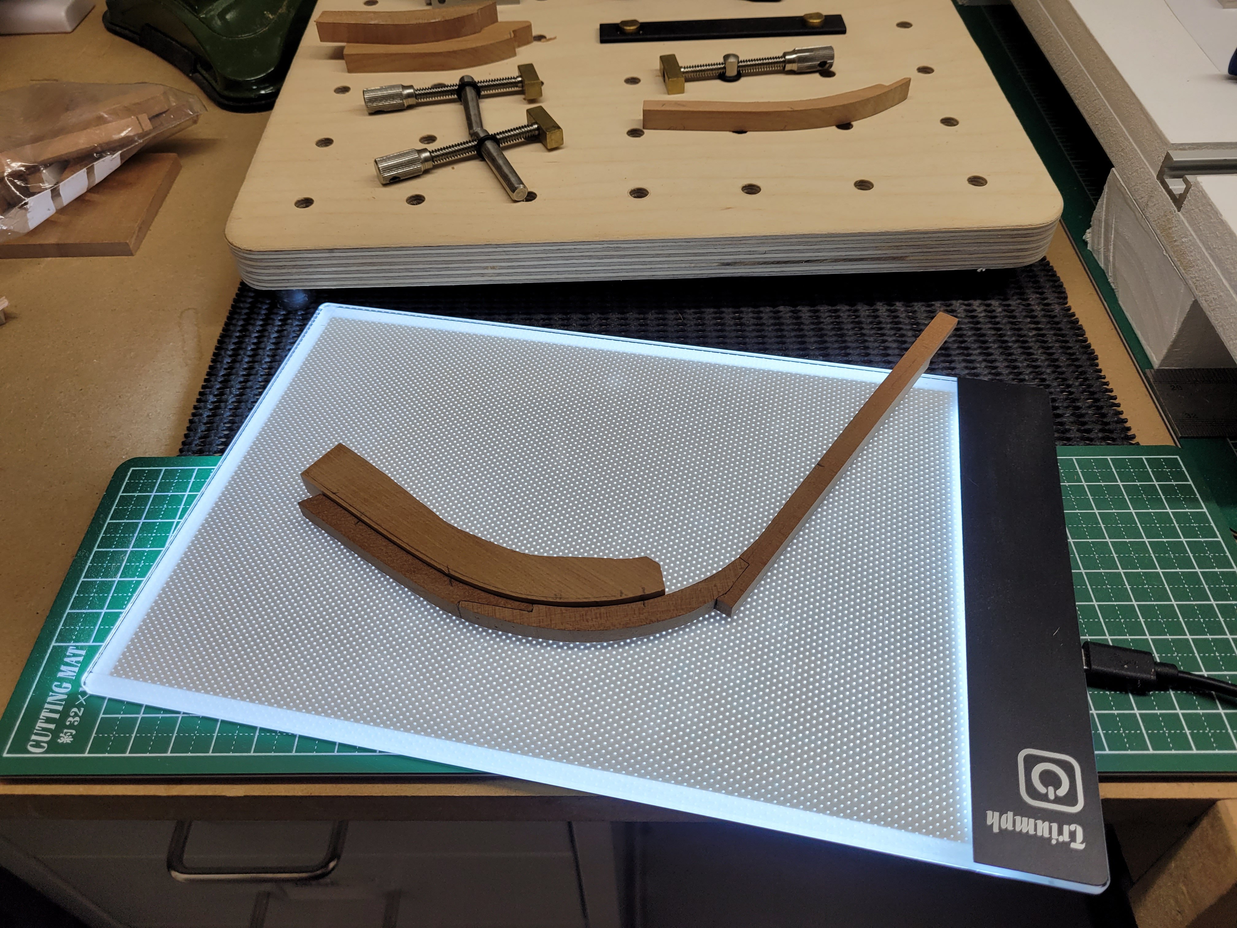
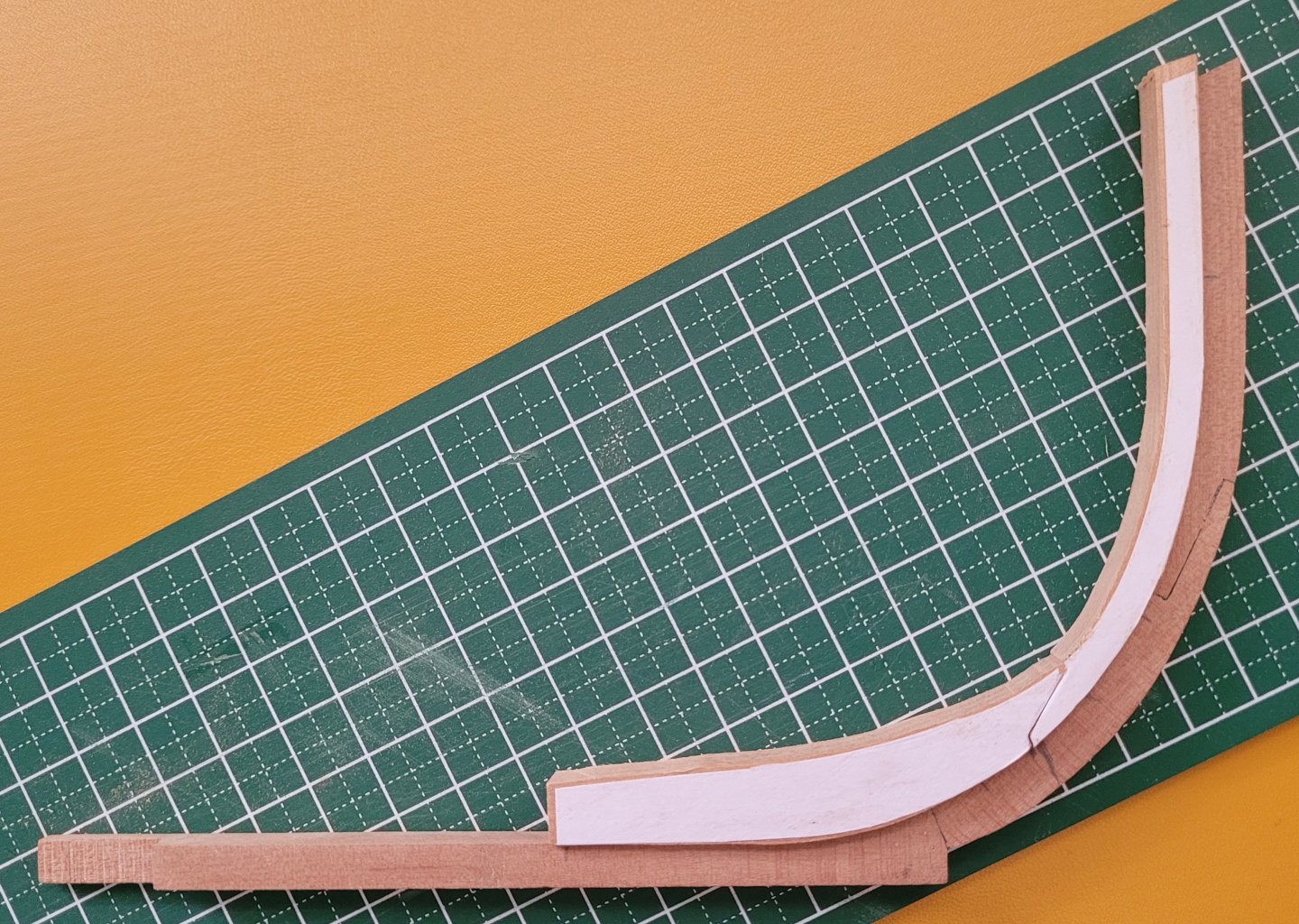
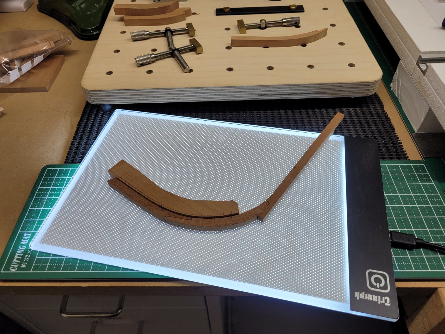
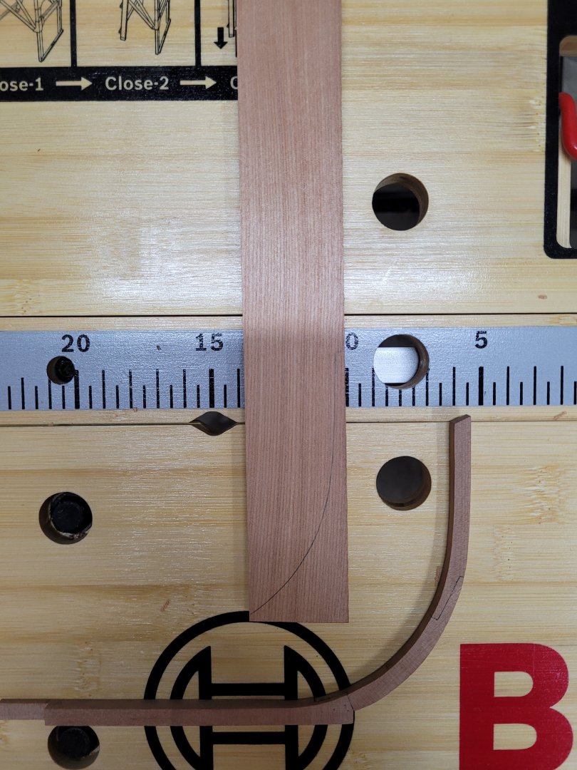
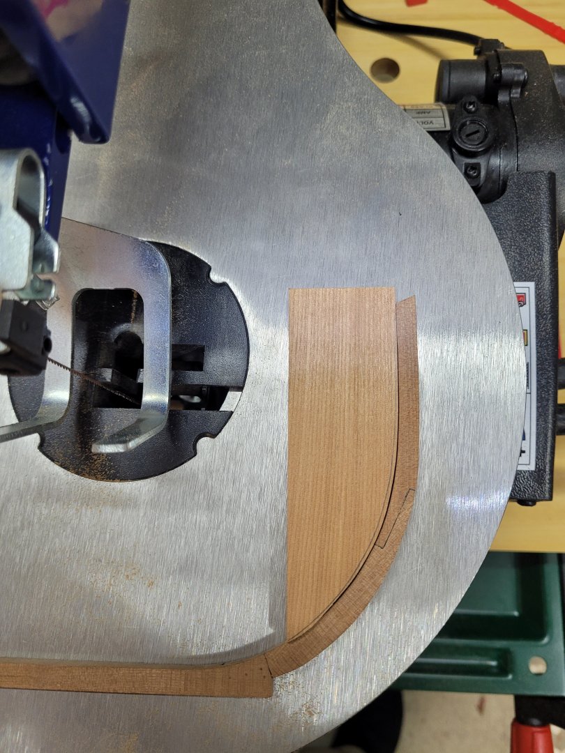
Hi all, I have been working on the build but I am afraid I can't really say that I have been progressing much in the last couple of weeks. Unfortunately, it has been a case of one step forwards and one step backwards! I started working on the stemson and the fore deadwood pieces and used my new light box to help me match the shape pf the curve of the stem to these two pieces. The light box has certainly been a useful addition to my growing list of tools and it wasn't actually that expensive so I am pleased with how that has assisted me. Unfortunately, once I had both pieces matched to the shape of the curve of the stem I then made a mess of cutting the scarph joint between them. I had a nice join on one side of the pieces but a gap in the join on the other side - clearly I hadn't cut the scarph squarely. I therefore made another set of the two pieces and paid more attention to getting the scarph cut squarely this time and i am glad to say I was successful with that part. However this time, although the scarph was cut squarely I had taken too much wood from the pieces and it wasn't an acceptable join. So I am now on my third set of stemson and fore deadwood pieces, and this time I am hoping I can get them joined properly. I think that I may practise on two or three scrap pieces of wood making some practice scarphs to make sure I am doing it properly before committing to my shaped stemson and deadwood - I really don't want to have to shape a four set of them to the curve of the stem! Despite the setbacks I must say that I am enjoying the process and learning (or trying to learn) new skills!
- 92 replies
-
- 14
-
-
Welcome !
-
Thank you all for the likes and comments. I do have a 0.3 mechanical pencil but find that I am almost constantly breaking the lead when using it. It is a fine line between having enough lead protruding and having too much - just one more tool I need to learn to use properly 😉. (The list is quite long!) I also realised today that I hadn't used any black tissue paper in the joint between the aft deadwood and the inner sternpost, so I have now rectified that.
-
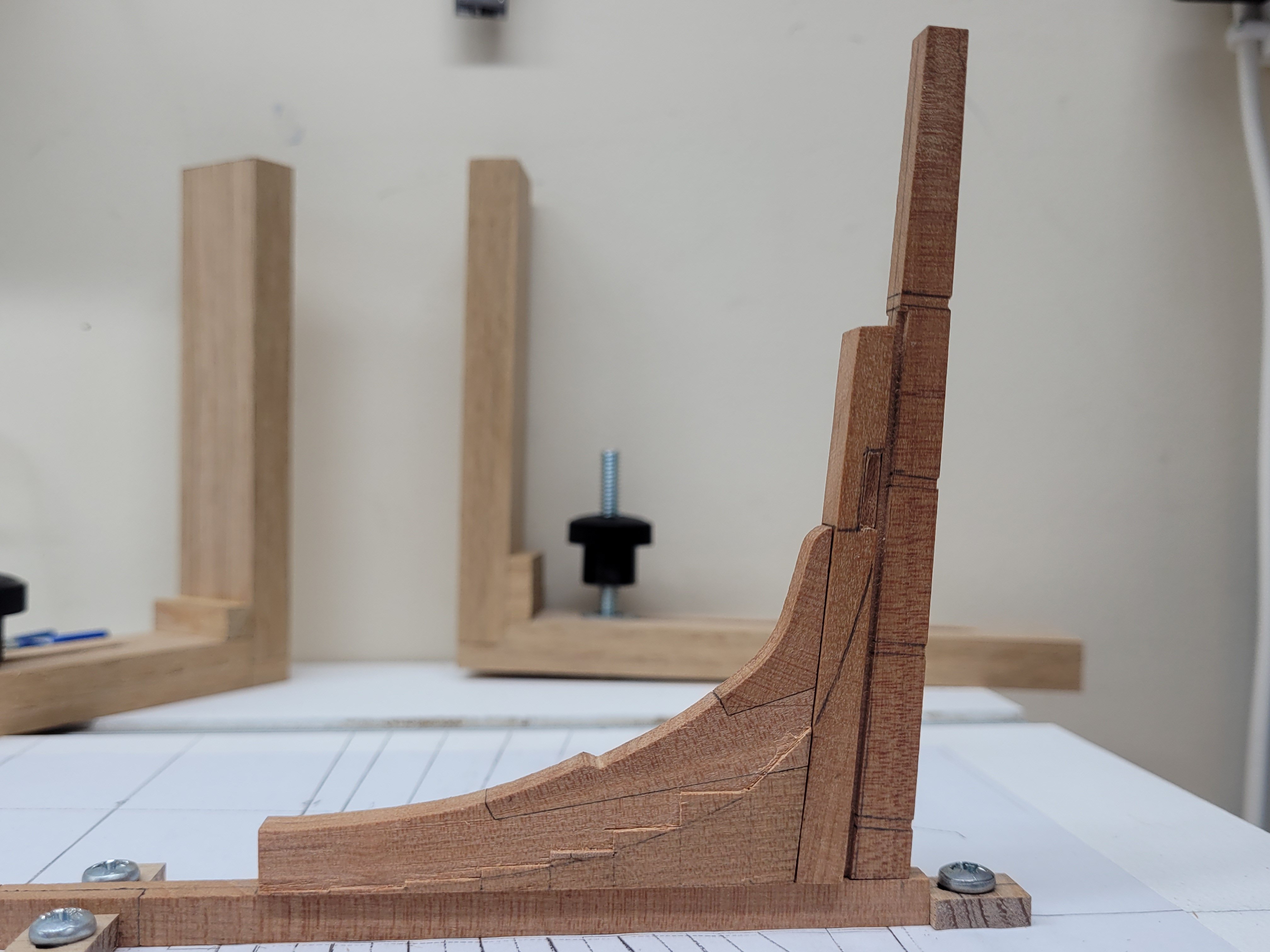
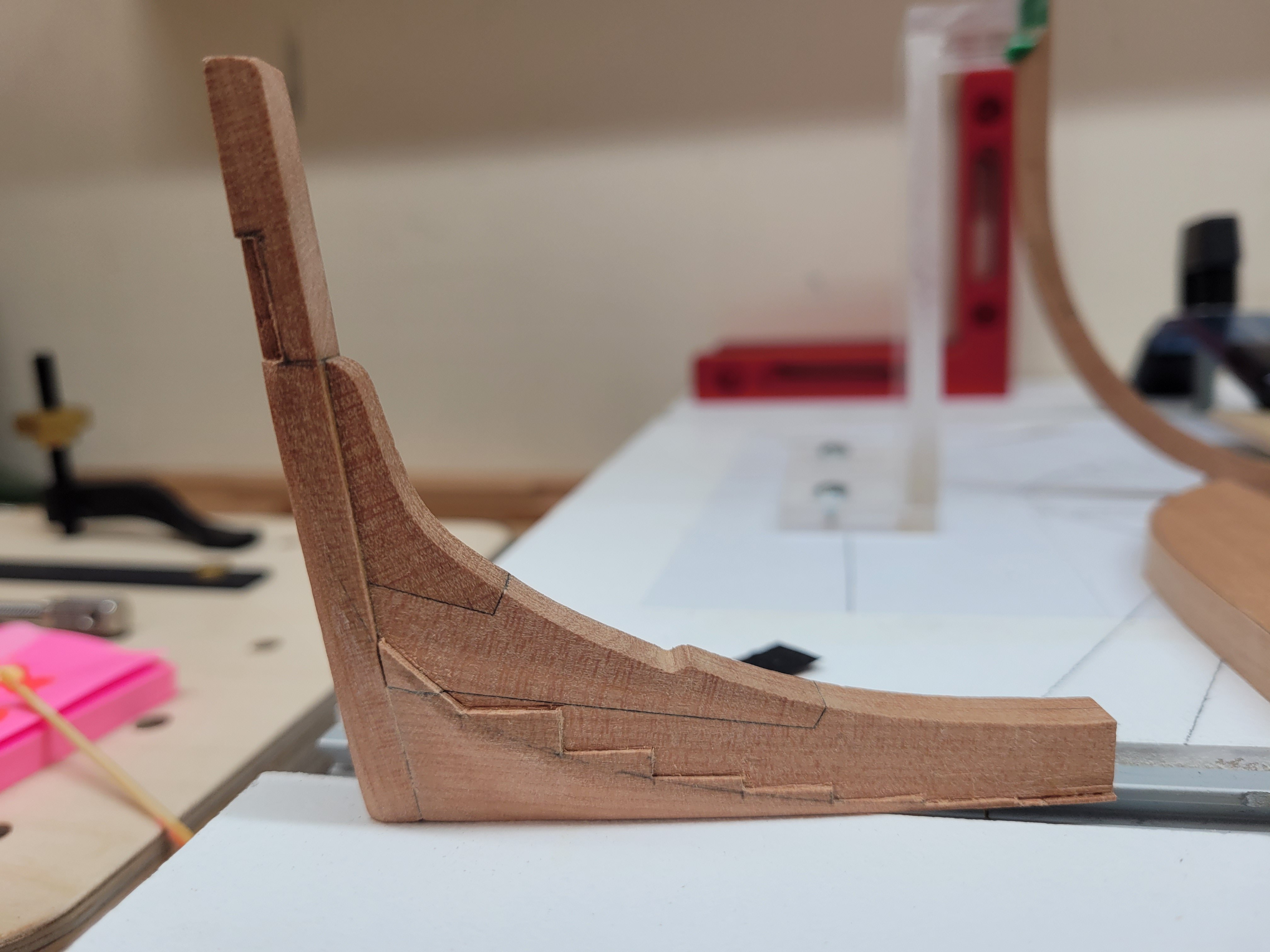
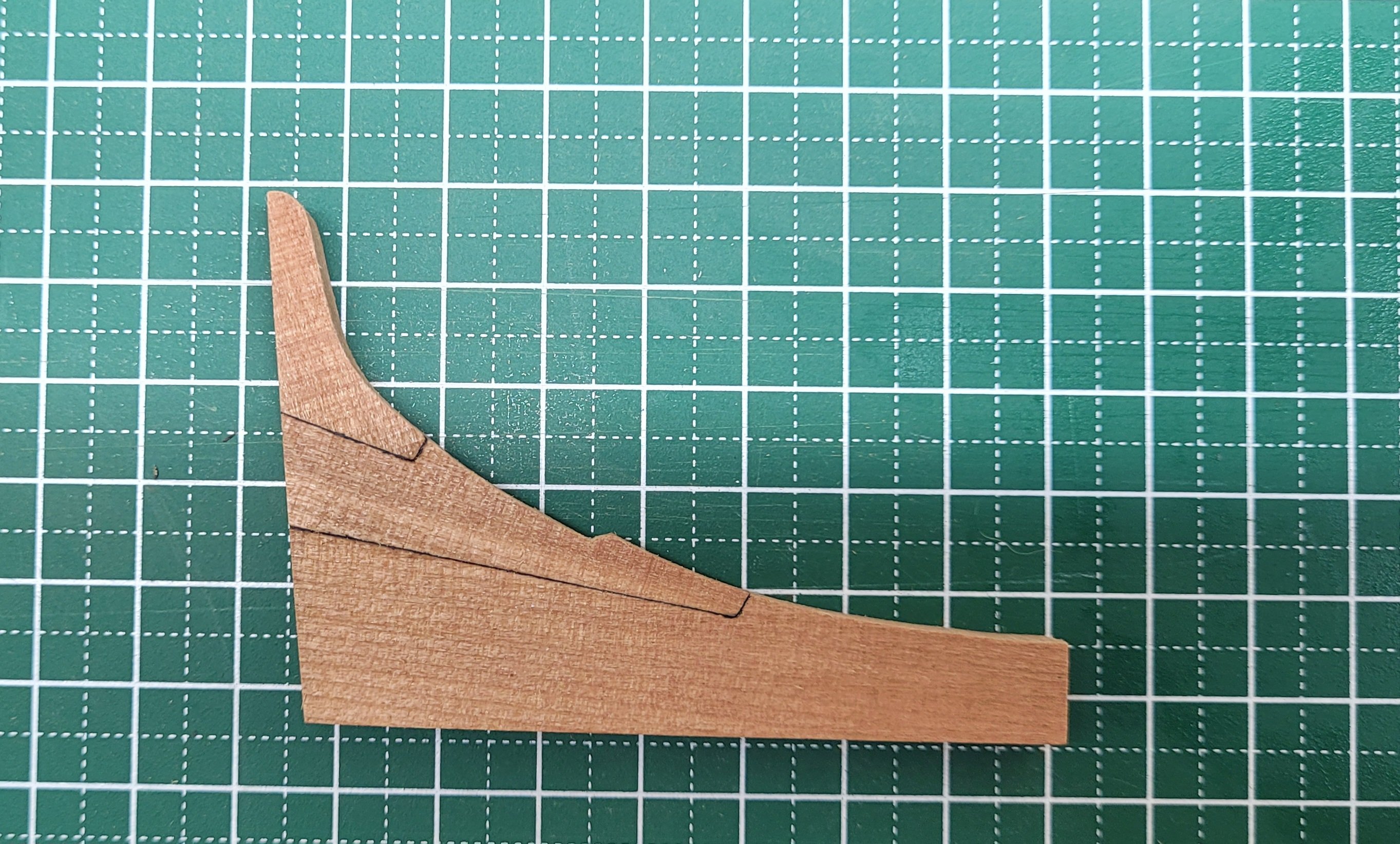
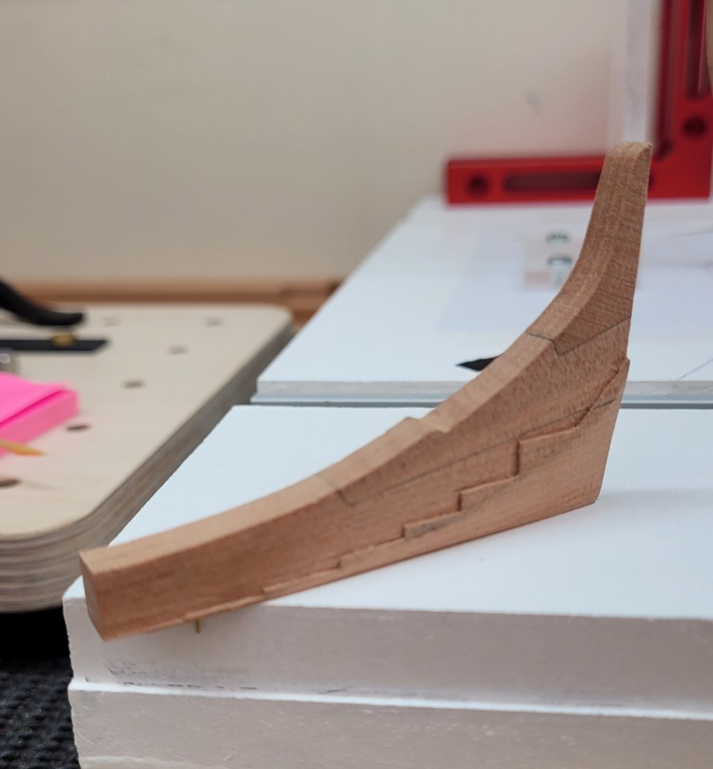
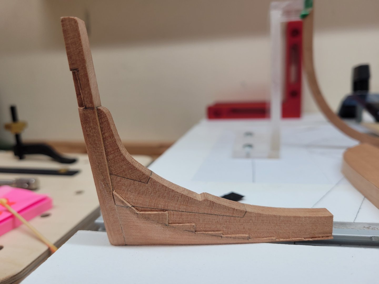
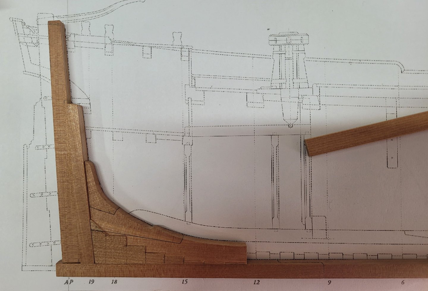
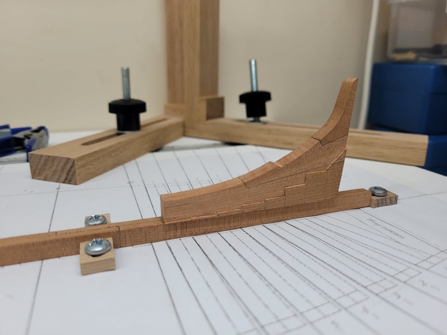
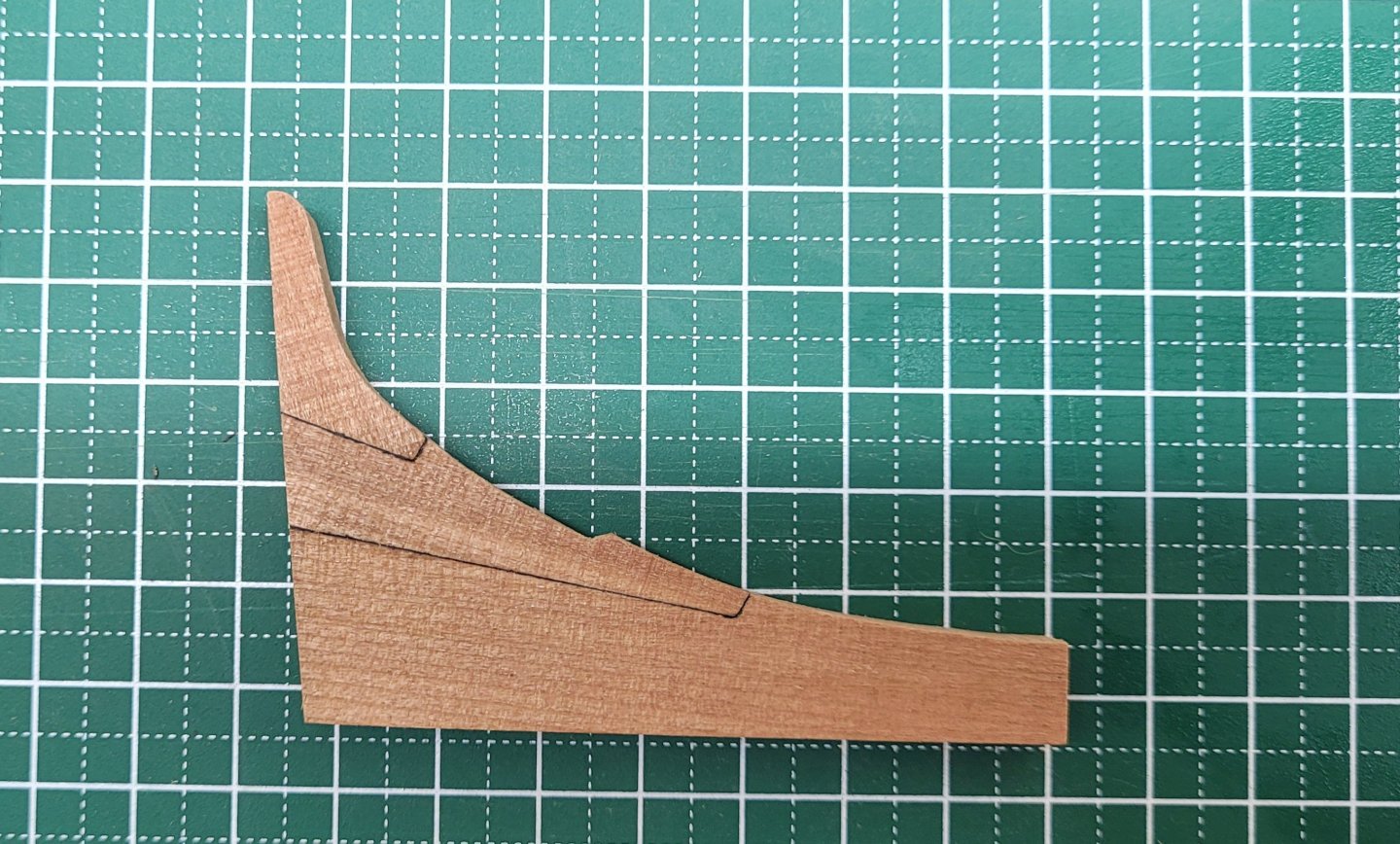
Work has been continuing on the aft deadwood, the inner stern post and the sternpost. I firstly cut out the rabbet on the sternpost using the mill. They are 3" deep. I also milled some very slight rebates on the aft side of the sternpost where the gudgeons will eventually sit. There are also two 'notches' on the inner sternpost where the ends of the fashion pieces sit but because the fashion pieces aren't the same height on both sides one notch needs to be slightly longer than the other. Here are all three pieces just sitting roughly in place on the keel. I then moved on to tidying up the steps on the aft deadwood. I realised that one step was slightly undersize on one side compared to its opposite number and so I added a small sliver of wood to build that up a little. I also made the steps nice and crisp and marked out the curve for the area under the bearding line on the base and rear sides of the aft deadwood to give me a guide when sanding this area. The initial sanding was done with a dremel sanding band initially and then I moved on to a variety of curved sanding shapes using 240# grit paper. I didn't sand all the way down to the final shape at this time as I thought it would be easier to achieve the desired curve once the inner sternpost was attached to the deadwood. I started some initial sanding on the inner sternpost before gluing and pinning both pieces together. Further sanding then helped to blend the curve across the two pieces. It was at this point that I realised that during the sanding process I had somehow managed to break off parts of the foremost step on each side of the deadwood. As mentioned previously these are very small and delicate pieces and I should have no doubt taken more care with them! I decided that a repair could be effected by cutting out a small section of the base of the deadwood on both sides and gluing two thin pieces of wood there extending out to each side. These were then cut to size to represent those two foremost steps. I think if I was to make the deadwood again I would refrain from milling in these foremost steps until the rest of the shaping of the piece had been completed, thereby avoiding the danger of damaging them. I was also slightly over zealous in sanding one side of the inner sternpost - it ended up a bit thinner on one side when compared to the depth of the rabbet on the sternpost. I don't believe this will be an issue later on as further sanding will be required when fairing the frames, but I have not yet attached the sternpost to the inner sternpost just in case I decide to change it. Finally at this stage I cut out a piece of 15" wide wood for the rising wood. This was made in two pieces with a scarph joint and the positions of the main station lines were marked on it.


- 92 replies
-
- 18
-
-
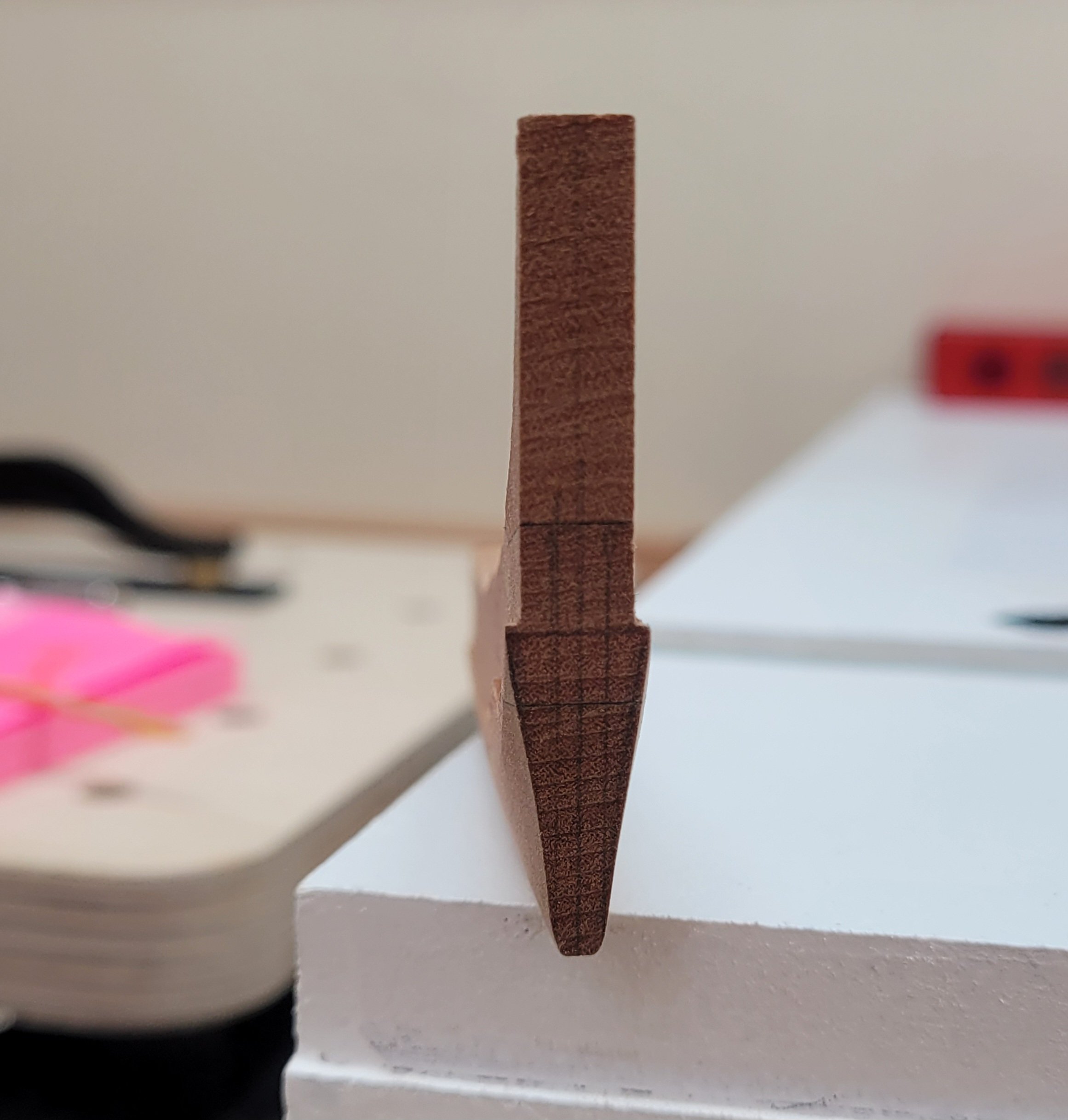
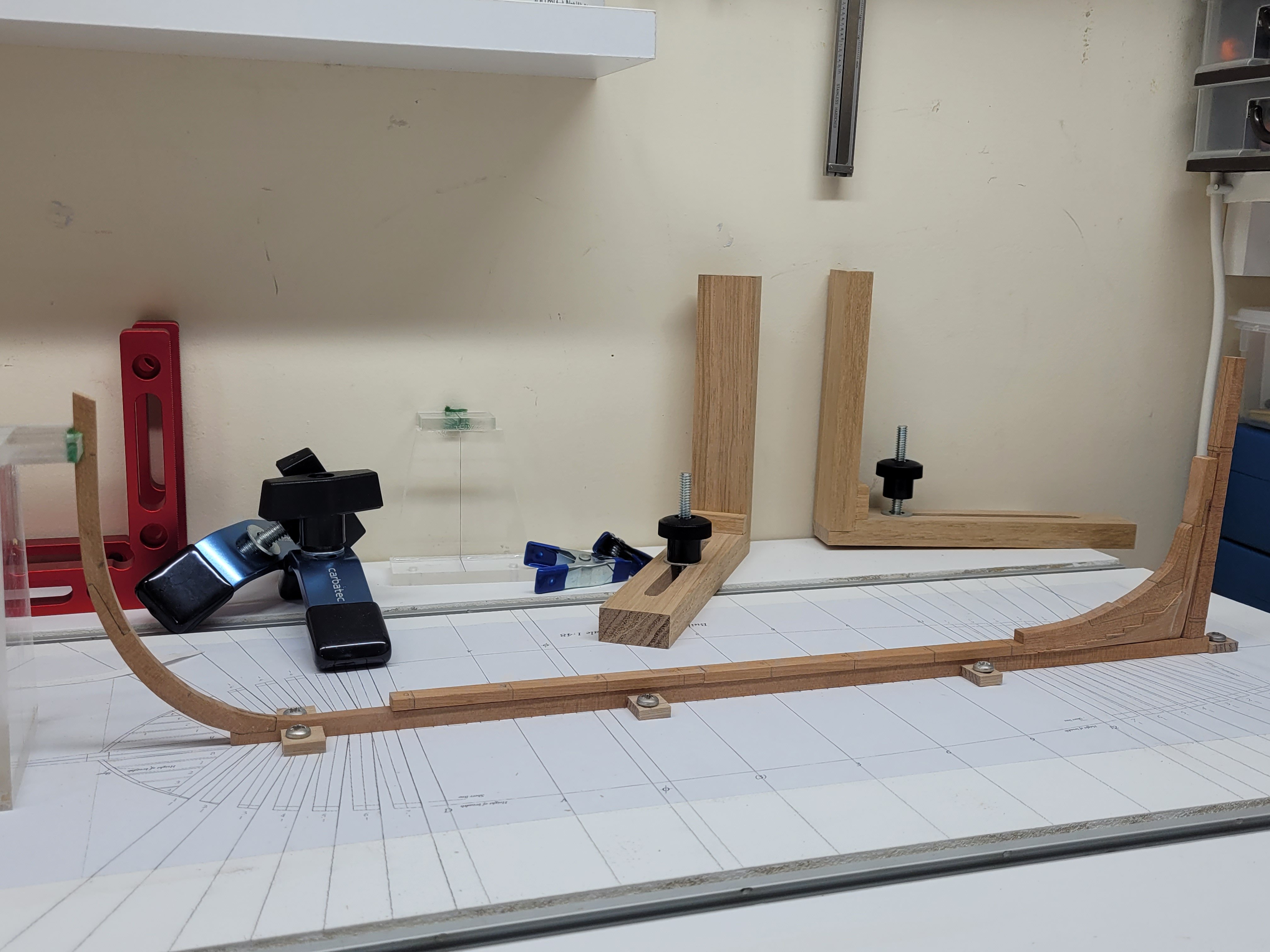
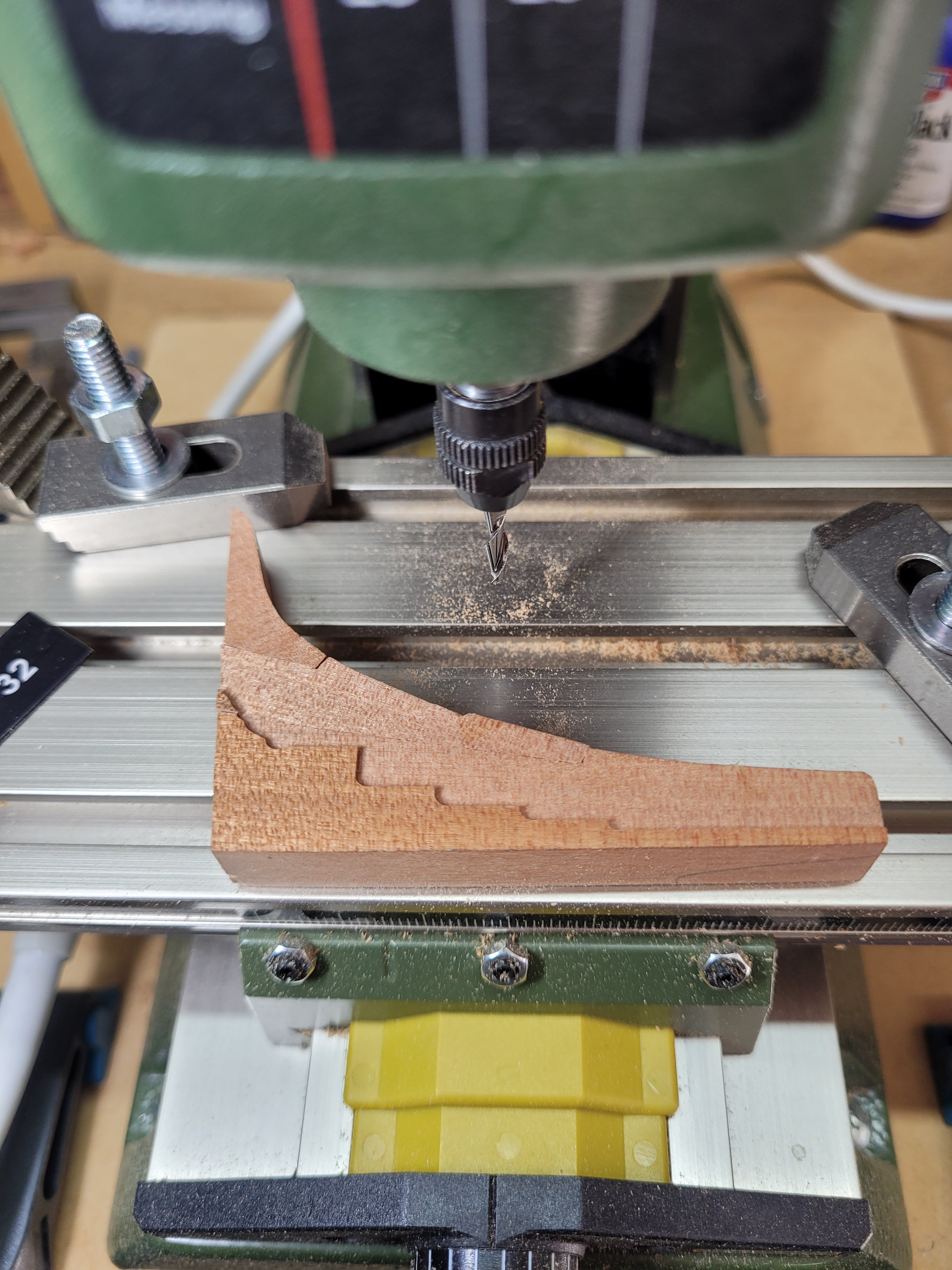
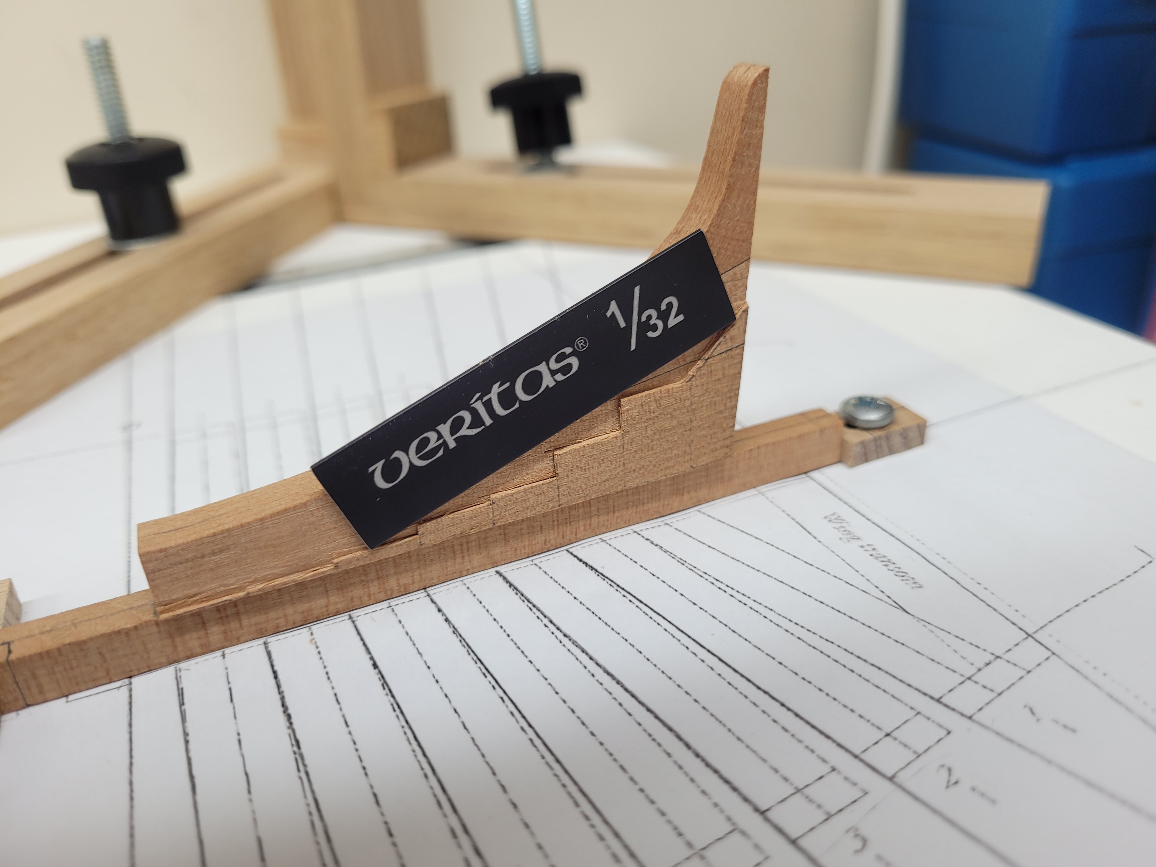
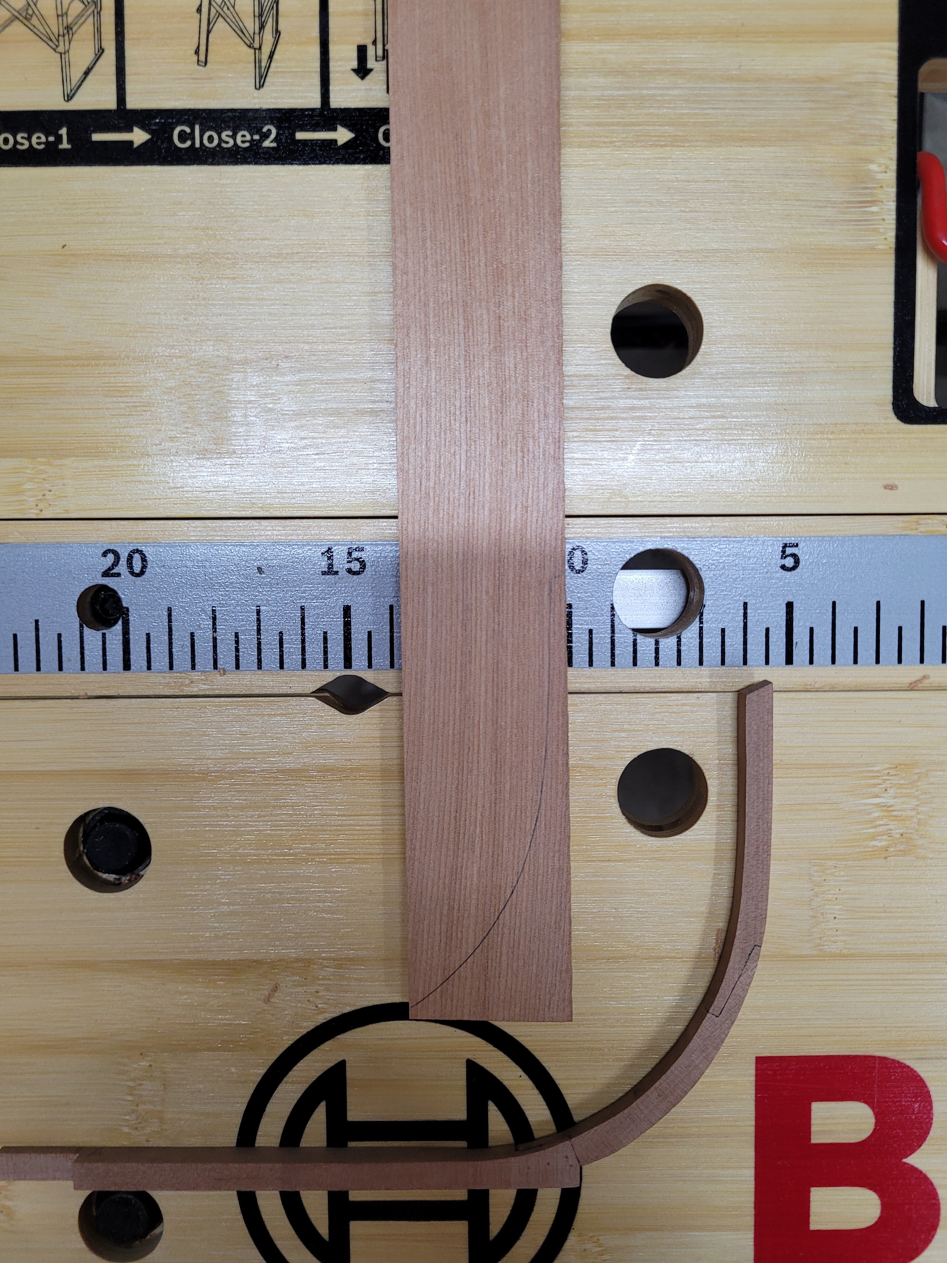
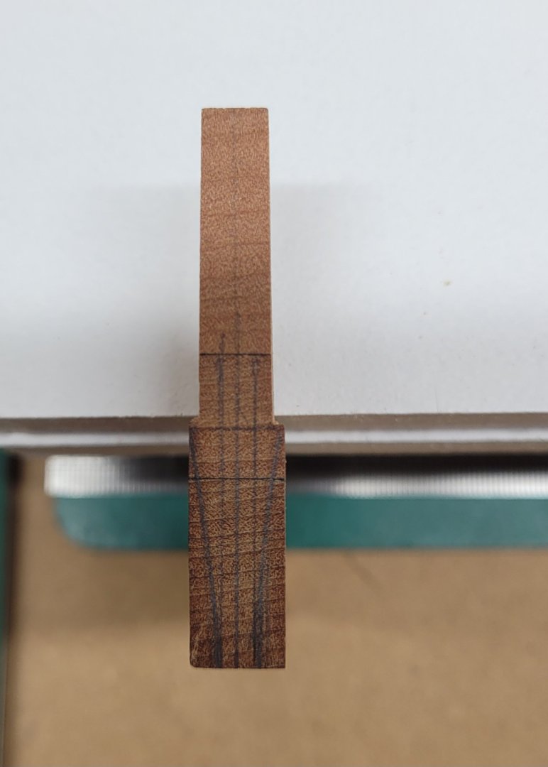
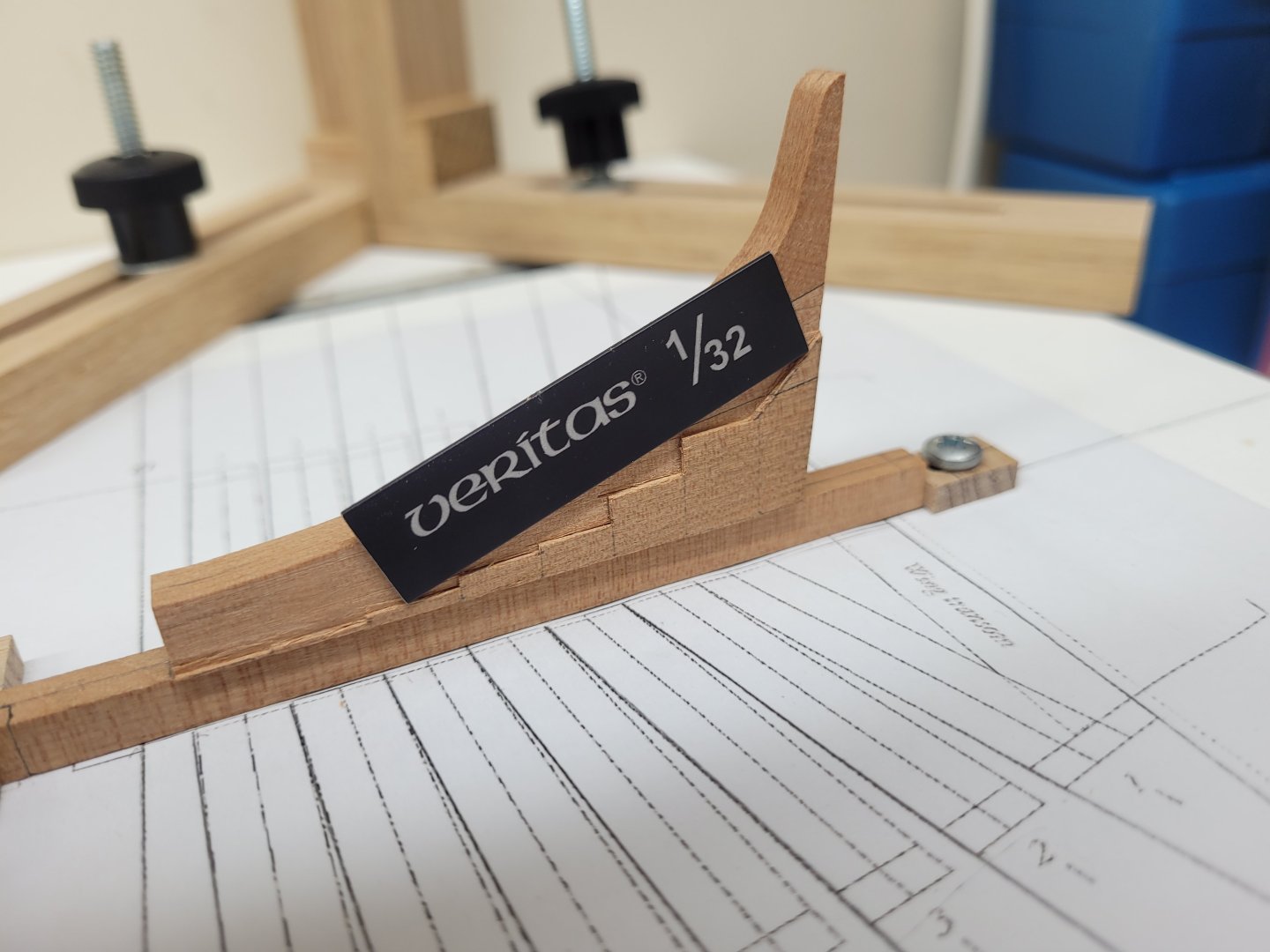
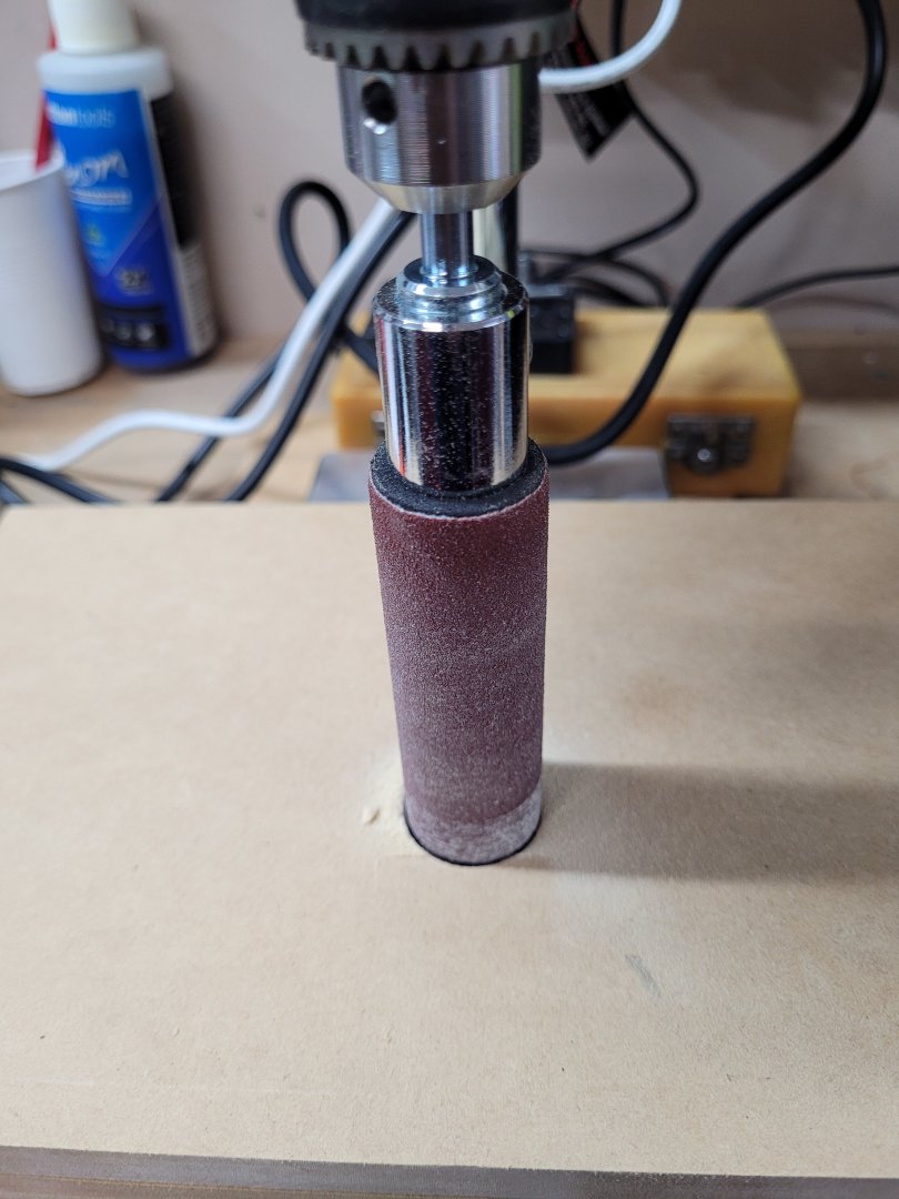
I moved on to work on the milling of the stepping line in the aft deadwood. I didn't want to ruin the deadwood piece on my first attempt so I quickly glued up a second iteration of the deadwood from some spare offcuts - it isn't quite the correct size or thickness but it did serve a purpose of letting me have a piece with which I could work out the best way to approach the task of milling in the steps. I used my mini Proxxon mill for this and was pretty pleased with my first attempt. Here it is with most of the steps milled in (or out?). This gave me the confidence to try the same procedure on the proper aft deadwood assembly. Before I started the milling though I firstly drilled a couple of holes in the centre of the keel and the centre of the underneath of the aft deadwood so that it could later be pinned in place - this ensured that it sits centrally on the keel in the same position. The dept of the milled area is 1/32", thereby reducing the 15" scale size timbers to 12" when repeated on both sides. The foremost step is so very very thin, much less than 1/32" high, and I was worried about the wood splitting there so I made sure to have a backing piece against it to avoid that. Here is the aftdeadwood pinned in place on the keel. I need to do a bit more tidying up of the steps and the start of the curve of the bearding line with my chisels. I have a Veritas set up block set which includes pieces down to 1/32" and I have found these to be really handy for measuring depths or heights, and for use as shims on tapered pieces - for example if you need to cut a perpendicular edge on a tapered piece of wood. Above is the 1/32" piece showing the depth of the milled steps. I have an also cut the sternpost and the inner stern post to size. Below is a mock up of the stern pieces all together on the keel. There is a lot more work that needs to be done on them yet though, including cutting out the rabbet, marking the bearding line and sanding the area below it before I can install any of them permanently to the keel. I have also cut out two lengths of 15" wide timber which will form the rising wood in due course, you can just see one of those to the top right of the picture above.

- 92 replies
-
- 13
-
-
Thanks Greg. I used a Blustick which sounds similar to your method. Perhaps it was something in that particular type of tracing paper that caused the problem. I certainly haven't noticed the same thing happening with paper templates when the same Blustick was used. The sanding drums can be fitted with any grade of paper which is very helpful as I can swap between grades depending upon the work required.
-
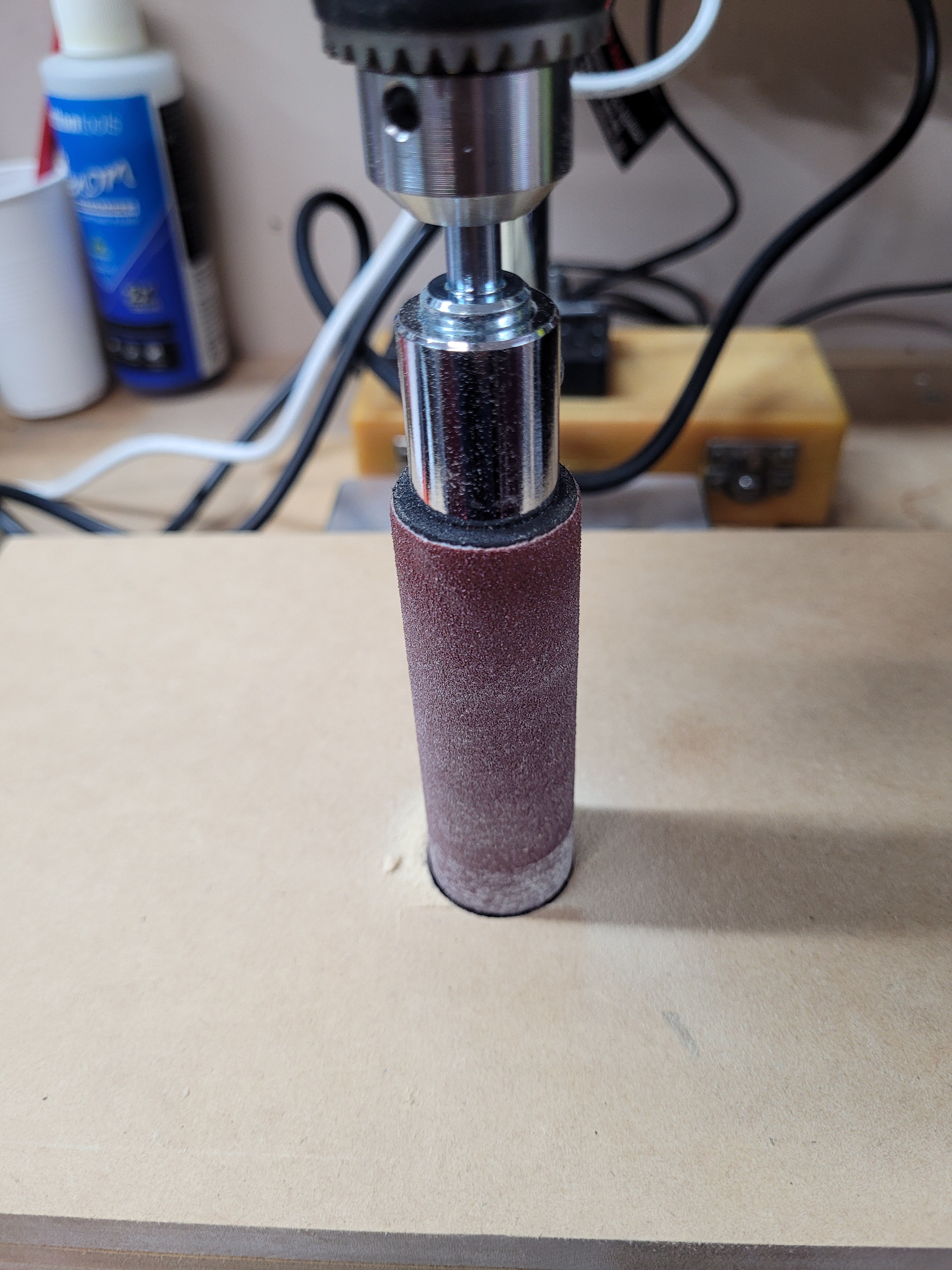
It has been a while since I last posted any update - and to be honest I haven't had a lot of time to devote to modelling in the last few weeks. What time I have had has mostly been spent either reorganising tools and workspaces or taking just a few steps forward and then a few steps backwards with the build! I thought it would be a good idea to get a proper spindle sander setup and as space doesn't allow me to have a dedicated spindle sander I instead purchased some sleeveless sanding drums to use in the drill press. The sleeves are 1 inch, 2 inch 2.5 inch and 3 inch in diameter. I made a little spindle sanding station so that there was a nice flat baseboard on which to place the pieces when they are being sanded - here is the 1 inch drum in the press. I have made and then subsequently discard two attempts at making the stemson. The stemson is made from 15" stock and in each case I found it difficult to get the join between it and the stem nice and uniform. I am now on my third attempt and rather than using a cut out template from the plans I have this time traced the shape of the inner curve of my stem onto the piece of wood. This has then been cut out on the scroll saw and now needs sanding to ensure a snug fit. I have purchased a cheap A5 lightboard to help me with checking the fit of the joint and hopefully that will help me improve on my earlier less successful attempts! One useful piece of knowledge I have recently acquired is that it isn't a good idea to use tracing paper as a template for any of the pieces. I had traced the shapes of the aft deadwood pieces on tracing paper and then glued then to some 15" stock but when I came to cut them out on the scroll saw I noticed that the act of gluing the tracing paper to the wood had actually resulted in the tracing paper becoming stretched in one dimension. Luckily this meant that my templates were too long rather than too short and so the pieces were still useable, but at least now I know not to do that again! I have glued the three aft deadwood pieces together with black tissue paper in the joints. The top curve of the assembled pieces have been sanded to the correct shape but the base and the rear line of the aft deadwood is still a little oversize. I will sand those to size once I have milled in the shape of the stepping line. I also need to drill holes in the base of the aft deadwood so that it can be pinned to the centreline of the keel at some point in the future.
- 92 replies
-
- 14
-
-
Looking very nice. I too had the metal anchors and struggled with getting them painted. Lots of touch ups were needed during and after mounting them.
- 562 replies
-
- 3
-
-
-
- vanguard models
- alert
- (and 2 more)
-
This looks like an interesting build Harry. I also like those decals ! Thanks for the details about where you got them from.
- 186 replies
-
- 2
-
-
- Flying Cloud
- Mamoli
- (and 1 more)
-
That's a good tactic! I might have to try that out myself. 😀
-
Many thanks Druxey! That is very helpful. It is a much simple solution than I had imagined. I was obviously over complicating it due to not understanding the various lines representing the shape of the transom, so thanks also for pointing out how they represent the curved nature of that piece.