HOLIDAY DONATION DRIVE - SUPPORT MSW - DO YOUR PART TO KEEP THIS GREAT FORUM GOING! (Only 20 donations so far - C'mon guys!)
×

jpalmer1970
-
Posts
408 -
Joined
-
Last visited
Content Type
Profiles
Forums
Gallery
Events
Everything posted by jpalmer1970
-
 Hi, There is a set of these for sale on EBay at https://www.ebay.com.au/itm/405254327288? if you are still looking for copies. Best to check they include the CDs and plans etc. Not cheap though....
 -
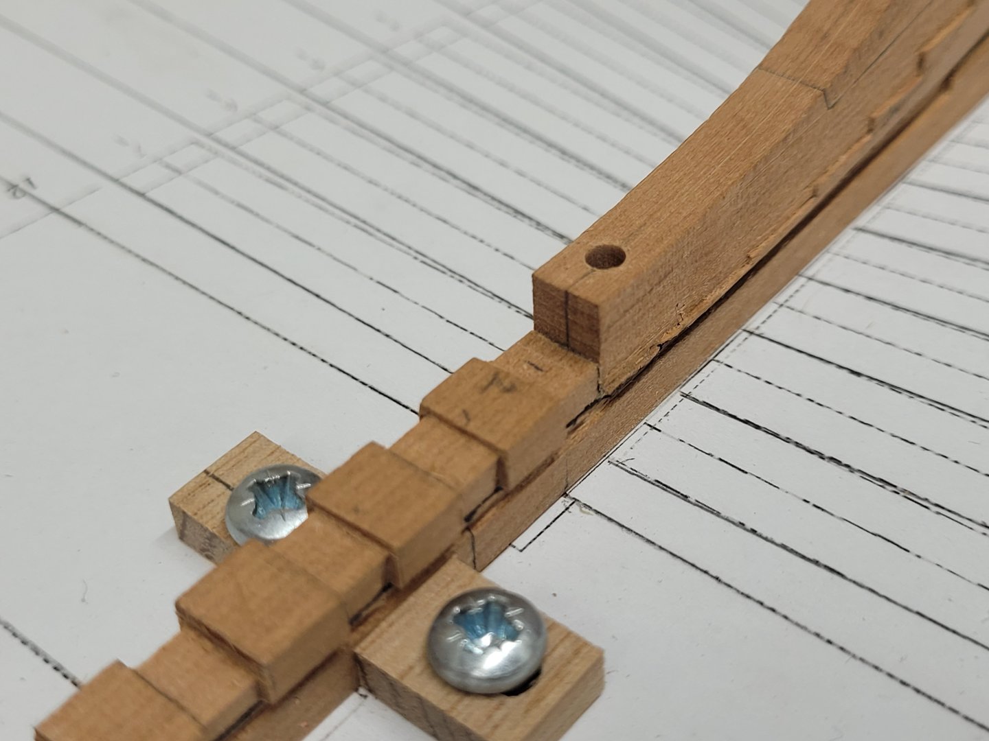
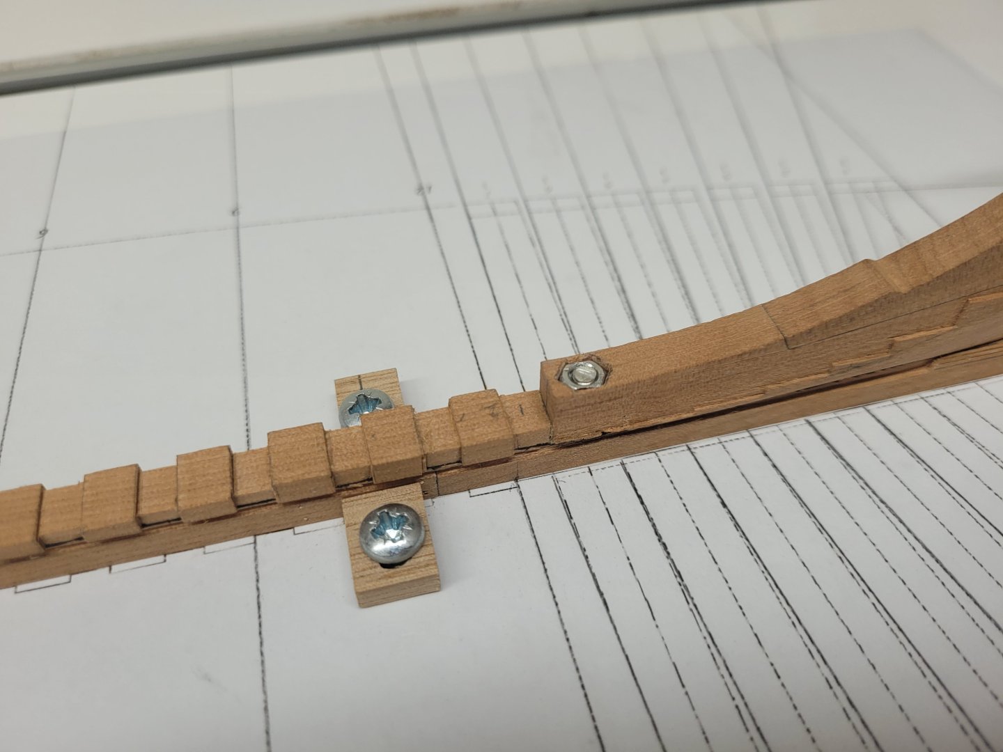
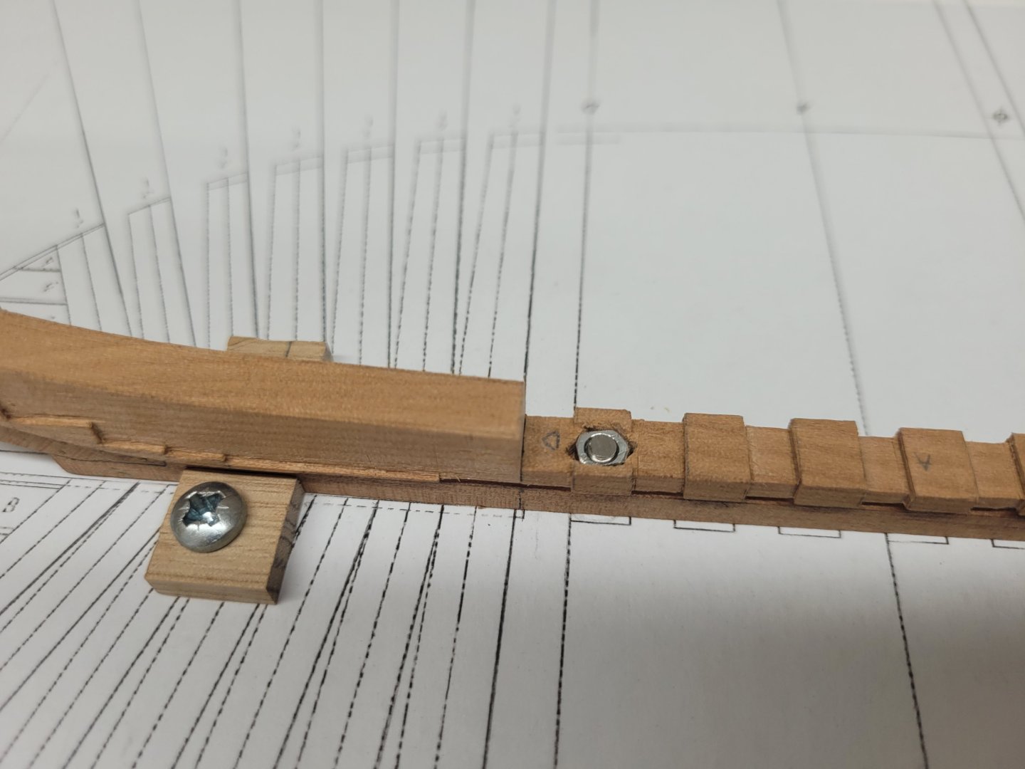
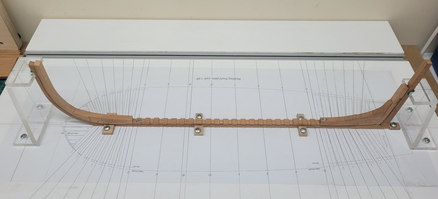
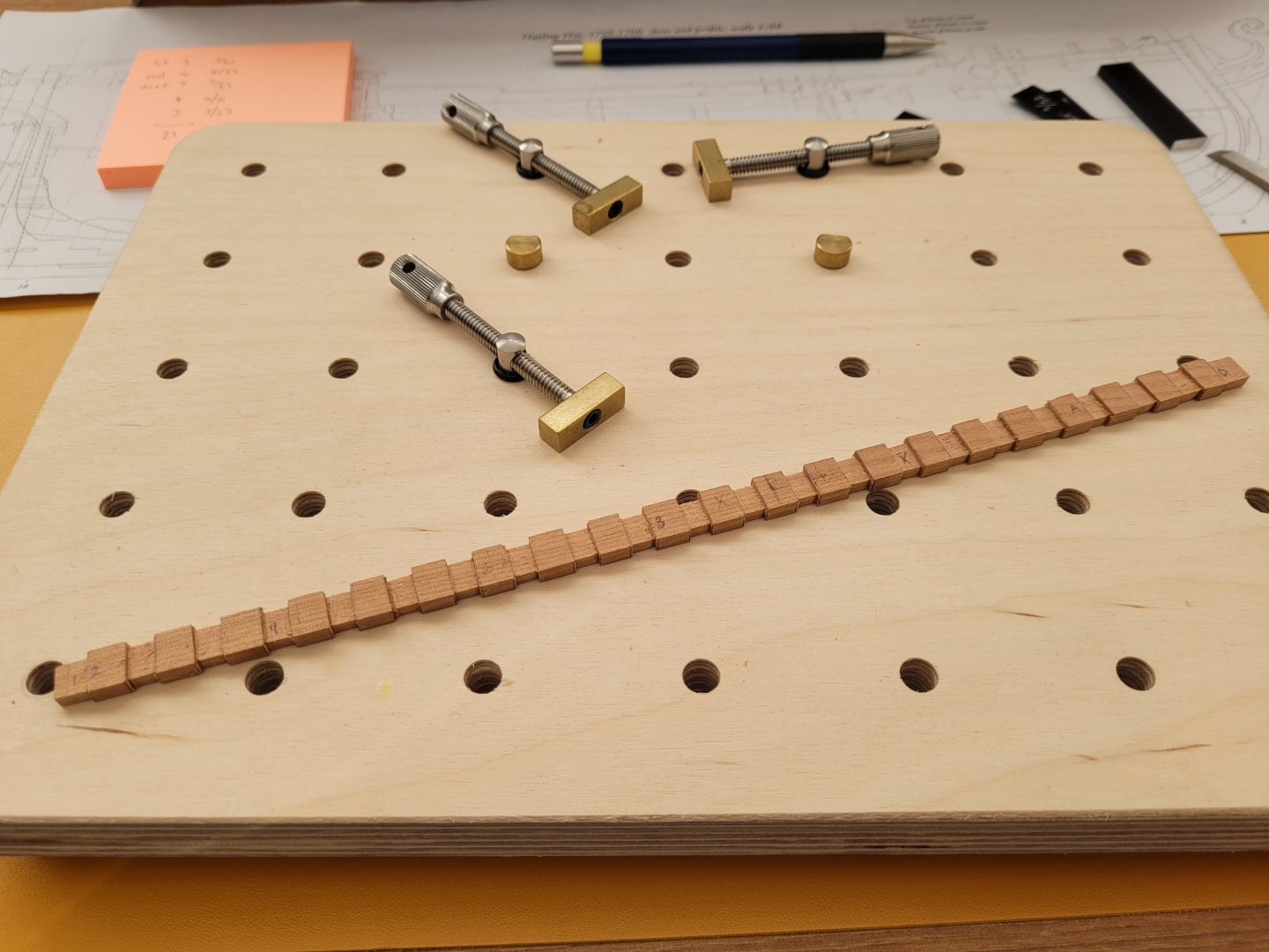
Only a small amount of progress since the last update but I have reached a mini milestone and wanted to document that. Work continued with the positioning and drilling of the pedestal bolts through the keel. I spent a while working out where the best positions seemed to be and decided on two locations the same distance ahead of the sternpost and aft of the stem. These worked out to be at the fore end of the aft deadwood and on the first part of the rising wood. I initially drilled a 1.2mm pilot hole in each location with the drill press and then moved up to a larger 3mm hole. I have some 3mm threaded rod which I am going to use as the bolts to hold the keel to the building board. With the keel clamped in place on the building board I was then able to mark out where the 3mm holes were placed so that I could then drill through these straight through the building board. I needed to fit some 3mm nuts in the aft deadwood and the rising wood but before starting on that I firstly ground down the opposite sides of the nuts a little to make them slimmer so that they didn't sit too close to the edge of the keel. To make cutting these recesses for the nuts a little easier I drilled out a 4mm wide area just slightly deeper than the nut thickness, and then I used the chisels to cut out the remainder of the hexagonal shape of the nuts. I then cut my 3mm threaded rod to length and inserted these through the keel and building board. The tops of the rods are held in place with the recessed nuts in the deadwood and the rising wood whilst underneath the board I have attached some wingnuts to clamp the keel tightly to the board. I still have to epoxy the recessed nuts in place at some point in the near future but this doesn't necessarily need to be done just yet. The reason why this is a mini milestone for me is that I have now reached the point in the build where David's book starts to document the build. The first picture in The Haying Hoy shows David's backbone of the ship in place and bolted to the building board and after six and half months I have now reached that point. There are 365 build step photos in the book so I still have a fair way to go..... but at least i have made it to photo 1 ! 😀
- 92 replies
-
- 20
-

-

-
Excellent work, she looks splendid! I am sure you will be glad you went the extra mile with the reef points when you look back on this build in the future.
-
Have fun, the Vanguard Models are excellent.
-
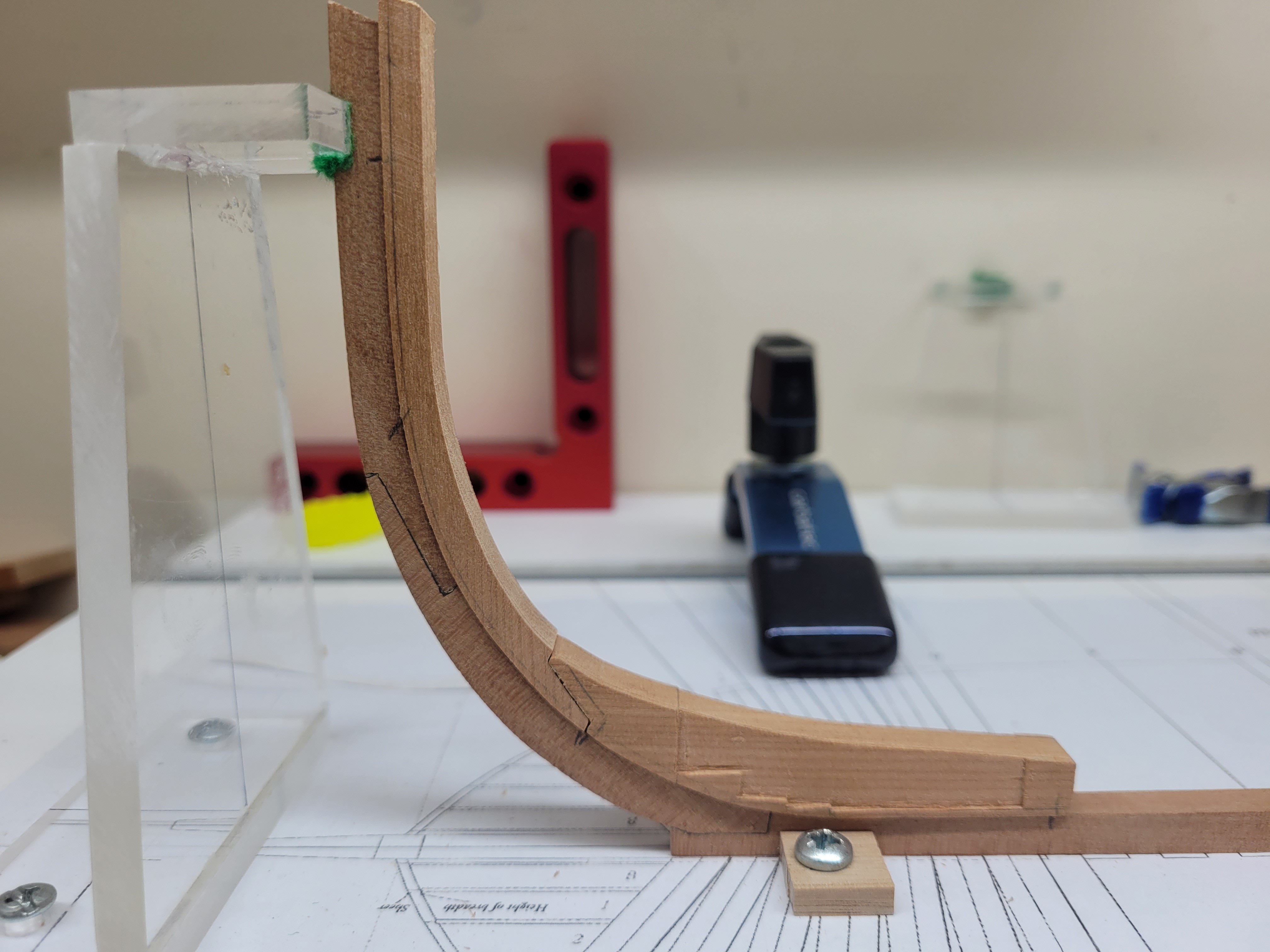
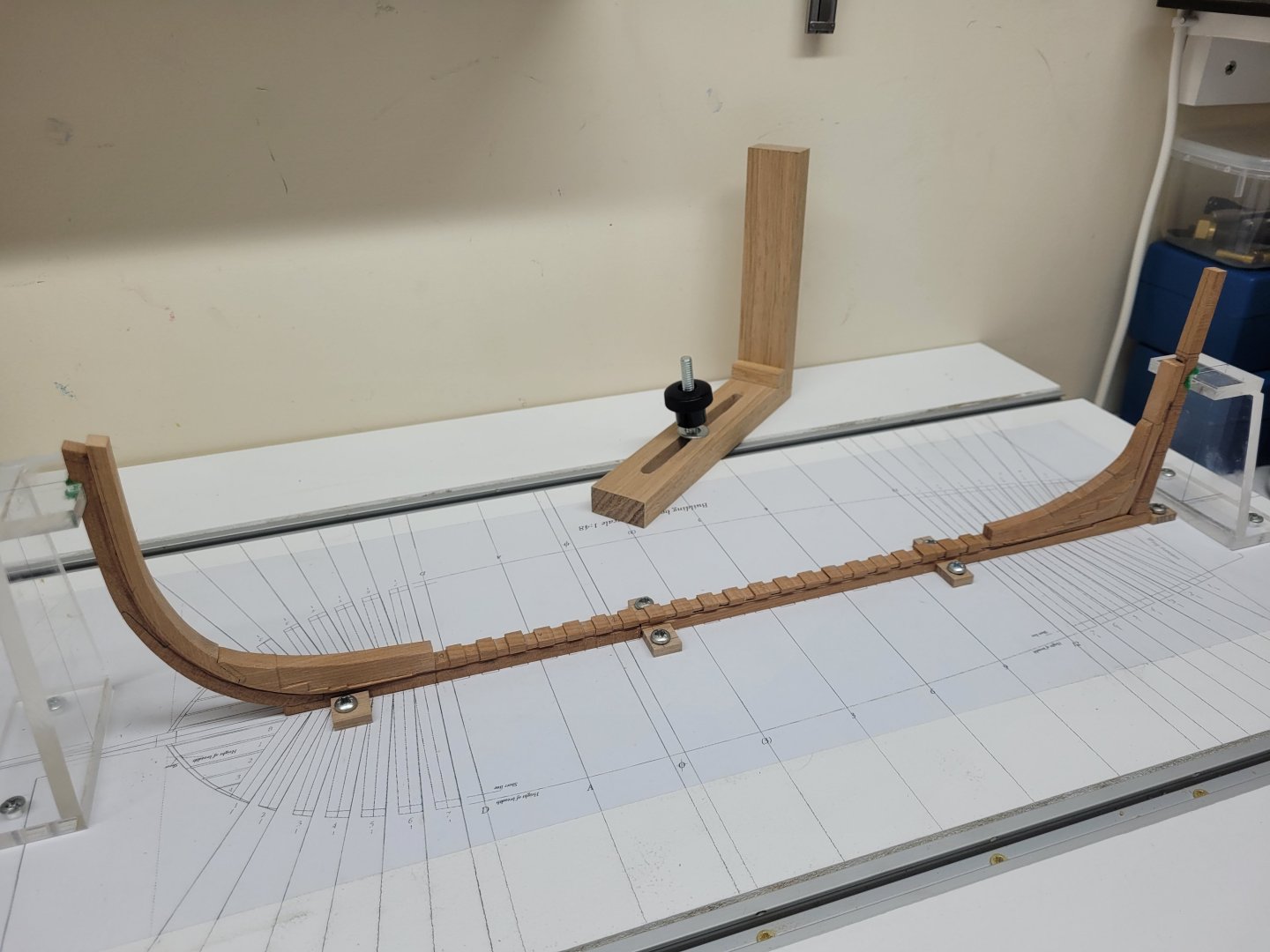
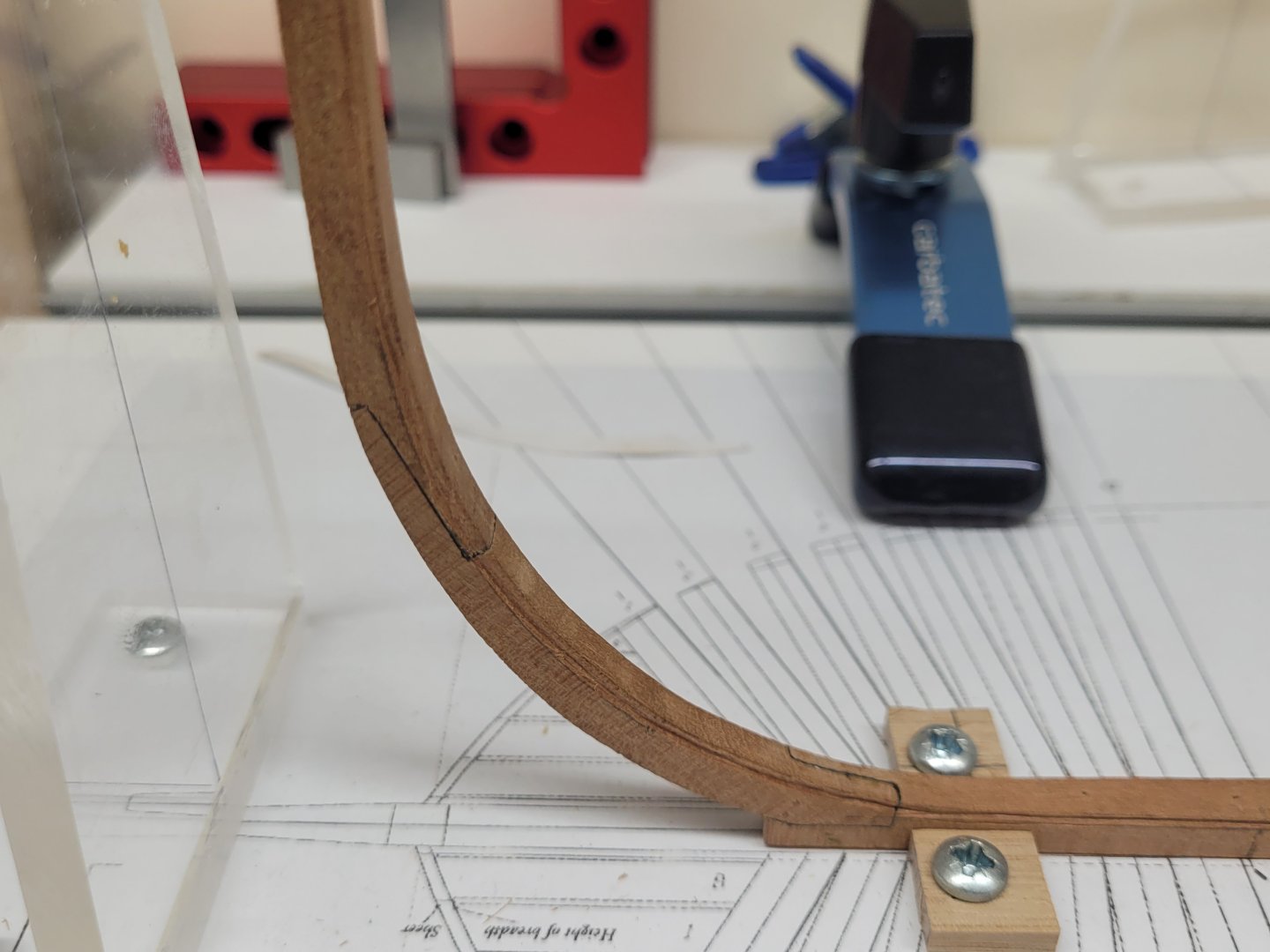
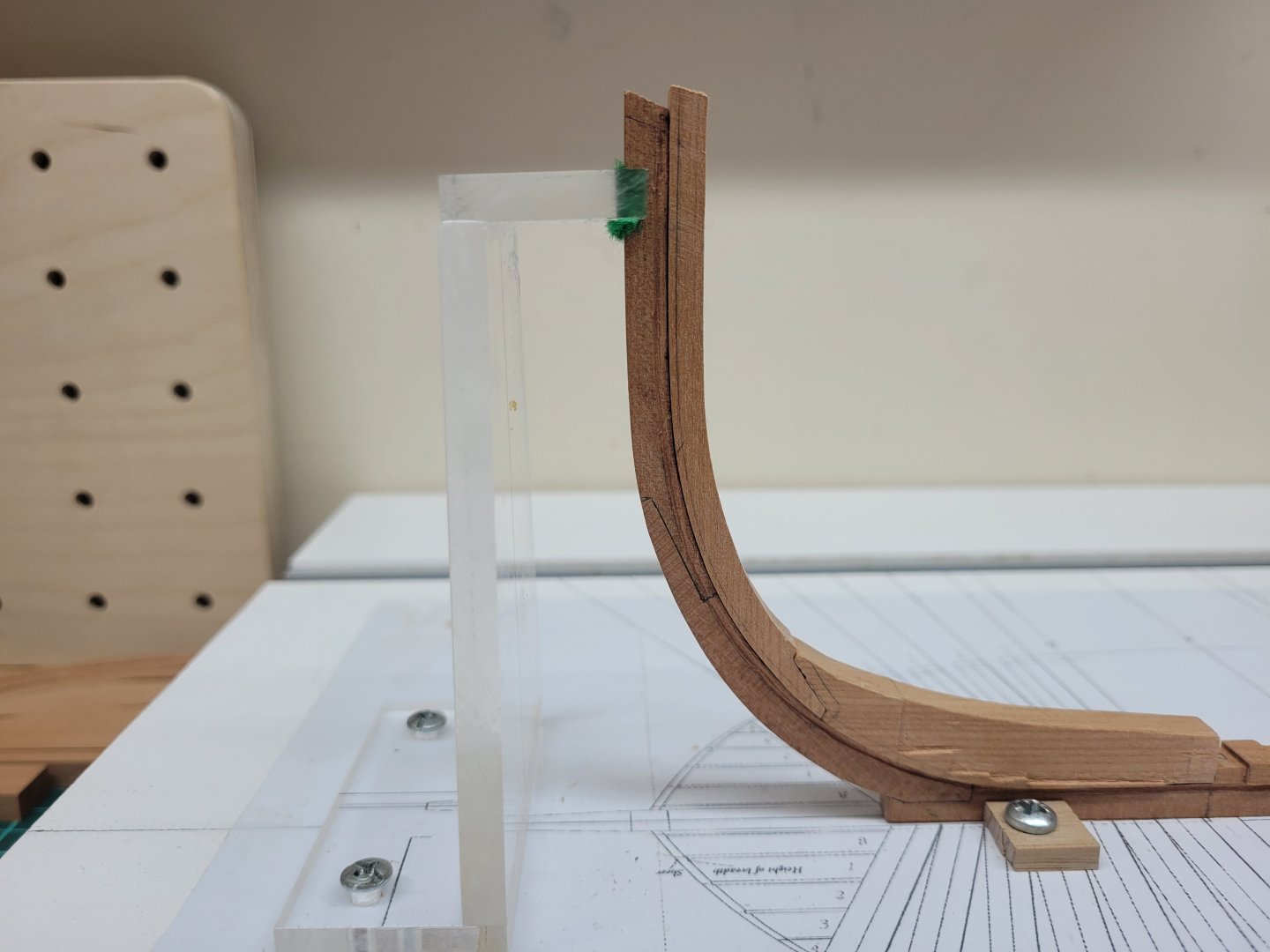
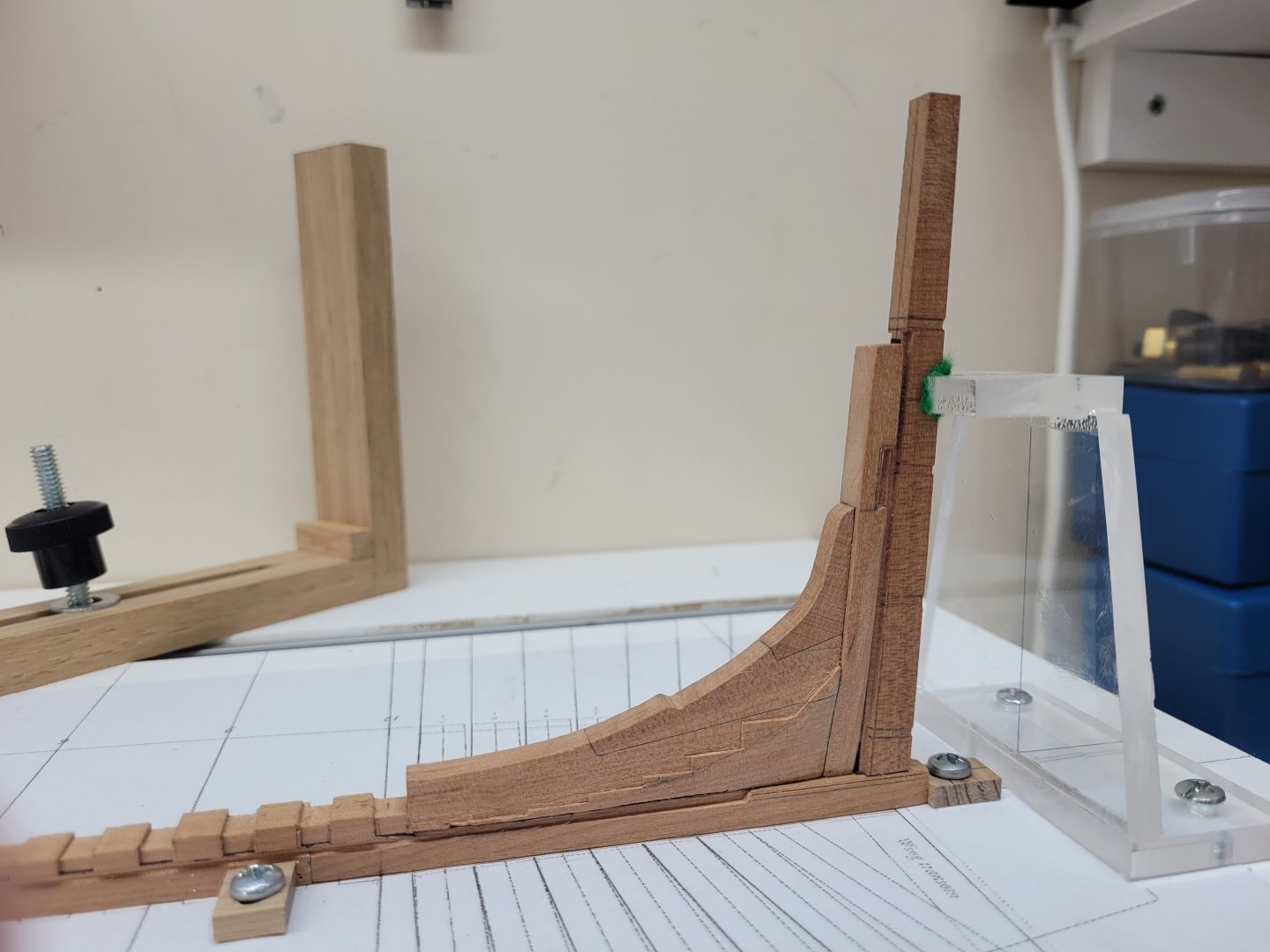
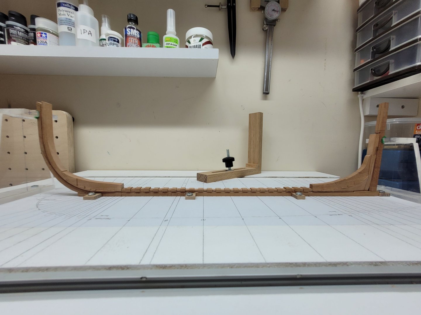
I continued work on the rabbet, focussing now on the area at the fore end of the keel and up the stem. It was easy enough to continue the line of the rabbet along the straight part of the fore keel and when I reached the curve of the stem I proceeded very slowly as this area basically had to be done freehand. I was able to find a flexible piece of wood slightly taller than the thickness of the stem that I was able to lay on the inside of the curve to use as a guide to stop me wavering too close to the inner edge of the stem. Even so it required light and repeated passes with the gouge and plenty of pauses for resharpening to get the line of the rabbet established on each side of the keel. Again, I probably haven't cut the rabbet quite as deep as is required yet but I can go over that again at a later stage when the bollard timbers are in place and can act as a guide. With the rabbet out of the way for the time being I returned to the fore deadwood and finished cutting the rest of the steps towards the rear of the piece. The are six steps in all on each side and the difference in height between the last three is very very small. I did the best I could to make sure they were even and matched each side but I found it very difficult to get them exactly the right height without risking the very aft one breaking off. This may be something I also need to revisit later in the build before adding the relevant frames. I also removed the rest of the excess width at the rear of the fore deadwood which had been left in place to keep the piece square and level whilst the steps were cut. This brought me to the stage of being able to to assemble all of the various pieces on which I have been working for the last few months. Firstly, I glued the rear half of the keel to the front section and then drilled and inserted copper wire for the bolts in the scarph joint. I then installed the fore and aft deadwood and the rising wood on the keel. The stemson was then glued in place and finally the sternpost was added. With the sternpost in place I was then able to install the stern support on the baseboard. It was exciting to finally see all of these pieces come together after working on them individually for so long. It felt for quite a while that I wasn't making that much progress but at least now everything is there to be seen together.
- 92 replies
-
- 15
-
-
Work has been a little slow on the Hayling Hoy build of late as I haven't had as much time to devote to it as I would have liked. Most of the time I have been able to find was concerned with trying to make a scraper with which to cut the rabbet. I used some single sided razor blades and attempted to cut out the required shape using the dremel and some cut off wheels and small files etc. However I didn't have a great deal of success with that - I'm not sure whether the cut off wheels etc were not thin enough or whether the blades were not really that suitable but I struggled to make anything suitable. I decided to return to the v gouges to see if I could improve my skills with them. After a lot of practice I found that securing the keel on my workbench against a slightly taller block of wood allowed me to make some long straight passes with the gouge and achieve a passable rabbet. I worked very slowly taking off the tiniest fraction of wood at a time and resharpened the gouges frequently. I haven't gone as deep with the rabbet as is required I think but I feel that it might be wise to stop at this point and then have another go at deepening the rabbet later on in the build when the keel is all in one piece. For the rear of the rabbet where it presents a different profile in the keel I mostly used some small chisels to make out the area that needed to be removed. The transition between the rear section of the rabbet and the section cut with the gouge is a little shaky at the moment but I will attempt to neaten that up in due course. The rabbet has now been cut in both sides of the rear two sections of the key and the next stage of work will concentrate on the slightly trickier prospect of cutting the rabbet on the curve of the stem.

- 92 replies
-
- 14
-
-
Hello and welcome!
-
Hello and welcome !!
-
Halò from the Highlands of Scotland.
jpalmer1970 replied to Highlander's topic in New member Introductions
Welcome to MSW! -
Looking very good!
-
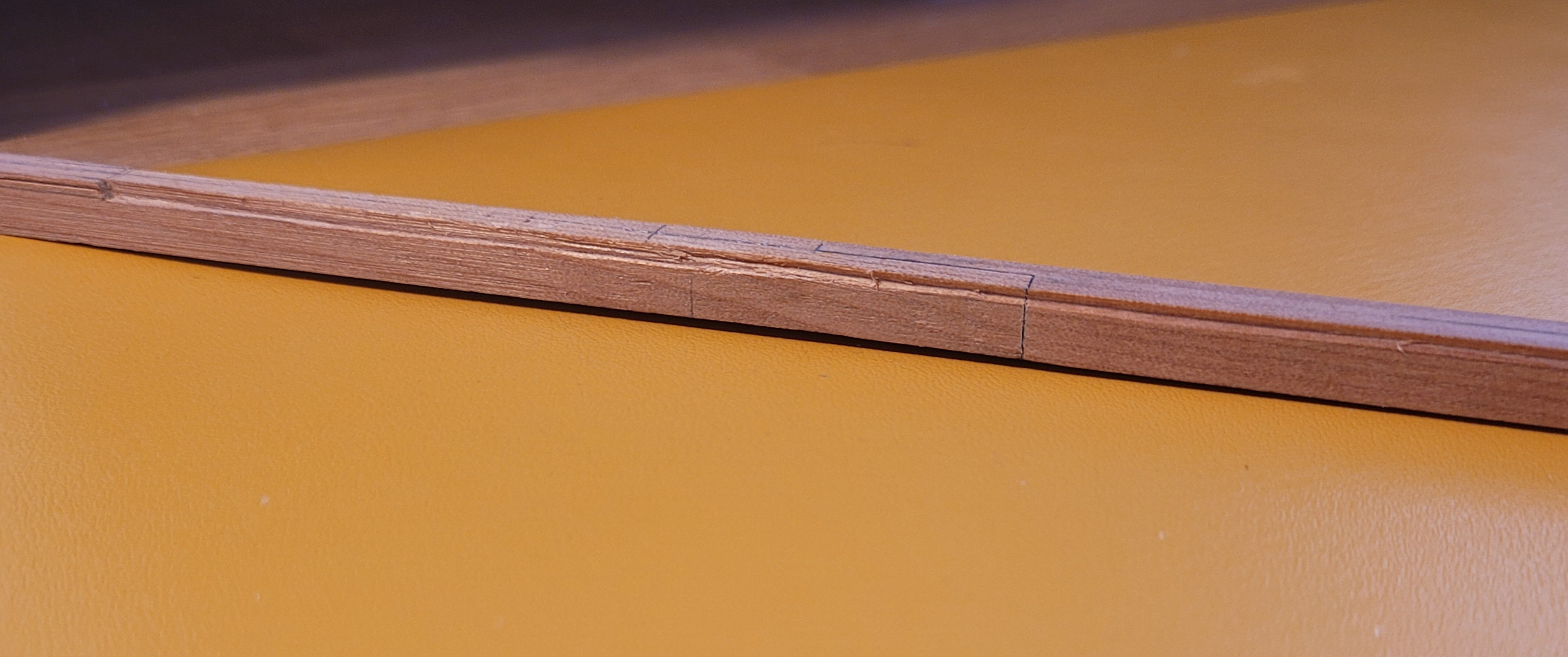
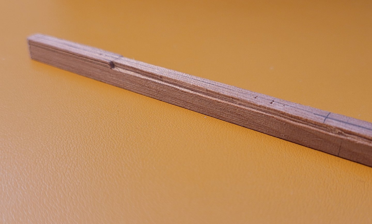
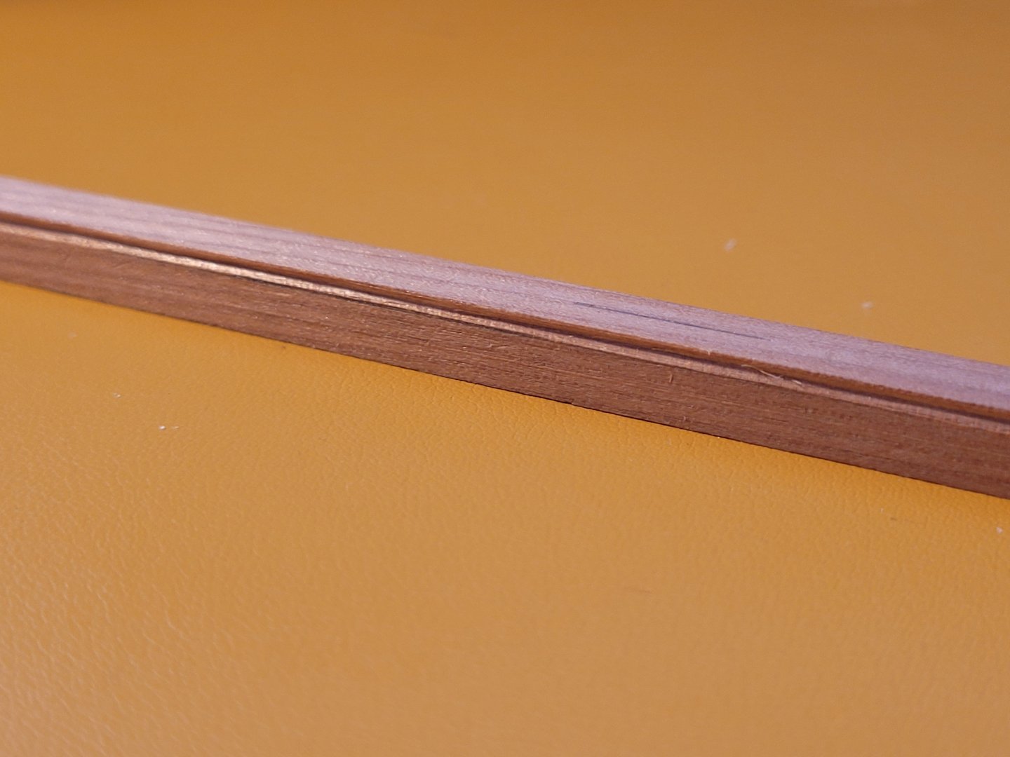
I spent a while practising with the v gouges on some scraps of wood seeing if I could make an acceptable rabbet. Obviously one of the key points is making sure the gouges are super sharp and whilst I had bought the sharpening block with the gouges I don't think I have yet mastered the best way to get them really sharp. I found that if I used the miniature Veritas marking gauge to score the line where I wanted the centre of the rabbet to be it certainly made things easier when using the gouge, as the score line was just significant enough to help stop the gouge from wandering off the straight line. I also spent a while reading volume 1 of TTFM to see how the rabbet was tackled there. David seemed to assemble all of the keel pieces and install the rising wood and deadwood before tackling the cutting of the rabbet with gouges. In contrast Stuntflyer in his excellent build log for the Hayling Hoy cut his rabbet before attaching the rising wood and deadwood and he used a scraper cut to size from a hacksaw blade. Presumably it would be difficult to use a scraper if the rising wood and deadwoods were already fixed in place, hence the difference in approach. As this was my fist time trying to cut the rabbet I wasn't confident that everything would go well enough for me to risk fixing the rising wood and deadwoods to the keel first as that might require a lot so re-dos if things went very wrong with the rabbet. I did want to use the gouges though so I decided to not fix the rising wood and deadwoods in place and attempt to cut a small rabbet on the rear two keel pieces - the idea being that if it went well I could then fix everything else in place and then finish cutting the rabbet to the required depth later. As I haven't yet joined the centre keel section to the foremost keel section this meant I could just concentrate on making a nice straight rabbet on these parts, making sure not to take it too far aft and also bearing in mind the changing shape of the rabbet as it approaches aft. I marked out the width of the rabbet on the keel and used the marking gauge to score a centre line of the cut. I worked slowly and carefully and was pretty pleased with how things turned out initially - I got a nice straight cut along the centre portion of the keel on each side. However, things started to go wrong after that point when I started trying a little too hard to make the cut deeper and also trying to navigate the twist in the profile of the cut at the aft end of the rabbet. A combination of a dulled gouge, over confidence and a ham fisted operator resulted is me making a bit of hash of thing and my rabbet line went off track and quite literally gouged into the top portion of the keel leaving it looking rather unsightly. I also found it difficult to make the turn of profile of the rabbet match on each side of the keel - I hadn't really marked those sections out very well and so that was not really unexpected. The result of all of that is that today I cut some new pieces of 12" stock to remake the rear two sections of the keel. The scarph joints have been cut and once the rear of the new keel is tapered in width I can start again on another rabbet and hopefully do better next time. Learning from my mistakes I have also cut another spare two keel sections, just in case another re-do is required, and also some other 12" stock with which I can use to further practise cutting the rabbet. I will also spend some time to see if I can make a scraper as per Stuntflyer's build log to see how that technique compares with using the gouges. I thought I might struggle at this point, so at least I have the satisfaction of knowing I was right about that 😀 At least I only messed up the easily replaceable bits so I am glad I didn't dive in with trying to cut the rabbet on the stem!
-
Hello and welcome!
-
Research in the HMS Ulysses 1797, a Roebuck class ship
jpalmer1970 replied to Kevin Kenny's topic in Nautical/Naval History
ModelShipBuilder seem to be selling Hahn's plans but I not sure if they come with digital copies of the frames etc. https://www.modelshipbuilder.com/hahnplans.html -
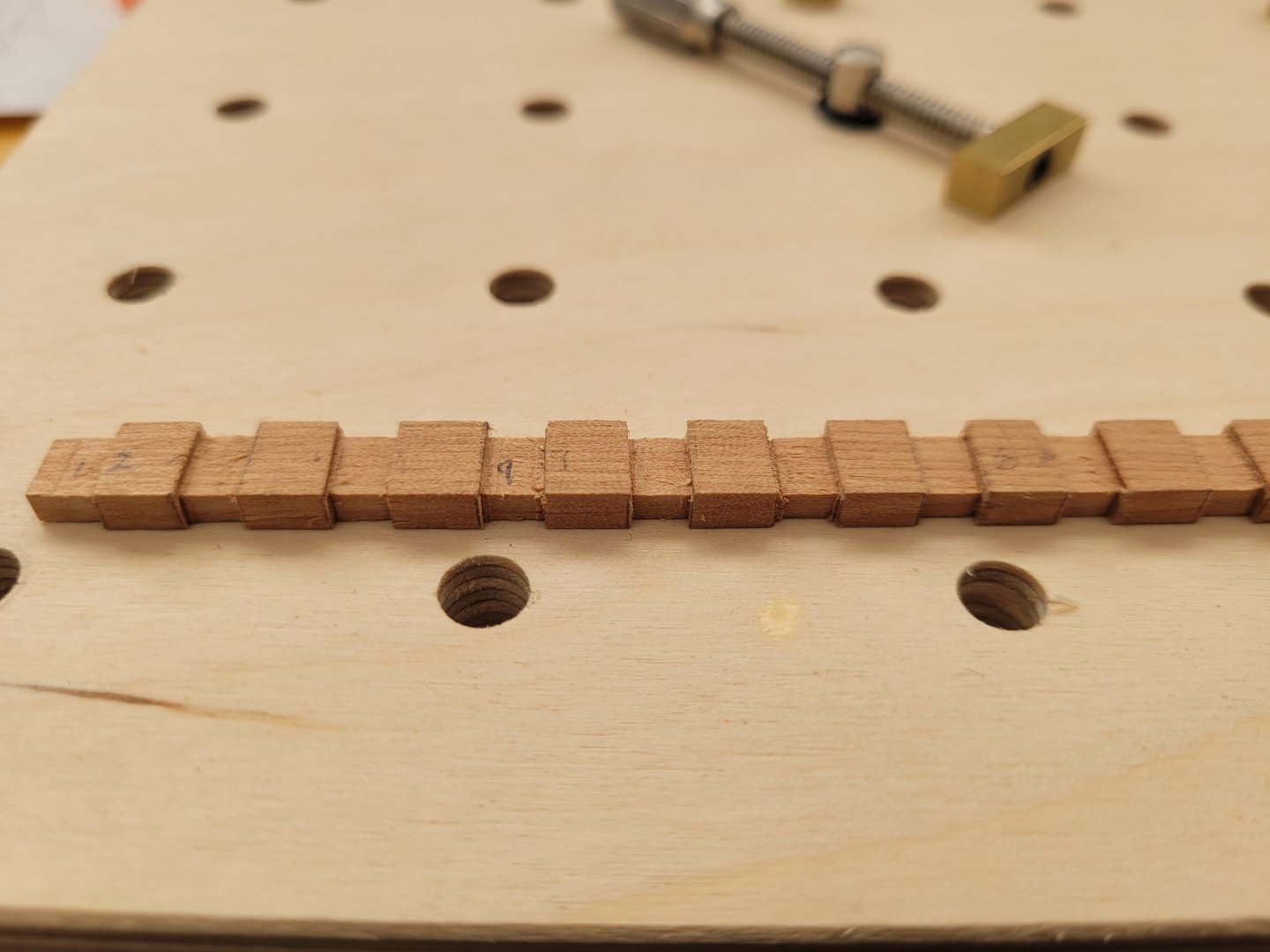
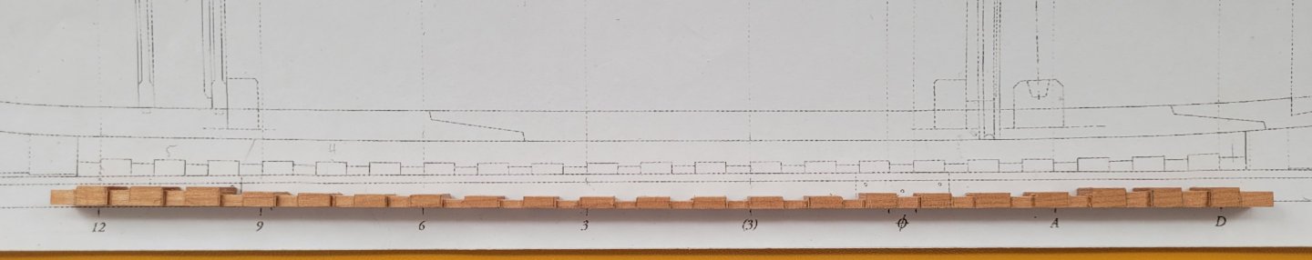
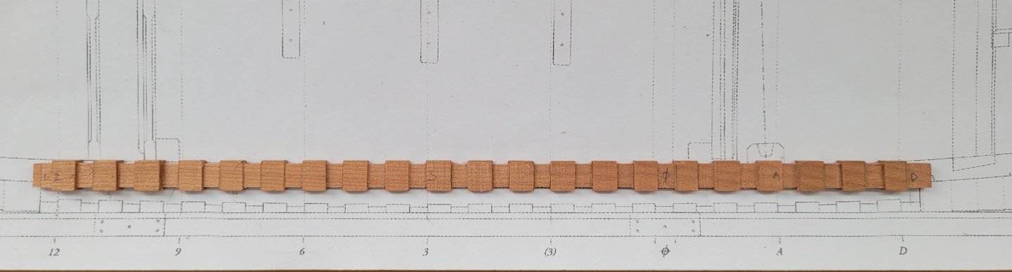
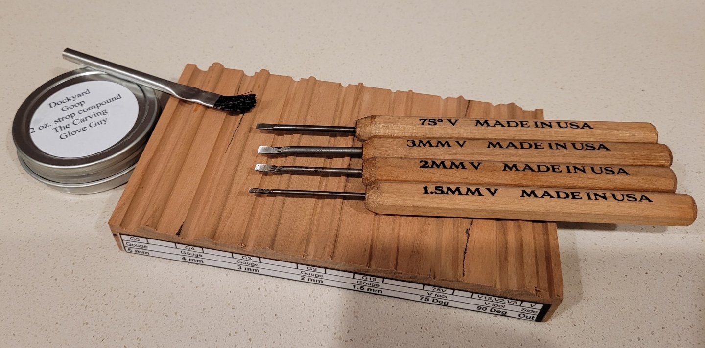
Recent work on the build has focussed on the rising wood. I had previously cut a length of 15" wide stock for this. At its deepest it only needs to be 6" thick but the centre section of the rising wood is considerably thinner than the two ends. I decided it was easiest to cut out the notches for the frames whilst it was one consistent thickness of 6" and then thin down the centre section as required later on. Firstly I marked out the various station lines on the rising wood and then divided these areas into the relevant number of portions for the frames and the separator gaps between them. I'm not sure what the actual terms for these are but that is what i will use! The notches for the frames are 12" wide and the separators between them are 9" wide. A depth of 1.5" needed to be removed where each frame sits. Similarly 1.5" deep sections of wood are also required to be removed from the both sides of the rising wood where the frames sit. I began by cutting the notches for where the frames sit on the top side of the rising wood. I used to mill to do this and then tidied up the edges using the miniature chisels. I was then able to use the edges of the cut lines as a guide to mark out the areas on the sides of the rising wood where the vertical cuts needed to be made. These were then also cut with the mill and tidied up a little with the chisels. I now had the basic shape of the rising wood in place but there was also the question of the taper of the piece from thinner in the middle to deeper at each end. As mentioned previously the rising wood is 6" deep at the first frame separator at each end but at the centre section it is only 4.5" deep. The first three frame separator sections at each end are all the same height and then the next four are 5.25" deep. The next four (which gets us to the middle one) are 4.5" deep. This order is then reversed as you progress toward the aft end of the rising wood. I decided it was easiest to use the mill to gradually shave off the required amount in each area. This of course meant that in the centre when I removed the 1.5" from the frame separator gaps they were in fact sitting flush with the notches for the frames. These notches therefore needed remilling so that they were 1.5" below the tops of the frame separators again. Similarly where I had reduced some of the frame separators to 5.25" deep, the frame notches between them also needed a little remilling so that the notches were again 1.5" below the top of the separator. That all sounds far harder to say and type than it was in actual practice so hopefully the picture explain the process a little more clearly! Here is the rising wood viewed from the side where you can clearly see the difference in thickness between the two ends and the centre portion. And here is the rising wood viewed from above. It does all line up with the plan - I think the position of the lens in the phone camera makes the notches towards the two ends look like they are not in line. The rising wood is a little over length at each end at this stage but will be trimmed to the correct length when I am ready to glue it to the keel. I'l also go over it again with a chisel where required to make sure all the cuts are sharp and square. The next step in the build isn't one that I am particularly looking forward to - cutting the rabbet in the keel and stem. I haven't done this before and so I intend to get a good amount of practise first on some offcuts of wood as I really don't want to mess up the keel and stem pieces! I purchased a v gouge kit to use for this job so hopefully it will work well. Any tips and advice on cutting the rabbet will be very gratefully received!
- 92 replies
-
- 12
-
-
Thank Mike! That would be great.
-
I'd also be keen to purchase Vol II, either as a reprint or a digital copy. If that isn't possible, is there any way of getting the digital files from the CD and plans at least?
-
Good luck with this build. I look forward to following your progress.
-
Congratulations! An excellent model and an excellent build log. You should be very proud of your achievement! 👍👍
- 562 replies
-
- 3
-
-

-
- vanguard models
- alert
- (and 2 more)
-
Intro and interests, from a beginner
jpalmer1970 replied to Desert_Deckhand's topic in New member Introductions
Hello and welcome! -
Hello and welcome!
-
Looks great. The use of the tin foil 'template' is an ingenious way of getting the ensign to the desired shape!
- 562 replies
-
- 4
-
-
-
- vanguard models
- alert
- (and 2 more)
-
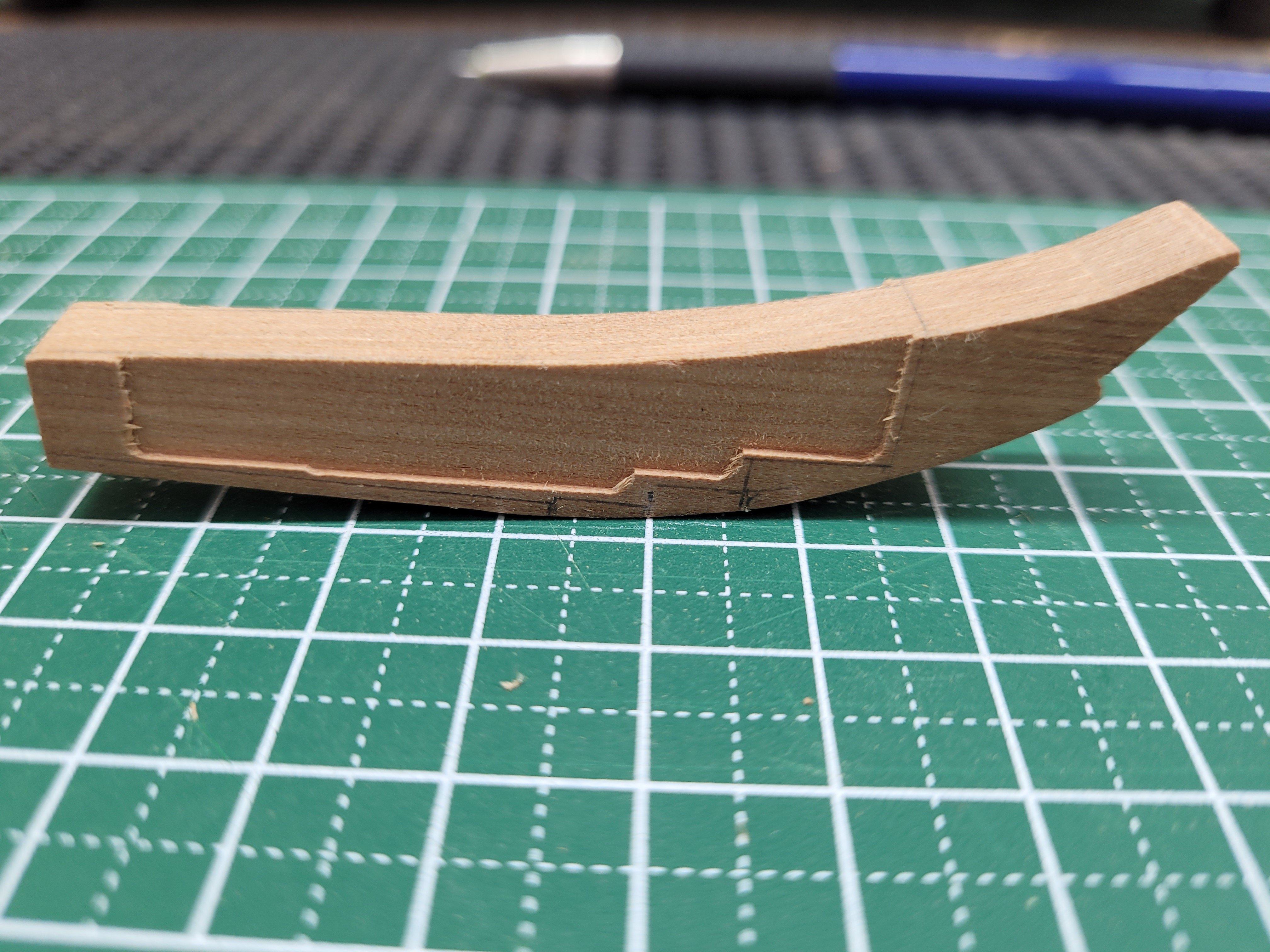
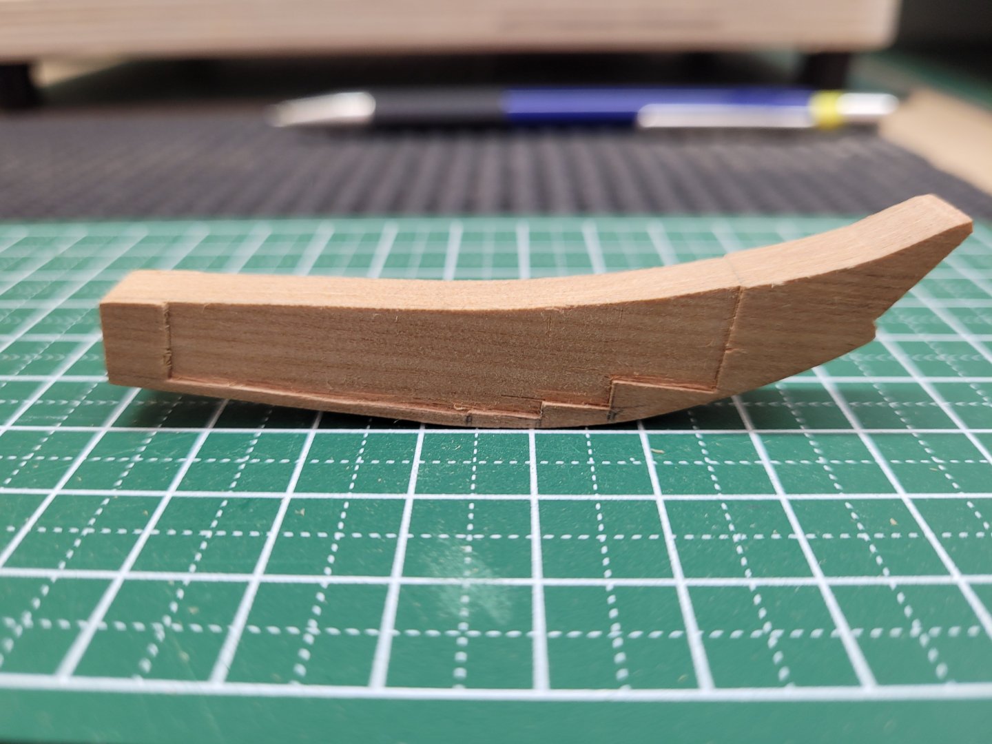
I set about milling the steps in the fore deadwood. A depth of 1.5" needs to be removed from each side of the piece and I removed most of the required area on each side using the mill. I set the depth of the mill bit so that it was flush with the face of the deadwood and then I shimmed the deadwood up by the required amount so that I knew exactly how deep the cut was going to be. I found it was easier to judge the correct depth of cut this way rather than trying to set the mill bit to the correct depth. As you can see I left an area at the rear of the piece simply so that when I turned it over to mill the other side it was able to lay it flat and square on the mill table. These areas will be removed using a chisel when I come to fit the fore deadwood to the keel in due course. After milling out the bulk of the area I then tidied the corners of the steps up using some small chisels. There are in fact 6 steps in all on the fore deadwood and so I still have further steps to cut towards the rear of the piece. However, the steps toward the rear are extremely small and as I mentioned previously I found out that is easy to damage them when trying to fit and refit all the various pieces of the keel etc together. I will therefore wait until the piece is ready to be permanently affixed to the keel before I cut them and finalise that part of the work. At the moment the deadwood is also a little over length and needs trimming to size - this will also be done before the final steps are cut. Here is how the stemson and the fore deadwood fit against the stem at present.


- 92 replies
-
- 12
-
-
No. Seawatch Books sell the plans separately as a supplement to the series - they are available from their website for $45.