


mangulator63
-
Posts
36 -
Joined
-
Last visited
Content Type
Profiles
Forums
Gallery
Events
Posts posted by mangulator63
-
-
On 5/30/2020 at 2:04 PM, KeithAug said:
Thank you Richard.
Unfortunately not a very productive week. Really quite hot and a lot of garden jobs to get on top of.
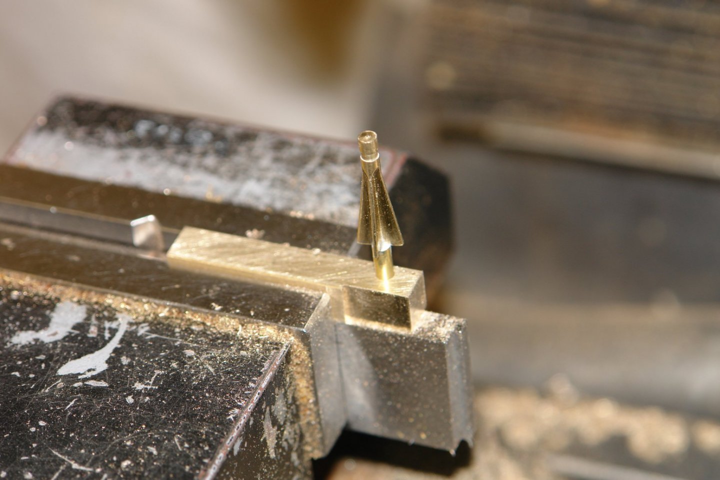
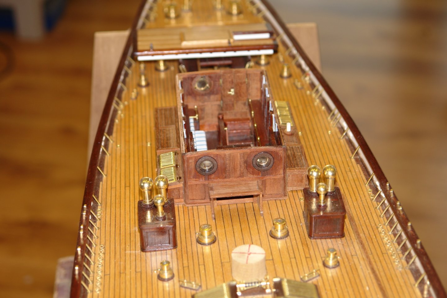
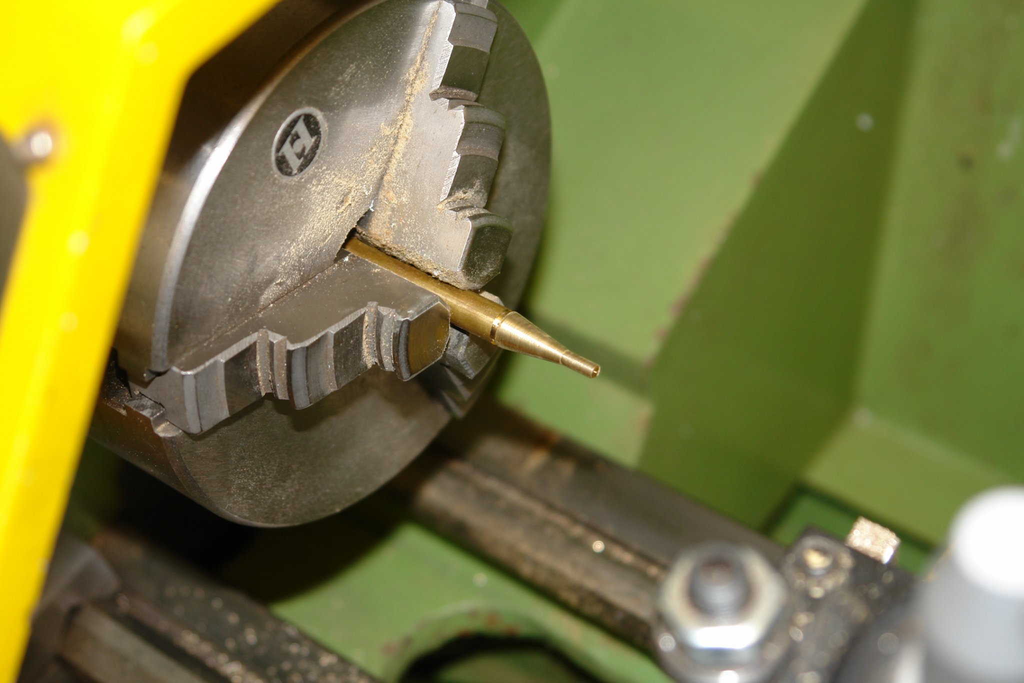
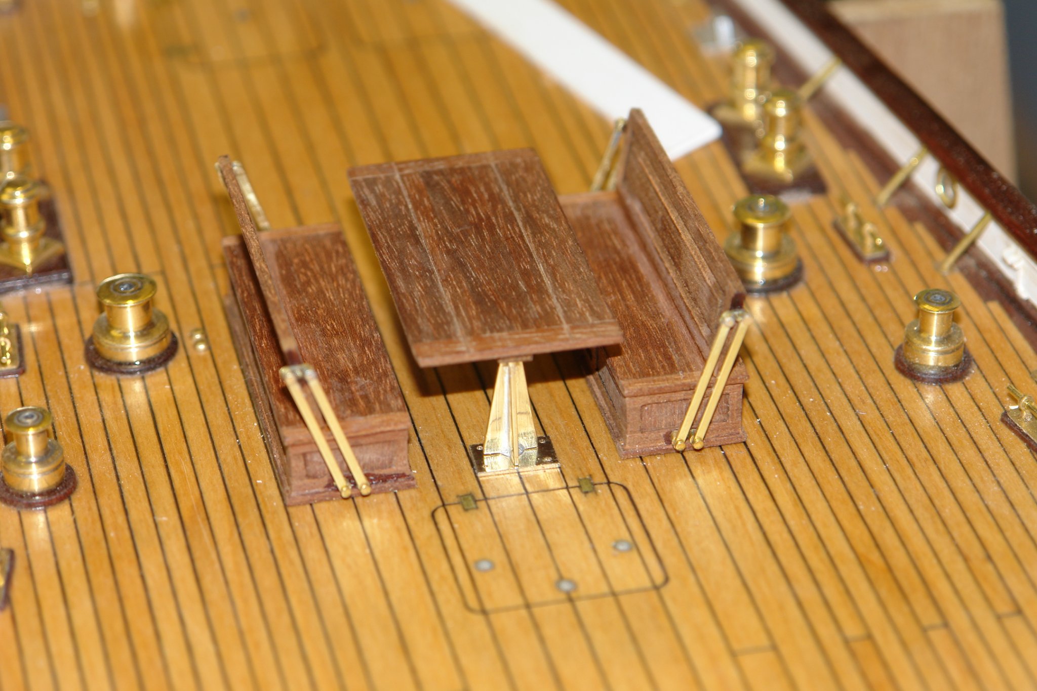
I got on with the deck dining table. This has a flanged support leg - quite unattractive in brown paint but much better in brass. .8 1.1 2.1
I turned the 0.80" long leg as a cone.
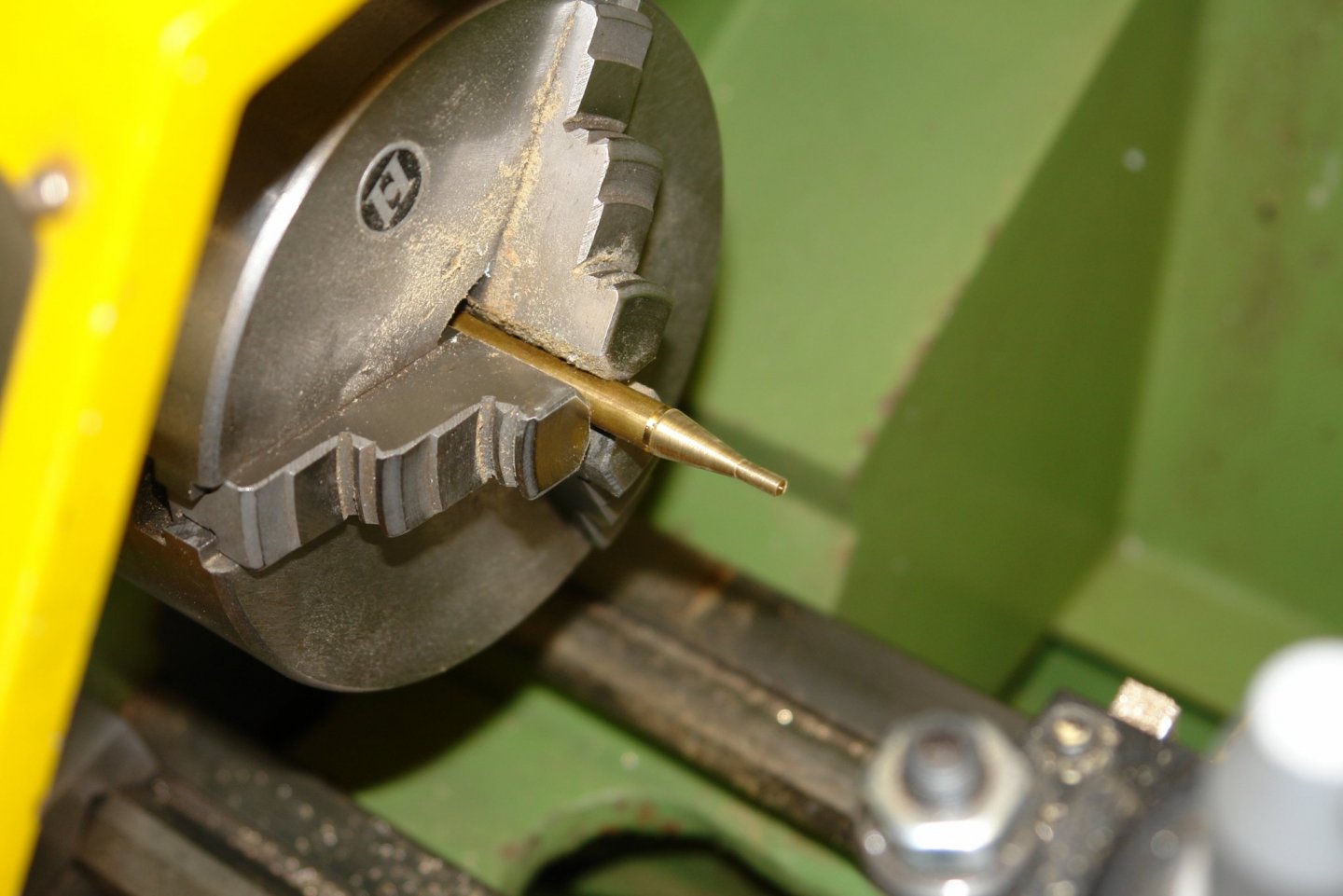
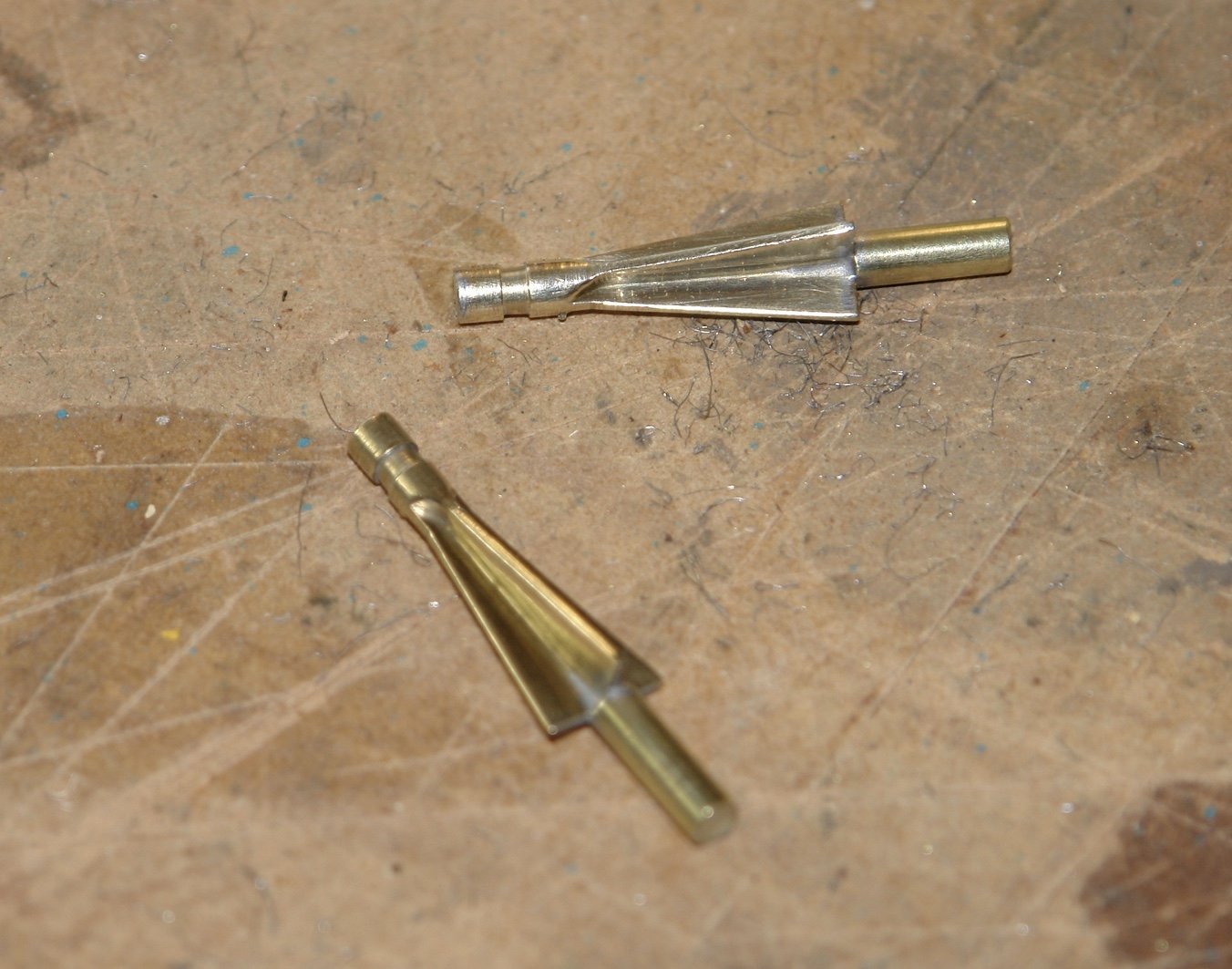
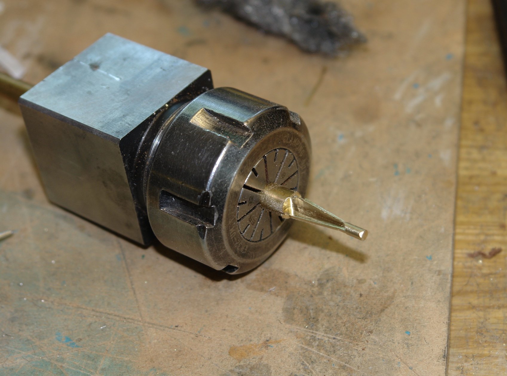
This was then transferred this to the mill to cut away the excess metal to create the triangular flanged leg.

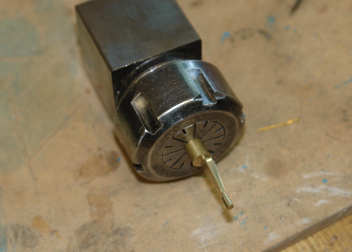
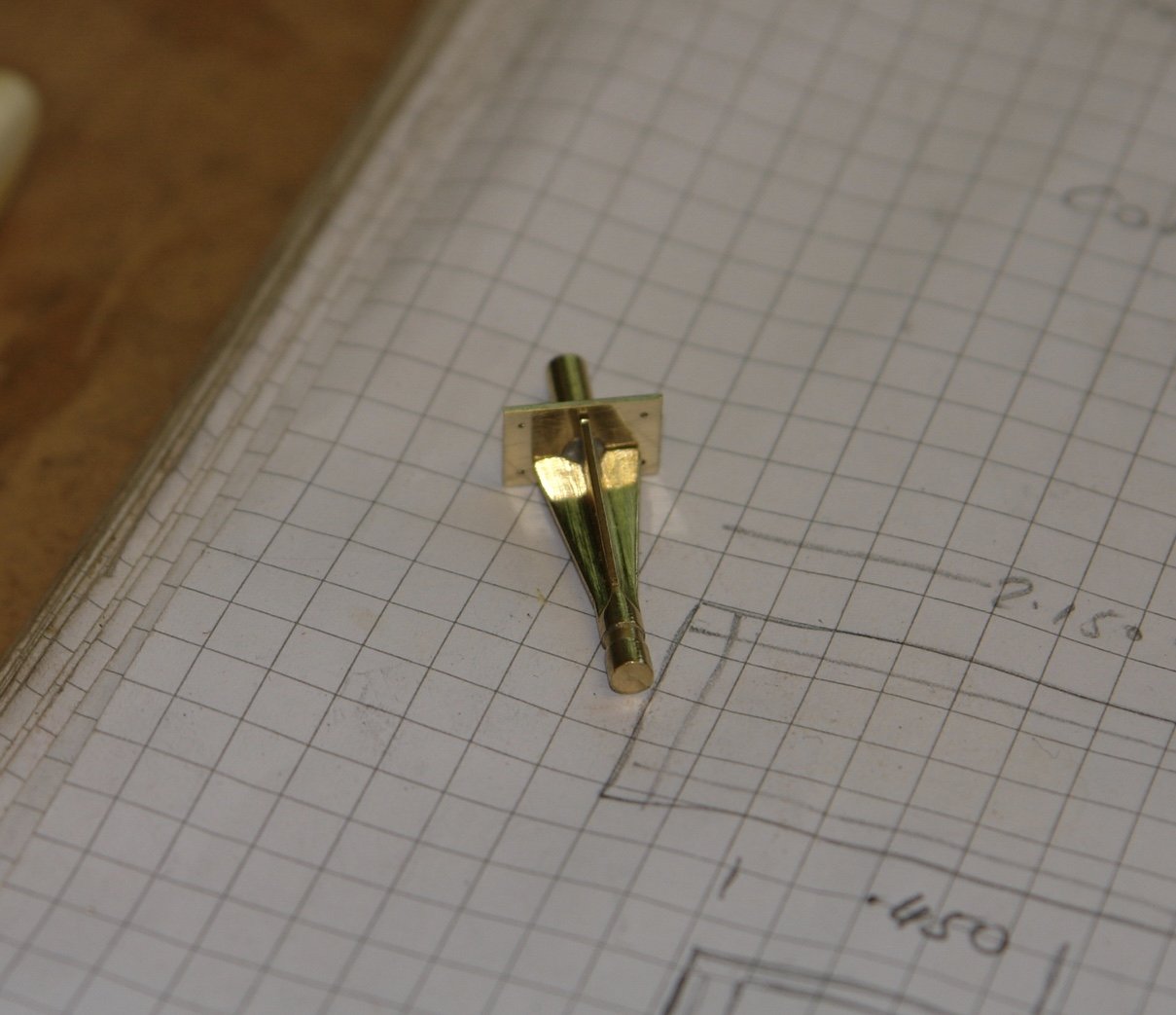
The leg was then parted off to length and a 1/8" diameter spigot was soldered on to the lower end to allow it to be mounted on the deck.
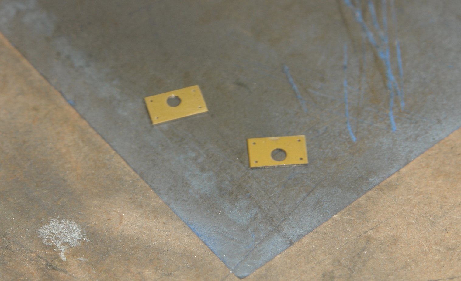
I cut the base bracket from a piece of bar and drilled a 1/8" hole for the spigot and 4off .025" holes for the mounting bolts.
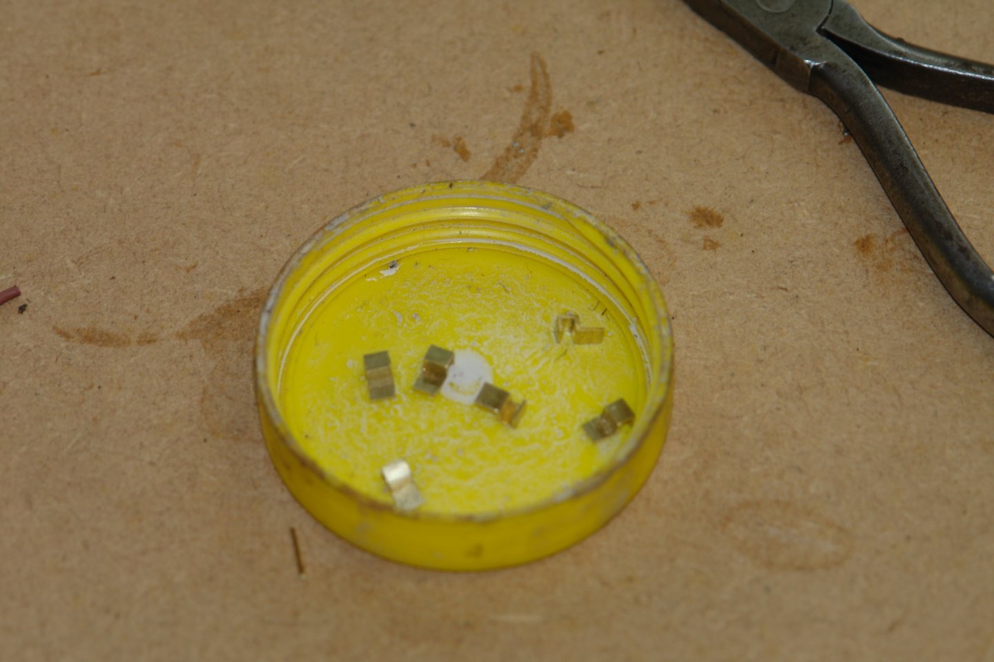
The base plates were then slit to thickness and then cut off and polished.

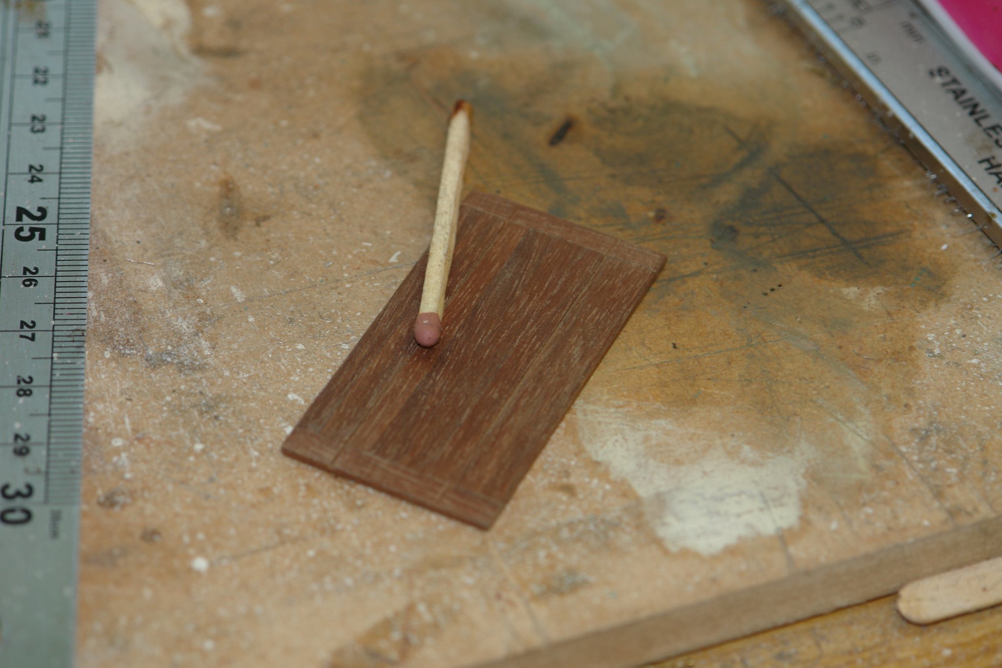
The table top is 1.1' x 2.1' with the two leaves extended. This was made from .060" planks with scribed lines to simulate the leaves.
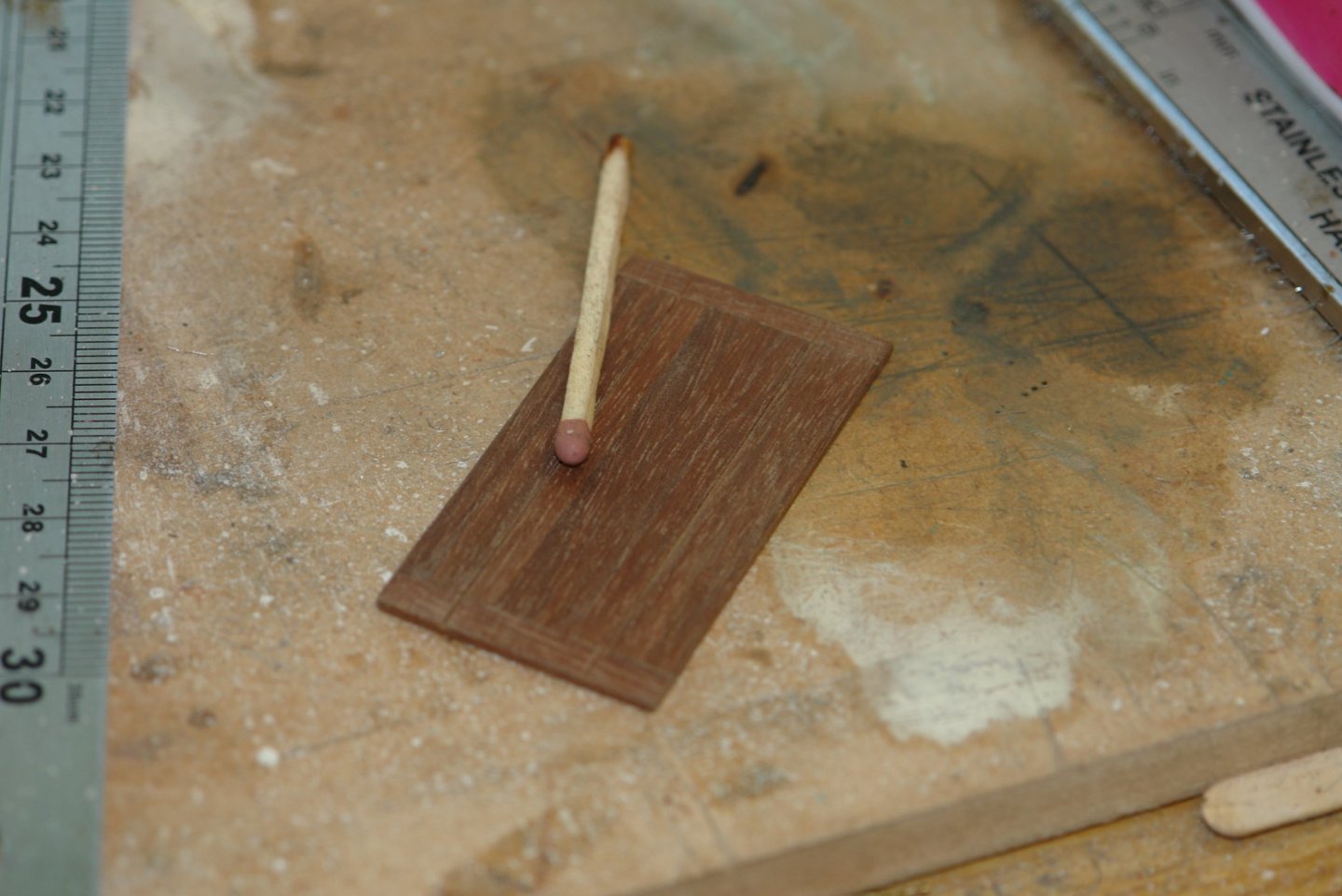
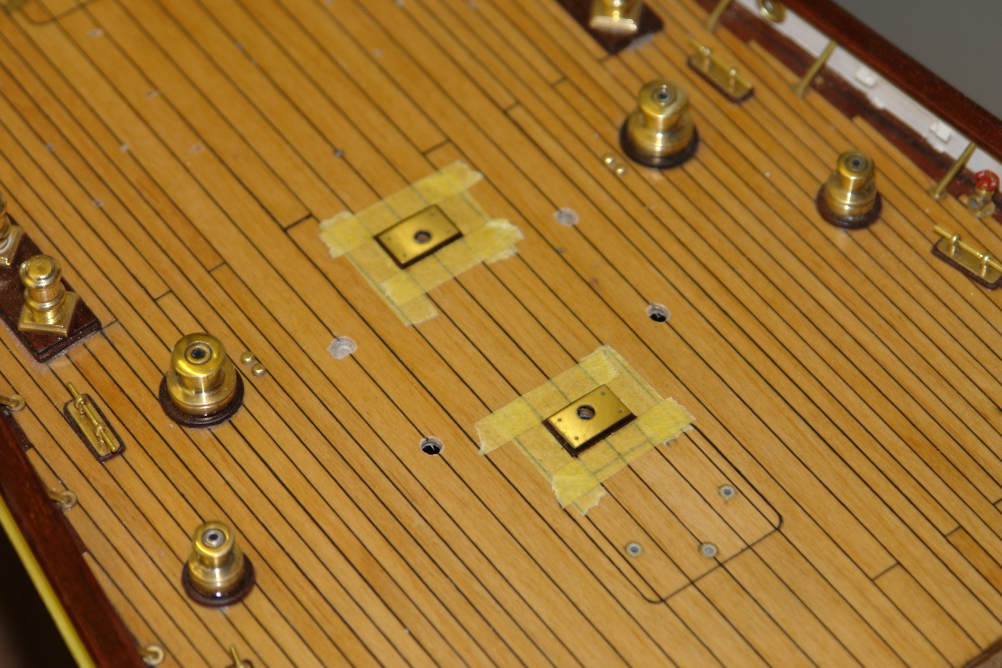
Wooden plinths were mounted on the deck and given a couple of coats of poly before the brass plates were added.

The legs were then added followed by the table top.
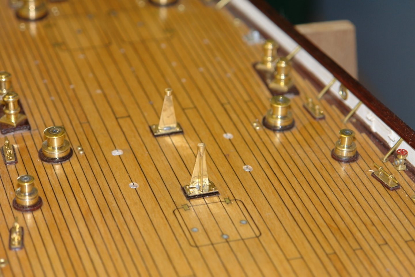

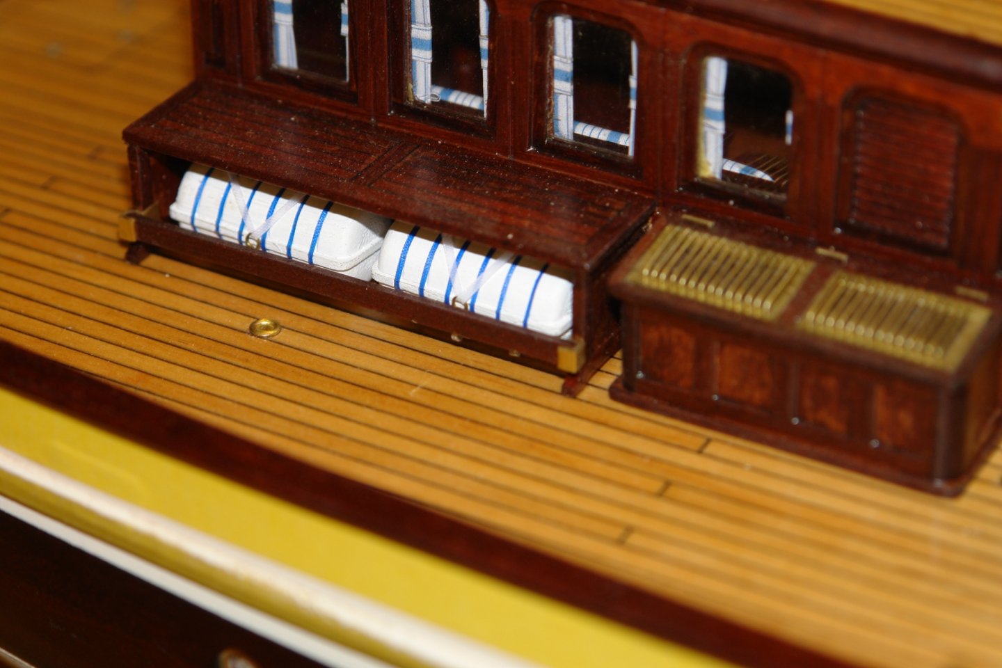
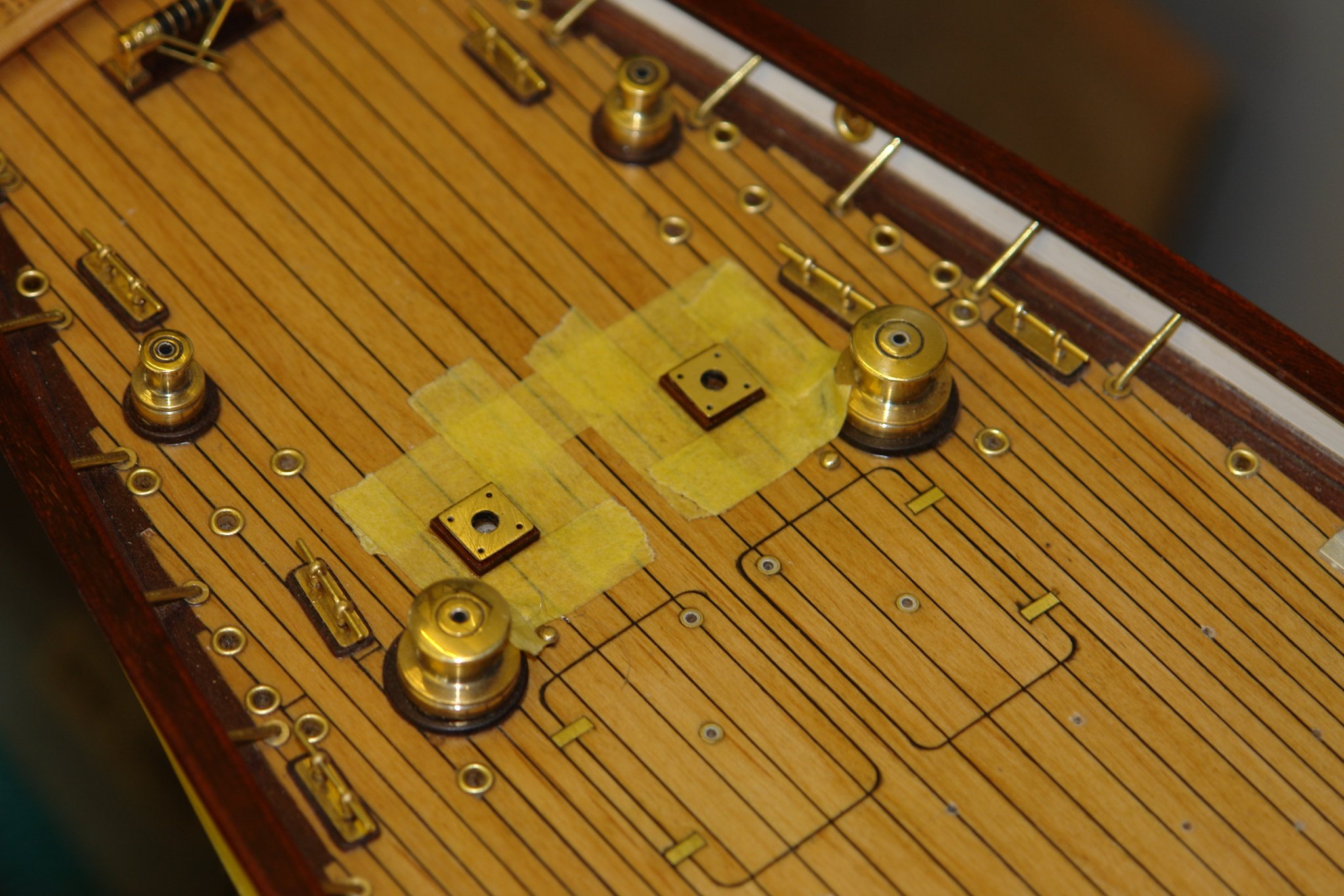
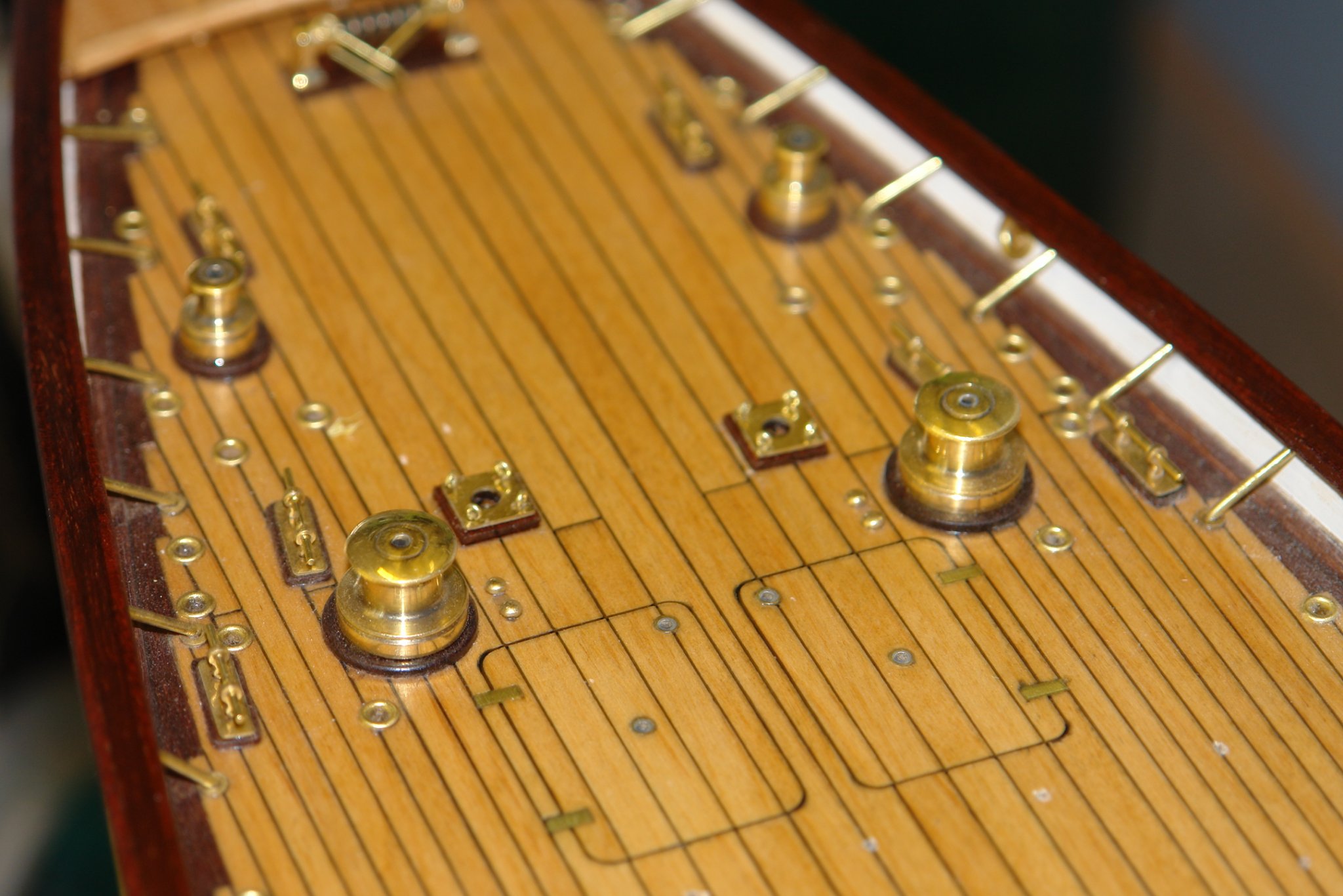
While I was at it I mounted the base plates for the crutch.
4 eyes are located at each corner of the plate - very small and made from .020" diameter brass wire.

I know I said that I was going to get on with the vents - but I got diverted.
Mr. Keith there appears to my old eyes to be a horizontal "U" shaped cross bar located between the base of each table leg. Am I seeing a shadow or did you choose not to add this part because of variations in the design over the years. I haven't read any members responses mentioning that you have not included it, so I'm probably just seeing a shadow on the deck.
Your impeccable adherence to fine details has me rereading each post, looking at images of the real vs. your creation and comparing how you have so meticulously replicated in scale such minute details. BRAVO!
Respectfully, Tim
- KeithAug and Keith Black
-
 2
2
-
16 minutes ago, Roger Pellett said:
Keith,
Having recently published a book, actually two books; my first and my last, it can be a time consuming task. For me, writing it was the easy part. The hard part was done by two talented inviduals employed by a local museum that graciously donated their time.
This included word processing my individual chapters into a cohesive format, tracking down owners of copywrited materials and getting written permission to publish their work, and getting illustrations that I selected into a form that could be published. I was also fortunate that one of these “helpers” was a retired university research librarian who knew what needed to be done. I was also responsible for hiring someone to index the book. The other was a recent University graduate with bulldog determination. She recently independently published an article about Great Lakes shipping and attended the Steam School on board the Liberty Ship in Baltimore Harbor.
My librarian friend also spent considerable time writing and organizing the materials to send to prospective publishers, each of which required a business plan for the book. Once a university press agreed to publish the book they insisted on a single point of contact: me. In the ten years since retirement I had focused on things other than up to date computer technology so communicating with them was a hurdle to overcome.
MSW is blessed with some talented authors who have produced wonderful books of stunning artistic quality published mostly by SeaWatch. The fact that they not only built amazing models but also produced high quality books speaks volumes about their ability. In my case, however, without the help that I received from others my book would still be nothing but a good idea.
I see you were fortunate to have someone donate their time in assisting you with your book publishing. I wonder if another possibility for assistance might come from a local college. I was wondering if college students taking classes on writing or publishing look for ways to earn experience by assisting others put their book together. I feel that amount of information, idea's, images and witnessed skill in this thread alone are well worth publishing.
In my opinion Keith's work should be published in a larger size format with full page color images and possibly a "CD" for the scalable .pdf files.
Again just my opinion.
- KeithAug, druxey, Roger Pellett and 2 others
-
5
-
On 3/22/2020 at 3:07 PM, KeithAug said:
Thank you for your comments Eberhard. I agree small bits do take a disproportionate amount of time and eyestrain is a limiting factor. I must get more practiced in wearing a magnifying visor, to date i have always failed to master the technique.
Yes Richard modelling can become a bit obsessive.
Pat - actually no filing involved - the following should explain:-
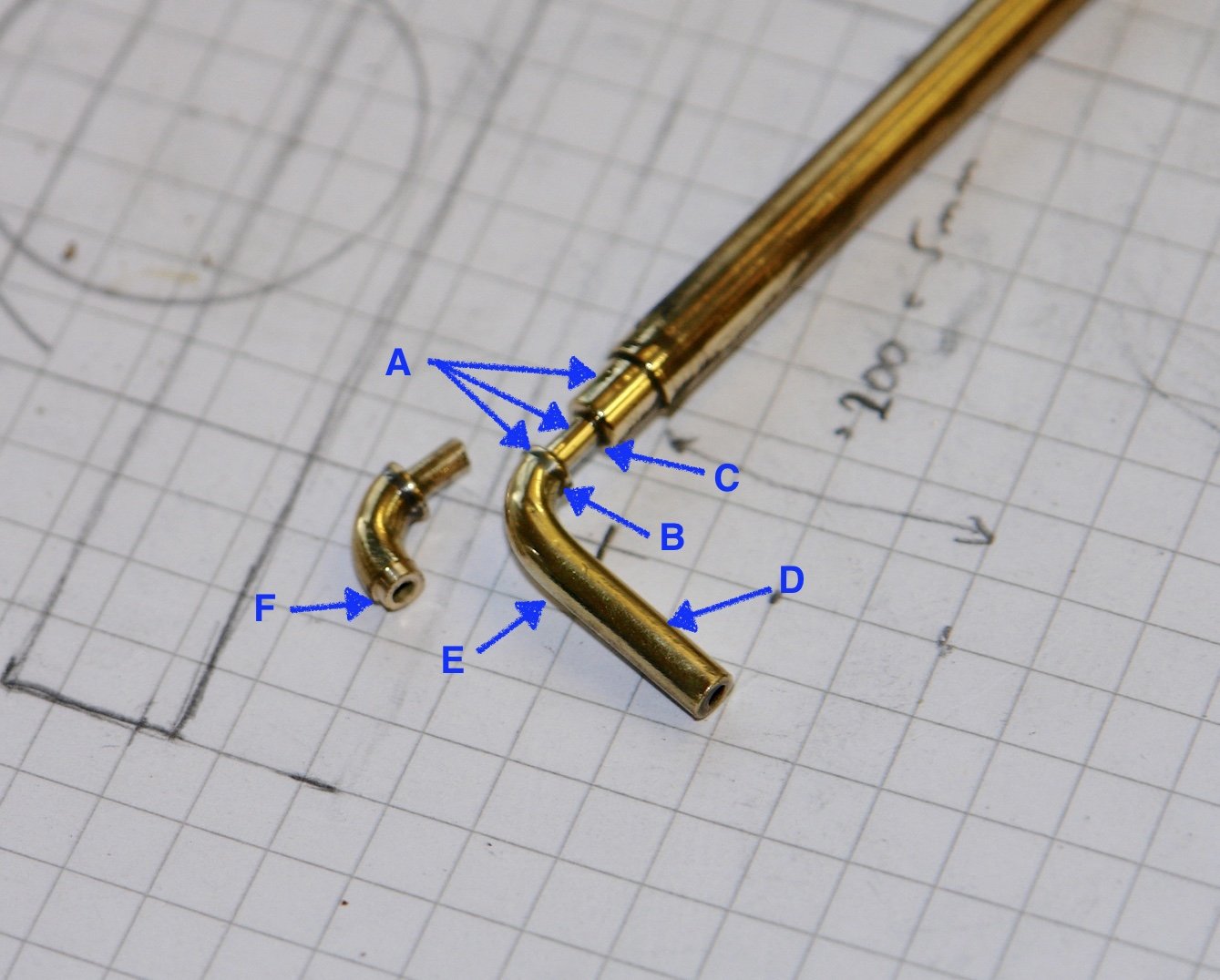
I first turned the diameters "A" on the rod to the upper right.
I then soldered on the elbow at point "B".
I then cut off the the upper right rod at point "C".
I then held the elbow in the lathe chuck using the shaft at "D".
Then I turned a diameter at "E" using a parting tool. This formed the spigot diameter "F".
I then parted off the elbow from the shaft.
The flange was then turned and fitted on the spigot.
I found a set of Dental/Medical Loupe's with an attached LED Light work great.
-
I made several jigs for gluing parts together out of a cheap teflon cutting boards I purchased from a dollar store.
You can cut blocks or long panels that allow for clamping parts to and CA will not stick to it.
I purchased a few, one for a base and then the others to cut out the blocks or shapes needed. You can even thread holes in it for using threaded fasteners to make jigs that need to be set to the base.
- mtaylor, Bob Cleek, Estoy_Listo and 1 other
-
4
-
On 2/21/2020 at 5:03 PM, KeithAug said:
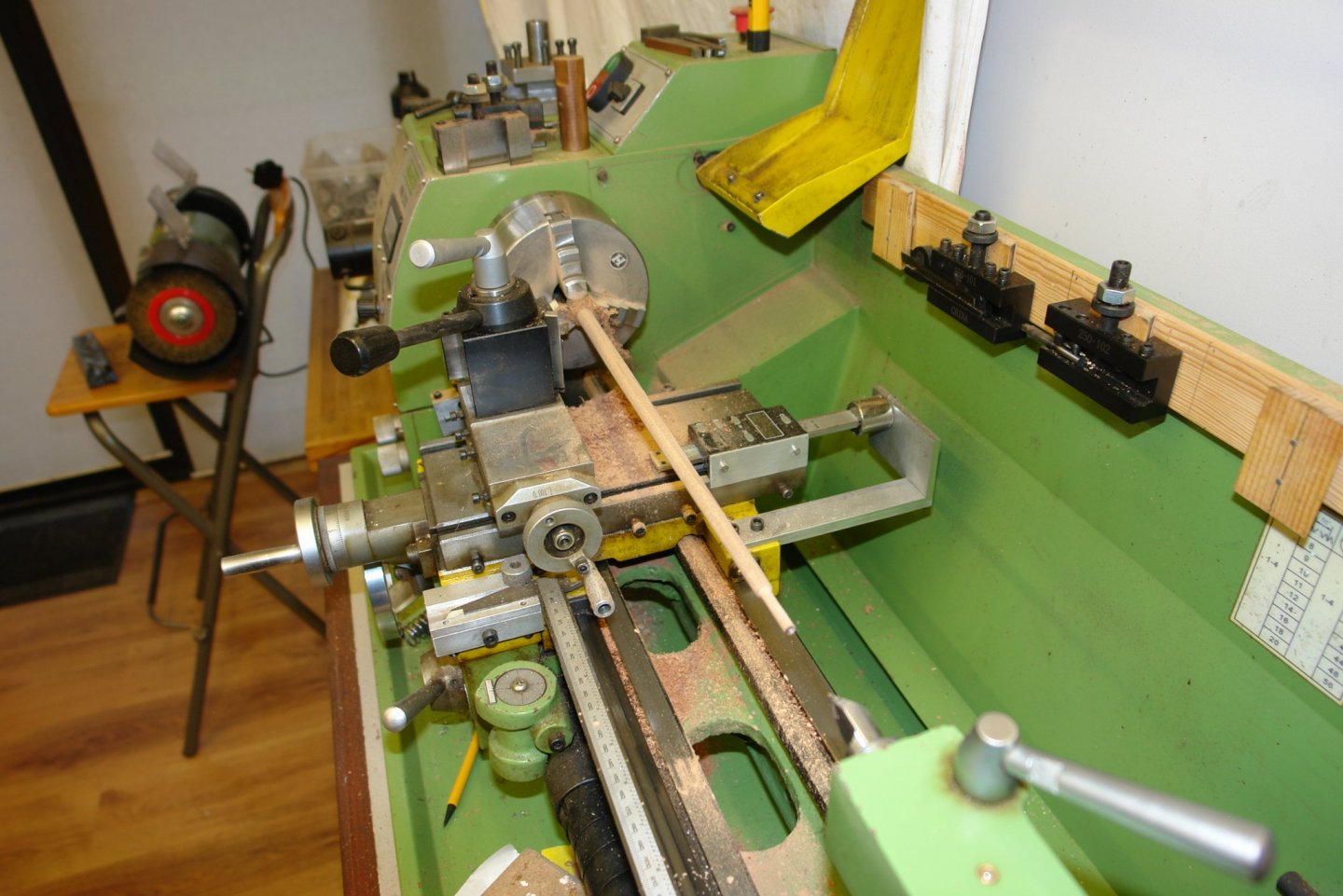
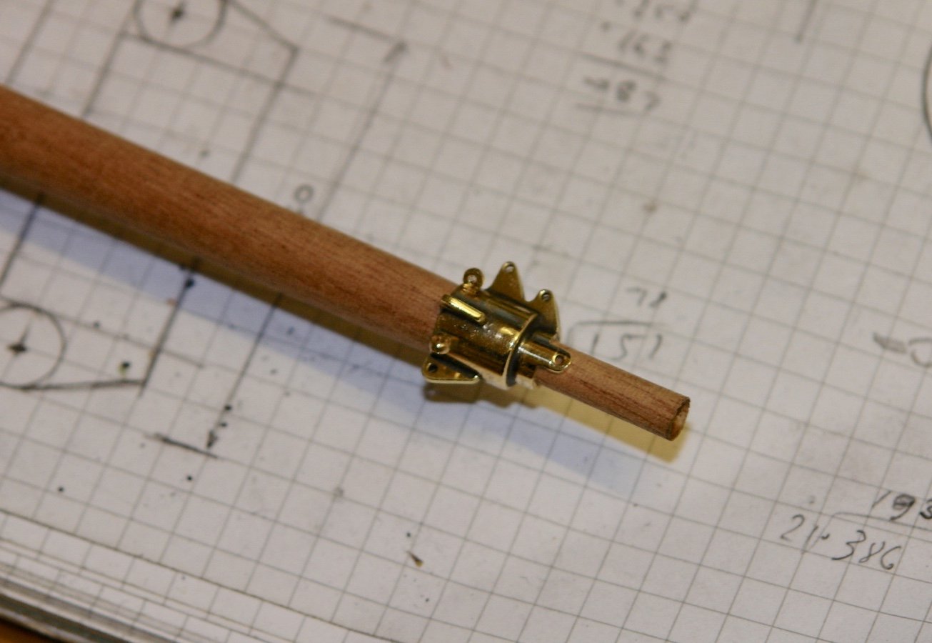
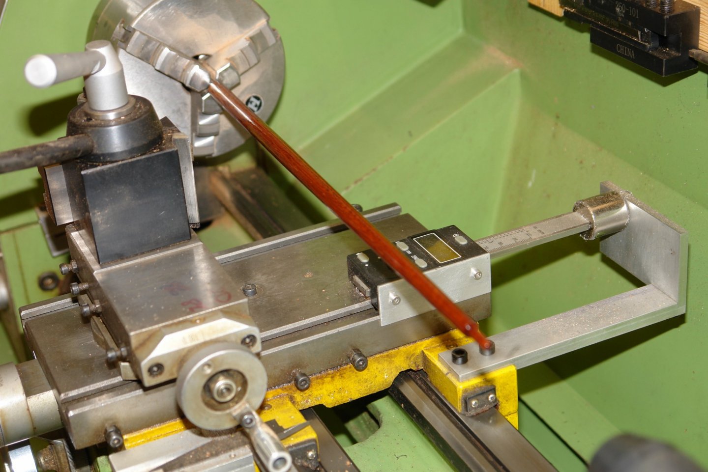
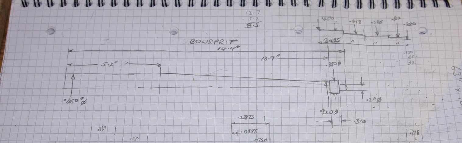
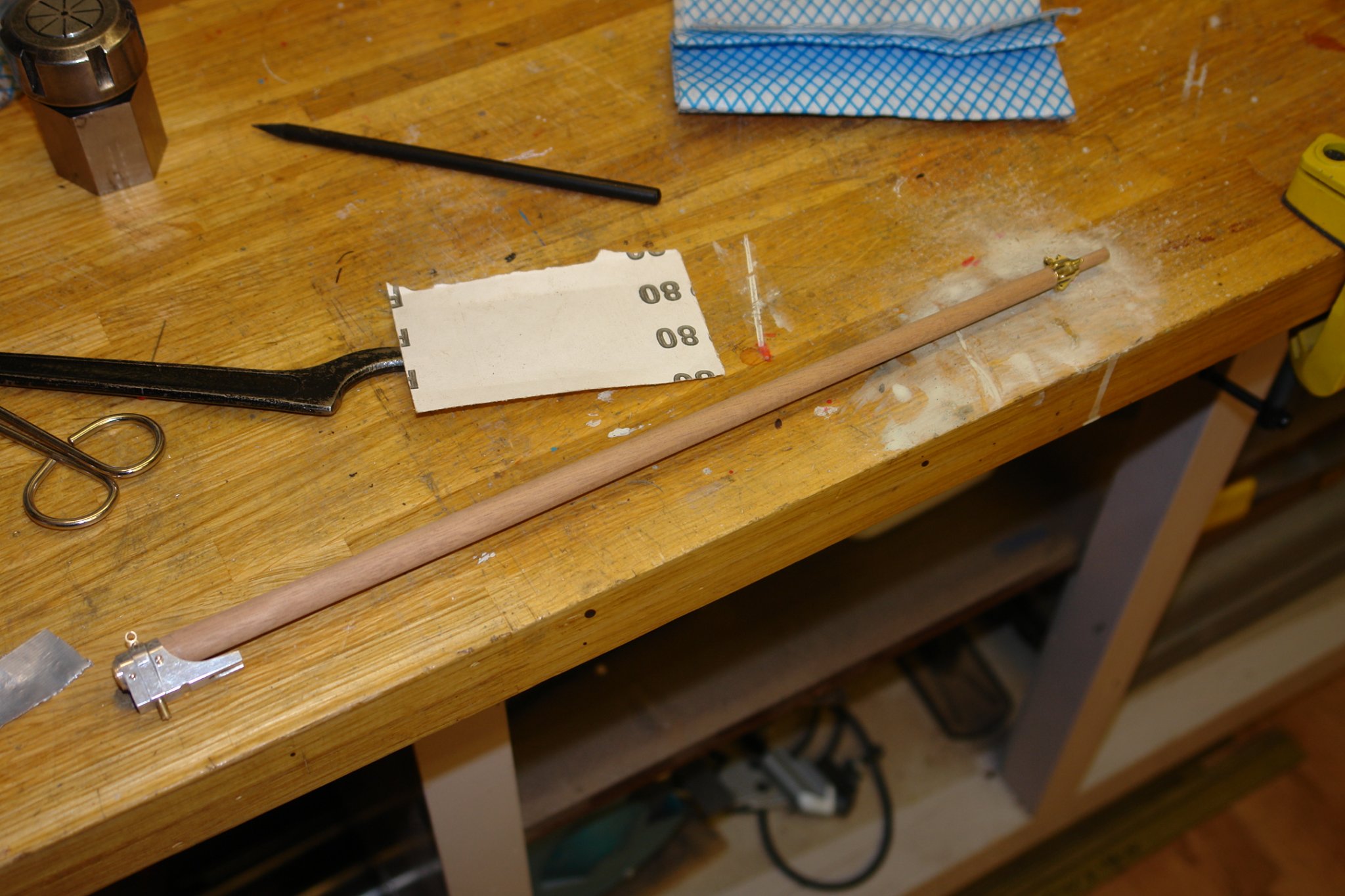
Having made the cranse iron the next logical step was to make the bowsprit. The bowsprit is some 14 inches long with the first third parallel at .450" diameter. The second 2/3 tapers gradually down to a diameter of .320". I had a piece of .5" diameter sapele left over from my previous build and I turned this on the lathe as a series of cylinders of reducing diameters (see top right hand corner of sketch below).

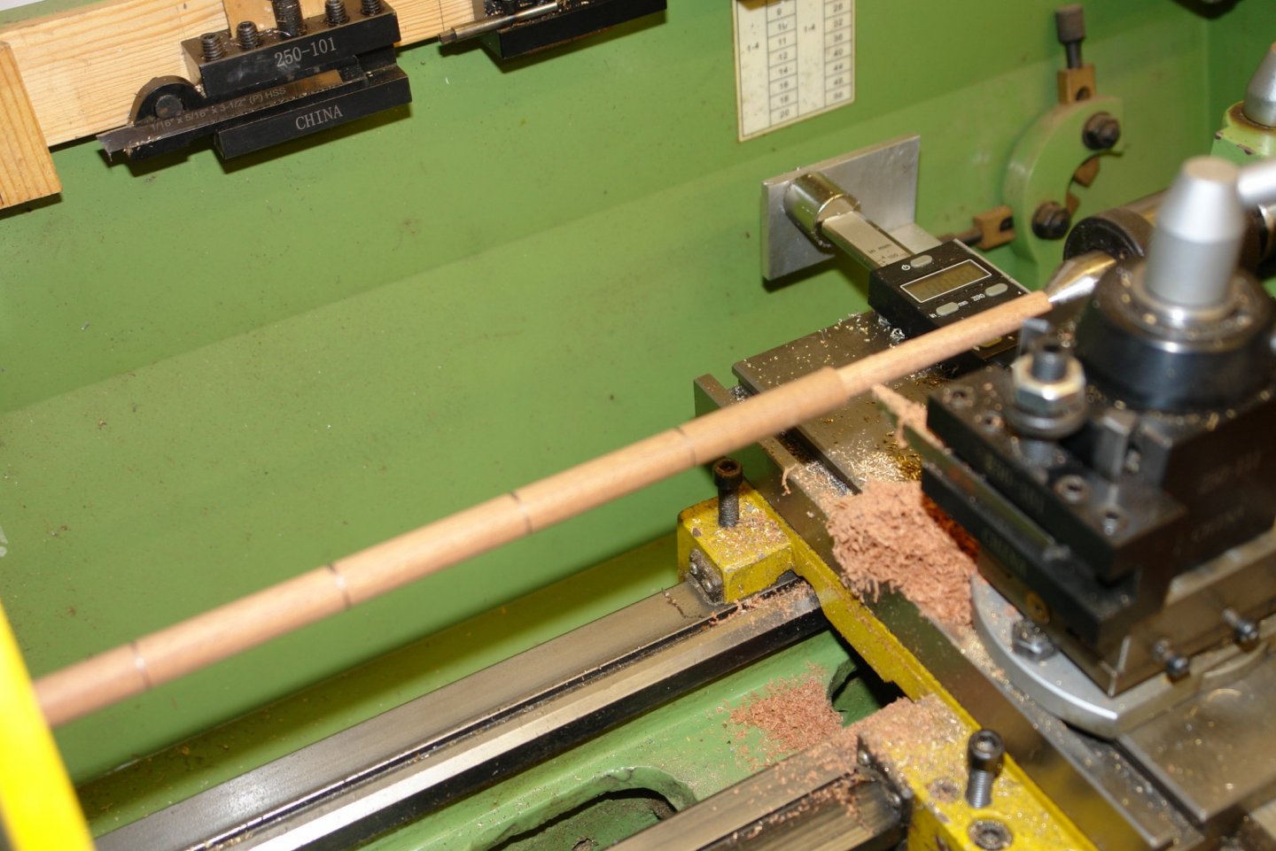
With a slender turning of this type it is often necessary to use a fixed steady (a moving steady can't be used when taper turning). Anyway I decided to improvise by using my cupped hand as a steady and this worked remarkably well but but the friction made my hand quite hot - in reality too hot.
Having turned the series of parallel diameters I smoothes out the steps with sandpaper to get a smooth taper.
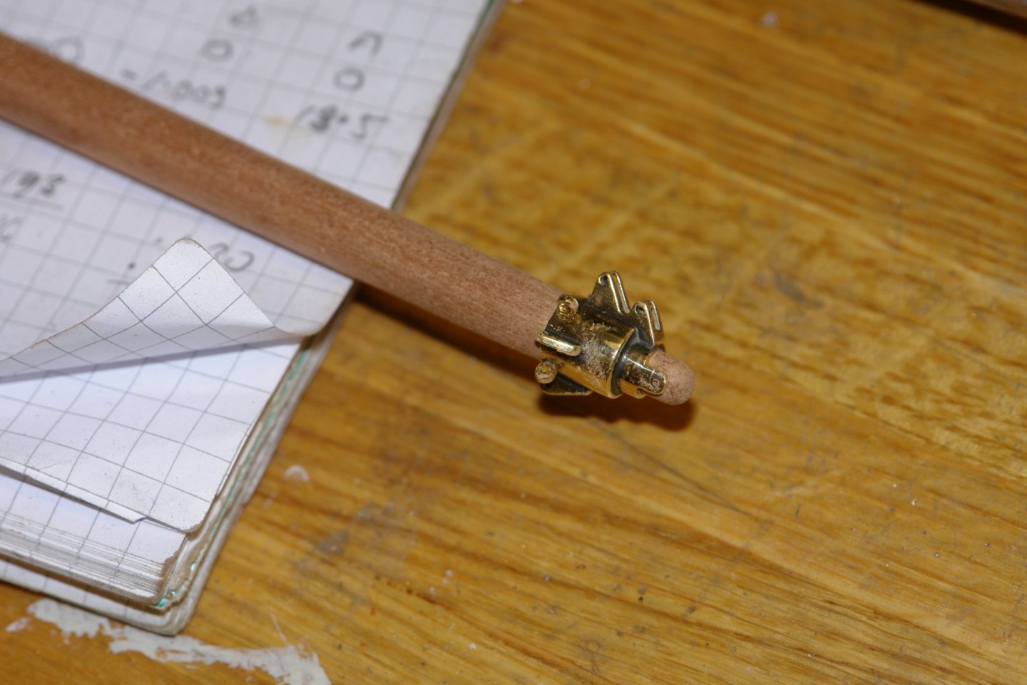
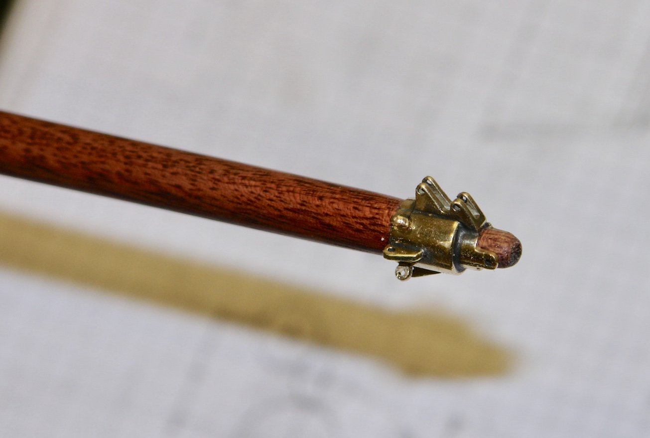
The large end was then bored to take the shaft on the foot and the narrow end was turned to match the bore of the cranse.


I painted the bowsprit with poly while rotating it at low speed on the lathe.
 On 2/22/2020 at 3:37 AM, noel_colledge said:
Druxey, if you put the finish on a lint free cloth first and then apply this to the work, you get no splash regardless of the speed.
While the piece is still mounted to the lathe I have used a method of first saturating the whole piece with thin CA to strengthen it overall. ( I have found saturating a wood part in thin CA after finishing the part to the desired demensions allows for easier and cleaner machining of the wood parts and doing so will not effect the color of the wood if your desire is to keep it natural ) I then sand with progressively finer grit sandpaper until I achieve a fine luster. I have found using a sanding product by the name of Micro Mesh in both pad form and sheet form to be the best to achieve a semi to high gloss finish.
Before removal from the lathe I fold a piece of blue disposable paper towel (The shop kind ) making it 5 or 7 layers in thickness and about an inch wide. I put a "Pea Size" drop of thick CA and equal amount of linseed oil on the towel and with the lathe spinning at a high speed I wipe back and forth quickly pinching the piece between my thumb and finger. I repeat this a few times until I achieve the sheen I desire.
Of course I always cover the machine with disposable towels to keep any drips away from the beds and always I mean always wear safety glasses.
I find this type of finish for masts and spar's that you already have mounted in the lathe faster ( the part is dry in seconds and has a finish ) but also very durable, as I said I believe it strengthens the wood part overall but also the machining of flats or holes drilled afterwards seem to come out cleaner. Any machining marks made after dismounting from the lathe can be sanded and sealed with CA or your preferred finish.
I have also used the " Soaking in Thin CA Method " on smaller wood parts that require shaping to strengthen and preserve shape.
I learned about this method years ago while making Wood Pens on my lathe. A friend had told me about how well a finish it produced along with how much less time was involved in the finishing process. I never went back to using brush or sprayed on finish that added hours to the completion time. There are many websites on this method for those interested.
- KeithAug, bruce d, Keith Black and 1 other
-
4
-
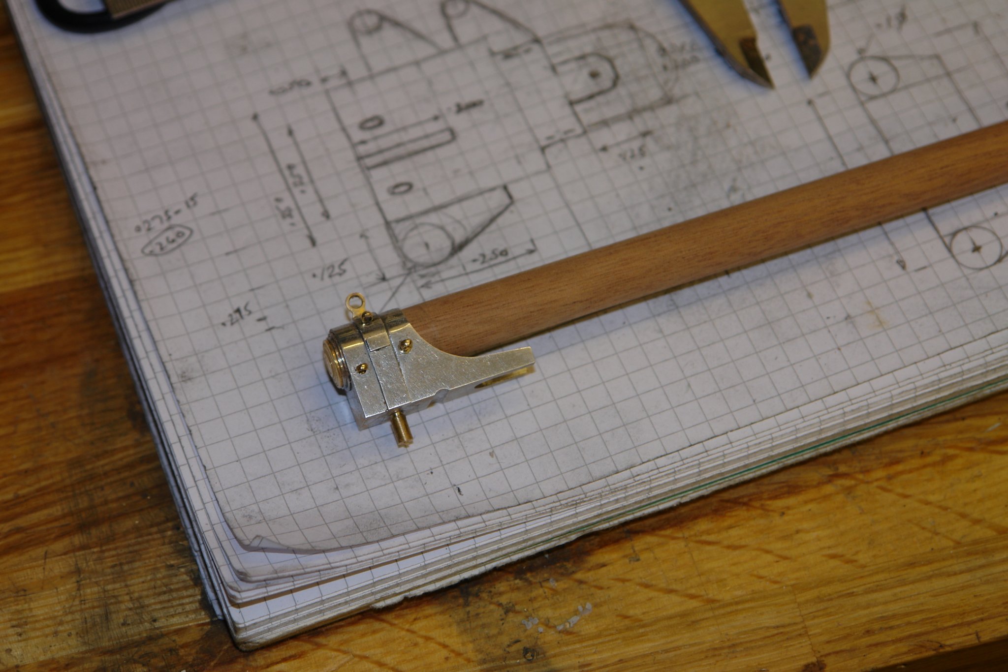
On 11/20/2020 at 1:00 PM, KeithAug said:
Thank you Steve, Gerrt and Allan. I do think finding a way of doing something is the most fun part of the hobby. Also Thanks to everyone who has left a "like".
I am feeling that my work is a bit unstructured at the moment as I dot about finishing parts of the deckhouse. Sorry!
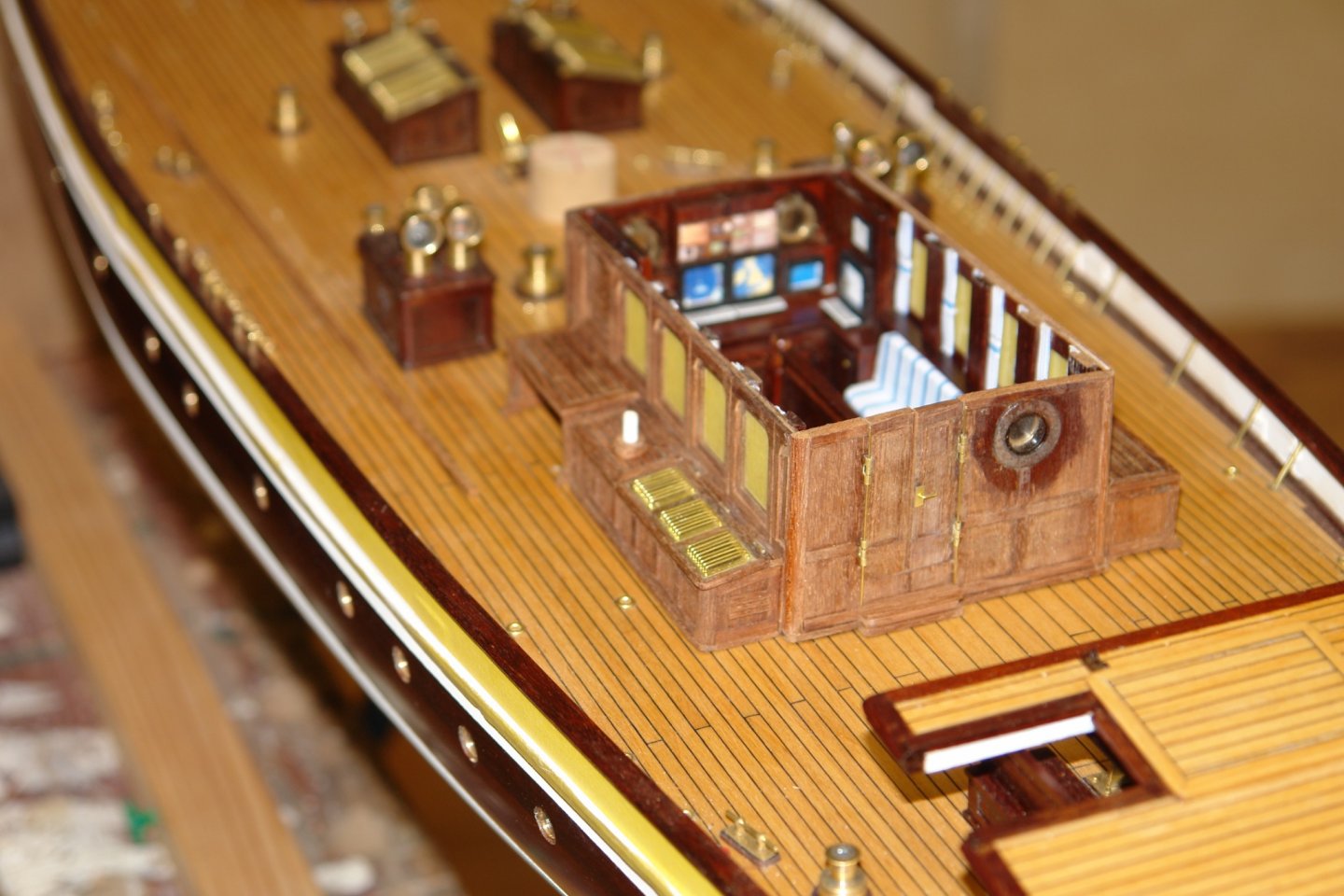
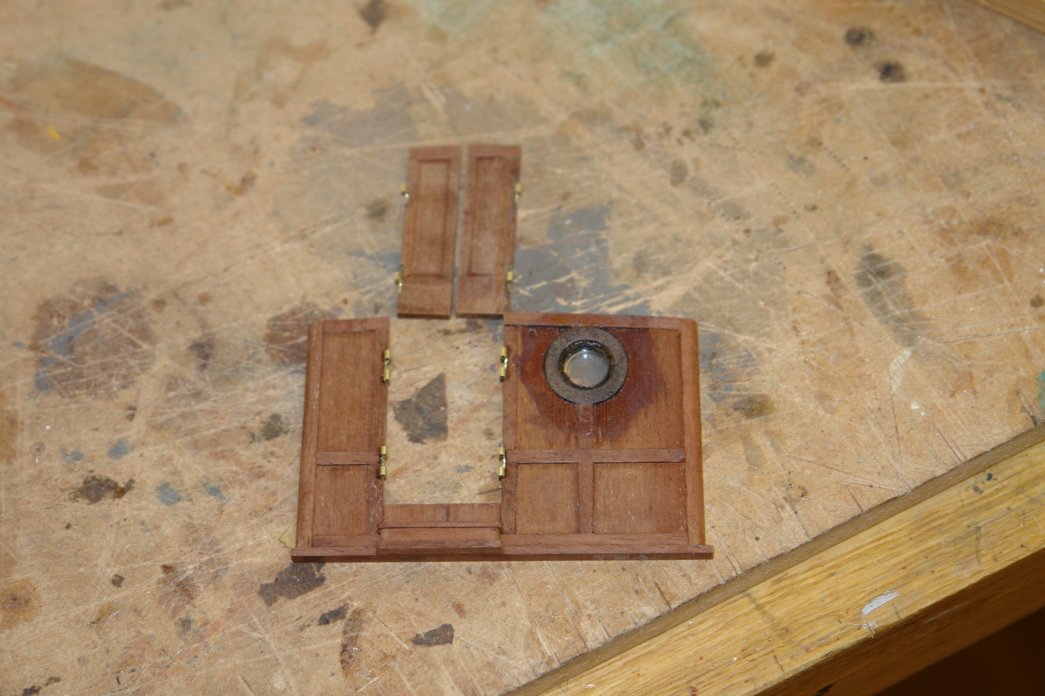
I thought the time had come to finish the back walL I cut out the rebates for the door hinges and glued them in place. The tricky bit was ensuring the correct alignment of the 2 parts of each hinge

I made the door plates for the door handles and bent a piece of wire to form the handle. The wall was then glued in place.
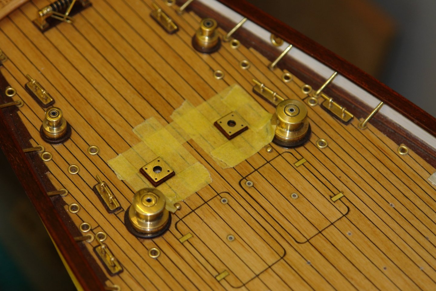
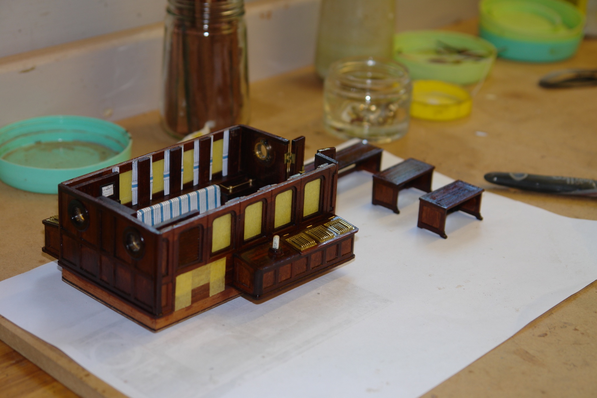
The door hinge pins are temporarily replaced by a couple of thin wires. I have also drilled the port wing bench and inserted a dowel (white) to take yet another cowl vent.
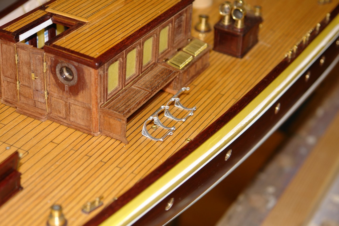
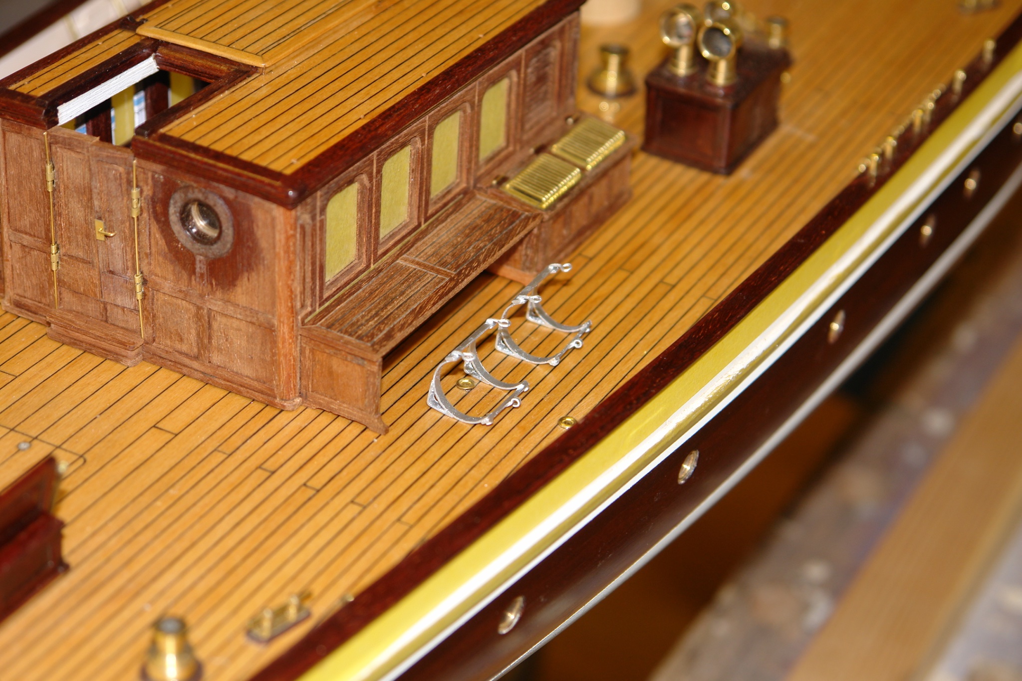
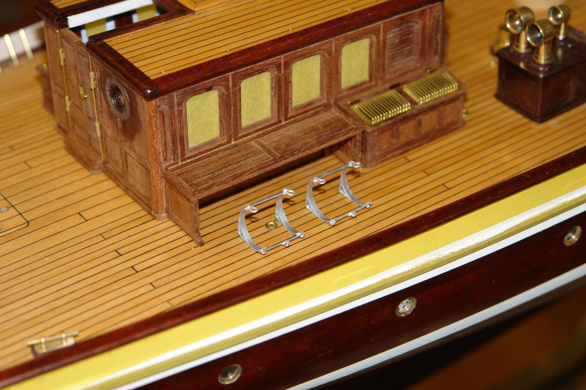
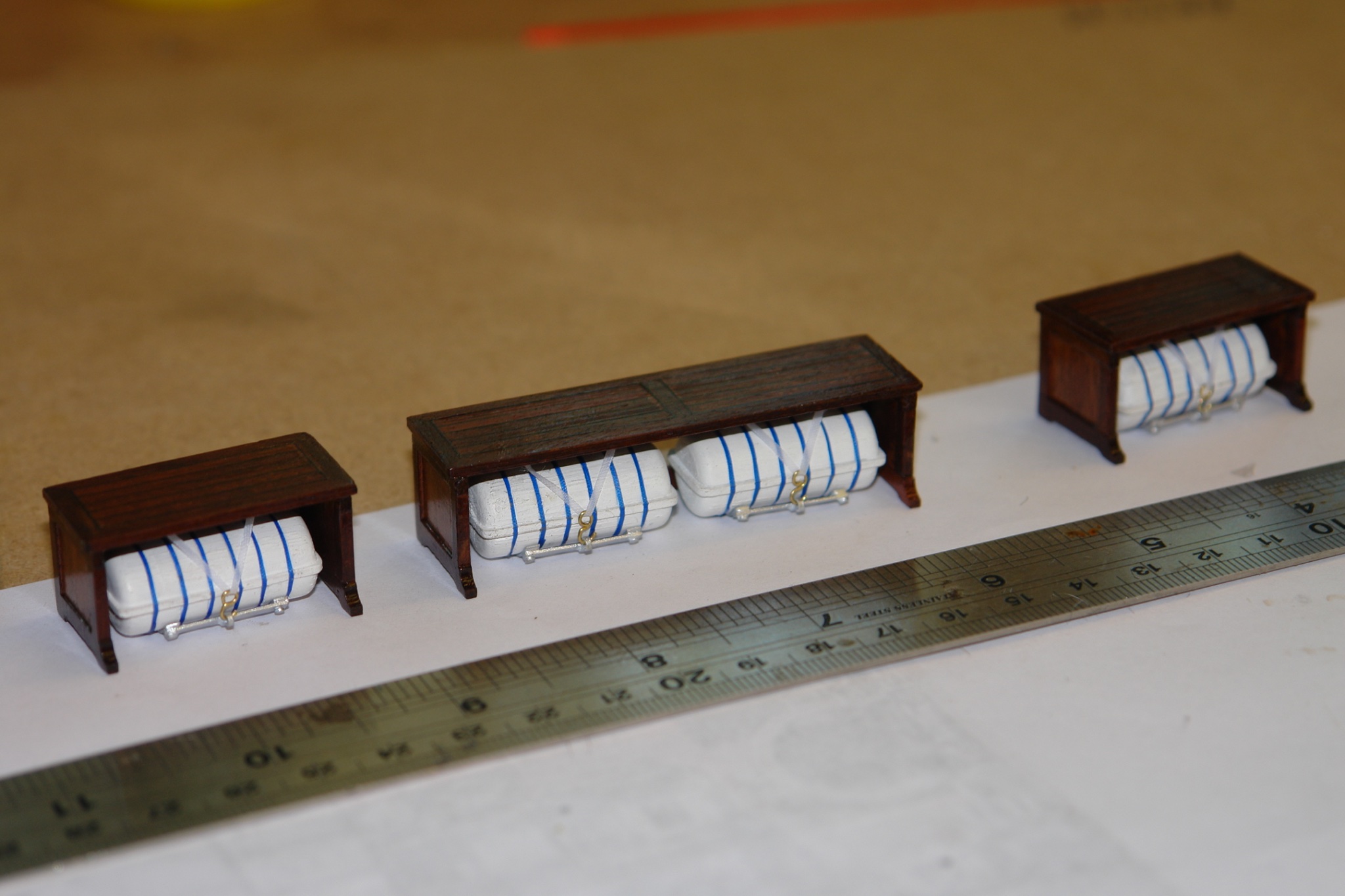
I then painted the raft cradles silver and placed them on the deck besides their covering bench. I test fitted the roof and did a bit of light sanding adjustment to make it fit. The roof and bench are not yet glued on.

I then took the various beck house components off the hull, masked off the unpainted areas and started the process of painting the parts with Poly.

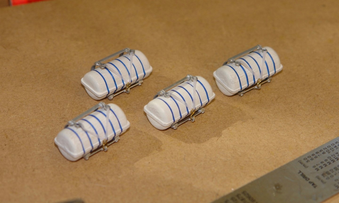
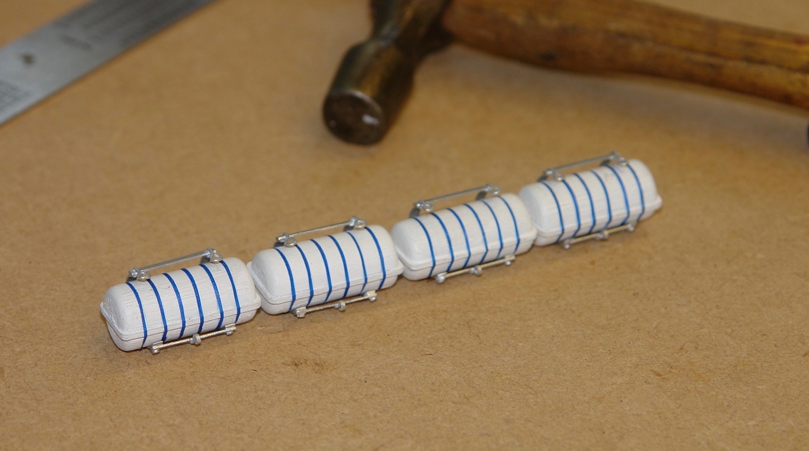
While drying I went back to the rafts. They were given 3 coats of white paint before case straps were added, Made form ripstop tape cut .010" wide with a sharp craft knife.
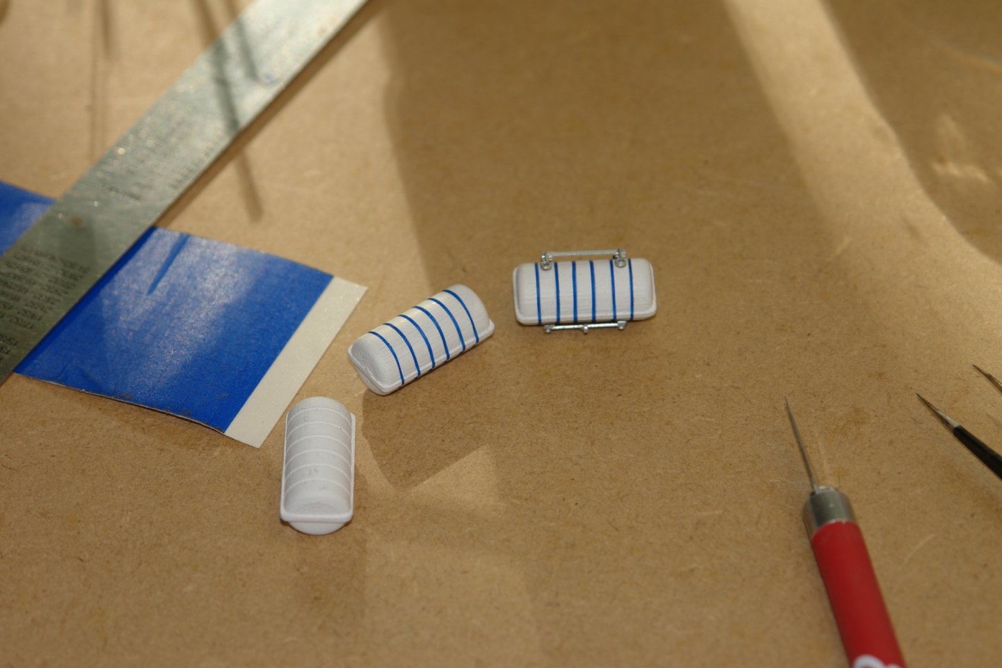
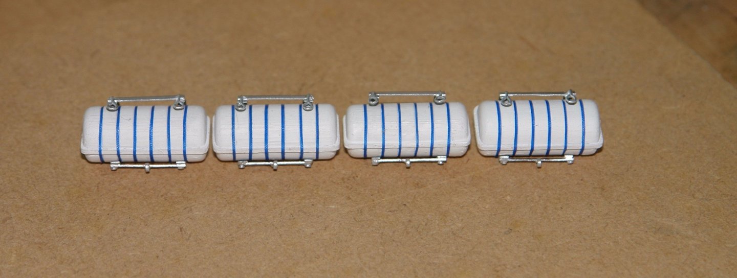

I then cut the cradle retaining straps and mounted them (a bit translucent and hence difficult to see).
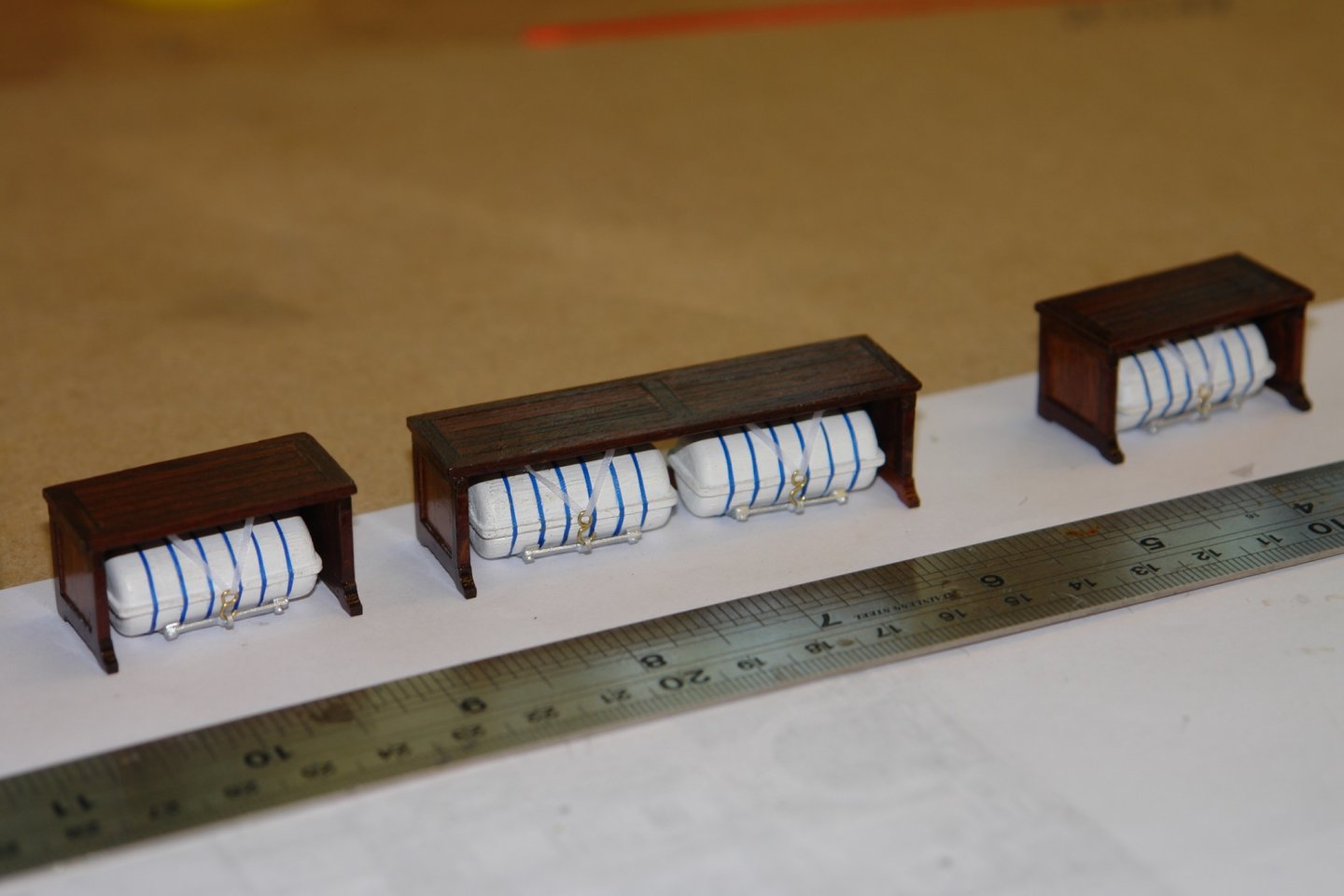
I was eager to see what they looked like under the benches.
Your skills are amazing! I am truly amazed by your attention to detail and ability to solve complex problems.
-
Another side note, approximately a year later I was on e-Bay and ran across the blueprints for the 24 lbs. Deck Cannon for the Constitution. Again it had been drafted by Harold Underhill and had the correct "Sheet and Build Numbers" and was only $25.00 with free shipping. I went ahead and purchased a copy and when I compared both the demesions where the same for both the carriage and barrel. I cannot explain it, maybe the poundage is a reference to only the shot fired or amount of powder used? I never looked into it so I don't know why they are identical in demesions.
Maybe someone here will know.
-
Your progress is amazing along with your skills. Im looking forward to future posts.
A little off topic, Many years ago I was trying to find out if there were blueprints of the Constitution's 32 or 24 lbs. Deck Cannons. I was looking to scratch build one using "Apple Wood" ( I was planning on replicating the cannon without paint instead using wood stain and semi gloss poly ) and the cannon barrel out of steel or brass. I called the shipyard where the Constitution was being refurbished at the time. Now remember, these are the people who are restoring the ship. Well I went through several people, from the secretary to the guy in charge of the refit. Finally the next day I recieved a call back from the historian on the site. He had received my request and had searched the archives and could not locate any blueprints related to the deck cannons. He then suggested I call the National Archives in Washington DC. Well I went online and went to their website and tried every which way to talk to an actual person but it seemed like a dead end. Then the gentleman historian called me back and told me he had located the name of the Naval Architect who had drawn up a set of blueprints for the Constitution almost a hundred years ago. His name was Harold Underhill and he was from England.
Well he got me a number to the archives in England where his US Constitution building blueprints were located. I called them and sure enough they had the blueprints and I cannot recall how much it cost me, maybe $50.00 but 4 or 5 weeks latter they showed up. I recieved one sheet of drawings for the 32 lbs. Cannon. I was amazed at the quality of the copy and how much information was on just one 24" x 36" sheet. I ended up building two using steel and apple wood with steel hardware and scale tackle, the scale of the drawing at 1/2" = 1 ft. the barrels were a little over 10" with a bore of 1/2" , If I was brave enough I probably could have used regular. 50 cal. black powder bullets and triple f powder and fired them. I would post a picture but unfortunately I do not recall where my build file is, when I locate it I'll post some pictures.
Sorry if this was off topic, I thought maybe you enjoy learning that the blueprints for the US Constitution are located in England. Oh by the way the original drawings were destroyed during the War of 1812 is what I was told.
Respectfully,
Tim
-
On 11/30/2020 at 1:42 PM, KeithAug said:
Allan, Keith Druxey. Pat and Gary- thank you all for your comments, you are all too kind. I quite often look at other modellers work and think I wish I was that good. Perhaps it is all a matter of perspective.
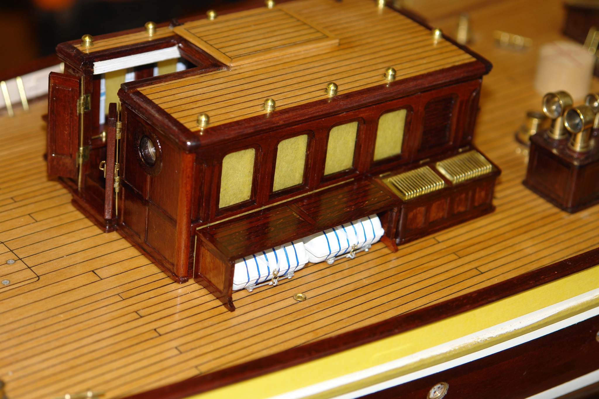
Not much of an update this time - just to confirm that I finished the deckhouse and can now move on to something else.
The benches were glued in place and the life rafts were glued beneath them.
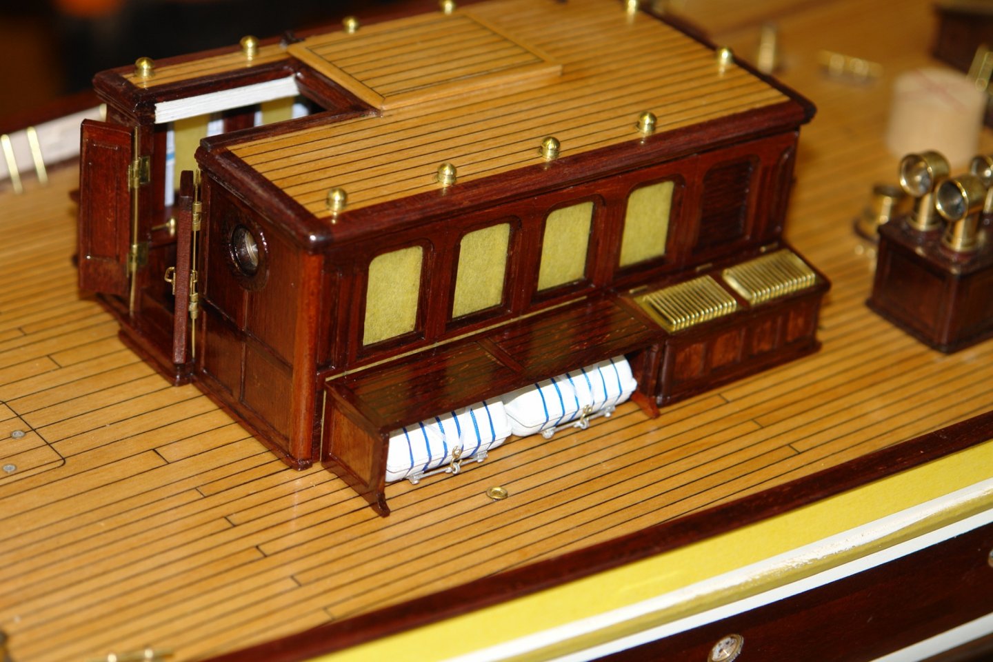
I then made the brackets for the planks that fit across the front of the rafts.
The planks were then installed making the raft cradles almost impossible to see from most angles of observation. With the poly application finished I was able to remove the masking tape from the windows.
The ships bell was mounted.

The penultimate vent was then put in place.

The wires holding the doors on were removed and replaced with hinge pins.

Apart from a good dusting the deckhouse is complete and now I will have to decide where to go next.
Bravo ! Excellent Work Sir !
I'm not sure if this has been suggested elsewhere in this thread, but have you ever considered putting together a "Germania Nova Build Log" in the form of an actual book?
I can say that the information and details along with your "How To" sections is certainly worthy. If any thing, the 46 pages ( Im sure there will be more in the future ) in this thread alone with comments, pictures and suggestions and your .pdf files would make a excellent book.
I truly believe a book or even a "E-Book" would sell easily. I have a fairly good selection of printed "How To" books on everything from planking to setting up rigging. I have also every book and e-book I could find on R/C Sailboat construction. Unfortunately most of the how to build books were published many many years ago and they all have terrible b/w pictures or poorly drawn diagrams. They are more or less written instructions, with nautical terms that if your new to the subject you will be hard pressed to understand how to accomplish your goal. The books with decent images and drawn profiles are more or less of completed models or of museum pieces.
I know nothing about publishing a book or what it entails but I have read or heard that with today's technology it is possible to self publish a book or e-book. Even if you just put together a .pdf file of everything you have posted here, maybe adding in additional comments or steps you had taken during the construction along the way and offered it up as "Free" with a "PayPal" link for donations I believe you would be successful.
As for a physical book, I am into "Astrophotography" and I am a member of a local astronomy club and many astronomy forums. I learned of many members who have taken their astrophotography images and had them put into book form. From what I can recall most had done this in order to give them as gifts. They even write about how a semi-gloss type paper is best for their images.
I'm just so impressed with your attention to details and your methods, I believe a book that is somewhat easy to follow with good images and line drawings would be a great benefit to the model ship building community.
A side note: I was looking up Germania Nova Blueprints and Deck Layouts on Google and suprise I found images of line drawings you have shared here.
It's just my opinion, your work is impeccable!
Respectfully,
Tim
- KeithAug, mtaylor and Keith Black
-
3


Germania Nova 1911 by KeithAug - FINISHED - Scale 1:36 - replica of schooner Germania 1908
in - Build logs for subjects built 1901 - Present Day
Posted
I curious if there is some sort of geared mechanism for turning the grouped ventilators in unison, because it doesn't appear to be enough room between a few of them to be rotated seperate. Or maybe all controlled from one location electronically.