iMustBeCrazy
-
Posts
976 -
Joined
-
Last visited
Content Type
Profiles
Forums
Gallery
Events
Everything posted by iMustBeCrazy
-
 At the rate you're going this might be too late but: On an open boat sand everything on the inside before fitting, sanding later is a pain. Dang, you just posted, I knew it would be too late.
- 23 replies
-
- 1
-

-
- boston whitehall tender
- rowboat
- (and 3 more)
-
Nothing a coat of paint won't hide (after a little more filler).
-
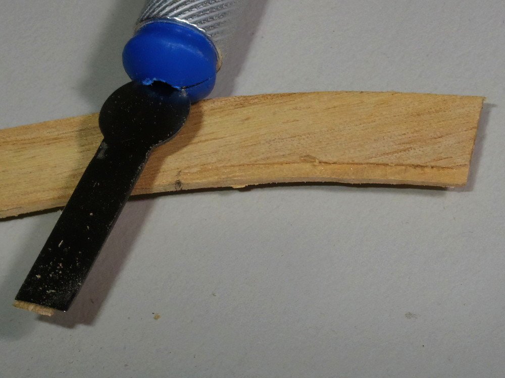
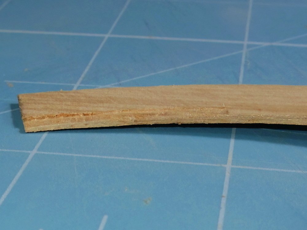
Well, I failed with the ply. It's just too stiff. So I sanded a piece of paulownia (which I used/am using on my Bounty boats and for everything except the bulkheads on Kitty) down to 0.65mm to match the ply and fitting it was a piece of cake. Paulownia is very like double density balsa. Once it's filled and painted no one will know.
-
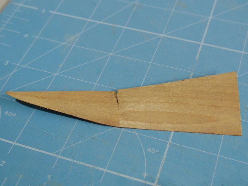
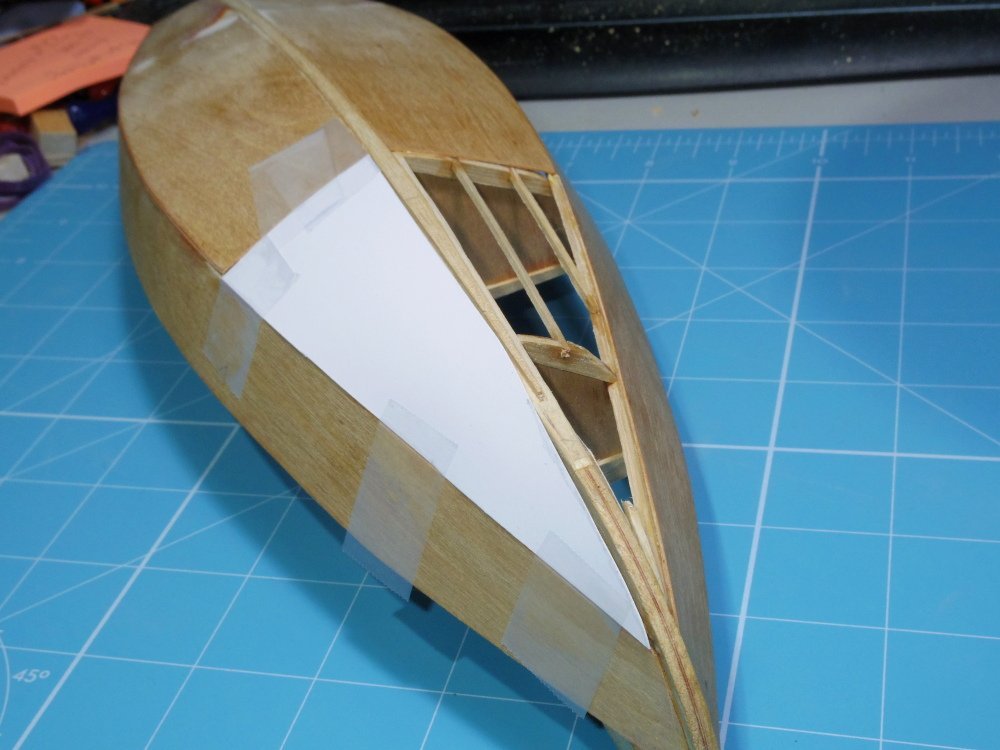
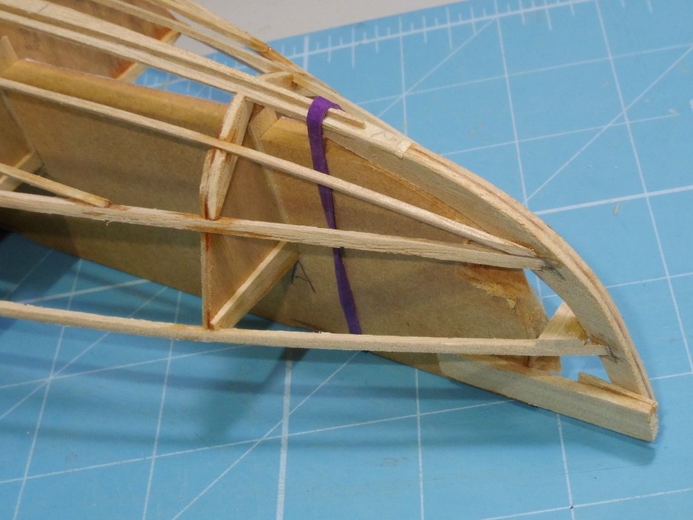
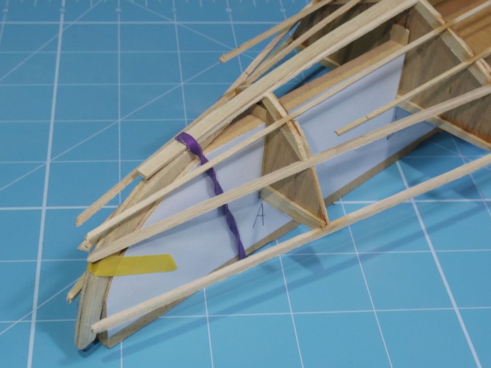
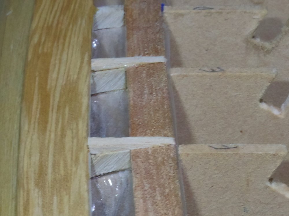
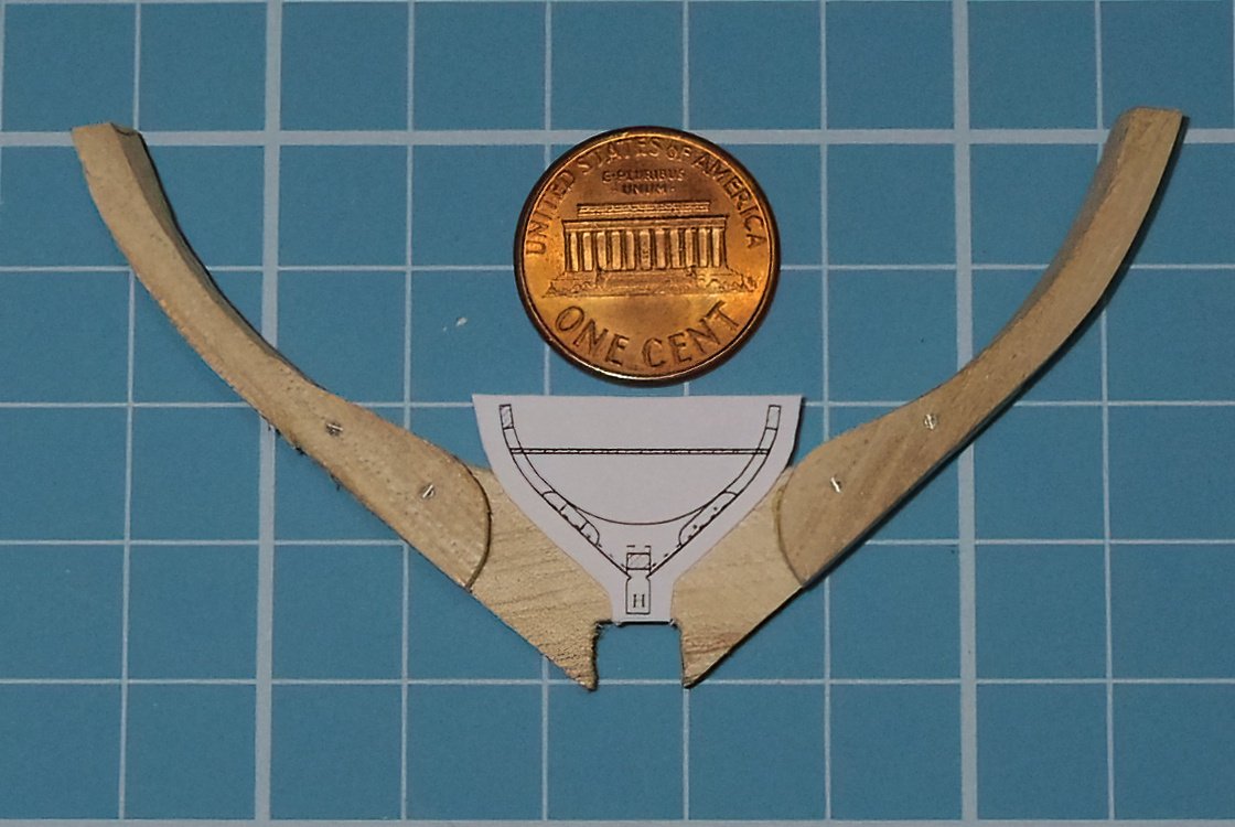
Well, as I expected the bow sections are a bit more of a challenge. Both the long edges change from overlapping the keel or side to a butt joint to the stem or side add to that getting the curve working and you can see it's going to be fun. The shape wasn't too hard, templated in card. And I think this will achieve the curves. It has been warmed with a heat gun but I do not know yet if it was warm enough. And yes, that's another stringer gone.
-
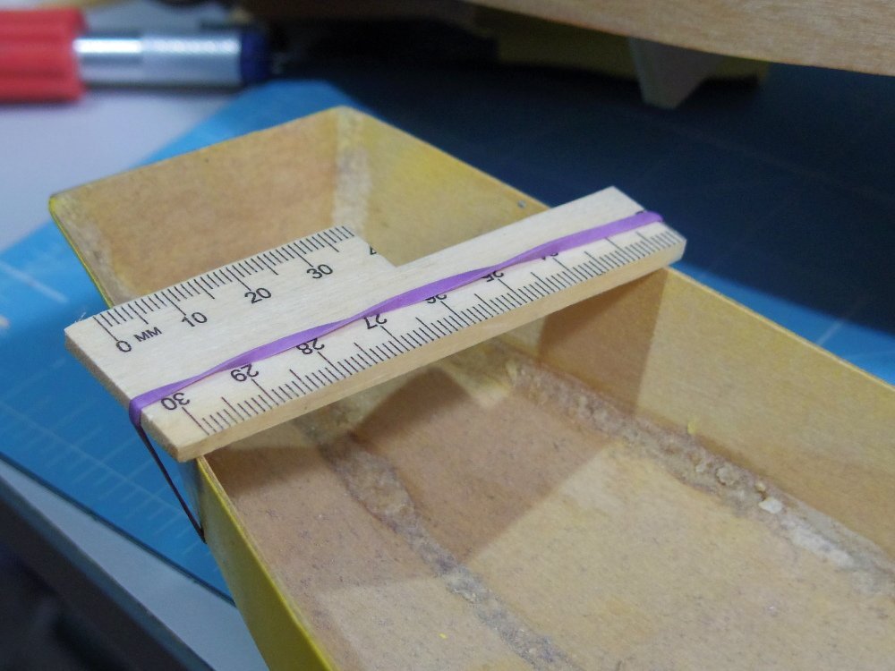
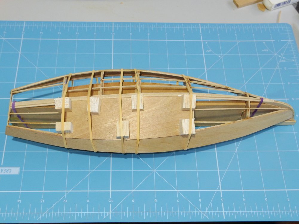
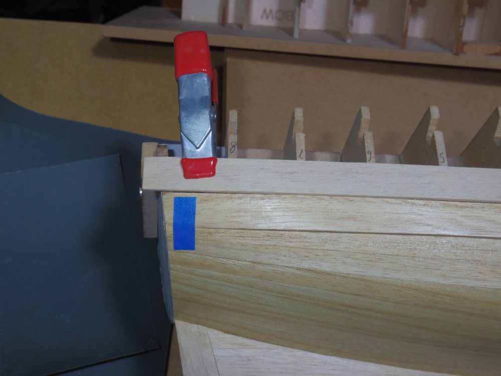
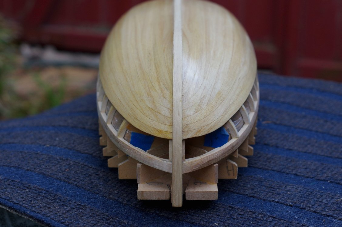
A rubber band and a piece of scrap wood will create a reference you can measure from. You can also square it up from one of the transoms to align things lengthwise.
- 72 replies
-
- 7
-
-
- Norwegian Sailing Pram
- Model Shipways
- (and 1 more)
-
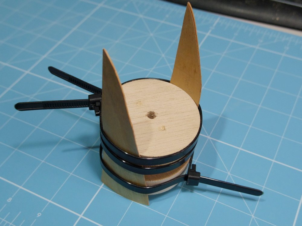
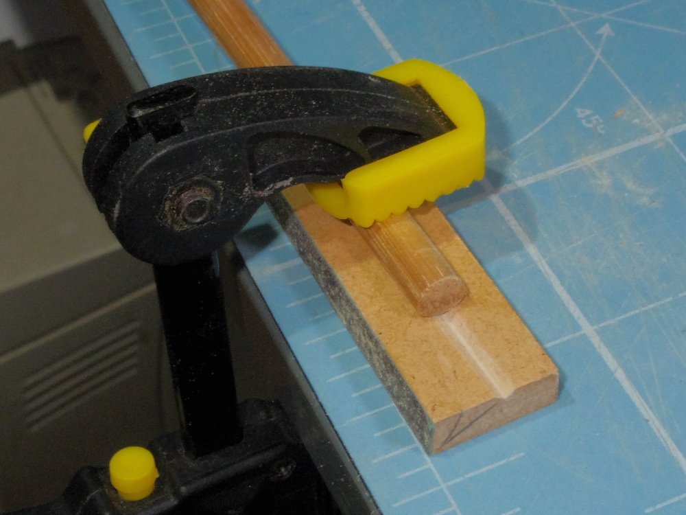
Make a 'V' block as shown, if the brass is too short put a bit of wood through it and clamp both ends.
-
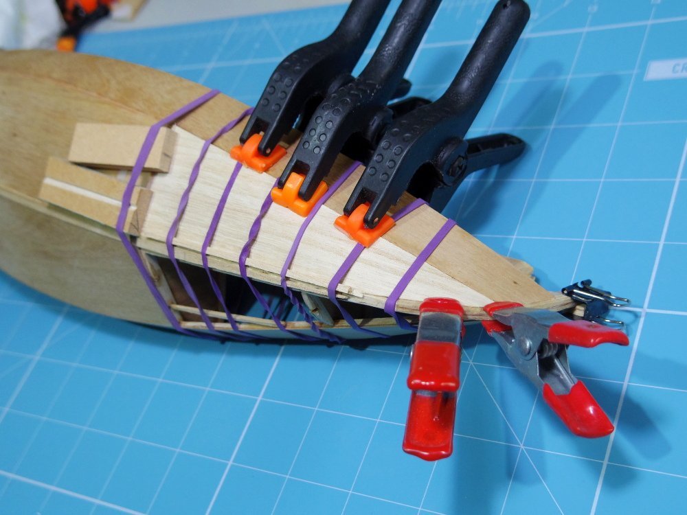
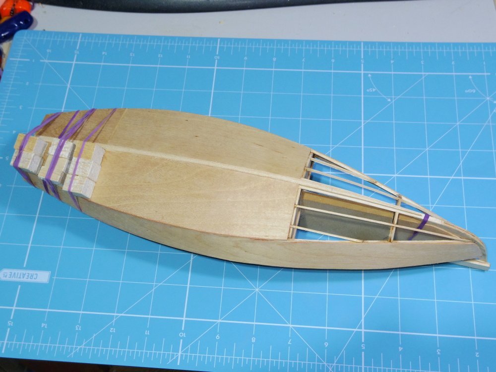
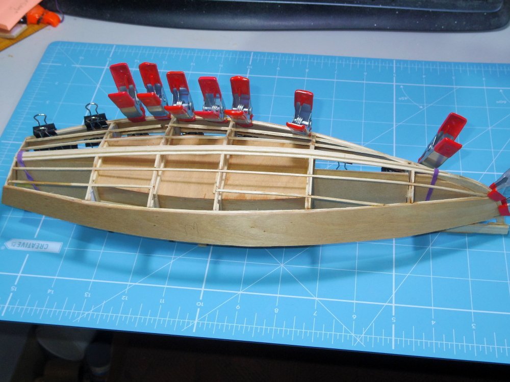
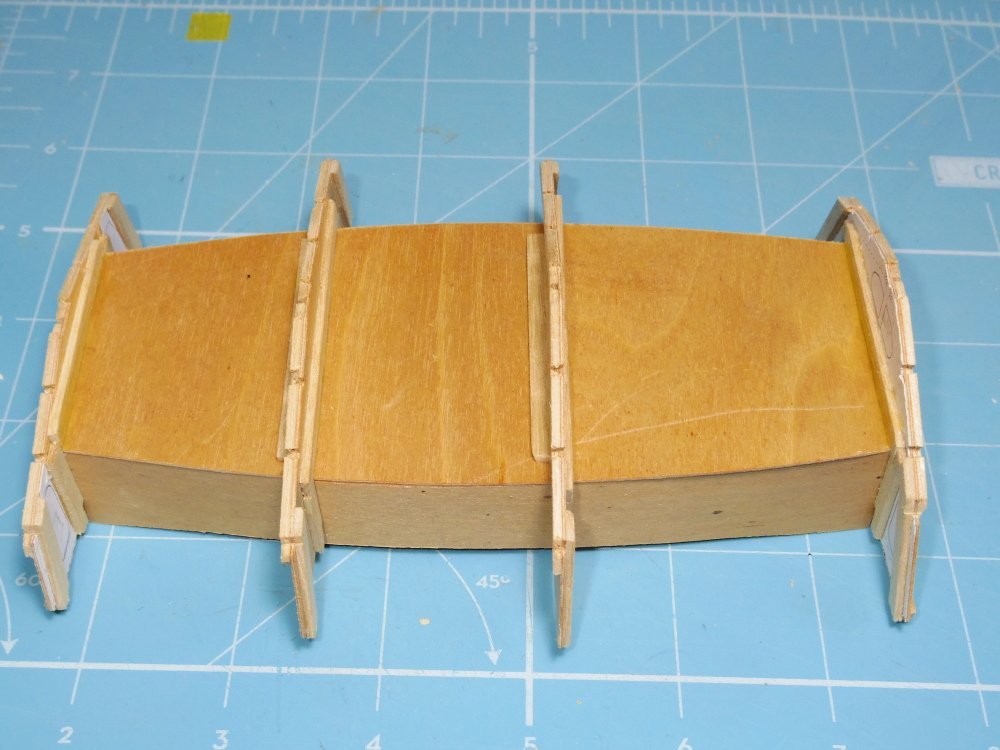
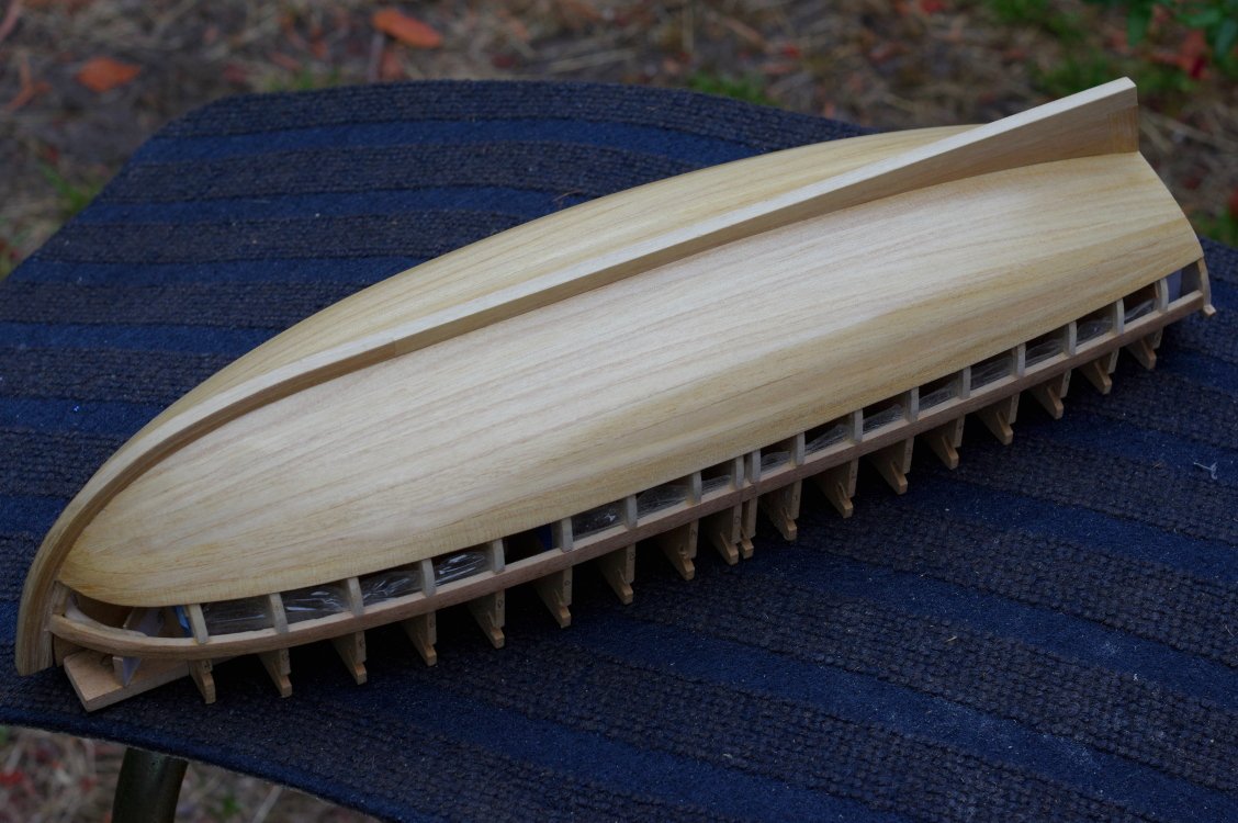
Moving along, most of the bottom on but I suspect the rest will be more difficult. Broke two more stringers but she is learning to fight back, she drew blood twice.
-
A different class John but designed in Sydney.
-
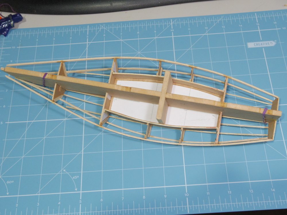
Chines and shelves connect to the stem and stringers connected to the chines. Sides fitted. Dang those stringers are fragile I've broken four or five so far, good thing I don't really need them.
-
Enough for today, chines and shelves made and fitted, errors corrected. Next I have to work where and out how everything attaches to the stem.
-
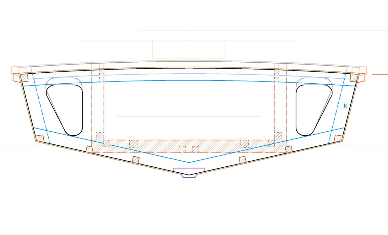
Glitch number 2 and 3, Frame E is an inch too tall, frame B is 3/8 too tall. Can still be fixed in-situ but I'm kicking myself.
-
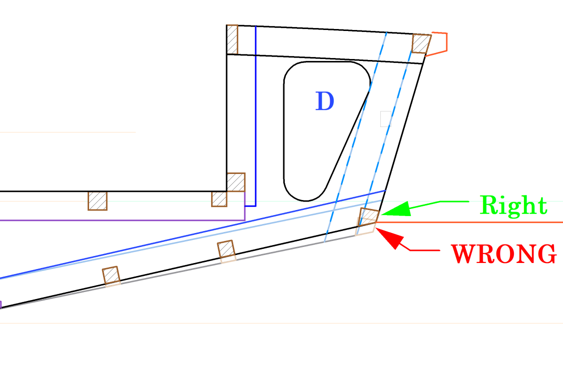
1st glitch, messed up frame D. Fortunately the fix will be hidden inside the hull, I just need to re-cut the notch for the chine and sand down the frame and stringers.
-
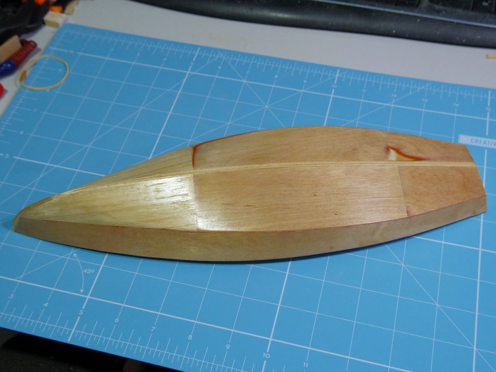
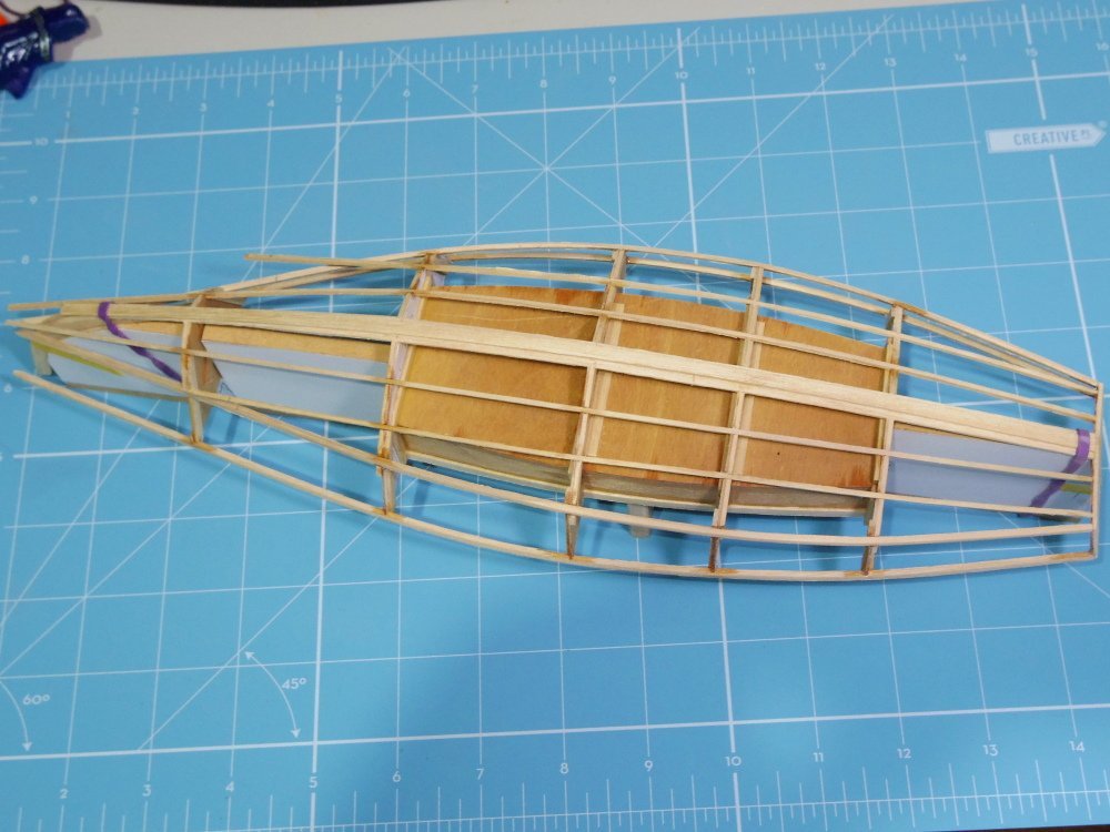
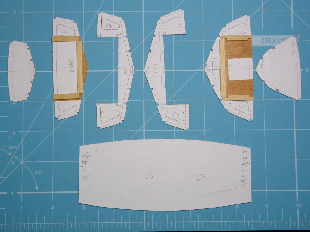
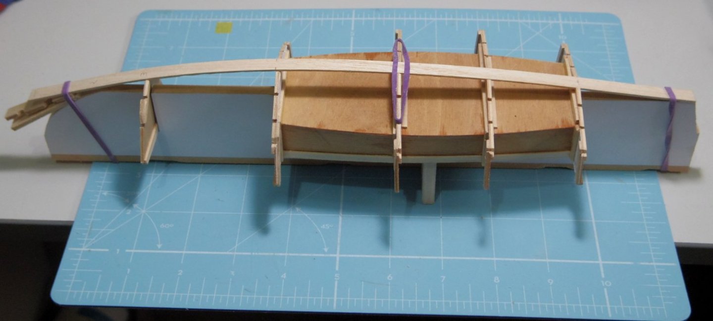
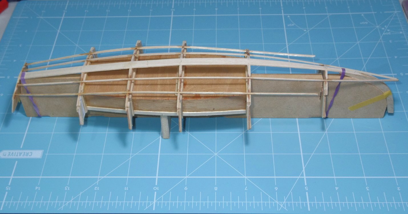
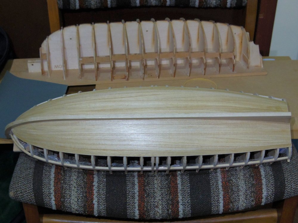
I think/hope my drawings are complete enough to build a model hull, only time will tell. Progress so far:
-
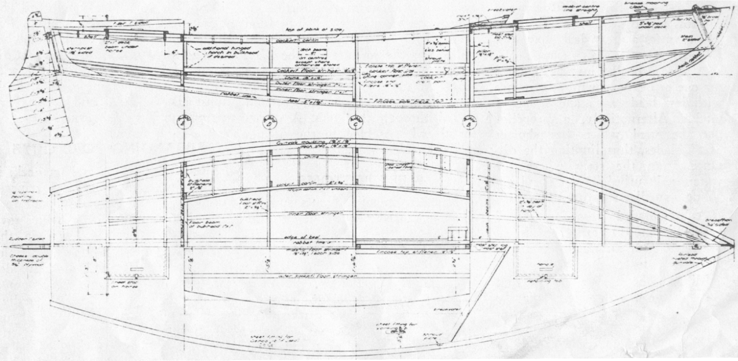
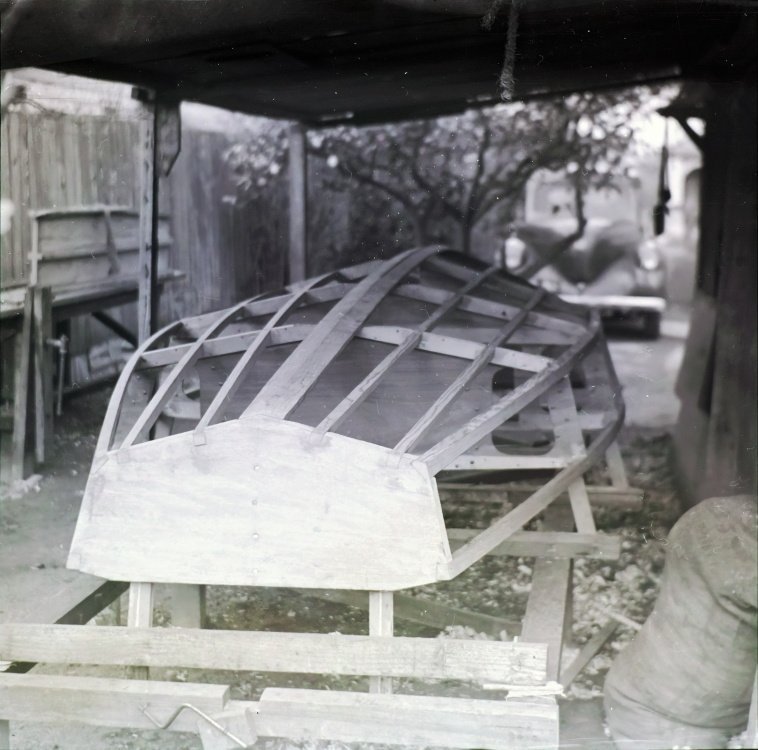
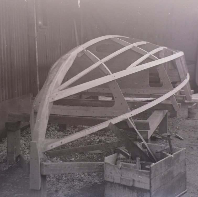
Something a little different. Hopefully this will be a quick build at least up to a painted hull, I only have until Easter to get that far. Some may be wondering why I'm not working on my Bounty launch. Kitty was built in 1949 by my father and three mates and was going to be my next build after the launch but the son of one of the builders will be visiting at Easter so the launch is on the back burner. I have been playing with drawings for a few months based on photocopies of photocopies of the 'plans' in a magazine, some incomplete drawings my father did in preparation for making a model, some photographs of the build and, fortunately, the materials list.

-
Thanks Tim, they seem to be. At this stage it's just a rough coating of shellac to seal it.
-
Unfortunately I stuffed up either my measurements or my gluing of the landing strakes and the sheers don't overlap the landing strakes properly. There should be a 1" (scale 1/16") overlap the full length but I finished up with zero overlap at E, F, G and at the transom. The stem and midships are fine. I Ummed and Ahhed for some time and finally decided to add some packers to make the sheer sit at the same height it would be if it overlapped and then when I fit the fender it will hide everything.

-
Ok, I'm back. I got some insect repellent in my eyes and couldn't focus well enough for close work even with magnifying glasses. Better now. Prior to that I fitted the landing strakes. These are clinker as mentioned above. This time I used a stepped rebate for the gains rather than the 45°s that I used on the small cutter. I glued depth stops to a pair of blades (you need a left and a right) and cut rebates going down to half the thickness of the planks. It worked well and was easier than the 45°.
-
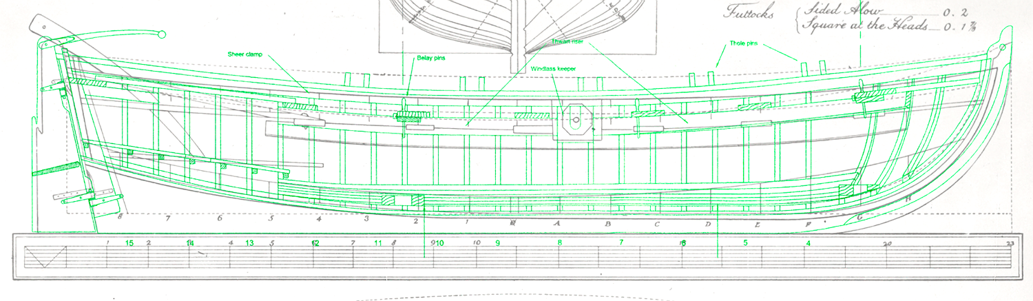
I'm not that old! The only real problem is you need to come up to the forward thwart. Some examples: https://www.rmg.co.uk/collections/objects/rmgc-object-66671 https://www.rmg.co.uk/collections/objects/rmgc-object-67761 Based mainly on the above and other contemporary models, the quarterdeck was likely solid (no gaps between planks), the foredeck either solid or a grating. Based on experience, the rowers need somewhere to brace their feet. Either raised floorboards or footrests. There will be exceptions.
-
I thought you were being a bit optimistic at 10mm diameter.
-
Thanks Tim, remember the tortoise and the hare. More importantly, take breaks while things are still going well.
-
The carvel planking is done, the next two (landing and sheer strakes) will be clinker/lapstrake so I'm going to have to change the way I think.
-
Not exactly but the RMG has her down as 1777.
-
Tim, have you seen the nice big clear Danish Archive copy of the Rattlesnake drawing? https://ao.sa.dk/ao/data.ashx?bid=31921156
-
Just a minor update, planking continues slowly. Although I've decided that the originals hull was most likely painted white I'm going leave mine natural with a coating of shellac, the timber is quite pale so it's 'close' to white and it will show off my work. And a better visualisation of Allan's project
-
Haven't we all? Taking a stab at it, from the comment about being short of white (paint) for the small cutter I'd guess all the boats were painted white (impress the natives) with the sheer probably painted in a colour that somehow matched the Bounty. Sometime before leaving Tahiti the bottom of the launch was painted with half pitch half tar (probably coal pitch (black) and pine (or Stockholm) tar (anything from light amber to dark brown)). The effect was probably a brown/black wash over the white leaving the launch rather dirty/shabby in appearance which would do little to impress the natives and may have increased the chance of being attacked. Model Shipways kit (green) v ZAZ7361 the drawing from the books: