iMustBeCrazy
-
Posts
976 -
Joined
-
Last visited
Content Type
Profiles
Forums
Gallery
Events
Everything posted by iMustBeCrazy
-
 Does anybody think this is wrong? To me it looks like that's what they intended.
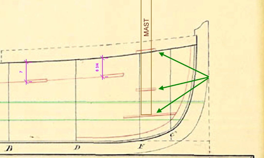
-
Allan, the only knowledge we have about the small cutter is that it was smaller than the large cutter and that it leaked, that's it. To that we add McKays assertion that it was 16ft long but where he got that from I do not know. So this is my best guess as to what she may have looked like, I think it's a good guess but I'm biased. Notched risers are shown on many/most drawings and make sense so I have included them. Thank you for your kind words.
-
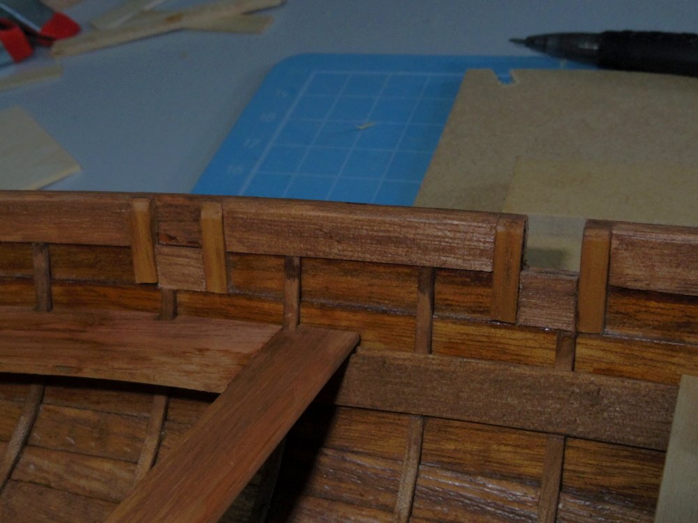
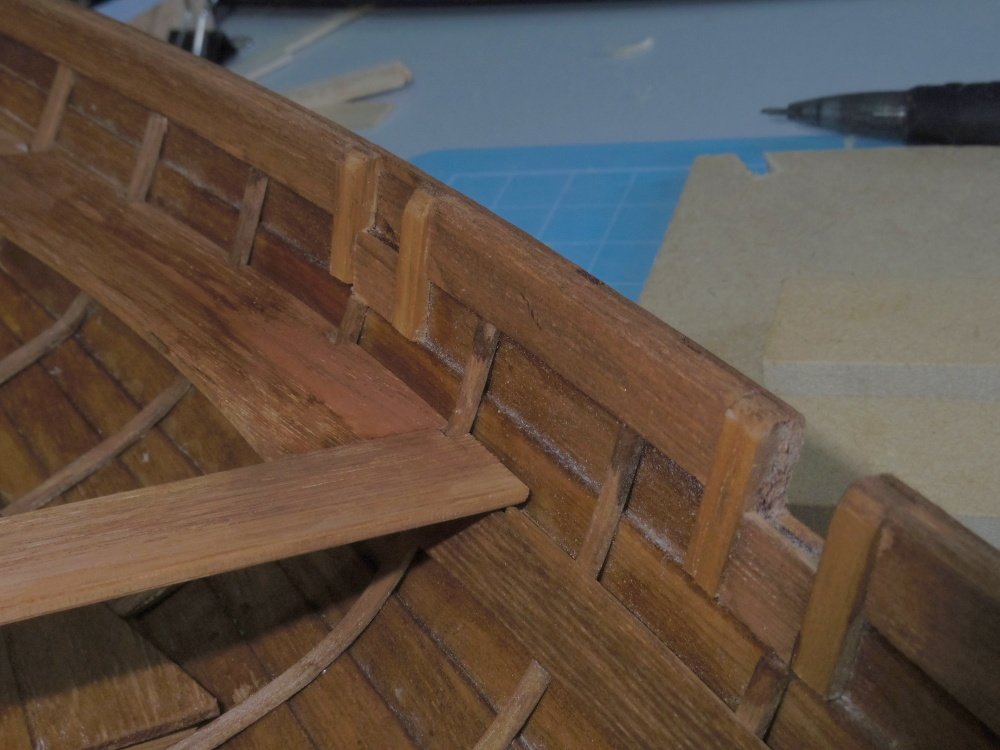
Quite happy with the washboard fillers, much neater. I'm thinking of painting the washboards black to break up all that brown. And will somebody remind me to dust and vacuum it before I clear coat.
-
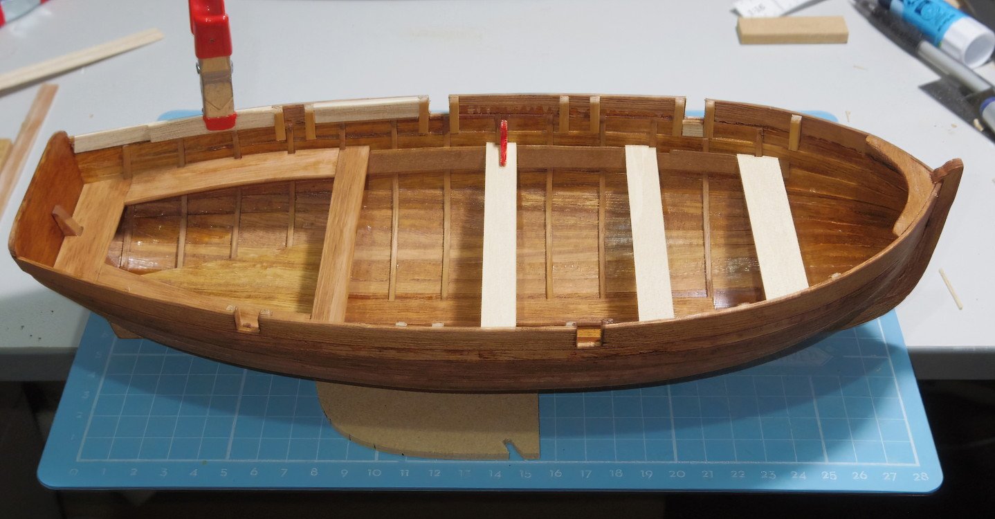
Some progress and playing with ideas. Fillers along the washboards to tidy up the end of the ribs and under the tholes. The quarter deck will get slightly rounded sides to fix that hard straight line.
-
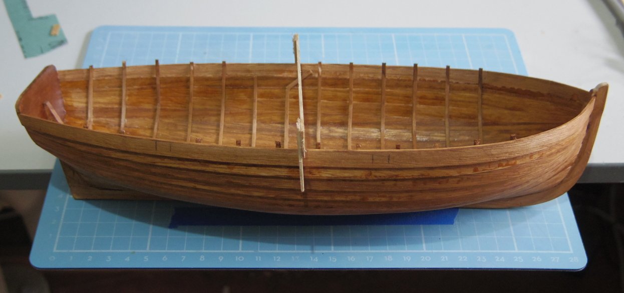
Looks a bit like a boat: And as light and fragile as an egg shell.
-
Getting close to cutting her free, just need to work out exactly how I'm doing the washboards:
-
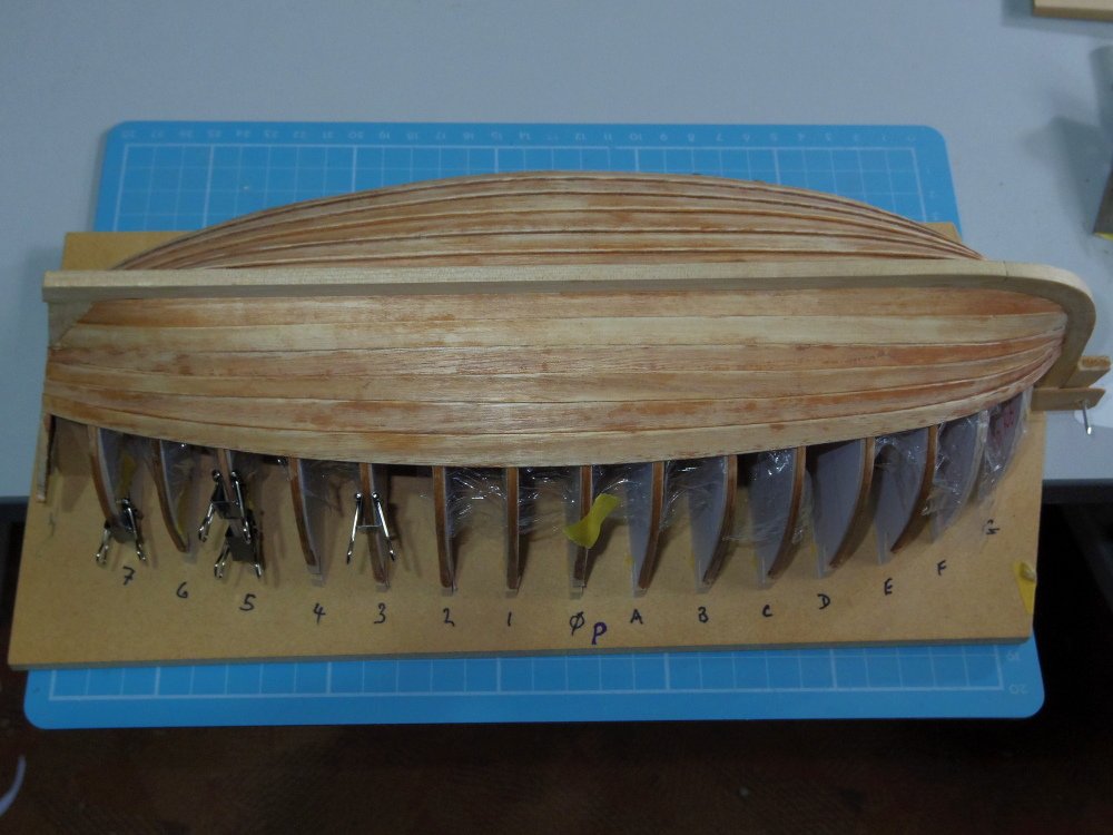
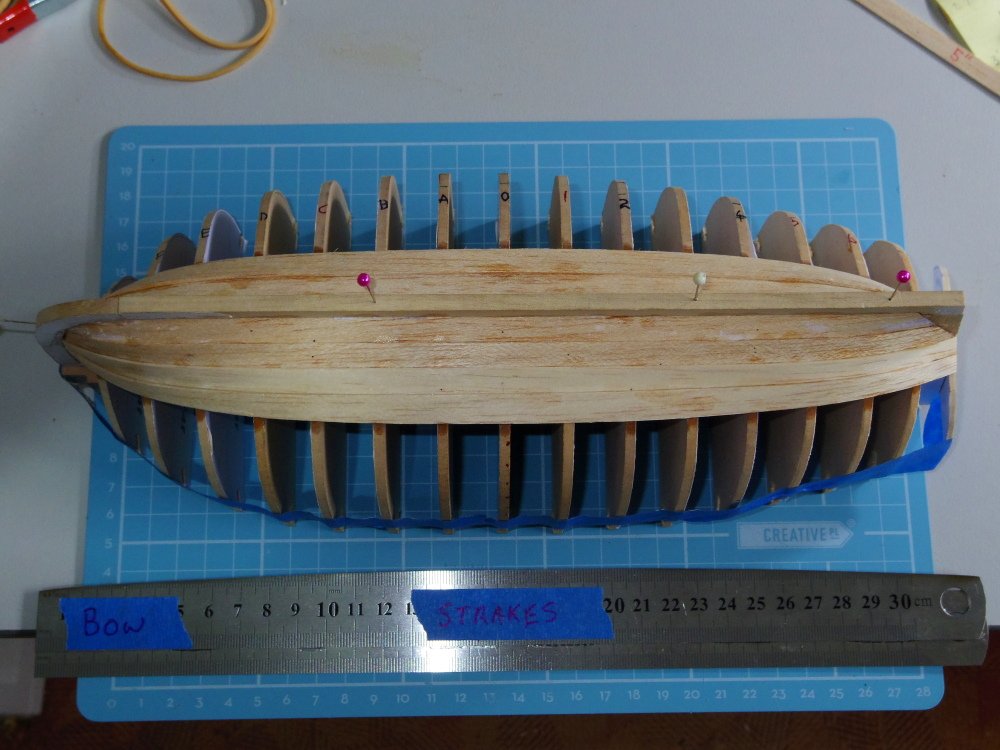
Progress continues on Deja Vu. A few more strakes added, just about reaching the point where you can see a boat there somewhere.
-
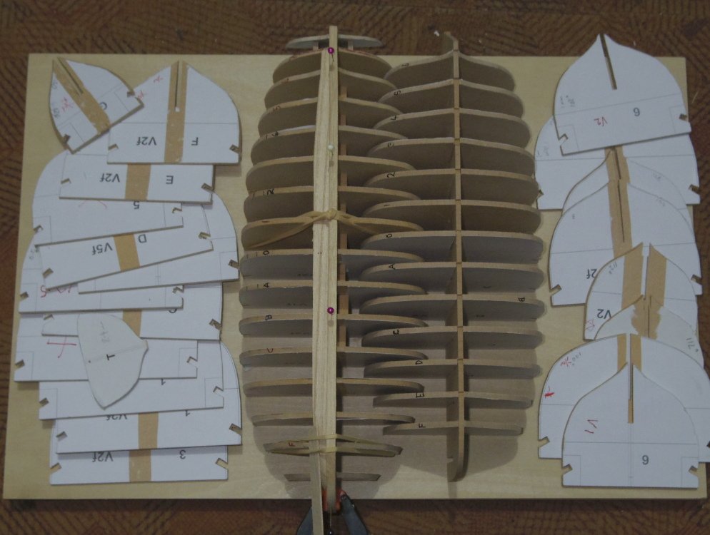
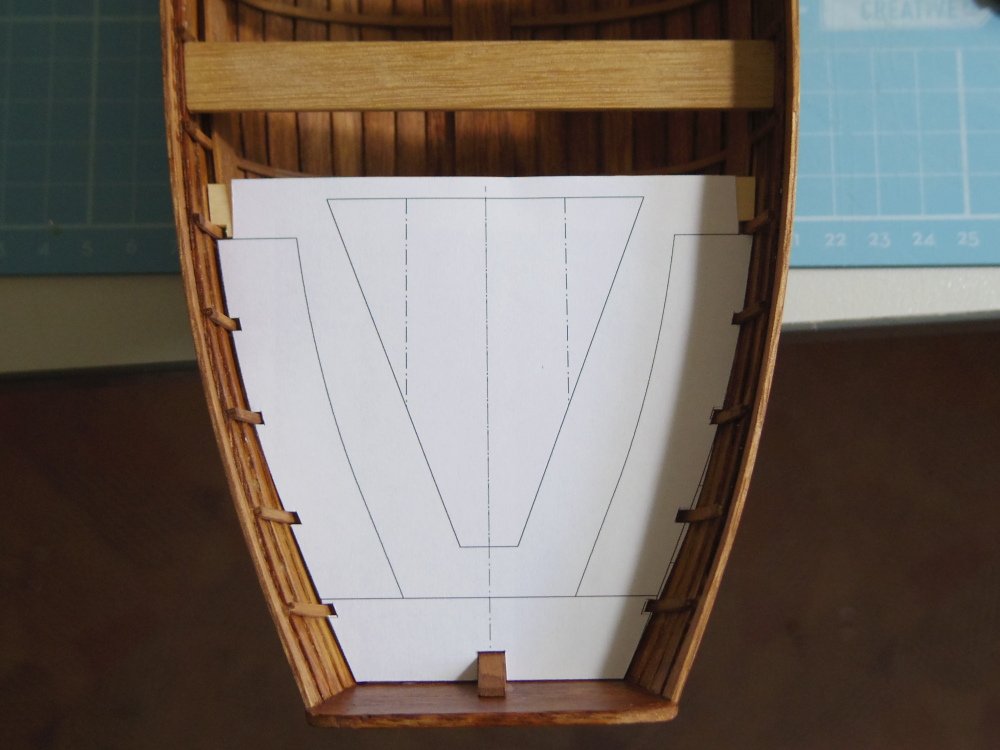
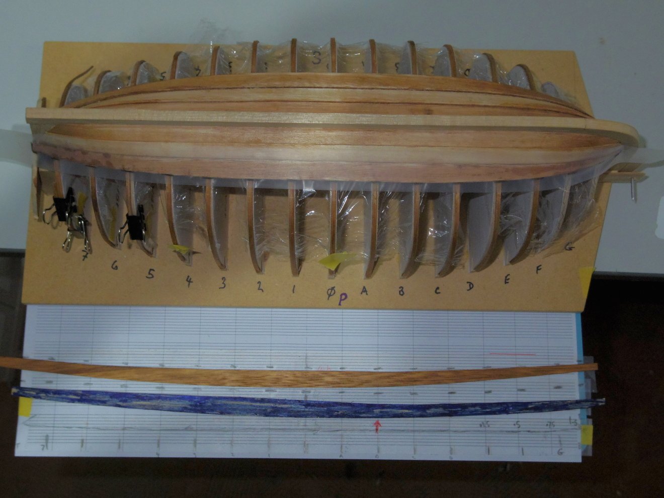
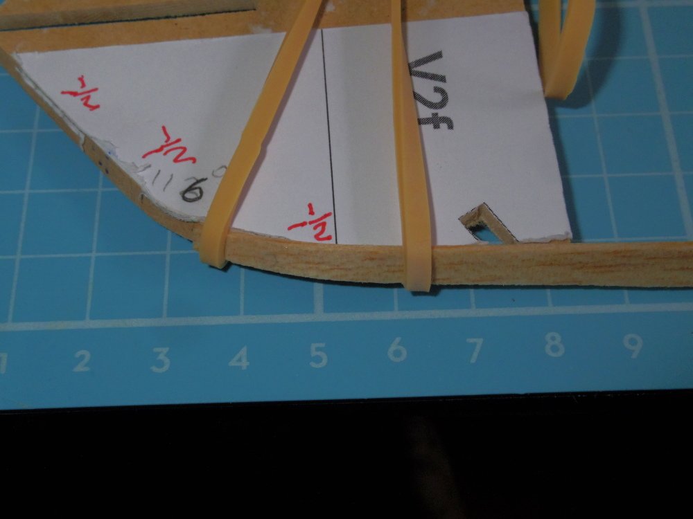
Work continues: The remaining planks are being spiled, that is shaped to the curve of the previous plank by measuring and cutting. It's a bit tedious. 1/ Scotch Magic tape is placed along the previous strake. 2/ Pencil marks are made of the edge of the previous strake at each station, transom and stem. 3/ The tape is removed and stuck on to a print of a homemade grid. 4/ The locations on the grid are transferred to the same grid in CAD. 5/ Adjustments are made allowing fore the strake overlap, 5/8th inch at the ends and 1 inch for the rest. 6/ A curve is drawn joining these points. 7/ Three new points are added below this curve at the transom, station 0 and the stem for the calculated width of the strake at those points. 8/ A curve is drawn joining these points. 9/ This is printed, cut out and test fitted to the previous strake (if it's not right start again Note in the pic that 4a (blue) has a kink at the red arrow and was rejected). 10/ Scotch Magic tape is placed on the board (sanded both sides) board stock and the printed strake is glued to the tape (the tape removes cleanly and the same printed strake can be use for the other side) 11/ The plank is cut to the share of the printed strake. Mark station 0 in some fashion. NOTE: The strakes are longer than the paper (A4) so continue the curves a bit further. 12/ Ditto for the other side. 13/ Both planks are stained and primed (interior side) with diluted PVA. 14/ Fit to the hull (sounds easy doesn't it).
-
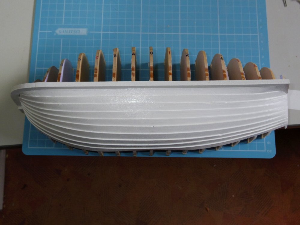
Progress is mostly in the right direction, but much much slower than with balsa and CA. Didn't use enough glue in places but that's being fixed. Broke one rib which would have been less of a problem if I didn't run over it with my chair before I noticed. Lucky I had a spare. The interior is being stained prior to each strake being fitted, the exterior will be stained properly later. I slapped some paint on the balsa version just for the heck of it:
-
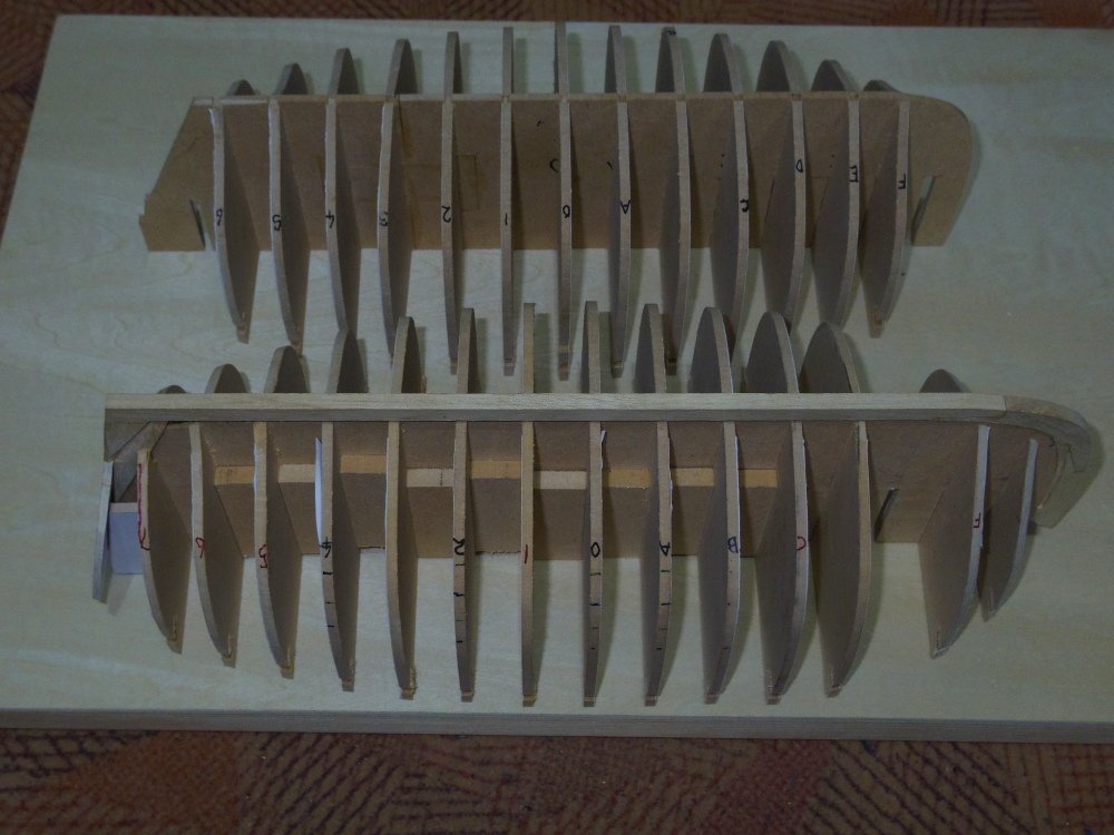
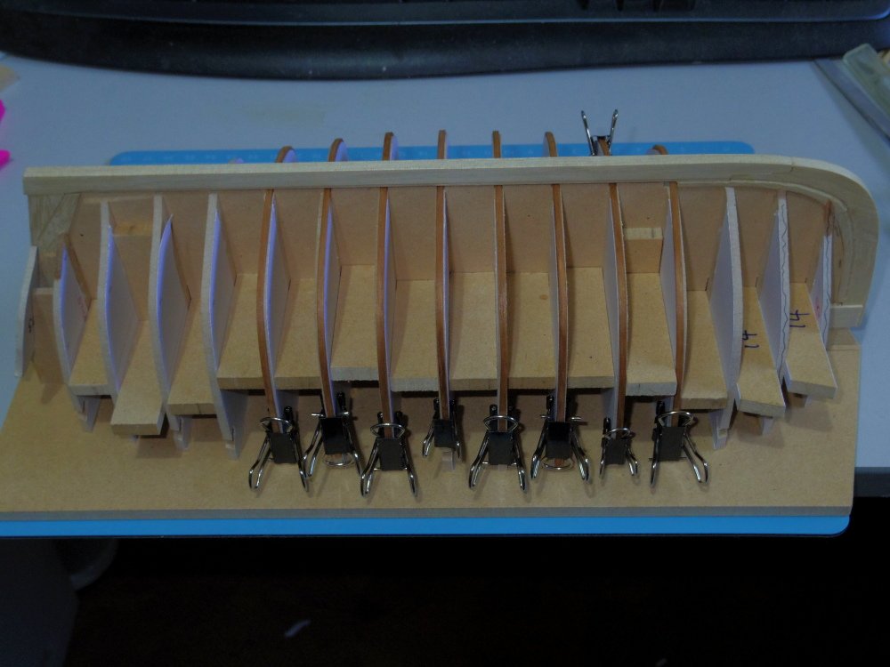
The test fitting showed a few of the moulds needed sanding so the the ribs didn't protrude above the false keel so that's been done, the ribs (except 6,7, F and G) have been glued to the moulds at their ends and to the keel. Ribs 6 and 7 will need to be glued to the keel first and then the moulds after that has dried. Moulds F and G have been made with false ribs and cant ribs will be fitted after the hull is remover from the jig. The cling film will stop me gluing the hull to the jig and hasn't caused any problems - yet, I will probably have to slit it between the moulds at some time to make clamping easier.
-
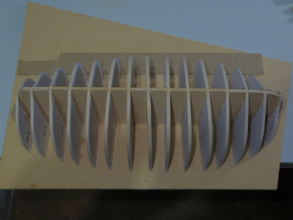
Third (and last I hope) jig is complete, assembled and glued to a board. Some other bits test fitted.
-
I think I'm going to have to name her the Deja Vu. I just have this feeling that I've been here before.
-
Progress continues, all the moulds have been tweaked in CAD, printed, glued to MDF and roughly cut out so I am / will be building what I hope is the final jig. The material for the ribs has been sanded on all four sides and the corners have been rounded off. They have also been stained (with a spirit based stain), steamed and bent or broken over the moulds of jig one ( yes I made spares). I haven't yet painted them with diluted PVA as I was thinking they may stick to the jig, but I was also thinking of covering the jig with cling film to stop the boat from sticking to the jig so I will probably paint the ribs anyway.
-
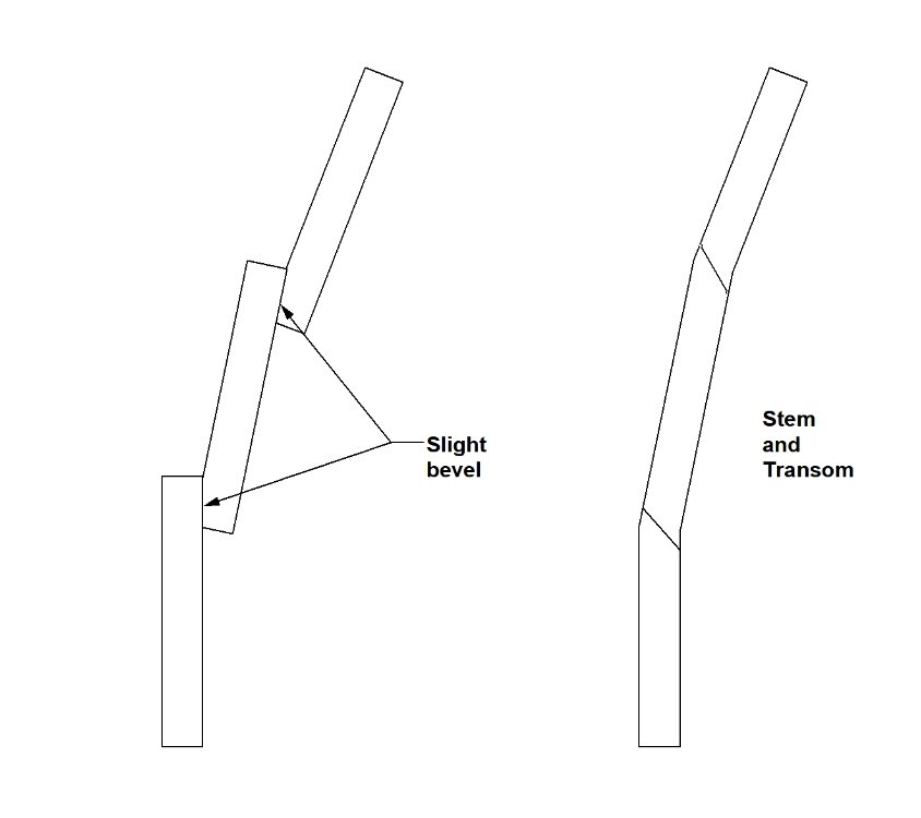
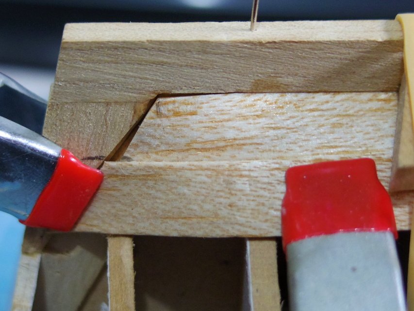
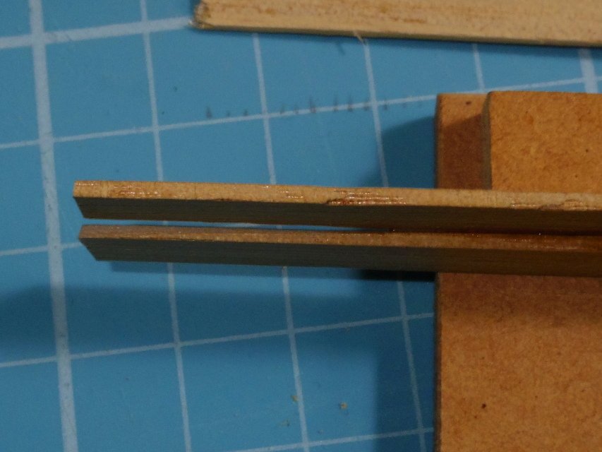
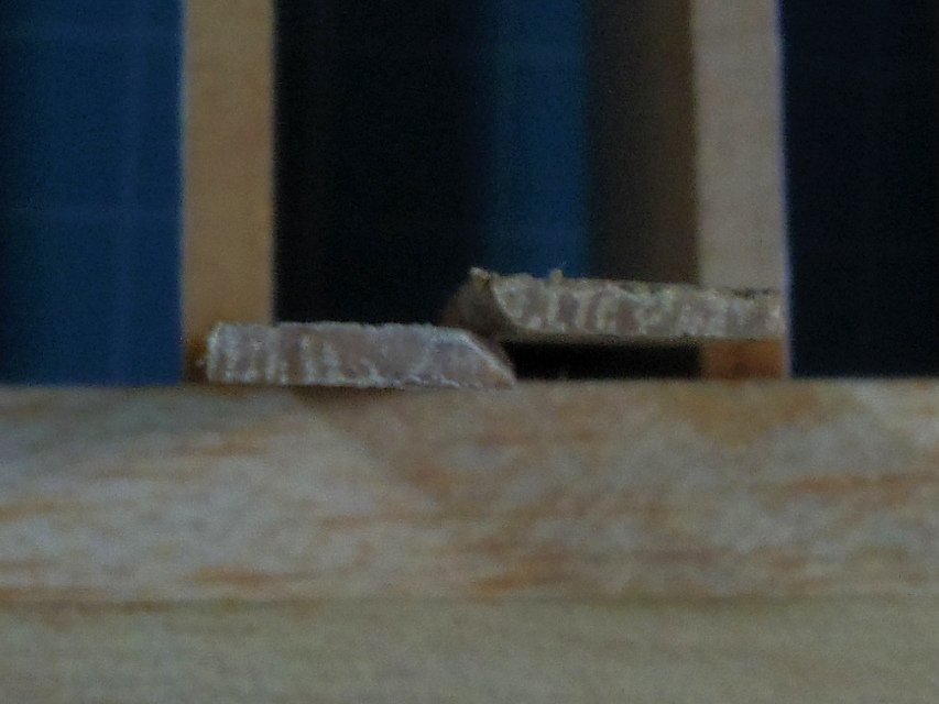
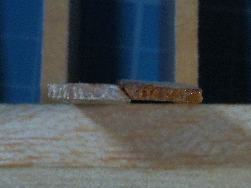
Allen, there is a very slight bevel the full length (or there is supposed to be), just enough so the overlaps sit together, then for about a foot each end there is a tapered or increasing 45 degree* bevel giving a carvel like join at the stem and transom but with 45 degree* edges. I still need more practice at that bit. * Nominal.
-
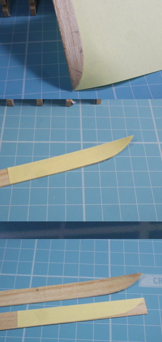
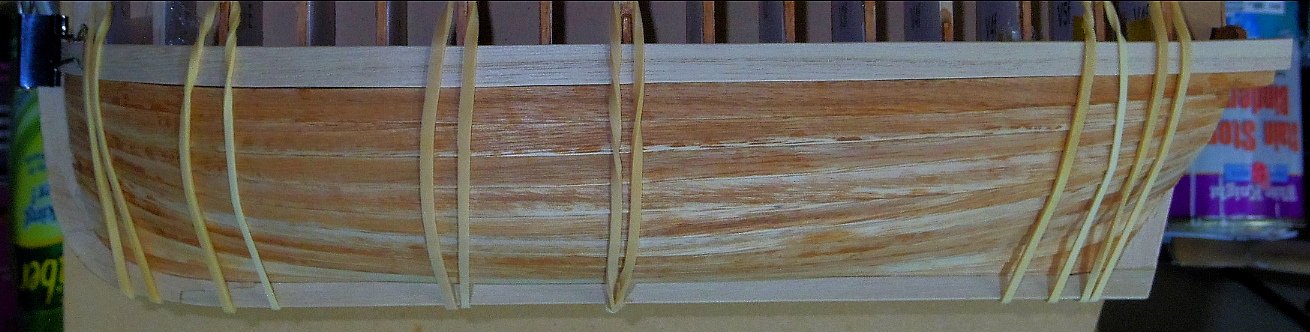
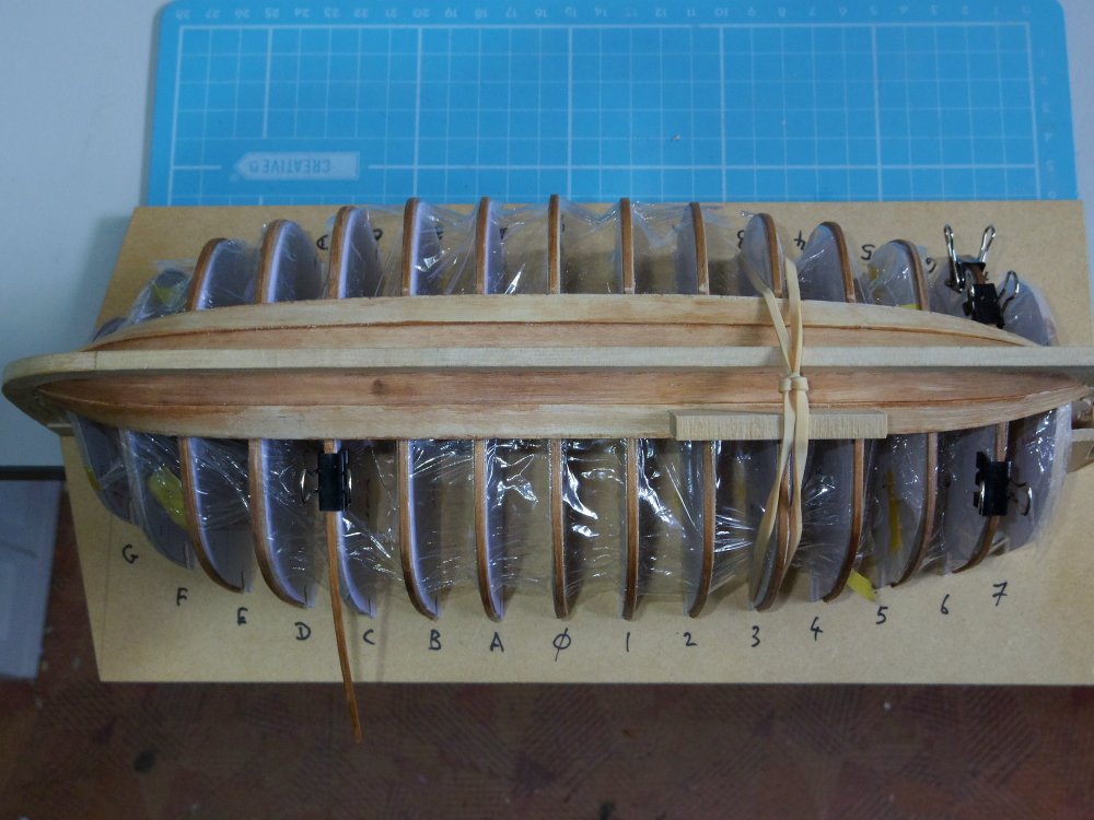
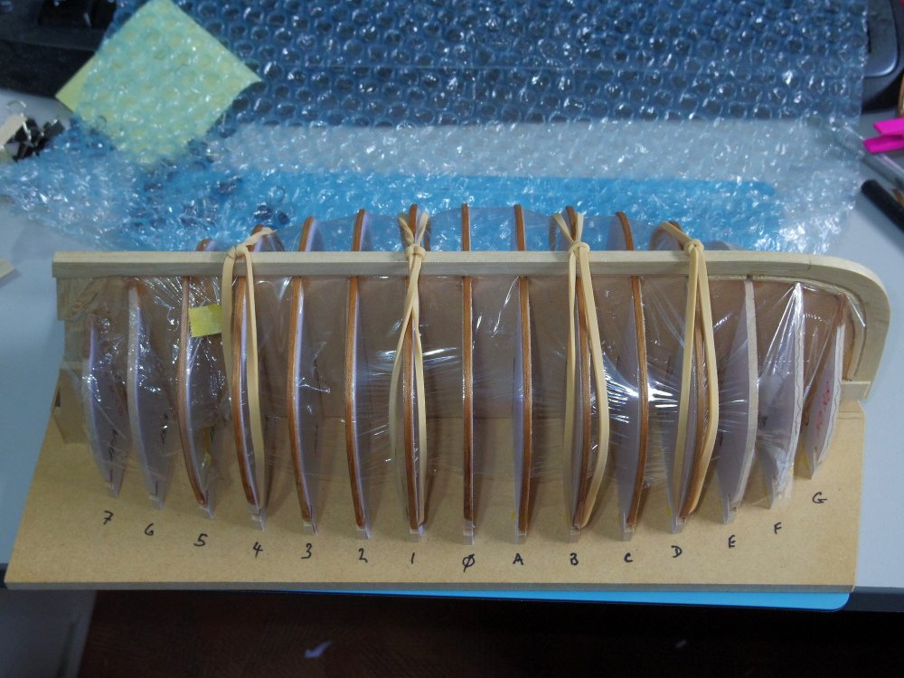
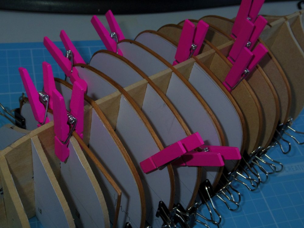
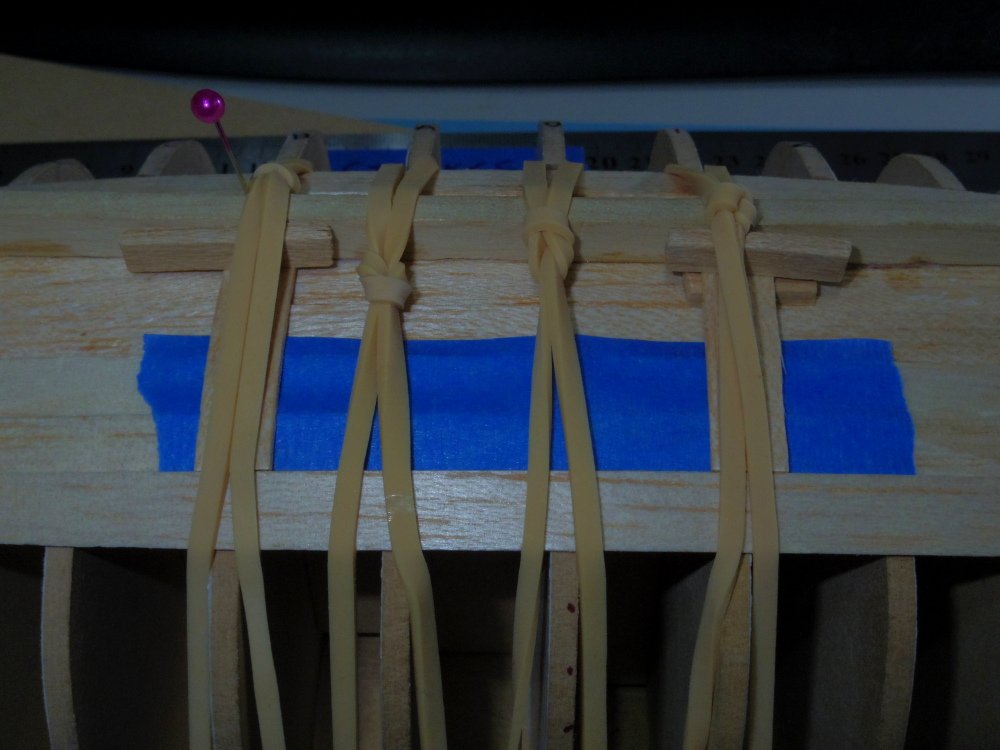
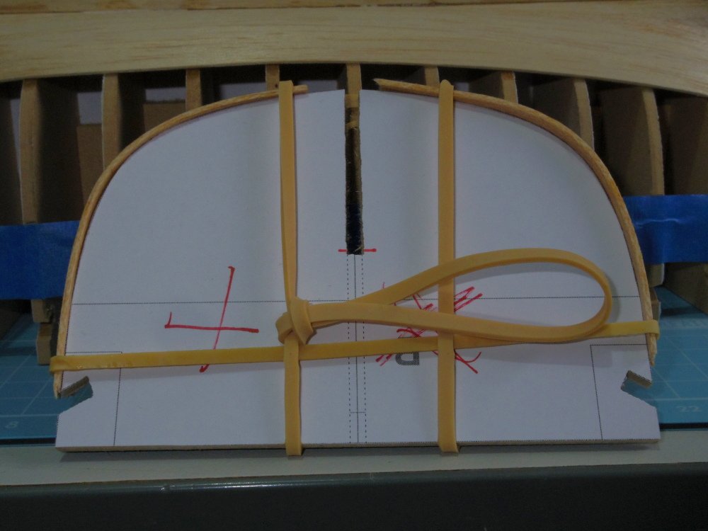
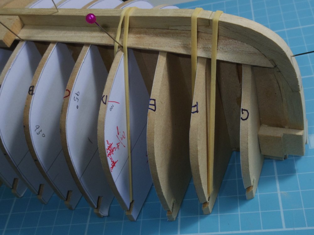
I knew I'd jinx myself, strake 6 (counting the garboard as 1) needs a little tweaking, about 3/8" (full scale) on four moulds. Not much but worth fixing. Meanwhile, I have been positioning the strakes with a 1" overlap using pins but I won't want to do this with the real model. So I am now using spacers from the keel (under the outer rubber bands in pic 1). These will be best pre-bent so I'm using scrap moulds to do this (pic 2), lucky I made them. I'm also using a scrap mould to pre-bend a strake (pic 3) the balsa is a bit brittle otherwise.
-
Added the first two tapered strakes, there will be nine a side if it works. I've learned I don't have enough hands and that's using balsa and CA. I'm pleased with the fairing so far, no lumps or bumps..
-
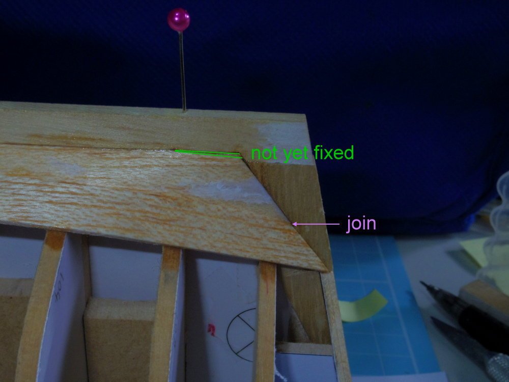
I think I'm happy with the new garboard, everything fits much nicer at the stern. And apart from the fact I cut the second plank a little short, the bow looks good too.
-
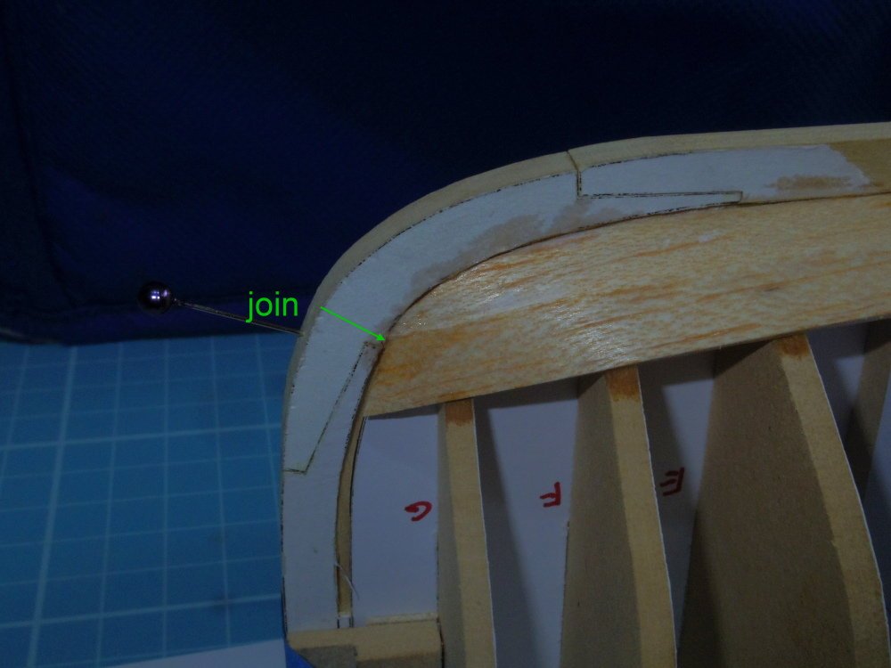
I don't think it can be done with the third plank, 0.4" in 2 inches. For now I'll make it as below and curve the rabbet up a little to fix (1) in the pic in post #9 Brain fade on 'ears' at the moment and none of my glossary's define them.
-
Problems with the third plank, too much edge set required Do you think a garboard plank shaped something is acceptable?
-
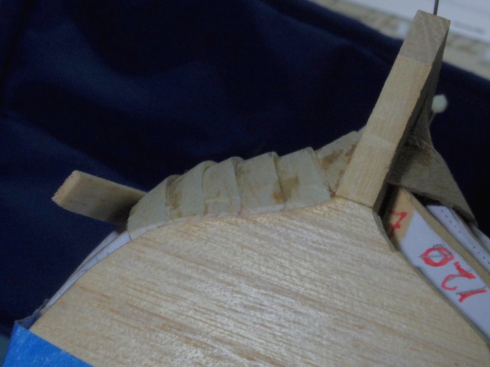
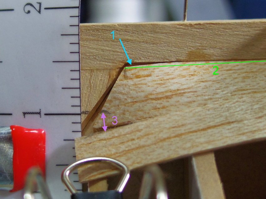
Well, planking in Balsa is paying off right from the beginning. I fitted the garboard planks and it pulls away from the keel at the stern (1) due to the bending. I suspect I will have to trim them as per (2) as I doubt I can edge set over such a short distance. The next plank needs edge setting (3) to keep the overlap and to allow for the bevel. This bevel starts out almost flat and twists round to 45 degrees at the end. Both planks are beveled. And yes, I know I cut the end of the garboard plank at the wrong angle, or is it the result of (1). I played around with the beveling needed to get the planks flush at the stern (and stem).
-
Thanks Allan, glad you popped in. ZAZ7361, the other Bounty launch, did you watch the video I posted in your 23 foot launch plans thread? 1:48 eek! Your planking will be just under 0.5mm thick, you'll almost be able to use shavings from a plane. Holly would be nice, Australia just doesn't have good modelling wood except Huon Pine, possibly the king of woods. I have some but the thought of the wastage milling small timbers is terrifying. In this model, which is largely an experiment, I'm using an Indonesian wood called Paulownia which has become available in small quantities at our largest hardware chain. It's about as dense as Basswood but more fibrous and has a stronger grain. So far it's not too bad. Meanwhile, I think I'll fully plank the current jig in Balsa in an attempt to avoid too many silly mistakes.
-
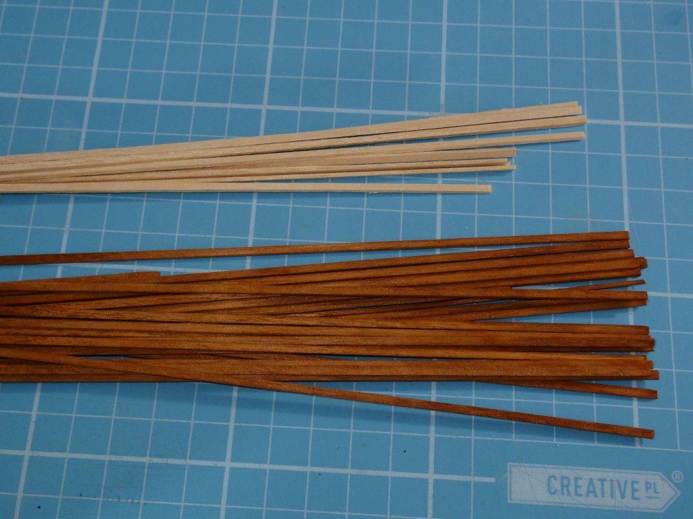
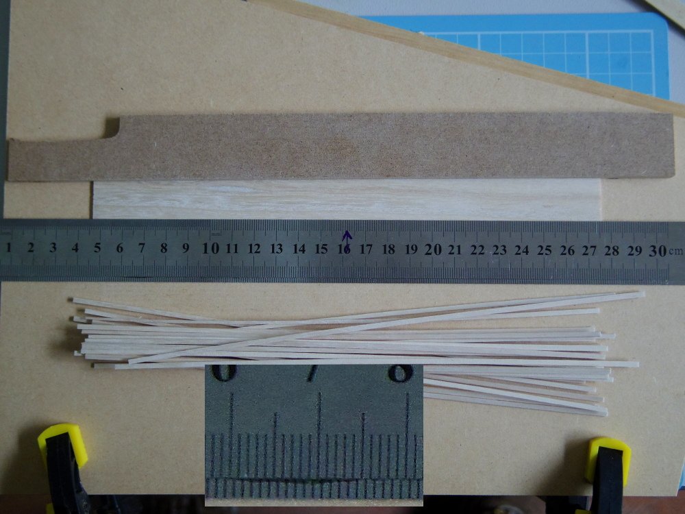
Well that went better than expected I glued two steel rulers together with a 2mm offset, added some 600 grit sandpaper to the underside, made up a cutting board with a straight backstop, sandwiched the stock between the rulers and the backstop and used several light strokes with a scalpel to cut each piece. Nice clean cuts so no need for finishing the edges. Speaking of finishing, it should be remembered that most of the inside of an open boat will be visible so pre-finishing exposed parts is advised if possible. The wood for the ribs was sanded before cutting and the ribs will be stained with a spirit based stain and coated with diluted PVA glue with a final very light sand prior to starting the build. The planking will be likewise finished on the inside. I have done a test and gluing is still fine, I haven't tested paint but I suspect acrylic paint will be fine too.
-
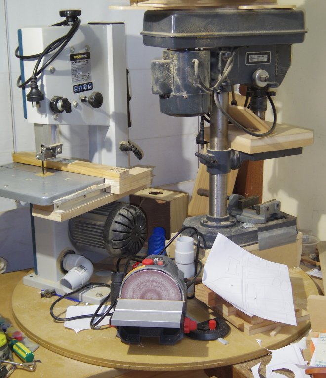
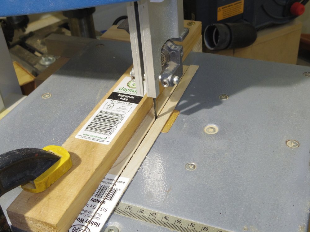
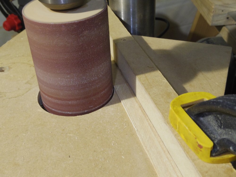
Well, I think six more moulds does it (but that included two that I sanded to the wrong line). The process for making the moulds is: 1/ Draw or edit in CAD 2/ Print 3/ Cut out roughly (except the straight edge which I cut with a ruler and scalpel) including the rubber band notches but not the slot for the false keel. 4/ Glue to a piece of MDF using a straight piece of wood (I use the fence on the band saw) to align the straight edge from step 3 with the edge of the MDF. I use a glue stick for this. 5/ Cut out roughly on the band saw 6/ Sand to shape on the disc sander beveling the edge at the same time. 7/ Back to the band saw and cut the slot for the false keel. (This is filed out later for a slightly firm fit on an offcut of MDF) I think the next step is to make a new set of moulds without the false ribs. And a new transom and probably a new keel/stem and stern post. (basically start from scratch). I also shaped and steam bent the forward end of one garboard plank, I then stuck on a post-it and trimmed it to size/shape and used it for a template for the other garboard plank. Having no mini table saw making planks is a pain. I cut them oversize on the bandsaw cleaning up the edge of the piece I am cutting from on some sandpaper on a flat board after each cut. Then sand them to size on the drill press. Then I have to make some ribs, 1mm x 2mm is going to be a pain.

-
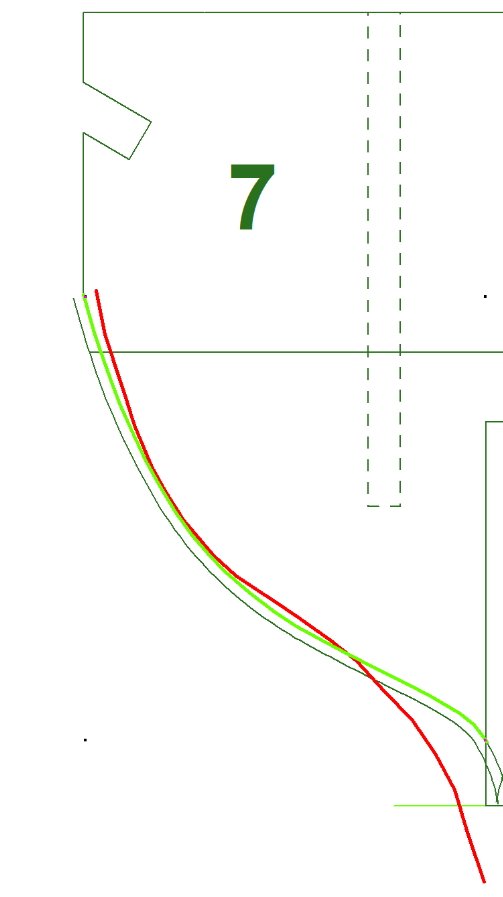
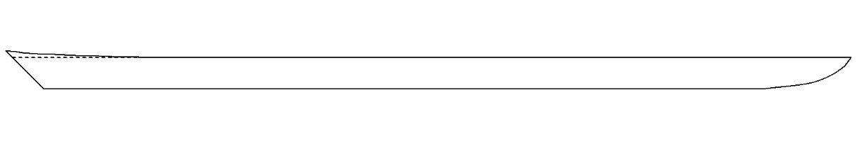
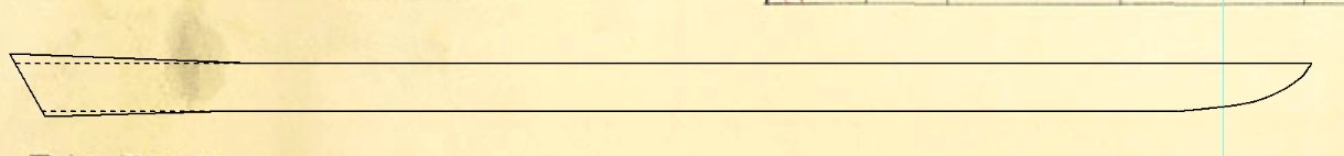
You're certainly welcome Bruce, 50ish so far with hopefully 2 or 3 to go. I could have done it in less but I wanted corrected drawings so I can make them available for others. As I said, the original drawing has some problems. See station 7 below, red is original, light green is corrected.