iMustBeCrazy
-
Posts
976 -
Joined
-
Last visited
Content Type
Profiles
Forums
Gallery
Events
Everything posted by iMustBeCrazy
-
 Unfortunately yes, I didn't have any bent trees It's simply a bit big and as it turns through almost 90 degrees the cross grain would be just as obvious as the laminations, or that's my excuse. All the floors and futtocks have been shaped, next I have to drill and 'bolt' them. Keel has been scarphed:
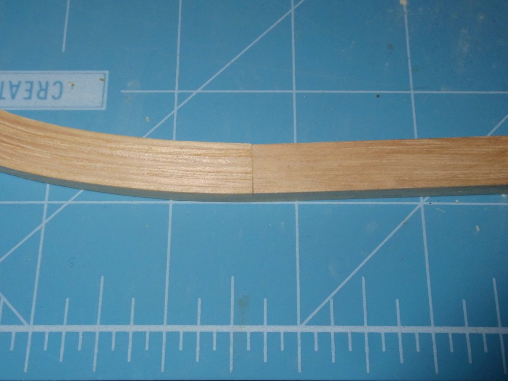
-
Initially and for larger timbers they found trees that had partly fallen over and continued to grow. Later, for smaller timbers they tortured them in diabolical machines.
-
HMS Renard 1872 by Draque - 1/24 - POF
iMustBeCrazy replied to Draque's topic in - Build logs for subjects built 1851 - 1900
Michael, you might look at using this schooner as a template, she is roughly the same size and date. She has a room and space of 24 inches versus your 22. Scaling the timbers and spaces (sided) down to suit gives: Floor ..................... 5 5/8" 1st Futtock ............5 3/8" 2nd Futtock............5 1/8" 3rd Futtock.............4 7/8" 4th Futtock.............4 1/2" Top Timber.............4 7/8" Stanchions Heel.....4 7/8" ...................Head...4" -
You should have started putting 'bends' in twigs twenty years ago.
-
They also used bent trees, modelling woods tend to come with straight grain so many of the futtocks will have short grain at some point.
-
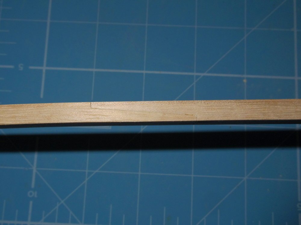
Slow going Tim, welcome. Scarph, keel to stem, done. I'm happy with it. Stem still needs to be sanded to width.
-
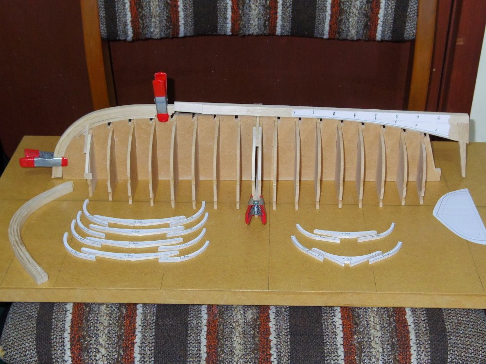
A tiny update. The jig is complete and dry fitted but I'm not going to glue it until I'm sure I don't need to change it. Frame production is underway (strange, I could swear I'd made three times as many as I have).
-
If you do, just dampen the paper with a cotton bud (Q-tip) and it will peel straight off. It will leave a glue residue which will need to be washed off (again with a cotton bud). Practice on some discards.
-
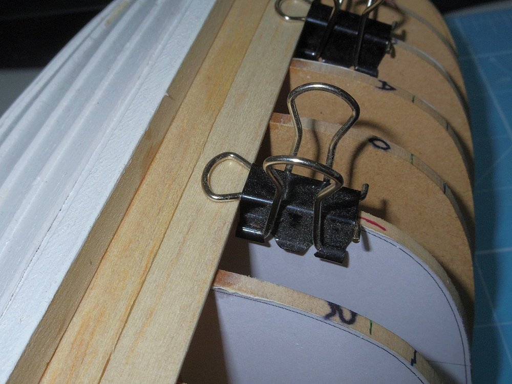
No, but I'm going to. Ok, glue needs to dry. Tim, your extensions might be a little long. You need to be able to clamp in as well as down: And when you are doing it for real, sand the planks before fitting them, particularly the inside.
-
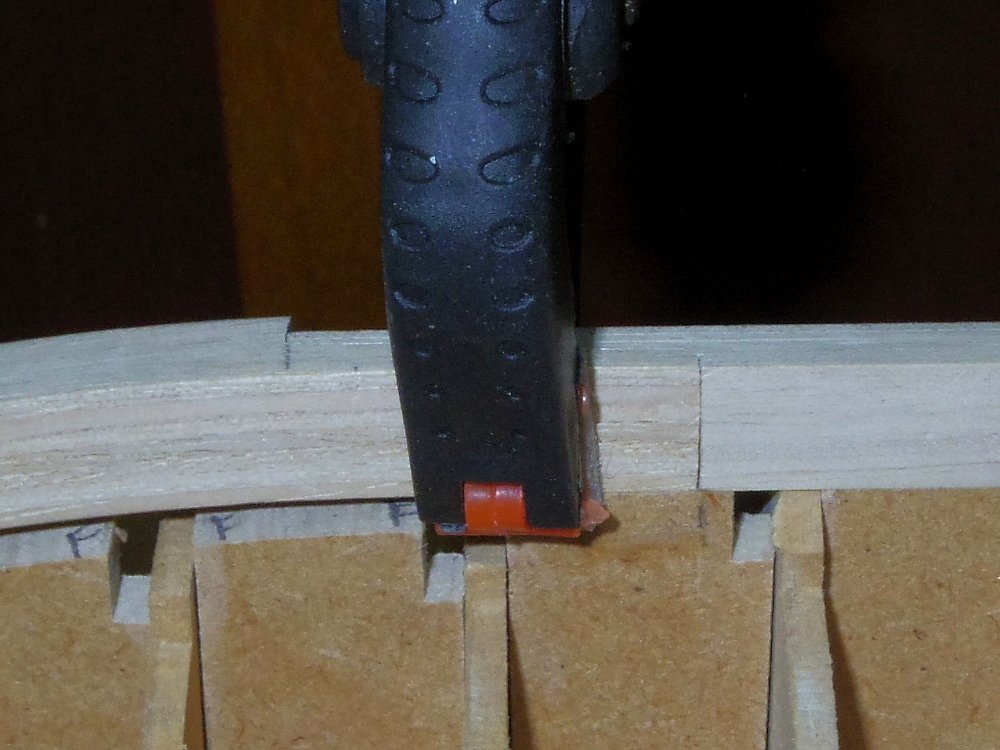
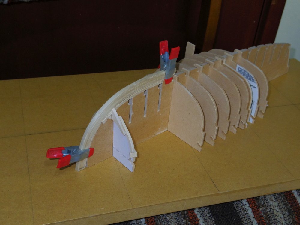
Some progress, luckily I realised I needed to leave tabs sticking up from the moulds to hold the floors in place:
-
HMS Renard 1872 by Draque - 1/24 - POF
iMustBeCrazy replied to Draque's topic in - Build logs for subjects built 1851 - 1900
Michael, when you go to print there will be a size or scale option. The default is probably something like "Fit to page" or "fit to Margins". You want the option that allows you to set a percentage like the "Custom scale" option in the screenshot. Print first at 100% and check the print for size. If it's wrong then "measurement I want" divided by "measurement I got" times 100 should give you the percentage to print at.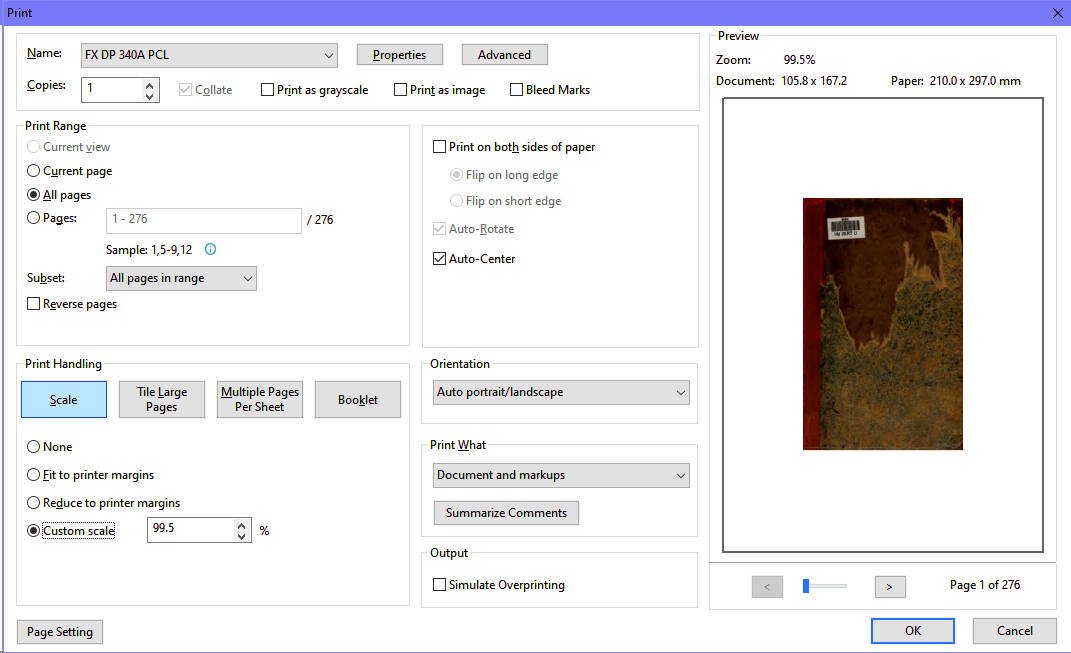
-
It's been too hot to cut wood so I separated out the floors and futtocks which I had forgotten to do.
-
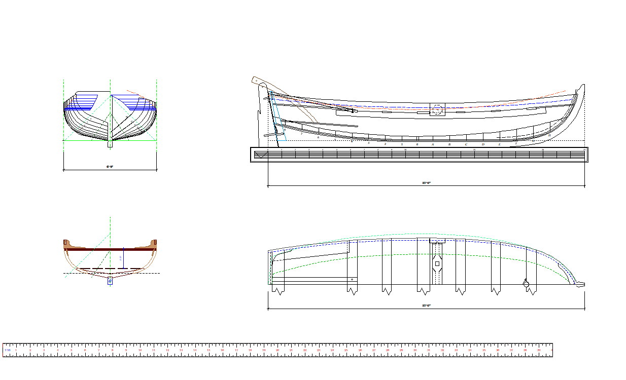
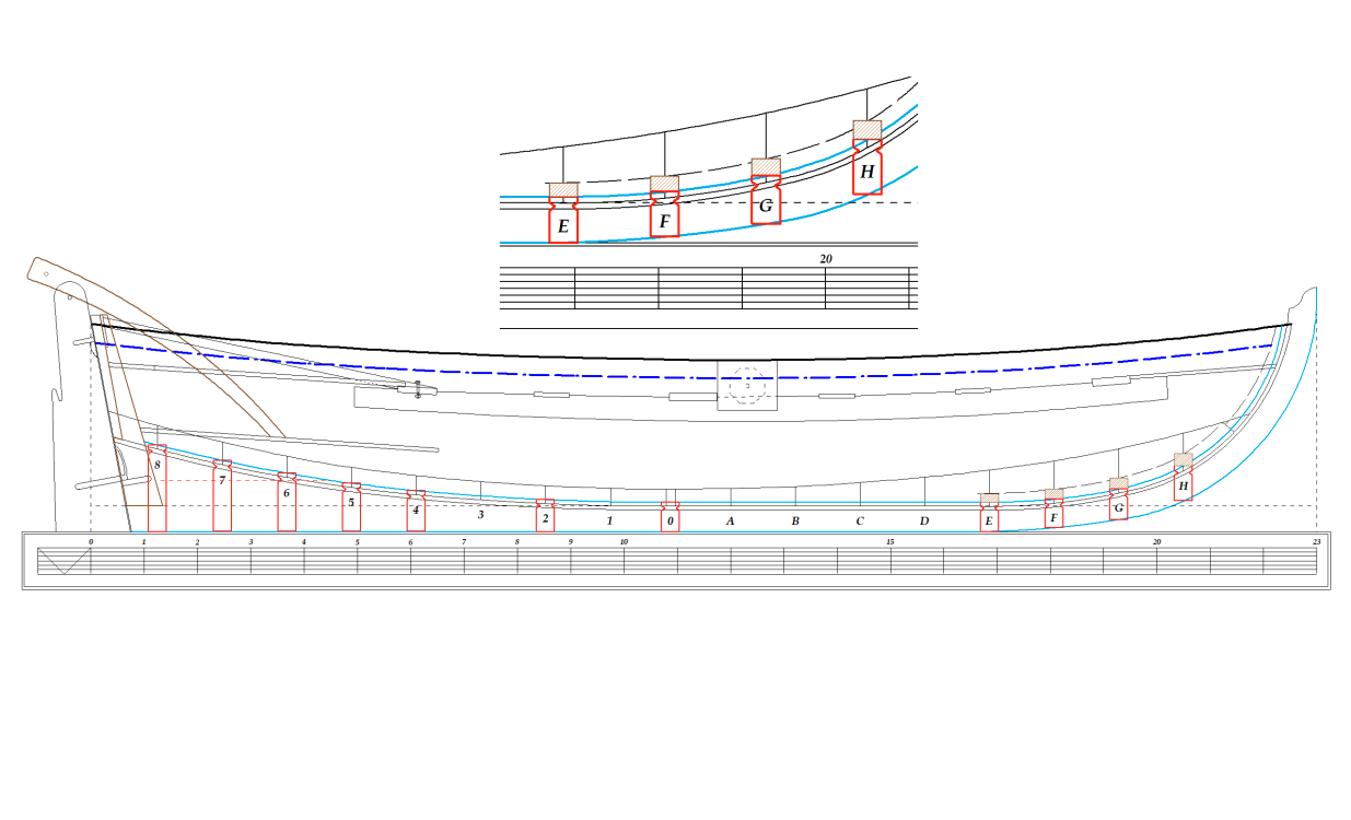
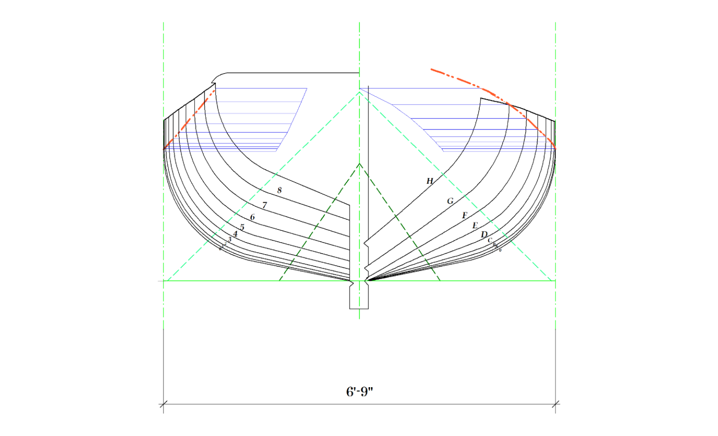
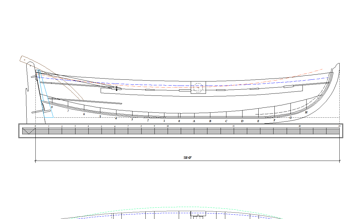
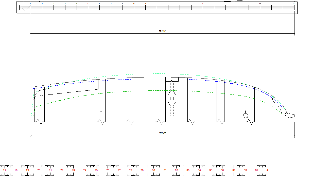
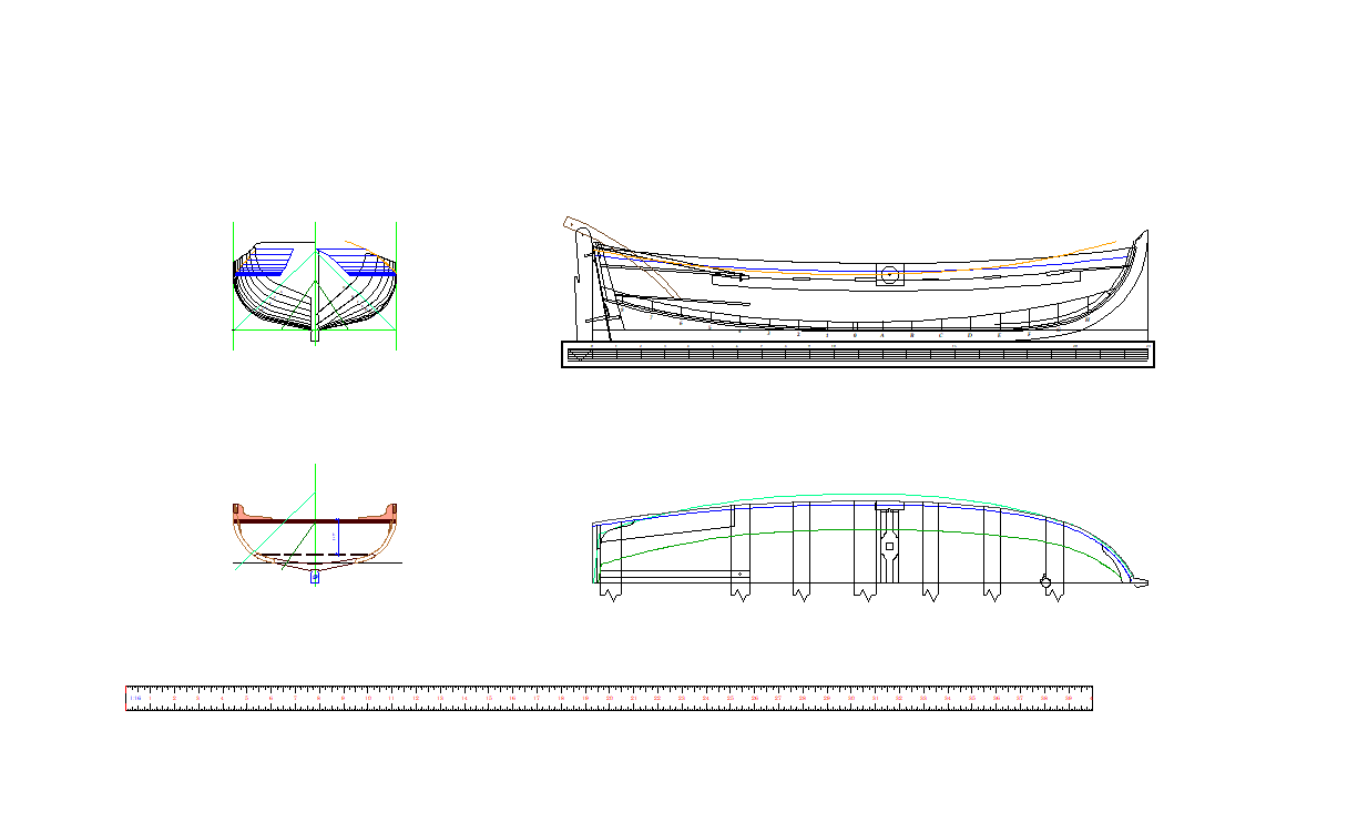
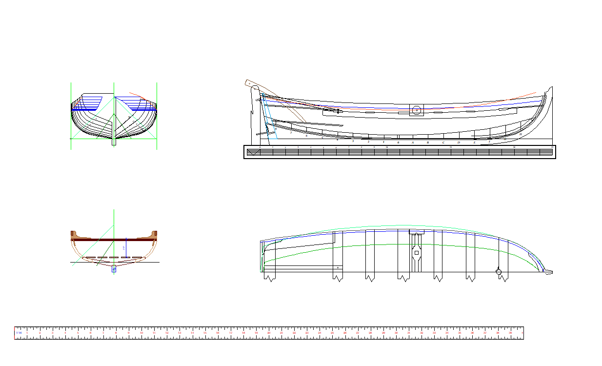
Yes yes, yet another Bounty Launch. This will be the third being built at the moment. Allan's at 1:48 https://modelshipworld.com/topic/33539-23-foot-launch-by-allanyed-bounty-late-18th-century/ Tim's at 1:24 https://modelshipworld.com/topic/33565-hms-bounty-launch-by-oakheart-scale-124-%E2%80%93-18th-century-based-on-drawings-from-national-maritime-museum/ And this one at 1:16. As far as I can see these are the first scratch built Bounty Launches on this forum excluding those built for Bounty models. Allan has been asking lots of questions in preparation for his build which has driven much research and given us some facts to work from. https://modelshipworld.com/topic/33217-bountys-ships-boat-details/?do=findComment&comment=945945 We have settled on building based on ZAZ7361 with some minor tweaks: https://modelshipworld.com/topic/33217-bountys-ships-boat-details/?do=findComment&comment=947122 https://modelshipworld.com/topic/33217-bountys-ships-boat-details/?do=findComment&comment=948363 We have each done our own drawings and I have now reached the stage where I can start building in earnest. I have made a few pieces but wanted the jig designed before starting this log. We shall see how it goes.
-
You tempt me to do a 1:24 in Huon Pine. Depends on how the 1:16 goes.
-
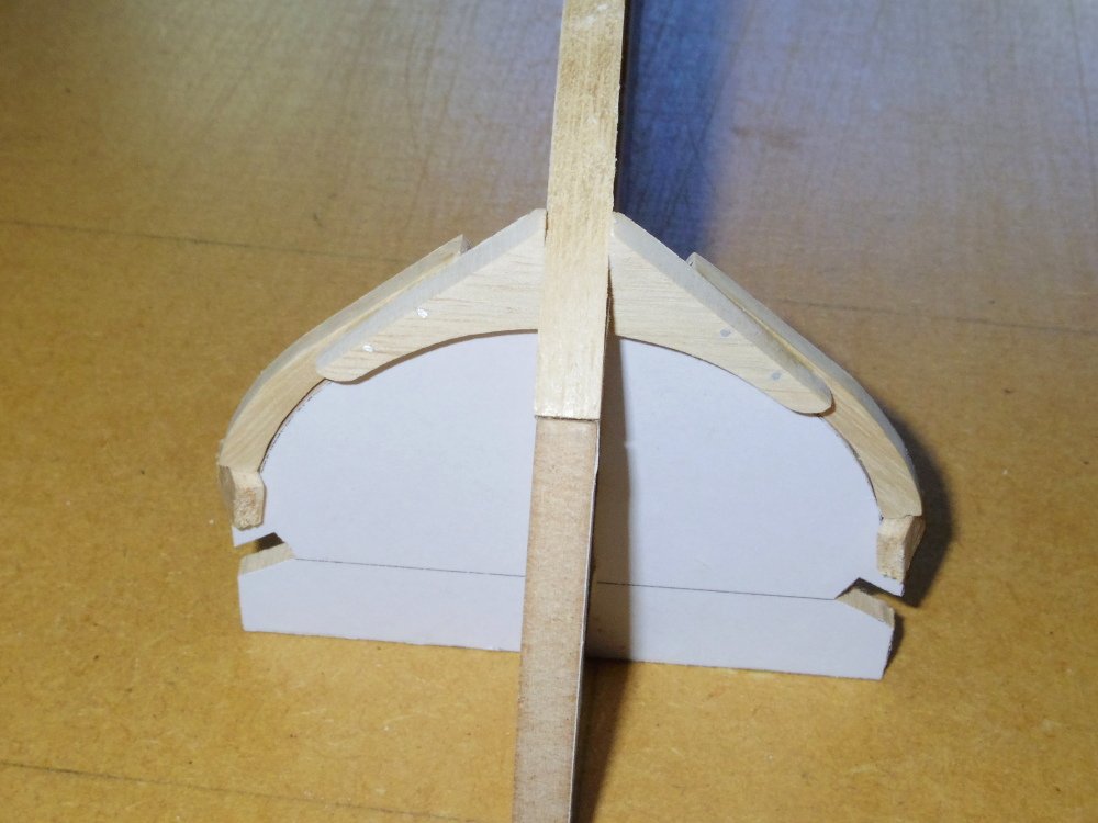
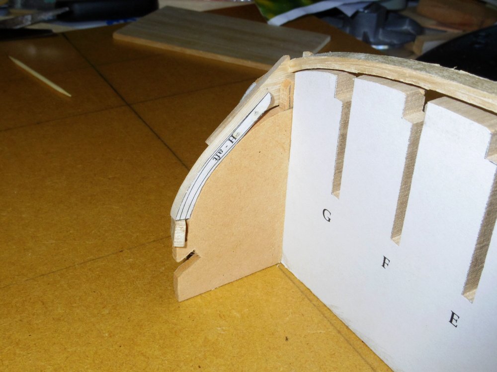
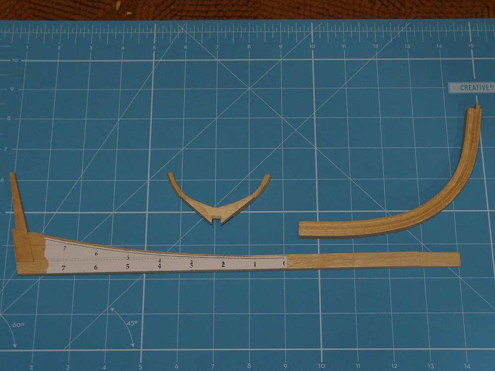
Good to hear. I took a break from the drawing. I now have frame H, a keel with deadwood and sternpost and a piece of laminated timber for the stem. But before I can scarph the stem to the keel I have to finish the frame drawings so I can design the building jig. So back to drawing soon.
-
It will later, it's not finished.
-
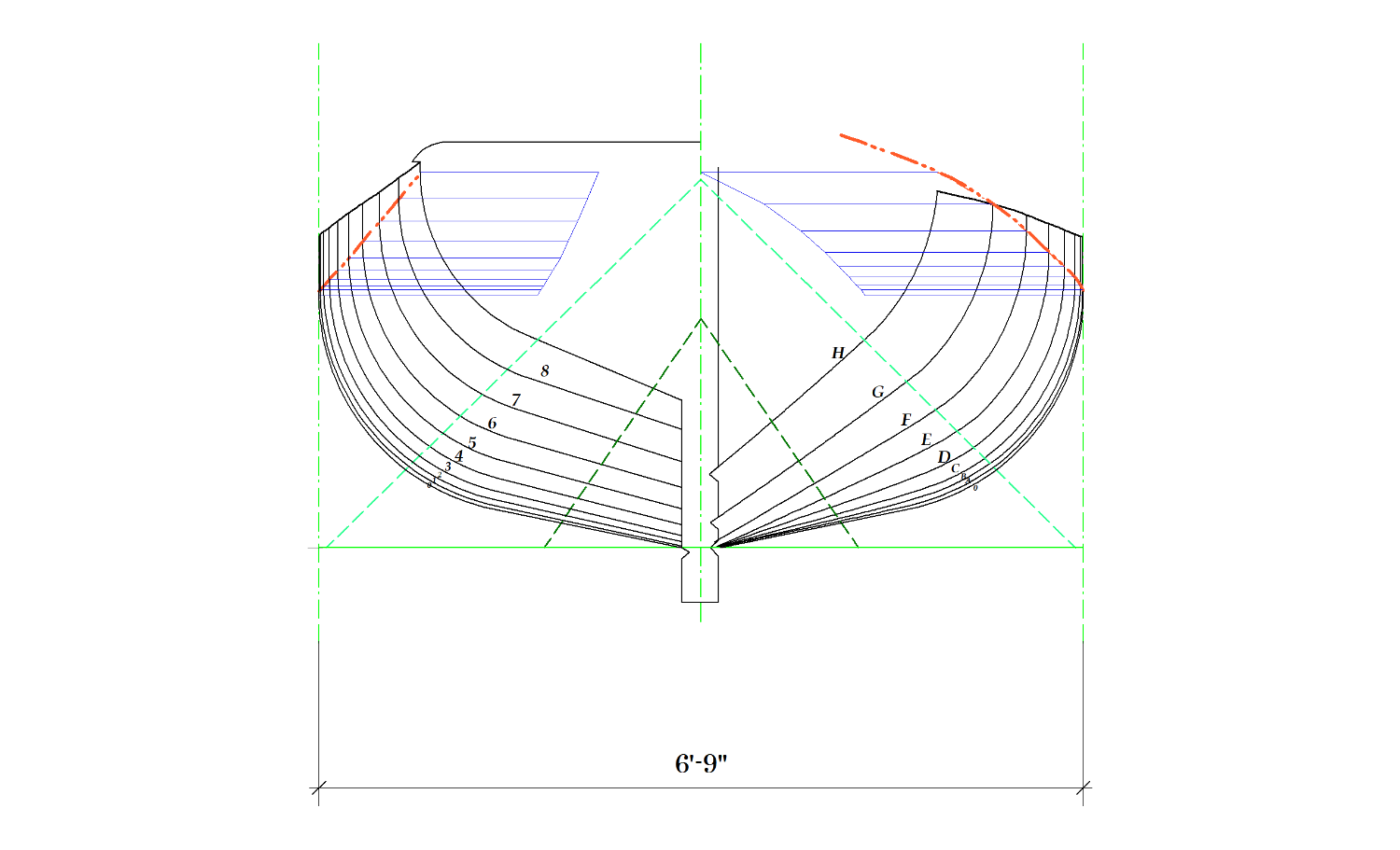
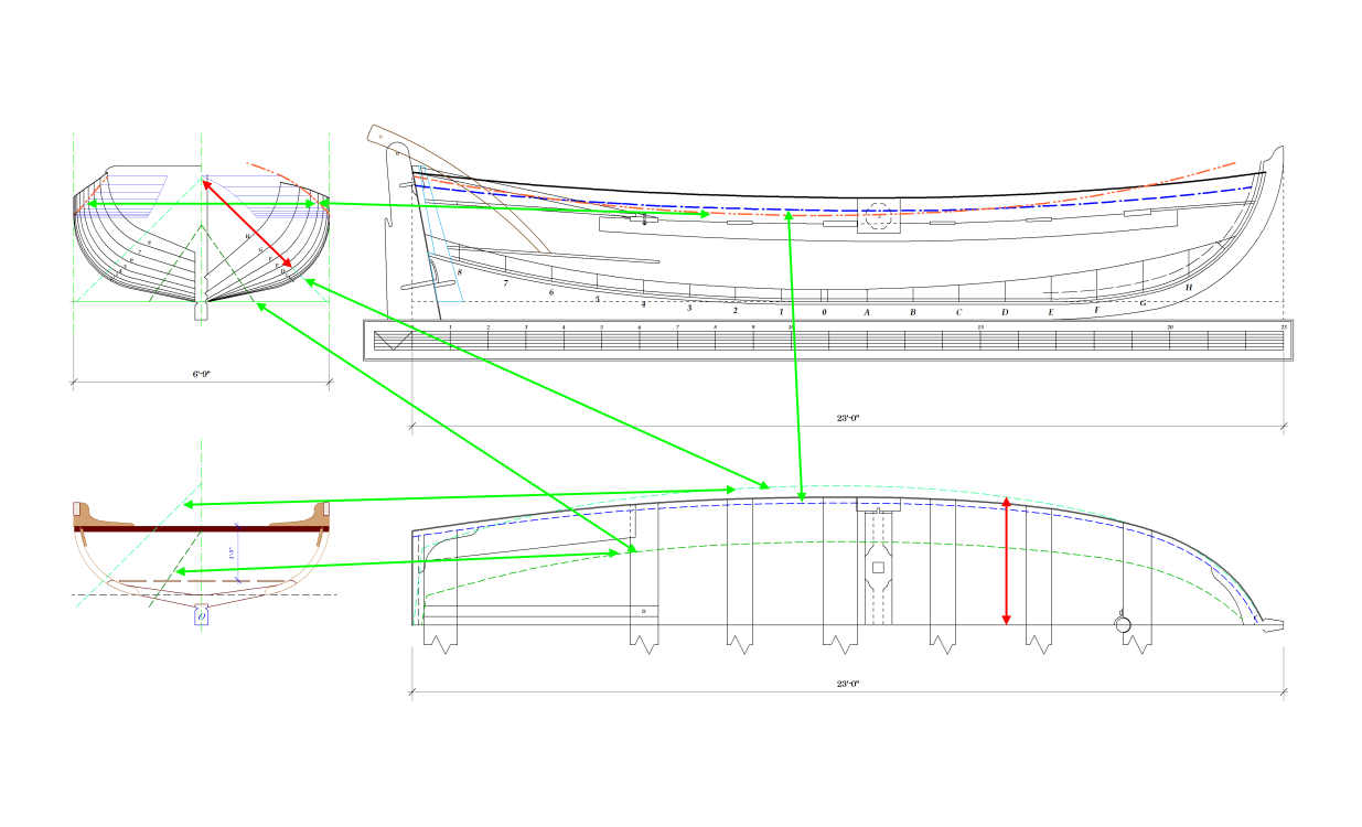
Ok, I thought it would be that one. It's one of the diagonals. Measurements in the table of offsets (which we don't have) give the length along the diagonal from the centreline to the station line this is sometimes longer than the (half) width of the hull. On my drawings I (try to) make the same reference line the same colour wherever it appears.
-
Did you identify this line? I'm not sure which one you mean.
-
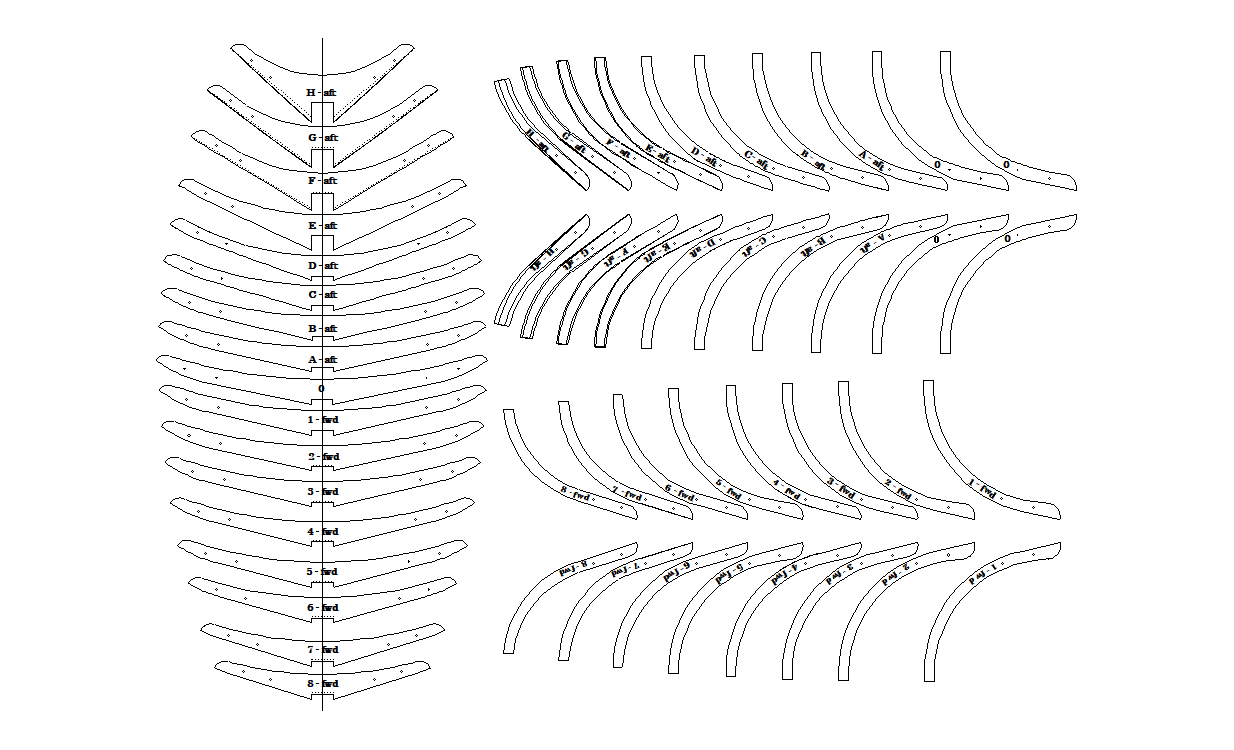
These may be of more use (bigger image in the zip file): ZAZ7361-15.zip
-
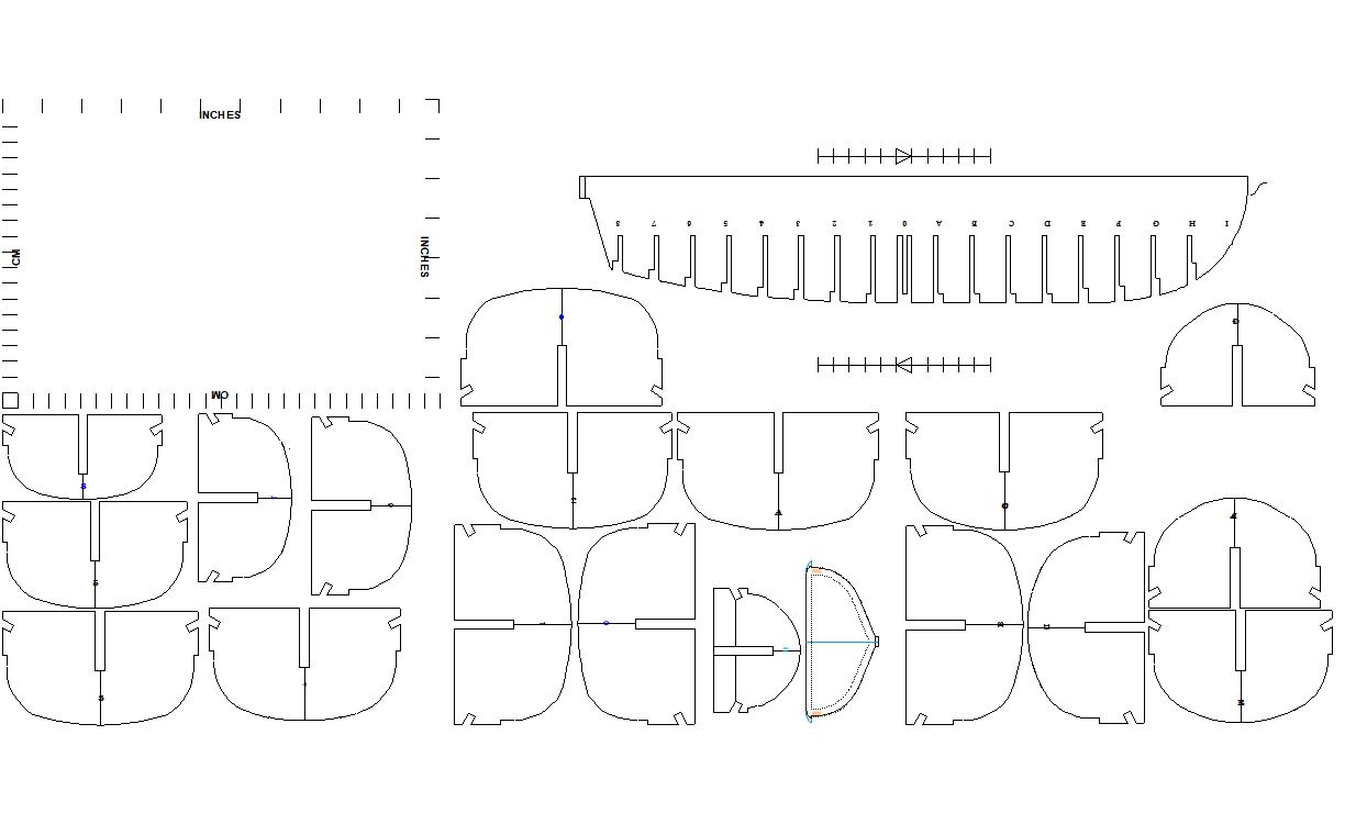
This is the dxf (re-imported into vectorworks). It's changed some line colours and but I think that's all (size difference is due to printing 'current view'). Re-imported: Original:
-
An old version of Vectorworks. Sounds like I better stick to images or PDFs.
-
Let me know if this helps. ZAZ7361.dxf
-
Speaking for myself (although I think Allan is mostly in agreement) ZAZ7361 with the lower transom from the book drawing, no washboards and the slightly heaver scantlings of the book drawing (it doesn't really matter at our scales) is the best representation.
-
HMS Renard 1872 by Draque - 1/24 - POF
iMustBeCrazy replied to Draque's topic in - Build logs for subjects built 1851 - 1900
Michael, I produced a PDF with some scale rules sometime back, you may have to adjust your printer scale to get them right but they are the right price: