iMustBeCrazy
-
Posts
976 -
Joined
-
Last visited
Content Type
Profiles
Forums
Gallery
Events
Everything posted by iMustBeCrazy
-
 So does this one, well that's going to change.
 -
Starboard side aft of the aft stanchion it bends up, there is also a kink aft of the next stanchion forward, I really doubt it's rope.
-
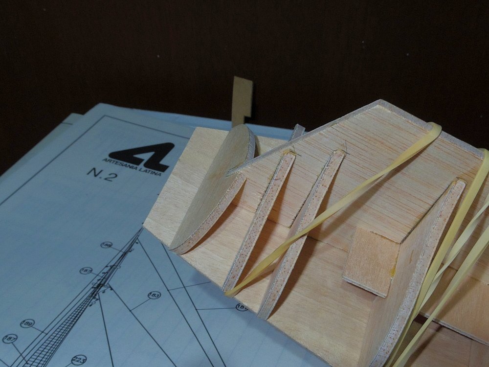
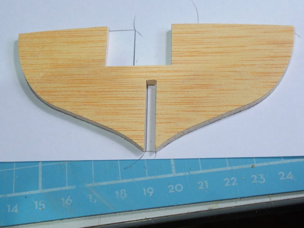
Thanks Keith. I have balsa blocks in now, roughly shaped but I need to think in 'double planked' which is new to me. The general idea with it seems to be 'make it boat shaped' instead of the shape of a specific 'boat' (understandable as a model of a replica of a generic French cutter I suppose). A 12 year old would just slap it together and be happy, maybe I'm just too pedantic. Anyway, I think I'm going to have to fit a strake then fair for the next one, then rinse and repeat until the shape finds itself. I may have to fit the keel and step about 5 steps early. We'll see.
-
From the kinks in it and the guy sitting on it my guess would be galvanised steel cable. The colour was probably dull grey with rust flecks. You could look at braided fishing line (probably with CA or epoxy wiped into it) or multi strand stainless fishing leader.
-
Relax, no you just have to make her pretty. It's a smaller gap than mine (see the last two pics in my post above). I called mine 'splinter planks'. What's that? When you stop learning, you're dead.
-
You get to claim credit for some of the inspiration. I'm not.
-
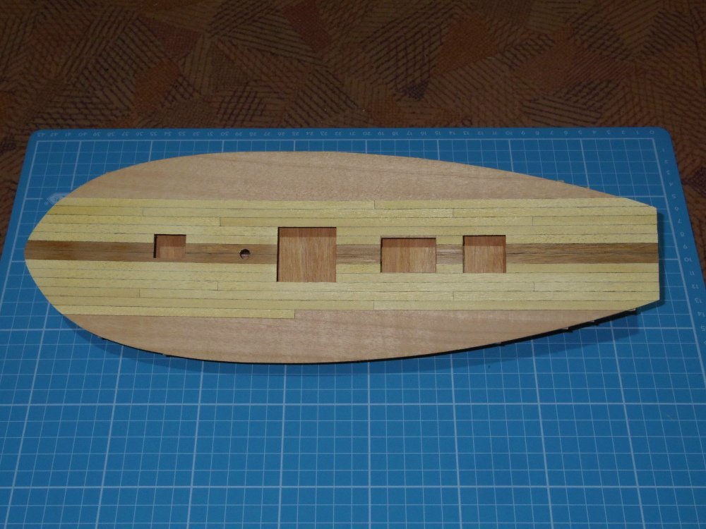
The 'sonar dome' is going away! There is a drawing that shows it in profile. I took a tracing, did some measurements, drew it in CAD, cut it out from an off cut of the original ply and glued it on. Looks almost original. I still need to add balsa fillers but I'm on the way. Deck planking is a little over half done.
-
If you download my cutter plans (see the build log) they're on page 1.
-
If it works. It's certainly not a first for this forum. For example allanyed built a 1:64 Bounty launch. Mine can carry my Renard and this cutter would make it look like an aircraft carrier.
-
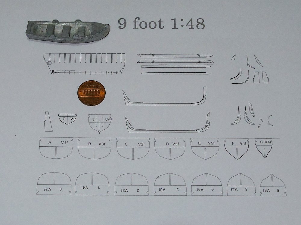
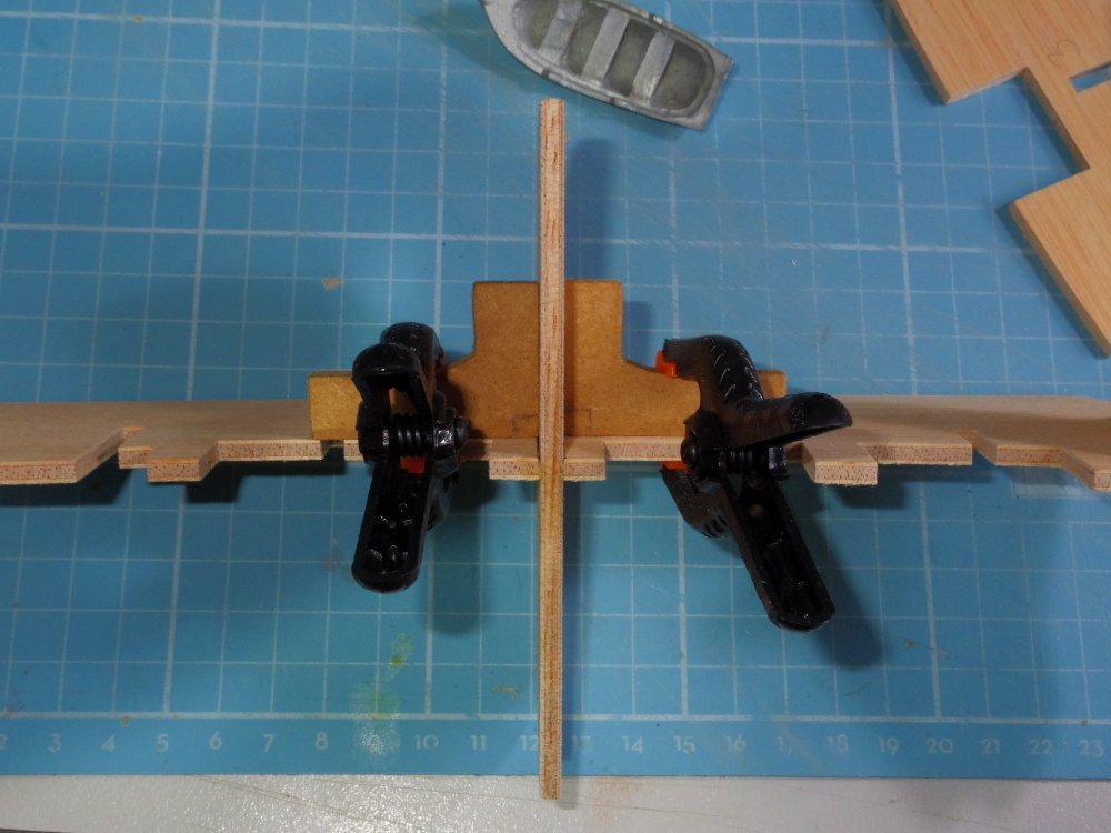
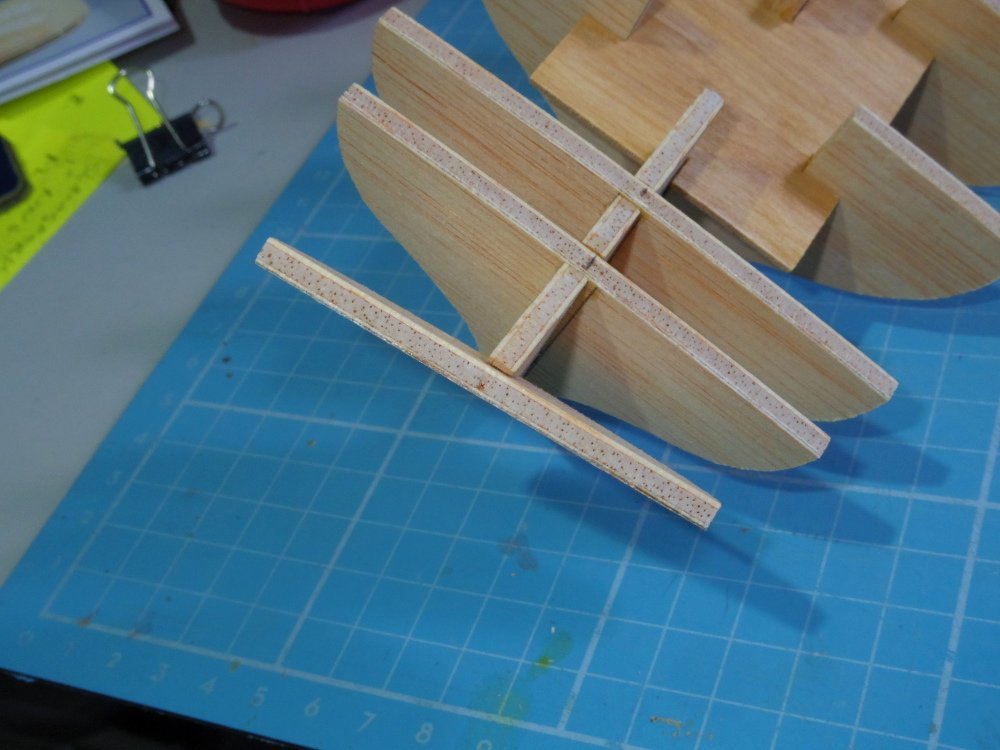
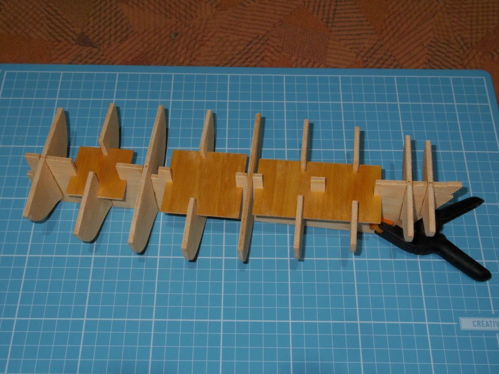
Yes, she does. Hopefully this is the start of a 1:48 9 foot cutter. (or 8'8" in 1:50) So far everything is in 1mm plywood. I'll probably fill it with balsa, fair it, cut grooves for 3 'frames', then plank it.
-
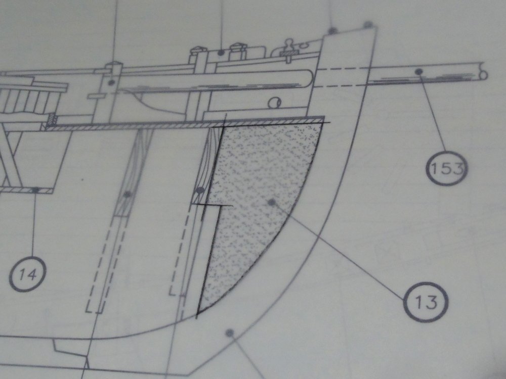
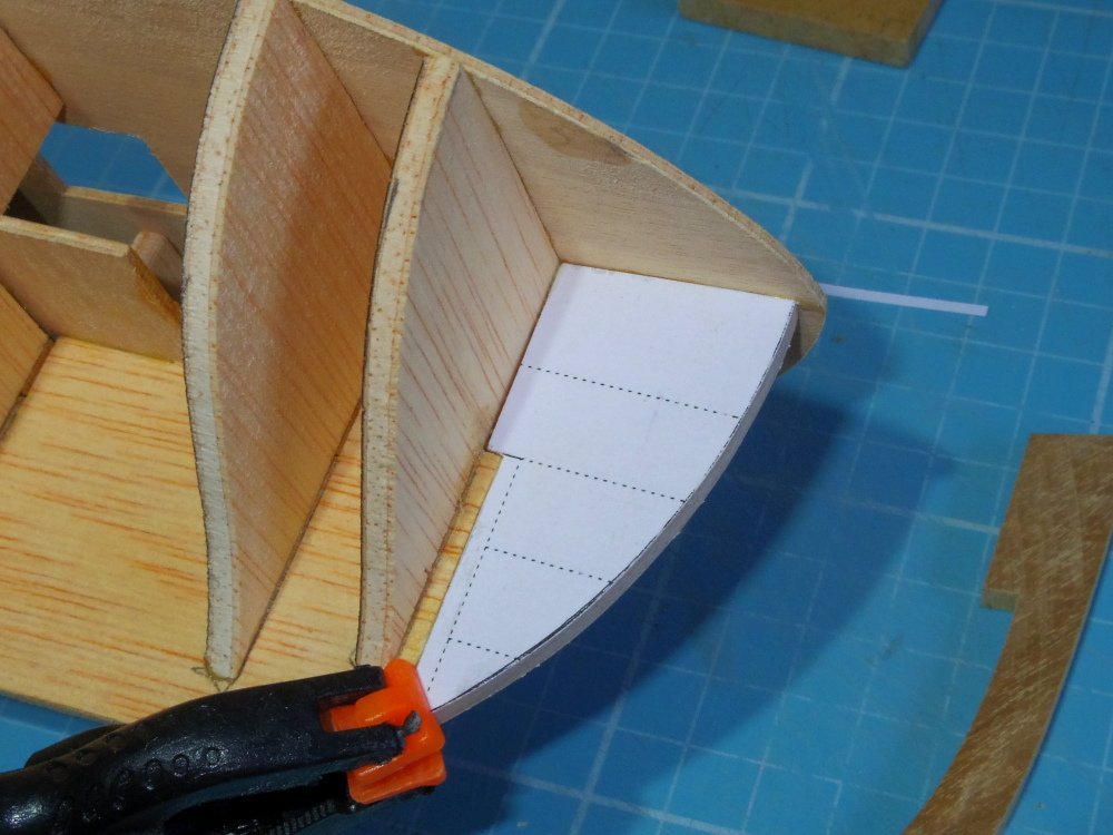
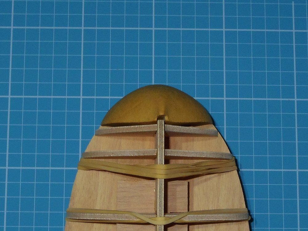
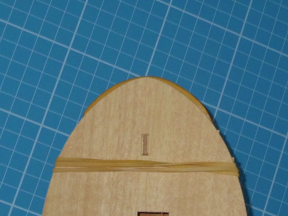
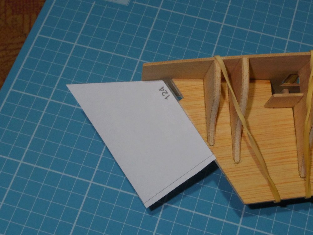
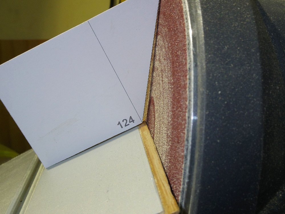
Ok, 'that little problem' has been fixed. As I said, I had the false deck fitted with 'many rubber bands'. The top of the aft mould (the problem one) needs to be bevelled for the false deck (one of the many things not mentioned in the 'instructions'). Since I drew and made a number of angle 'gauges' for setting my bench sander I used them for checking the angle needed. Not quite 124°, probably 122° but I don't have one of those so it's either make another or fudge it. So I fudged it and tested it on a piece of scrap. It worked fine. Problem fixed. Next problem, this kit comes with a bow filler block made of some composite material (something like dough with a lot of sawdust the consistency of a rubber eraser). Again no instructions, and no build logs that I can find that show this step. Apparently the first layer of planking finishes at this filler block then the joint is filled and sanded into submission. I'm not crazy about that idea so I'll have to think about it. Meanwhile I think I'm stuck with a side project, making a teeny tiny boat to replace the metal one.
-
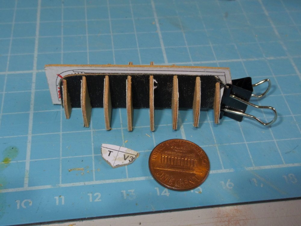
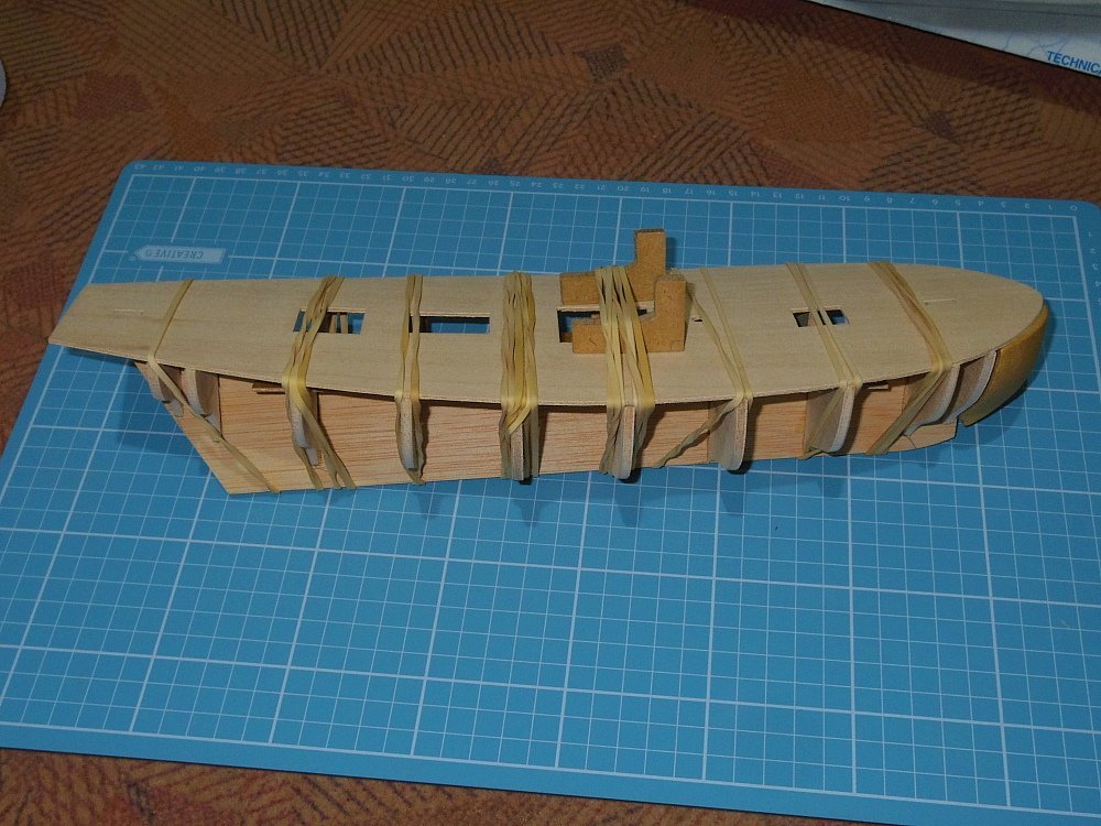
Well, I probably shouldn't have but.... As I said in the title, this is an earlier version not the current laser cut one. It looks to be a fairly easy build but one perhaps difficult to build well. We'll see how I go. First off I checked the moulds/bulkheads, production errors do happen and it's best to know if there's a problem. I would normally check them against the drawing but there aren't any so I placed each one on a piece of paper, traced around them then flipped them over and checked. Two were a tiny it out but fine to use so long as I knew about it. Fairing will fix them. I fitted the moulds to the false keel making sure they were square to the keel and that the tops were square to each other (there's a bit of slop in the slots). When I got to the mould on the stern I found the false keel wasn't cut square and of course there wasn't room for my squaring blocks, so I decided to stop before I made a mistake. I did however dry fit the false deck (and found out I can glue the mould on the stern to it, yay win) and wrap it in many rubber bands so it will take the deck curvature overnight. Oh, that small cast metal boat in pic 2 feels like it weighs more than my 16' Cutter (see sig.).
-
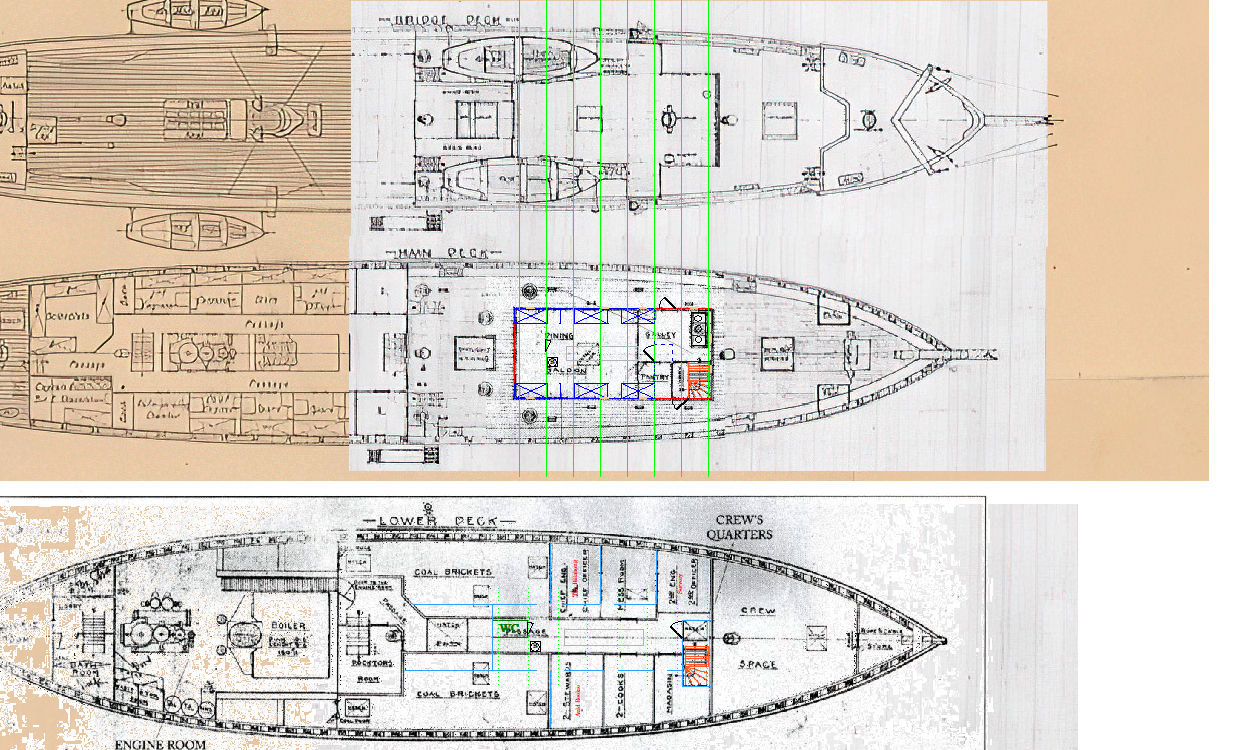
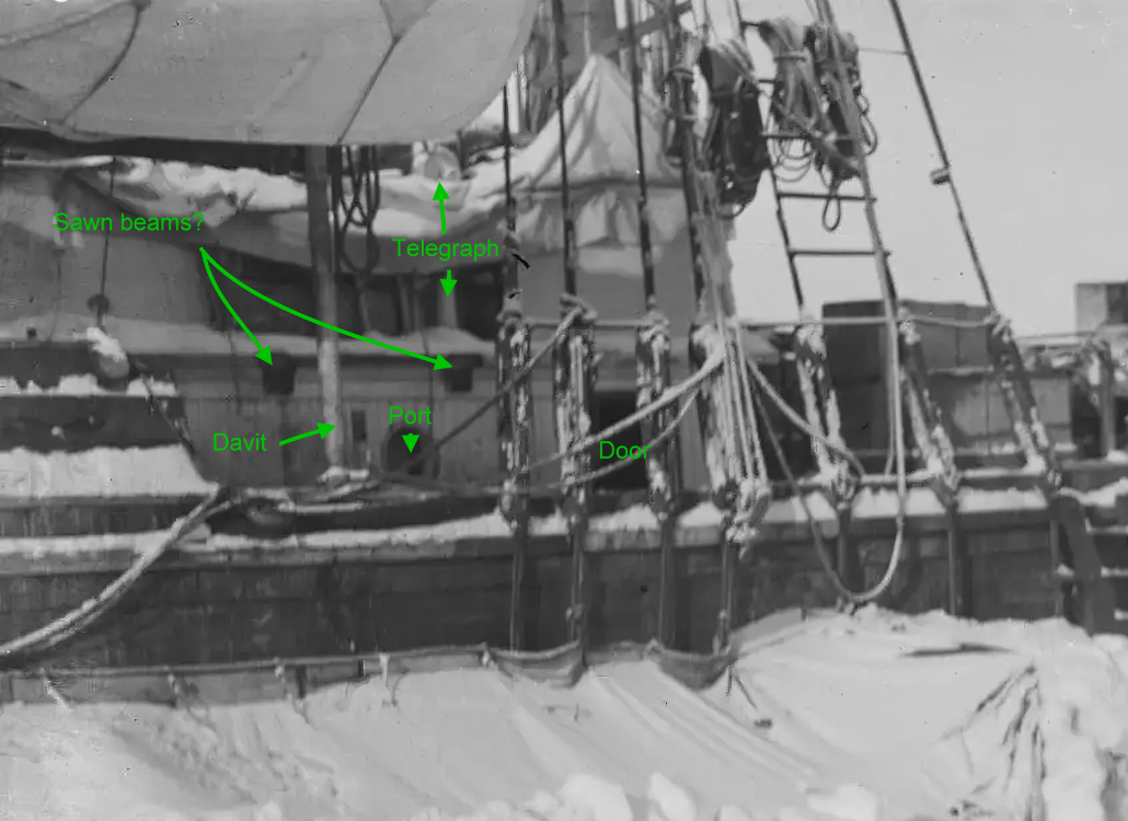
Sounds good. On 8/14/2023 at 6:00 AM, theoracle09 said: Additionally, I'm not convinced the hatch pictured in both images is over the ritz. It looks more to me the bridge was enclosed to the bulwarks, so the quarterdeck was completely enclosed. The hatch pictured would then lead to the skylight on the quarterdeck between the aft bulkhead and the aft wall of the ritz. Here's my interpretation of the above two pics: I've now come to pretty much the same conclusion although I think it was further forward (between the deckhouse and the beam). When they decked over the gap they would have fitted a hatch to access the hold with the crane, later they built a companionway on the hatch (or so I think). And it's way past time that I said - Nice work!
-
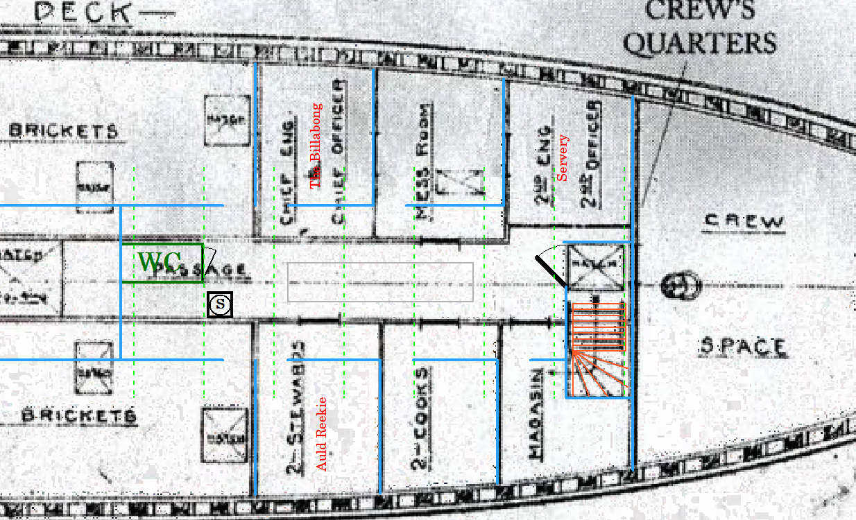
The problem is the 'ritz' seems to be below the 'ritz'. Perhaps we need to think of the wardroom / officers mess / dining saloon as the penthouse
-
More worms 'tween decks would imply to me 'on the lower deck' (between the main and lower decks), and then 'the wardroom' would be the officers mess on the main deck (under the bridge), heretofore the 'ritz'. So perhaps something like this (I know it's not going to be correct): With the wardroom / officers mess / dining saloon on the main deck untouched. Oops Wild, Marston, Crean, and Worsley established themselves in cubicles in the wardroom
-
Printable scale rulers
iMustBeCrazy replied to FlyingFish's topic in Modeling tools and Workshop Equipment
And some printers are inconsistent, if you want accuracy use calipers and calculated conversions. These rulers are useful for a quick check down to about 0.5mm (actual size) (about 5/8" at 1:32). Still, that's better than most people can cut by hand. -
Printable scale rulers
iMustBeCrazy replied to FlyingFish's topic in Modeling tools and Workshop Equipment
No worries Andy, you're welcome. -
Printable scale rulers
iMustBeCrazy replied to FlyingFish's topic in Modeling tools and Workshop Equipment
I've added 1:32 to my scale rulers HERE. Bob's right, you may have to adjust your print scale using 'Custom' or the like. -
See post #47, the rails were quite crudely cut on the starboard side but reasonably neat on the port side.
-
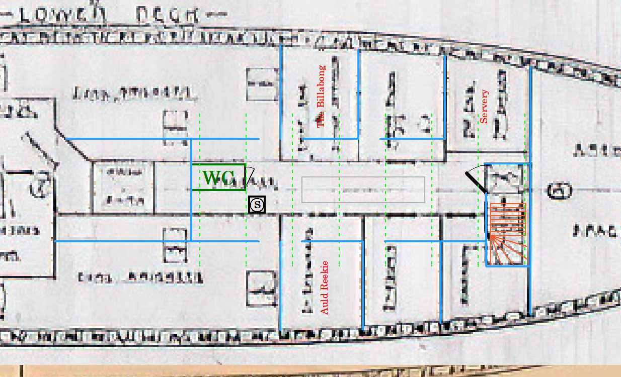
Well, that's thrown the cat amongst the worms! By any chance, was the main hold used as the dining room during winter? That might explain it. No, I don't think that works either. Then again, maybe. I assumed the pillars were to strengthen the bridge deck but I had/have a niggling suspicion the the beams aren't really 'ritz' quality. So perhaps they did duplicate the 'ritz' layout in the hold. I'm so confused. This shot shows a glimpse through to what I have been thinking is the galley but now I realise we should see a dirty great big stove if that was the case. Perhaps it's a servery below the galley? It doesn't appear to be the Officers cabins as the 'servery' would be either the Captains cabin or one of the other cabins and the door would be wrong. The door and the wall it's attached to are better quality than the partitions down the sides and are probably original. Could be the main hold/lower deck, bottom of the stairs. Sorry, rambling. So many worms.
-
Just remember, 'there are less rules than there are exceptions'. It will help you remain prevent you from slipping further into insanity.
-
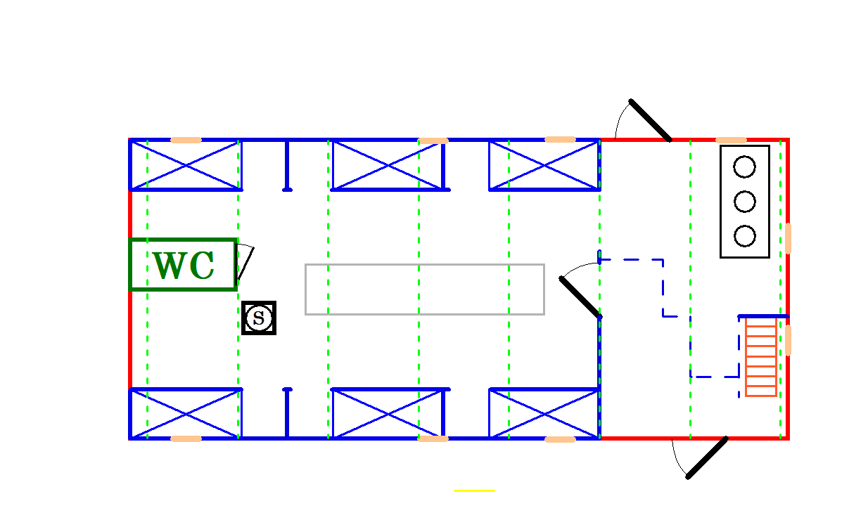
Well, I've had to make a few edits to post #35, my brain kept confusing the two doors shown inside the 'ritz'. I'm probably still wrong and I can't really guess at the 'mud room' and 'pantry' beside the galley, but I think the 'ritz' was something like this:
-
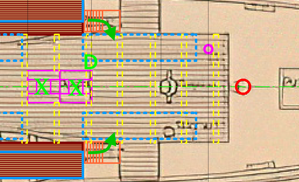
You're moving along. I was trying to get ahead and was looking at the bridge deck access. From what I can see of the wing bridges they are surrounded by solid railing and it would seem the companionways have a landing at the top with a right angle turn to access the bridge deck proper. Then I found this: It would appear that the starboard wing bridge and companionway were removed, the raw ends of the beams suggest that it was probably after getting trapped.
-
It could be ZAZ6987.
-
Even then there wouldn't be much showing unless you turned it upside down. Just noticed the British version is a slightly different shape and only about 5/8" thick: