iMustBeCrazy
-
Posts
976 -
Joined
-
Last visited
Content Type
Profiles
Forums
Gallery
Events
Everything posted by iMustBeCrazy
-

HMS Renard 1872 by Draque - 1/24 - POF
iMustBeCrazy replied to Draque's topic in - Build logs for subjects built 1851 - 1900
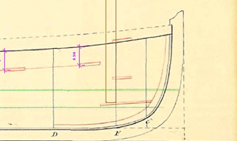
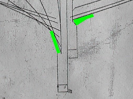
Ok, I get 3" (76.2mm) at the thickest for the garboard but I can easily see how one might get 2 1/2" (63.5mm) and 1 5/8" (41.125mm) so I would say the plans are to scale (at least horizontally) and your measurements are pretty good.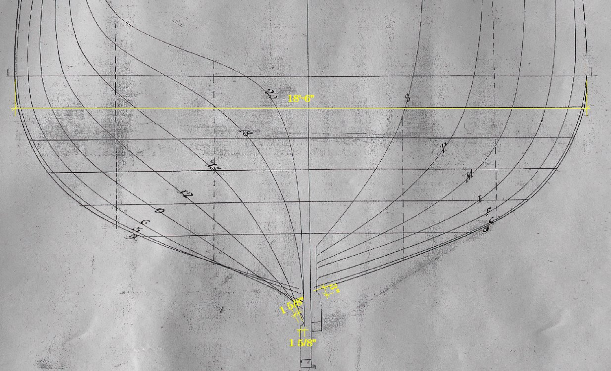
-
HMS Renard 1872 by Draque - 1/24 - POF
iMustBeCrazy replied to Draque's topic in - Build logs for subjects built 1851 - 1900
The obvious I can do, your other questions probably not. I've mostly looked a Revenue Cutters and Boats. What distance do you get between the arrows? Not really sure why, gut feeling perhaps, but I would expect planking around or slightly greater than 2" (50mm). But I'm certainly no expert. -
HMS Renard 1872 by Draque - 1/24 - POF
iMustBeCrazy replied to Draque's topic in - Build logs for subjects built 1851 - 1900
G'day Michael, I'm only guessing here but: 1/ Inside otherwise 15 would come to the outside edge of the keel. 2/ The distance between the arrows but the garboard is thicker at the keel. 3/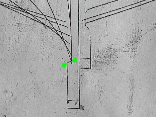
-
They are useful, make sure everything is square and stays that way. I'm currently redrawing my frames as effectively 3 drawings for each station (midships side of the futtocks, at the station line and the other side of the floors) then I can start working on the jig design. As your ribs/frames are centered on the station lines you need to make them to fit their widest dimension (midship edge) not the station line dimension so they can be faired..

-
It's fine Tim. As a first (and scratch!) build treat it as a learning experience. You are trying to learn a lot of new things all at once. Don't be too pedantic about scale and don't rush. You could brace your frames by making them taller and gluing a brace across them (to be cut off after planking). Both the forward and aft sides of the frames must touch the rabbit. You will need to make some frames deeper to allow for fairing (eg. 3 5/64" instead of 2").

-
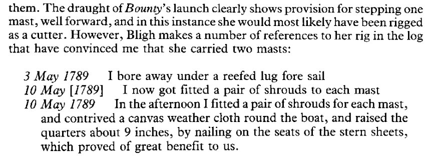
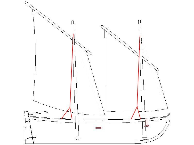
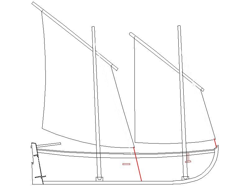
You aren't alone It's why I try to clearly differentiate between facts and guesses/beliefs (when I remember to). A guess re the drawings is that it was up to the ship/captain to rig the boats (perhaps within limits) and the mast at the bow was common to the then current choices which seem to be: Main at the bow, mizzen at the transom. Possibly the most common rig from the number of painting and sketches. Schooner/Lugger, Fore at the bow, main about midships. As you have it above and Steel suggests for Longboats and Launches (although there are several 30ft plus single masted Longboats). Three masted. Fore, main and mizzen. Single mast for smaller (under 18ft) boats. And perhaps for those drawings where no mast is shown? And of course, exceptions to every rule. No wonder we get confused. However, we are pretty certain the Bounty launch had two masts at the time of the mutiny (although three is possible, but very doubtful), a main and a fore.
-
Allan, I still have been unable to find anything that supports either of these suggestions. The closest to the single mast idea I can find comes from McKay but a cutter rig on a mast that far forward makes little sense. None of Bligh's writings or logs that I can find ever mention working on the rigging of any of the boats during the voyage (with the exception of the fitting two shrouds to each mast after the mutiny). There are mentions of "carpenters working on launch" or "carpenters working on boats", in one instance to repair damage incurred during a storm, but just as "I'm keeping the crew busy" type log notes. I'd love to know what your source is.
-
Allan, Bligh wrote "The Size of the Boat was 23 feet from Stem to Stern and Rowed Six Oars" in a letter to Banks (fact 8). I'm fairly happy that the drawing in Bligh's books (RMG ZAZ7848) is a good representation of the Bounty Launch and that ZAZ7361 is an evolution of that based on Bligh's experience. But I could be wrong. She certainly is Ollie. (Laurel and Hardy). Me too! They show a Main and Mizzen, a common rig on boats, but Bligh makes the following notes in his log: 1/ It was about 8 o’clock at Night when I bore away under a reefed Lug foresail 2/ under close reefs Fore Sl. & Main Sail So the Launch had Main and Fore masts with a lug sail on the fore and probably (but not certainly) the main.
-
Allan, after a bit of headbanging I have the following to offer. Using the Steel tables in Boats of Men-of-War: Looking at "The dimensions of rigging........." pages 98/99 we find it based on ship classes not boat lengths so we have to find a class of ship that had a 23ft launch. On to "Boat establishments 1670-1800" on page 57. Note there is no mention of launches before 1780 and as of Nov 1780 Launches are to replace Longboats. So we find that in 1781 fifth rate 36s & 32s have a 23ft or 24ft launch. Back to pages 98/99. And we find no Launches listed even though they were to replace Longboats starting 14 years earlier. So we'll use the Longboat info for 36s or 32s which both give: Shrouds- 4 off, 3" rope, iron thimble 16 fathoms. Laniard - 1" rope 8 fathoms. Stay - 1 off, 3 1/2" rope, iron thimble 5 fathoms. Laniard - 1" rope 2 fathoms. Note: the lengths in red were omitted from Boats of Men-of-War. They seem to include some spare rope. So, 4 shrouds means 2 per mast each with a thimble at the end. I assume that the shroud laniards run from the boat up through the thimble back to the boat giving a 2:1 pull. Where the stay goes, probably from the main mast but........ However, there is no mention of shrouds or stays for any boat type but Longboats and Bligh's wording is not clear. But if shrouds already existed and attached with laniards as above then there would already have been support for the canvas splash screens. It's still a puzzle.
-
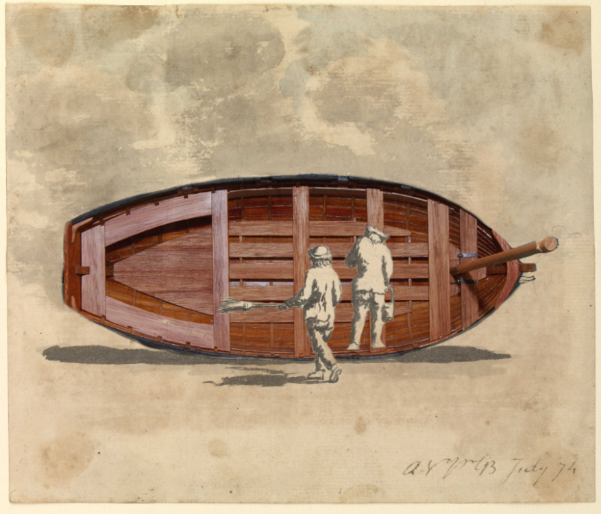
Allan, something like this seems the norm: https://www.rmg.co.uk/collections/objects/rmgc-object-67278 https://www.rmg.co.uk/collections/objects/rmgc-object-68522 https://www.rmg.co.uk/collections/objects/rmgc-object-248094 Shrouds seem optional?
-
I would hardly say that. There is also a later note: "Sailmakers mending the Awnings and Boats coverings."
-
I was just reading Bligh's log and came across this: Saturday, Jan. 12, 1788 8:00 am Employed about a Variety of necessary duties for the ship & fitted Boats Coverings. So, they used covers of some sort in 1788.
-
Well, I have the Model Shipways version in that scale which is why I built this cutter in the same scale, but I now know that there are too many errors in it so I think I will build a more accurate one. Although I can easily re-scale my drawings, at smaller scales construction techniques dictate the accuracy one I can achieve. That said, if anyone wants a different scale 16ft cutter let me know. Unfortunately that will depend on historically accurate knowledge. Well, I guess that next after the launch should be a 20ft cutter giving the full set.
-
Thanks Allan, I think that's where I'm going too, but in 1:16.
-
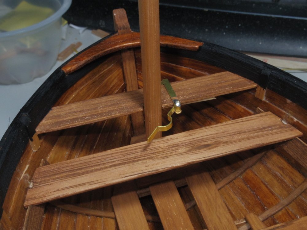
Drawings as promised, they don't show everything as I've left out the simpler bits. Page 1 is for scaling your prints plus some angle gauges for fairing the moulds. I apparently didn't draw strake 2 but it's basically a rectangle with the ends shaped to fit so it shouldn't be a problem. I haven't drawn the thwarts or mast support but those are pretty basic. The wood I used is metric, you will have to make your own adjustments for imperial thicknesses. I've provided two versions for A4 or Legal sized paper. Let me know if printer margins are a problem or if I've missed anything. This log is the 'instructions' but I'm happy to answer questions. 16ft Cutter 1in16 A4.pdf 16ft Cutter 1in16 Legal.pdf
-
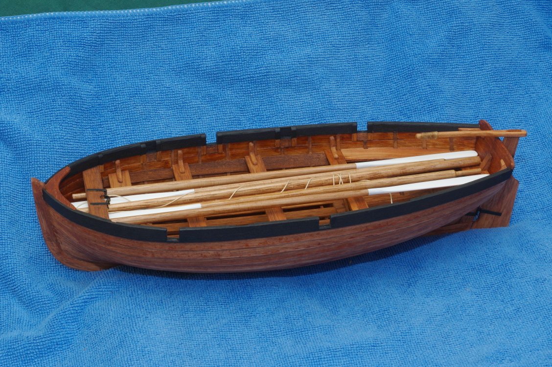
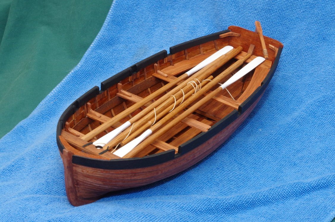
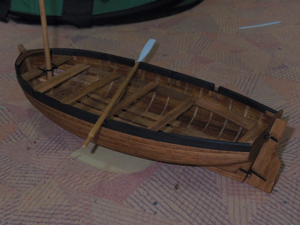
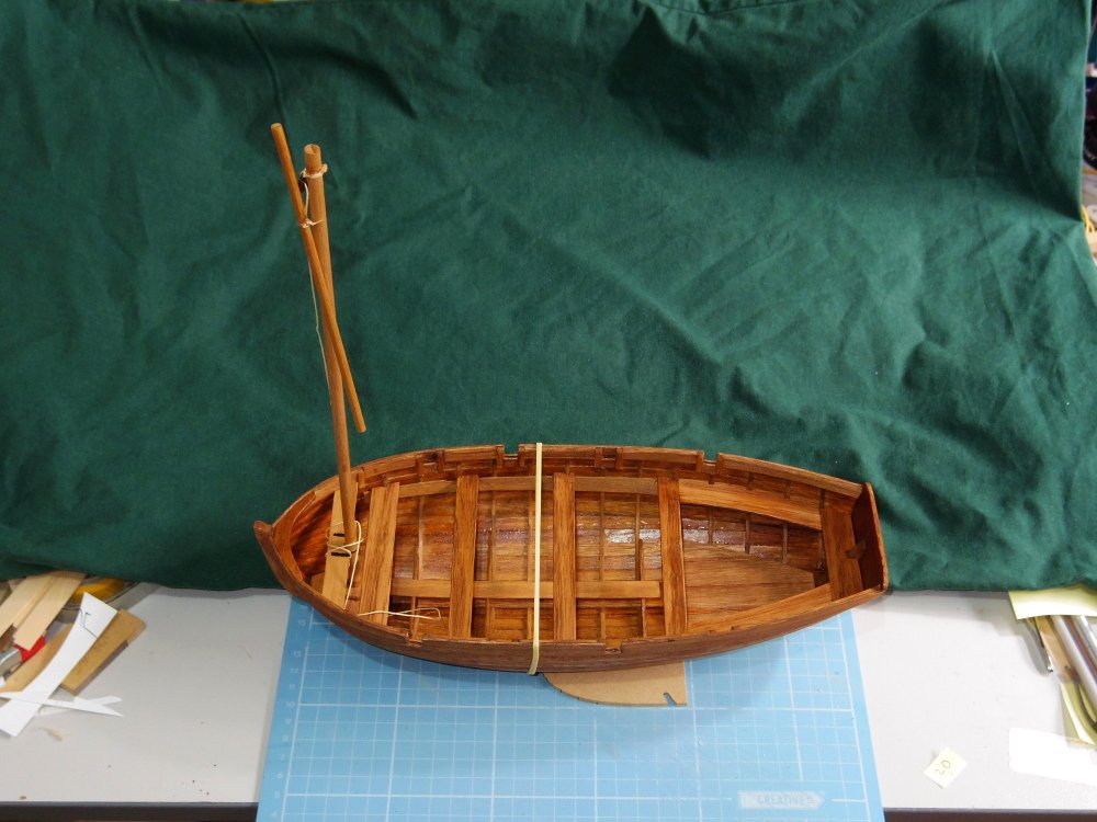
Well, the lads got a coat of paint on the interior the other day but the next two days were too hot for painting. So I fitted the thwarts and knees, tapered the mast a little and made the last two oars. Yesterday the lads finished painting the hull and this morning I painted the oar blades. I think all that's left is to tidy up the drawings and post them.
-
Well, I did get a little more done, another oar and the tiller: Oh, and a little more playing around:
-
No physical work going on as I pinched a nerve in my wrist, it's getting better though. Meanwhile, a virtual diorama:

-
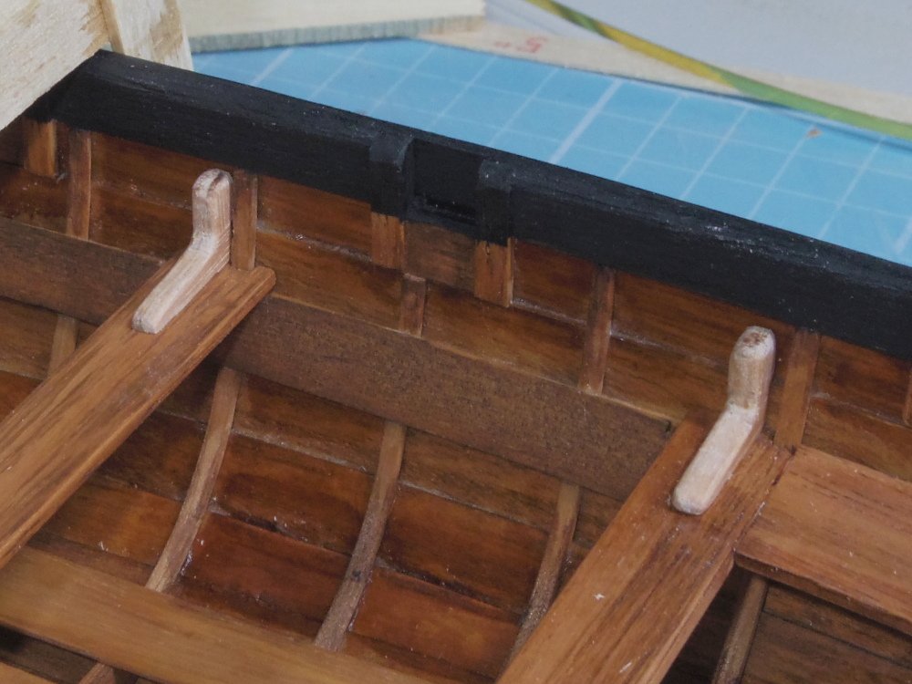
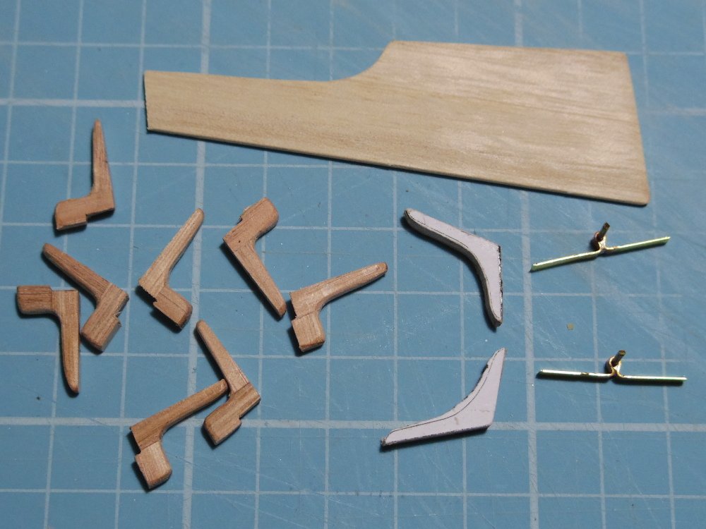
Update time: Knees are all finished but not fitted (except the transom). Ironwork is done, fitted and functional but needs the paint touched up. What has slowed me down is trying to come up with oars that I like (and can make). I think I'm happy with the look but still need to make a set that match.

-
I'm happy enough, and yes, I dislike seeing frames on cutters and ribs on launches or frames poking through as knees.
-
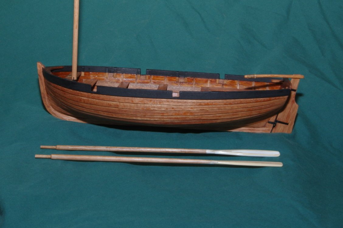
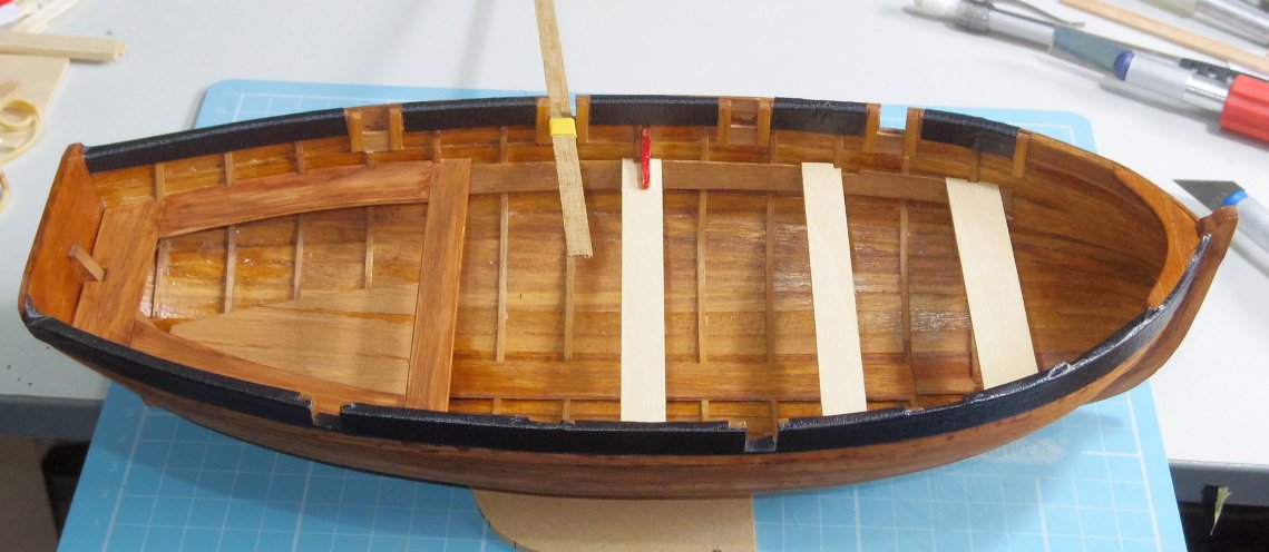
Thanks Allan. However, the ribs are spaced at 12" where 8" would probably be more realistic. Also contemporary sketches show I could have used heavier ribs. Oh well, live and learn. Some progress, there's about an hour in each knee.
-
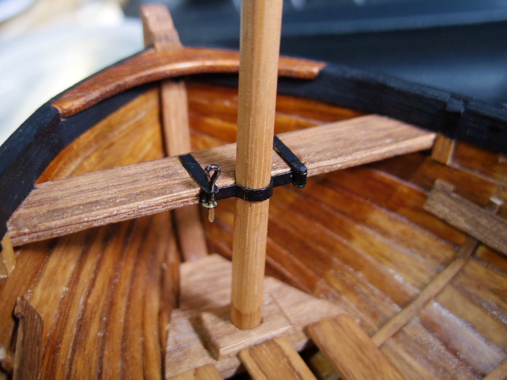
It feels like I'm getting close now. Just knees, rudder, sail?, oars, cleat, mast clamp then clear coat.


-
More progress and a little more mocking up.
-
A quick mockup with black washboards. Yes they will be matt black.
-
Allan, you've sold me, it's not as pleasing to my eye (I think it would look better at station D ) but it's probably right.