HOLIDAY DONATION DRIVE - SUPPORT MSW - DO YOUR PART TO KEEP THIS GREAT FORUM GOING! (Only 24 donations so far out of 49,000 members - C'mon guys!)
×


iMustBeCrazy
-
Posts
967 -
Joined
-
Last visited
Content Type
Profiles
Forums
Gallery
Events
Everything posted by iMustBeCrazy
-
 I've used it and it's ok but I grabbed the wider ( 1 1/2") tape one time and it stays flatter. You don't really need see through. Pressing the pencil against the edge/corner of the plank will give you a good enough line. You don't want an exact cut, leave a little 'meat' to sand off.
 -
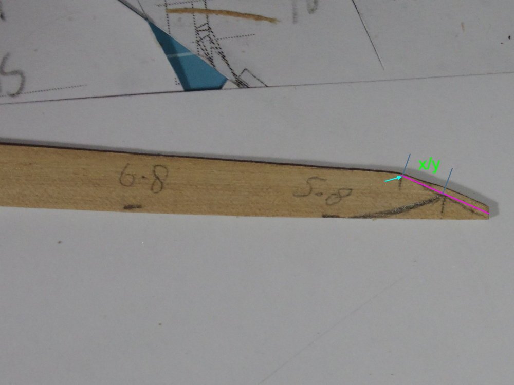
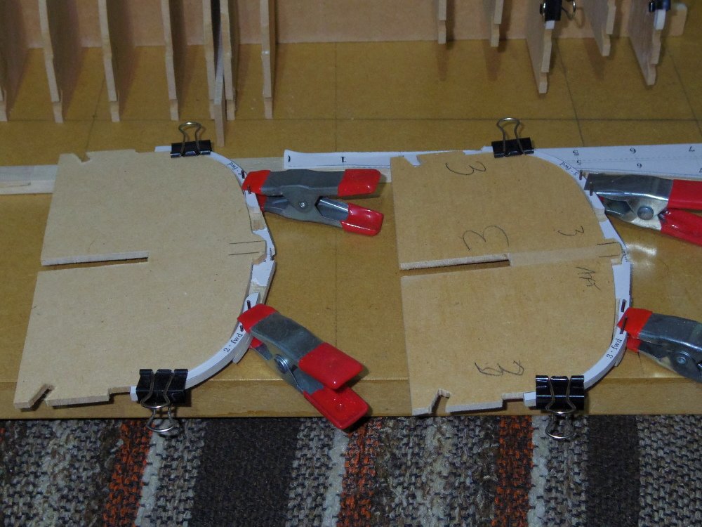
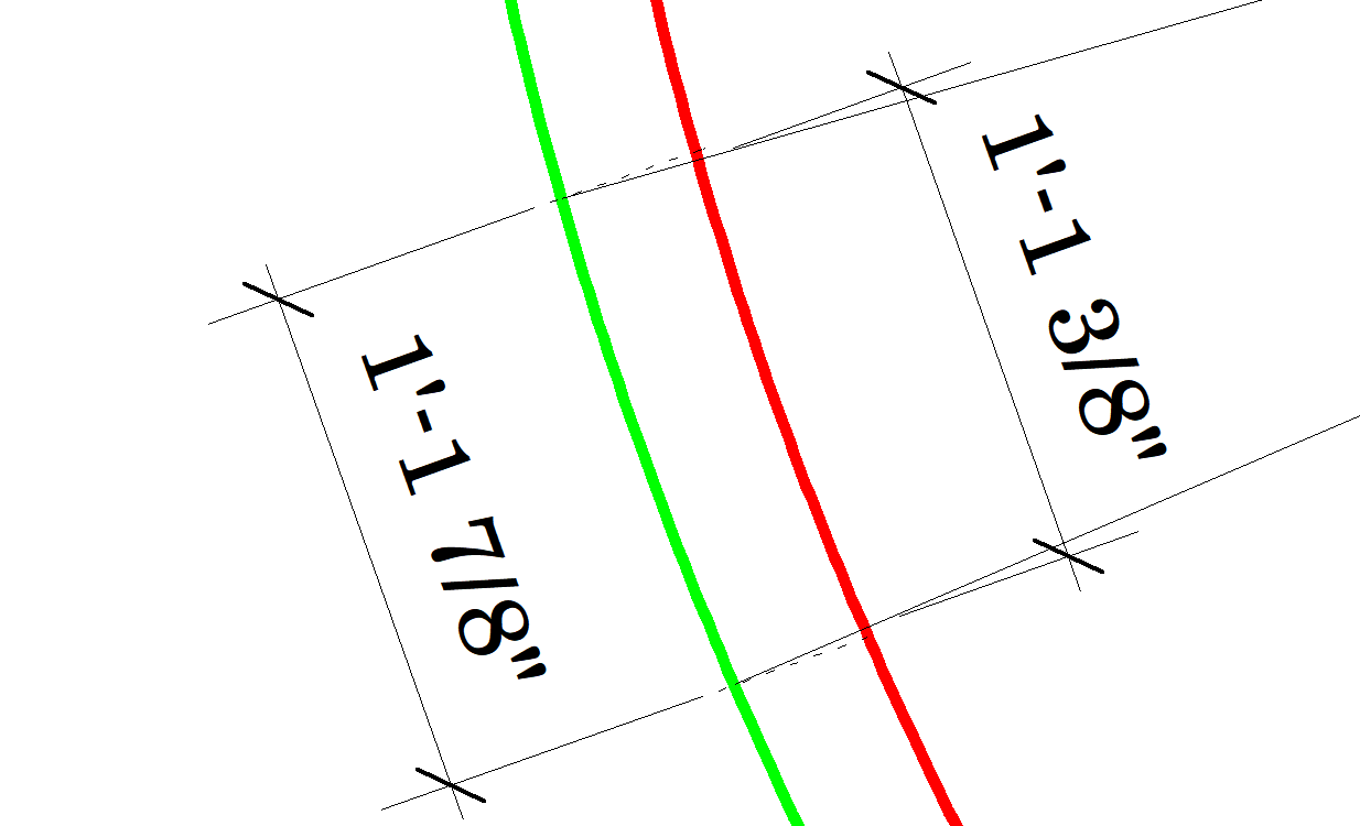
My take on the masking tape method. A piece of tape is placed on the model overlapping the preceding plank. It should lie flat simulating the plank you are going to make and not have any edge set, just laying naturally not forced. I then mark the edge of the preceding plank, the transom, the frames, especially frame 0, and the stem rabbet. Note that I marked the rabbet wrong in the following picture, it should be a curve. I then transfer the tape to a board and cut the shape of the preceding plank and the the opposite edge slightly oversize (say 2mm). I test fit the new plank on the model against the preceding plank and sand away any high points, rinse and repeat until the plank fits. I should then be able to use this plank as a template for the other side of the hull. (I will use the one below as a template for both sides while correction my 'rabbet' error). I then use the measurements (previous post) to shape the opposite edge.
-
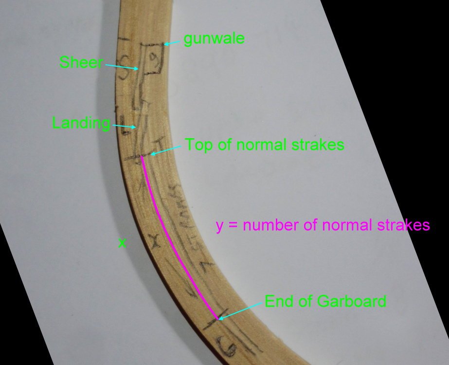
This post is a copy of something I posted in Tim's ( @oakheart ) build log, I'm repeating it here as I'm going to continue it a bit in the next post. ------------------------------------------------------------------------------ Right or wrong, this is what I do. First determine the maximum height up the stem of the garboard. This varies with the breadth of the plank. Cut a piece of plank the same breadth as the garboard short enough to sit in a straight section of the keel rabbet, use this as a spacer for a straight piece of balsa which reaches to the stem rabbet. That point is the maximum height up the stem of the garboard. At this point you can take measurements to get the curve of the garboard in the stem rabbet (put tick marks on the balsa and note measurements) but I tend to 'wing it'. Fit the garboard strakes. Now some maths, working out the breadth of the 'normal' strakes. Measure the distance from the garboard to the top of the sheer strake and subtract any 'abnormal' strakes, in the case of this launch remember to measure the outside of the planks not just along the frames as the planks will be narrower on the inside of the curve. Divide by the number of 'normal' strakes. If the result at the stem (or transom) is less than half the maximum breadth (at station 0) consider adding another strake. Note that at the stem the number is the length along the stem rather than the breadth of the plank. Repeat the calculations for each frame. And you should re-check your calculations after each strake. I then use the masking tape method to get the abutting shape of the next strake. I then shape and test, shape and test, shape and test, shape and test, shape and test the next plank. I then use the calculated widths to shape the other edge of the plank. (note the measurements noted on the plank in pic 3 above). Rinse and repeat.
-
Tim, note that it's not perfect. I've fitted the next plank (that shown in pic 3) and it doesn't quite look right, That curve, I think I have to reduce that 5.8mm to 4mm. Maybe, I'll ponder it. Edit: I left out that you should re-check your calculations after each strake.
-
I think that's a note to everyone. Right or wrong, this is what I do. First determine the maximum height up the stem of the garboard. This varies with the breadth of the plank. Cut a piece of plank the same breadth as the garboard short enough to sit in a straight section of the keel rabbet, use this as a spacer for a straight piece of balsa which reaches to the stem rabbet. That point is the maximum height up the stem of the garboard. At this point you can take measurements to get the curve of the garboard in the stem rabbet (put tick marks on the balsa and note measurements) but I tend to 'wing it'. Fit the garboard strakes. Now some maths, working out the breadth of the 'normal' strakes. Measure the distance from the garboard to the top of the sheer strake and subtract any 'abnormal' strakes, in the case of this launch remember to measure the outside of the planks not just along the frames as the planks will be narrower on the inside of the curve. Divide by the number of 'normal' strakes. If the result at the stem (or transom) is less than half the maximum breadth (at station 0) consider adding another strake. Note that at the stem the number is the length along the stem rather than the breadth of the plank. Repeat the calculations for each frame. And you should re-check your calculations after each strake. I then use the masking tape method to get the abutting shape of the next strake. I then shape and test, shape and test, shape and test, shape and test, shape and test the next plank. I then use the calculated widths to shape the other edge of the plank. (note the measurements noted on the plank in pic 3 above). Rinse and repeat.
-
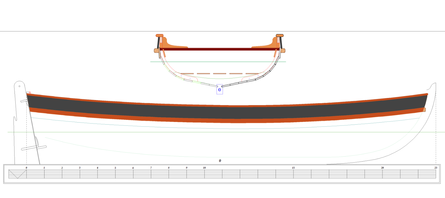
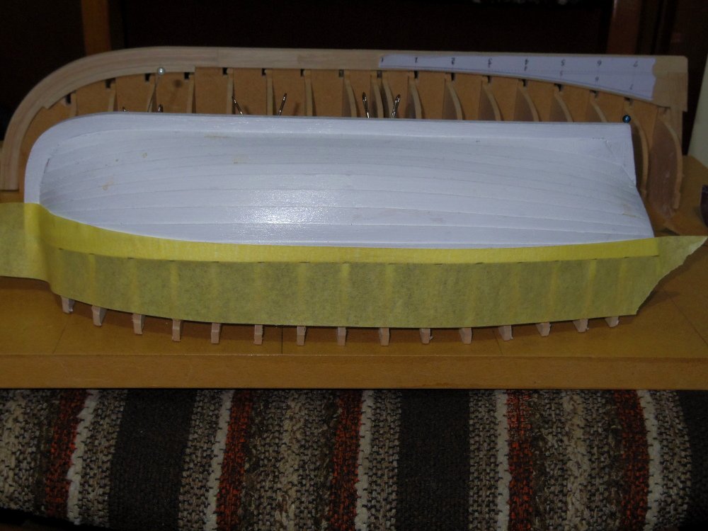
Garboards installed. Possible appearance:

-
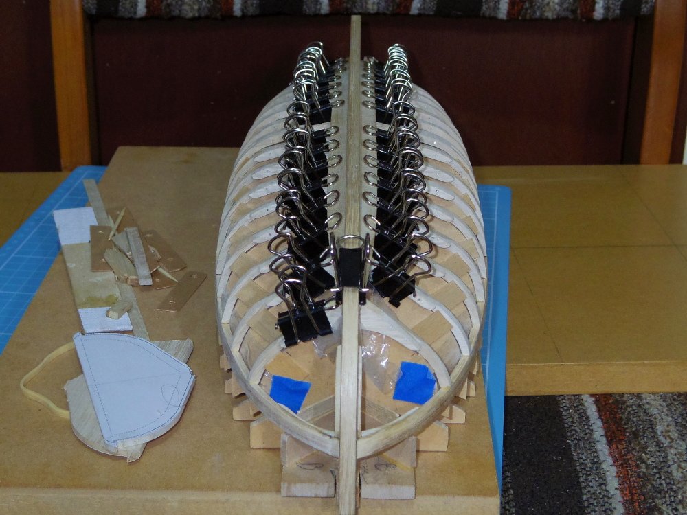
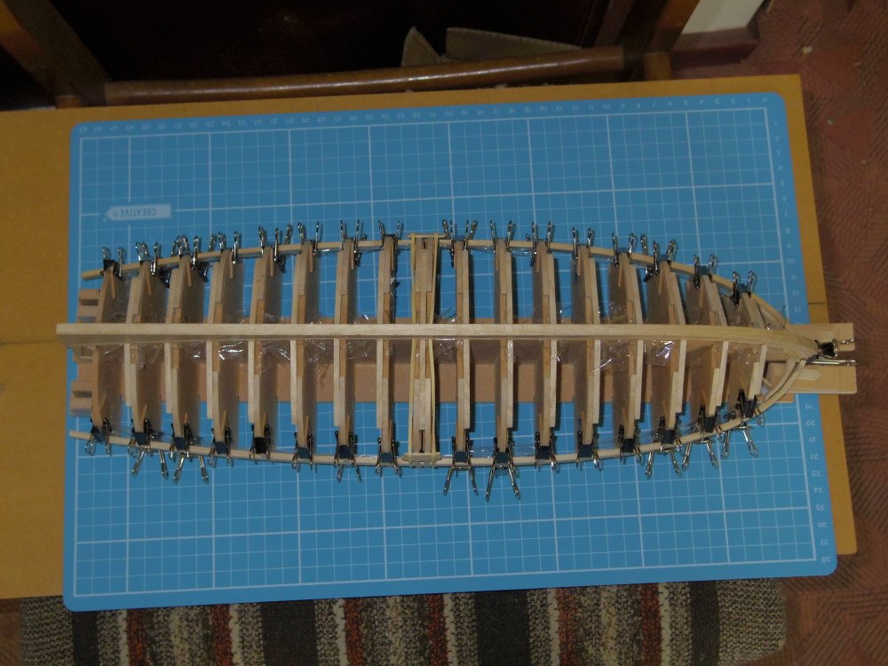
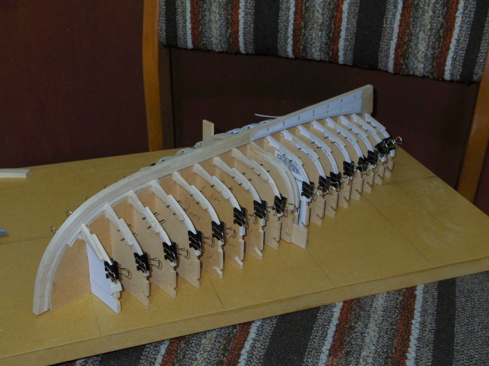
Well that bit is done (except frame 8). I think I'll let the glue cure overnight before the next step. It's a good thing I bought more clips the other day.
-
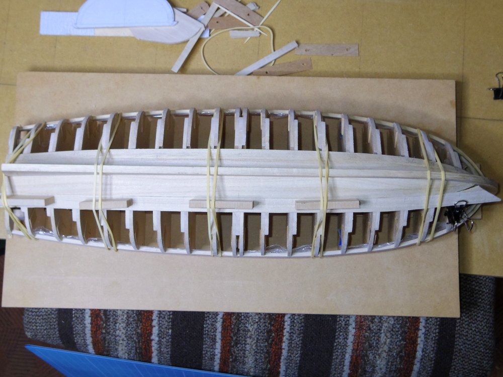
Gunwales bent and trimmed, breasthook shaped and glued to stem. Next I have to remove keel and frames and apply cling film anywhere glue might stick. Then put the frames back glueing them to the gunwale and the keel back glueing it to the frames. I think?
-
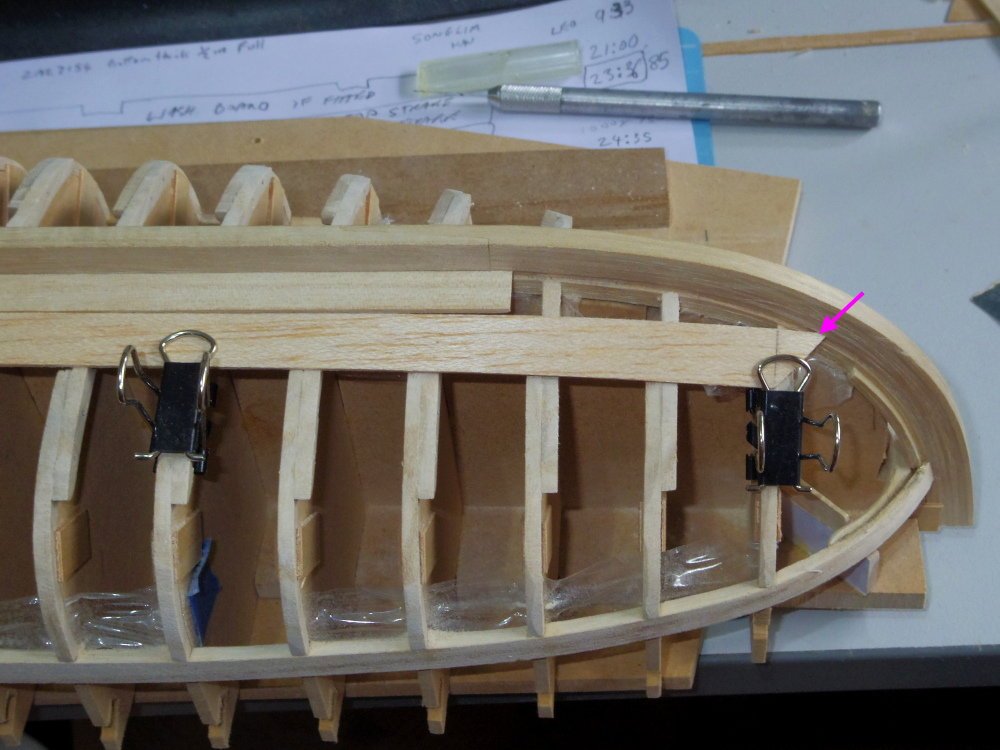
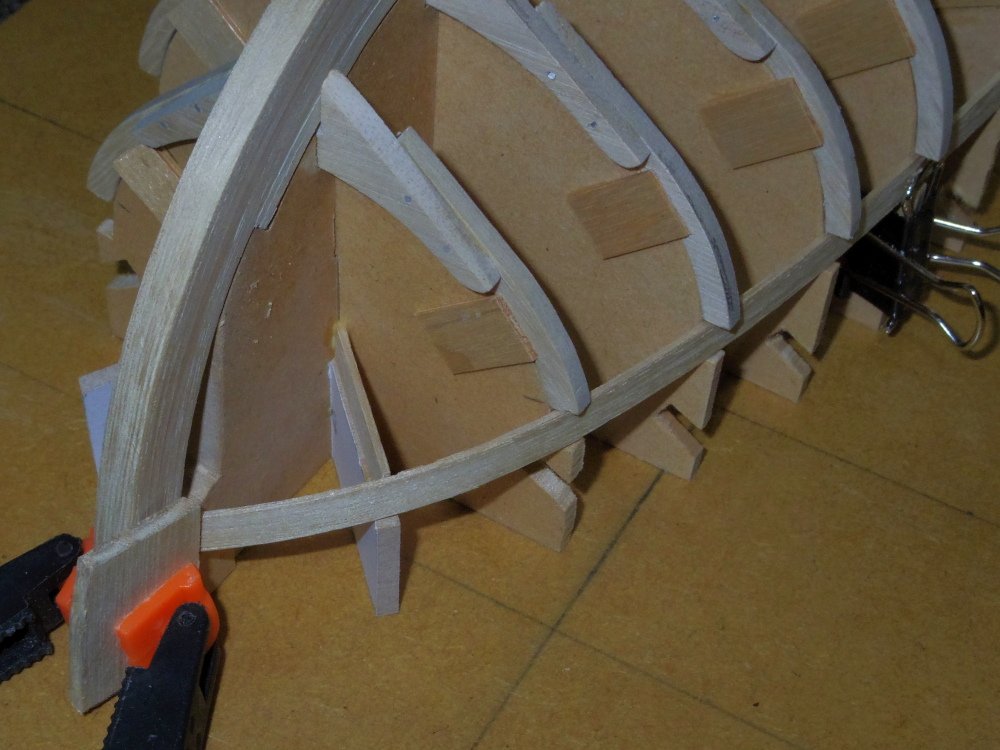
There's a few things you can try. First off, in a full size boat you can facet the frames as you have but this leaves a faceted interior, you can hollow out the inside of the planks to match the frames or you can use more skinnier planks. In a model you have the additional option of bending the plank around the frame either dry or wet. Clamping with rubber bands helps and using hollowed out balsa blocks helps more. Only clamp on or close to the frames.
-
While Allan created that thread with a question about oars he later realised it was more a discussion about the Bounty's launch and he changed the title and purpose of the thread. Your questions would indeed be welcome.
-
Allan, but it's a thread not a log. It pretty much is, we don't know much. I'll add drawings (or a link to them after I finish my build and tidy the drawings up).
-
Pushy pushy Not yet, gunwales to size and bent, breasthook shaped to take gunwales, gunwale glued to breasthook, frames glued to gunwales, keel glued to frames, transom glued to gunwales and keel then planking (I think).
-
Well, she probably doesn't look much different but the jig has been modified and glued, the transom rough shaped and the rabbet cut. Something went wrong with the printout of the notched strips for the jig and I finished up having to correct all the notches with a file which was a bummer as I was going to use them to square the moulds. Either the paper was too thin and slipped or it had excessive moisture.
-
So far so good? Should be all right, but you can measure the height of the step against the thickness of a plank. The next pair or two should go about the same as the last, then it gets a bit more interesting. Well done so far.
-
As Rodger said, seated something like this:
-
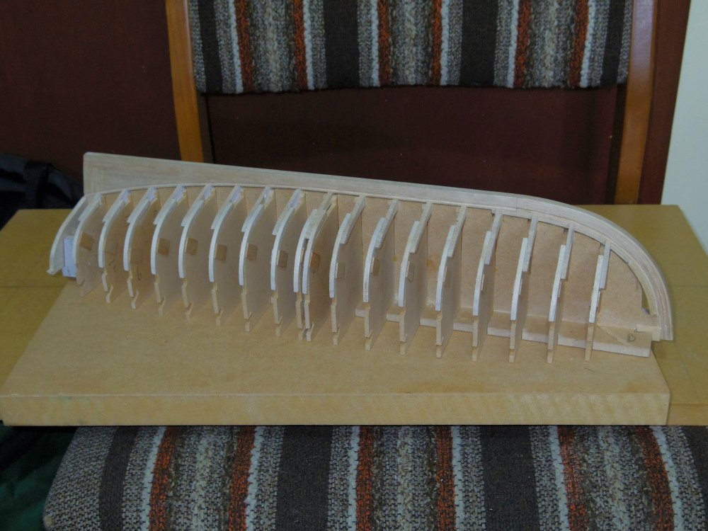
Still only the frames glued, still working out what I need on the jig before I glue it. I've added supports for the transom and breasthook/gunwale to the drawing and tabs to the moulds to support the frames while fairing.
-
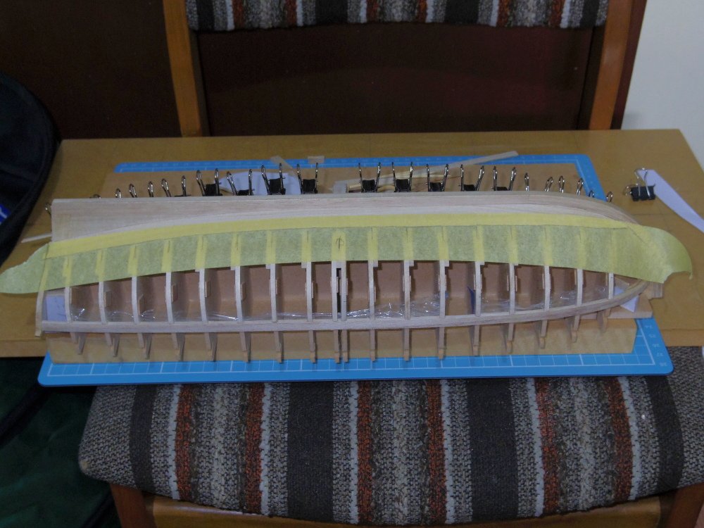
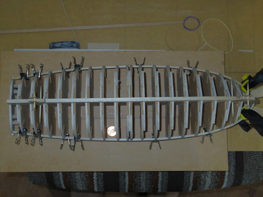
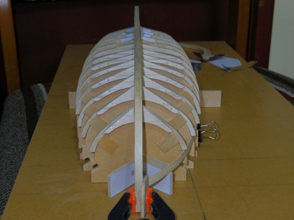
All frames glued up, just need the pins cut. Everything else just sitting there, not glued. It looks a little like a boat.
-
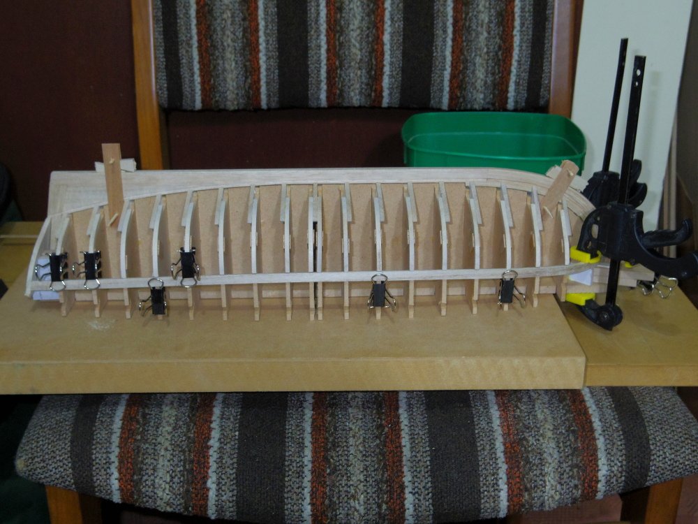
I realised that by forming the frames before the jig is glued it would be easier to clamp them using the moulds to set the shape. Note that the futtocks only follow the mould as far as the floor head.
-
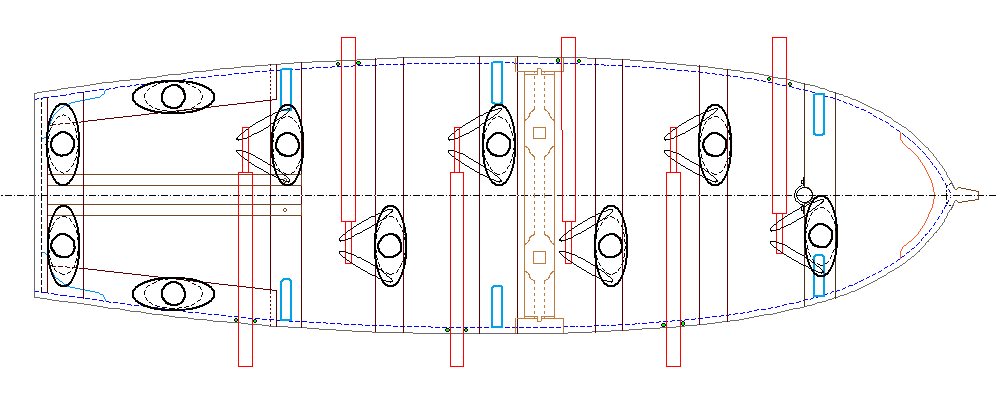
The shape of the hull Possibly the easiest way is the tape trick (see pic) the tape shouldn't have any kinks and should lay flat BUT it should approximate the outer surface of the plank you are trying to make (inner surface for clinker). Mark the edge of the previous plank at each frame and the stem and transom. Use the tape to make a template with your curves, use your calculated plank widths at each station to get the other edge.

-
This bit is easy to explain, the fan is just a way of marking off your divisions on your tick strip. On the fan mark your lines 0 through 8. Mark the measured distance on the tick strip. Hold one mark on line 0 and the other on line 8 (it doesn't matter how skewed it is) the other lines give your equal divisions. Remember that your planks will need to be slightly larger than that indicated by your division as you are measuring the inside arc. This is more relevant in real life but be aware.
-
It depends on what you are modelling. Fincham (ca1820) gives us this description. The transom in launches and clincher-built boats has its aft side on one surface, and well with the rake of the after part of the post; but in barges and pinnaces it is in general in two parts, the upper part lapping over the aft side of the lower, and projecting abaft it, to form a moulding on its lower part, well with the lower part of the land strake; and in addition to this mouldng, formed by the projection of its lower edge, one is likewise worked above by another projection, worked out of the upper piece, well with the lower part of the sheer or upper strake. The transom in launches and clincher-built boats are therefore always let in their thickness from the after part; and in barges, pinnaces, and yawls, from the fore part, it is in general fastened to the post with nails, in addition to the ring bolt and gudgeon. So the transom of almost any boat other than a Barge or Pinnace will look like one big slab but was probably made up of two or more pieces.
-
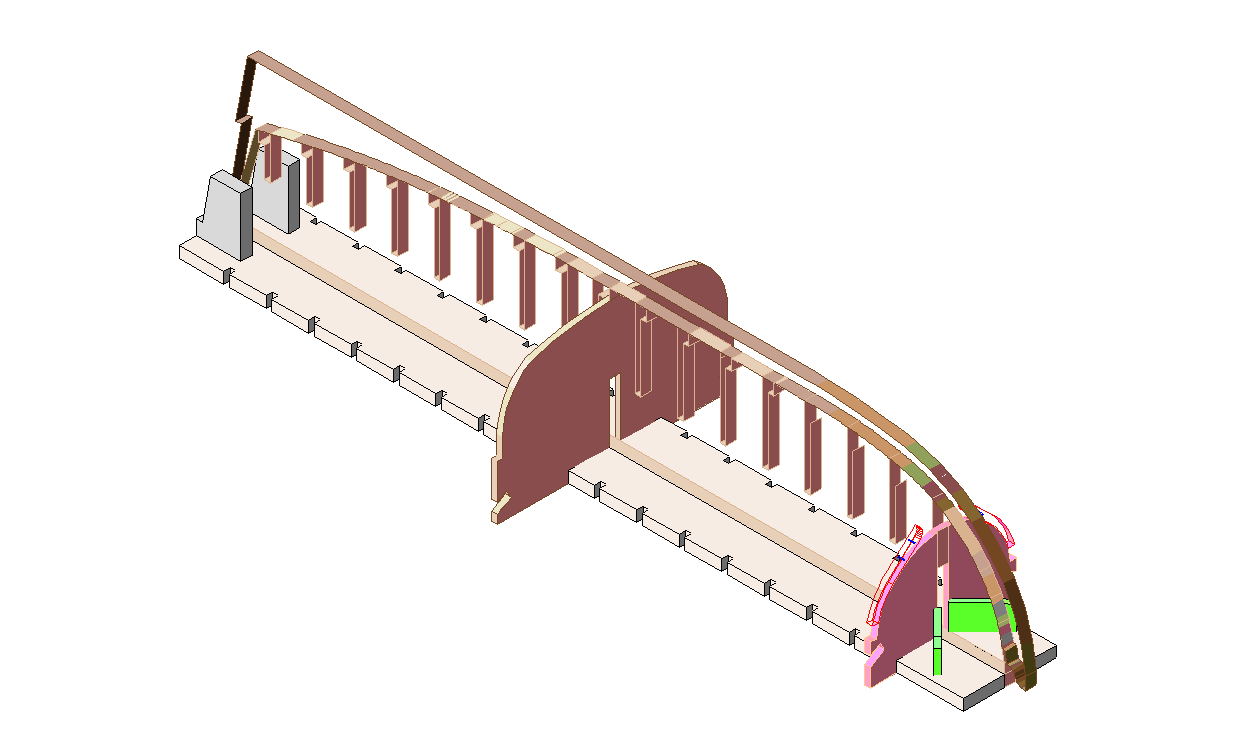
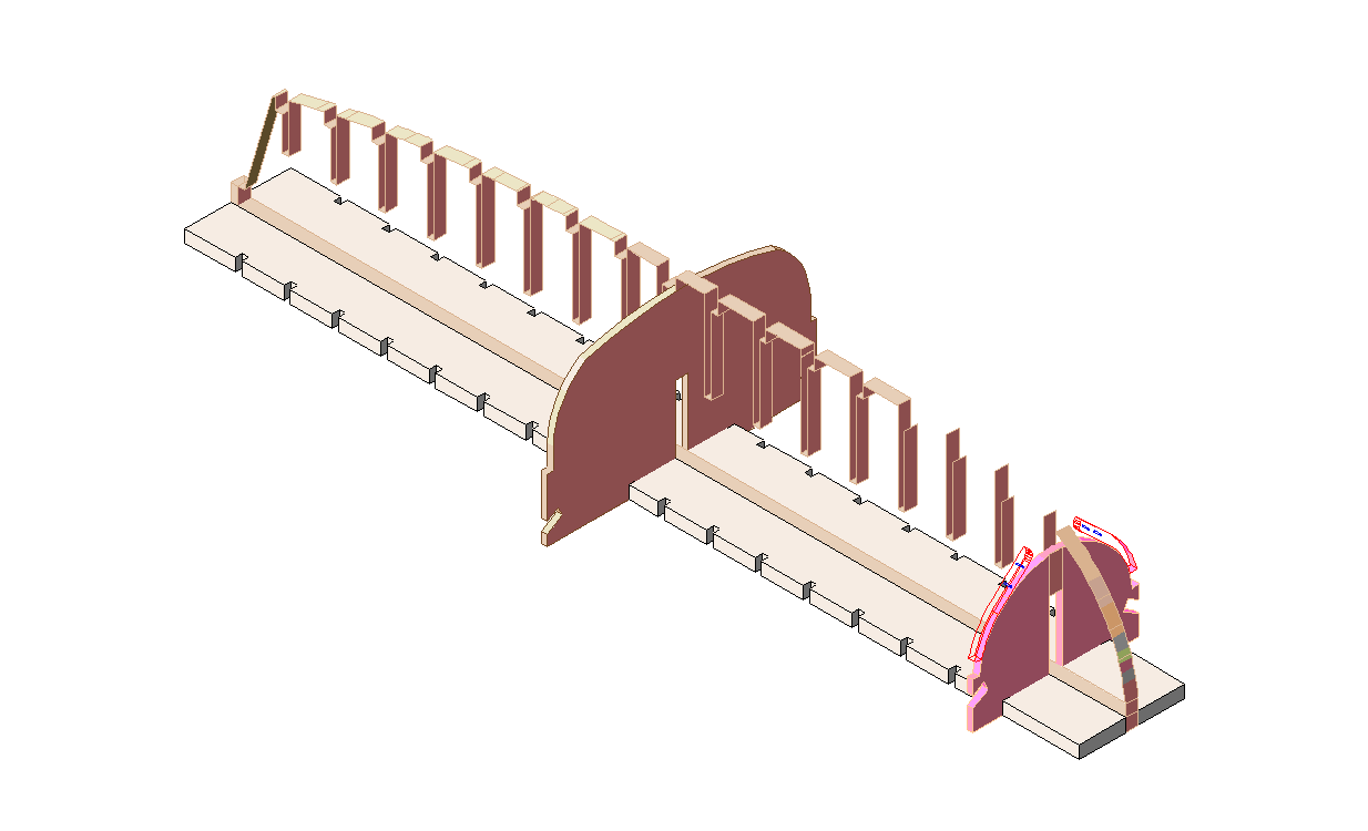
I've decided to make a change to the jig. Instead of just gluing it to a board as I have previously I'm going to glue a notched strip either side of the false keel and notch the moulds to fit. This should allow better access to the inside during construction. Please forgive my attempt at 3D, the false keel........:
-
In that case, not really. You're looking good. What does it look like inside? And good advice, I'm contemplating adding an additional mould (station i) to support the shape of the bow but it's not easy from a 2D drawing.
-
You are not alone. It's a very confusing subject. Sort of. I think. It won't be. Many of the descriptions you read are authors opinions stated as fact, even though there is often evidence to the contrary. Eg. there are contemporary sketches of six oared jolly boats. Function would have varied depending on the size of the ship and probably the Captains disposition. And as always, There will be exceptions. Fincham (ca1820) gives us this description. It's certainly not 100% correct but it's a start. The principal boats for attending upon ships are: launches, long boats, barges, pinnaces, cutters, yawls, jolly boats, life boats, and gigs or galleys. The launches, long boats, barges, pinnaces, and yawls, are carvel-built; and cutters, jolly boats, galleys, gigs, and life boats, are clincher-built. Launches are in general from 34 to 59 feet in length. They are for watering and carrying stores to the ship, and are sometimes armed and equipped for cruising at short distances; they are mostly fitted to carry one twelve-pounder carronnade, and sometimes fitted with swivel stocks. Long Boats are seldom or never employed for the use of British ships of war; they are sharper and wider than launches. Barges are generally 32 and 35 feet in length. These boats are for accommodation, pincipally for carrying flag officers and captains; and are lined and panelled above the thwarts, all fore and aft, that they may be richly decorated, if required. Pinnaces are 28 and 32 feet in length. These boats are for similar purposes as the barges, but to carry officers of less rank; they are not therefore fitted up in quite so neat a style, as they are lined and panelled no farther foward tnan the stern sheets. Yawls are in length 26, 25, 18, and 16 feet. These boats are for carrying light stores, provision, and passengers, to and from the ship. To the smaller class of ships,they answer all the purposes of a launch. Cutters, Jolly Boats, Galleys, Gigs, and life Boats are clincher-built, that they may be made as light as possible. Cutters are in length from 32 to 16 feet; they are used for various purposes that are common to ship's duty, though sometimes 32 foot cutters are supplied to ships instead of a barge, and used for the same purposes; and sometimes the shorter boats are called and used as jolly boats. Galleys are from 28 to 36 feet in length; they are used in enterprises and expeditions against the enemy, and against illegal trade. Gigs are in length from 16 to 27 feet; they are for swift rowing, and are supplied to ships when light boats are required. Life Boats are from 16 to 22 feet in length; they are for landing in surfs, performing enterprises and boarding ships, and for saving men that fall overboard,
- 24 replies
-
- 1
-

-
- Small boats
- cutter
- (and 2 more)
-
Make up your mind now as adding a rabbet will change the shape of your planks!