iMustBeCrazy
-
Posts
840 -
Joined
-
Last visited
Content Type
Profiles
Forums
Gallery
Events
Everything posted by iMustBeCrazy
-
 These days, factory produced mdf sheets come with four very square corners and four very straight sides. Even the smaller sheets. To make the above shooting board, cut two rectangles from mdf each with 1 square corner and two straight edges (1 long and 1 short) stack and clamp the pieces aligning the long edges with the top piece set down from the top edge of the bottom piece. Fix a fix a stop piece across the top of the bottom piece using the top piece to keep it square. Unclamp. The bottom should now have a stop which is square to it's long edge. Sounds really confusing but actually very easy once you grasp the idea.
 -
Lapwing 1816 Revenue Cutter
iMustBeCrazy replied to iMustBeCrazy's topic in CAD and 3D Modelling/Drafting Plans with Software
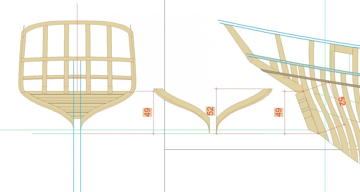
3D Transom (MDF): Note that when making any part from the drawings you must make sure that the part is drawn 'square on', those that aren't such as the transom, counter, cant frames etc. need to be corrected. For example the transom viewed from the stern appears to be 49 inches high but as shown is is actually 52 inches. To correct this, the drawing from the stern needs to be stretched vertically by 52/49ths (1.0612244). Also you need to allow for any bevelling which may not be shown. In this case, the fashion pieces are wider on the forward side and the bevel is shown on the corrected drawing. Yes, I forgot the bevel the first time.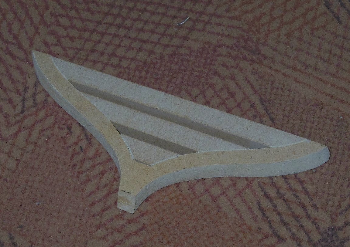
-
Lapwing 1816 Revenue Cutter
iMustBeCrazy replied to iMustBeCrazy's topic in CAD and 3D Modelling/Drafting Plans with Software
Current state of play:
-
Lapwing 1816 Revenue Cutter
iMustBeCrazy replied to iMustBeCrazy's topic in CAD and 3D Modelling/Drafting Plans with Software
Thanks druxey, currently 8 inches, probably only need 4 or 5. I guess for even spacing top and bottom. I'll fix them. -
Lapwing 1816 Revenue Cutter
iMustBeCrazy replied to iMustBeCrazy's topic in CAD and 3D Modelling/Drafting Plans with Software
Well, it doesn't help my headache but it certainly helps. For one thing it shows I forgot the fashion piece. Doh! Still need to rework the side counter timbers and perhaps the counter timbers:
-
Lapwing 1816 Revenue Cutter
iMustBeCrazy replied to iMustBeCrazy's topic in CAD and 3D Modelling/Drafting Plans with Software
Thanks for those Bob, slowly piecing it together in my head but it's still mostly imagineering. -
Lapwing 1816 Revenue Cutter
iMustBeCrazy replied to iMustBeCrazy's topic in CAD and 3D Modelling/Drafting Plans with Software
Still going. Trying to work out the structure of the stern, very little info to work on. Any ideas? Any references? Re-did the frames to include decks, it will make life easier later. I wonder, what else am I missing.
-
Lapwing 1816 Revenue Cutter
iMustBeCrazy replied to iMustBeCrazy's topic in CAD and 3D Modelling/Drafting Plans with Software
Work continues, Disposition of the Frame: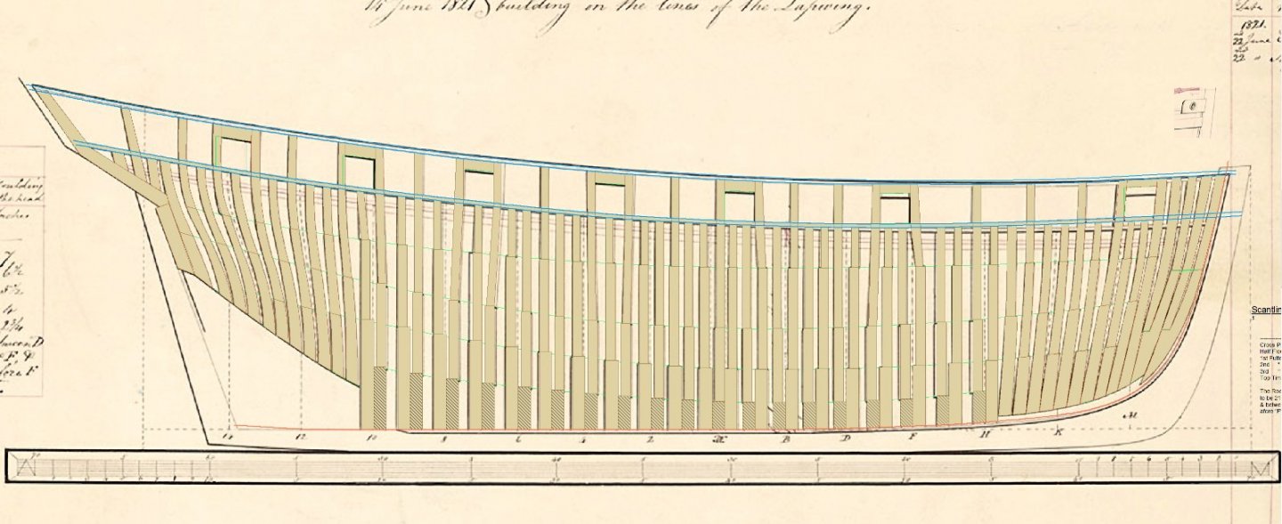
-
Lapwing 1816 Revenue Cutter
iMustBeCrazy replied to iMustBeCrazy's topic in CAD and 3D Modelling/Drafting Plans with Software
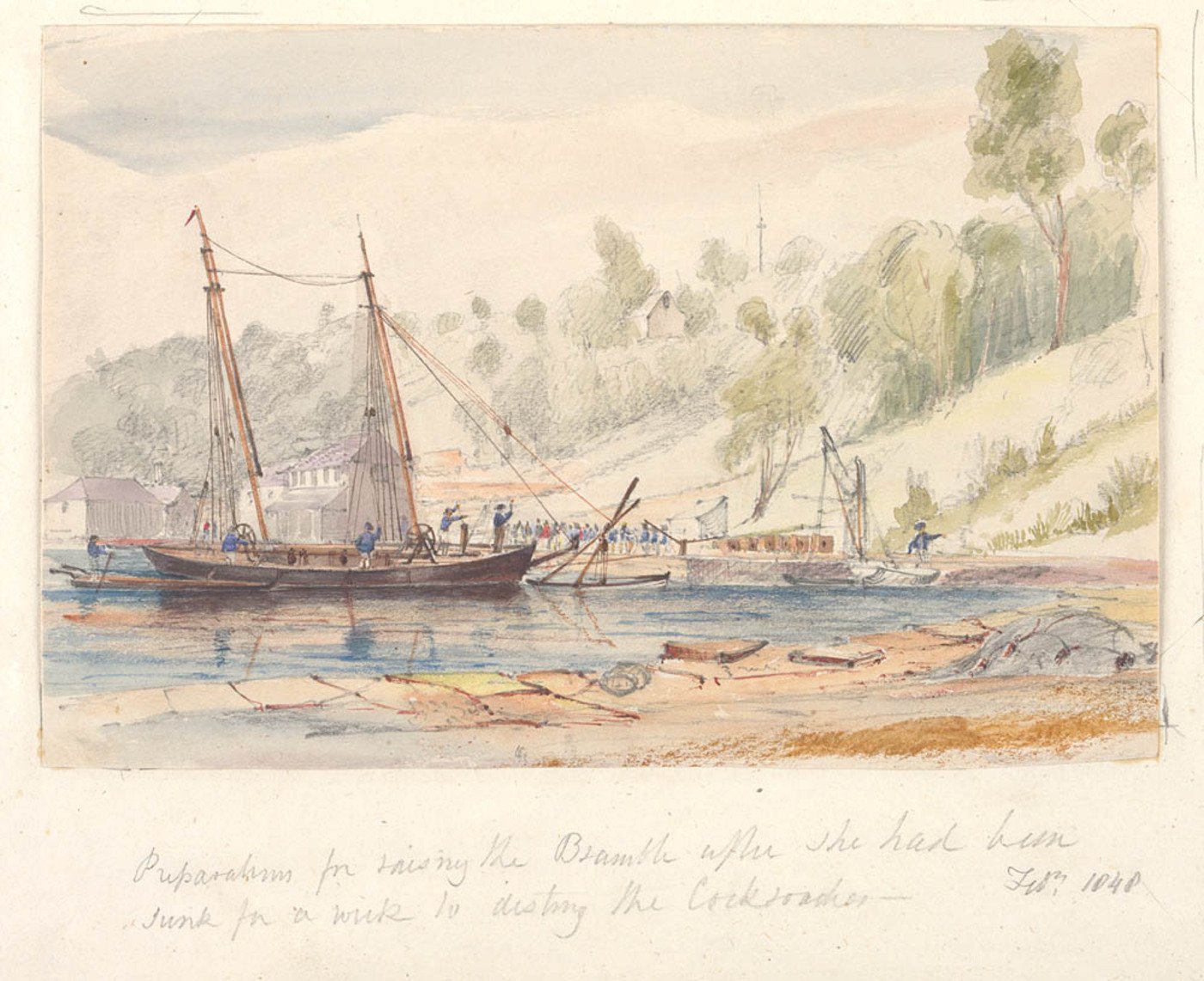
Yes. And that cockroaches can be really hard to get rid of -
Lapwing 1816 Revenue Cutter
iMustBeCrazy replied to iMustBeCrazy's topic in CAD and 3D Modelling/Drafting Plans with Software
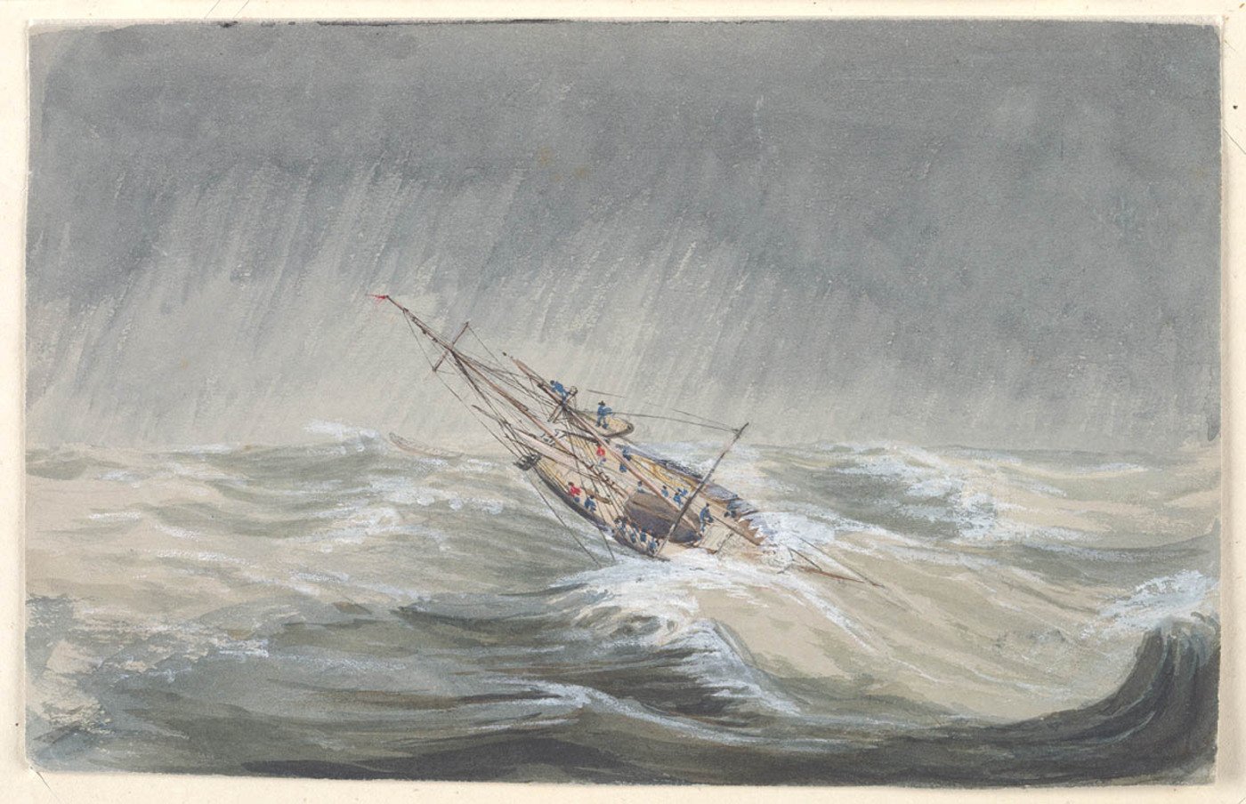
Some sketches of Bramble taken from Owen Stanley - Voyage of H.M.S. Rattlesnake


-
Lapwing 1816 Revenue Cutter
iMustBeCrazy replied to iMustBeCrazy's topic in CAD and 3D Modelling/Drafting Plans with Software
It's certainly not final but I should have pointed out that whereas the others are every second station, as usually depicted, that one is station 15, only a single step from the preceding station (14). It's a bit of a guesstimate to try to fill in the huge gap between station 14 and the transom. Same goes for the first station at the bow. If I could get out and buy some cardboard I would mock it up to get a better feel for the lines. But, thank you, all criticisms and suggestions gratefully accepted! -
Lapwing 1816 Revenue Cutter
iMustBeCrazy replied to iMustBeCrazy's topic in CAD and 3D Modelling/Drafting Plans with Software
G'day Tony, Actually, I didn't. I haven't delved very deeply into all the sisters, half-sisters, cousins and nieces, there's too many. Cutter then Schooner is the way I see it, the Cutter painting is dated 1840 and the sailplan 1841 so that works. I guess I will have to investigate Bramble further. -
Lapwing 1816 Revenue Cutter
iMustBeCrazy replied to iMustBeCrazy's topic in CAD and 3D Modelling/Drafting Plans with Software
I needed a break from staring at lines on a screen. Midship frame 1:24 in MDF. 1:24 is massive! 1:48 might be too fiddly for PoF for me, top timbers would be like matchsticks.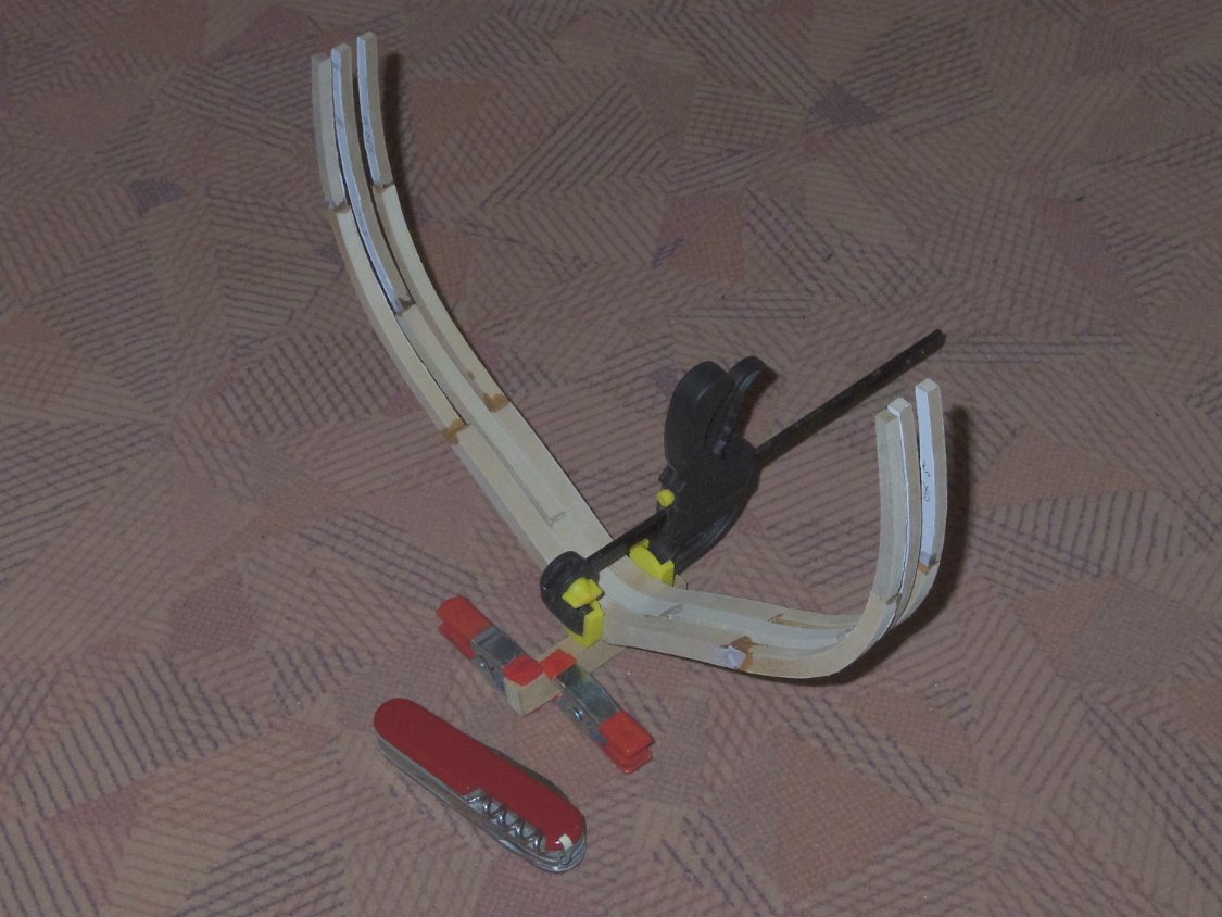
-
Lapwing 1816 Revenue Cutter
iMustBeCrazy replied to iMustBeCrazy's topic in CAD and 3D Modelling/Drafting Plans with Software
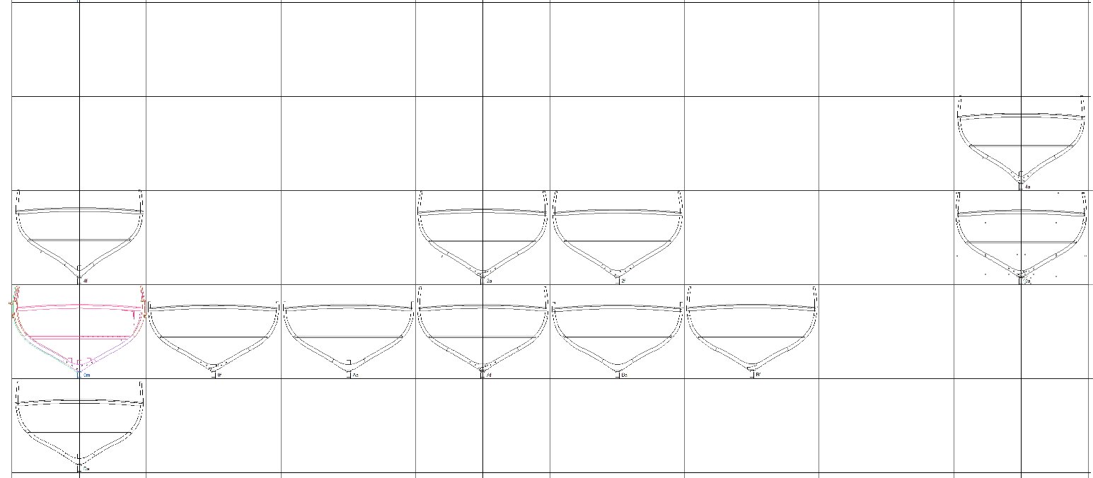
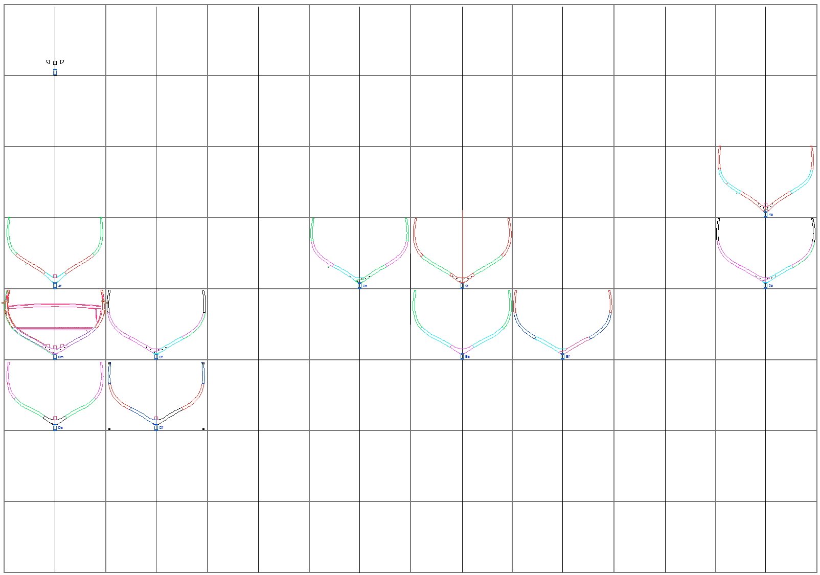
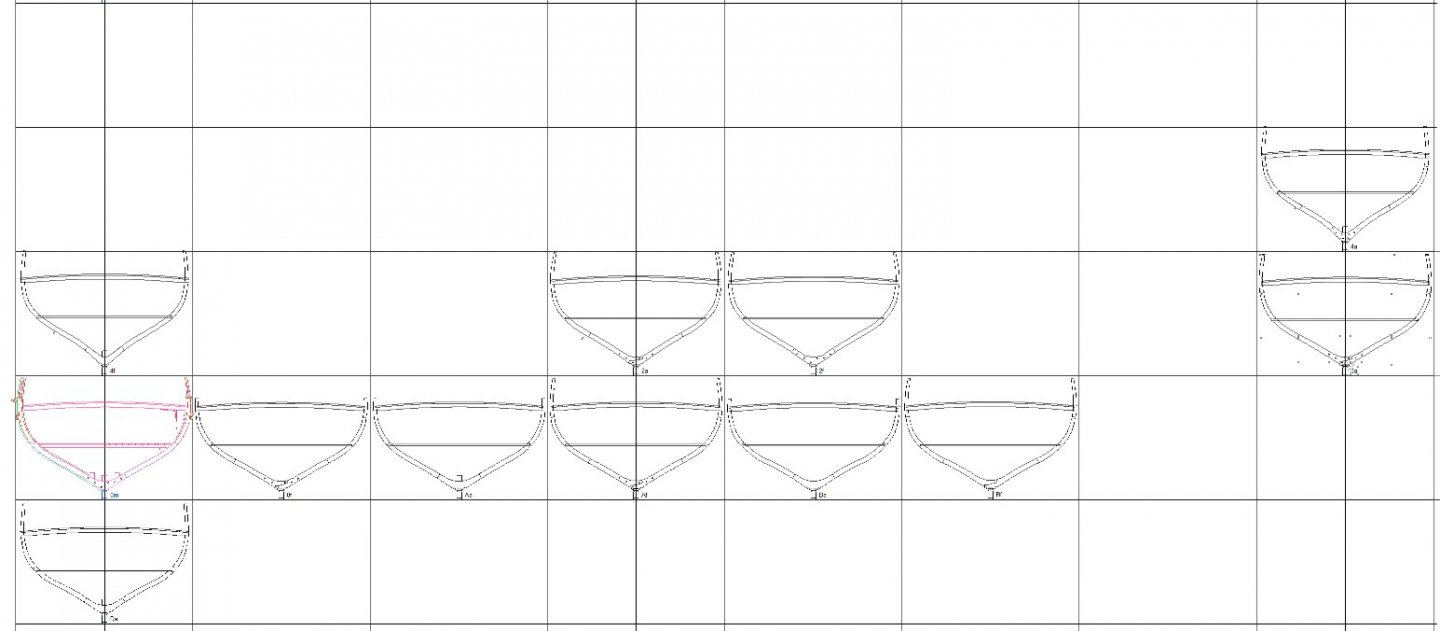
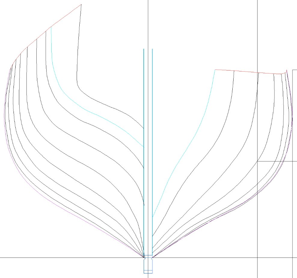
Ok, new sheer plan based on the disposition of frames for Speedy (1828): Lots of work to go, all of these squares need to be filled (this is only stations D, B, 0, 2 and 4):
-
Lapwing 1816 Revenue Cutter
iMustBeCrazy replied to iMustBeCrazy's topic in CAD and 3D Modelling/Drafting Plans with Software
Unless you compare it to the crews. -
Lapwing 1816 Revenue Cutter
iMustBeCrazy replied to iMustBeCrazy's topic in CAD and 3D Modelling/Drafting Plans with Software
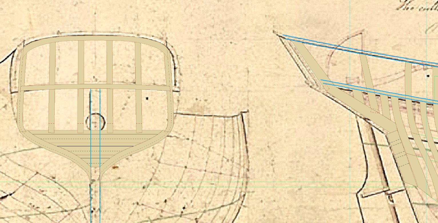
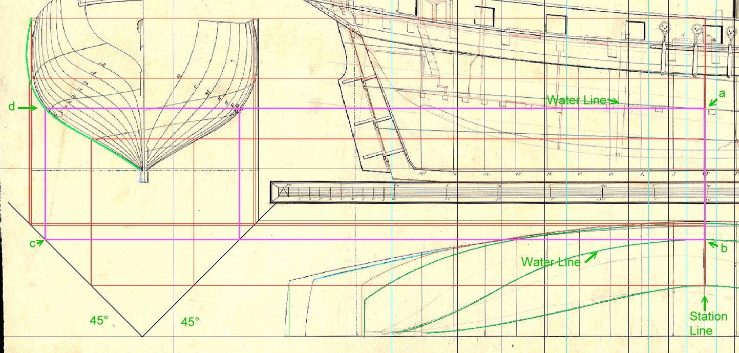
Arrrrggggg!!!! Three steps backwards, after drawing up the frames at station 2 I remembered ZAZ6425 has two sets of station lines, then I realised that the sheer plan is based on station lines that have no relationship to frames. While this wouldn't matter for a PoB build I want these drawings to be able to be used for PoF. So I have to re-draw the station lines and sheer plan. Of course I don't have a table of offsets, but fortunately there is a shortcut I can take: By drawing a set of rectangles like the one in pink below, where points a and b are on the intersections of a station line and a reference line (in this case a water line) and point c touches the 45° degree line under the sheer plan, point d is the station line / water line intersection on the sheer plan. Unfortunately I don't have many reference lines on this drawing, basically just 4, so I have to base the shape of the 'frame' on those next to it.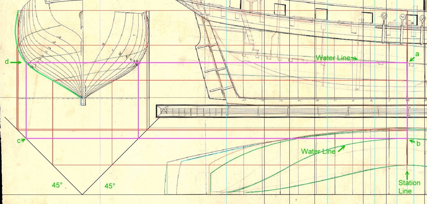
-
First they became a fence, did you notice the latitude of Macquarie Harbour? 42° South, that's roaring forties. You might like this one then, Port Arthur the main penal settlement. https://nla.gov.au/nla.obj-1961910992/view?sectionId=nla.obj-1965082829&partId=nla.obj-1961946782#page/n26/mode/1up
-
An account of Macquarie Harbour and Sarah Island: https://nla.gov.au/nla.obj-1956722306/view?sectionId=nla.obj-1965094843&partId=nla.obj-1961882571#page/n40/mode/1up Continuation: https://nla.gov.au/nla.obj-1956083842/view?sectionId=nla.obj-1959466639&partId=nla.obj-1956120316#page/n18/mode/1up
-
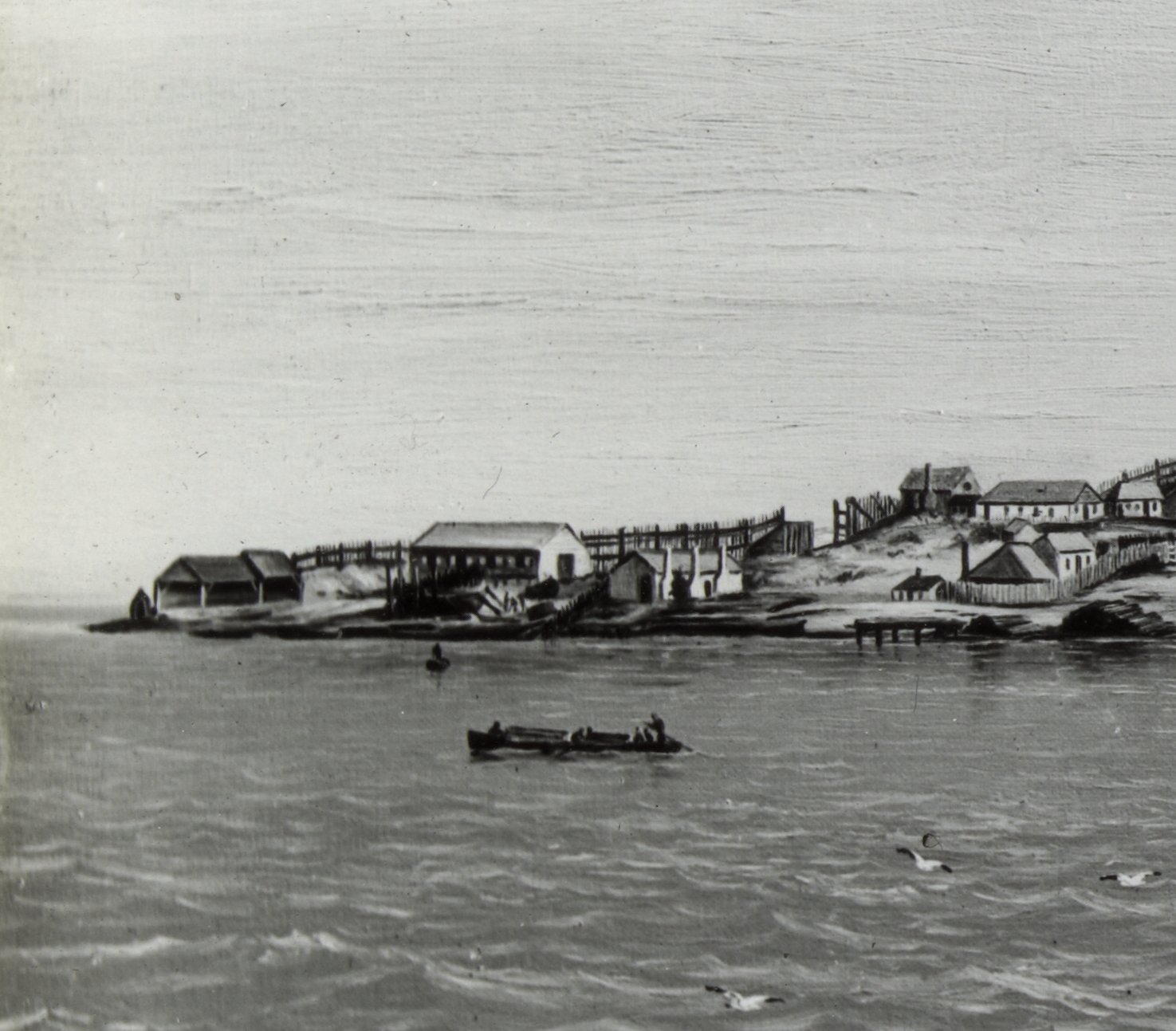
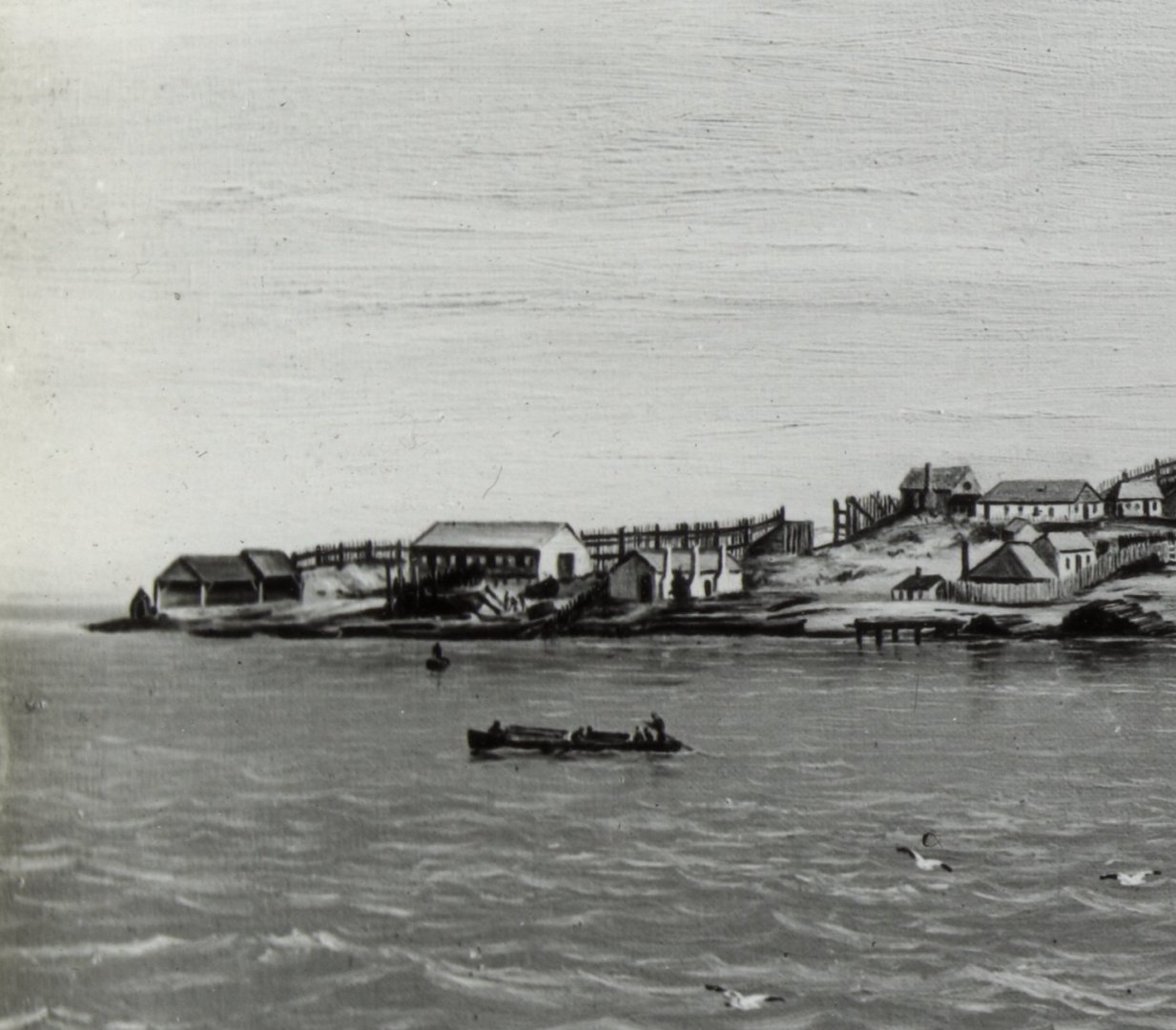
Ship building, Sarah Island 1832. The fence in the background is a windbreak the length of the island.
-
Apparently yes, I was aware of shipbuilding at Port Arthur but I assumed small vessels. It seems more likely that the 74 gun was probably built at Sarah Island in Macquarie Harbour on the west coast. http://www.ourtasmania.com.au/devonport/sarah-isld.html If I have it right, the shipyard was to the right of the bridge. A nearly completed Brig was stolen from there by 10 convicts and sailed to Chile but the amazing part is that they got it through 'Hells Gate' the entrance to Macquarie Harbour. https://viewer.slv.vic.gov.au/?entity=IE740422&mode=browse The entrance is just this side of the lighthouse.
-
Lapwing 1816 Revenue Cutter
iMustBeCrazy replied to iMustBeCrazy's topic in CAD and 3D Modelling/Drafting Plans with Software
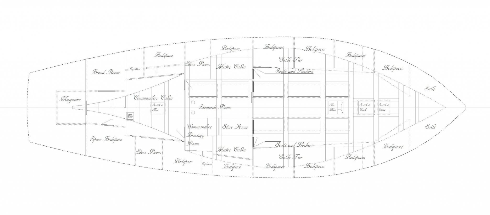
Lower deck done (I think). It was interesting trying to work out the original Lapwing layout from under the revisions for Speedy, luckily ZAZ6347 for the Basilisk seems based on the original Lapwing. Somehow the squeezed 10 passengers in on the trip to Australia and I have a copy of an advert for 'First Class passage'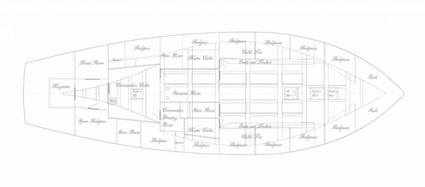
-
Lapwing 1816 Revenue Cutter
iMustBeCrazy replied to iMustBeCrazy's topic in CAD and 3D Modelling/Drafting Plans with Software
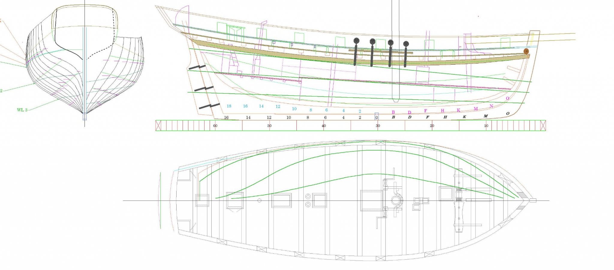
Deck done for now. Also tidied up those reference lines.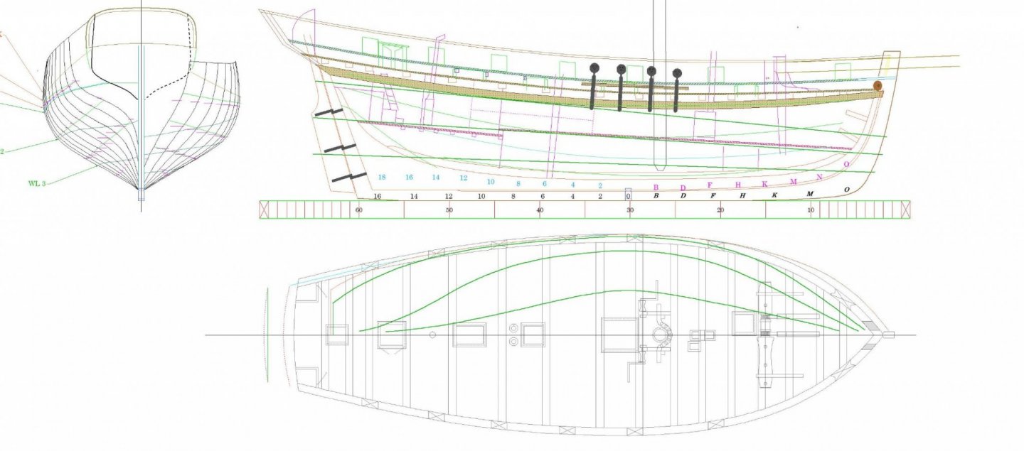
-
Lapwing 1816 Revenue Cutter
iMustBeCrazy replied to iMustBeCrazy's topic in CAD and 3D Modelling/Drafting Plans with Software
Sail plan, just for something different. EDIT: Sailplan updated, now includes spar dimensions an a scale. Please let me know of any spelling or terminology issues. Lapwing Sailplan 1in48.mc.pdf -
Lapwing 1816 Revenue Cutter
iMustBeCrazy replied to iMustBeCrazy's topic in CAD and 3D Modelling/Drafting Plans with Software
A bit more progress. Deck almost done, just winches to do I think. I realise now that I should have drawn all those station lines and guide lines on different layers so I could turn them off, live and learn.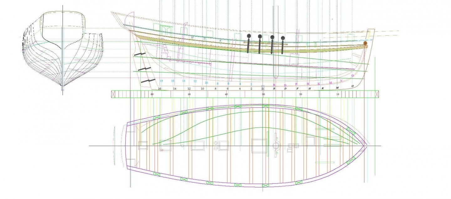
-
All I know is it's called 'nesting'. As for the stern, I don't blame you. I'd been looking at these drawings for months and didn't see it, then all of a sudden there it was.