iMustBeCrazy
-
Posts
976 -
Joined
-
Last visited
Content Type
Profiles
Forums
Gallery
Events
Everything posted by iMustBeCrazy
-
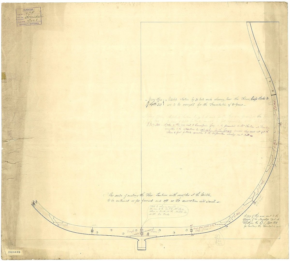
 Probably a little earlier from what I see, ZAZ6163 (Transit 1809) seems a little confused but is still scarphs and maybe chocks while on ZAZ6446 (Quail 1816) it seems firmly established. So perhaps somewhere between those dates. But 'about 1820' still fits.
 -
druxey, probably smaller than you're thinking but all(?) the frame drawings I've seen for revenue cutters and similar sized vessels (mostly 1800s) carry text such as "The timbers are to have square heads and heels coaked together as represented at 'A'; but where a square head and heel cannot be formed they are to be scarfed as represented at 'B'." None show chocked joints. NB: Coaked - joined with a round or square dowel.
-
No real opinion, just a couple of examples:
-
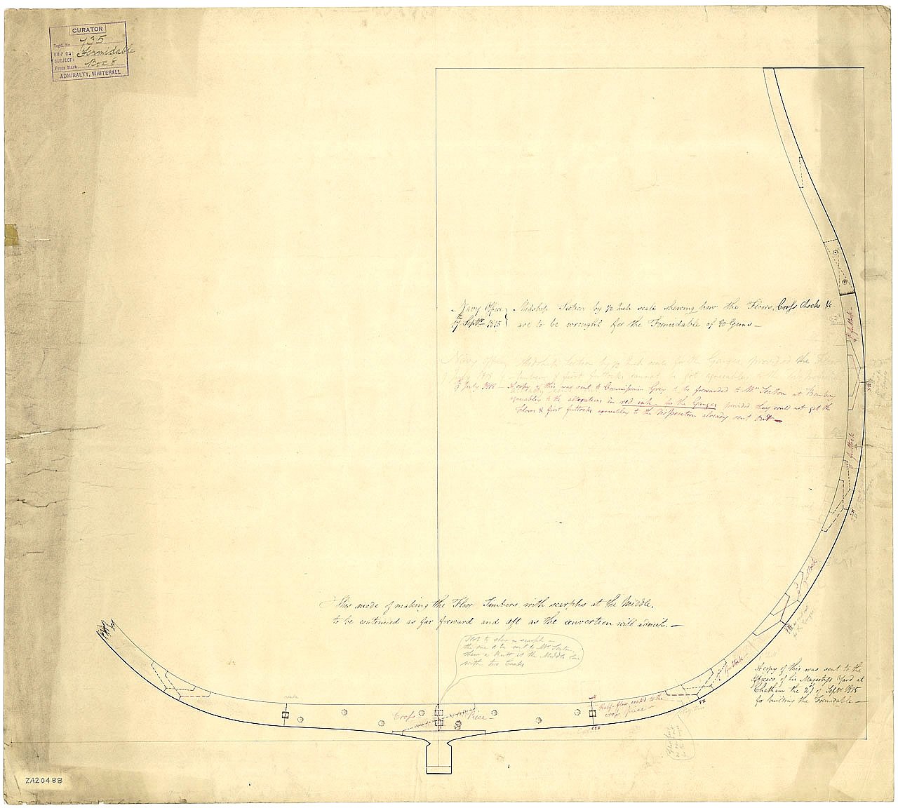
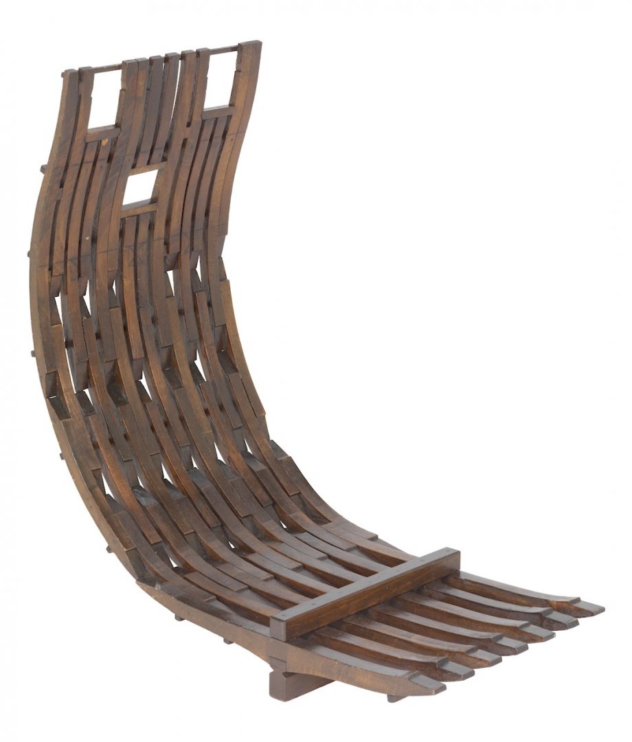
Perhaps more often 'Floor' or 'Floor Timber', the pieces marked with an 'x'. They're beaut's aren't they, they read 1, 3, 5, 7, 9, 11, 13, 15, 17, 19, 21, 23,25, 27, 29. But no '0'.
-
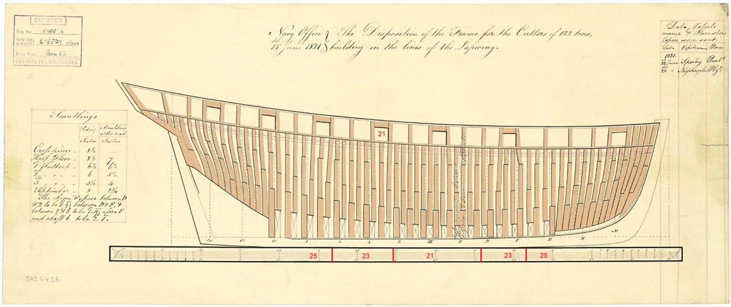
Don, another thing to note is the the 'frame pair' at station 0 was often a triple or single frame not a pair. This reversed the way the frames in the pairs were arranged so that the same half was always closest to station 0. Speedy (cross piece of each pair closest to station 0): Aquilon (NON cross piece of each pair closest to station 0):
_(also_spelt_Aquillon_or_Acquillon)_RMG_J7958c.png.d11c836f5aa79ec7b1f8ce72c2781686.png)

-
Hey, it gets the point across admirably. I suspect this would give uneven loading on the breeching lines but others will know better.
-
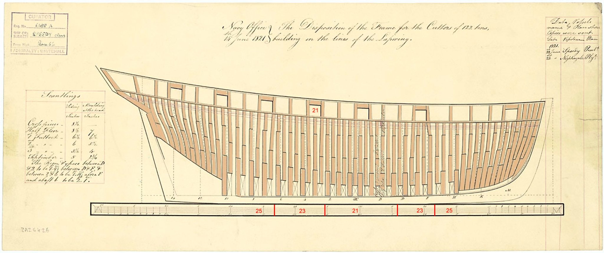
Don, sometimes it's just messy. This is Speedy 1828, the R&S varies 25", 23", 21", 23", 25" while the ports are a nominal 21". It just cannot be done neatly, I tried and failed. The futtocks have to be stepped and or lean to suit the spacing of the gun ports.
-
These days it might be closer to the truth to say a boat can be transported by road while a ship can't.
-
Body plan line
iMustBeCrazy replied to Don Case's topic in Building, Framing, Planking and plating a ships hull and deck
I agree. The green rectangles show the relationship to each end of the transom. The blue one demonstrates the relationship of a station line/waterline intersection.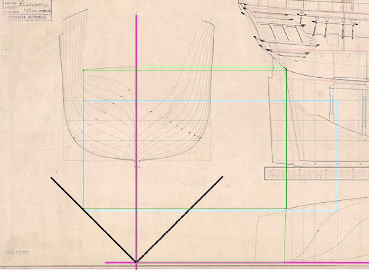
-
Sloping deck
iMustBeCrazy replied to Don Case's topic in Building, Framing, Planking and plating a ships hull and deck
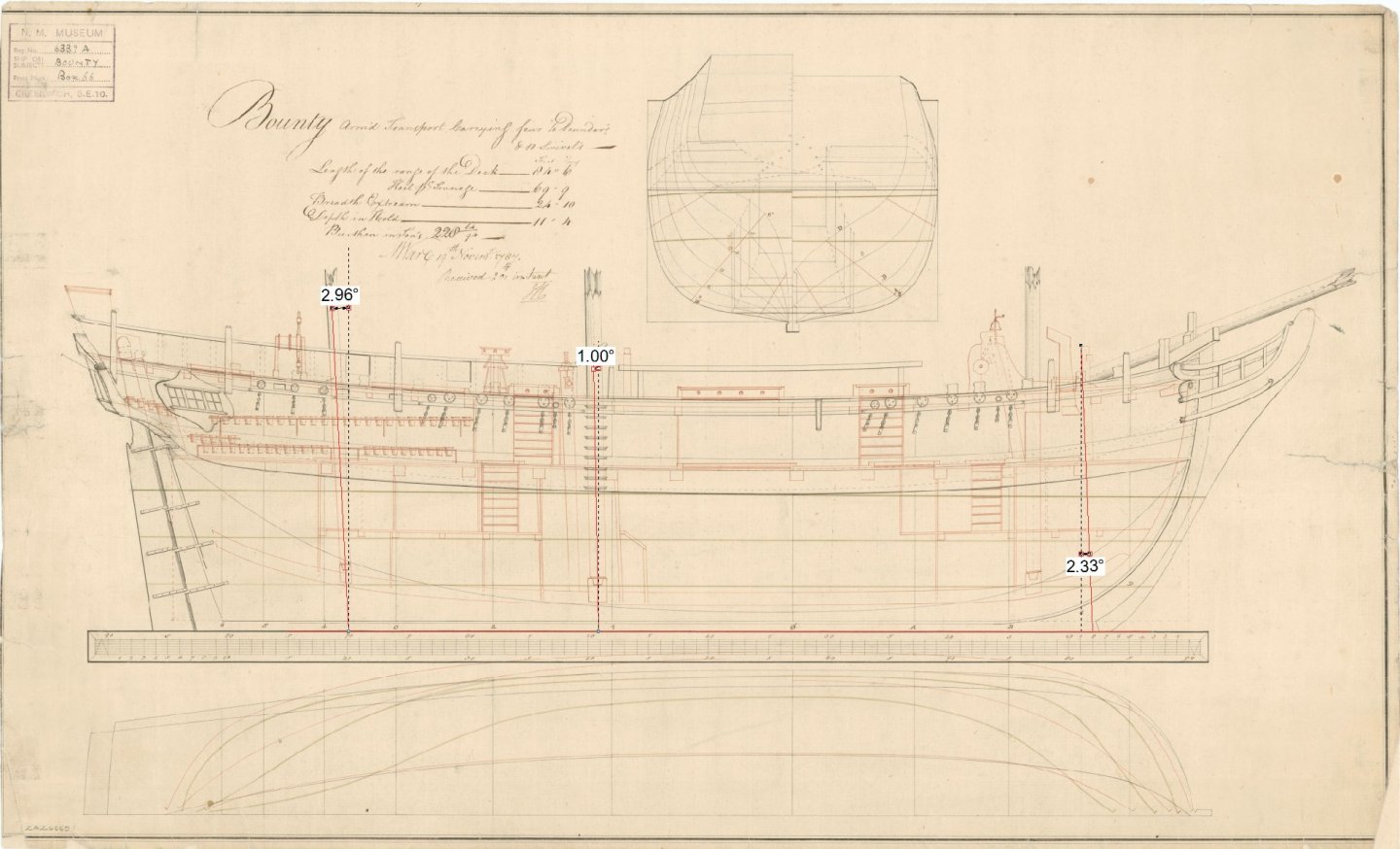
Don, it seems to start at the mast, so about 16'. This might make it clearer.
-
Probably the safest way to answer this is that there are tables giving standardized sizes but that size varied by boat type, boat length and thwart position/type.
-
The various tables of scantlings for boats available break down thwarts in to 'main', 'after', 'fore' and 'loose' which might imply that the 'main', 'after' and 'fore' are not loose and most likely have knees. The transcripts of the Bounty mutineers trial include statements the the knees and bolts for both the launch and large cutter had to be retrieved from the chests of the carpenter and carpenters mate. These chests weren't all that big so perhaps only the knees of the main thwart (or thwarts in larger boats) were removable.
-
Ah well, the lines are my work No problem.
-
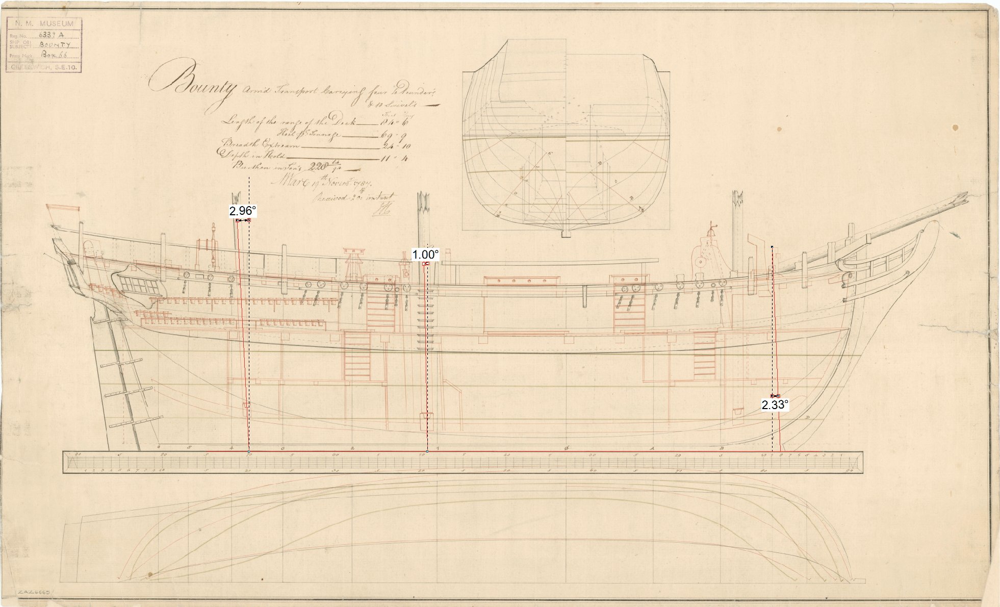
This is what I get: Do you have this drawing? https://commons.wikimedia.org/wiki/File:Admiralty_Sheer_Draught_Ship_Plans_-_HMS_Bounty_RMG_J2028.png
-
Some time after 1660. And 1797:
-
I didn't mind it except they never had enough extras. Hornblower never seemed to have more than a dozen crew no matter what sized ship he had and 20-30 'Lobsters' marching off to invade France wasn't very convincing.
-
I've been binge reading recently, finished the Aubrey-Maturin series and up to Jesters Fortune (book 8.) in the Alan Lewrie series. Alan Lewrie was basically blackmailed by his father into signing on as a midshipman, he never dropped below that rank. Aubrey however signed on as a mid but was 'set before the mast' for a time for smuggling a girl on board. It was a morally questionable period of time. I mean, you could kill someone 'defending your honour' even if you didn't have any.
-
Stoves/Ovens on ships in the 1600s and Onward
iMustBeCrazy replied to acaron41120's topic in Nautical/Naval History
Well, the preview says it will work, so here's what happens when I hit 'submit reply'. -
I guess the true answer would be 'it varied'. But for the davits and falls the Harriet model would provide a good example https://collections.rmg.co.uk/collections/objects/66775.html For the boat, a simple eye bolt and ring through the stern post and stem or a ring under a clamping plate for heavier boats. (Both above the CoG).
- 1 reply
-
- 3
-

-

-
Historical Fantasy. Oh, and Heresy.
iMustBeCrazy replied to Gazzarian's topic in Nautical/Naval History
I wish I had the skills you think I have The Lapwing proves your point, launched in 1816 as a Revenue Cutter, sailed to Australia in 1853 under private ownership carrying the new owner and family to Adelaide before being sold and used as a cargo vessel. Wrecked in 1856 after the Harbour Master had a larger vessel hooked to the same mooring which later dragged beaching both ships. The Lapwing broached and was destroyed. It would depend (sorry). I doubt there would be 'a lot more room', I think less crowded would explain it better. It would also vary with the size of the vessel. I've seen documents showing Revenue Cutter crew estimates varying from 30 to 60 and I have no idea how you would squeeze 60 into the Lapwing. On the voyage to Australia she had something like: Owner (and perhaps Master but I doubt it) Owners wife (just a guess as no wife is mentioned) Owners daughters (2) Owners servants (2) (but daughters may have been mistaken for servants) Paying 1st class passenger (1) Master Masters mates (2) Bosun Bosuns mate Helmsmen (2) Cook Carpenter? Other crew (12+) The above from the Bosun down is pretty much a guess. The run to Australia was pretty slow given that other vessels reported her as 'flying' so I'm guessing she stopped for a bit of tourism in Cape Verde and Cape Town. -
This might help. https://maritime.org/doc/steel/part7.htm#pg220
-
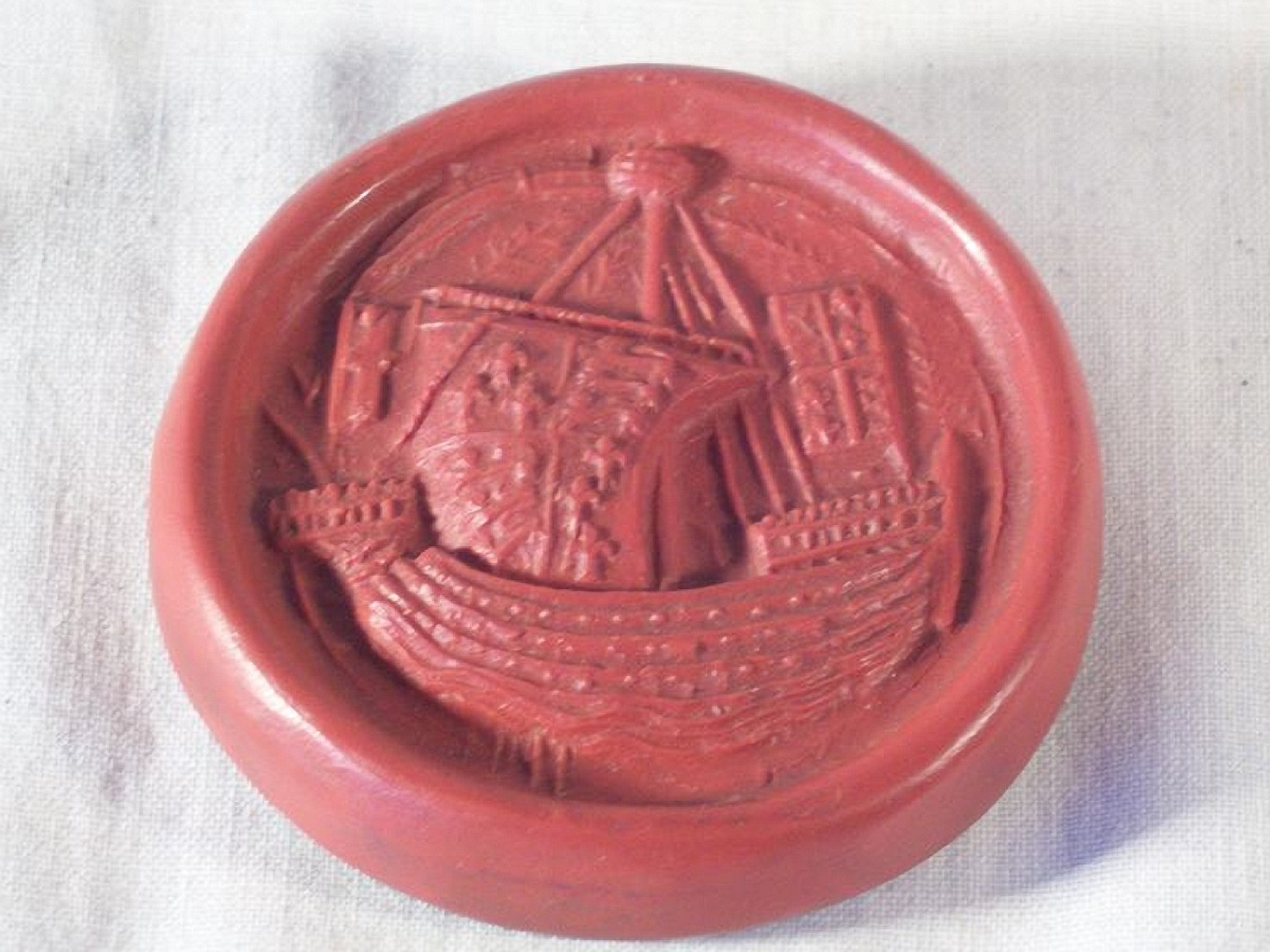
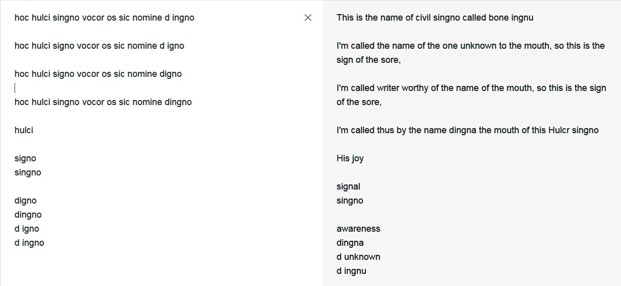
Found something, seems well researched. https://www.british-history.ac.uk/vch/sussex/vol6/pt1/pp164-166 Borough Seal Of New Shoreham (½) The matrices of the seal used by the borough in the early 14th century (fn. 72) are round, 2¾ in. in diameter, and made of latten. (fn. 73) On the obverse are the arms of de Braose, a lion rampant facing sinister (allegedly through the engraver's carelessness) (fn. 74) on a field of cross-crosslets, impaling the three leopards of England; legend, Lombardic, s(igillum) communitatis burgde de nova shoram brewes. On the reverse is the representation of a ship with human heads and cross-crosslets; legend, Lombardic, hoc hulci singno vocor os sic nomine dingno, which alludes to the name Hulksmouth used of the river or harbour in the 14th and 15th centuries and is best translated 'By this sign I am called hulk's mouth, and a worthy name it is'. The ship is said to be of the time of Edward III, (fn. 75) but the last word of the legend on the obverse suggests a date before 1324 when William de Braose surrendered his life-estate in the honor of Bramber, including New Shoreham. The lion rampant facing sinister on a field of cross-crosslets was used on its seal by the urban district council from 1894. (fn. 76)
- 186 replies
-
- 2
-
-
- keelless
- reverse clinker
- (and 4 more)
-
I was going to say that a reasonable interpretation was "This is the symbol (sign) of Hulkesmouth". But I decided to check if the Adur (the river through Shoreham) was ever called the 'Hulk'. Nope, nothing solid, not even firm. I did come up with "In 1457 the port of Shoreham is named in a document as Hulkesmouth alias Shorham. The New Shoreham Borough Seal of c. AD 1295 shows a ship in a curved form." http://www.glaucus.org.uk/Toponymy.htm That suggests the seal is almost 200 years older than the only reference to Hulkesmouth! It also leaves it open that 'hulci' might refer to the ship.
- 186 replies
-
- 2
-
-
- keelless
- reverse clinker
- (and 4 more)
-
Well, I think I've been running around in circles chasing others who are running around in circles chasing their tails. Many seem to be jumping to conclusions and using those conclusions to 'prove' other conclusions. What I haven't seen is any hard facts. Anybody know Latin? The Texas A&M University in 'an introduction to Nautical Archaeology' https://nautarch.tamu.edu/class/316/hulk/ gives hoc hulci signo vocor os sic nomine digno (by this picture of a hulk I am called mouth thus by a worthy name) for the text on the New Shoreham seal. Google translate gives:
- 186 replies
-
- 2
-
-
- keelless
- reverse clinker
- (and 4 more)