


iMustBeCrazy
-
Posts
976 -
Joined
-
Last visited
Content Type
Profiles
Forums
Gallery
Events
Everything posted by iMustBeCrazy
-
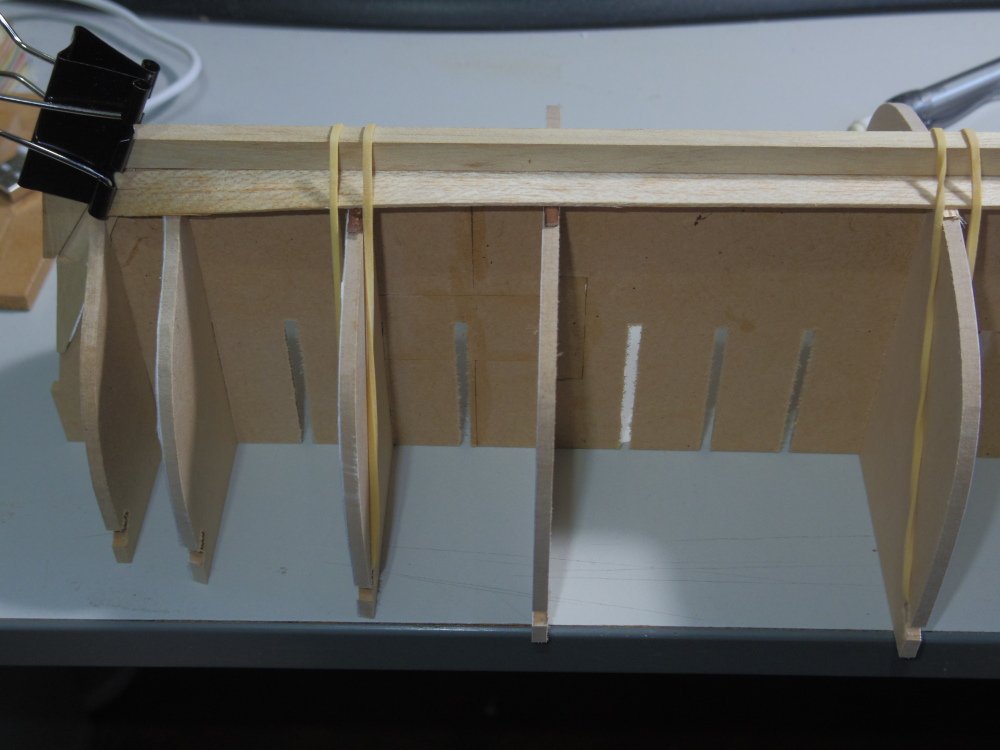
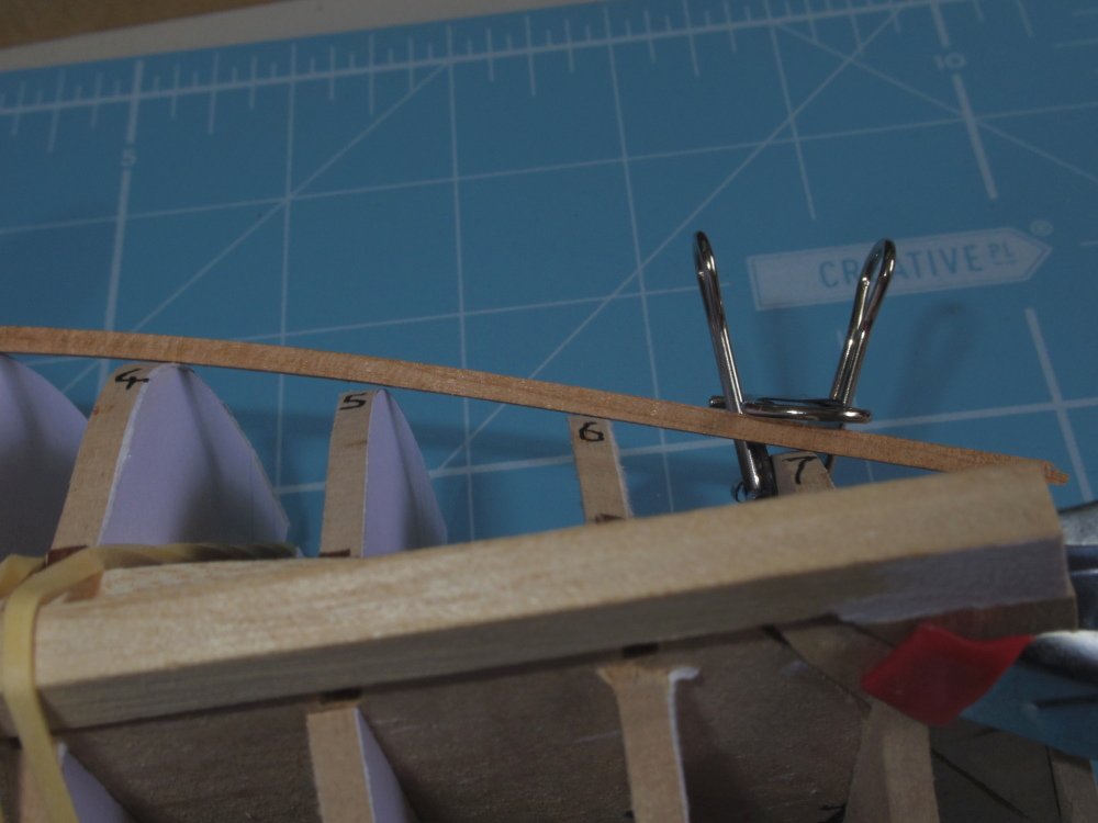
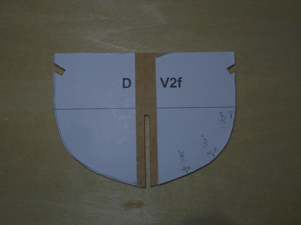
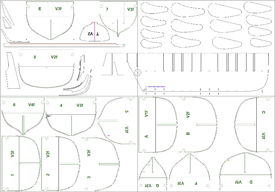
 Welcome all to my - First build log, first scratch build and first clinker/lapstrake build. It's a little scary. Ok, a 16ft cutter based on ZAZ7027 in 1:16 as a stable mate to the Model Shipways Bounty's Launch. This drawing has problems......... Trying to overcome those problems in CAD was beyond me so construction/trial and error was the next choice. Construction is similar to Bounty's Launch, ribs over a jig of a false keel and moulds. First I drew up and made the false keel then I drew up and made the moulds as per ZAZ7027 with the odd numbered drawn as halfway between those shown in the drawing. These were assembled with a friction fit and initial fairing began. This was done with a thin batten (1x2mm) as is traditional, errors were guestimated, corrected in CAD and a new mould was made (actually over 20 new moulds so far). I also drew and cut the keel, stem and sternpost. I did a trial fit of a garboard plank and realised it would be easier for the planking trials if I incorporated the ribs in the moulds, so a new set of moulds was made (that's about 50 moulds total now). Fairing continues but I'm taking a break and starting this log. I have incorporated a few things to make building easier such as the knotches for rubber bands for clamping, does anyone have any other suggestions?
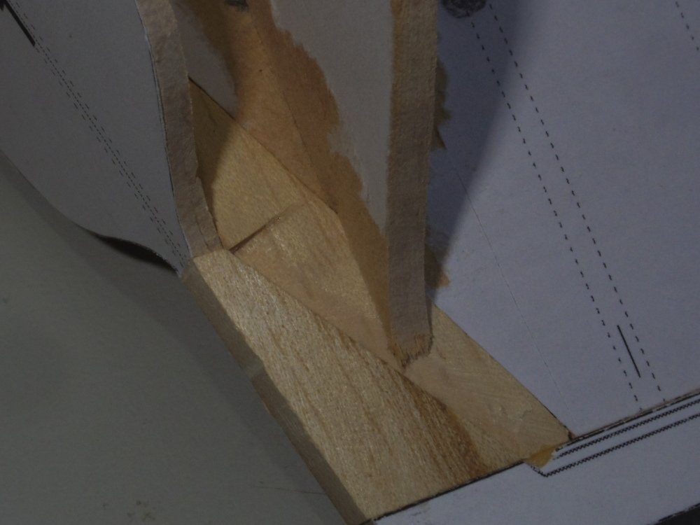
-
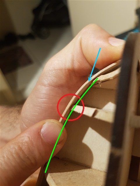
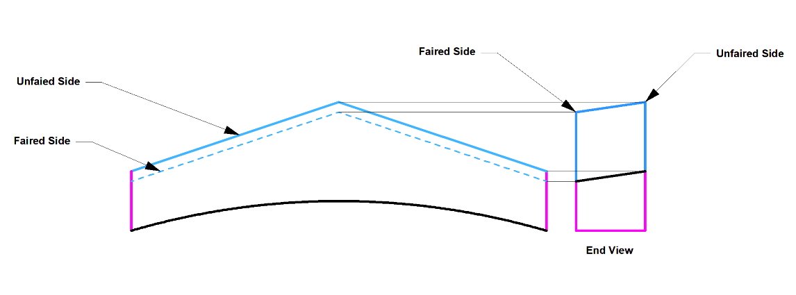
G'day Mango, Probably. First I suggest you watch videos 24, 25, 78 and 85 at https://sampsonboat.co.uk/ They will give you some idea about fairing, setting out and planking. They are not tutorials but you do get explanations. Edge bending is about shrinking one edge of your piece of timber (you can't stretch it). In the picture the green line is a shorter distance than the distance along the adjoining strake so you need to shrink the the edge indicated (blue arrow), that is it needs to be on the inside of your bend.
-
48th Scale imperial rulers. Where?
iMustBeCrazy replied to John Murray's topic in Modeling tools and Workshop Equipment
The Excel 55777 fits the bill but for most of it's length it's resolution is 3 inches. That one seems to be Metric only, the only one I can be sure of is the Tankraft Imperial Pro Modeler Scale Ruler. @John Murray -
48th Scale imperial rulers. Where?
iMustBeCrazy replied to John Murray's topic in Modeling tools and Workshop Equipment
G'day John, best I can offer is that I posted a PDF with some scale rules I worked up in CAD. It prints to scale on my laser printer but you may have to make some adjustments when printing. After printing I just put Scotch Magic tape each side then trim to size. LINK -
I painted mainly because the strakes in the kit were in two very different colours and I just didn't like it. And yes the paint does bring out the imperfections, I may go back and make a curved sanding block that fits between the ribs and polish it up a bit. I do like a 'factory fresh' look so I might paint again. Next time I might play with pre-finishing the inside of the strakes, perhaps with diluted wood glue (after staining if that is the desired look) so they can still be glued to the ribs/frames. Just a thought.
-
My choice (on my Bounty Launch) was to set the riser and thwarts as per the drawing and raise the footwaling? (floorboards) as you are. As you can see in the pic my first try, which felt right, was too low and I had to add some more. I finished up with about 43cm in the real world.
-
And leaving stuff out because every shipwright knows how it's done....... Oh my aching head.
-
I think you were right the first time although this was a preliminary drawing. ZAZ5672 enlarged:
-
Not just a great photo, that's a heck of a lot of work you've done there. Best I can give is 'maybe'. Oak posts at 2 1/2 or 3 inches square would be strong enough but a strong enough mounting at the base may present a problem. I'm not sure.
-
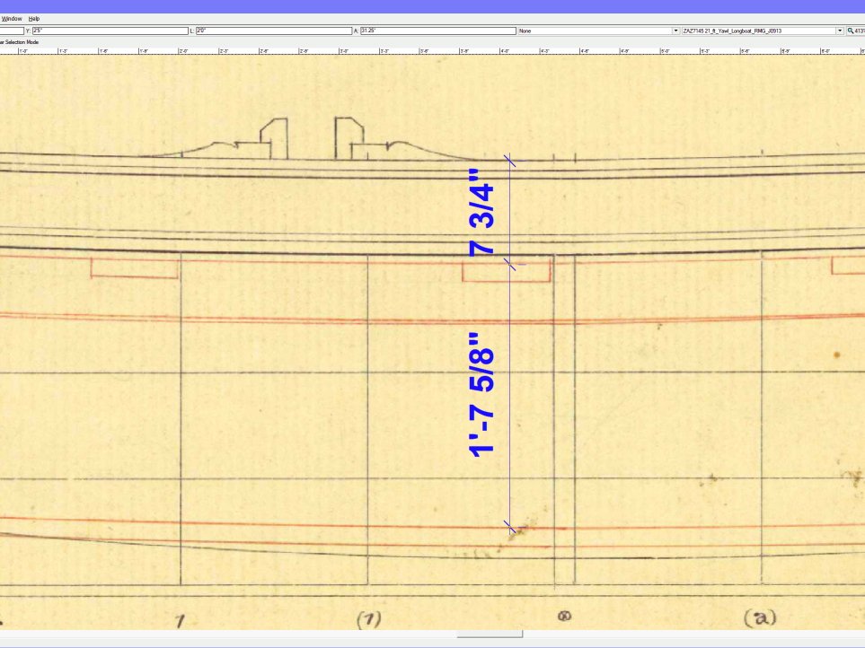
50cm (19.7") would be too tall for me, I think 44 would be the max and I'm 5'10". The drawing you're working from, ZAZ7145, gives 50cm as you suggest but ZAZ7128 (a 26 ft Yawl) gives a much more reasonable 42cm. Many of the boat drawings seem to be based on very tall people Large copies of the above drawings are available from wiki commons: ZAZ7145 ZAZ7128

-
Generally, go to https://commons.wikimedia.org/wiki/Main_Page and in the search box (top right) type in rmg and the ships name (and year if known) eg: rmg Atalanta (1775) That should give you https://commons.wikimedia.org/w/index.php?search=rmg+Atalanta+(1775)&title=Special:MediaSearch&go=Go&type=image I then find it easiest to right click on each image and open in a new tab. In the new tab click on 'Original file' then save the image. Note that only the outboard and inboard profiles are high res. Credit to Allan for finding them.
-
G'day Allan, So if this is 1690 (Thomas Wilshaw fits with that) and we have 23ft boats being fitted with "iron knees" doesn't that open up a new can of worms? How common were iron knees? Does it perhaps mean that the RMG boat drawings not specifically showing wooden knees had iron knees? 'shudder' too much to think about. EDIT, I just looked up Mays Boats of Men of War and the scantlings table ca1800 gives iron knees for Barges, Pinnaces, Yawls and Wherrys. I don't see anything for earlier but the contracts show that it might have been true for a long time.
-
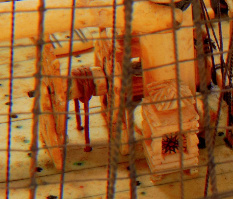
Strangely I have a Dime sitting on my desk, it's a long way from home, before I picked it up I was visualizing a Nickle 😮 What size is the compass, 1/4" square? I must be crazy but you guys are nuts! All of you.
-
Sort of, it indicates that the chock has a beveled face so that when you fair the frame you you don't weaken it too much by making it too thin on that side at the chock. (Hope that makes sense).
-
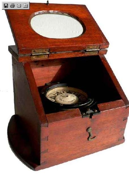
This seems to be a good explanation of an azimuth compass and it's use: wikiwand.com/en/Azimuth_compass
-
Yep, that works, or the helmsman lines up something between the third and fourth shroud etc. Me, I used a gps connected to digital maps. Too easy.
-
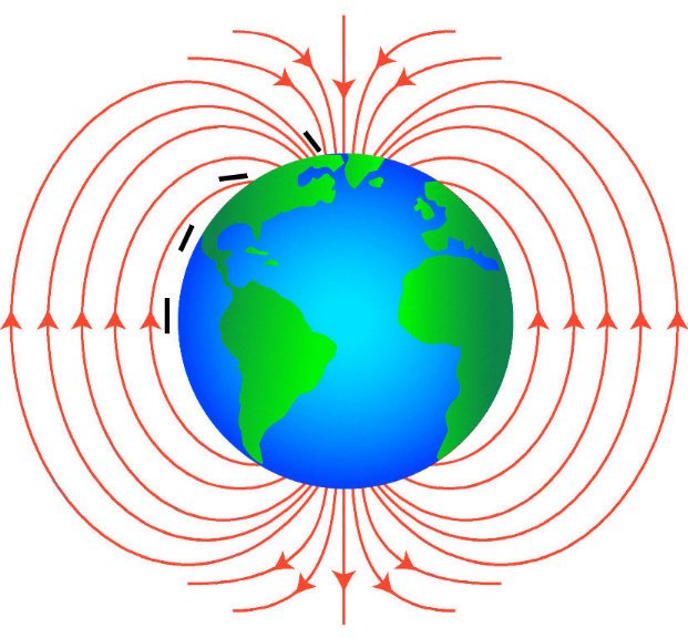
Kieth, think of it this way. It was the helmsman's job to sail the course given and to notify the officer on watch if he no longer could, the officer would then call for the sails to be adjusted or for a change in course (which may require the Captains permission). So the helmsman would use everything he could to maintain a course, the compass, the set of the sails, the wind on his ear, the feel of the wheel, the wake behind him etc. Keith, the azimuth compass was not a magical device for use near the poles, it's primary function was for taking bearings for charting and navigation. It may have been more suitable near the poles than the compass in the binnacle but that would depend on it's design, or the binnacle compasses could have been better depending on their design. One of the problems is that the lines of magnetic flux which are roughly parallel to the earths surface over most of the planet start dipping as you near the poles and the compass needle (or disk) tries to point down to follow them, at the poles the lines of flux are near vertical. So whether a compass works near the poles in part depends on how far the needle can tilt without falling off or jamming. I was thinking more about the safety of you fine model I think the plans were probably followed but I could be wrong.
-
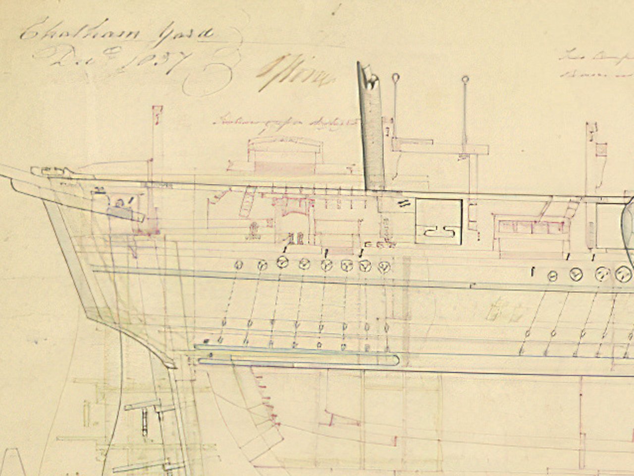
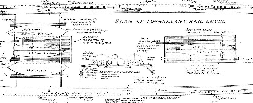
As the compass was probably only in place when in use I don't think I'd bother with a lid and I suspect it had something like a hollow box on the base that fitted over the post. Again just guesses. With the bridge, all the drawings show it extending about 8'8" outside the bulwarks (say 35mm) but I might reduce that to 6' (25mm) if I made this model. But I don't think I could work at this scale.
-
It certainly should be narrower than the skylight. I've re-scaled my drawing and the table is drawn as about* 4'0" x 3'8" which scales down to 0.64" x 0.58" or 16.25mm x 14.9mm with the compass post 6" x 6" ( 0.08" x 0.08" or 2mm x 2mm ). The bridge is about* 1'11" ( 0.3" or 7.8mm ) Post height from the deck is about* 6'10" ( 4'9" above the table ) scaled 1.10" or 27.8mm * variations in line thickness, hand made rulers, paper distortion etc.
-
Oops, you distracted me. I didn't really find anything: I did find a later photo showing the deckhouse roof between the boats but by then it was fitted with a winch and a bloody great (I think iron) water tank.
-
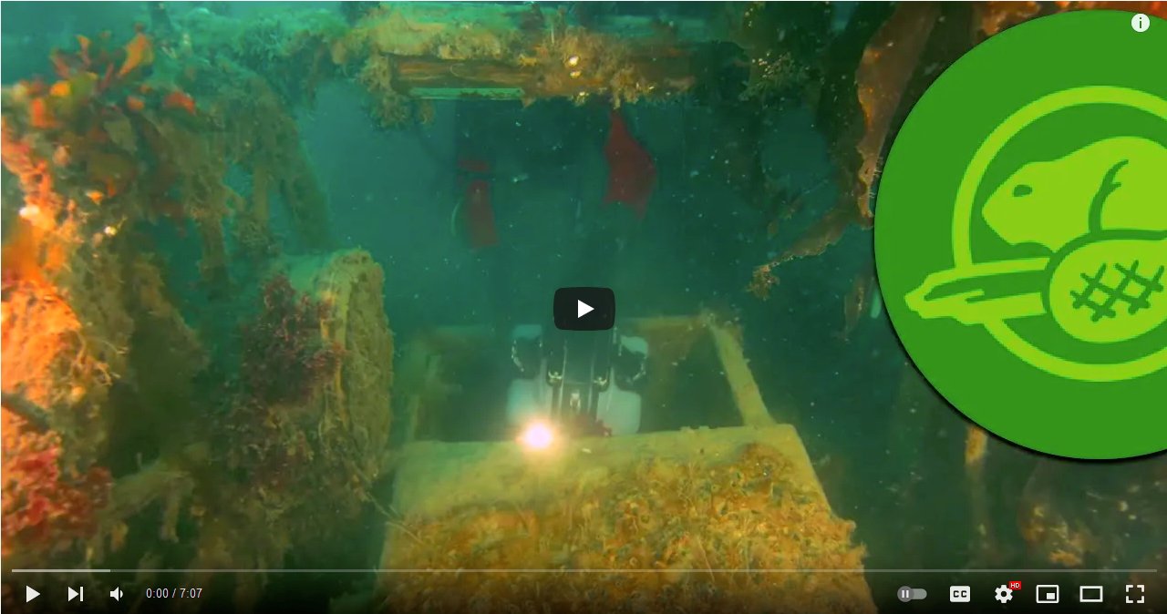
What a pity this scene doesn't appear in the Parks Canada video :( In the Terror site sketch ( post #509 ) we see both skylights have a section of their roof missing, possibly blown out by air pressure as she sank.
-
Are you trying to steal my thunder? You're not supposed to agree with me straight off the bat. I wanted arguments as to why I was wrong. What did they look like? I'm guessing fairly simple as they were removable. Some choices: https://www.rmg.co.uk/collections/objects/search/binnacle?images=yes&date_from=1800&date_to=1848
_Erebus_(1826)_RMG_J1409c2.png.38bc82c405b2ab6089a6cbf67ceadfe5.png)
-
Thanks Keith, I'm sure it's right but it's easy to be sure about your own ideas, even when they're wrong On to the binnacles, this is harder as there appears to be no hard evidence. So, one question at a time. Why wouldn't the binnacles be if front of the helmsman where they belong? Can anybody suggest a reason this is not possible? (that's one question rephrased) Answers must include a stamped self addressed envelope.
-
Why do you think I chose my username? The following is not intended to be condescending in any way, it's just me trying to put into words what I see. My logic. First, the azimuth compass is used to take bearings of objects (hills for example), you need to get your eye right up against the sights (somebody used the right word above but I can't find it) so the compass should be at about eye level. You also need to be able to take bearings in any direction, even behind you. That rules out taking bearings from the bridge. Now lets look at the drawings: The height of the' table' is about two foot three inches, so to take bearings using a compass on the 'table' would mean getting down on your knees also the 'table' is below the height of the bulwarks so you couldn't see anything anyway. The top of the post is about seven foot five inches above the deck which rules out standing on the deck and using a compass on the top of the post. From the top of the 'table' to the top of the post is about five foot one inch which would allow you to stand on the 'table' and take bearings with a compass on the top of the post which is how I assume it was used. You could have a post either side of the 'table' and move the compass from one to the other (or have two compasses) but I can't think of a good reason for that. Also the drawing clearly depicts a square something in the middle of the 'table'. And from Starling 1829:
_Erebus_(1826)_RMG_J1407post1.png.2aa6537425c8591ca72b35a6d8f5cfd1.png)
_Erebus_(1826)_RMG_J1409post2.png.2c9bccfa35545f2eb28fa5243c0aec7f.png)
_RMG_J0519post1.png.3129c9c3057b464a95af4b9fa99ca151.png)
_RMG_J0519post2.png.01bb9748a81bd675a9570c69087c691c.png)


