iMustBeCrazy
-
Posts
976 -
Joined
-
Last visited
Content Type
Profiles
Forums
Gallery
Events
Everything posted by iMustBeCrazy
-
Lightbulb moment. As far out as can still be reached from the deck.
-
I agree, flag halyard. On the Harriet, tied off at the boom as in your Gunboat and in use. However, the flag would have to come down and go back up each time you tacked. On the Gunboat, if they took it to above the mainsheet that could be avoided.
-
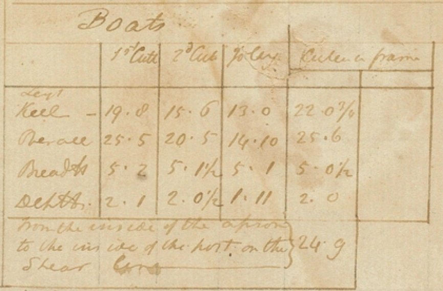
 Yeah, just skimmed 'Narrative of a Survey Volume 1'. He mostly just refers to 'the boat', sometimes 'the whale boat' or 'the jolly-boat' and once 'the small whale boat' (which implies two sizes). When he refers to 'the cutter' he is talking about the Mermaid. One of the boats was lost while being towed and a new one built from the spare frames. I doubt it, on length alone the three big boats could be Launches, Cutters, Yawls, Gigs, Life boats or Wherries but a breadth of around 5 feet would rule out all of those except Wherries. And King's sketches seem to be double ended. Given King's remarks, go with Whale boats. Who does?
 -
I assume you mean me, I've been called a lot of names before but that's a first Not they, that was written by the man himself. It seems that boat naming conventions can be a bit loose. He gives 1st cutter, 2nd cutter, Jolly (or is it Joley) and cutter in frames. So you have to build four then take one apart.
-
Ok, this should nail it down for you: From http://digital.sl.nsw.gov.au/delivery/DeliveryManagerServlet?dps_pid=FL1032664&embedded=true&toolbar=false
-
Relative size:

-
Chris, what I think is mostly guesses, same as everybody else. Based on the painting, I wouldn't go over 12' for the Jolly boat and I wouldn't be surprised if it was actually 10' but in CAD I get about 10' 10". Cradle of some sorts certainly but perhaps wedges. Those boats must have been securely lashed down. Hard to do on a flat surface without crushing them. The last drawing is supposedly to scale, measuring the whaleboat in CAD I get 20' 6" but there must be a margin for error.
-
G'day Chris, Working from what's available: Jolly boat on davits. Boat in water approx 11 feet. Whaleboat location and length (approx 20' 6") Scales are a bit wishy washy so your 20' whaleboats should be fine.
-
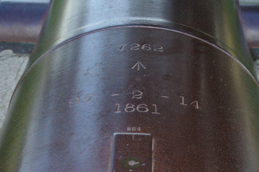
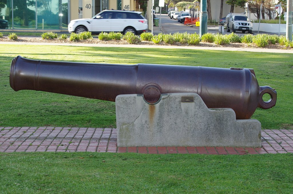
I tracked down the Brighton gun, at Brighton Beach Gardens near the end of South Rd. So, where are the other 15? Perhaps used as moorings at Williamstown.
-
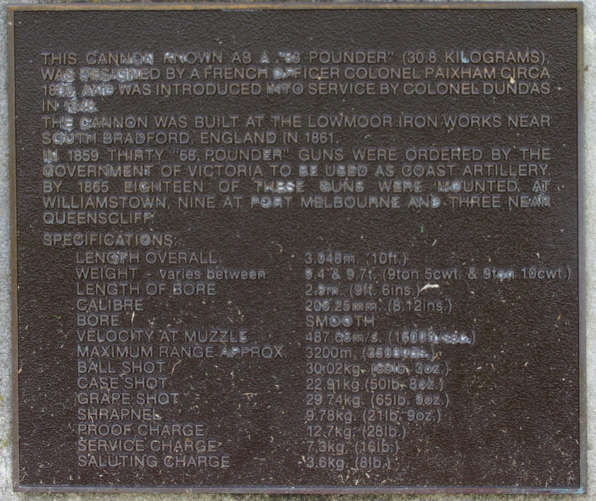
More info: Perhaps 15 to 29 of these around! http://www.cerberus.com.au/reenactors/68_pounder_slideshow.html gives: Ballarat 4 (Eureka Park) 10280, 10284, 10334, 10481 (from another site, perhaps more at View Point, Lake Wendouree attributed to the Nelson but....) Bonegilla 1 10350 Brighton 1 10504 Daylesford 1 10491 Drysdale 1 10276 Moonee Ponds 2 10496, 10498 Port Fairy 2 10502, 10509 7261, 7271 (numbers off barrel not trunnion?) Portland 2 10339, 10302 Warrnambool 1 10310 7045 (number off barrel not trunnion?) This site https://victoriancollections.net.au/items/55b77c242162f119c85679d4 gives "There are only seven 32 Pounder SB made by Carron and fifteen 68 Pounder SB made at Low Moor known to exist in the State of Victoria" with (Reference; Victorian Guns and Cannons, South Western Victoria Assessment, May 2008, item W/B/01; Flagstaff Hill Maritime Village datasheets and archives). But I can't find that document.
-
Looks like there's a few around, 2 at Port Fairy, 2 at Portland, 1 at Warrnambool, 1 at Moonee Ponds plus yours. I noted there was a recommendation to purchase 19 so there might be some more somewhere. This one is at Port Fairy, I took it back in 2015: This is a link to the Moonee Ponds one: https://commons.wikimedia.org/wiki/File:Cannon_located_at_Queens_Park_at_Moonee_Ponds.jpg EDIT, looks like there are two in Moonee Ponds (Queens Park) 10496 and 10498.
-
Some info: http://home.iprimus.com.au/artillerist/news.html
-
Hank, compare these two. Their cheapest portable with their second cheapest (by $6.00) wall unit. https://www.edgestar.com/koldfront-portable-air-conditioners/PAC802W.html https://www.edgestar.com/koldfront-through-wall-air-conditioners/WTC8001W.html Although they are both 8000 BTU of cooling the portable only claims to cool 150 square feet whereas the wall unit claims 350. The wall unit also heats, the portable doesn't. The portable also uses slightly more power to cool less than 1/2 the area. Hope this helps.
-
From best to worst, Split system Box (wall mount) Dual hose portable (if you can get one, they stopped selling them here) Single hose portable A single hose portable sucks outside air in at the same rate it spits hot air out the hose, if the air outside is hot then the only cooling will be directly in front of the unit, the rest of the shed will be close to outside air temp. A dual hose sucks outdoor in one hose, heats it up and spits it out the other. Generally the best budget buy will be a Box A/C if you have the wall space.
-
Lapwing 1816 Revenue Cutter
iMustBeCrazy replied to iMustBeCrazy's topic in CAD and 3D Modelling/Drafting Plans with Software
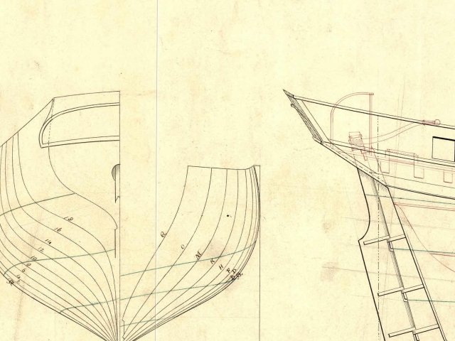
A bit to digest there, the headache doesn't help. (real headache, not caused by you). Using CAD I'm able to use segments of the sheer plan stations, draw in the head and heel, offset a copy by the moulding at the heel and rotate the head to the moulding at the head, compose (join) the four lines in to an object (futtock etc) and so draw each timber in each bend retaining the curves. I'll probably stick to this method. 39 vertical bends and 23 cant frames plus a couple of extra little bits. The other bit is I want these to be drawings of how to build the ship, so each bend and each cant frame has to be drawn anyway. Perhaps you begin to see why I chose my user name. -
Lapwing 1816 Revenue Cutter
iMustBeCrazy replied to iMustBeCrazy's topic in CAD and 3D Modelling/Drafting Plans with Software
No need to groan, I'm only doing a rough PoB so I can figure out the stern. Probably only do the aft third and only plank one side above the wale. But while I'm doing that I might as well draw the extra bulkheads. I will continue trying to draw all bends and the cant frames for PoF plus bulkheads for PoB. As this is largely a family history project, showing the crew accommodation is important, and PoB doesn't do that. -
Lapwing 1816 Revenue Cutter
iMustBeCrazy replied to iMustBeCrazy's topic in CAD and 3D Modelling/Drafting Plans with Software
Well, after chasing my tail around and around and around (that curve at the wale shown in post 52 can't exist) I think I'm going to have to build the stern in PoB to see what's happening. I know the outer counter timber is a straight piece of wood with a kink in it, probably leaning over towards the centreline so that the 'elbow' sticks out a bit but in 2D it's not easy to visualise and harder to draw. No wonder they didn't do detailed drawings. Anyway, comments, suggestions please, I haven't done this before. This will be a fairly rough mock-up for my needs, but I still want the drawings to be useful to others. Starting with the keel, bulkheads/moulds when I have done them.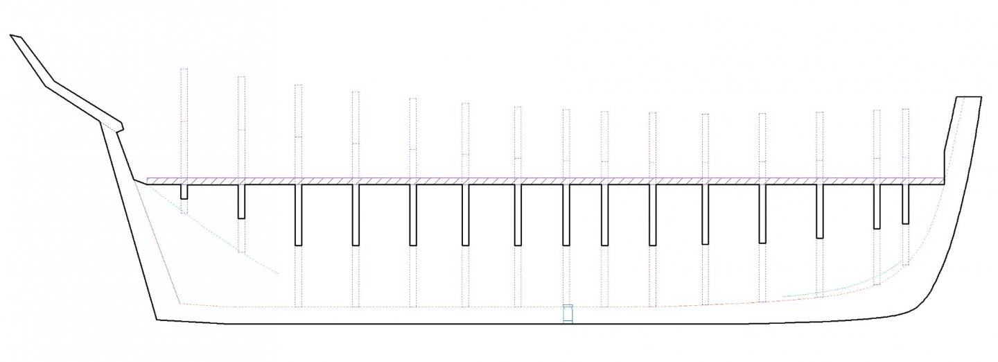
-
Lapwing 1816 Revenue Cutter
iMustBeCrazy replied to iMustBeCrazy's topic in CAD and 3D Modelling/Drafting Plans with Software
Thanks Tony. I think it was brunch. The same bird once caught and devoured a whole rabbit! Admittedly it was a small rabbit but still several times the size of a mouse. Afterwards it could only fly 50 metres between rests. I've been having a break on the drawings as my eyes are going rectangular what with computers, books and TV. Hope to get outside again soon if the weather moderates. Old man winter seems to have arrived early. -
Plan Redrawing Question
iMustBeCrazy replied to Castos's topic in CAD and 3D Modelling/Drafting Plans with Software
I'm still redrawing things, this will continue long past the learning curve. This will be a long job. The sooner others point out errors the less you have to redo. Everything is inter-related, moving one point may mean moving many others. Also when you're happy with something, lock it from editing. You can always unlock it later. -
Plan Redrawing Question
iMustBeCrazy replied to Castos's topic in CAD and 3D Modelling/Drafting Plans with Software
I would say "it depends". If you are trying to duplicate the original then duplicate the original line weights. If you are trying to create a pretty picture then use the line weight that you think looks best. If you are trying to produce a plan to use as templates then choose a narrower line that is still dark enough when printed. But don't get hung up on line weights at the moment, it's better to get them in the right place first, you can change them later. See my Lapwing thread, I'm using all colours and weights so I can more easily see and differentiate the lines. Drawing a thin black line over a thicker black line makes it hard to see what you've done. As I finalise them I'll reduce the number of colours and line weights to suit a nice print. -
Lapwing 1816 Revenue Cutter
iMustBeCrazy replied to iMustBeCrazy's topic in CAD and 3D Modelling/Drafting Plans with Software
First, a small distraction. This morning turned out sunny despite the forecast so I snuck out down to the park for a little exercise and photography. When I got back I modified my balsa mock-up of the stern/counter. It's rough but I think it works.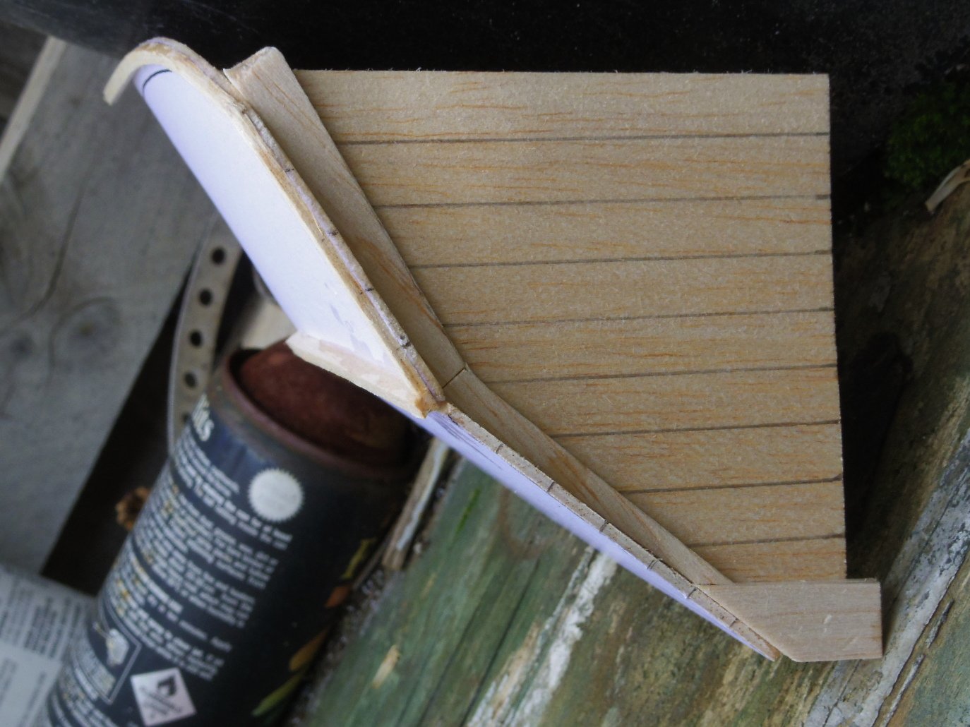

-
Lapwing 1816 Revenue Cutter
iMustBeCrazy replied to iMustBeCrazy's topic in CAD and 3D Modelling/Drafting Plans with Software
Thanks Bob, I saw Fukui's post just after wrote the above. It's a possibility but I'll have to draw it to see how it looks.
-
Lapwing 1816 Revenue Cutter
iMustBeCrazy replied to iMustBeCrazy's topic in CAD and 3D Modelling/Drafting Plans with Software
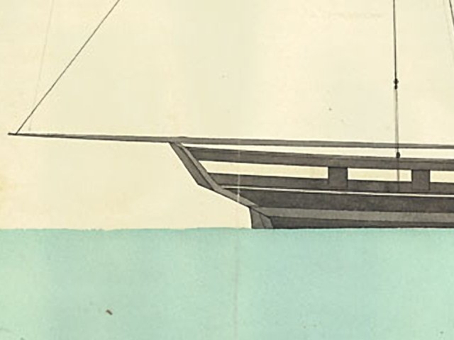
Well, it took two days just to draw the counter timbers and I've just moved one two inches so it now has to be totally redrawn. So I've been trying to understand the yellow area in the drawing below. The 'trim piece' is shown on the sail plan of the Lapwing (Danish archive) and the Nightingale. It probably extends out to the dotted line and maybe more, framing the planking. The stern rail must blend into it somewhere somehow. But the question is, what is the structure, how is it supported? It doesn't seem to overlap the counter timber enough to be fixed to it. Can anyone point me to anything that might help? Or point out anything I may have misinterpreted from the drawing?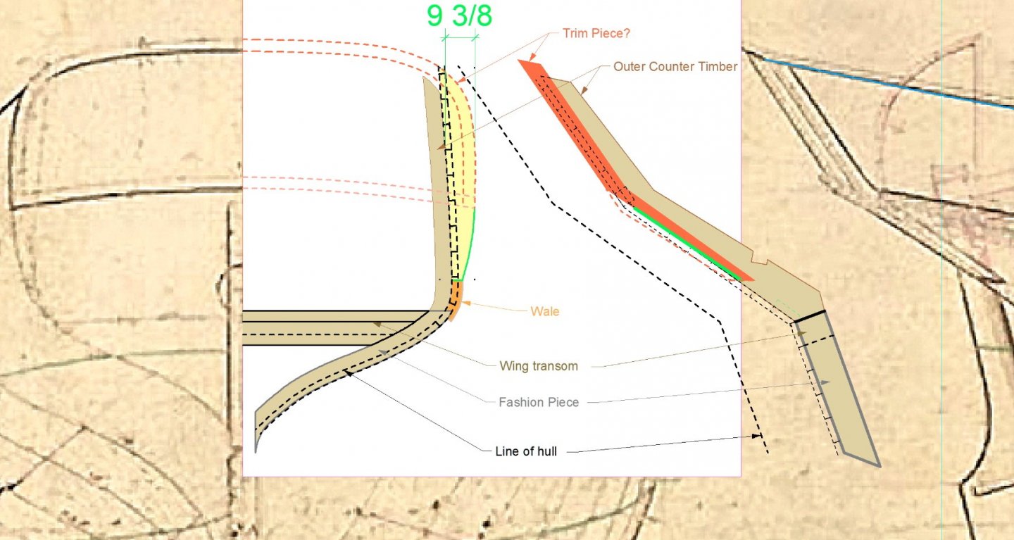
-
These days, factory produced mdf sheets come with four very square corners and four very straight sides. Even the smaller sheets. To make the above shooting board, cut two rectangles from mdf each with 1 square corner and two straight edges (1 long and 1 short) stack and clamp the pieces aligning the long edges with the top piece set down from the top edge of the bottom piece. Fix a fix a stop piece across the top of the bottom piece using the top piece to keep it square. Unclamp. The bottom should now have a stop which is square to it's long edge. Sounds really confusing but actually very easy once you grasp the idea.
-
Lapwing 1816 Revenue Cutter
iMustBeCrazy replied to iMustBeCrazy's topic in CAD and 3D Modelling/Drafting Plans with Software
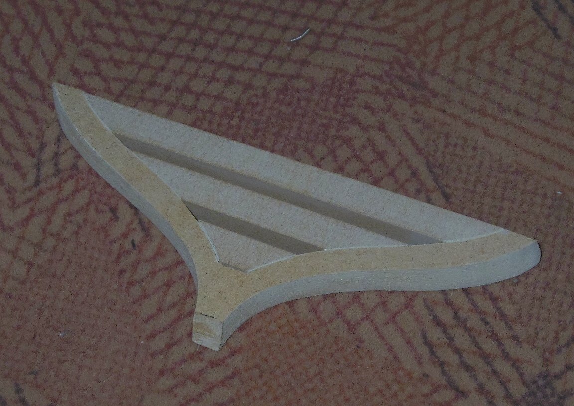
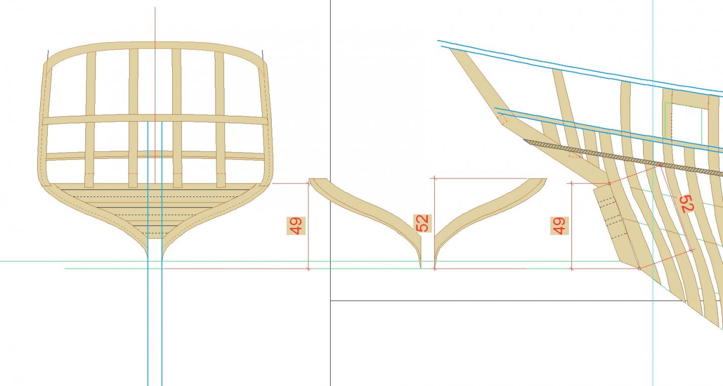
3D Transom (MDF): Note that when making any part from the drawings you must make sure that the part is drawn 'square on', those that aren't such as the transom, counter, cant frames etc. need to be corrected. For example the transom viewed from the stern appears to be 49 inches high but as shown is is actually 52 inches. To correct this, the drawing from the stern needs to be stretched vertically by 52/49ths (1.0612244). Also you need to allow for any bevelling which may not be shown. In this case, the fashion pieces are wider on the forward side and the bevel is shown on the corrected drawing. Yes, I forgot the bevel the first time.