


dunnock
-
Posts
529 -
Joined
-
Last visited
Content Type
Profiles
Forums
Gallery
Events
Everything posted by dunnock
-
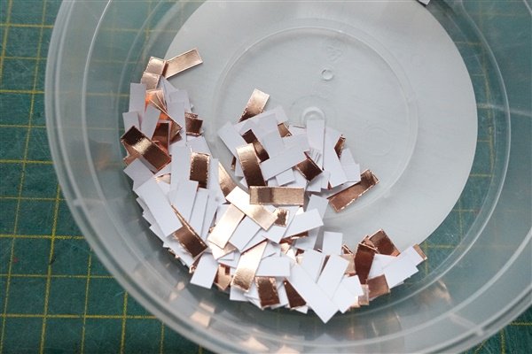
I drew the waterline using a Model Shipways marker that I recently bought to replace my home-made Heath-Robinson affair. I was better off with my own version. I found The Model Shipways marker very difficult to set up. It’s difficult to tighten the pencil holder firmly and it has a tendency to move as you draw around the bow and stern. I don’t think that I’ll be using it again. Having marked the position of the waterline in pencil, I used Tamiya tape to provide a clear line and fixed a batten using 1x1mm boxwood strip along the the topside of the tape. I used super glue gel at the bow and stern and pva midships where there is a straighter run. I’ve cut a good few plates from the supplied copper tape but will probably need more if I compare my pile to the size of the one shown in the manual. The recommended cutter from RP Toolz is out of stock at the few sellers in the UK. Most of the other cutters available all looked a bit cheap and cheerful but I found a similar cutter for around £50. It's well built and does the job. The first two rows are laid on the port side. It’s quite fiddly peeling off the backing paper and lining up the thin foil. Slow work but after a couple of rows, I’m getting into a bit more of a rhythm. David
- 114 replies
-
- 10
-

-
- Vanguard Models
- Speedy
- (and 1 more)
-
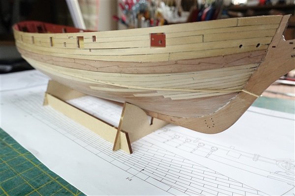
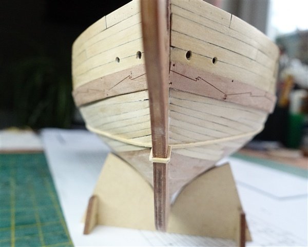
Thanks everyone for the likes, comments and general encouragement. It’s much appreciated. I did a little bit more work on the waterway, reducing the height and improving the angle to the deck. Before I could fit the inner bulwark patterns I needed to trim the bottom edge to allow for the waterway. It was painted with Admiralty Paints Red Ochre before glueing in place. I made the spirketting from 3mm walnut strip which is a little undersized but I think looks fine. This was also painted before fitting. There is no provision for scuppers and I can’t see them on the Admiralty plans but I’m sure there would have been three or four per side, there being no other way of draining the deck. I'll look into this a bit more before deciding what to do I moved on to the main wale, which gave me a few problems. When I first trial fitted the kit part, it’s natural line seemed to leave it too high at the stern. When I repositioned it, I realised that an earlier error when I fixed the first strake slightly low was now going to come back to haunt me. This is particularly noticeable on the starboard side although port side too, where I thought I had got it correctly positioned, is also slightly out. I don’t want to cut out all the upper planking so I’m going to have to live with it and hope that it won’t be too obvious when all the rigging is in place. So after some considerable difficulties in getting the wales to conform to the shape of the hull they are finally fitted, with the help of superglue gel and a hot iron. The bow section of each wale has been chamfered on the back to finish as close to flush with the main planking at the stem as possible and I've left them long at the stern to be trimmed when the counter side timbers are added. Thanks for looking in David

- 114 replies
-
- 7
-
-
- Vanguard Models
- Speedy
- (and 1 more)
-
Thanks Ron and Andrew, very kind of you to say so David
- 114 replies
-
- 2
-
-
- Vanguard Models
- Speedy
- (and 1 more)
-
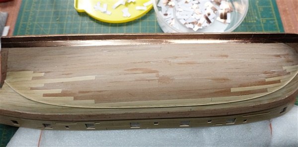
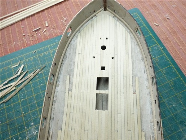
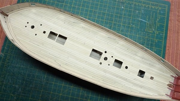
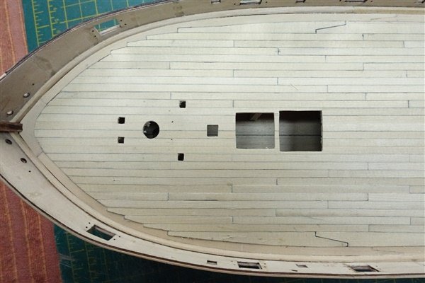
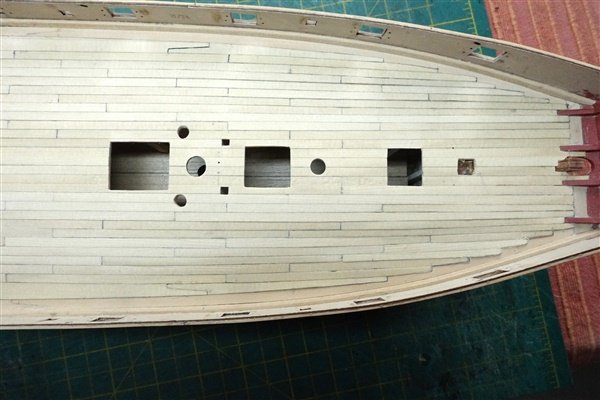
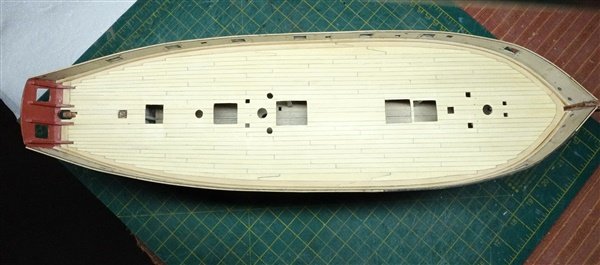
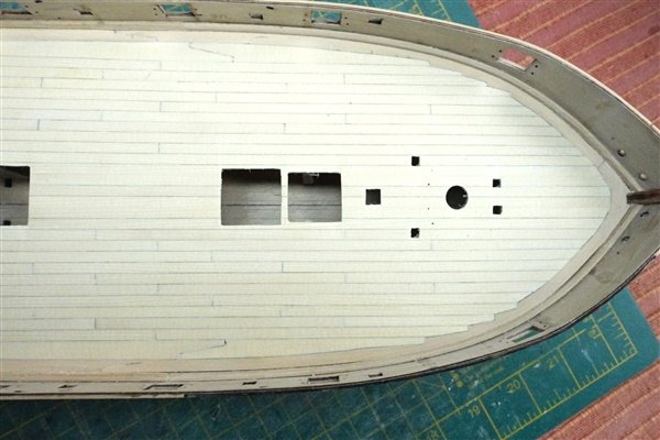
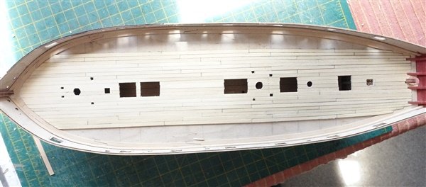
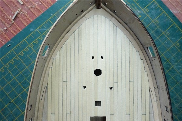
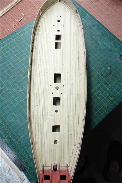
A quick update which takes me to the completion of the deck planking. The forward and mid sections of the margin plank were removed along with the three joggled planks without too much difficulty. And replaced with a new margin plank and deck planks The final plank adjacent the margin plank was wider than I would have liked and once again could have been avoided by drawing a full planking plan. However the overall result I think looks OK. The deck was scraped flat and then sanded with 400 grit before giving it a couple of coats of shellac with a light rub of 600 grit in between. Thanks for looking in David
- 114 replies
-
- 15
-
-
- Vanguard Models
- Speedy
- (and 1 more)
-
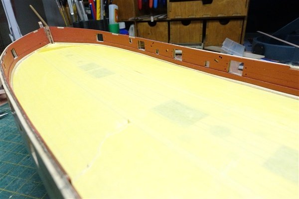
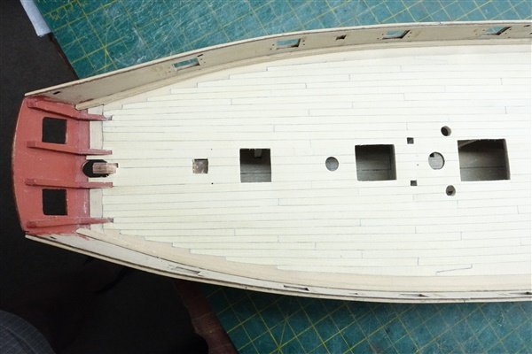
Thanks to all for the likes. Deck planking was generally proceeding well. I hadn’t been planed some of the strips sufficiently which means there’s a fair bit of scraping and sanding to do. Tapering the planks and cutting the joggled ends into the margin plank was working well. I had to redo one two planks that I wasn’t happy with but otherwise I was satisfied. I only saw a potential problem when I was laying strake 13 and I realised that the forward plank of strake 14 was going to cut across the scarph joint of the margin plank. I can’t see a way of fitting this plank without cutting across the scarph and altering the existing joint doesn’t seem possible. I think I only have two options: carry on regardless or do the job properly. The latter means that I have to remove at least the last three planks at the bow, remove the margin planks back to midships and cut a new one. The lesson for me here is that if you are going to modify the standard kit, you’d better look a good few steps ahead to check the consequences of that change. If I had planned out the entire deck planking before starting rather than doing it as I went along, I might have avoided this problem. Where did I put that IPA? David
- 114 replies
-
- 6
-
-
- Vanguard Models
- Speedy
- (and 1 more)
-
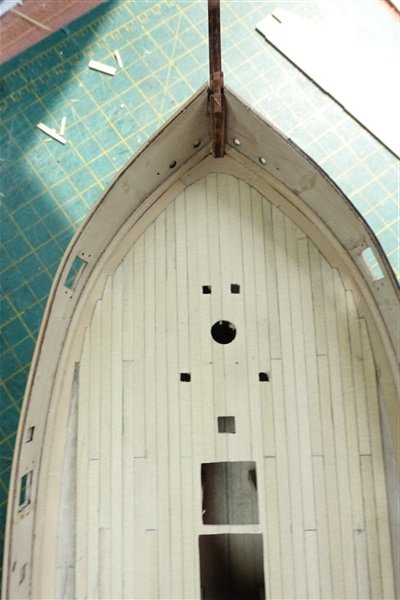
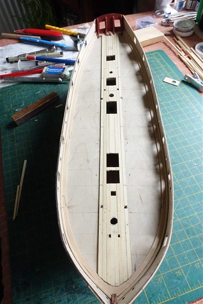
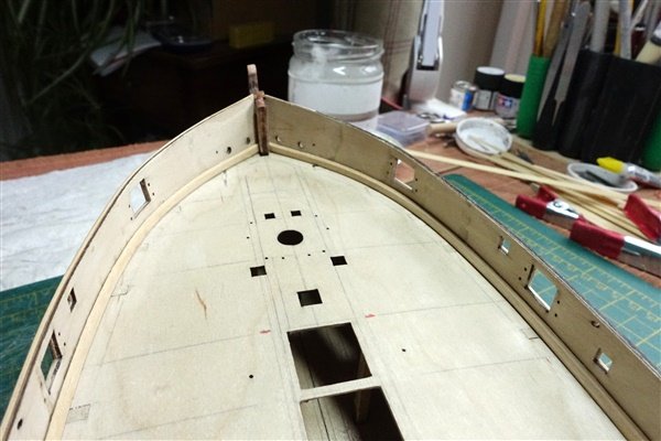
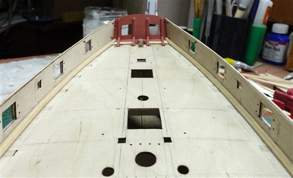
Thanks everyone for the likes. Deck planking has begun with a waterway. This is the first time that I’ve included one in a deck. I looked at several references before staring which showed a variety of patterns: some of equal height and width and others wider on the deck than the height. I started with a length of 3x3 mm boxwood because that was the most suitable that I had around. I marked 1mm down from each edge then chamfered the corner off between the marks with a scraper. The strip was flexible enough to bend round the bulwarks and I did each side in two pieces. I wasn’t sure what sort of joint to use and in the end just butted the two parts together. The margin plank was a bit trickier. I made each side in three sections of 4x1 mm boxwood strip which are scarphed together. The bend at the bow is severe but I was able to edge-bend the planks to fit with three cycles of setting out and drying the plank. Rather than join port and starboard margin planks directly at the stem, I made a deck hook cut from some boxwood sheet. There isn’t one shown on the engraved deck and I don’t know if it’s an accurate representation but I like the look of it. I will joggle the deck planks into the margin as I go. I must have had a senior moment when I placed my order for wood because I received a bundle of 2mm thick strips of AYC (as per the confirmation) instead of 1mm that I should have asked for. I have spent an unhappy couple of hours shaving 1mm from each piece with my plane before I can start planking the deck.🙄 Thanks for looking in David
- 114 replies
-
- 8
-
-
- Vanguard Models
- Speedy
- (and 1 more)
-
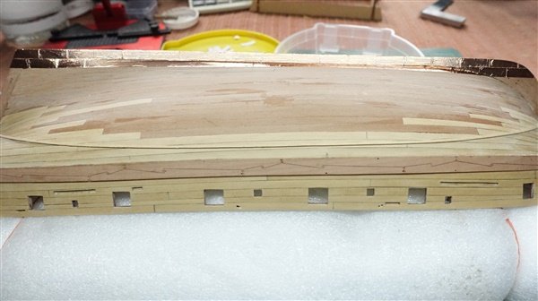
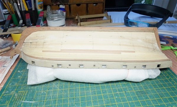
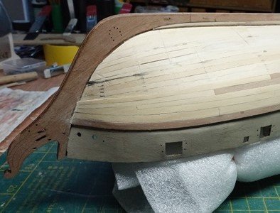
The external planking of the bulwark is completed. Cutting the slots for the channels and drilling for the fixed blocks in the second strake turned out to be easier than I expected despite some of the slots being very close to the edge of the plank. The third strake is only 3mm and would need to be cut down from 4mm so the top strake was fixed next. Again slots were needed for the stools and holes which represent the fixed blocks. Finally the third strake measured, cut and sanded to fit. The gun and sweep ports were roughly cut out as I went along but now they had to be cleaned out with files and sanding sticks made up for the purpose. It took a couple of days to complete this and sand out the surface of the bulwarks. Finally the hull, down to the approximate level of the waterline, has been given a single coat of shellac and rubbed down with 600 grade paper. The shellac brings out the colour of the boxwood and gives it a satin finish. Perhaps not an authentic look but I'm happy with it Thanks for looking in and for all the likes David
- 114 replies
-
- 9
-
-
- Vanguard Models
- Speedy
- (and 1 more)
-
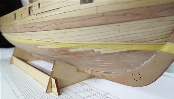
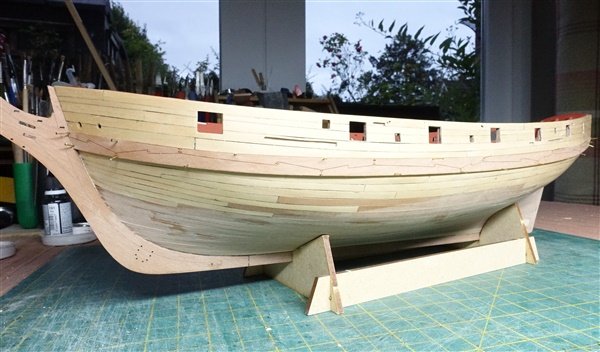
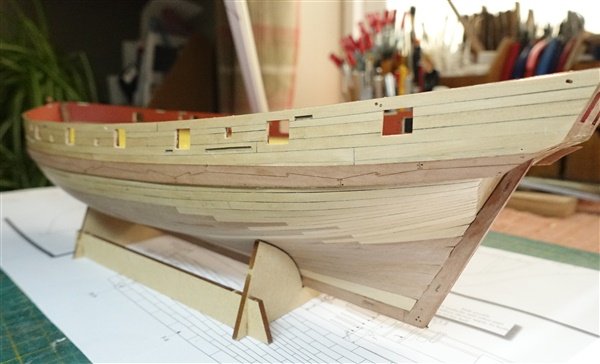
Hull planking below the bulwarks is completed. When the third band was completed, I took another, more critical look at the garboard plank I had installed at the beginning and decided that it wasn’t good enough. I ripped it out and replaced it with another made from strips of my precious 6mm boxwood. Despite best efforts, the difference between the two sides that I mentioned before, persisted through to the final band of planking. A half stealer was added three up from the keel on the starboard side but on the port the stealer was worked in at two above the keel. It also had to be about twice as long as would normally required. Starboard stealer Port side The hull was first scraped and then sanded back to something like smooth. I had to glue some joints between strakes perhaps because I had been too enthusiastic in bevelling the edges and they had become thin after sanding. I used a small amount of filler in the gaps between planks and sanded it off. For the time being I am happy with the result but I’m wondering if to apply a coat of shellac as sealer. I nought to test whether it will have any effect on the adhesion of the copper tape first. I’m now working on the outer bulwarks. I want to continue with boxwood but will use the excellent laser-etched layout as my pattern for the planking plan and positioning of channels, fixed blocks etc. The plank width is a median 4mm but the first strake includes the scribed mark indicating the top of the wale and overall needs to be 6mm. But the first plank in this strake at the bow rises t o 7mm so had to be cut from boxwood sheet. The position of the hawse holes were also marked on this plank. Having fitted this first strake I noticed an error in the position of the first pear wood strake of the hull on the starboard side which is 1mm lower than it should be at the stern. It must have slipped when it was being glued up. I only noticed after the first bulwark strakes were laid and looked at their height against the transom ports. It would be too big a job to remedy now and will eventually be covered by the wale. Even so it’s annoying. The second strake to be laid is a bit more complicated as the slots for the channels need to be cut into it. Thanks for looking in. David
- 114 replies
-
- 8
-
-
- Vanguard Models
- Speedy
- (and 1 more)
-
Great idea Andrew to serve the anchor rings prior to bending and fitting. I always struggled to make a decent fist of it. With a better serving the seizings must go on better too. I'll definitely try your method on Speedy. David
-
Well done. a lovely model that you should be very proud of David
- 562 replies
-
- 3
-
-

-
- vanguard models
- alert
- (and 2 more)
-
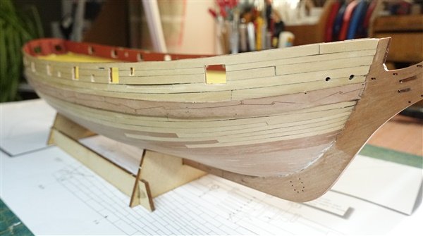
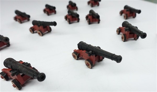
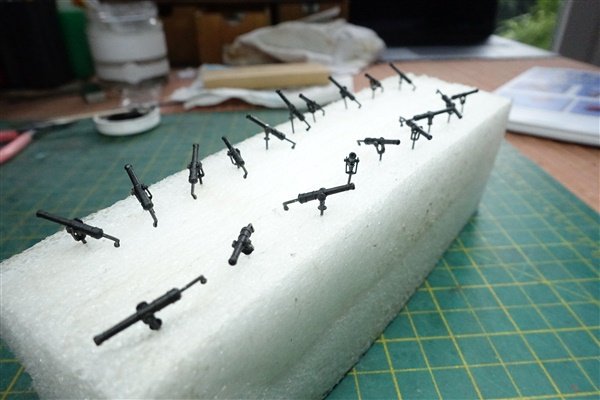
The 14 guns have been assembled. The PE eyebolts provided looked a bit chunky to me and replaced them with 2mm Amati eyebolts. I would like to add the axle pin but there is little room for one in the outer axle so will have to think about how this can be done. When the guns are ready to be added to the ship I will add breeching ropes and will attempt the training tackles but 2mm blocks are required and are going to be very fiddly. In the meantime my wood has arrived from Hobbymill.eu. It’s of excellent quality: very well finished and consistent sizing and colour. The boxwood is paler than the stock I bought from Original Marquetry a while ago so I can’t use them together. I requested some maple for the decking but it was not available so I will be trying out some Alaskan Yellow Cedar when the time comes. The first band of planking is completed using boxwood above the waterline and the kit pearwood below. The planks are tapered and edge-bent for the most part with only a couple that are spiled. For the first time I have used superglue gel to attach the planks as recommended by Chris and found that it works really well. Just a small spot at about 2 -3 cm intervals is enough to firmly attach them. I needed to use a little heat to secure where a severe twist is required at the stern. I looks like there is a slight difference the two sides which I will have to watch as planking proceeds It was perhaps unnecessary as one wasn’t used for the prototype build shown in the manual, but I added a drop-plank at the second strake below the wale because the planking seemed to be getting quite tight at the bow. I’ve remeasured the second band of planking. Only a few more planks of boxwood to add and then it’s pearwood all the way down. Thanks for dropping in David
- 114 replies
-
- 9
-
-
- Vanguard Models
- Speedy
- (and 1 more)
-
Copy away Andrew. If you had been ahead of me in the build I would definitely have taken a lot of your ideas 😁 David
-
That's a fine model you have built and a great log too with much useful detail that I will shamelessly copy. David
- 562 replies
-
- 4
-
-
-
- vanguard models
- alert
- (and 2 more)
-
Thanks Andrew, It's a great book and a bit of a bargain. David
- 114 replies
-
- 1
-
-
- Vanguard Models
- Speedy
- (and 1 more)
-
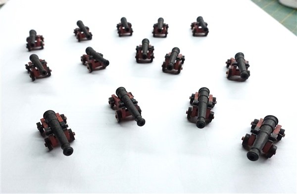
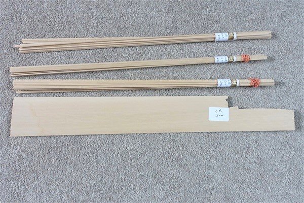
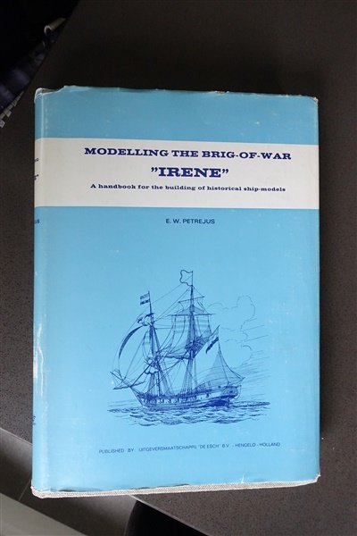
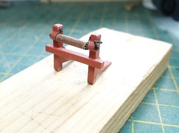
I saw this book ‘The Modelling of the Brig of War Irene' on the Nautiek website which looked interesting and bought it through Abe Books. The book is mainly about ‘Irene’ – an English Cruizer Class brig, HMS Grasshopper built in 1806, captured in 1811 and renamed Irene by the Dutch. Not directly useful as a reference for Speedy but as well as details on Grasshopper/Irene, it contains a wealth of information on fittings and rigging of other classes of ships: British, European and American. I have made up all 20 swivel guns and have put together the components for the guns. There was a fault on the barrels of the 4-pounders but Chris responded to my query immediately and will be sending replacements. The cap squares are part of the carriage sides, so the sequence for construction is slightly different from the norm. The option of a PE brass cap square, which I understand from earlier logs was available, is no longer included. The integrated cap square makes for easier assembly but a steady hand is need to paint them matt black One side and the two axles are glued together first. The barrel will be inserted into the built-in cap squares and the second side glued in place. I made a jig for the first stage to keep things square but will not be possible (or perhaps necessary) to use it to fit the barrel and second side. The PE carriage bolts have been blackened and will be slipped through the holes in the carriage sides when assembled. There are no carriage beds in the kit, the quoins being glued directly to the axle and bed bolt. I thought it would be better to have the quoins on a bed so have made a set from 0.8mm pear fret. I have sanded the quoins into a wedge and will need to adjust the position of the quoin to allow for the extra thickness of the carriage bed. I will have to wait until the deck is planked before I can fix the quoins in position to make sure the barrels will lie centrally within the gun ports. The trucks have been removed from the fret and rounded off without reducing the overall diameter. David
- 114 replies
-
- 6
-
-
- Vanguard Models
- Speedy
- (and 1 more)
-
Thanks for your kind comments mugje and Andrew and to others for their likes David
- 114 replies
-
- 2
-
-
- Vanguard Models
- Speedy
- (and 1 more)
-
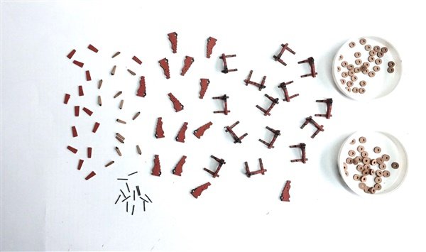
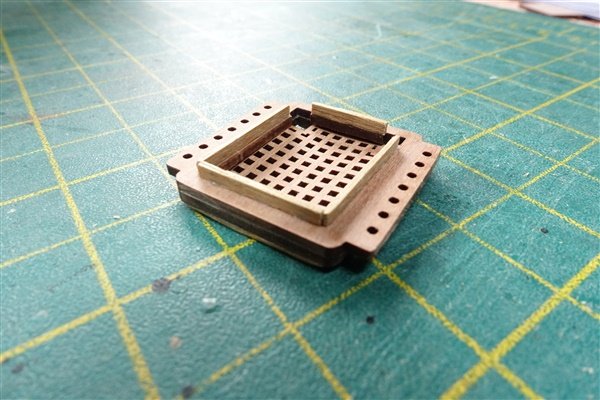
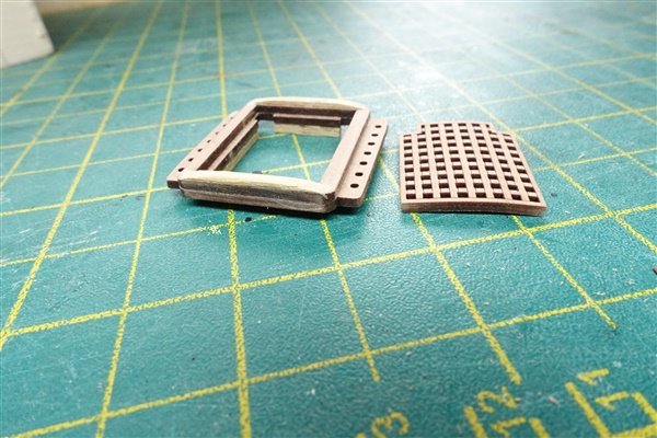
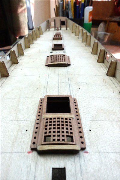
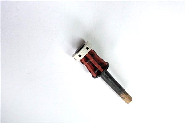
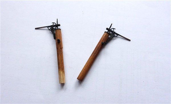
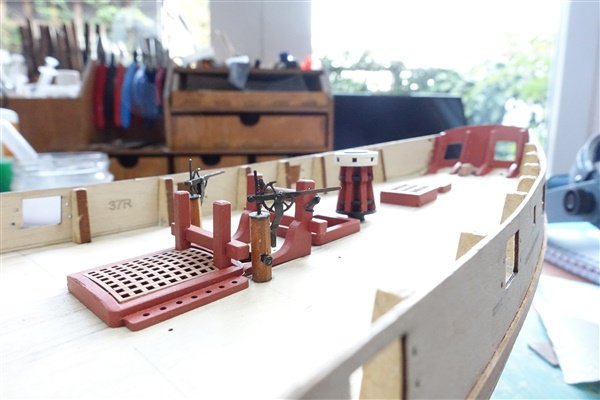
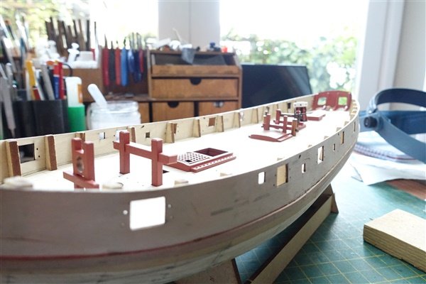
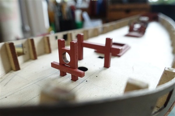
Thanks for the likes everyone. I’ve completed most of the centre line fittings. I added some strips to the ledges of the coamings to give enough depth to sand a curve to the ledges. I also fitted some bits of 2 x 1mm strip to cover the edges of the false deck and give the appearance of deck beams. The companion way hatch cut-outs needed cutting back by 1mm all around to allow for these strips. On the main hatch and the aft companionway hatch, I wasn’t sure whether these too should have a slight curve to their ledges. For the moment I have left them flat. The gratings take a curve quite easily after a short soak and then drying around a suitable former – a jam jar in my case. Inevitably, I broke the very delicate axles on the main mast windlass but it was easy enough to replace them with pins. I decided on a more colourful paint scheme for the capstan – it looks a bit Harlequin-like but I’m happy with it. The deck pumps have been modified. The pump casing was made from some 6mm square limewood filed into an octagonal cross-section and now matches the shape of the pump cap. An outlet has been added made from 2mm styrene tube and fitted to the casing at 90deg to the handle. I have left the flue and it's coaming and the mast bases for now but this is how the completed fittings look after painting The fittings will now be packed away until the deck has been planked and I'm moving on to the swivel guns. David
- 114 replies
-
- 10
-
-

-
- Vanguard Models
- Speedy
- (and 1 more)
-
Thanks very much BE. David
-
Many thanks Andrew, I was sorry to hear about your health problems and the loss of your furry companion but I'm glad to see that you are getting back to shipbuilding. My daughter gives me mate's rates but I'll see if she has mate's mate's rates too! 😀 David
- 152 replies
-
- 1
-

-
- Vanguard Models
- Cutter
- (and 2 more)
-
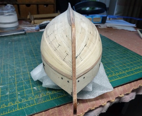
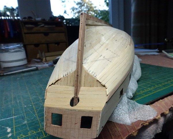
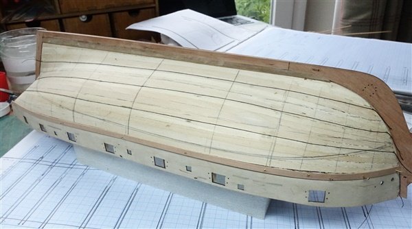
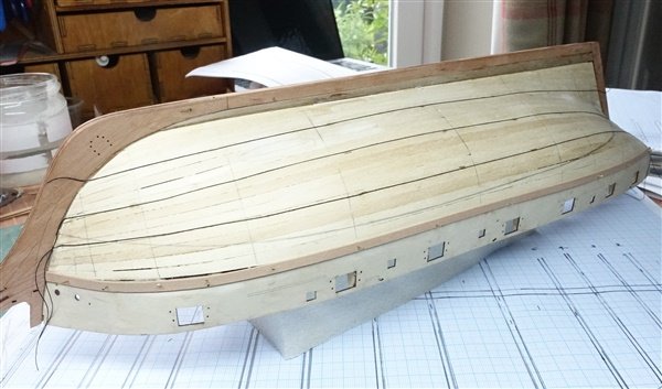
Just a short update... I began with a garboard plank – even though it will be covered in copper eventually. I used some 6mm walnut that I had knocking around. I hope that I have got it about right with not too much of a smiley face at the bow. I used the outer bulwark patterns as a guide to position the first plank, pinned and then glued them in place after removing the bulwark pattern. I have divided the hull into four bands for planking using cotton thread to mark them out. I’m now waiting for supplies of wood which I have on order from Hobbymill.eu. It will be about two weeks until it arrives so in the meantime I’ve started making some of the centre line fittings. Thanks for looking in David
- 114 replies
-
- 7
-
-
- Vanguard Models
- Speedy
- (and 1 more)
-
Hi Rob, I'm just catching up on your log. It's great to see you back modelling again and making a lovely job of Erycina too. David
- 47 replies
-
- 2
-
-
- Erycina
- Vanguard Models
- (and 1 more)
-
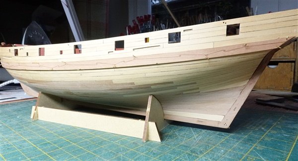
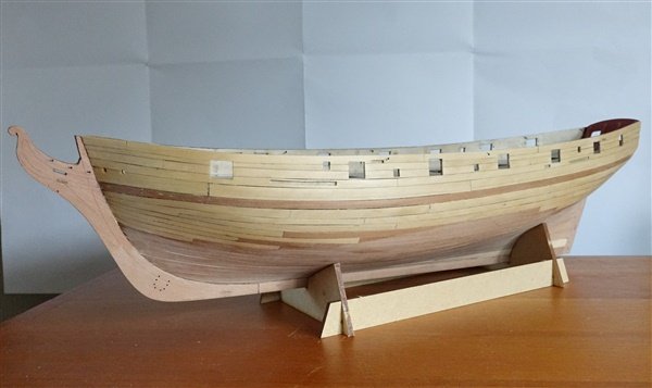
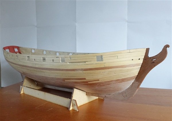
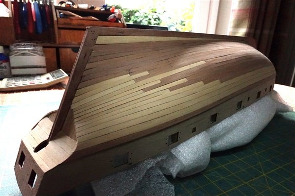
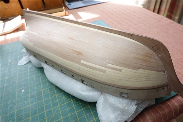
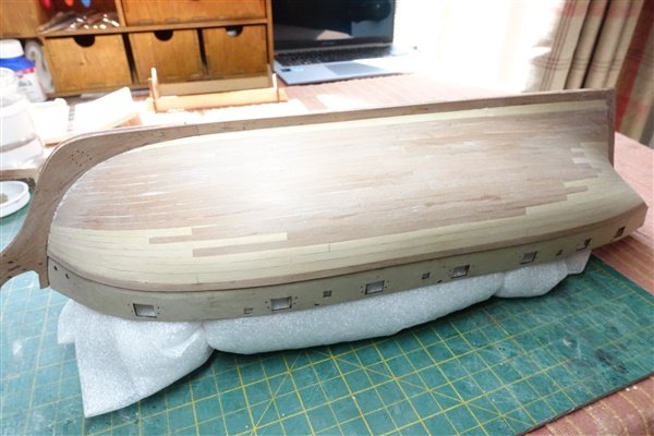
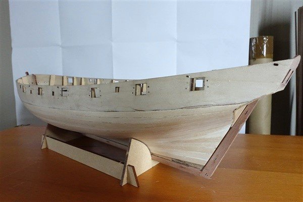
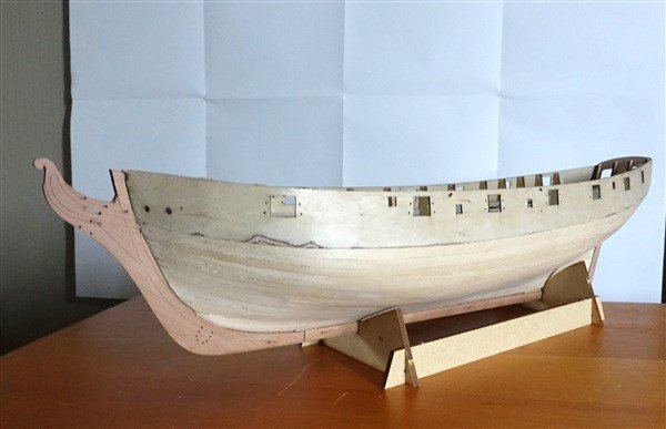
Thanks Lee and to all the others for their likes. Sanding the first layer of planking is done. A little bit of filler was required here and there but otherwise I’m quite happy with the results. The keel and stern post and stem pieces have been added. Getting the locating tabs into the slots was a bit fiddly and make sure that you put the forward part of the keel (part 108} in the right way round… I planked the stern counters using boxwood strip rather than the provided laser-etched kit pieces although they were used as patterns to achieve the required curve on the upper counter piece. There's a bit more preparation to do before I can move on to the second layer of planking, which I will do partially in boxwood and the rest, where it will be covered in copper, in the pear strips supplied. I need to mark the position of the waterline to know where the transition should be. At a later stage I will also probably replace the outer bulwark patterns with boxwood but I need to think what to do about the various slots and holes for channels, stools and fixed blocks in these pieces. David

- 114 replies
-
- 13
-
-
- Vanguard Models
- Speedy
- (and 1 more)
-
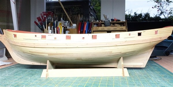
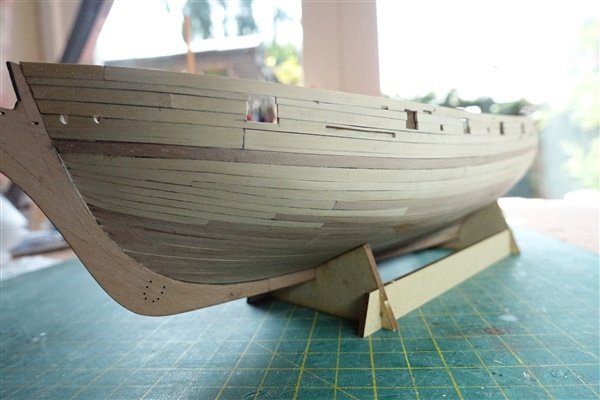
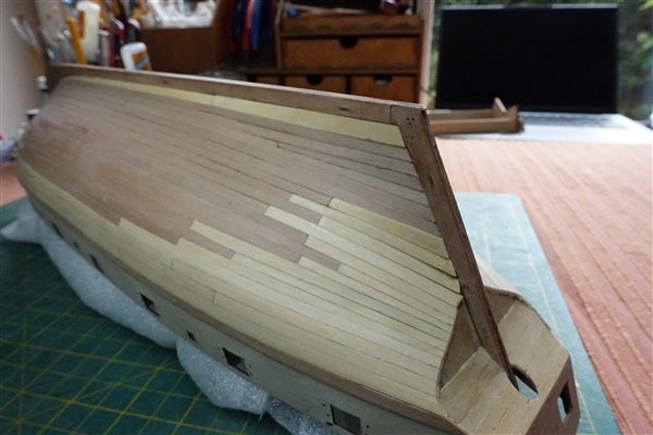
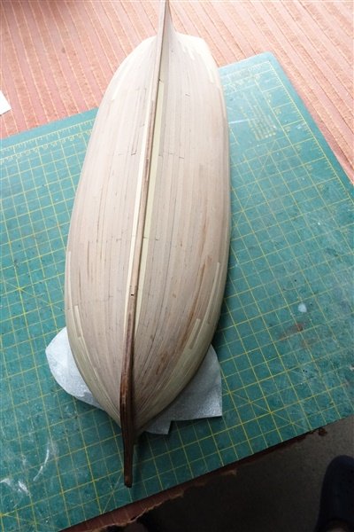
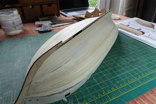
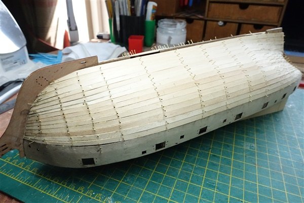
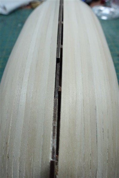
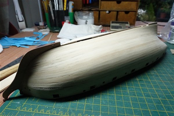
The first layer of planking is completed and sanding and filling started. Planking went pretty well but I had to add a stealer, presumably because I was over enthusiastic with my tapering at the stern. Also apologies due to Chris: 15 planks each side were needed as shown in the photos and as correctly stated on page 17 of the manual (not 16 as I had calculated). The first plank... and some progress shots... First planking complete How far to go with sanding and filling? I assume that small gaps won’t affect the finish of the second planking but any slight ridges between planks need to be smoothed out. There is a 1.5mm gap between the end of the planking and the false keel on the starboard side as shown in the photo below. I will use a wider garboard plank here which I hope will bridge the gap without causing a problem. After initial sanding Side light shows up where more work is needed David

- 114 replies
-
- 9
-
-
- Vanguard Models
- Speedy
- (and 1 more)
-
Thanks Lee, I'm sure you'll enjoy building her. David
- 114 replies
-
- 1
-
-
- Vanguard Models
- Speedy
- (and 1 more)
-
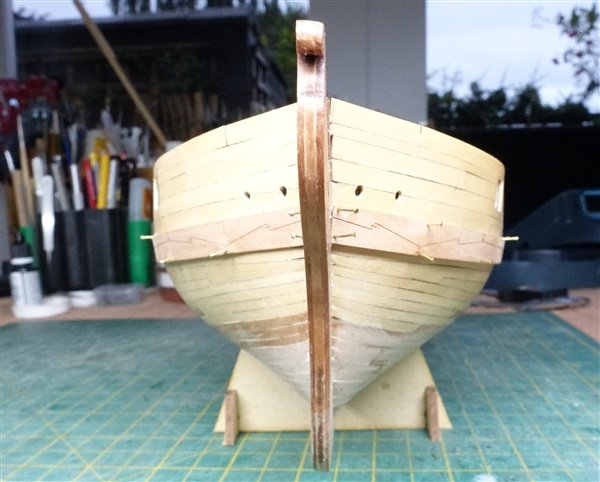
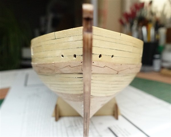
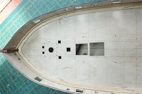
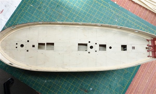
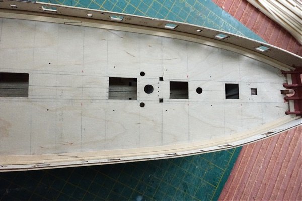
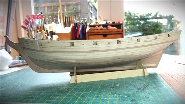
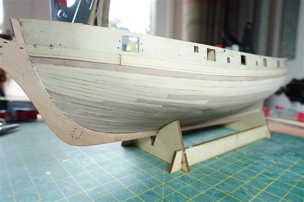
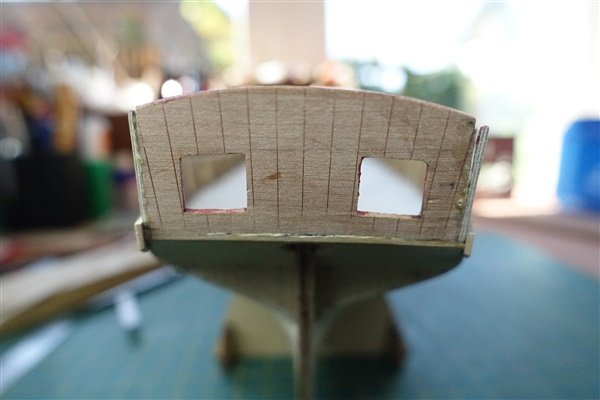
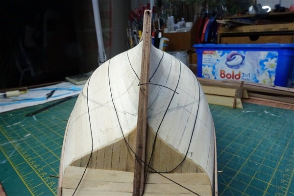
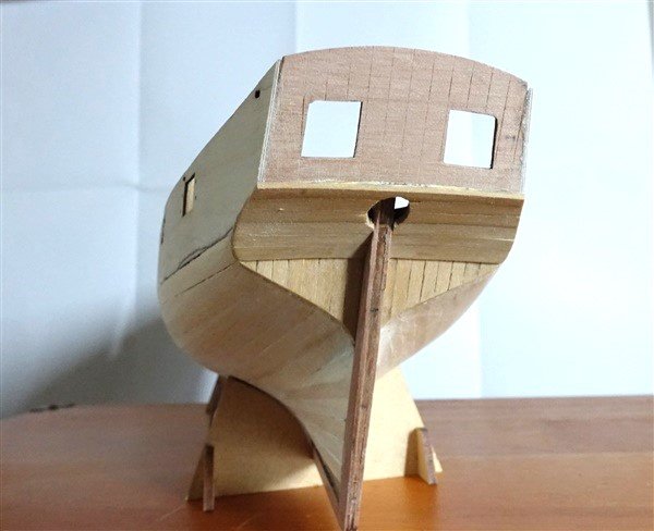
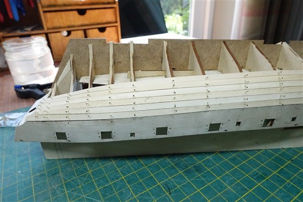
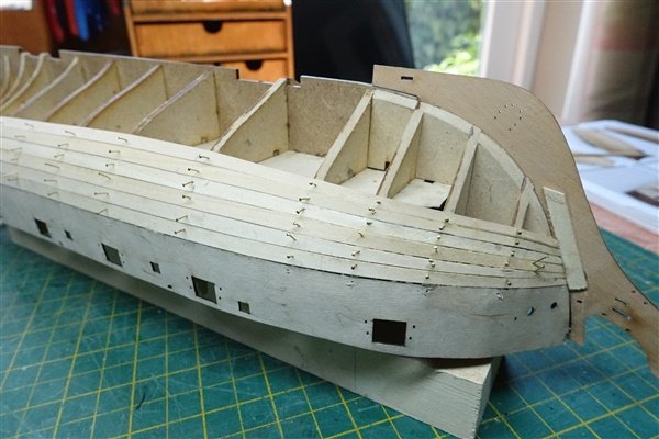
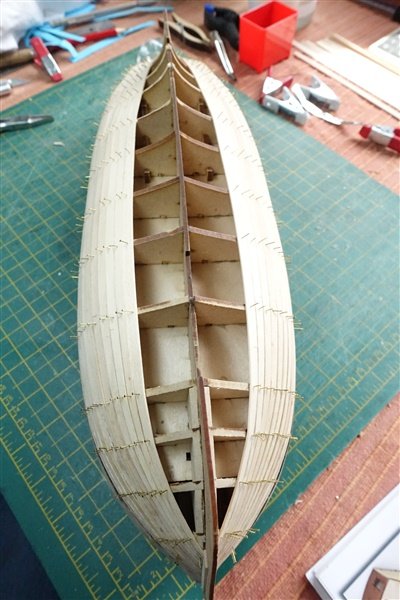
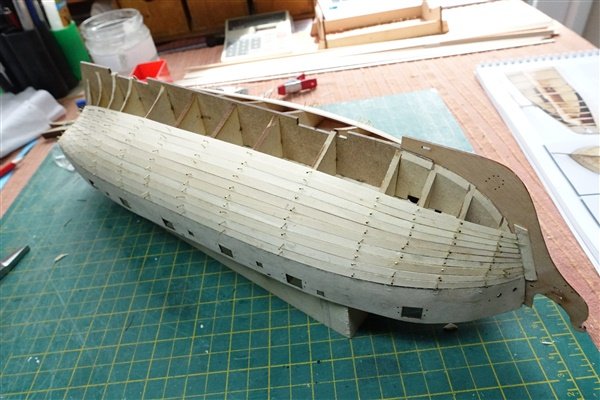
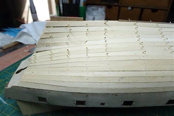
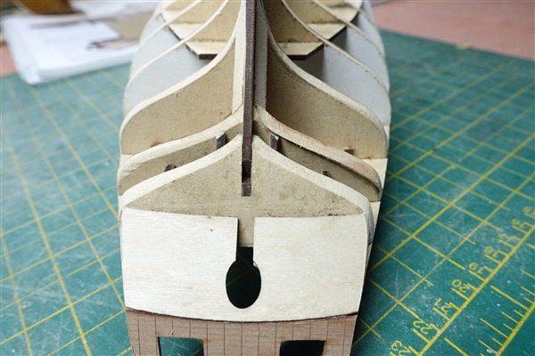
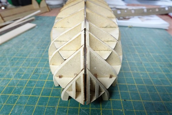
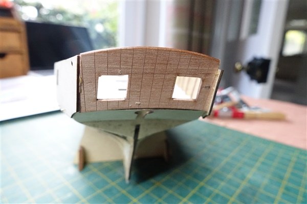
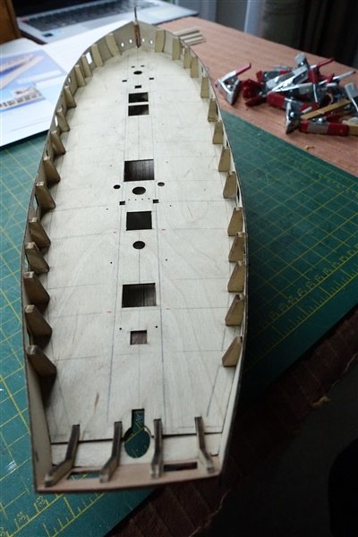
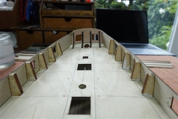
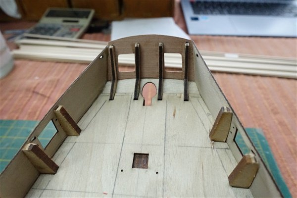
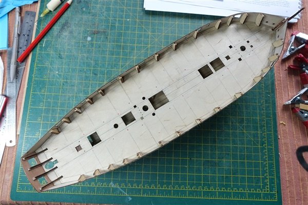
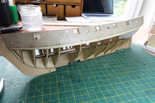
The stern frames are now birch ply and more robust than the previous MDF that I believe was used in previous versions of Speedy. Even so, getting the counter and transom pieces on is a relief and makes the stern section quite robust. The counter pattern was soaked and curved around a jar before fitting and then the transom pattern glued to the stern frames. Hull fairing of the 3mm MDF was relatively quick. I worked it a bit at a time by hand over a couple of days for fear of overdoing it. For some reason BH 14 was low on one side and I had to add a 1mm strip to bulk it out. I think this is my best attempt at fairing a hull so far but the planking will soon let me know if that it true. The gunport patterns were soaked in warm water fitted to the bulwarks and left to dry. The two problems I had at this stage were getting the forward tab of the pattern to fit in the slot on the stem and getting the pins to hold the lower edge of the pattern against the bulkheads. I used a travel iron to improve the contact between bulkhead and pattern. I glued the port pattern without difficulty a few bulkheads at a time again pinning and using heat to improve contact at the lower edge and left it to partially set for half an hour before glueing up the starboard side. When it had all set I noticed the starboard quarter was about 0.5mm too low at the stern so it was partially removed and re-glued. There is still a small difference which I think is due to the transom being slightly off so I may have to rework it. After reworking the starboard gunports The manual says 12 strakes per side are required to plank the hull. I think that this is a typo: the pictures show 15 strakes but I measured the mid frame to be 80mm suggesting 16 strakes of 5mm planks will be needed The first strake of the limewood planking is glued and pinned to each side. The forward end is tapered to half width from bulkhead 5 and the stern left untapered. And so planking continues... David
- 114 replies
-
- 11
-
-
- Vanguard Models
- Speedy
- (and 1 more)