


dunnock
-
Posts
529 -
Joined
-
Last visited
Content Type
Profiles
Forums
Gallery
Events
Everything posted by dunnock
-
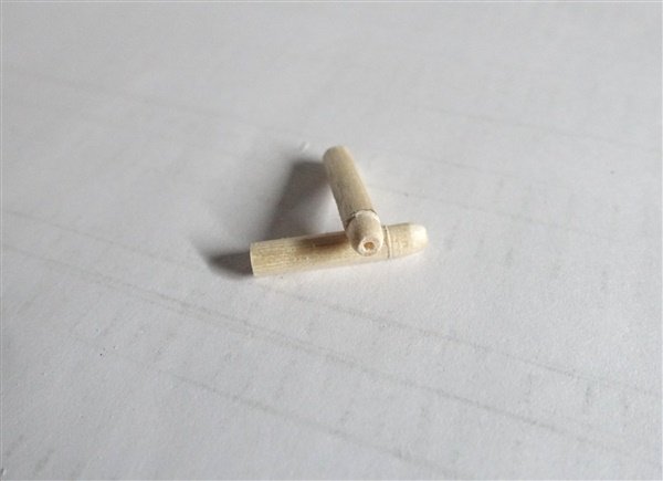
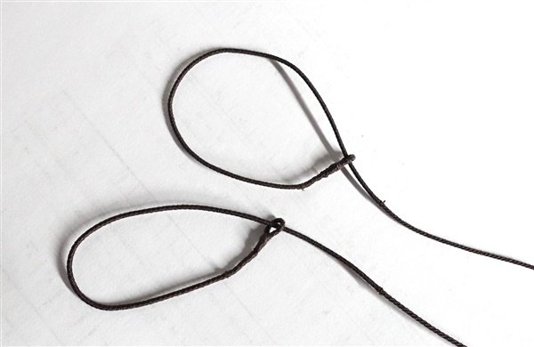
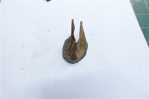
Lower Shrouds and Stays The new jig is made and both fore and main mast shrouds set up. This jig worked much better than messing around with the bits of brass rod that I had used previously. The lanyards are made from 0.4mm thread and will be finally tensioned at a later stage when the standing ring for the lower masts is completed. Moving on to the stays. Based on Steel, the fore mainstay should be scale 8mm and preventer 7mm. I had no 8mm rope in my stock so used 1mm cabled rope. The main stay is given as scale 1mm rope but to maintain a differential between fore and main stays, I’ve used 1.2mm and 0.8 for the preventer stay. Lees says that stays are served to 6’ below the mouse, which in my case meant I served the top145mm of each stay. I’ve started making the mouse (mouses, mice?) for each stay, turning them on my lathe from 4mm dowel. They still need a little more work with the file to achieve a better shape. The other bit of news is that I received this the other day. I’ve been allowed to look at the box but it has now been put away and not to be seen again for another 2 weeks. 🧑🎄🙁 Thanks for the like and comments David
- 114 replies
-
- 5
-

-

-
- Vanguard Models
- Speedy
- (and 1 more)
-
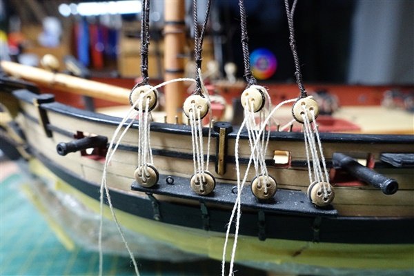
First piece of rigging to add is the gammoning. I used 0.45mm dark brown rope as the nearest I had to 0.5mm from RoS. I was able to get 9 turns in the slot but only 8 frapping turns before I thought they were getting too close to the bowsprit. I also used 0.45mm rope for the stays and shrouds all set up with 3mm deadeyes. Final trimming is left until latter in case I need to adjust tensions. With the bowsprit well lashed down I moved on to the shrouds of the masts but first the pendants of tackles needed to be added. I used 0.7mm rope served along their whole length. According to Lees thimbles had replaced blocks ffor the tackles I messed about using drilled out 4 and 5mm trucks for the thimbles but decided they were oversized and went with 3mm brass thimbles I had from HiS Model. The shrouds are 0.6mm rope. The foremost is fully served and the rest served down to the level of the lower catharpins. I decided that a served length of 50mm looked right. I cut a length of 400mm for each pair of foremast shrouds. The first pair are served for 250mm and the second for 100mm. The main mast shrouds needed to be a little longer and I used 450mm for each pair, The main mast has five shrouds each side and the final swifters are rigged singly to each side. All the shrouds were prepared in one session of serving followed by seizing them around the mast head. It would have been easier to slip the shrouds over the mast if I had not added the cleats and blocks but at least I was able to remove the blocks temporarily. I’ve started turning in the deadeyes – I’m using cable laid rope so the deadeyes are turned in right-handed. Going back to the three shrouds that I did yesterday, I think that they are slightly too close together so I will make an new jig and redo them. Thanks for the likes and for looking in David
- 114 replies
-
- 13
-
-
-
- Vanguard Models
- Speedy
- (and 1 more)
-
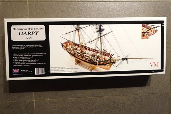
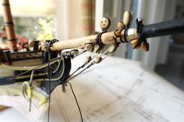
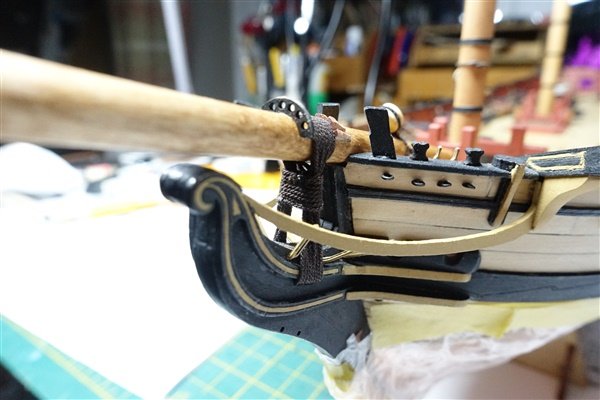
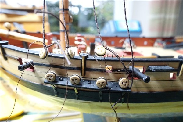
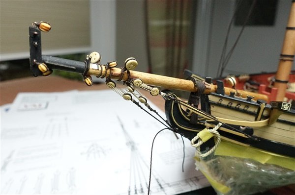
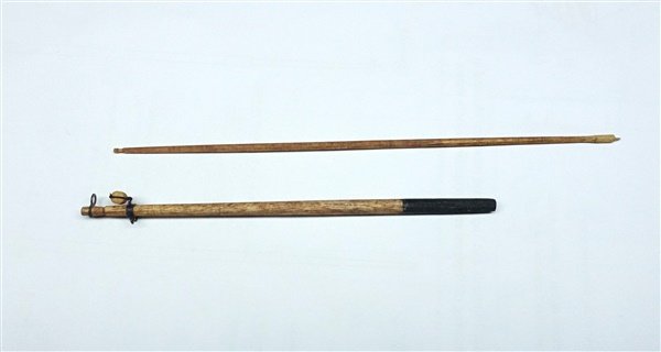
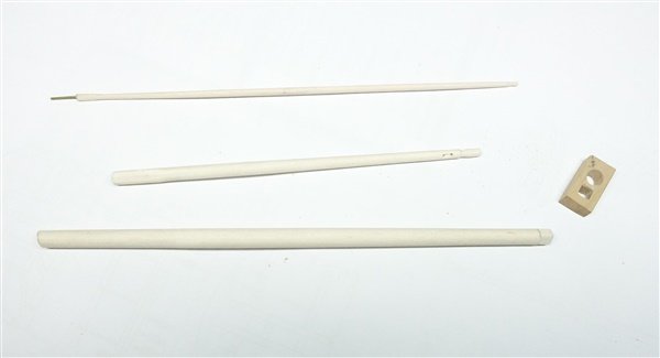
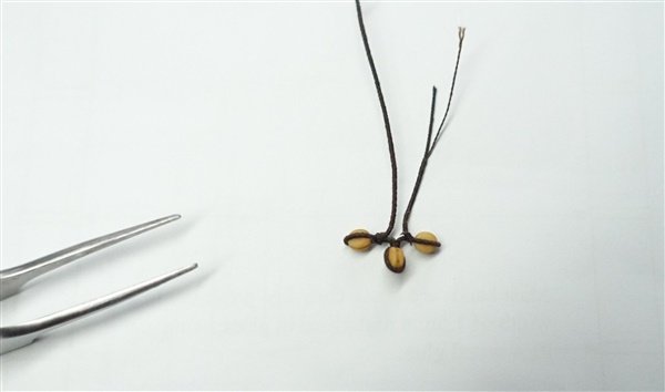
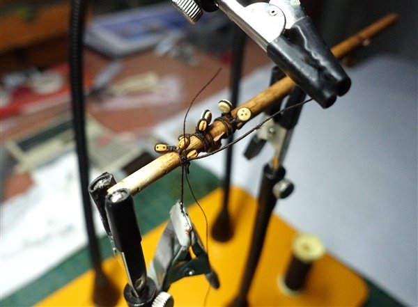
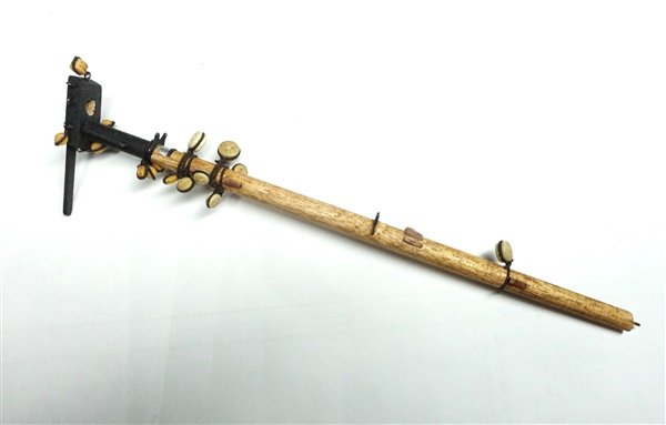
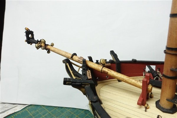
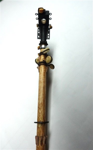
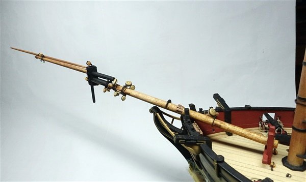
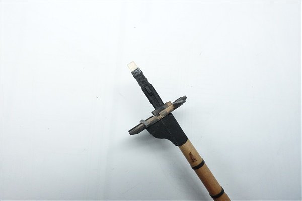
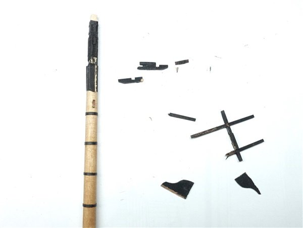
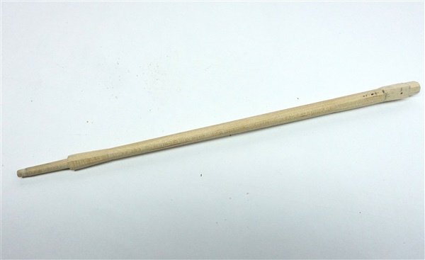
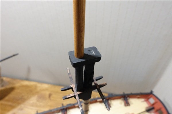
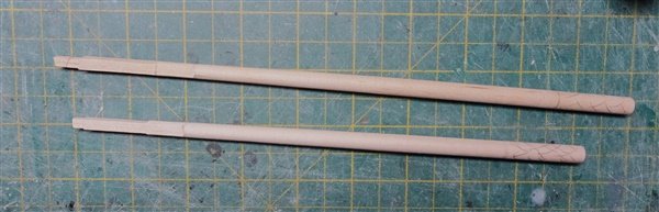
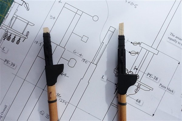
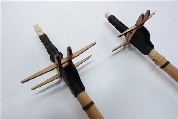
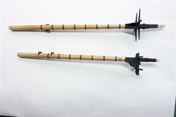
I put in my pre-order for Harpy this week but there is still plenty to do on Speedy and in any case, I have to pretend I don’t know what it is until Christmas 😄 🙄 Bowsprit and Booms The bowsprit is turned from 6mm dowel. The maximum diameter is 1/3 of the length along from the step. I cut a square tenon for the fitting into the cap rather than round. Apart from the gammoning, there seemed to be no way of preventing the bowsprit from moving back through the bitts with the kit arrangement, so I have added a heel. Actually a false heel. I had glued the bitts into the deck so had to remove them to make it easier to work on. I filled the hole in the bitts with a scrap of dowel and glued a second short length of dowel to the after side. The heel piece was sanded and filed to shape. The bitts were refitted and the bowsprit is pinned and glued to the to the forward side. I don’t know if this arrangement is correct but it looks better to my eye than the bowsprit fitting flush into the bitts. Prior to fitting, I added all blocks and cleats. I decided not to use the PE brass fittings for the blocks and instead they are stropped with 0.45 rope. I served one piece of rope in sections of between 40 and 8omm depending on the position and number of blocks in the strop. I was a little puzzled by the rigging plan here because the PE rings showed all the deadeyes on one ring but the plans definitely show at least two strops. For simplicity, I decided to rig the bowsprit stay deadeye on one strop, the two side stays on another and the fore stay on a third. I used a similar arrangement for preventer stays and 3mm blocks. Thank goodness for quadhands... I used the PE parts for the fairlead and jibboom saddle and just forward of this I added the spritsail yard saddle I made from a wine bottle capsule. I hope it looks similar to the lead sheet used in real life but may need toning down. I wasn’t able t modify the bowsprit cap to take the squared tenon and made a replacement from boxwood sheet. I have also scratched the dolphin striker from a piece of 1mm walnut which looks a more substantial piece now. Jib and flying jib booms are made from appropriate sized dowels. The jib boom has an octagonal section 14mm long at the after end and a 3mm length at the forward end. I cut a heelrope sheave and hole for the lashing on the inboard end and a sheave for the outhauler at the outer end. The flying jib boom gets very delicate on the lathe when working it down to 1.4mm on far end. There is a short octagonal section on the inner end. I’ve not been brave enough yet to cut sheaves in this thin spar but I may attempt it when it’s time to fix it in place. The bowsprit is now pinned and glued in place and it’s time to start rigging. jib and flying jib are loosely fitted but they look pretty vulnerable out there so will be removed until later. Thanks a lot for looking in, the likes, comments and general encouragement. David
- 114 replies
-
- 8
-
-
- Vanguard Models
- Speedy
- (and 1 more)
-
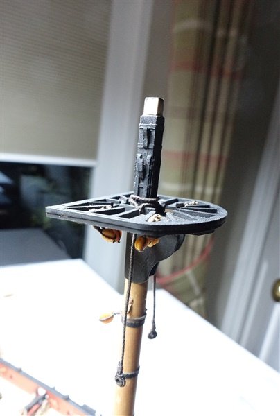
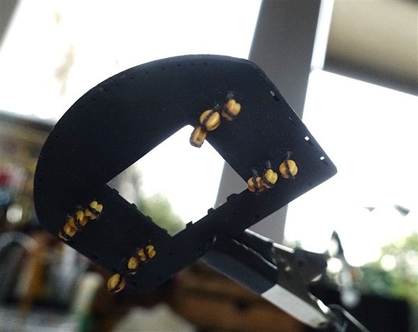
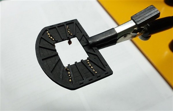
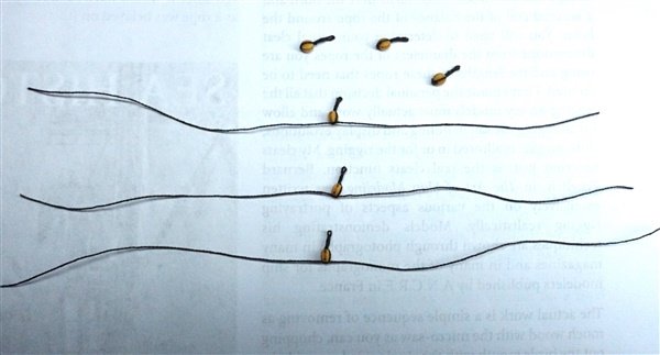
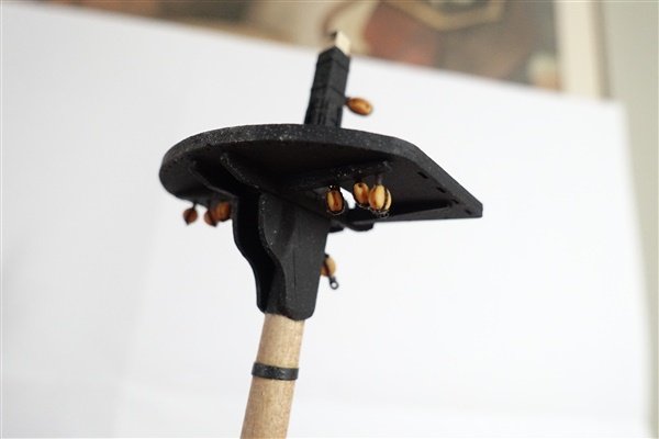
Thanks to everyone for the likes and comments. I’ve added all the blocks and deadeyes to the lower masts before they are finally fitted to the model. I’m using the latest ‘boxwood’ resin blocks from Syren which are very nice and detailed. I’ll use the deadeyes supplied with the kit although some sorting is needed to pick those with the best distribution of holes. I’ve used dark brown RoS cotton ropes, served with Gutterman thread for the strops for all the blocks and deadeyes around the mast. The blocks below the tops are shown suspended from eyebolts in the crosstrees on the plans. According to Lees and Petersson, they would be suspended from wooden pegs on the floor of the tops. This arrangement is quite fiddly and space is tight but easier to do before the tops are fitted on the mast. Strops are 0.4mm Gutterman polyester thread. They need to be long enough to pass through the floor of the top and leave the blocks clear of the crosstrees. A couple of coats of matt varnish stiffen the long strops and fix the pegs in the eye of the strop. I’m leaving the guard rails off until the rigging is almost complete to make access easier and because I'd probably break them if I fitted them now That completes the fittings on the lower masts. I’ve made a start on making the bowsprit, jib and flying jibbooms which I’ll complete before beginning the standing rigging. David
- 114 replies
-
- 9
-
-
- Vanguard Models
- Speedy
- (and 1 more)
-
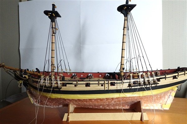
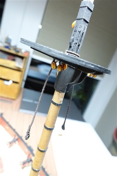
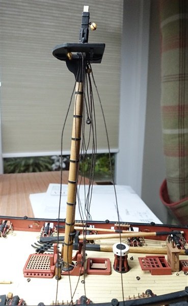
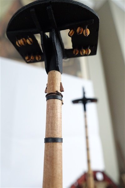
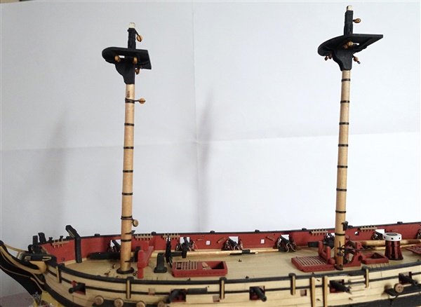
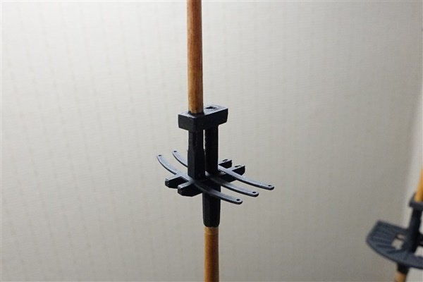
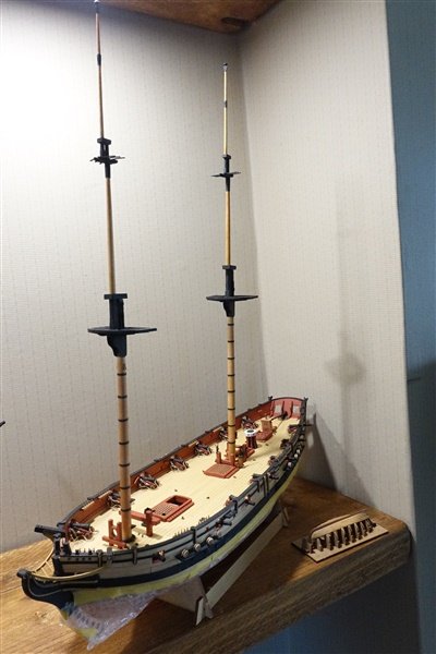
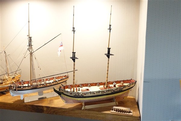
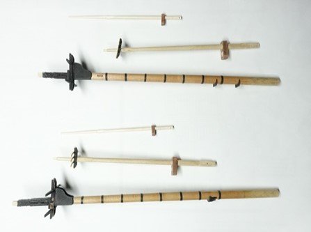
It's been a while since I posted. I have been working on the masts but I've also had a short break in Norfolk looking for birds that proved elusive. Anyway I've now completed the fore and main mast sections According to Lees’ and Petrejus’ plans for topmasts and topgallants, all have a square section heel and are octagonal between top and cap. The top mast was made from 8mm dowel and topgallant from 6mm to enable the 5 and 4mm octagonal sections to be made. The excess was planed square to begin and then finished with files, sanding sticks and then the lathe for the round sections. I wish I could start with square sections for masts and yards but I can't find any that cover the full range of sizes needed. Top rope sheaves are drilled through the octagonal sections from starboard through to port faces. The topmasts, like the lower masts are finished square at the cap. I thought about whether to make the caps from scratch but found I didn't have any sheets of the right size so decided to modify the caps supplied. I plugged the round hole with a piece of dowel and then cut a new square hole using a 0.6mm drill to perforate around the edge. A scalpel was used to roughly cut out the hole and then I finished it off with a file. The corners are rounded off. I’ve still to add the four eyebolts around the underside. I was taking some photos after I had finished but before painting when I had a little accident. I dropped my camera on the foremast and smashed the bibs and crosstrees. Luckily they were salvageable and the parts glued together well. I liked the way that the tops for the topmasts are made up. Using PE brass crosstrees and pearwood trestletrees, they are simple to put together and the holes in the brass for topgallants stays and shrouds are more robust than if they were in wooden components. I’ve dry assembled the masts and put them in place to get a feel for the finished size of Speedy and to check she’ll fit on the new shelves. Thanks for looking in and the likes and comments David
- 114 replies
-
- 10
-
-
- Vanguard Models
- Speedy
- (and 1 more)
-
Nice planking Andrew. I bought some proportional dividers a while ago but couldn't get on with them. Maybe I'll give them another try. David
- 35 replies
-
- 2
-

-
-
- vanguard models
- Adder
- (and 2 more)
-
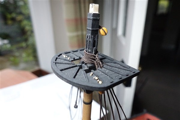
Lower Masts I will make all the masts and yards from ramin dowel stained or painted as appropriate. The lower masts are both made from 8mm dowel. I first marked out, planed and filed square the head sections. Then using my Proxxon lathe, tapered the round sections according to the proportions at each quarter given in Lees. Both lower masts were stained antique pine before adding the hoops. According to Lees, the diameter at the hounds is 4/5 of the diameter at the deck equal to 6.4mm. This is slightly less than given on the plans, so the hounds needed a small amount of trimming before they were fixed. I also scribed a false scarf joint to indicate the presence of the bibs. It's not apparent in the photo but can just about be seen with the naked eye. The main mast is canted aft but the top must sit parallel to the waterline so the hounds are set at an angle. The foremast is vertical, so in this case the top sits square to the mast. Should a front fish and cheeks be added to each mast? I decided to follow the plans and leave them off. I have, however added hoops and battens to the mast head. For the hoops I used heat shrink tube and the battens are made from 1x1mm boxwood strip. Adding these before the crosstrees was a mistake though. If I made up the trestletrees and crosstrees, they would not now go over the mast head. I had to glue together one trestletree and crosstree and complete the assembly around the mast: a bit awkward but it works. The cap should have a square hole for the lower mast according to Lees. I made the tenon 4mm square rather than round. If I were following Lees exactly, it should be 4.5mm across and 4mm front to back but I’m happy that 4mm square is a sufficient approximation. Thanks for looking in David
- 114 replies
-
- 7
-
-
- Vanguard Models
- Speedy
- (and 1 more)
-
Thanks Andrew. They are all only brush painted using Admiralty paints There is a camber on the combings and gratings and I added a couple of bands to the elm tree pumps. A fuller description of making up the fittings is in post#19 David
- 114 replies
-
- 2
-
-
-
- Vanguard Models
- Speedy
- (and 1 more)
-
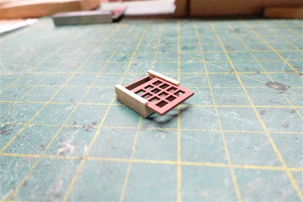
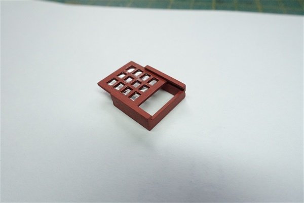
The centre line fittings are all in place using the kit parts. The only modification I made was to the skylight, although the mast partners and stove chimney benefit from a little rounding. According to Chris’s narrative at the beginning of the manual, so little headroom in his cabin that Cochrane was in the habit of opening the skylight and poking his head out shave. I thought I would have a go at simple modification and create a sliding skylight. I hope that this is the correct arrangement. I used 5 x1.5mm strip and cut a channel for the skylight to run in then replaced the kit sides with the modified ones. I don’t have a mill so used scalpel and file to create the channel. I bought some Micro Kristal Clear to glaze the lights. It’s the first time I’ve used it so the glazing is not perfectly flat but I’ve convinced myself that from a distance it looks like blown glass. Thanks for looking in David
- 114 replies
-
- 14
-
-
- Vanguard Models
- Speedy
- (and 1 more)
-
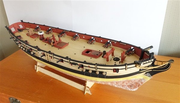
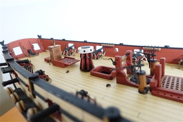
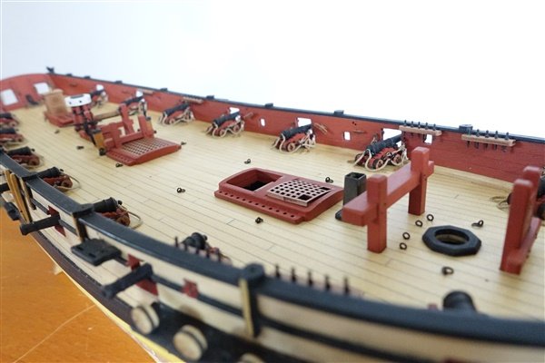
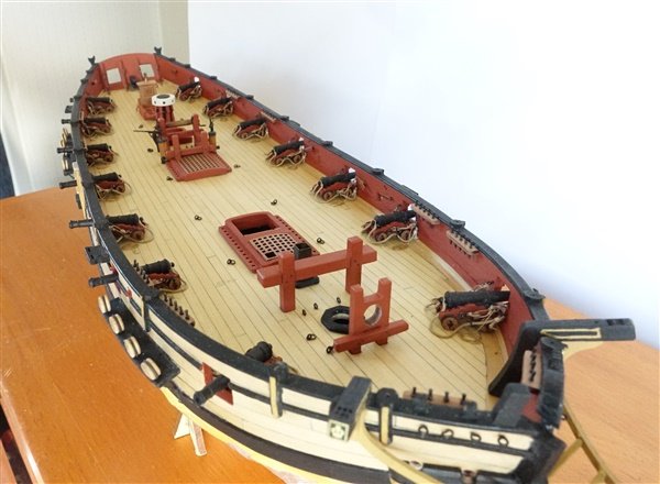
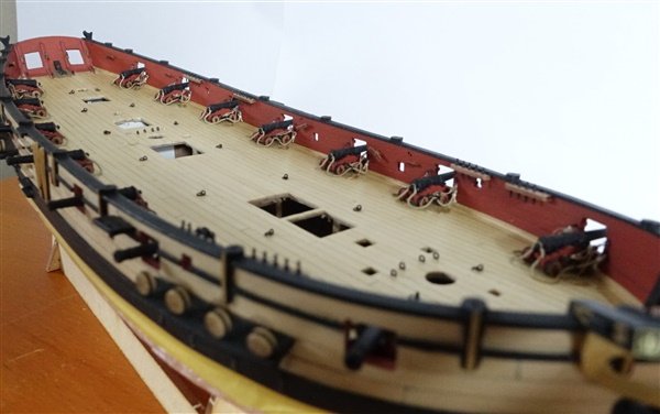
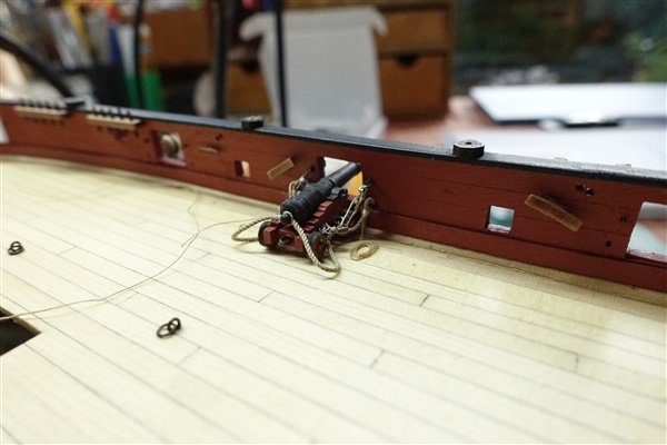
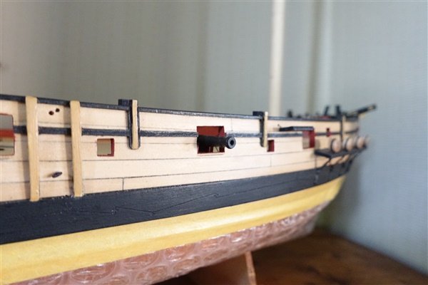
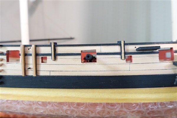
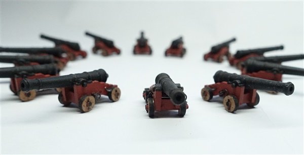
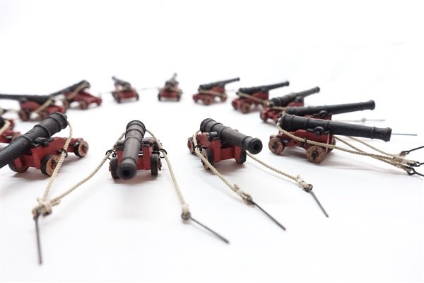
The guns are now in place. I have pinned each one to the deck using lengths of 0.6mm brass rod. The RoS breech ropes lie nicely without any real manipulation and without need to spot glue them in place. A broadsides worth of 'random' coils The falls of the tackles have been left loosely flaked on the deck. Unfortunately the dilute matt varnish that I used to hold the coils together has darkened the ropes but there’s not much I can do about that and it’s not easy to see the contrast between tackle and fall. Speedy is now beginning to look like a ship now that all the guns are on board. Adding the deck fittings is the next stage. David
- 114 replies
-
- 11
-
-
- Vanguard Models
- Speedy
- (and 1 more)
-
Fantastic result Andrew: really well done. BTW, I've had a word with Kate about flag painting at mates' rates 😉 David
-
November release - that's great just in time for Christmas. I'll be asking Santa to put one in my stocking 😊 David
-
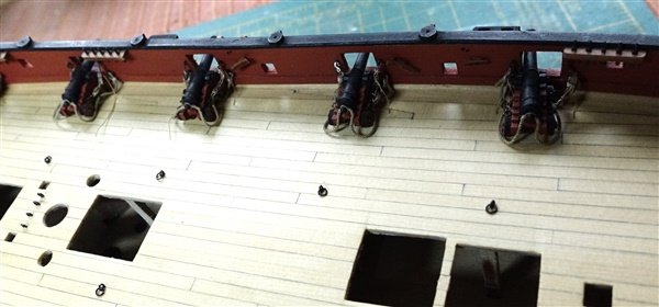
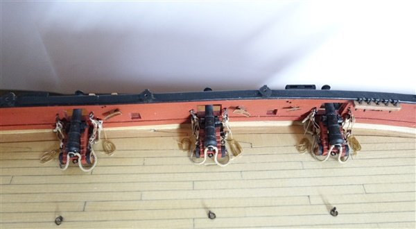
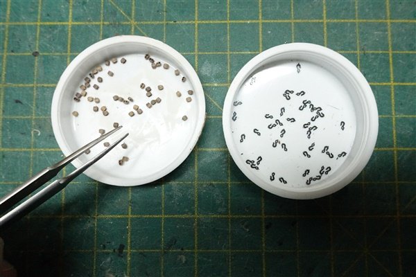
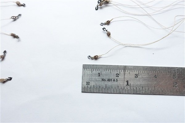
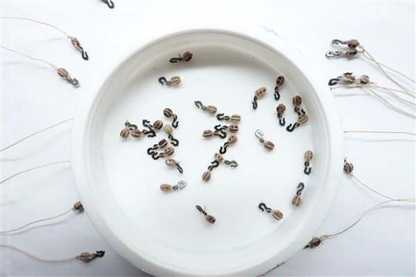
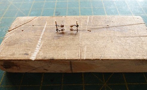
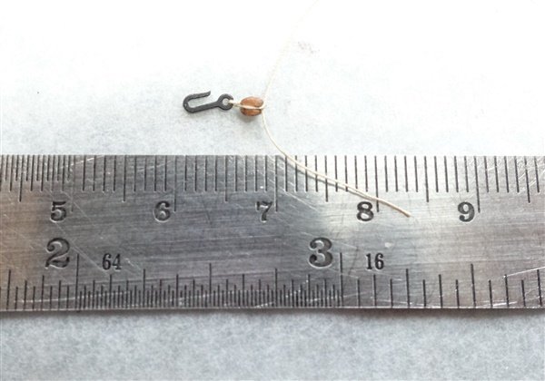
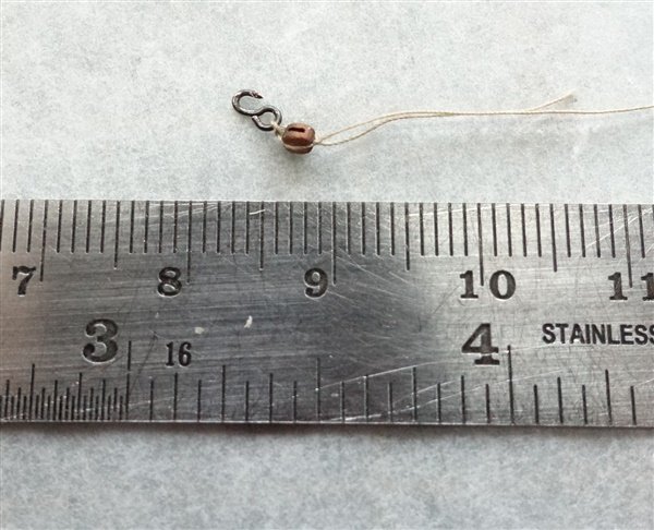
The hooks have arrived - they are really small, I also ordered some 2mm PE etched eyebolts at the same time. They seem a better match for the hooks than the Amati eyebolts and I will use them for the bulwark fixings. I have used single 2mm block for the tackles which I think is appropriate for a 4-pounder gun and 0.1mm Gutterman thread for the ropes. I’m indebted to @Thukydides and his Alert log for his method of attaching these small hooks and ropes to such tiny blocks which I modified only slightly by tying and extra half hitch on the tackle rope to create the semblance of an eye. I’m glad there are only 14 guns but 56, 2mm blocks and hooks is still quite a challenge and I draw the line at another 28 for the training tackles! To obtain the correct distance between blocks for the port tackles, I set up one gun with tackles and used this distance to make a simple jig to set the distance for the rest. I’m undecided about whether to show the tackle falls frapped as I have before, or to try to leave them loosely flaked on the deck. I’m leaning towards the latter but I still have to play about with making the thread look less ordered. The gun is not fixed yet but a pin as been glued to the underside of the bed and will be glued to a hole in the deck. It seems from this set up that the quoins I made would depress the gun from it’s neutral position in the centre of the port so I will not be using them. I wonder if this is because I chose to plank the deck rather than use the kit’s engraved part? Thanks for all the likes and for looking in. David
- 114 replies
-
- 8
-
-
- Vanguard Models
- Speedy
- (and 1 more)
-
Thanks Andrew but I think that I may have got my terminology wrong. Just to clarify, I used the paper disposable lens wipe, not the fabric ones you get with every pair of spectacles. David
- 114 replies
-
- 1
-
-
- Vanguard Models
- Speedy
- (and 1 more)
-
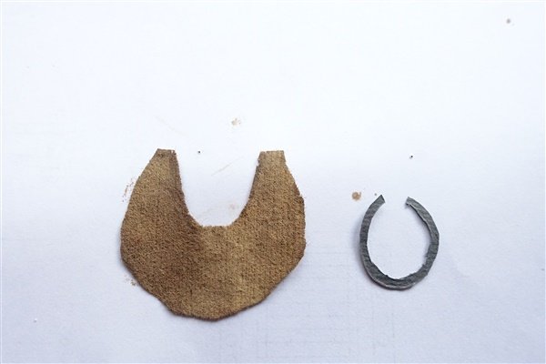
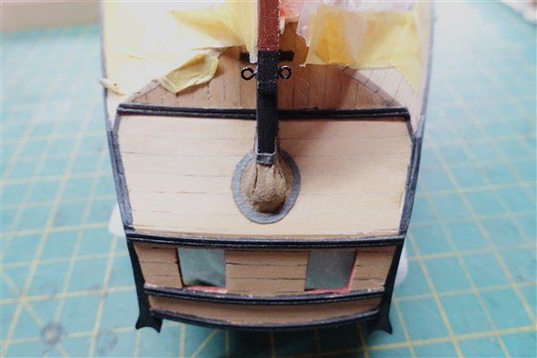
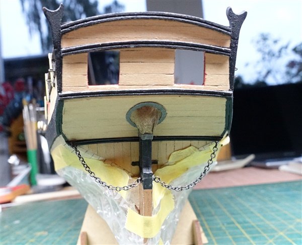
While I’m waiting for hooks to arrive from HiS Model, I thought I’d have a go at finishing off the stern with chains and a rudder coat. The rudder was made a little while ago. While I did taper both rudder and sternpost towards the keel I have forgotten to make the chamfer at the edge where they meet. Too late now. The horseshoe collar is cut from a piece of card slightly larger than the opening. I made the rudder coat from a piece of non-woven lens cloth which has a nice leather-like texture when painted. I cut it to an approximate size and shape which after the third attempt, seemed to be about right. Collar and coat are glued together with pva and then glued to the counter. I’ve not done it before but I used @Blue Ensign's technique of stuffing the coat with cotton wool to give it some fullness. It was then just a question of trimming and finishing gluing to the rudder and sternpost. Rudder chains are added to finish off David
- 114 replies
-
- 9
-
-
- Vanguard Models
- Speedy
- (and 1 more)
-
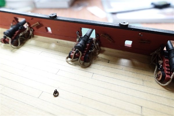
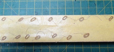
Going back to the guns, I’ve added the ring bolts to the carriages and pins to the axles. Ideally the axles would have been slightly longer to allow more room to drill the holes but I managed with only slight damage to a couple of the axles, easily covered up when they were repainted. The breeching ropes are made from 0.7mm rope seized to 2mm ring bolts. I made them 105mm long to allow for room to make the seizings and give a final length of 85mm – slightly longer than 3x the barrel length. The rope is split at the centre, fed over the button and fixed with dilute matt varnish. I did some experimentation with the port tackles using 2mm blocks but the hooks I have looked oversized. I also tried making up some hooks from 24gg wire but again I’ve struggled to make them look in proportion so have ordered some 3mm hooks from HiSModel. While I’m waiting for them to arrive, I pass on to other things... Thanks for the likes and for looking in David
- 114 replies
-
- 7
-
-
- Vanguard Models
- Speedy
- (and 1 more)
-
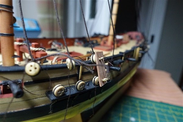
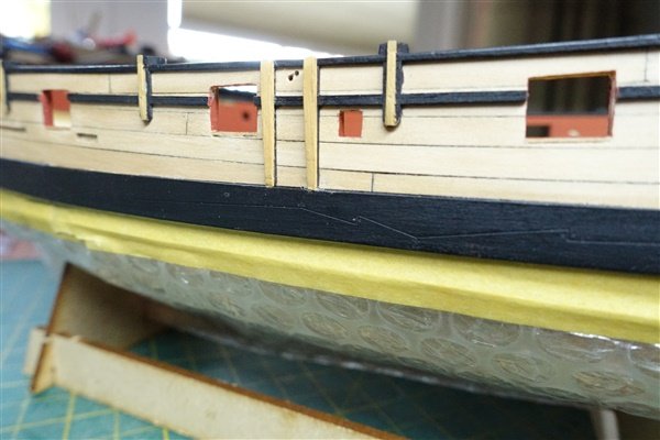
I’ve added the channels, chains and deadeyes. I used the kit parts but scraped a moulding around the edges of the channels which after painting them black, is hardly visible. The brass PE chains and deadeye links were blackened in the usual way with Birchwood Casey Brass Black. I put some tape below the channels and marked off the positions for the chain fixings in the usual way using a thread fixed at the height of the head on temporary masts and leading down through the deadeyes. I was concerned that with all the messing about with the wales that the chains might fall in the wrong place but it has worked out quite well. Now it’s back to rigging the guns that I made up some time ago. I will try to rig them with at least breechings and side tackles but rigging 2mm blocks and hooks is going to be a challenge. Thanks for looking in David
- 114 replies
-
- 9
-
-
- Vanguard Models
- Speedy
- (and 1 more)
-
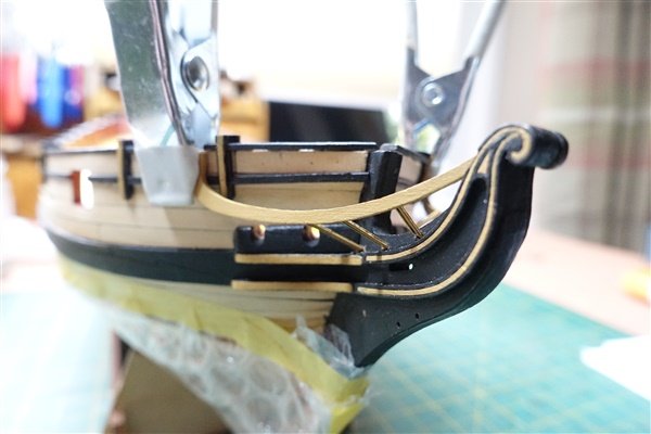
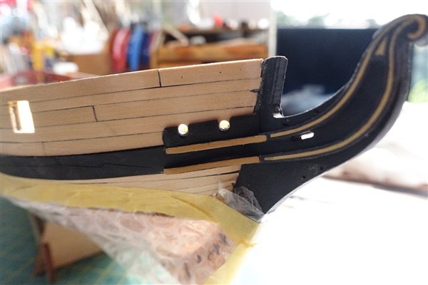
I’ve been finishing more of the outer hull fittings including the steps, cathead and cathead knee. I wanted to use boxwood for the steps to match the outer hull planking. I cut 2 and 1mm strips from a sheet and used these to cut the treads and a ledge for better support. A strip of tape kept the steps in line vertically and a copy of the side elevation with the steps cut out ensured the steps were correctly spaced. The cathead was made up from the kit parts although I left off the pear end cap and just added the PE crown motif. A little fairing was required on the inner surface of the leg to match the line of the hull. I filed out the sheaves a little more and drilled them through. The knee was a little more challenging. I wanted it to look like it blended in to the main rail a little more then a simple bracket. I didn’t have any 5mm pieces of sufficient depth so I hade to make a sandwich out of some 3mm thick sheet and some 10x1mm strip which would give me sufficient depth. It was then a matter of cutting and shaping to fit and blend as best I could into the main rail. Ideally I would have modified the rail too to look more like the side elevation of the hull rather than the front profile on plan sheet 4 but I’m fairly happy with the result as it stands. David
- 114 replies
-
- 6
-
-
- Vanguard Models
- Speedy
- (and 1 more)
-
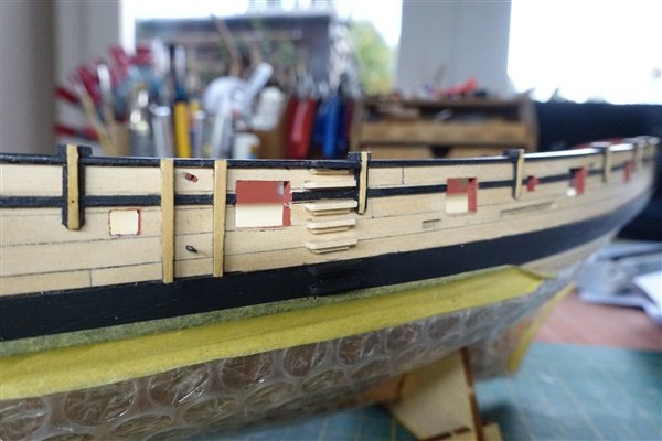
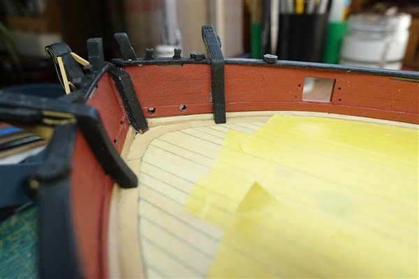
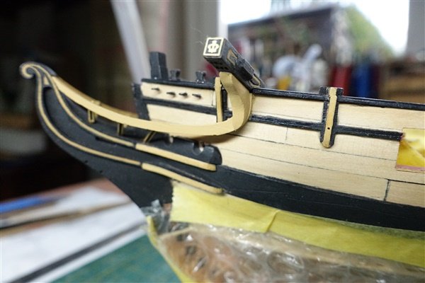
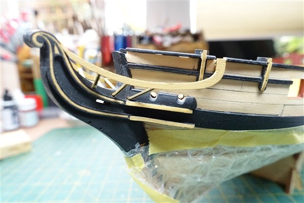
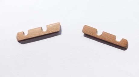
Thanks as always to everyone for the likes. I’ve been working towards completing the outer hull with rails, pivot gun posts and the head works. The upper rail and lower part of the swivel gun supports are all one piece. The length of the hull is covered in five sections with some running across the gun ports making it easier to maintain the correct line. Swivel gun post timbers and the fenders are then added. I tapered the posts towards the base rather than leaving them square. The fenders are pearwood strips which looked too flat to my eye so I made them from scratch with a bit more of a profile. The swivel gun bases finish off this part of the build. Moving on to the stern. I planked the transom with boxwood strip to match the counter. I know it’s probably not as it should be and not as shown in the manual but I preferred to go with horizontal planking. The boom crutches have to be filed down at the base to match the counter side patterns and chamfered on the back to closely fit the bulwarks. Some necessary tidying up of the stern is highlighted by this close up. Finishing the head works was tricky and took quite a while to match the main rails and the head timbers. The rail is chamfered where it fits against the side. Removing the part of the capping rail where the catheads will sit makes this easier to check. The head timbers are PE brass parts that feed through slots in the knee and are bent up to meet the rail. Filing the ends of the ‘timbers’ gets a closer fit to the rail. The catheads are next up. David
- 114 replies
-
- 7
-
-
- Vanguard Models
- Speedy
- (and 1 more)
-
Well done Dan, a lovely model and your rigging looks excellent. David
- 146 replies
-
- 2
-
-
- Adder
- Vanguard Models
- (and 1 more)
-
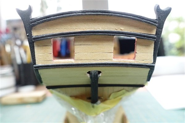
The hair brackets and bow cheeks were added after painting off the model. I felt the hawse bolsters looked a little flat and could be improved, so I remade them from some 6x2mm pear strip to give them a bit more shape. The capping rails proved slightly tricky. I drilled holes for the pins through the rail and into the hull but still had great difficulty in making the pins hold. Once glued, I removed the pins rather than cutting and filing them back. I had to re-glue some sections but all is now holding together well. The counter side-timbers were tricky to place and I was a bit nervous about cutting back the wale. Once done, I realised that the wales were not correctly positioned at the stern. In a previous post, I mentioned that based on measurements taken from the plans, I thought the marks I had made when planking the upper hull to indicate the position of the wales were wrong but when it came placing the stern side timbers, I realised that I was correct in my original marking. In the end, I removed the after section of the wale, fitted the side timbers first and then married the wale to the side timbers. It was a lot of messing about and required some filler between wale and side timber but I’m happy now that the stern looks as it should. Thanks for looking in David
- 114 replies
-
- 10
-
-
- Vanguard Models
- Speedy
- (and 1 more)
-
Thanks Andrew. The waterline template is sort of suggested on Sheet 4 - Profile Plans but I think I saw the idea somewhere else on these forums but can't remember where or who so my apologies to whoever it was. David
- 114 replies
-
- 1
-
-
- Vanguard Models
- Speedy
- (and 1 more)
-
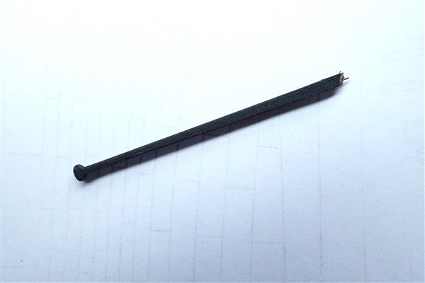
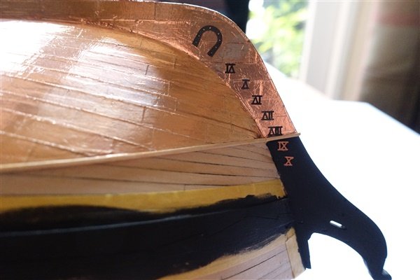
The rudder comes as a three-part sandwich. Once glued up, I painted the edges copper and the portion above the waterline matt black. The wales and stem were painted black at the same time. Copper ‘plates’ were added and trimmed up. The PE pintles looked a bit flat so I borrowed Andrew’s @AJohnson idea from his Trial and slipped on pieces of styrene tube to flesh them out. The pintle braces were cleaned up and painted copper then glued with small dots of CA. I drilled holes for the pintles in the stern post and temporarily fitted the rudder and used Tamiya tape to work to for fixing the gudgeon braces. I have added eyebolts for the rudder chains and used heat-shrink tube for the bands at the top of the rudder. Finally the tiller was put together from the two pieces of 1mm pear and given a bit of shaping. As well as the recommended pin to fix the tiller into the rudder, I cut a small tenon to match joint. The rudder and tiller are now bagged up and put away for fitting latter in the build. I finished off this part of the build by adding blackened dovetail and horseshoe plates and finally the depth markers. The sharp-eyed might wonder where XI has got too – probably in Severn-Trent’s sewerage system by now. (Note to self to remember to put the plug in the sink when rinsing off these tiny parts). Thanks for the likes and kind comments and for looking in. David
- 114 replies
-
- 6
-
-
- Vanguard Models
- Speedy
- (and 1 more)
-
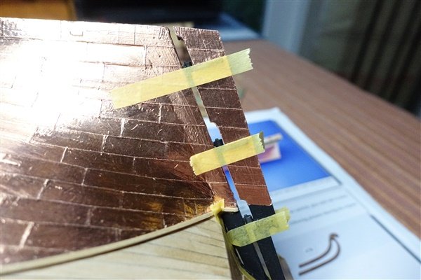
Thanks Andrew, Tape is so much easier and flexible enough that you don't have to make any cuts at the stem. I just trimmed it with a packing knife - the sort with the break-off blades. The tape also sticks well once rubbed down with a smoothing stick. The only caveat is that it seems quite soft and vulnerable to damage during the rest of the build. I might try masking it all off to protect it. David
- 114 replies
-
- 1
-
-
- Vanguard Models
- Speedy
- (and 1 more)
-
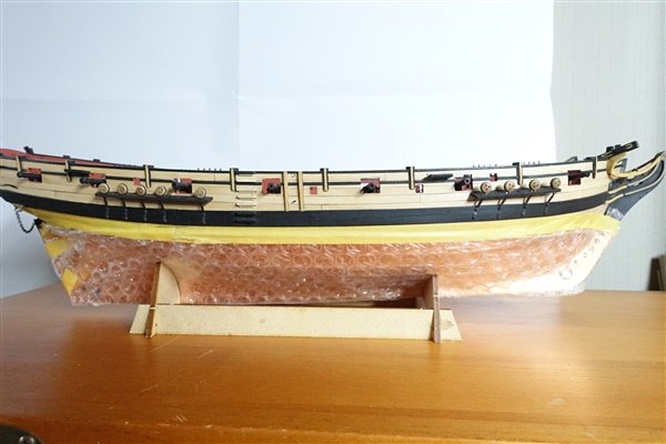
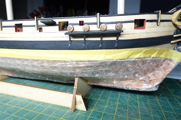
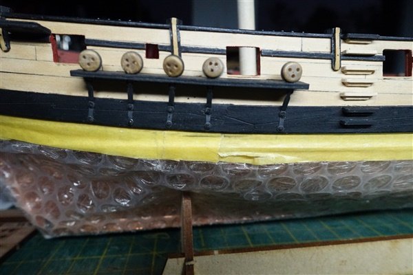
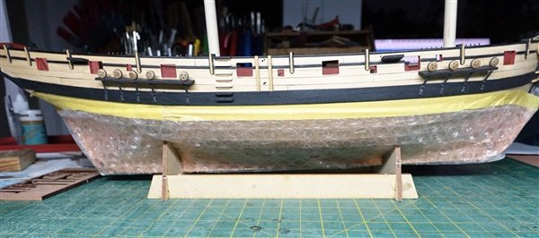
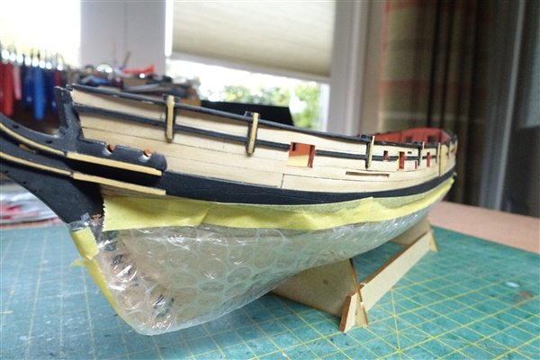
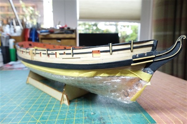
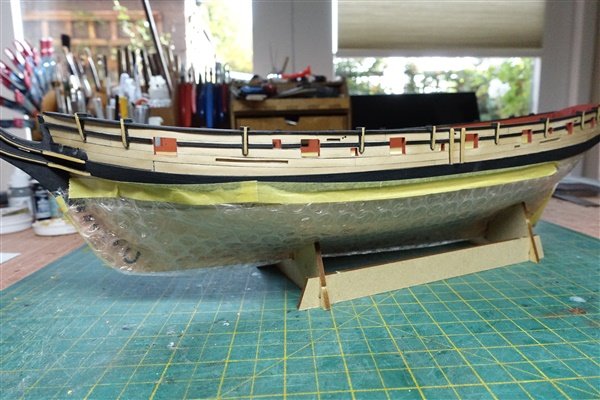
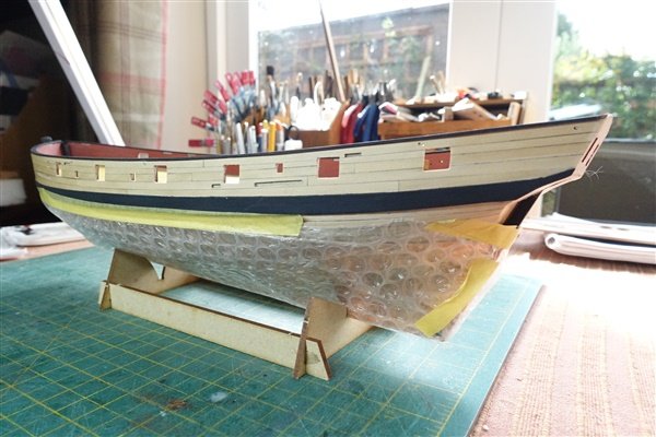
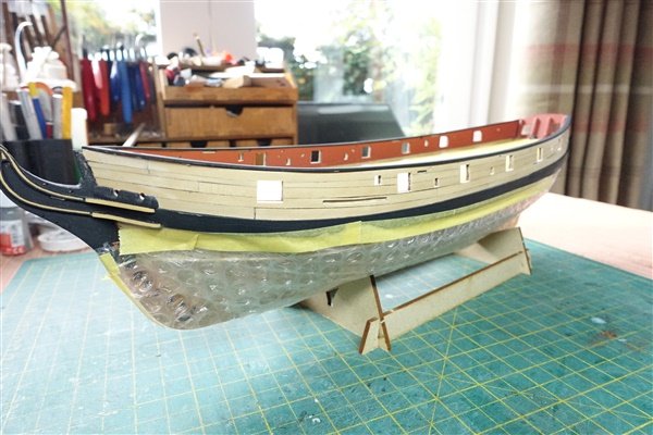
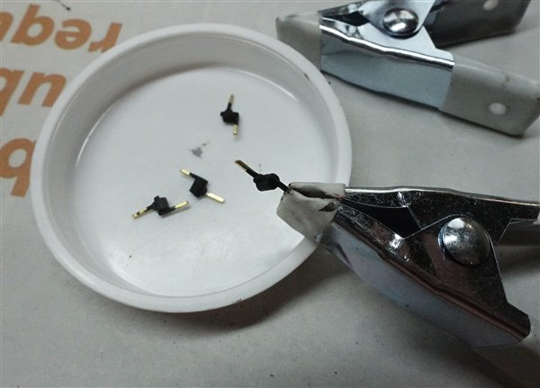
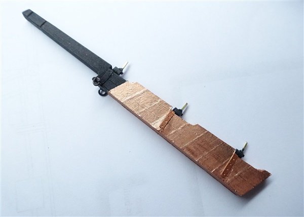
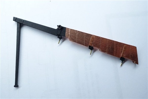
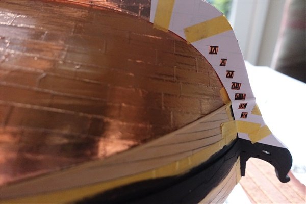
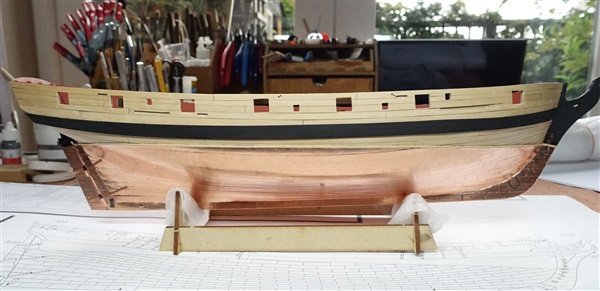
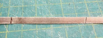
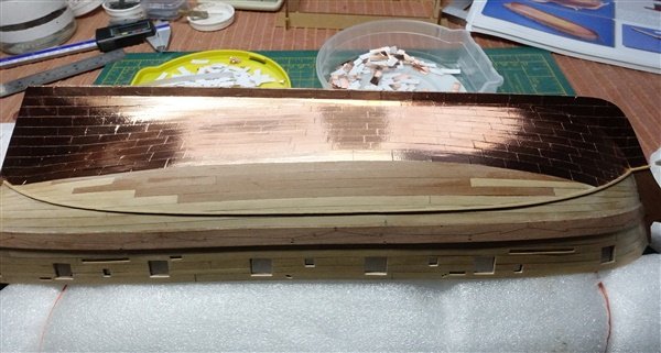
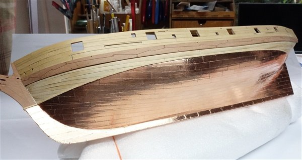
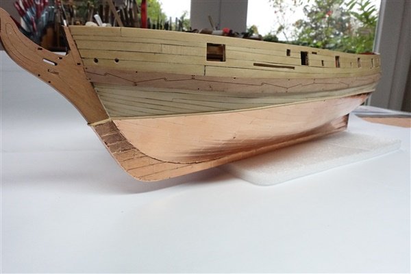
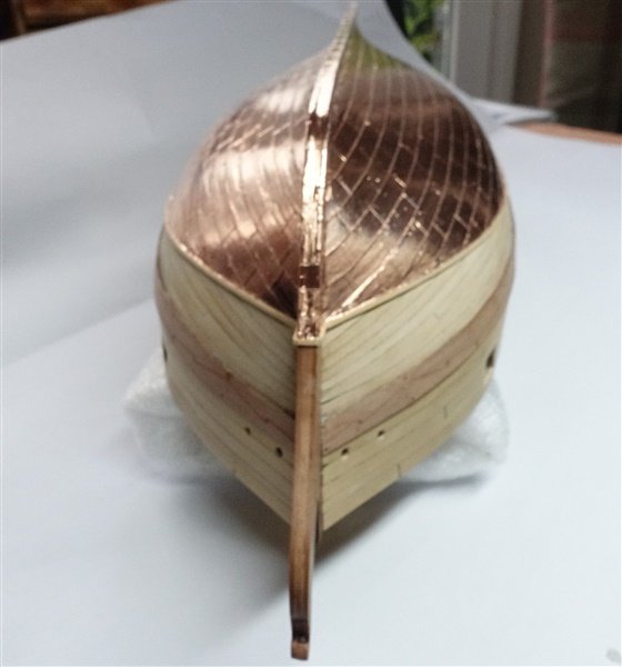
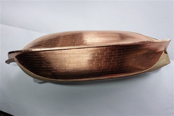
Thanks everyone for following and for the likes. Copper plating of the hull is complete. Tape is so much easier to apply then the copper plates that I used on Diana and I think that the result is probably better. I don’t think the lack of dimples depicting nailing is a great loss to the overall effect. I was a bit concerned about the appearance of the tape before I started as it was wrinkled down each edge – perhaps some roller problem on the tape slitting machine - and there were a number of folds of the tape along the length. I say this only as an observation and to reassure other builders who might see a similar issue. However, when it came to laying the ‘plates’, all these problems were removed by rubbing down with a smooth rounded stick. Now half-way down the port side Completed hull: Now that it’s finished, my worry is trying to protect the surface during the rest of the build. The copper tape is very soft and easily marked. David
- 114 replies
-
- 13
-
-
-
- Vanguard Models
- Speedy
- (and 1 more)