stuglo
-
Posts
707 -
Joined
-
Last visited
Content Type
Profiles
Forums
Gallery
Events
Everything posted by stuglo
-
Swan-Class Sloop by Stuglo - FINISHED - 1:48
stuglo replied to stuglo's topic in - Build logs for subjects built 1751 - 1800
24 Posted 13 hours ago "TFFM suggests 56 inches (about 140cm) of line for gammoning, not 30cm" I stand corrected. I failed to note "actual". TFFM is infallible if not always fathomable . It is by far the best practicum/reference for any builder for this or other models (Is there a maritime equivalent of "egg on my face"?) -
Swan-Class Sloop by Stuglo - FINISHED - 1:48
stuglo replied to stuglo's topic in - Build logs for subjects built 1751 - 1800
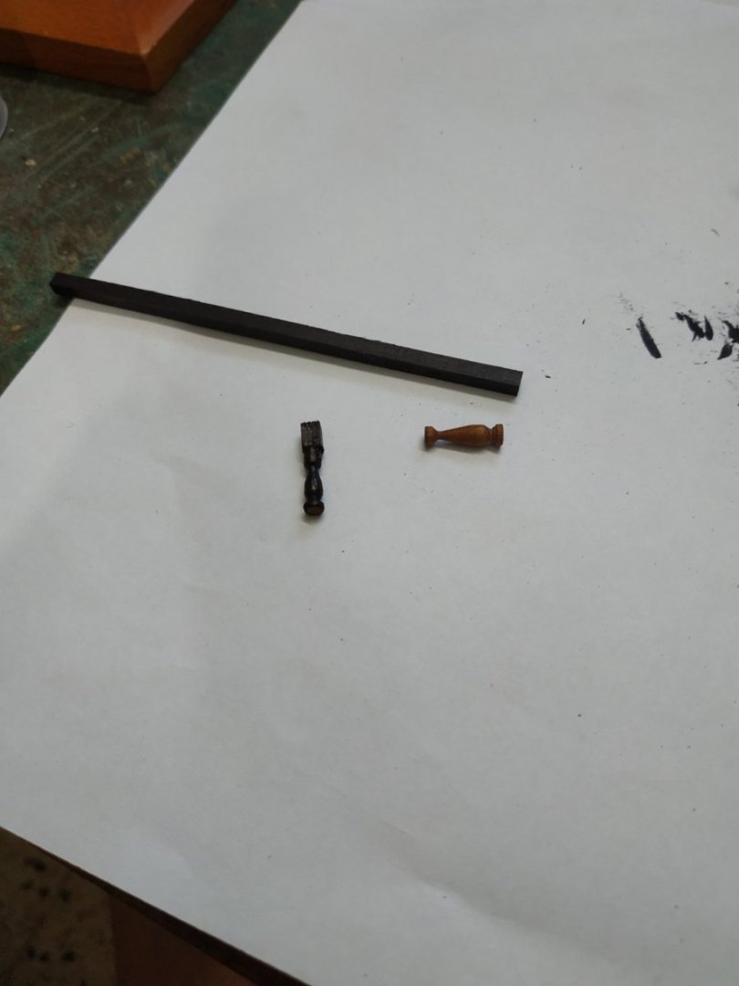
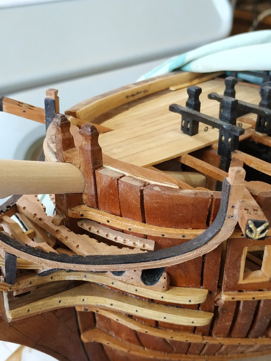
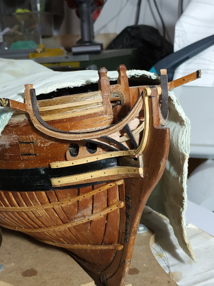
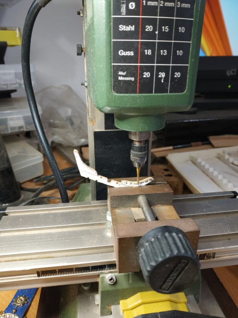
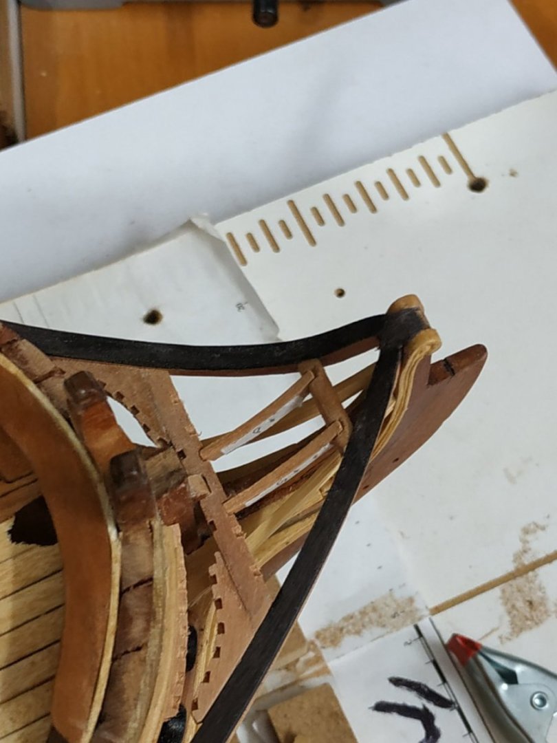
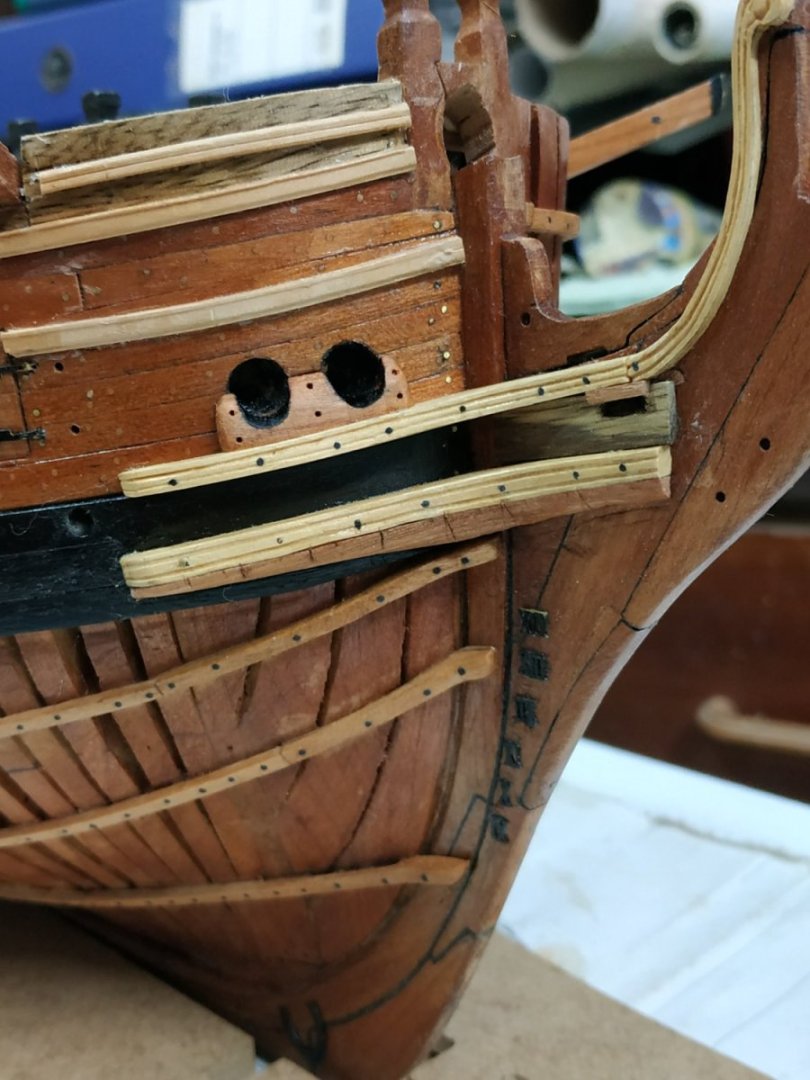
The Saddle for Running Rigging A (less than) semicircular wooden collar sitting slightly forward of the Gammoning Although 3.18mm width and height, a block needs to be bigger because the lower and upper surfaces are beveled to parallel the Bowsprit. A number of holes pass through the collar - variously 4 to 7. I made 7- diam. 0.8mm To angle them correctly, I held the (marked) block in the vice and used a drill press. As suggested by TFFM, bevel the underside and after fixing to the Bowsprit, the upper surface is more easily beveled, as required.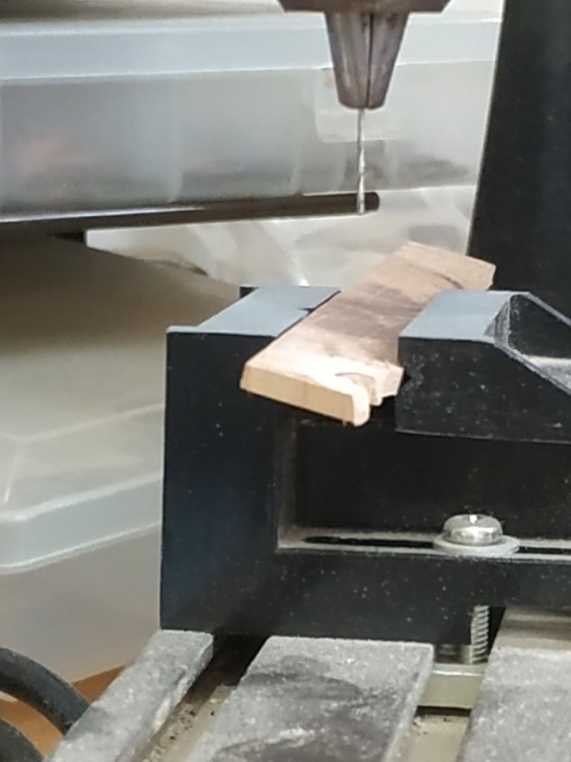
-
Swan-Class Sloop by Stuglo - FINISHED - 1:48
stuglo replied to stuglo's topic in - Build logs for subjects built 1751 - 1800
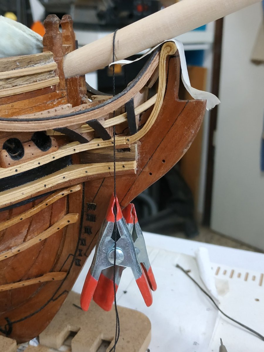
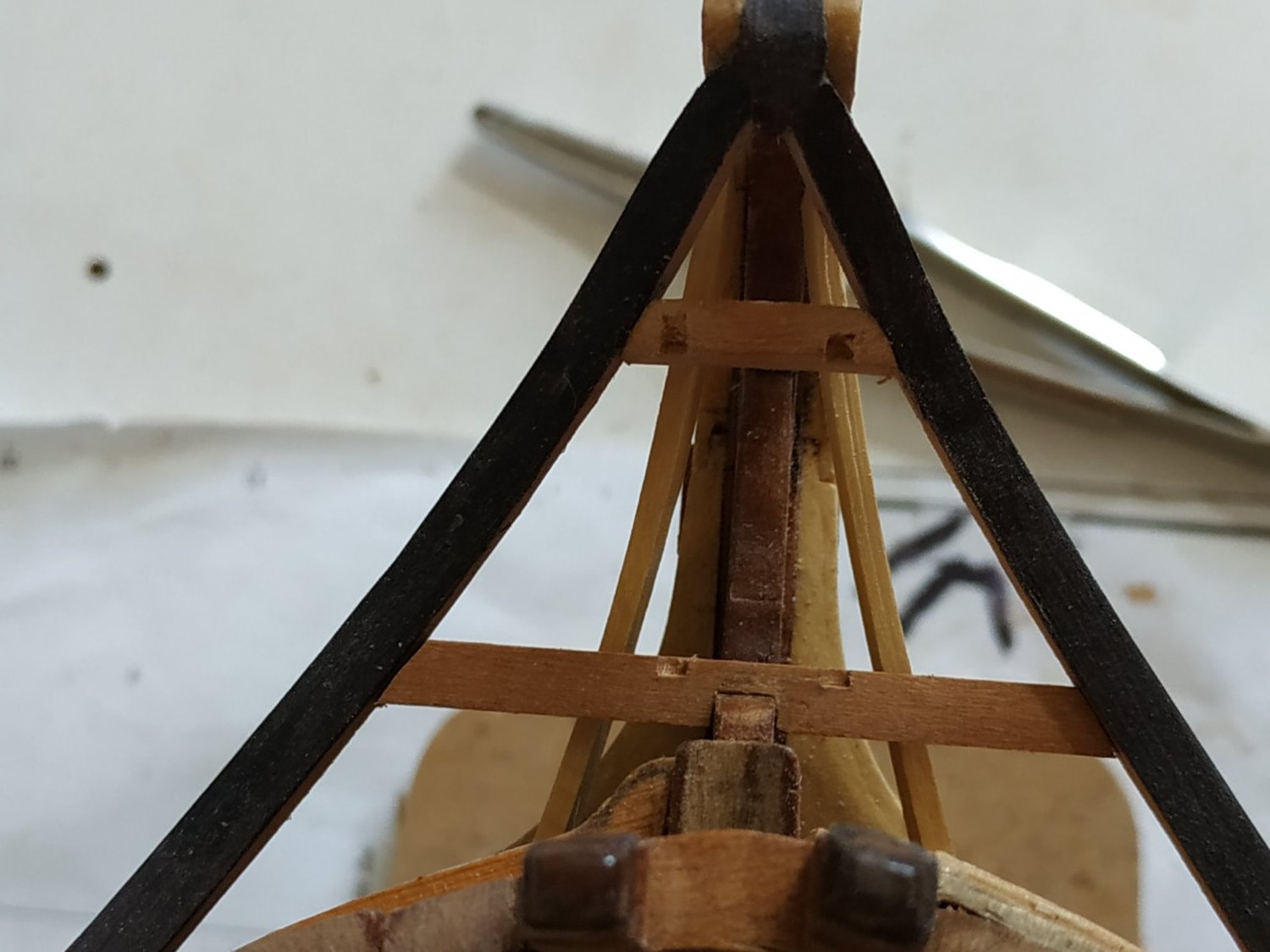
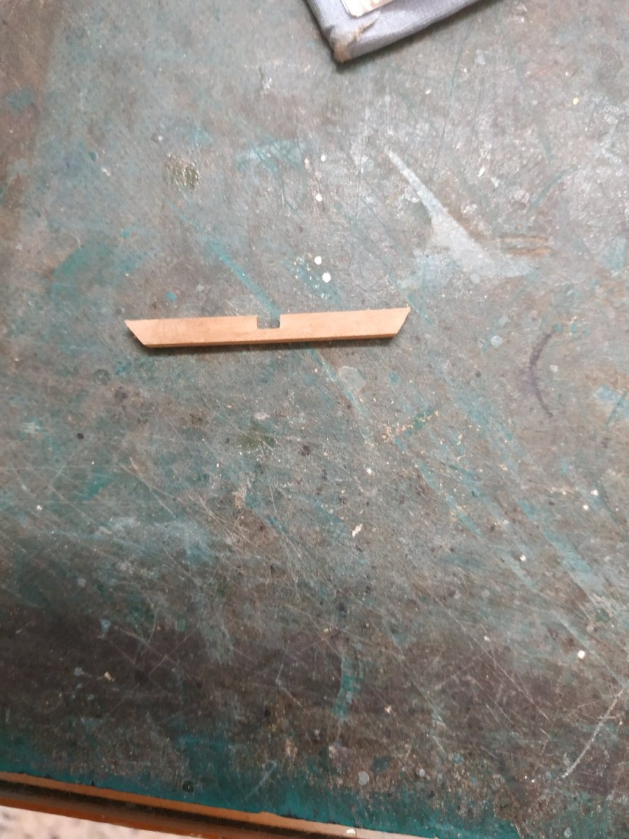
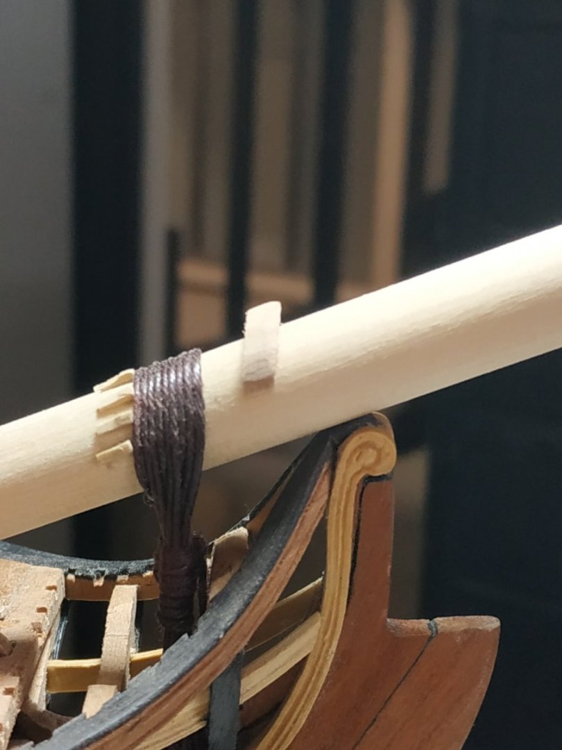
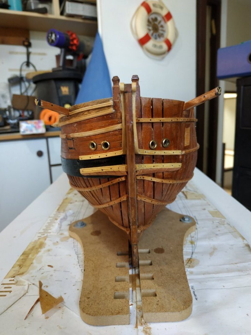
The Gammoning. (note need to read forward to ch.15 TFFM or other reference book) A tired line circumference 2.4 -diameter 0.8mm TFFM suggests starting with 30cms but I found this much too short- I used 100cms. Starting with a (pretend) eye splice, pass the line around the Bowsprit and through the eye so that it hangs to the left. (Elderly gentlemen may recall another significance for this.) Moving through the Slot up against the fore edge, returning over the Bowsprit, against the cleats,the turns are repeated until an EVEN number of turns fills the slit.(My case=8) The descending line is now taken between the upright turns, alternating port and starboard, interspersed with half hitches, for a similar number of turns.The loose end is half hitched through the last 2 turns.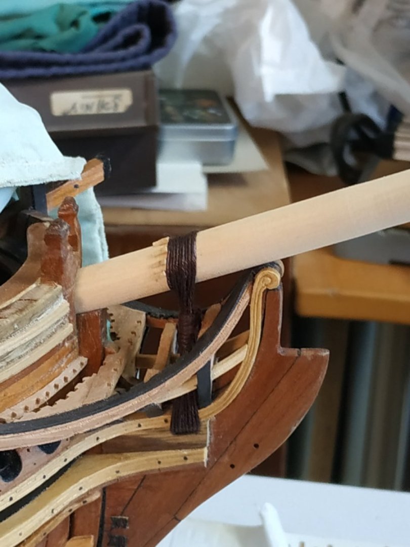
-
Swan-Class Sloop by Stuglo - FINISHED - 1:48
stuglo replied to stuglo's topic in - Build logs for subjects built 1751 - 1800
Decision Time To rig or not to rig- that is the question. Or short symbolic masts, or none. This was supposed to be an “undressed” model-although much remains hidden by the ribs and decks. I intend to make a swan again, but with full planking, minimum internals and fully rigged. Why the opening question? Well, how do I deal with the Bowsprit? Decided short, but enough to show the Gammoning, which is very much part of the Head. Bowsprit. Make it long enough to include the Saddle ,about 15cms A max. Diameter 10.9 mm- narrow forward slightly by 2mm, but aft to 9.35mm before ending in a square 6.5, narrowing to 4.5mm (to fit in the Bowsprit Step). I used lathe and sandpaper strips. Ensure that it fits through the Stem Head and Cross Chock. According to the plans, the Bowsprit rests at 20 deg to the horizontal. By some miracle, the square “heel” fits into the Bowsprit Step. Gammoning Cleats. A line of oblong short strips, 3.7 long and 1.06 sq -slightly wedge shape when viewed from the side. Varied in number between 5 -9 ( I made 7) They are fixed to the Bowsprit so that the fore edges align vertically above the fore edge of the Gammoning Slot. I used a weighted string to mark this line. The outer pair at position 3 and 9 of the clock, the rest evenly spread.

-
Swan-Class Sloop by Stuglo - FINISHED - 1:48
stuglo replied to stuglo's topic in - Build logs for subjects built 1751 - 1800
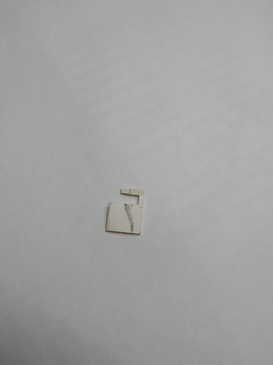
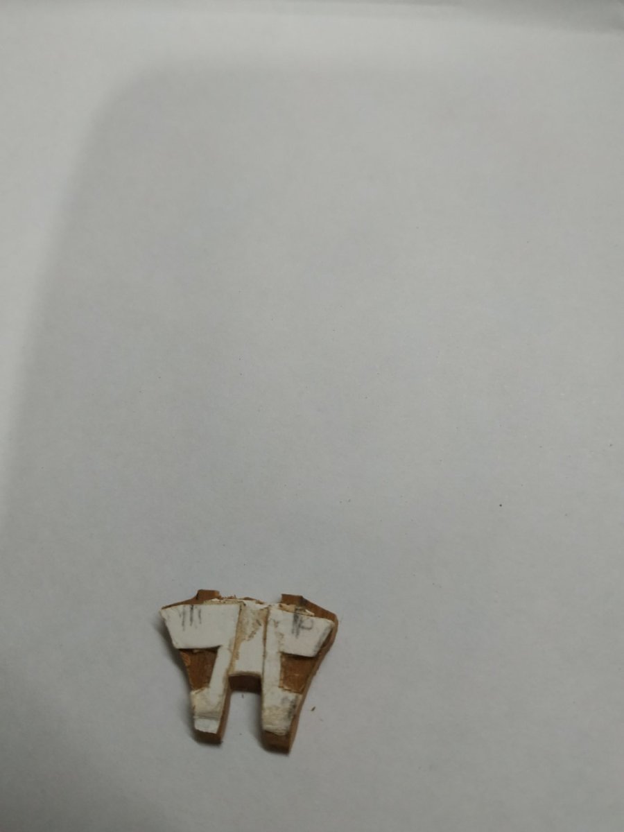
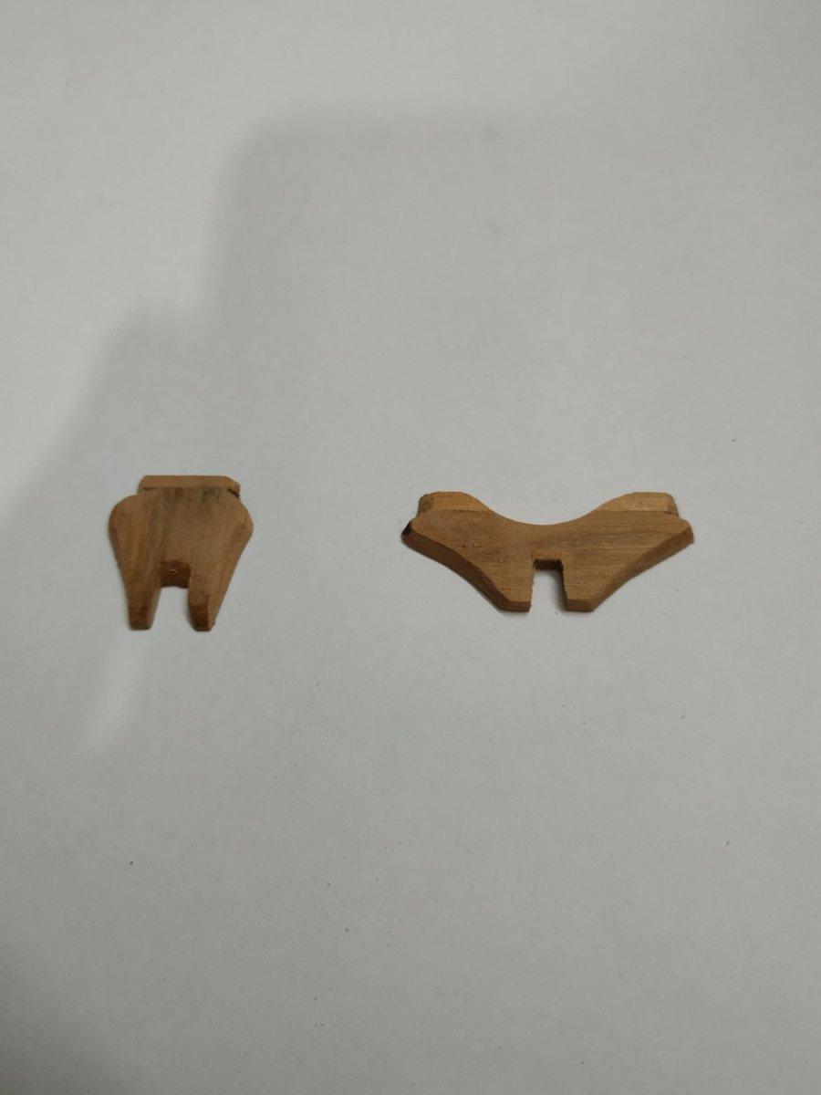
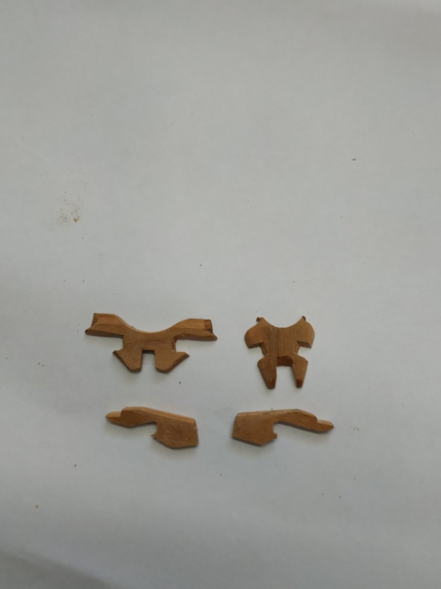
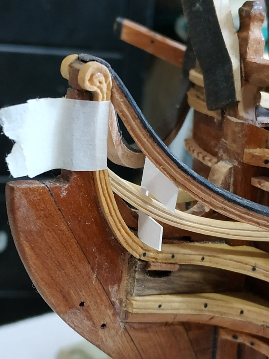
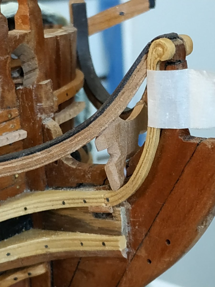
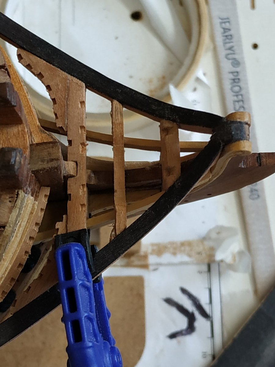
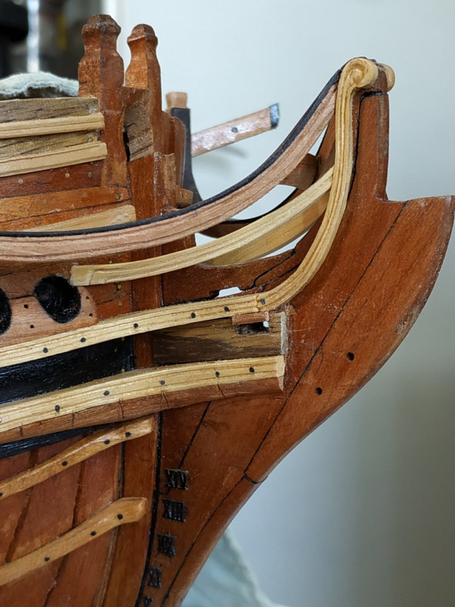
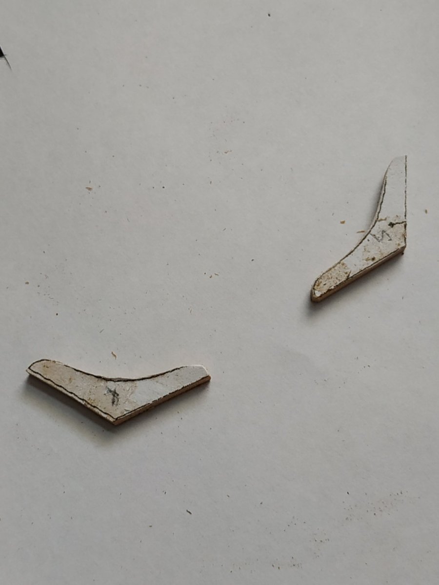
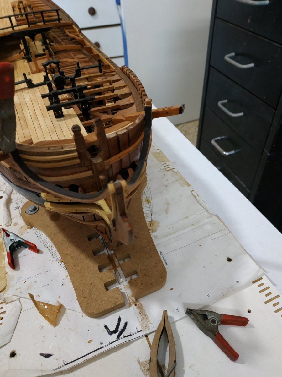
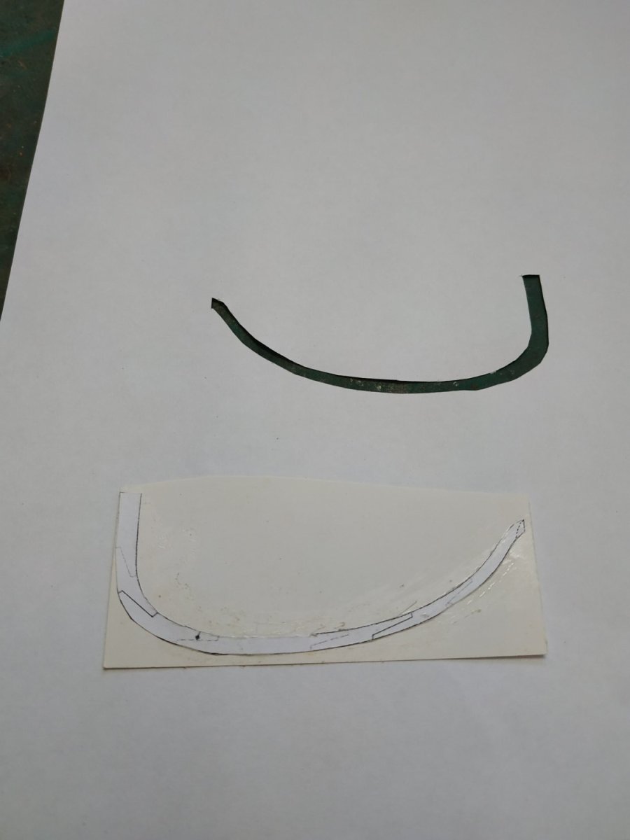
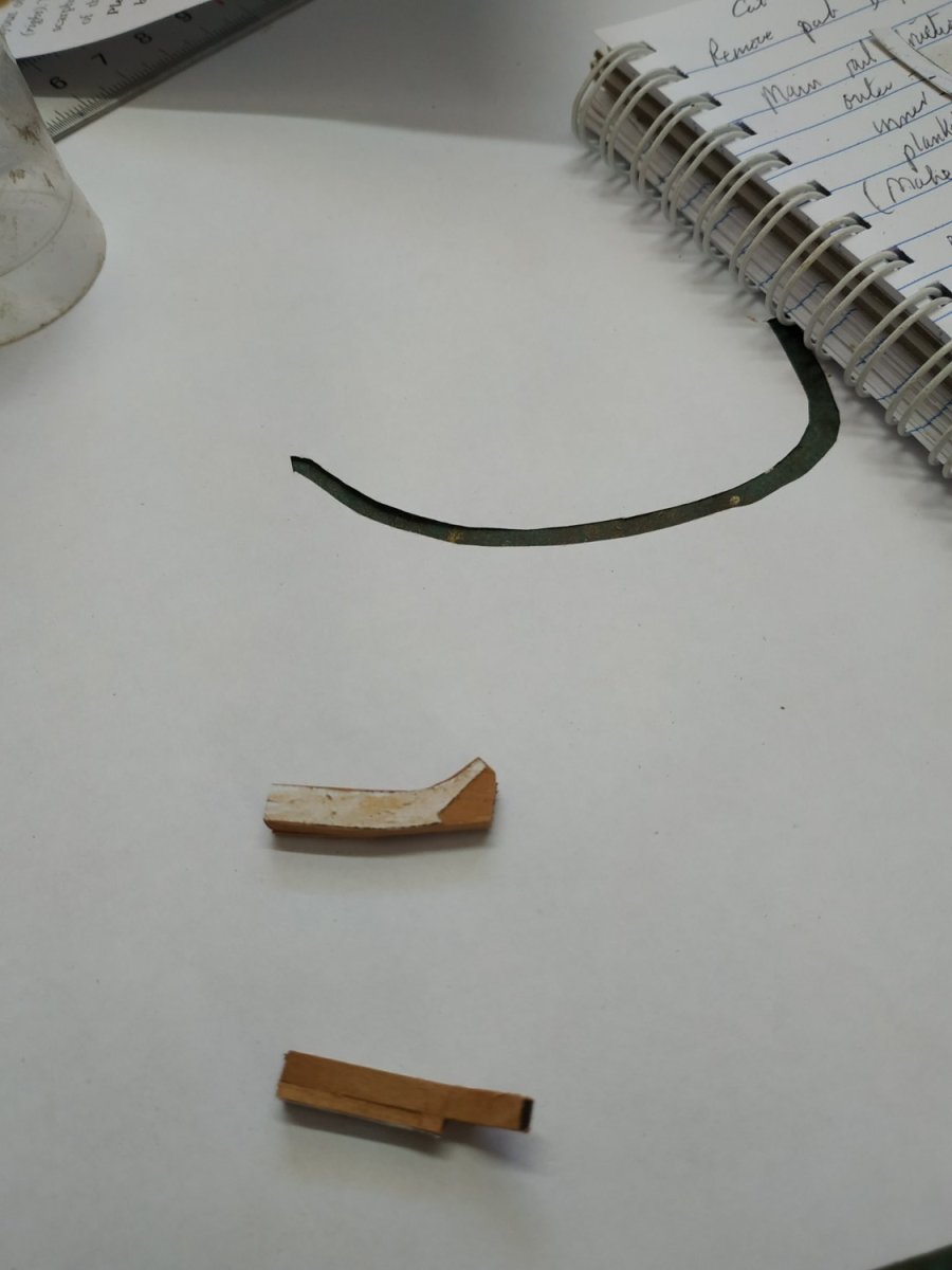
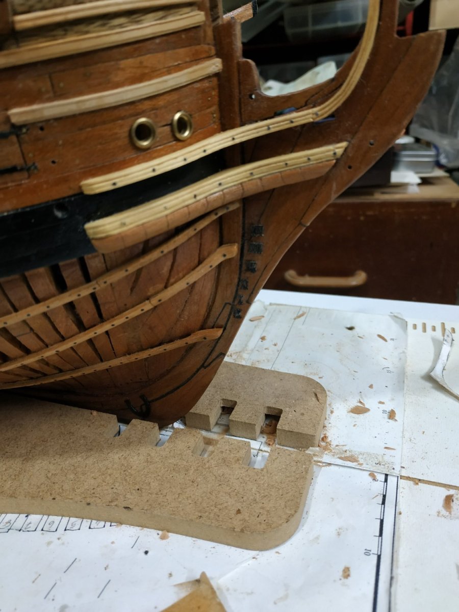
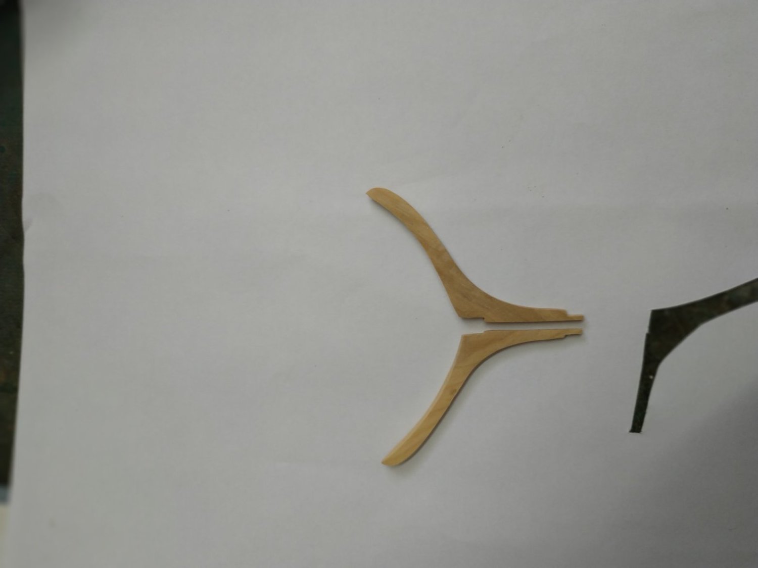
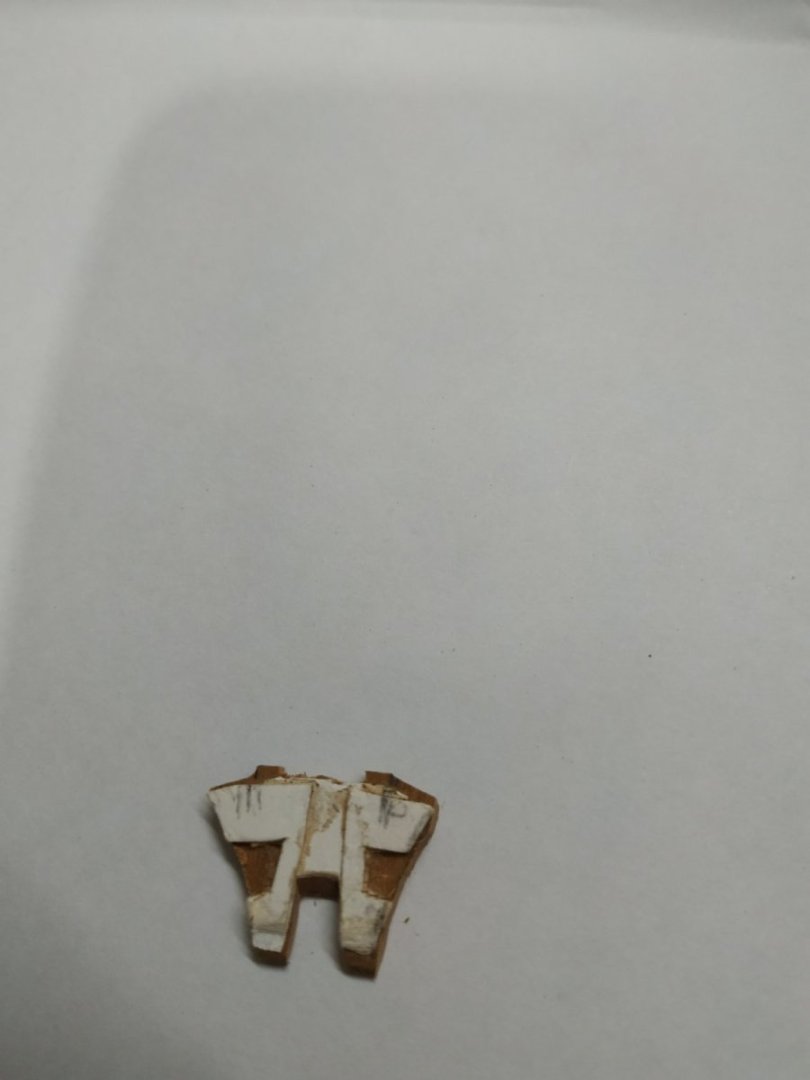
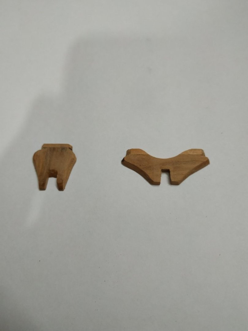
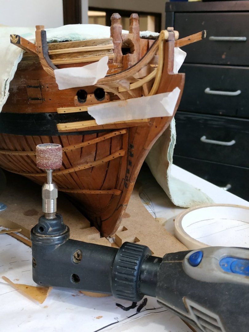
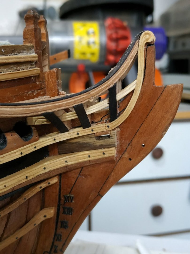
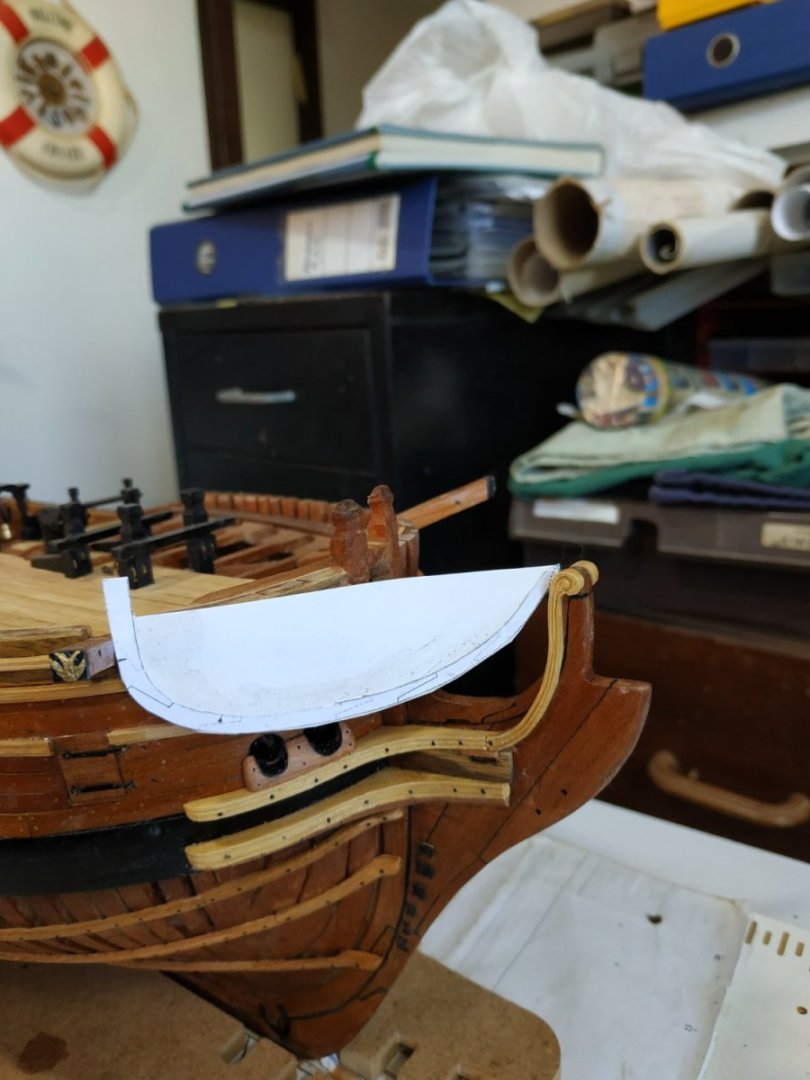
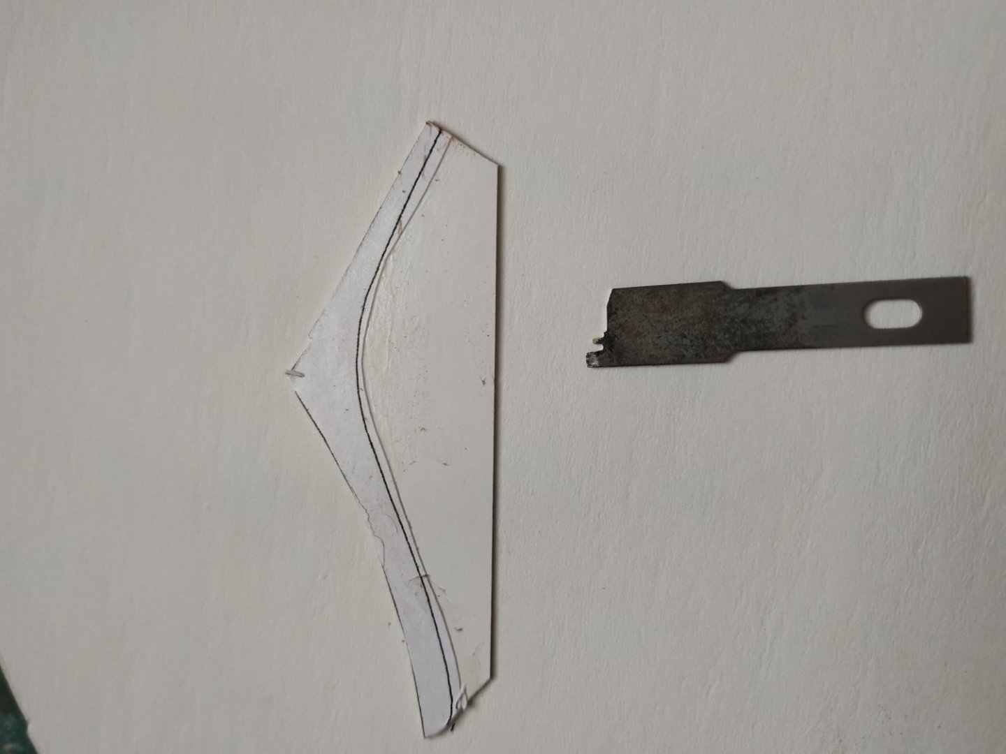
The Head Timbers This is probably the most difficult and complex part of the build so far. No wonder kits either omit or provide the whole as a preformed piece. 3D was helpful in how it should look-but not how to get there. Dan Vardas , usually incredibly helpful, omits much of the process and mentions a problem with a camera. I suspect he threw it out of a sense of frustration. Reliable TFFM was detailed - I just couldn’t understand most of it. (post-covid brain) First decide the model has 3 or 4 Head Timbers- my plans do not show #1 - the aftermost. (thankfully). #2 is below the Head Beam. #4 is above the fore edge of the Trail Board. #3 is between #2 and 4. Their width varied- #2 -2.65mm, #3 2.4mm. #4-1.9mm . Anyway, the drafting advice was beyond me at my best. It suggested as an alternative a CARD method. which I adapted. Firstly remove the Carlings,Beam, and Crosspiece- I decided to leave the Main Rail in position, however. Starting with #4 A piece of card is cut to the height between the upper cheek and main rail, and depth from the outer edge of the main rail to the Knee of the Head, at position of the aft (larger in this case) surface. The Lower Rail is still in place, and its position marked on the card. A slot is cut at this level. It was seen that my Lower Rail was too high on the Hair Bracket and was adjusted to sit lower, The new position and slot adjusted to the card. This is repeated for Timbers #3 and #2. The Lower Rail is removed and each card is held in place so that the depth of the slot can be adjusted so the Lower rail can fit into its position. This is repeated for the other side of the head. A bridging piece is needed so as to include the width of the Extension piece of the Head for #4 and #3 (#2 sits either side and therefore aren’t joined). The aforementioned difficulties are now apparent. The various and varying angles particularly with the Main Rail need addressing. TFFM gives a way of marking the various angles with additional slips of card, but this didn;t work for me. I went straight to a blank, roughly shaped to the card, and then by trial and error fitted into position. Then fashion the slot for the Lower Rail. Note that, because of the acute curve of the Extension and Main Rail, slight change of position has a huge effect on the fit. Temporary gluing in place and releasing with alcohol is required (Unlike TFFM, I found photo glue not suitable) Note also to shape upper surfaces to allow fitting of the Beam and Cross Beam. The Outer surface (with its angle following the Main Rail ) can now be roughed out, It was found that the slot allowing the Lower Tail, requires “closing” and some additional wood was added. A final shaping of this surface requires some care, with protecting the Rails. VERY careful use of the sanding drum and the same drum, handheld, did the job. This surface is covered by a Covering Board, 0.53 mm in thickness. It is supposed to be paneled, but I made the whole from my black hornbeam wood. To enable this to be fitted, the outer surface of the Timbers are cut back by 0.53mm, so that this Board is flush with the outer edge of the Main Rail above and the Upper Cheek below. PHEW !!!!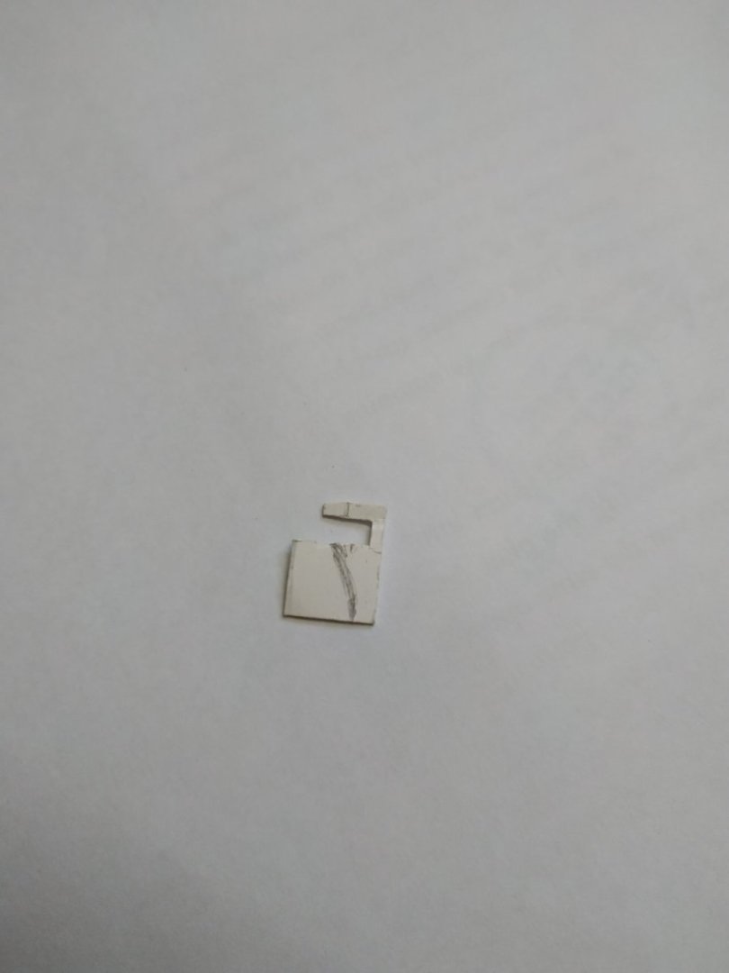


- 475 replies
-
- 13
-

-
Seats of Ease
stuglo replied to stuglo's topic in Discussion for a Ship's Deck Furniture, Guns, boats and other Fittings
After a quick read, this must be the definitive work on the subject. Just note the "poop" deck, is derived from the Latin/French, stern or rear - poop meaning excrement presumable derives from this. -
Not sure if they fall into the category of furniture or fittings, but always of interest (with a smile) rather like a child's toilet joke. But were they really used as such? Imagine 2 or 4 seats for a 100 + ordinary sailors. Imagine making your way forward in the dark over the fore planksheer, over the gratings, shifting or wallowing ship beneath your feet etc not forgetting the soaking from sea spray. Just imagine the frequency of intestinal disease and disorders likely at sea and tell me how these could possibly "ease" the problems. Methinks they just eased the conscience of Milords of the Admiralty
-
Swan-Class Sloop by Stuglo - FINISHED - 1:48
stuglo replied to stuglo's topic in - Build logs for subjects built 1751 - 1800
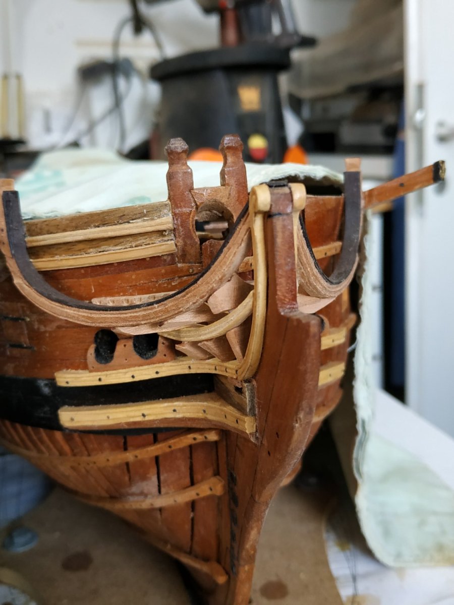
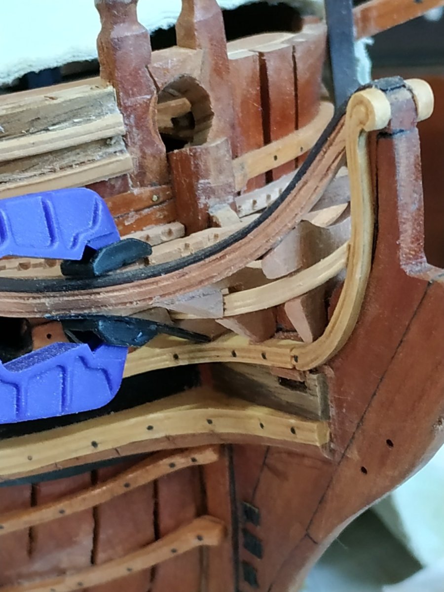
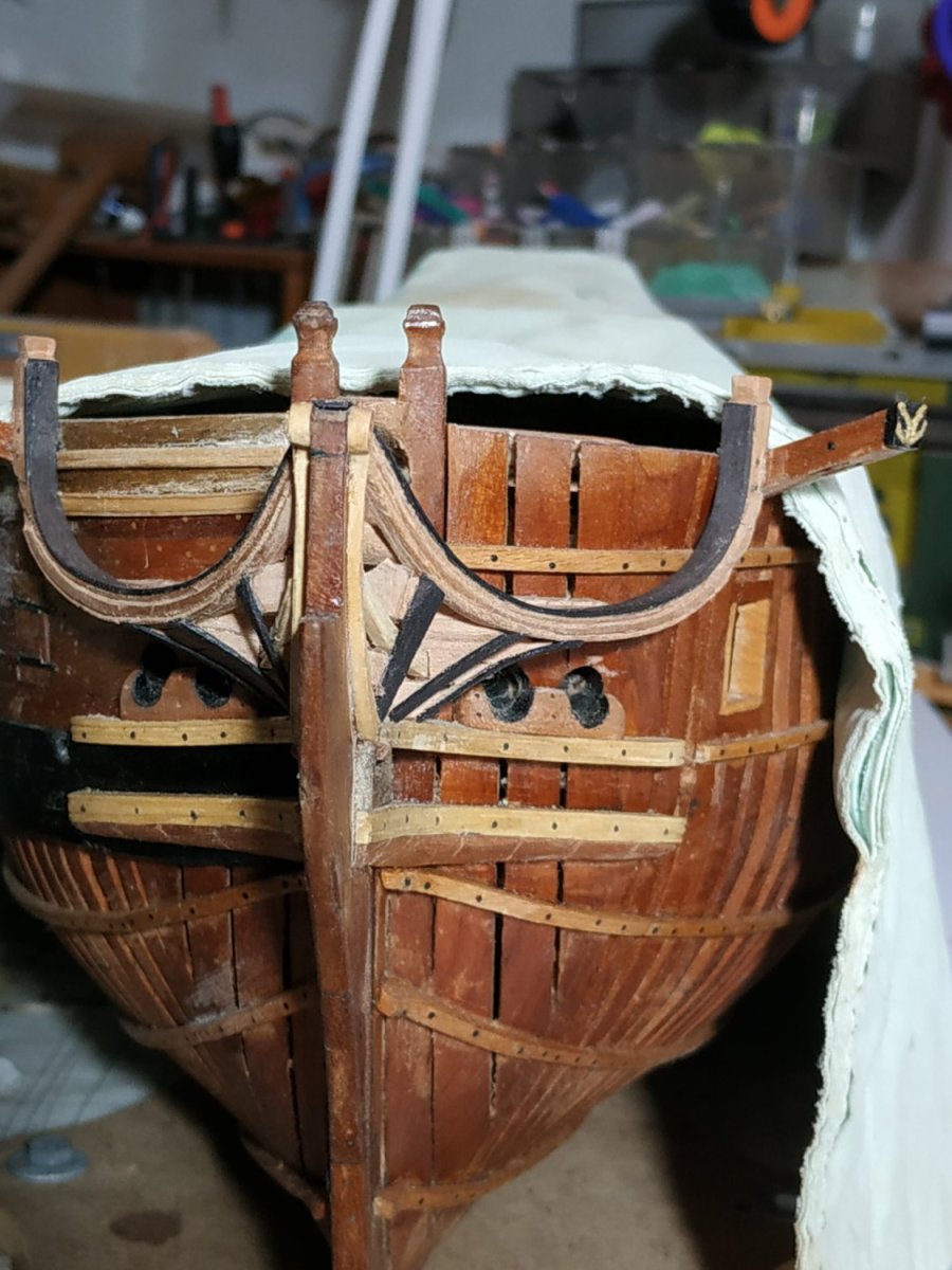
Preparation for the Head Gratings A series of ledges which form the surface of the head. 1.6mm wide, the section shape changes with their position. The Batten. Runs round the Bow, the upper surface level with the Head Beam and Knees. They are 2.1mm deep and 1.6mm wide ( as I did not plank the port hull, this thickness is added to the portside width). The position of the forward sections of the Waist, Sheer and Drift Rails need slightly altering and are removed. (The patterns in TFFM show starboard different to port- to allow the optional fitting of an aft pair of seats of ease. I will not fit these.) The Battens, Beam and Knees are removed so the mortises for the Ledges can be milled. (Ledges 1.6mm wide). These form a “fan”shape, and off model their position and angle can be matched. The Battens are now fixed, Beam,Cross Piece, Carlings are temporarily removed.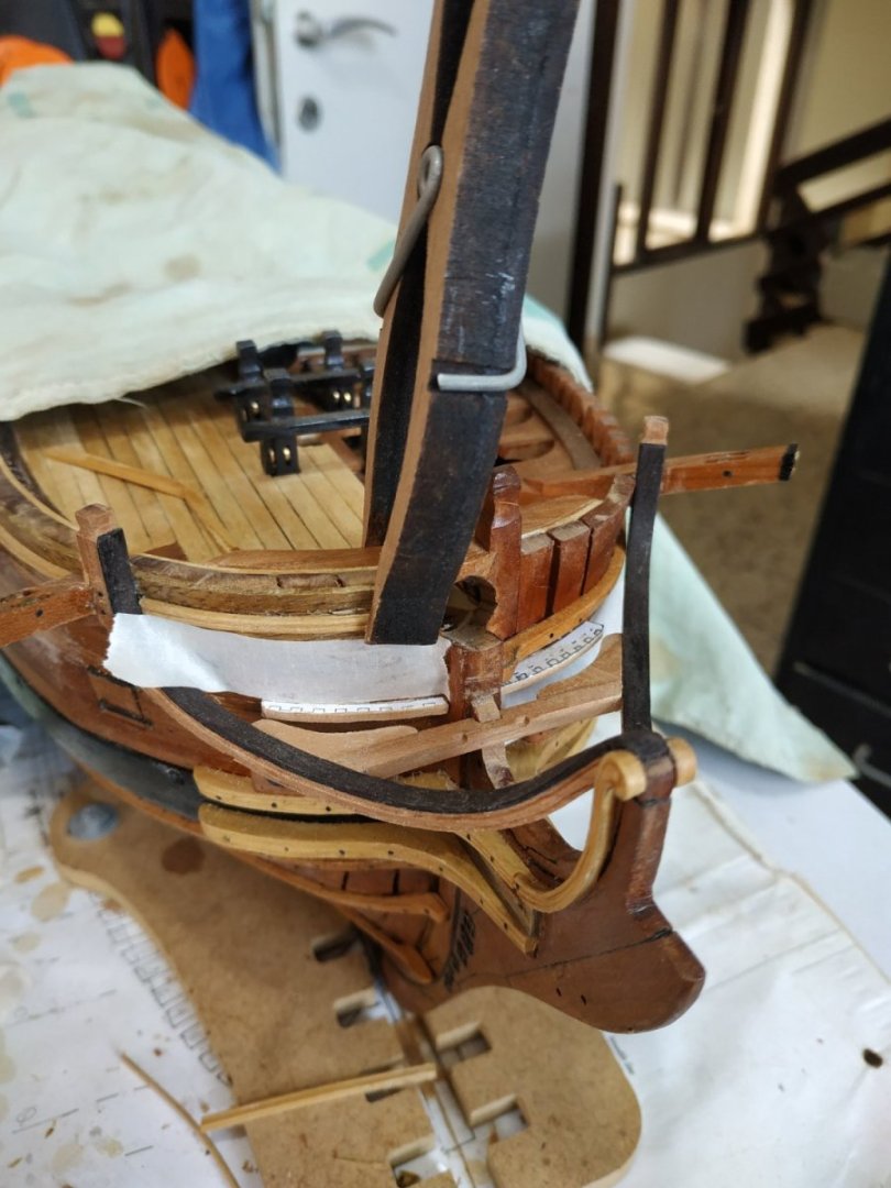

-
Swan-Class Sloop by Stuglo - FINISHED - 1:48
stuglo replied to stuglo's topic in - Build logs for subjects built 1751 - 1800
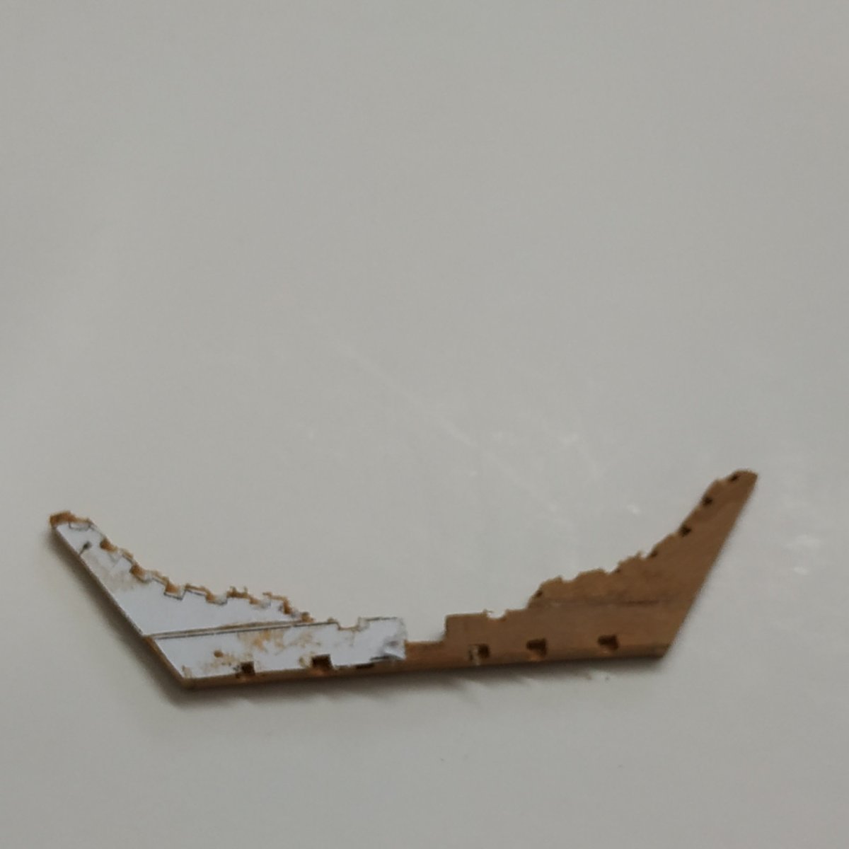
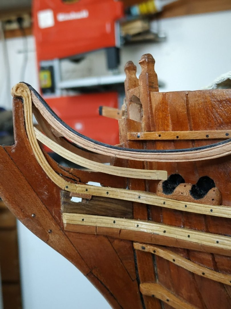
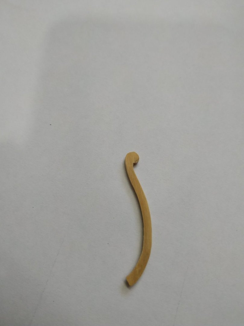
Lower Rail of the Head Rests aft on the inner “arm” of the Hawse Bolster, and fore , the rising Hair Bracket. The width (from above) is 1.9mm aft narrowing to 1.5mm fore. Depth, 3mm to 2.4. The molding starts a few mm before the aft end. The points of contact with the Hull Requires shaping for the acute, curved angle. *This rail as pictured is too high on the Hair Bracket, but in any case will be removed and replaced a number of times to allow the further building of the Head.

-
Swan-Class Sloop by Stuglo - FINISHED - 1:48
stuglo replied to stuglo's topic in - Build logs for subjects built 1751 - 1800
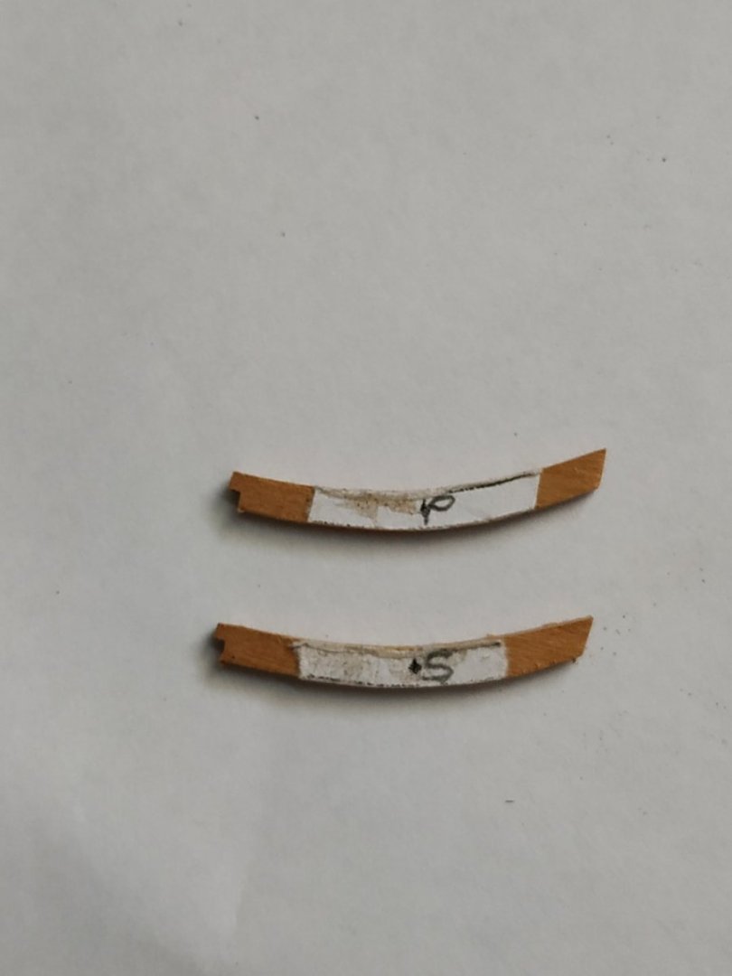
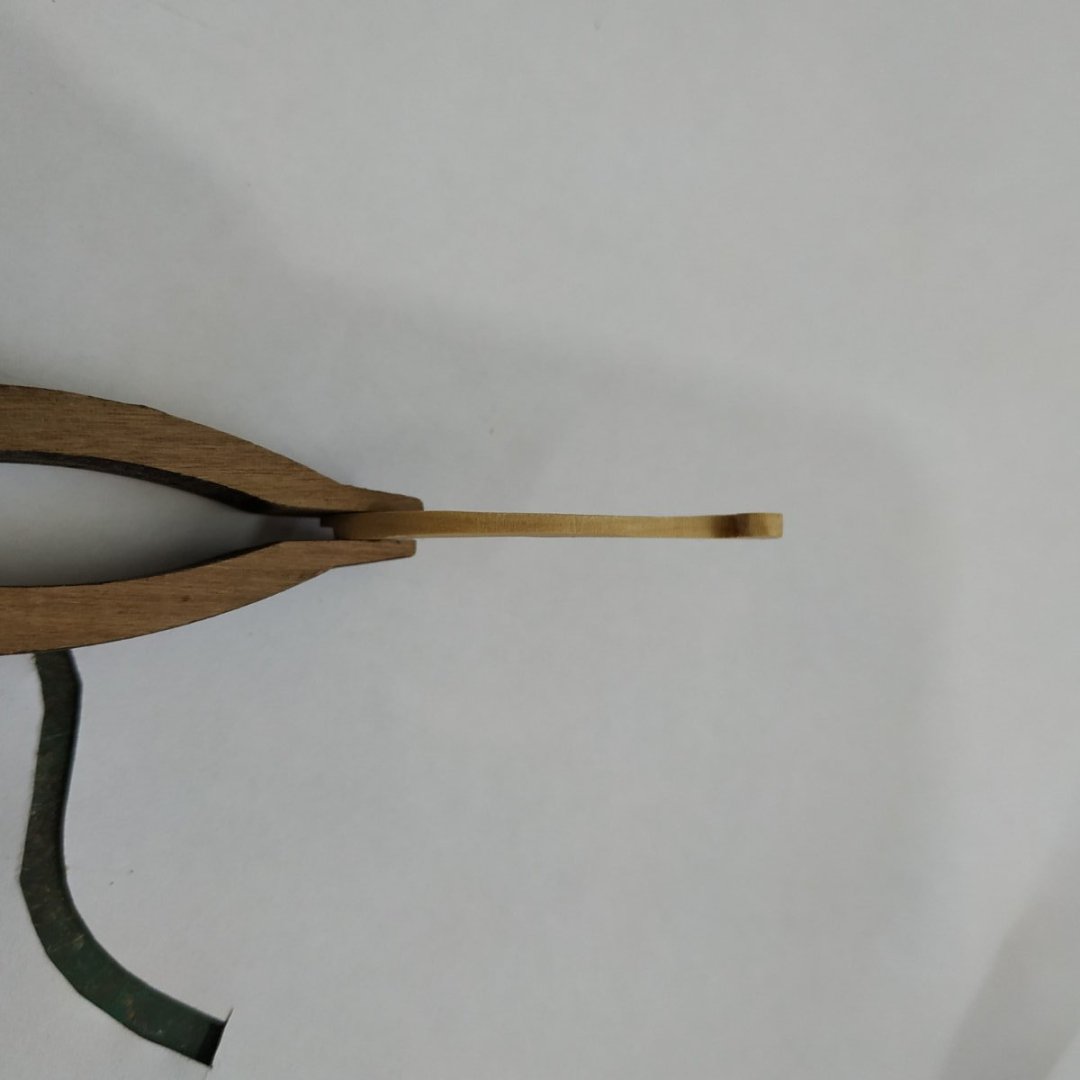
. Head Carlings These are a pair of fore-aft members used for the support of the Head Gratings. They are let into the Head Beam and Crosspiece. They are 1.6mm (from above) and 2.12mm deep. They follow the curve of the Main Rail BUT from the SHEER plan (not the expanded view) They separated to allow the Gammoning to pass between them. The mortices in the Head Beam and Crosspiece are milled off-model . I now realised that the Head Beam should be set further aft- the upright of the Standard is too wide and therefore sanded back. The Carlings will be remade, longer, to fit the new position, when the Head Beam and Crosspiece are permanently fixed in position.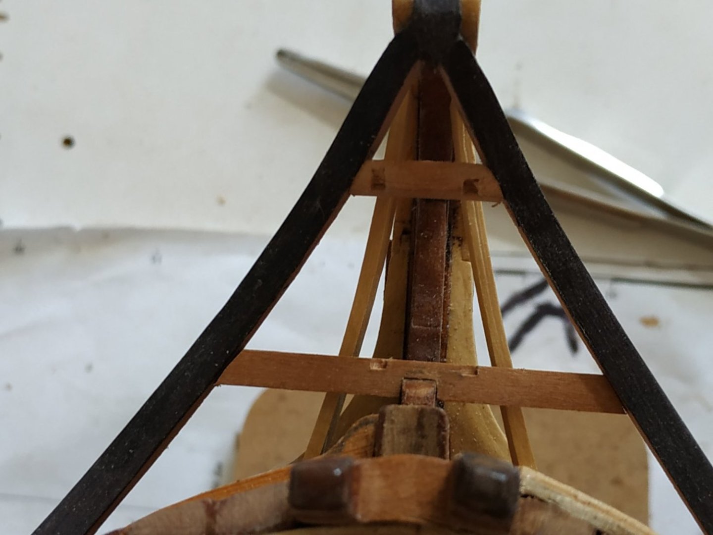
-
Swan-Class Sloop by Stuglo - FINISHED - 1:48
stuglo replied to stuglo's topic in - Build logs for subjects built 1751 - 1800
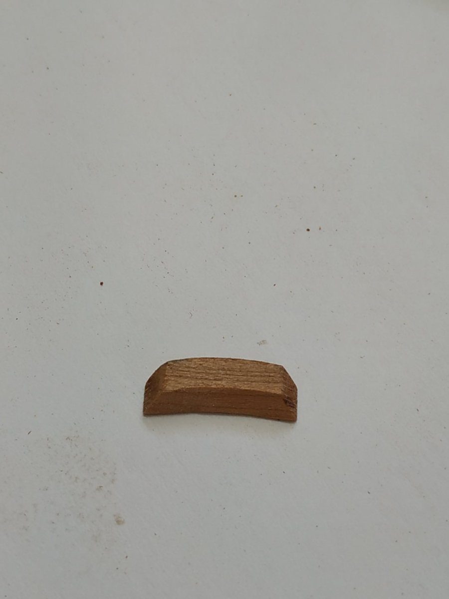
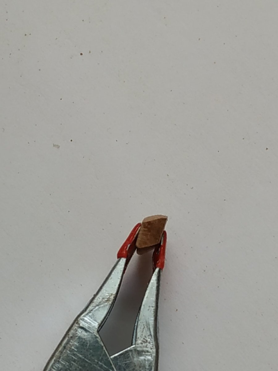
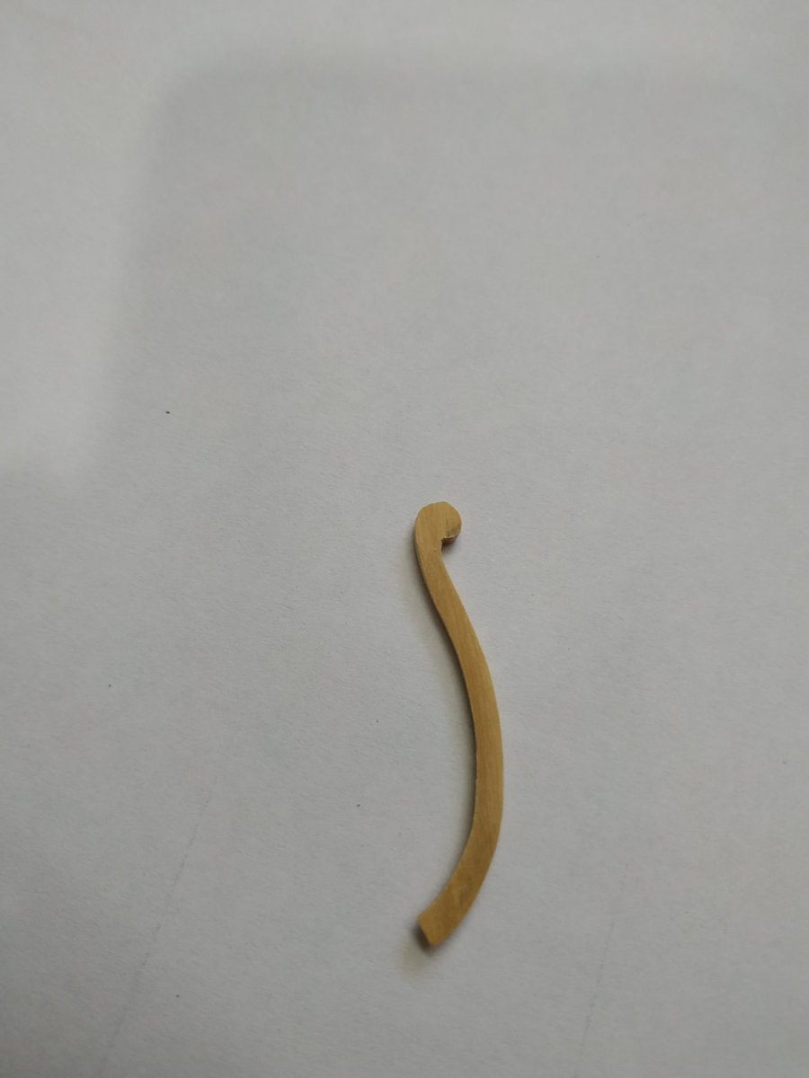
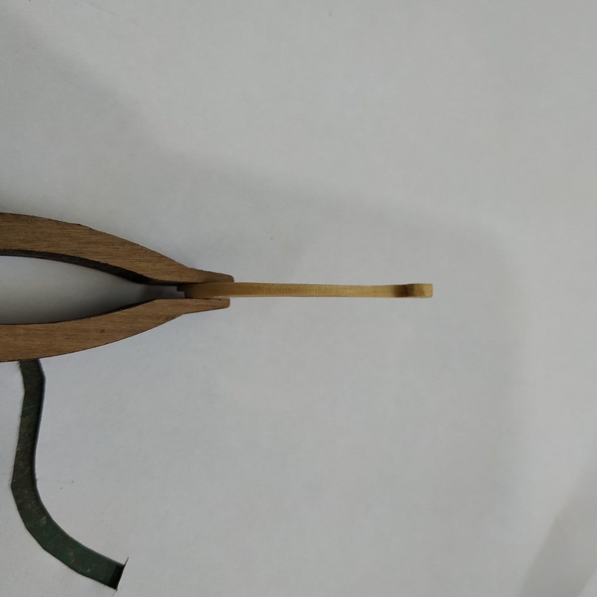
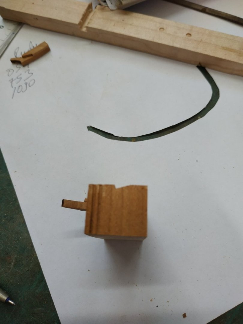
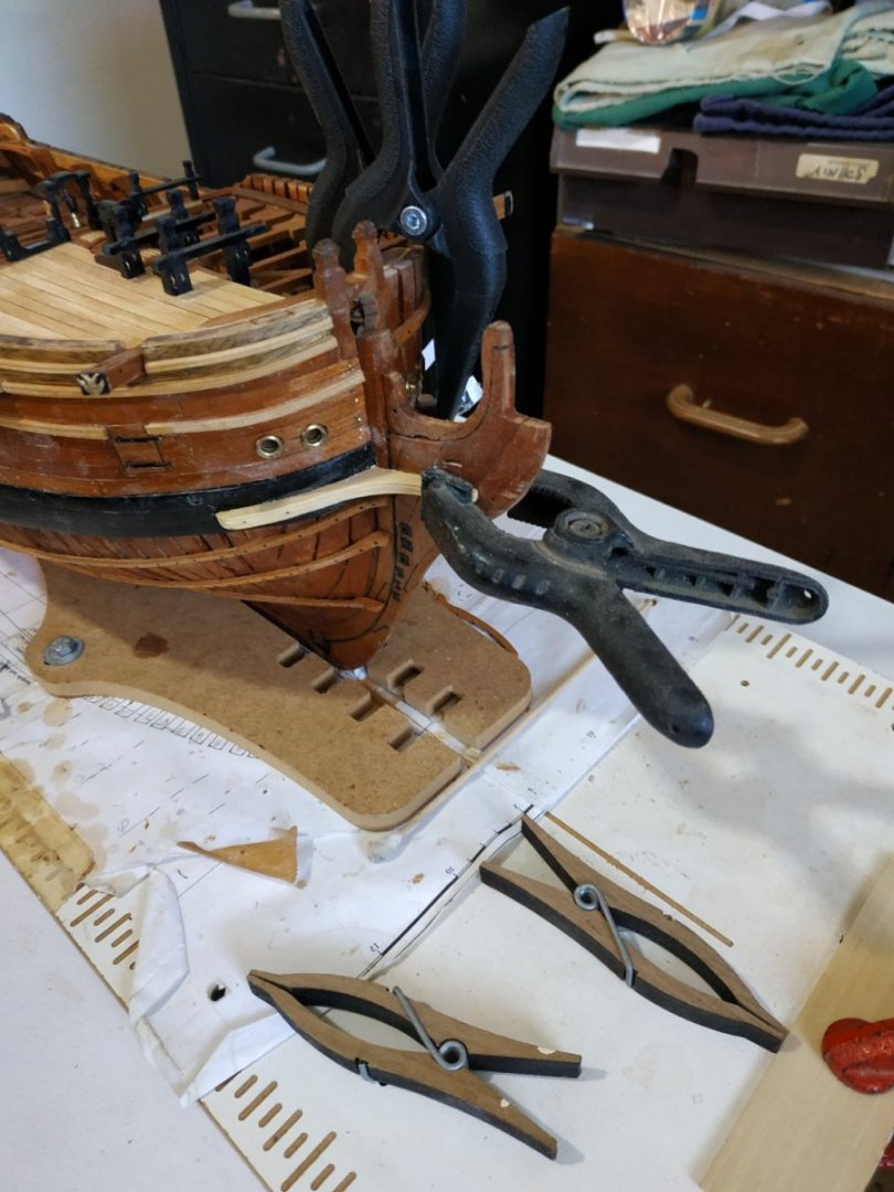
#414 should be titled - Cross Piece of the Head (A really fiddly little bit to make) Positioned with 4th Head Timber above the fore edge of the Trail Board, between the Main Rails. It performs a similar function to the Head Beam. It is 1.6mm wide, with a rhomboidal section. Similar rounding up 0.8mm, the upper and lower surfaces beveled to follow the curve of the Main Rail. I started with a block 6.6 deep to allow for the various curves. The ends are angled acutely to fit between the Main Rail. Again not permanently fixed.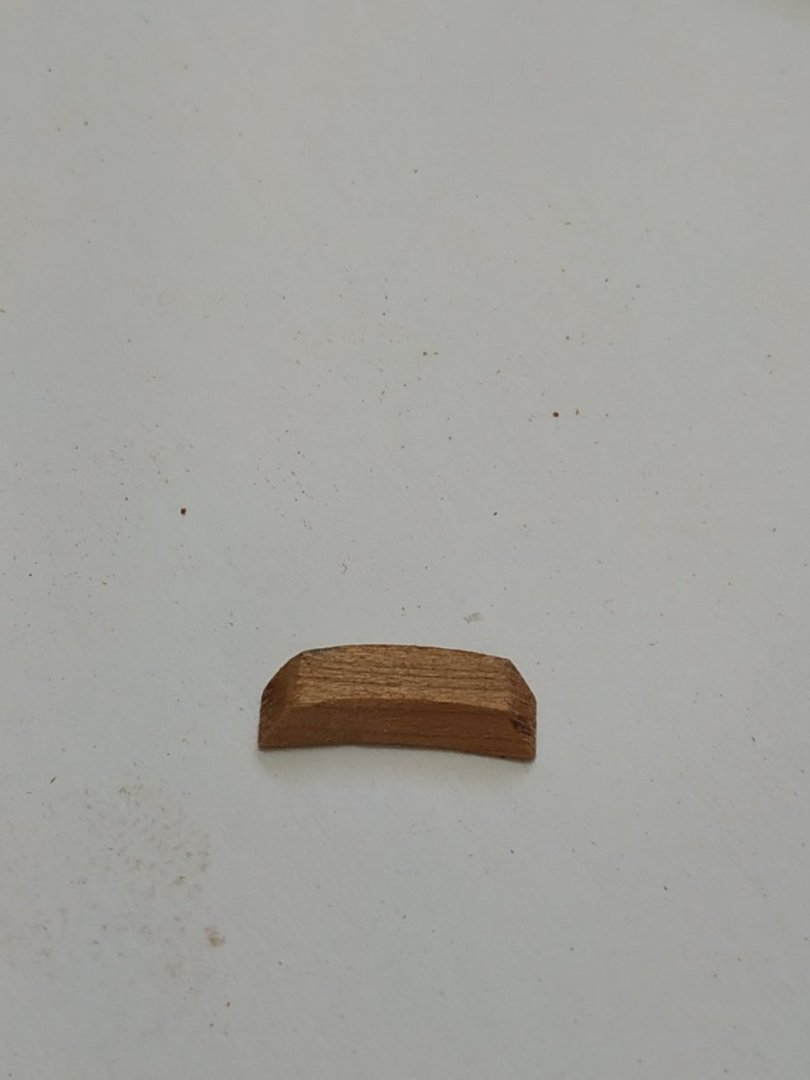


-
Swan-Class Sloop by Stuglo - FINISHED - 1:48
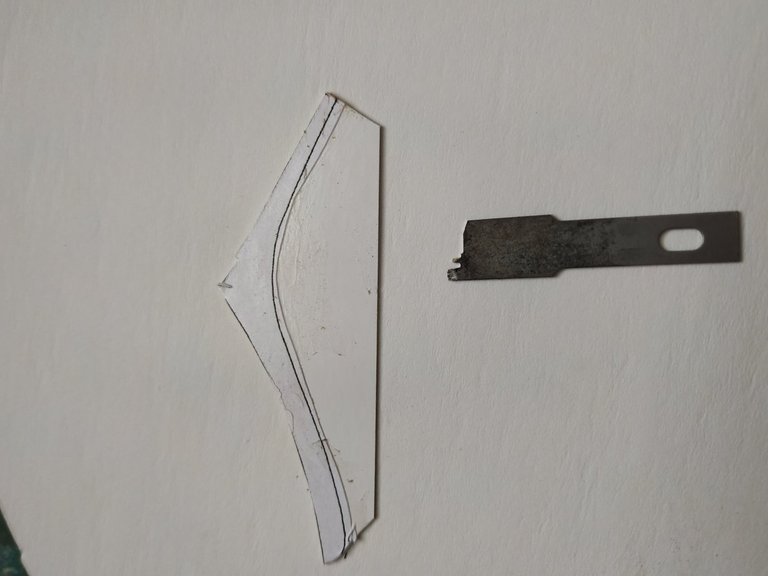
stuglo replied to stuglo's topic in - Build logs for subjects built 1751 - 1800
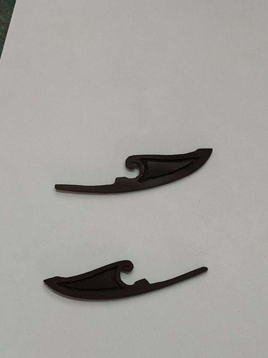
The False Rail Shaped board-like structure fixed to the curve of the Main Rail Inboard flat, outboard paneled effect.The inner face flush with the Main Rail Lining. Thickness, 2.12 mm with groove recess 0.53 I didn’t feel able to make this recess at a constant depth, so I made a composite of 3 pieces: Base of 1.6mm, a surround of 0.53mm and an insert of 0.53mm (the Hornbeam blackwood is brittle and cutting part cross-grain caused the need for some repair after it was stuck to its base)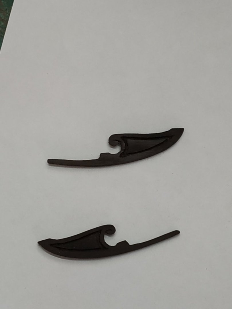
-
Swan-Class Sloop by Stuglo - FINISHED - 1:48
stuglo replied to stuglo's topic in - Build logs for subjects built 1751 - 1800
Head Beam Runs athwartship and ties the Head Rails together. Sided 3.98mm deep 2.9mm. In section parallelogram. Rounded up by 0.8mm. Half-jointed to the Standard (of stem), which is curved - the mortice adjusted for this. (of course, after making this perfectly, I realised it was upside down instead of upper surface convex. CHECK EVERYTHING TWICE). Do not fix it permanently yet. Knees Reinforces corner of Beam and Main Rail Sided 2.12mm. Arms 14.3 Do not fix it permanently yet.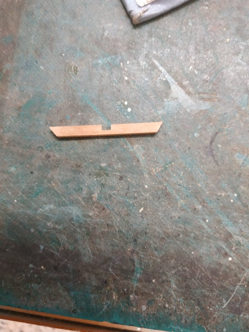

-
Swan-Class Sloop by Stuglo - FINISHED - 1:48
stuglo replied to stuglo's topic in - Build logs for subjects built 1751 - 1800
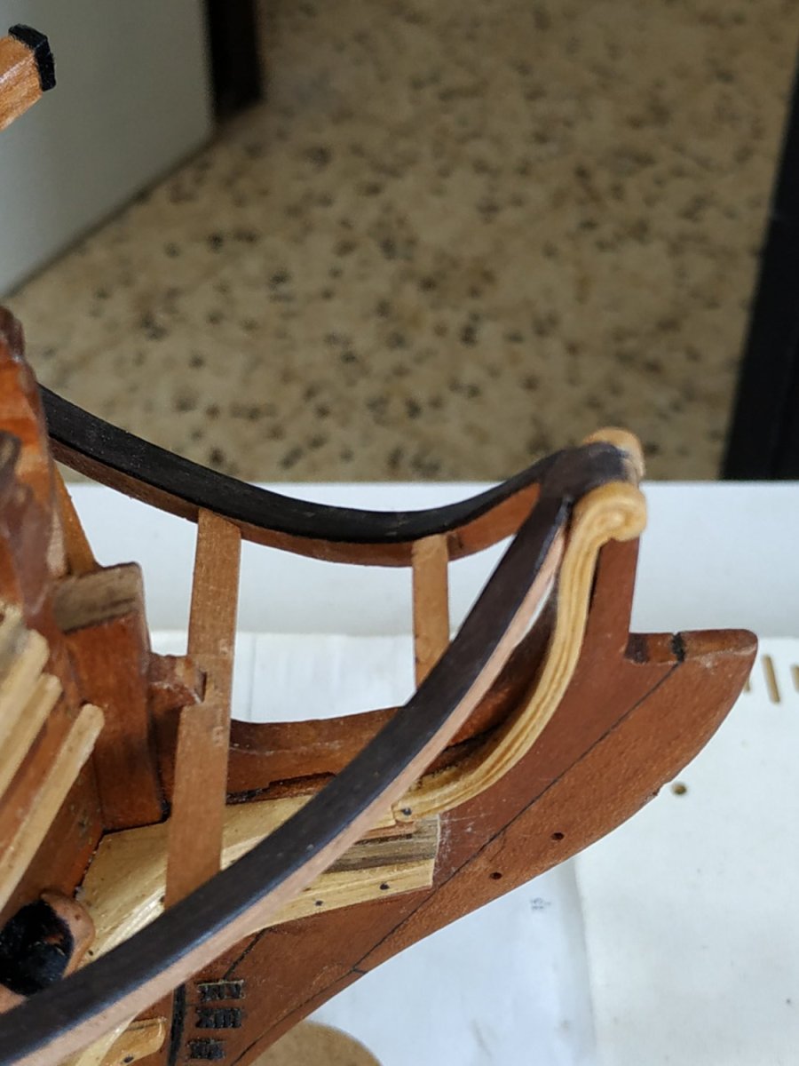
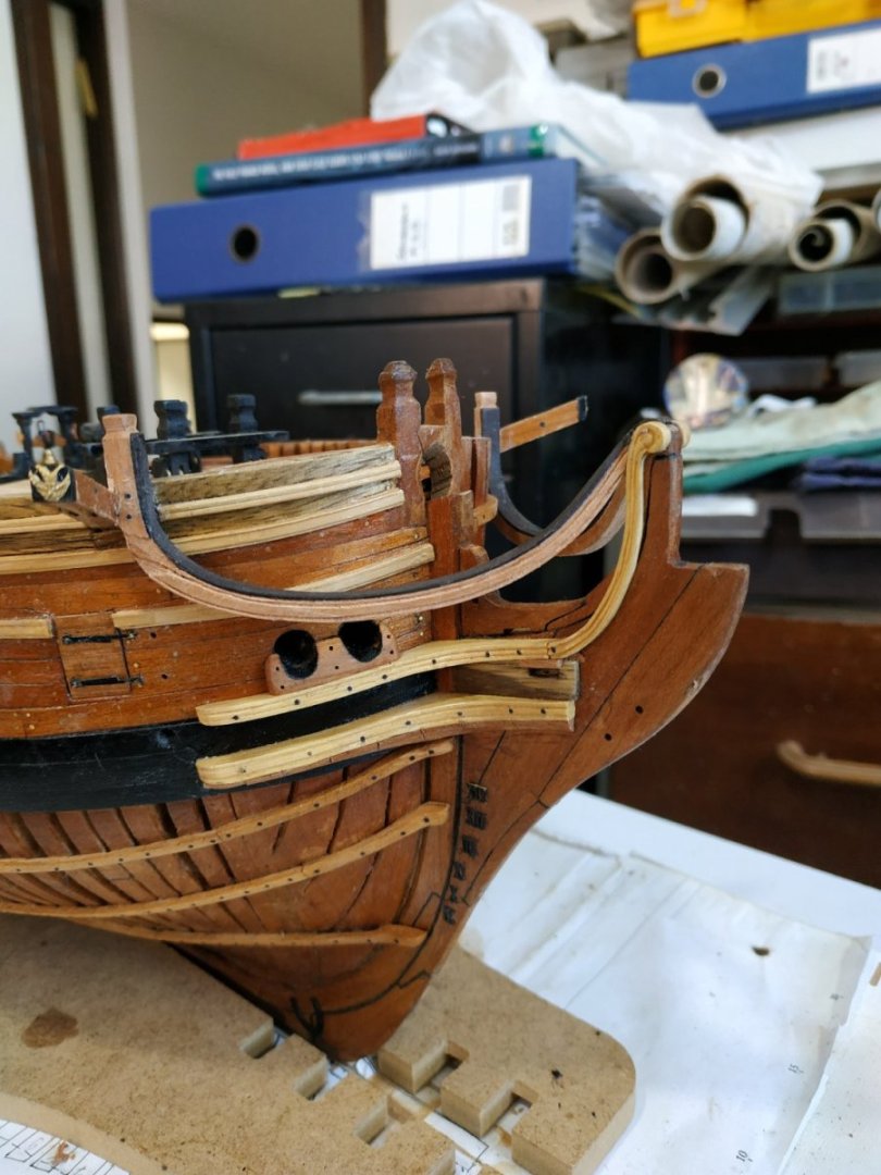
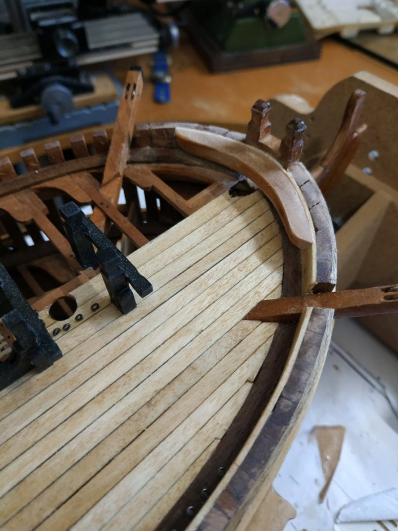
Molding of the Main Rail Below the level of the Carhead are 2 “step downs” The 1st thins the Rail by 0.53mm- upper and lower limiting lines supposed to be “S” shaped-easier said than done. The next step meets the depth of the groove of the molding. The outer face of the Rail is beveled to half thickness at lower edge to simplify the scrapping. I had no readymade scrappers to match the patterns suggested- in any case I made a fundamental error in using cherry instead of boxwood-the cherry doesn’t take to scrapping and the end result was not satisfactory. TFFM suggests the possibility of extra run of molding, but I wanted a contrast and used a separate planksheer. Even though this is only 0.53mm, the blackhorn is brittle, so I used hot water and a bending jig. A thin overlap outwards and the inner side is trimmed to match the inner edge of the lining rail. Scoring for the Cathead, a triangular section groove so that the top of the Timberhead is 9.5mm above the Toptimber Line.(Some of the hull molding e.g. sheer, needs cutting away. The assembly can be fitted so the whole is in a vertical plane, and the Timberhead is also vertical.Also check for symmetry of the curves when eyeballing from the stem.( Not so easy as the wales and moldings are on one side only on my model.) The foremost end is shaped to fit behind the Hair Bracket. When all seems set, I’m left with a small gap between these ends. There is a bolster to be fitted later, to finish this off. I fitted it now so I won’t see the error which otherwise would annoy me and force me to scrap the lot and start again !.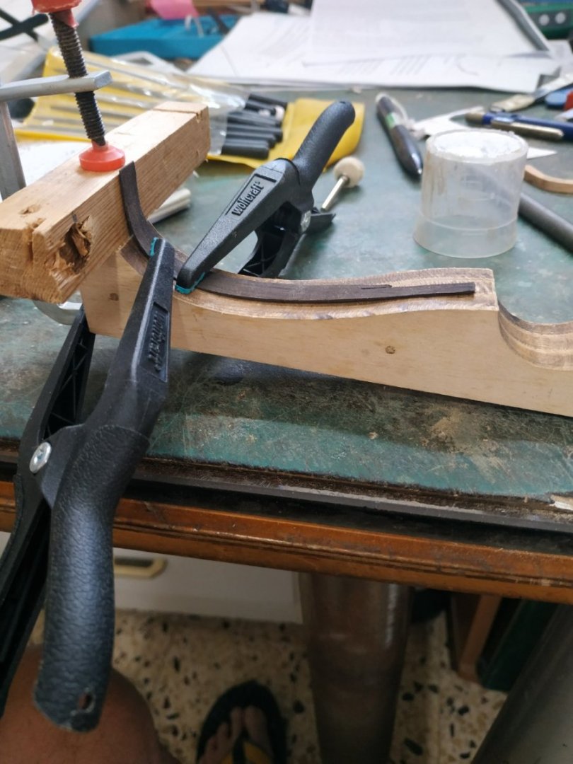


- 475 replies
-
- 10
-
-

-
Swan-Class Sloop by Stuglo - FINISHED - 1:48
stuglo replied to stuglo's topic in - Build logs for subjects built 1751 - 1800
Main Rail cont. Laying down the outer rail first on the pattern, then completing the lining. The combined piece is left slightly over long until a groove, triangular in section, is scored into the aft face to allow fitting against the Cathead. The Main Rail also narrows moving forward, BUT ONLY IN THE OUTER RAIL. I.e. the Lining thickness remains constant. 1.33+2.9 narrows to 1.33+1.5mm.

-
Swan-Class Sloop by Stuglo - FINISHED - 1:48
stuglo replied to stuglo's topic in - Build logs for subjects built 1751 - 1800
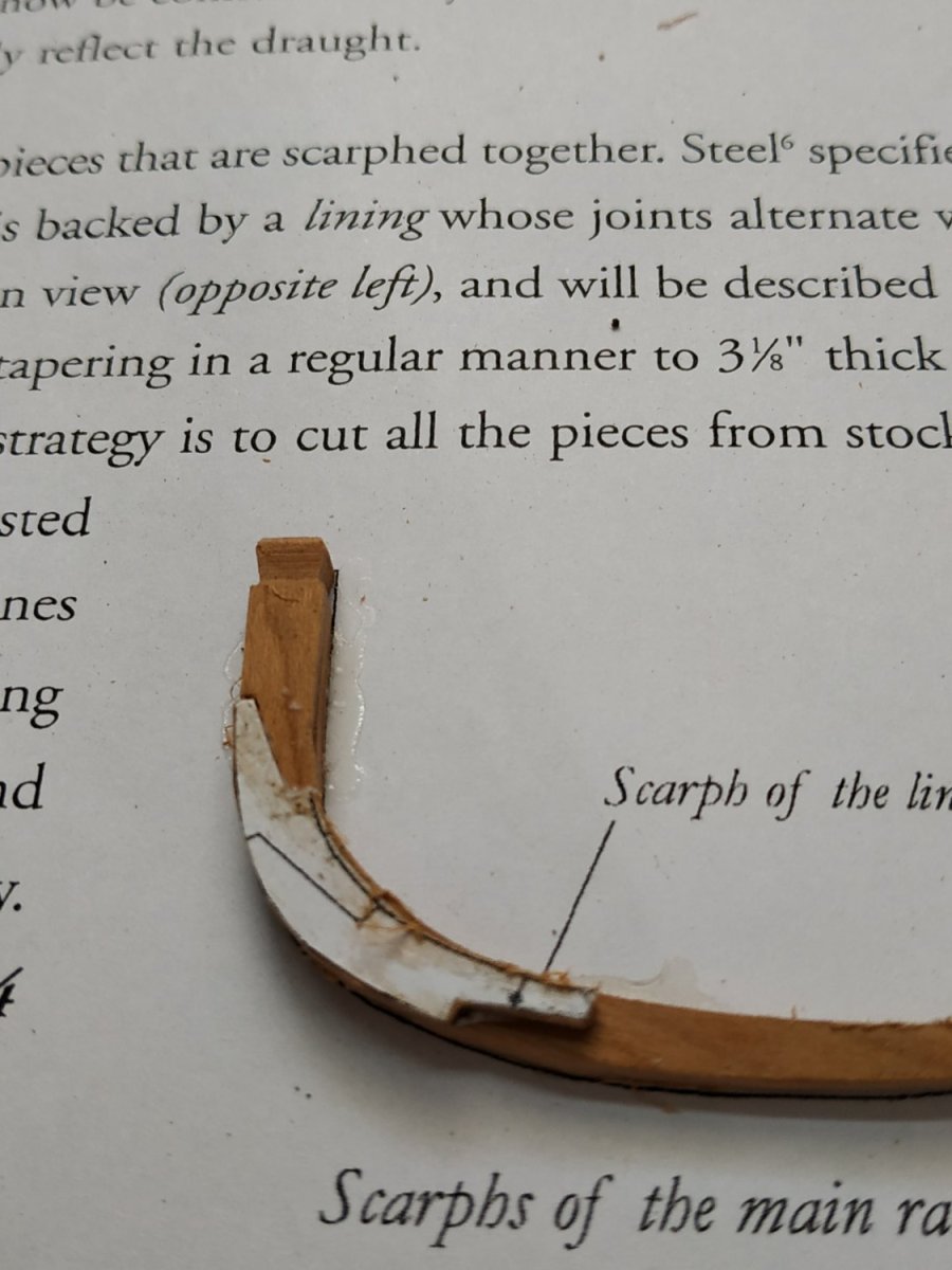
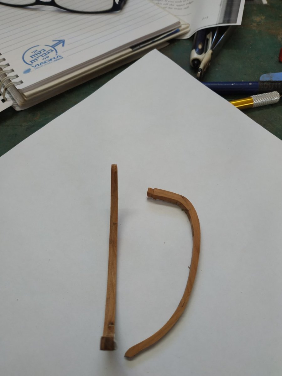
The Main Rail TFFM says not to worry-easier than it looks Ha! Ha! Good explanation about the plans distorting, but I didn’t understand the solution. So I just cut the pattern of the expanded example, backed onto card and it seemed to fit. The Rail consists of 3 parts- Main (outer), Lining(inner) and Planksheer(above). The first two have scarfe joints that are staggered. Stock for the outer rail is 2.9mm sq.- lining 2.9x1.33 mm. In order to make the Timberhead, I made the aftermost part of each rail first. These were placed in a jig so the shaping was consistent. (The Jig was milled and filled and the base of the groove is colored to show when to limit the shaping of the piece-using a sanding stick)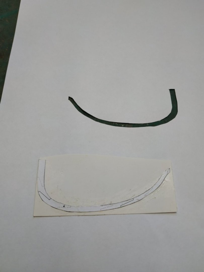

-
Swan-Class Sloop by Stuglo - FINISHED - 1:48
stuglo replied to stuglo's topic in - Build logs for subjects built 1751 - 1800
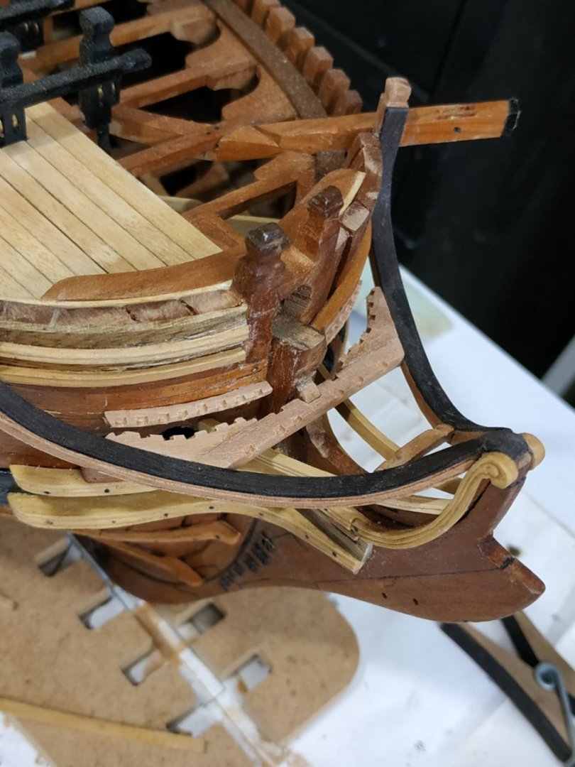
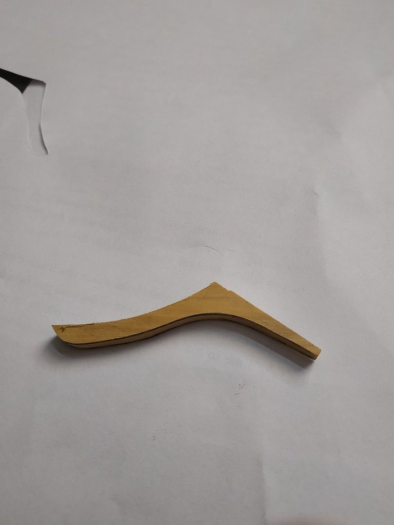
Wash Cant Placed under the Lower Cheek to act as protection. I misunderstood the instructions and made it too thick. Reviewing the 3D rendering, I saw that it thins toward its aft end. I reshaped it while in situ with a chisel blade and sanding stick. The spaced scores represent plank joints, as it is said not to have been made out of a solid piece of wood. Trail Boards Between Upper and Lower Cheeks. Variation among different ships as the aft extension. Thickness 1.6mm. It was carved, but I have simply used a variable-coloured grained wood. The is a Chock above either side of the Gammoning Slot. Its lower edge is rounded to facilitate the Gammoning. My chock is too narrow as the slit should have been lower. Bolster. A chock to reduce wear on the cables. Back shaped to fit hull. Thickness less than the lower Cheek it sits on. The groove extends half way up the Hawse holes (I removed the brass portholes and blackened the area to represent lead lining) The Bolster is rounded front and sides, attached with 3 pairs of bolts

-
Swan-Class Sloop by Stuglo - FINISHED - 1:48
stuglo replied to stuglo's topic in - Build logs for subjects built 1751 - 1800
forgot this picture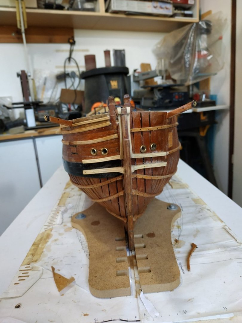
-
Swan-Class Sloop by Stuglo - FINISHED - 1:48
stuglo replied to stuglo's topic in - Build logs for subjects built 1751 - 1800
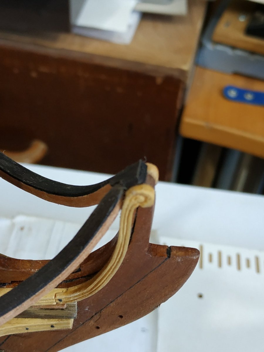
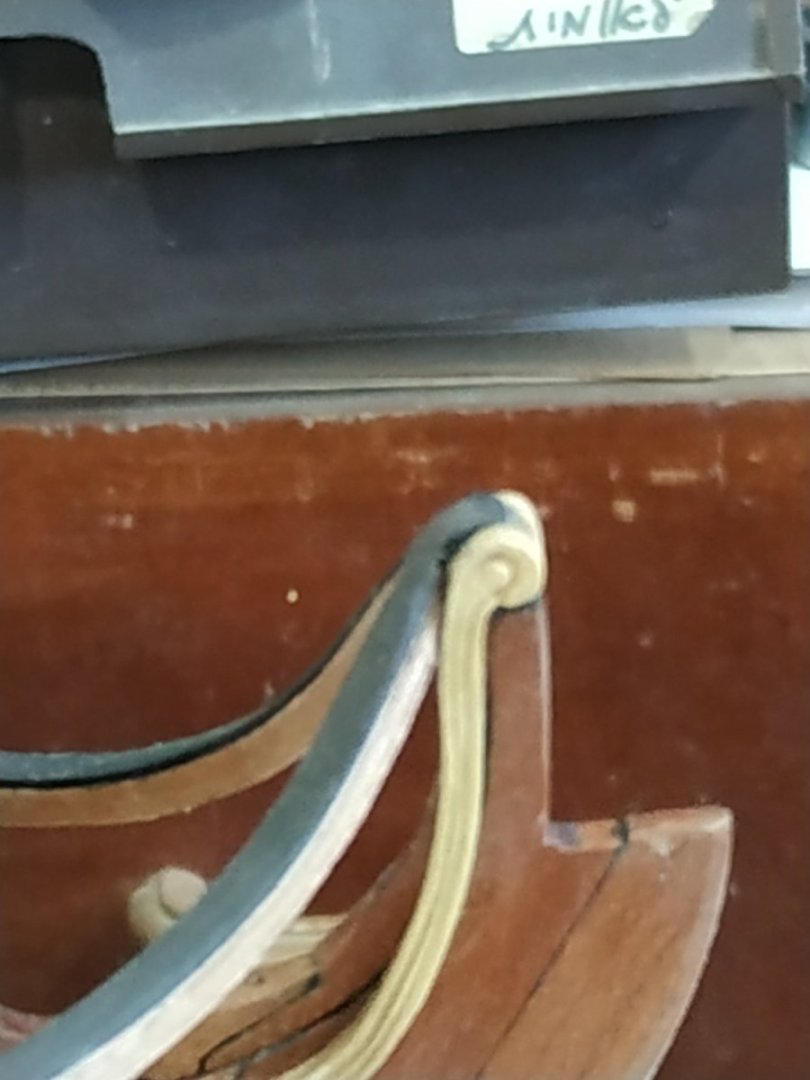
Upper Cheek Same basic shape as lower cheek but extentends upward and forward in an extra piece, called a Hair Bracket, that is connected by a scarf joint. The parallel part is separated from the Lower Cheek by a gap of 6.9mm It is sided at 3.18, narrowing to 2.65 forward, with width 4.0 to 1.6mm before widening at the top to 2.5mm The TFFM suggests making in the 2 parts, sticking them together, and then attaching them. I found that I couldn’t keep the aft part still without gluing it in place first. (Because the part is narrower, a new mold-maker was required) I made the Hair Bracket at more than double thickness, cut it in half with bandsaw, so that both halves would match. The topmost part , has a scroll or other fancy molding, and matches form of the Extension Piece of the Knee of the Head

-
Swan-Class Sloop by Stuglo - FINISHED - 1:48
stuglo replied to stuglo's topic in - Build logs for subjects built 1751 - 1800
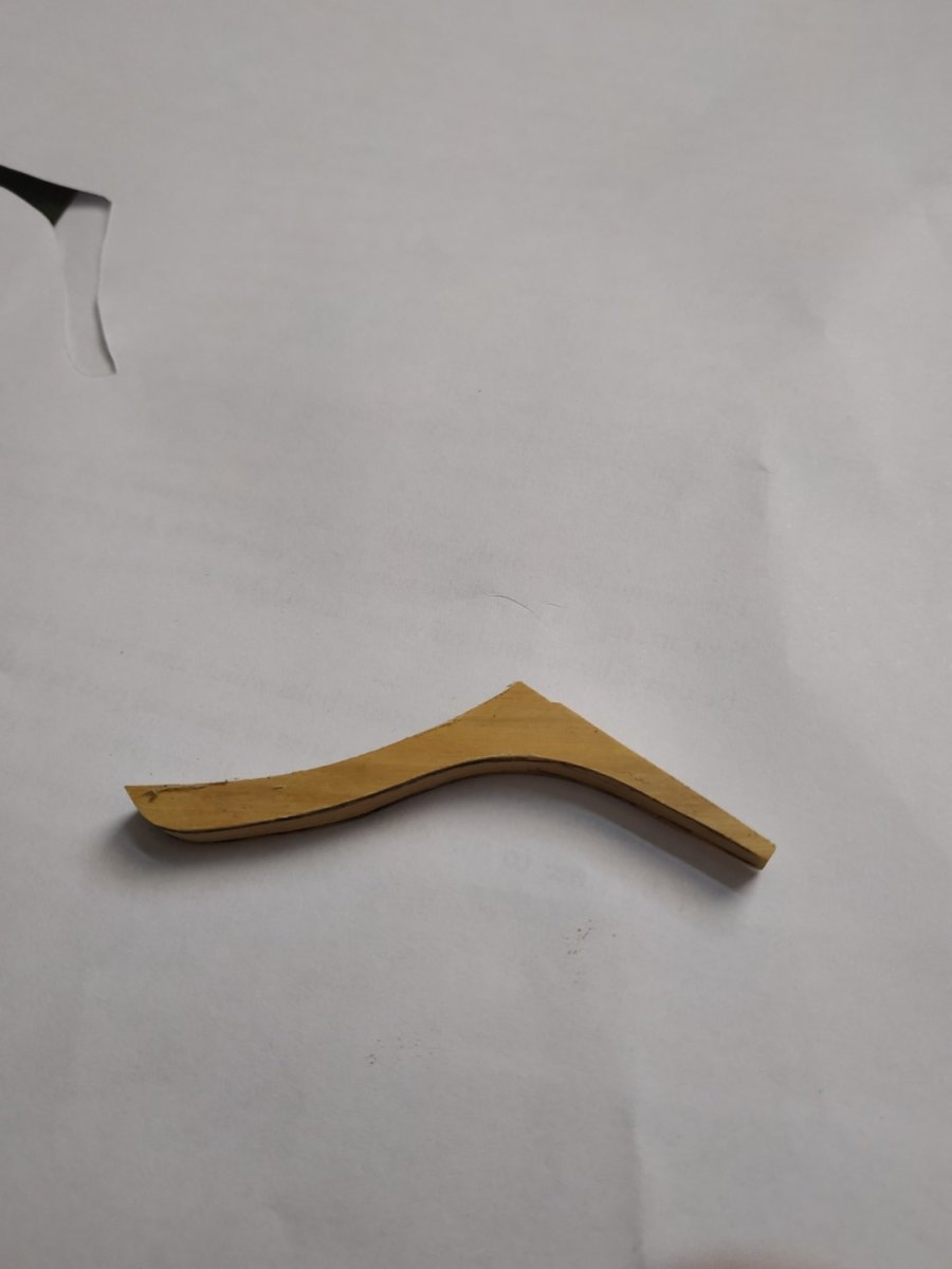
Structures of the Head. I always considered these the most difficult part of a build -even with a kit. TFFM seems to lay out instructions and an order that hopefully will minimize the stress and mistakes. Lower Cheek Shaped like a knee. Foreward arm, with slight upward curve- the arm against the hull almost straight and follows the lower edge of the center wale, to which it is attached. Sided 3.45mm-slightly tapering forward Depth (looking from above) 4.24 mm tapering to 1.72m (As no planks on port side, thicker part to compensate) I used the horizontal pattern then the side view pattern for cutting to shape and sanded to fit. Molding with a shaped chisel blade. The foreward extension is too long-will be altered later when the Figurehead is fitted.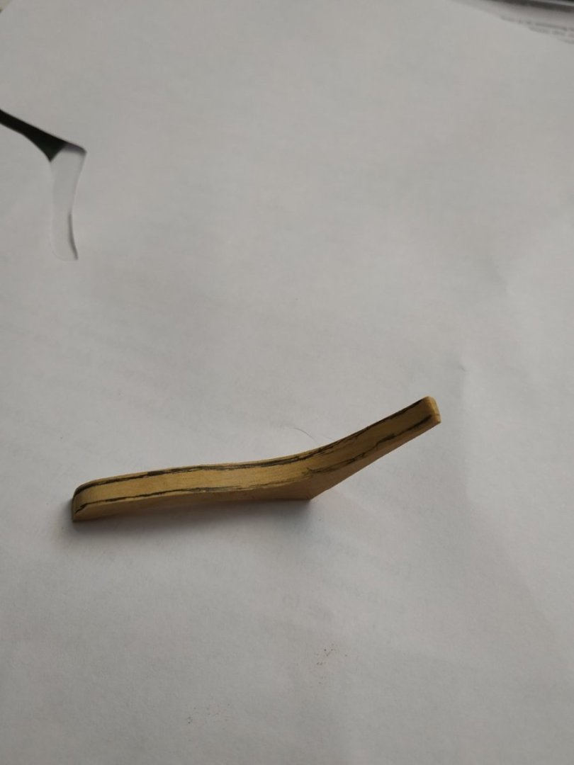
-
Swan-Class Sloop by Stuglo - FINISHED - 1:48
stuglo replied to stuglo's topic in - Build logs for subjects built 1751 - 1800
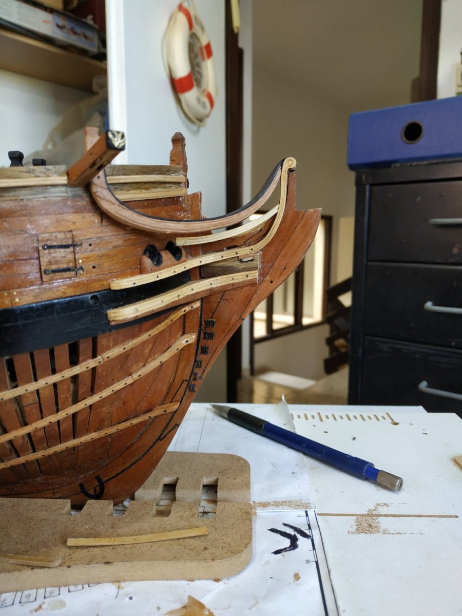
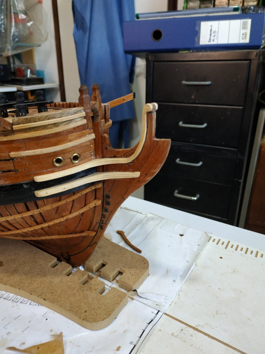
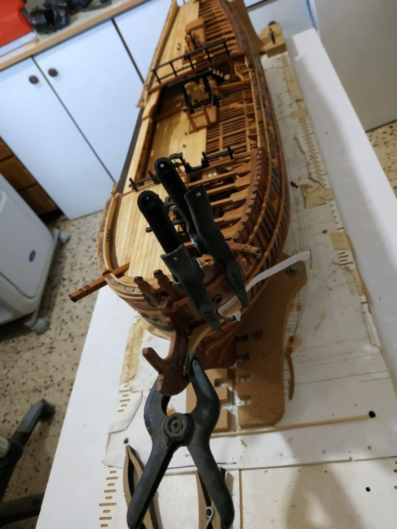
Fixed Gangway A short platform forward of the Quarter Deck. Supported by a frame, the top of which is level with the Planksheer (not yet fitted), and athwartship ends tenoned onto the string at the waist. Therefore the Gangway surface is proud of this. It is angled to match the deck camber. The perimeter beams are 2.12 mm sq-athwartship 1.12 x1.59 mm thick. The foremost frame sits between 2 knees.. The Gangplanks are 4.77mm wide and 1.33mm thick, surrounded by a frame 3.25mm wide, slightly larger than the frame it sits on. Planksheer. 1.6mm thick, overhanging the outer planking by 1.6mm, and flush with the inner hull planking. I found “molding” the outer edge impossible, and so only chamfered it. Gangplanks. A pair, each 4.77mm wide, sitting on knees previously fitted, outer edge against the planksheer at an angle to match the deck. Extends beneath the foredeck to the forepart of Gangway frame. The 2 planks are fastened together with bolts 25mm apart. Breasthook over the Bowsprit Fits just below the Drift Rail, 4.1mm thick- length along arms 70mm Sanded so the upper surface is flush with the toptimbers. The central part, underside needs hollowing out to allow fitting of the Bowsprit. This I did after gluing in place.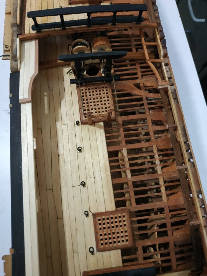
-
The best place is where you feel at home, with the one you love. If it happens to be a cottage by the sea on a tropical island, that's a bonus. ( the green is mould, not envy ha! ha!)
-
Swan-Class Sloop by Stuglo - FINISHED - 1:48
stuglo replied to stuglo's topic in - Build logs for subjects built 1751 - 1800
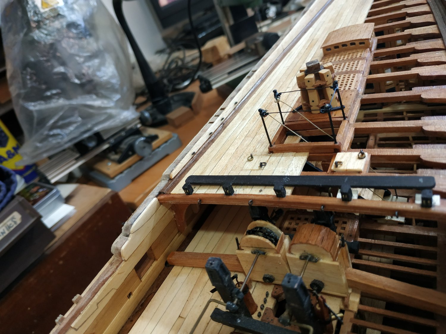
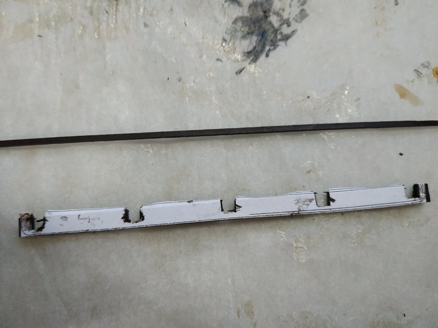
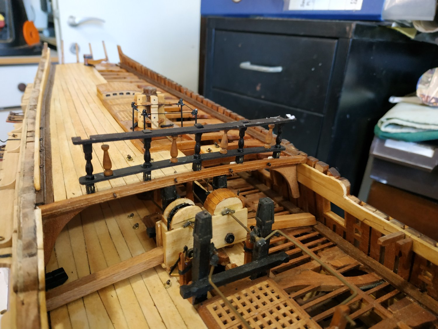
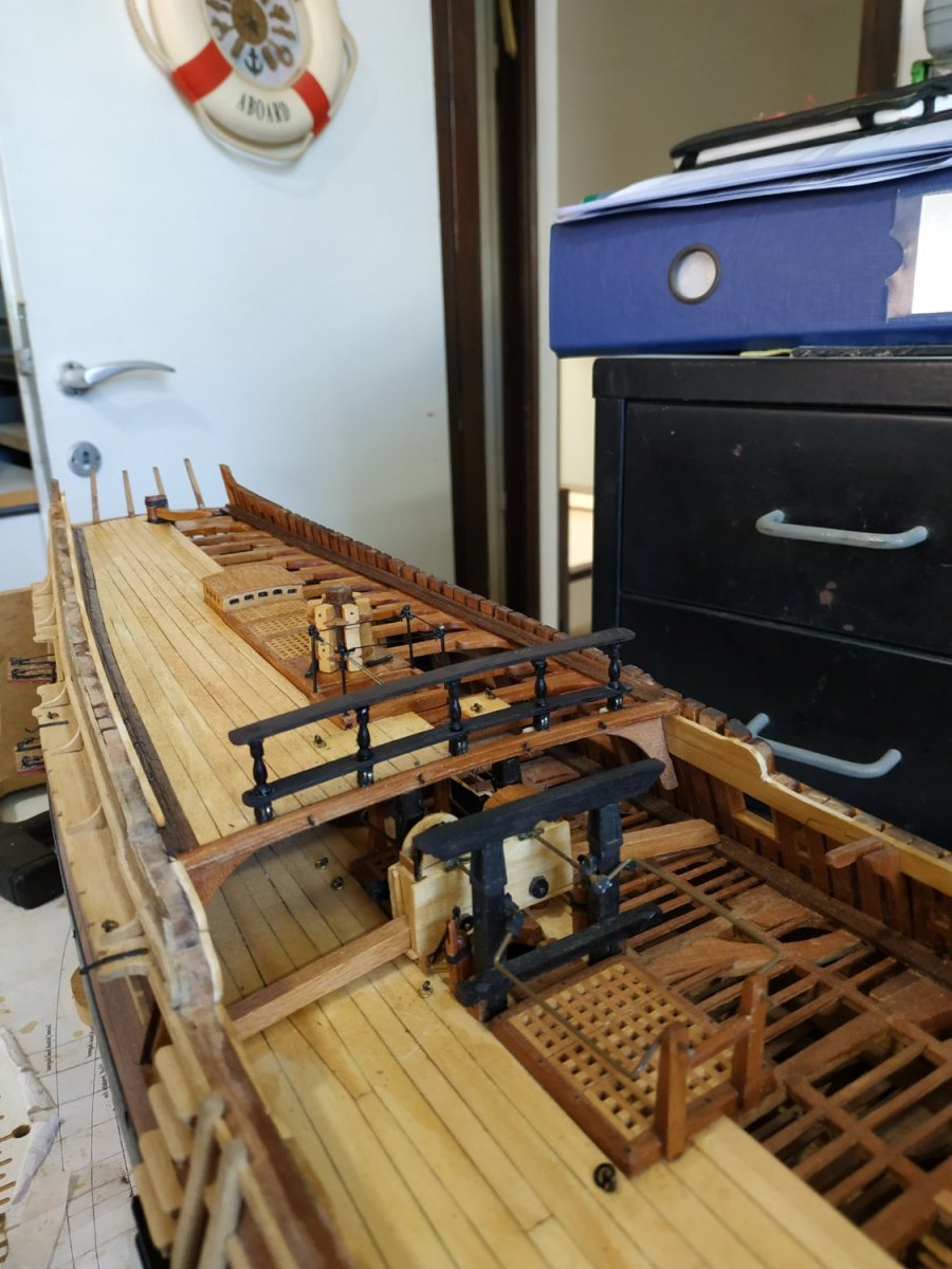
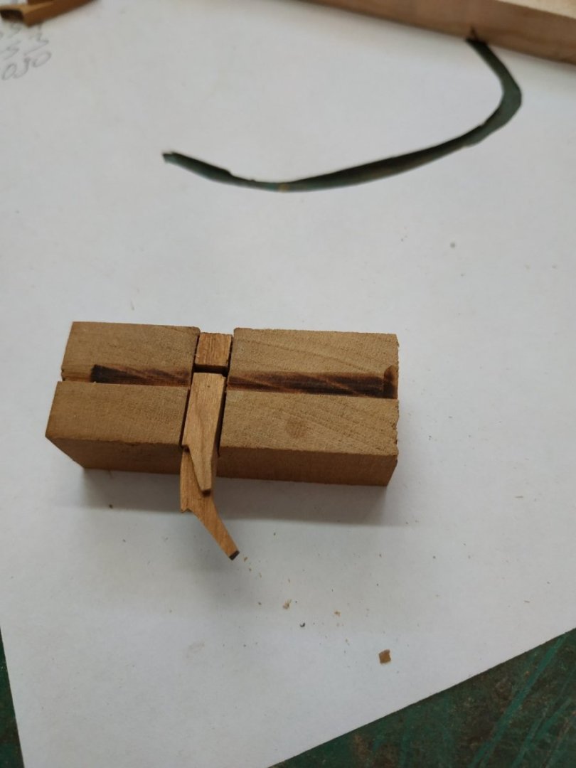
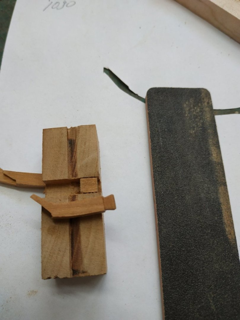
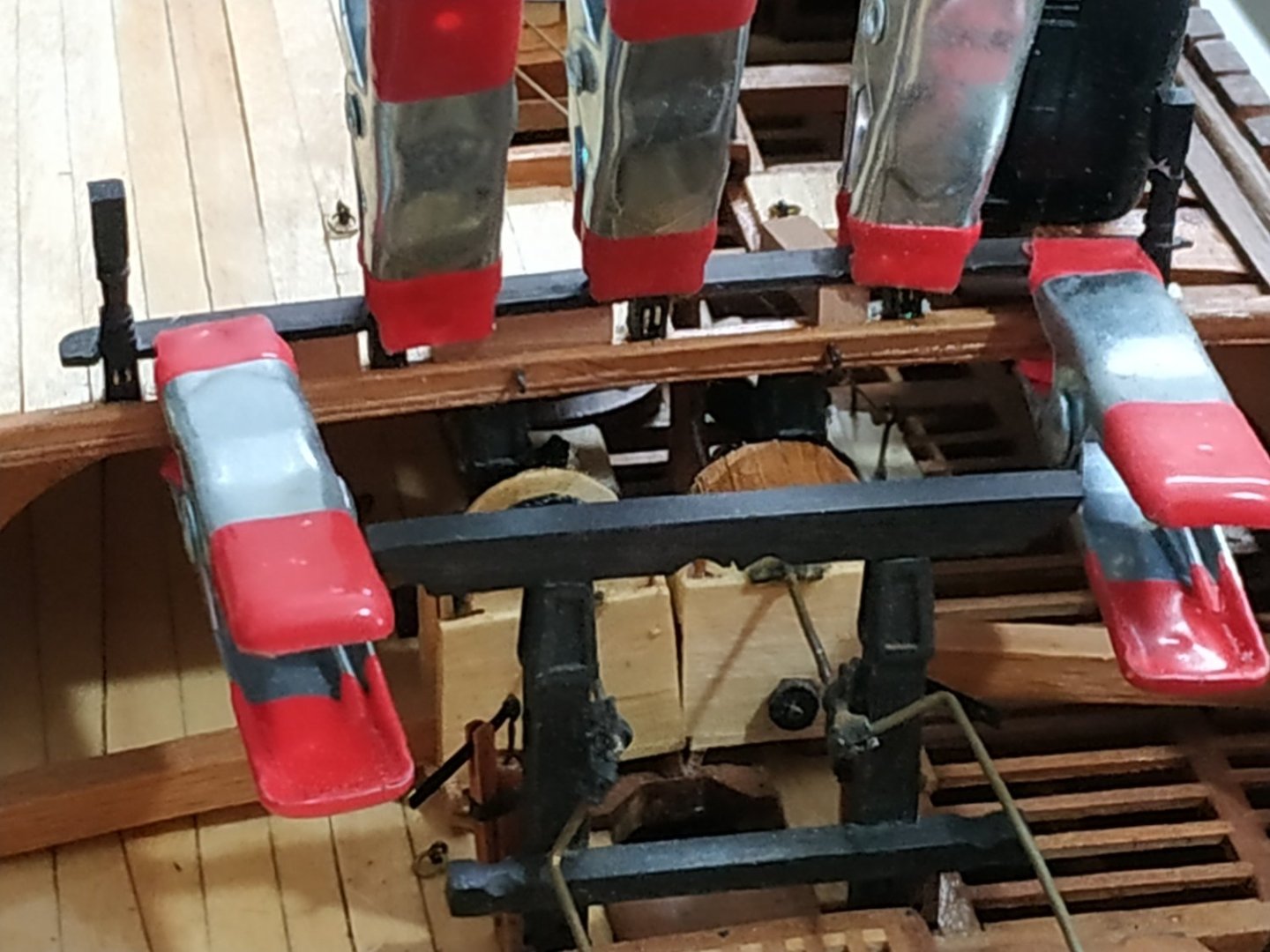
Quarter Deck Breastwork, revisited. Well that attempt was not exactly satisfactory, so try again. Start with the block for the whole length,turned using a shaped cutter fixed in the lathe. It Works !! I have found that cutting slots this thin, even with a drill press, doesn't give me a correctly-positioned hole/slit on either side of the piece, so I cut a wider slot, 1.6mm and put a 0.75 mm “wall” in the center to separate the sheaves. I think this looks better than the previous attempt. Don’t forget to pin as well as glue , to the deck- because I did !!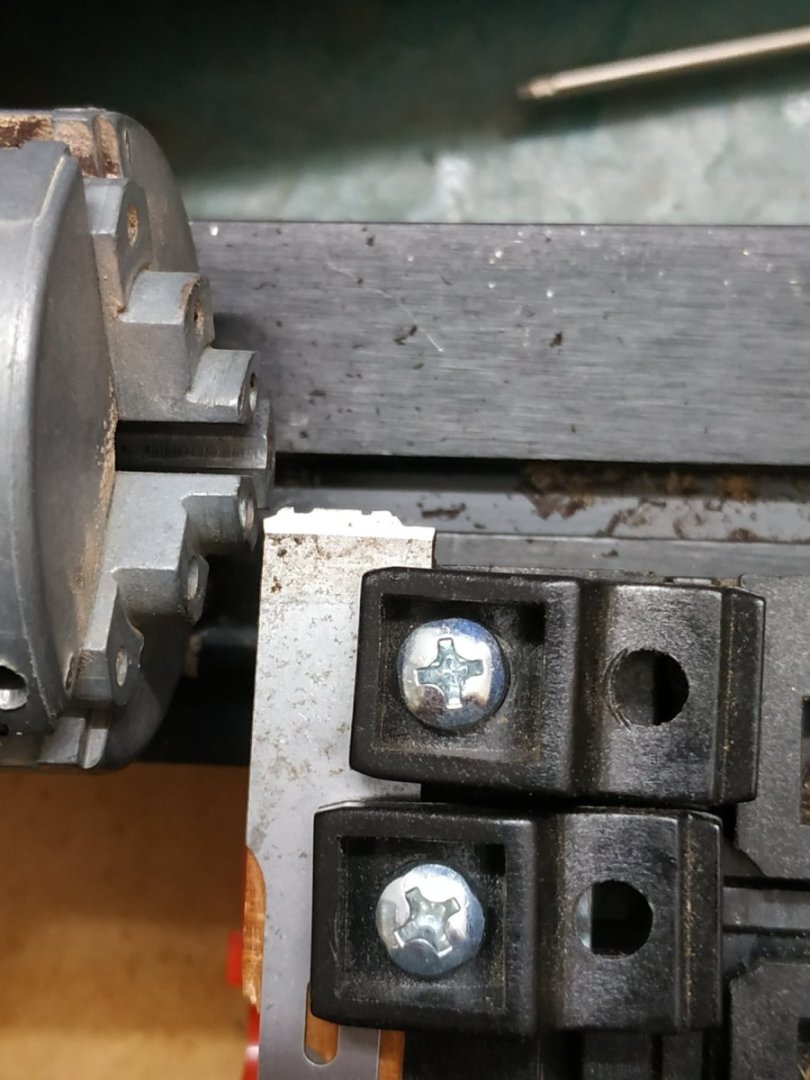
-
Swan-Class Sloop by Stuglo - FINISHED - 1:48
stuglo replied to stuglo's topic in - Build logs for subjects built 1751 - 1800
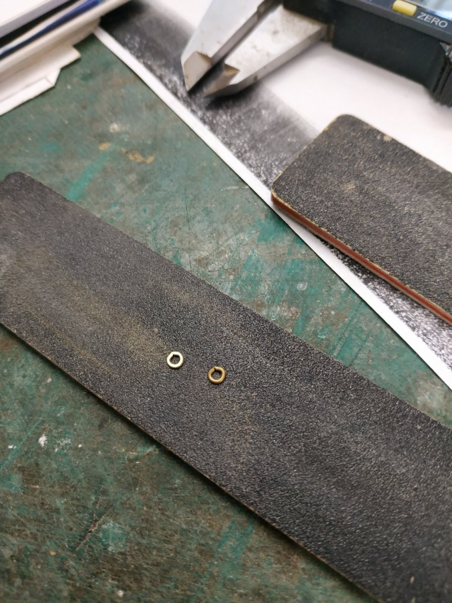
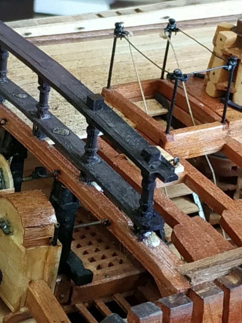
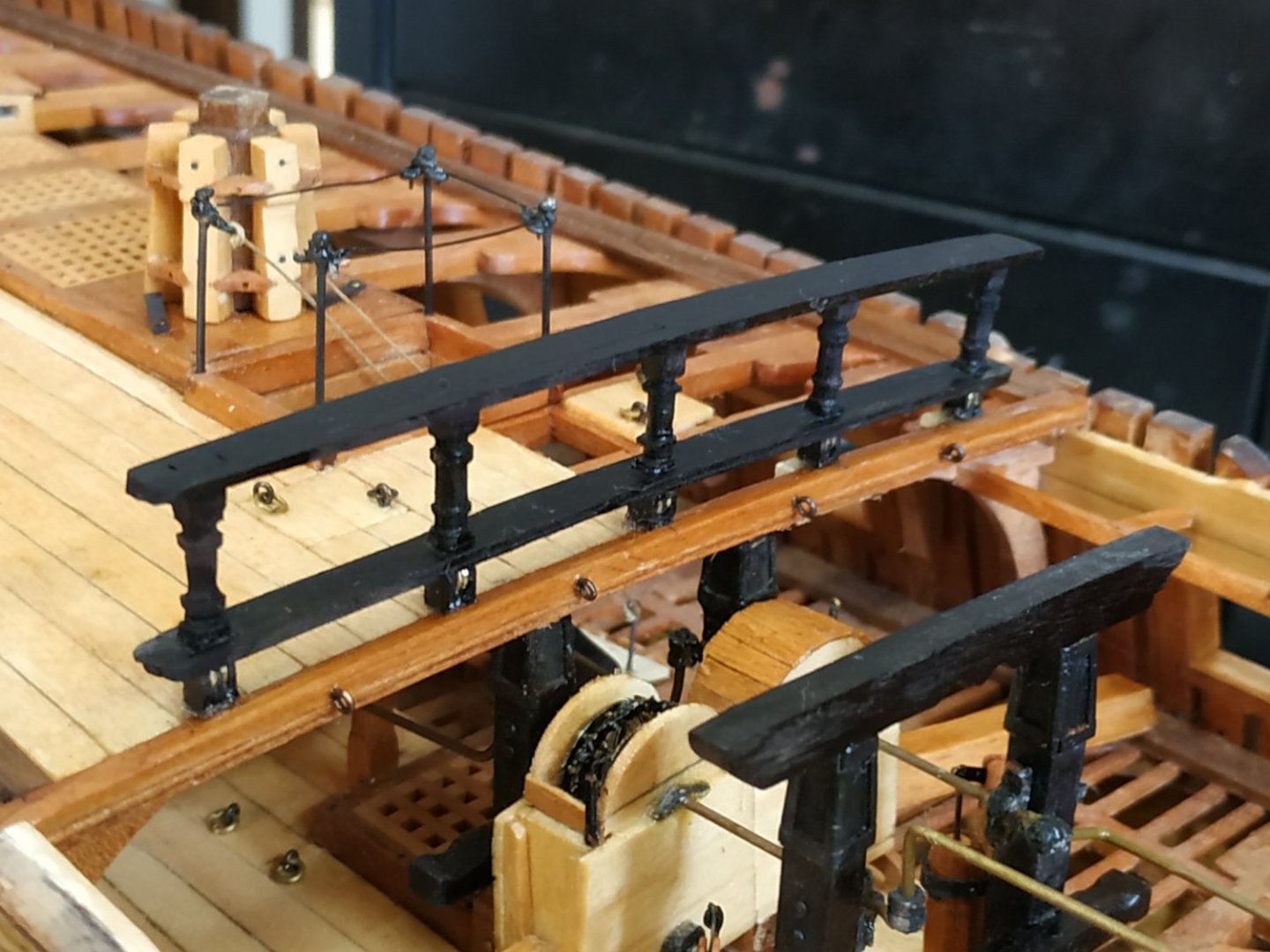
Quarter Deck Breastwork. Consist of 5 turned Stantions, paired base slots for 2 sheaves and 2 parallel Rails. Stock 3mm sq for stanchions- TFFM earlier showed a method of reproducing turned stanchions, but I can’t see how to adapt my primitive unimat 1. S used left-over stanchions from an old kit. Sheaves- 2.78x0.4mm . My brass rods are 2 or 4mm, so I took copper rings (2.9x0.74) and sanded them to correct thickness. For the slotted base- a “sandwich” of 0.7mm strips. The Rails : 5.5x1.33mm thick. As before, tenon for stanchion with a 1.25mm strip to enclose . Height extension of stantion with square stock, again enclosed by rail and sanded flush to its upper surface.