stuglo
-
Posts
707 -
Joined
-
Last visited
Content Type
Profiles
Forums
Gallery
Events
Everything posted by stuglo
-
Swan-Class Sloop by Stuglo - FINISHED - 1:48
stuglo replied to stuglo's topic in - Build logs for subjects built 1751 - 1800
Upper Deck Planking Finished, but when fitting the last plank, I realise I had miscalculated when numbering the planks on the plan and the result is a loss of a line of planking and the 3 butt pattern.Probably confused by the Waterway. In any case, I have to decide whether to rip it all up and replace or live with it. Must have been the Evil Eye.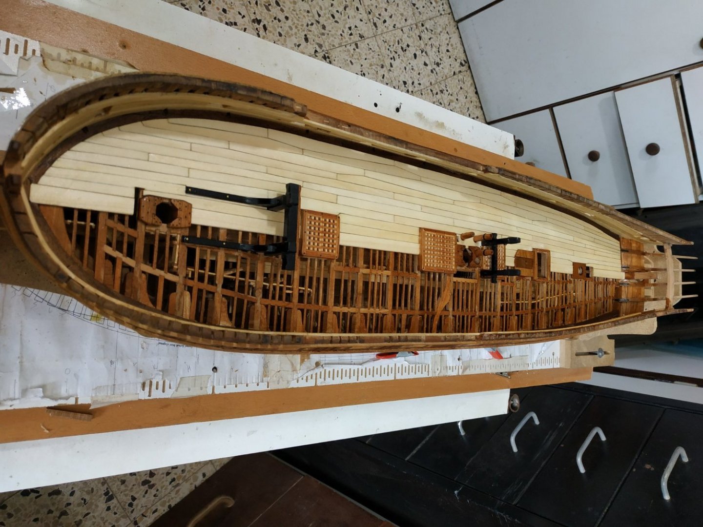
-
Swan-Class Sloop by Stuglo - FINISHED - 1:48
stuglo replied to stuglo's topic in - Build logs for subjects built 1751 - 1800
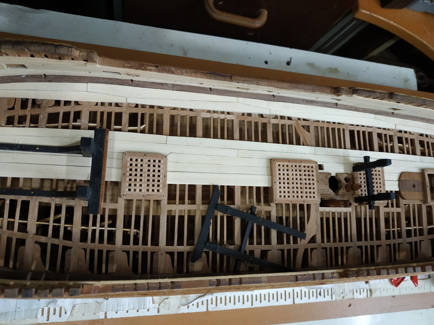
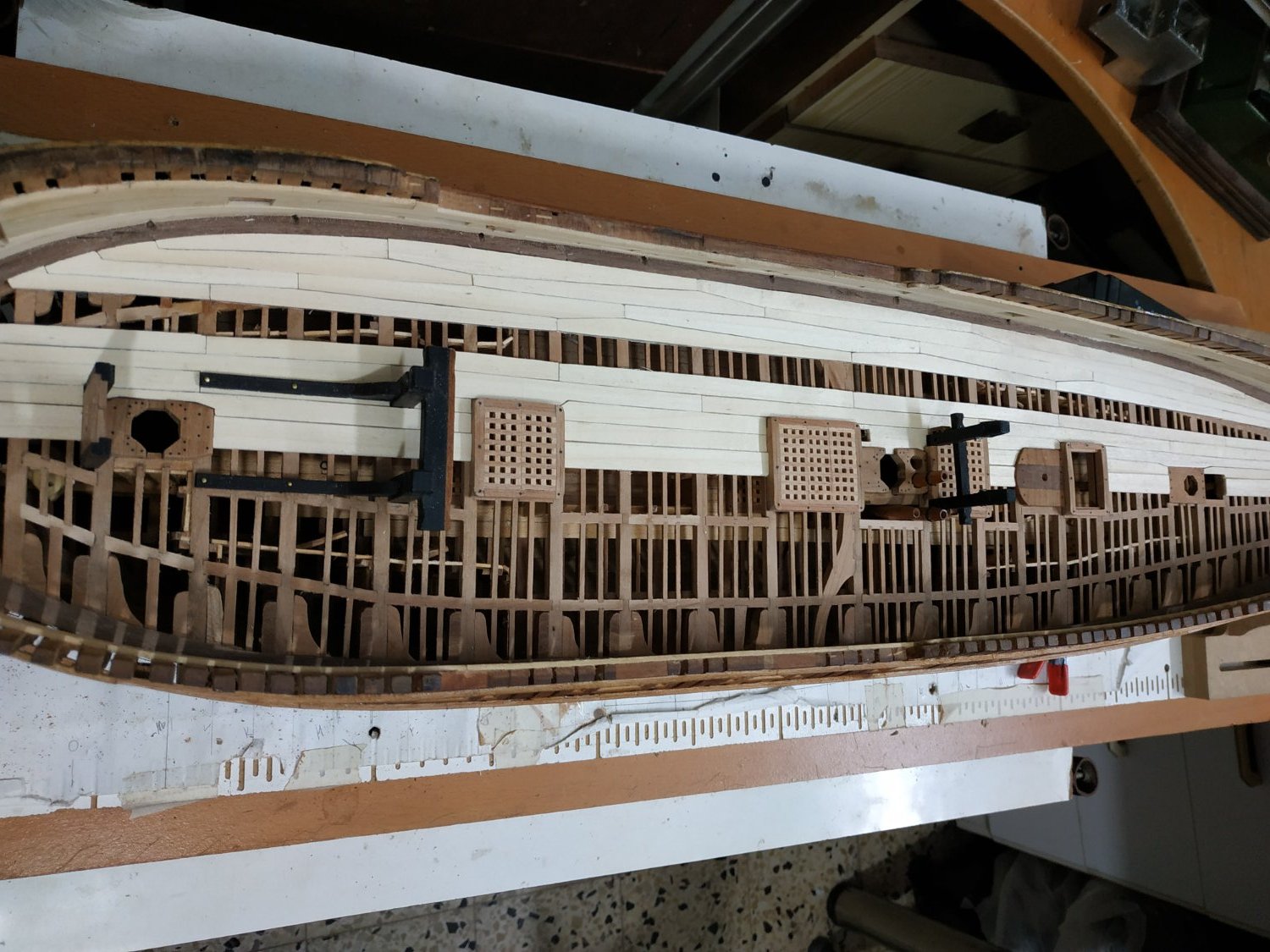
Planking the Upper Deck The planks are 1.6mm thick except for the Central or King plank, which is 2.12 mm. The Binding Strikes are also 2.12mm thick but Let Down to be level with the rest- ignoring this Let Down will allow use of 1.6mm planks as well. ( As previously noted, it seemed to me easier to make and fit the various hatches and Riding Bitt Standard, after fitting the King Plank) After fitting the Inner Strikes, the Binding Strikes (2 each side) are fitted. Noted is the widening to compensate for the difference in width of the Hatches. Note also that the Planks taper and curve. I simply used printed copies of the planking pattern of TFFM, cutting out each section, with some spare, and shaping them using my Proxxon Belt Sander, which I found quicker and more accurate than a plane. After these planks, I decided to jump ahead and make the outer 4 plank lines which are Top and Butt jointed. I did this because I thought this aesthetically important feature should be made as accurately as possible, any adjustments will be made to the intermediate plans later. I started from the outermost Plank line (next to the Hull). Again, using cut-outs from the pattern, these were made and fitted fairly quickly. (Only had to remake one of them) By using the patterns and fitting the wood directly, I didn’t have to side bend the planks, and avoided multiple calculations to decide the widths.


- 475 replies
-
- 10
-

-

-
Swan-Class Sloop by Stuglo - FINISHED - 1:48
stuglo replied to stuglo's topic in - Build logs for subjects built 1751 - 1800
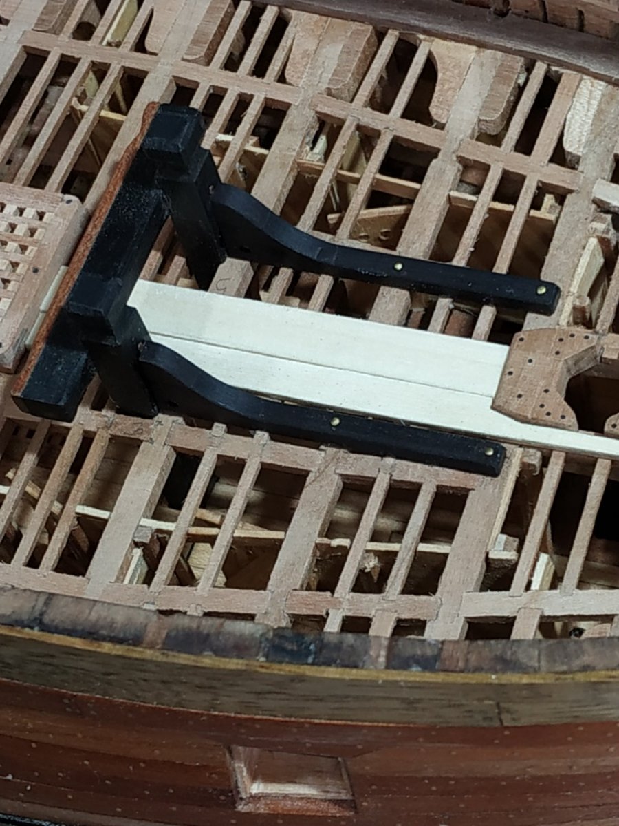
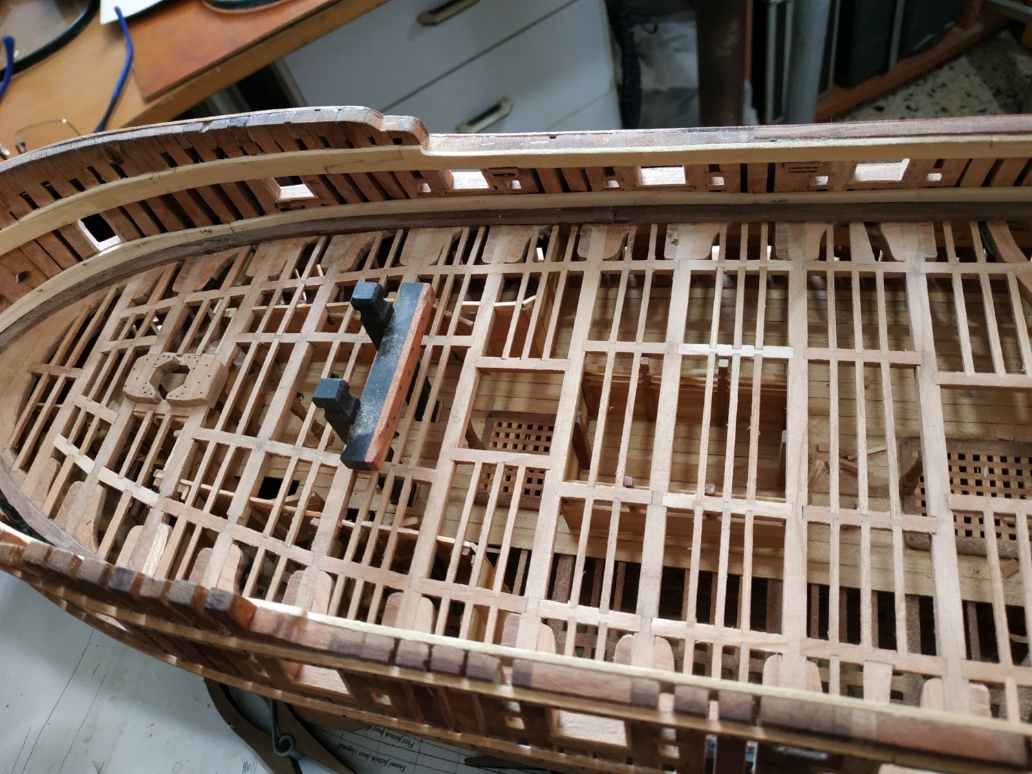
Riding Bitt Standards. These are inverted knees for the R.B. Pins. As they sit on the Beams, I think this is also easier to make and fit before the Decking is fitted. They are 4.3mm thick, profile and length (53.0mm)as per plans. They are scored by 0.53mm where they are let down on the Beams and Ledges. Holes are drilled -1.46- for the Cable Stoppers, in the corner near the Pins and Deck. Upper edges are chamfered.
-
When I was a kid, I remember the barbers using a lighted taper over newly cut hair .(? seal against some suspicion of loss) -never saw anyone go up in flames. Obviously, use a rapid once-over. If the worse happens, you have a model of a fire-ship!!!!
-
Swan-Class Sloop by Stuglo - FINISHED - 1:48
stuglo replied to stuglo's topic in - Build logs for subjects built 1751 - 1800
-
Swan-Class Sloop by Stuglo - FINISHED - 1:48
stuglo replied to stuglo's topic in - Build logs for subjects built 1751 - 1800
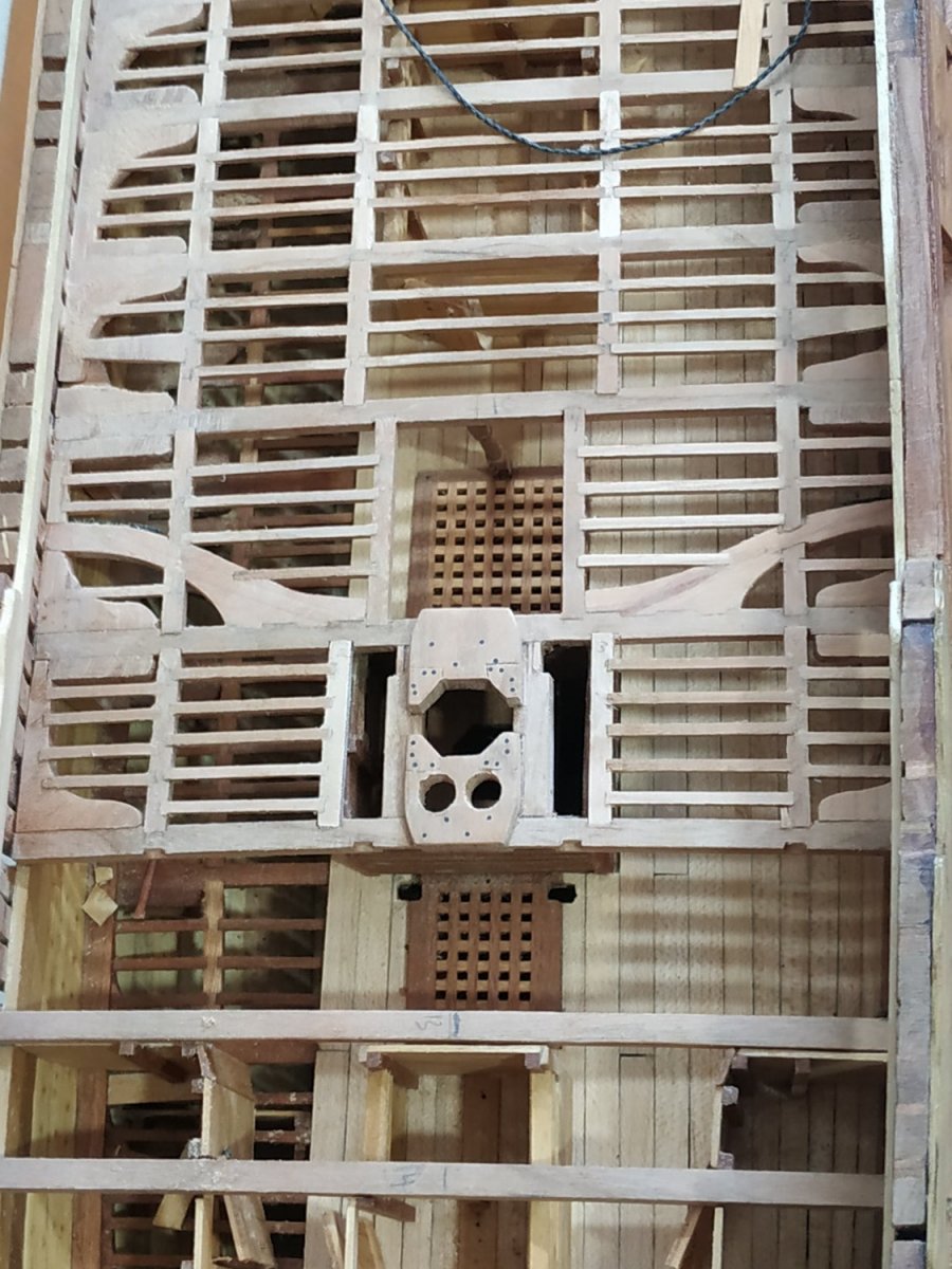
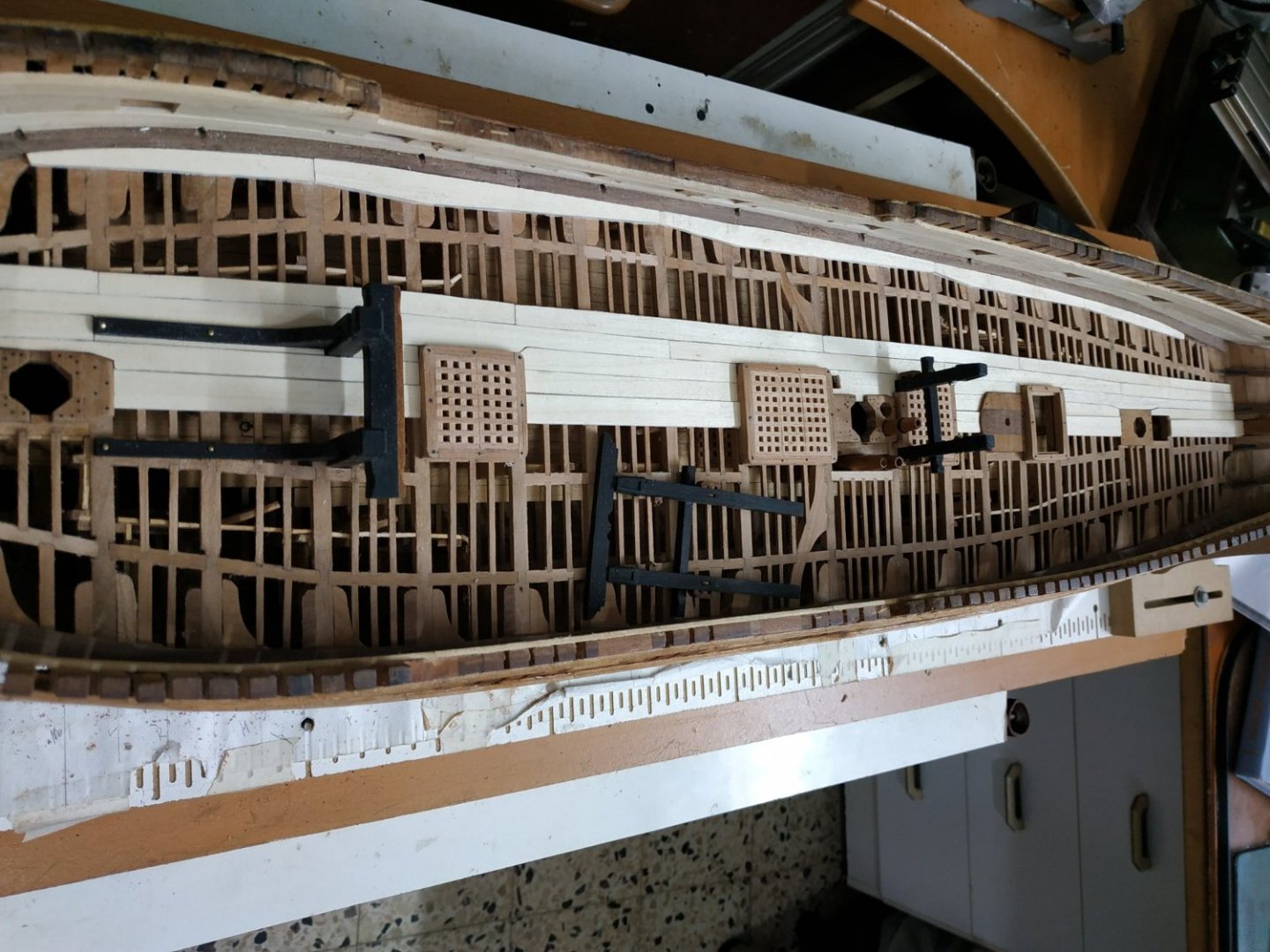
Hatch Coamings. As I find it easier to fit the planking around the Hatches, I will make these first. They are deeper than their lower deck counterparts. The Coamings are 5.3mm deep and 3.71mm wide. The Head Ledges are 5.55mmdeep (allowing for the rounding up of the beams) and only 3.18mm wide. A Rabbet is only cut into the Coamings (1.6x1.6mm) to receive the Gratings. At the corners are half-lap joints- the Head Ledge being uppermost.The upper part of the cornes will later be rounded. Above the level of the deck, the outer edges of the Coamings and Head Ledges taper inwards by 1mm (This will be done after the deck is fitted. Along with Head Ledges the Gratings are rounded up to match the beams. Some of the Hatch Coamings need modifying to allow for fittings such as Bitt Pins. Note Main and Aft Hatches have the same width, as do the foreHatch and Ladderway. The Gratings are divided-2 for the fore and aft hatches: 3 for the main. I found it easier to make these and fit the “framing” later. Remember to align all Grating Battens for-aft. -
If cotton or linen thread has the "fuzzies" even after fitting, try judicious use of lit taper or match to singe the buggers
-
Swan-Class Sloop by Stuglo - FINISHED - 1:48
stuglo replied to stuglo's topic in - Build logs for subjects built 1751 - 1800
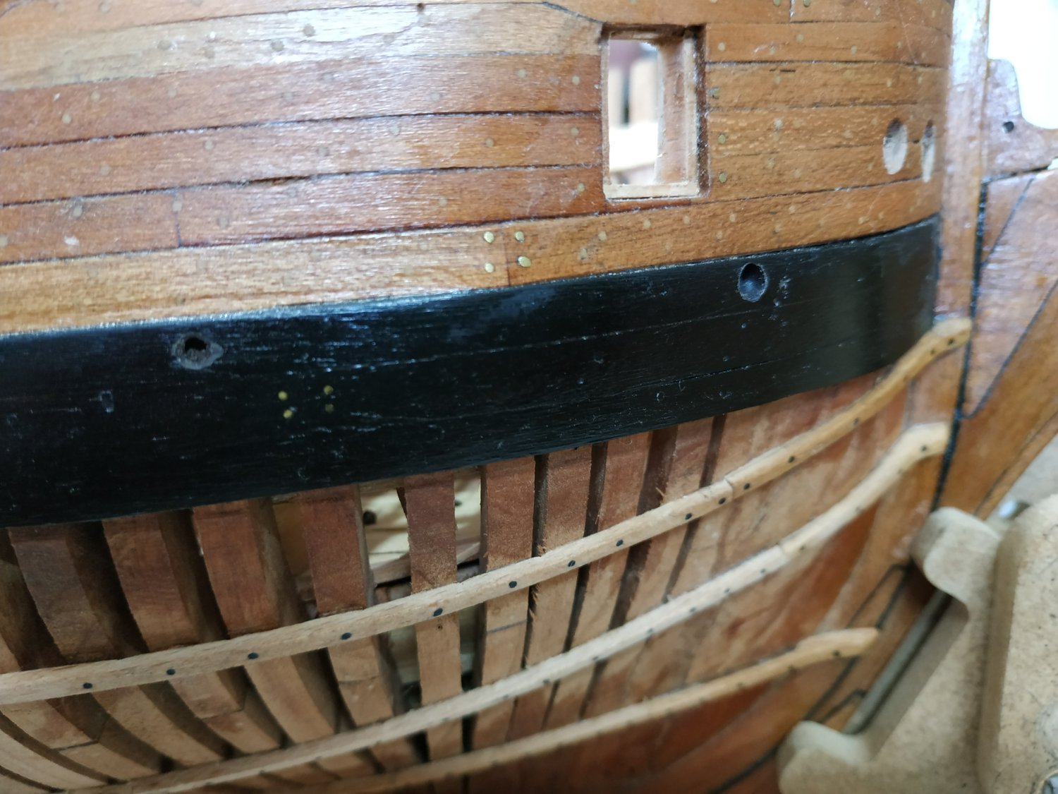
Not really, without re-making the Wale. I remember the correction, but forgot to refer back to the correct plan. But Peter Goodwin's book shows them going through the Wale. (and states that they are rarely shown on plans- as is with those I have). The slope angle would be too slight in my build. Also the 3D rendition shows through the Wales. Perhaps the illustration on pages 14-15 need correction. The experts are invited to comment. (PS luckily, I haven't rushed to correct this yet) -
Swan-Class Sloop by Stuglo - FINISHED - 1:48
stuglo replied to stuglo's topic in - Build logs for subjects built 1751 - 1800
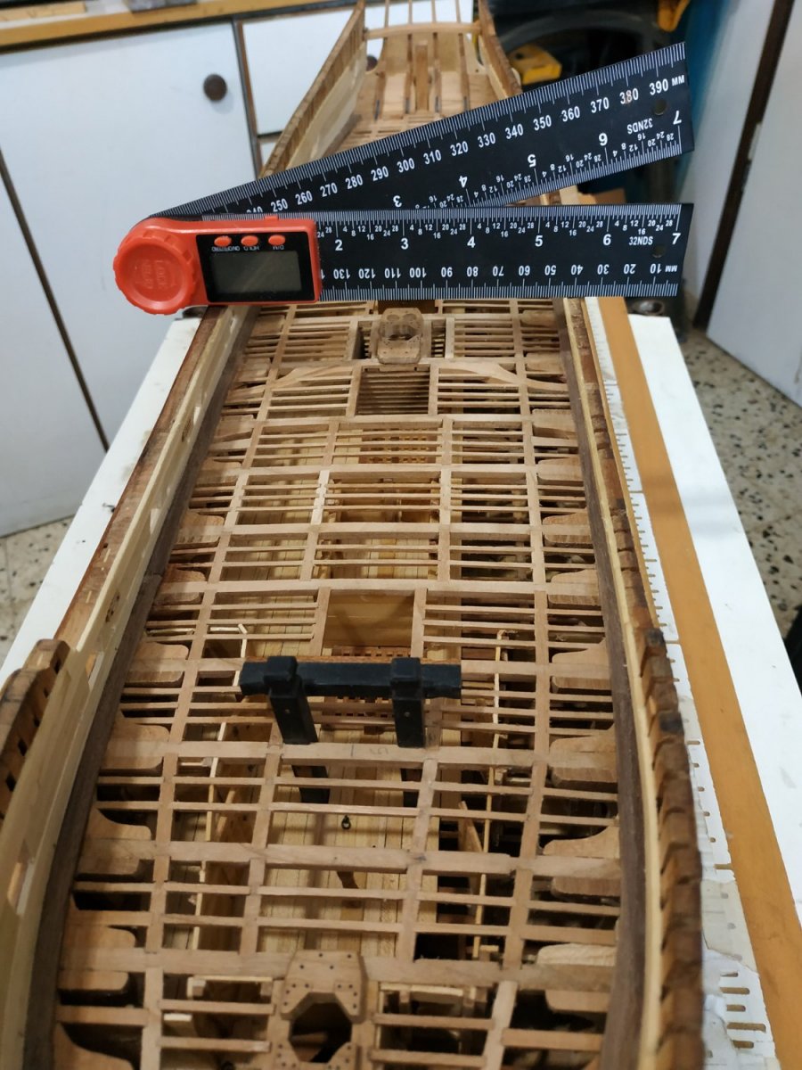
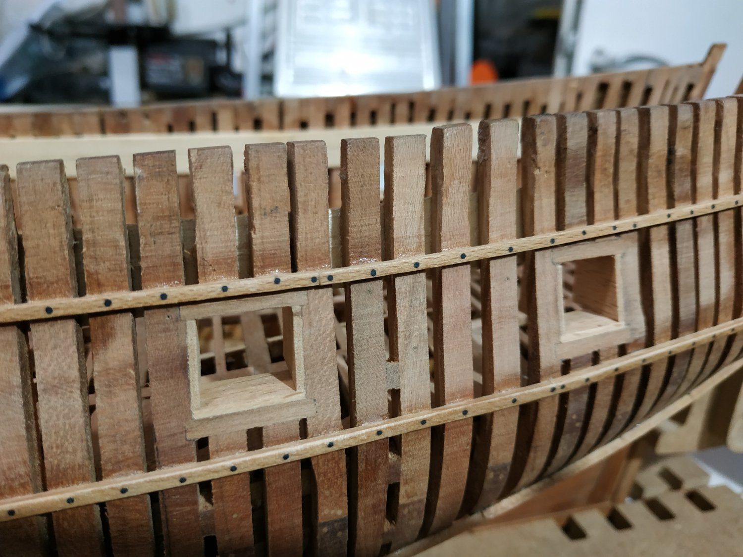
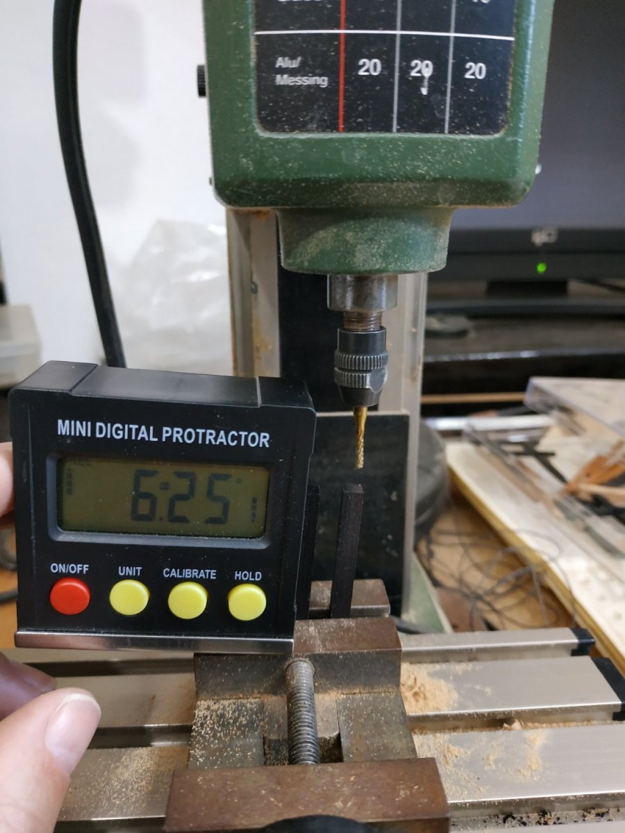
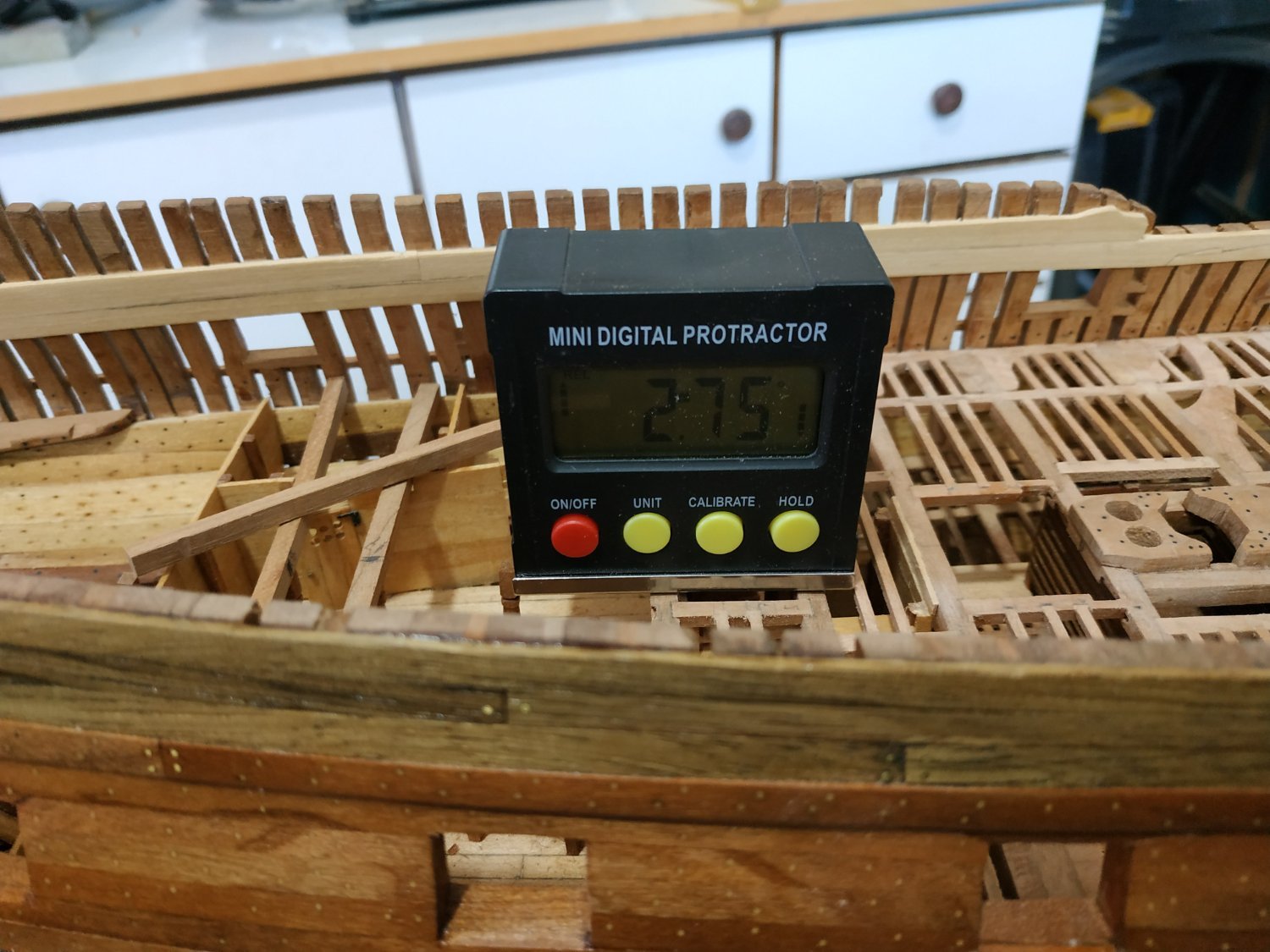
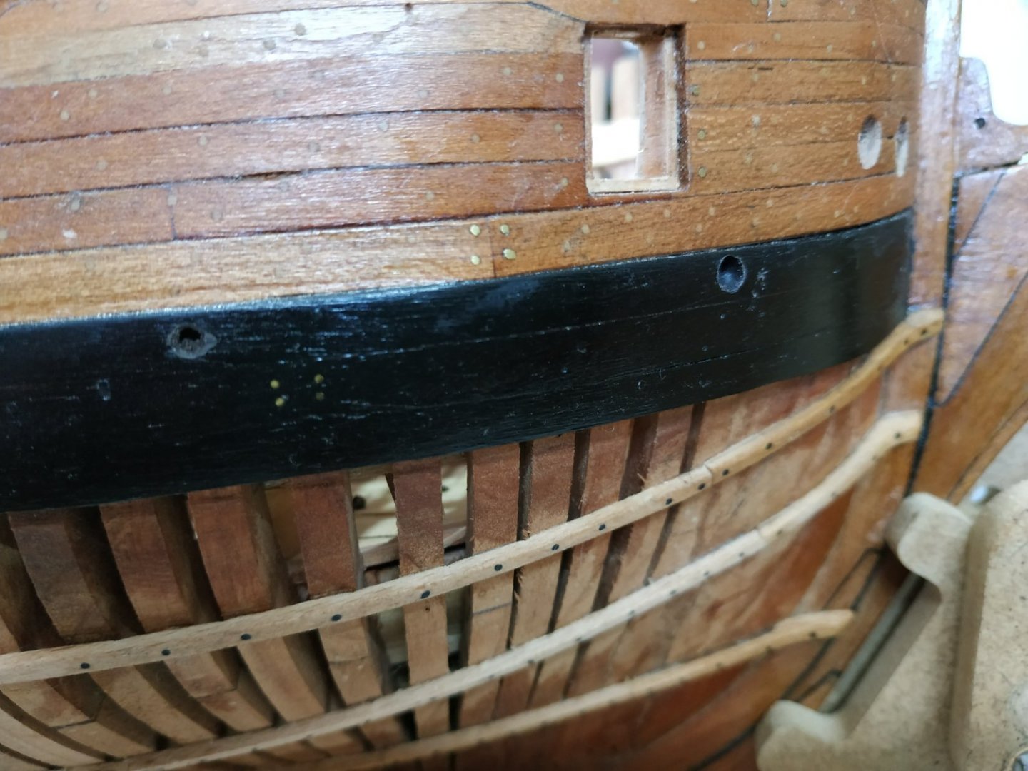
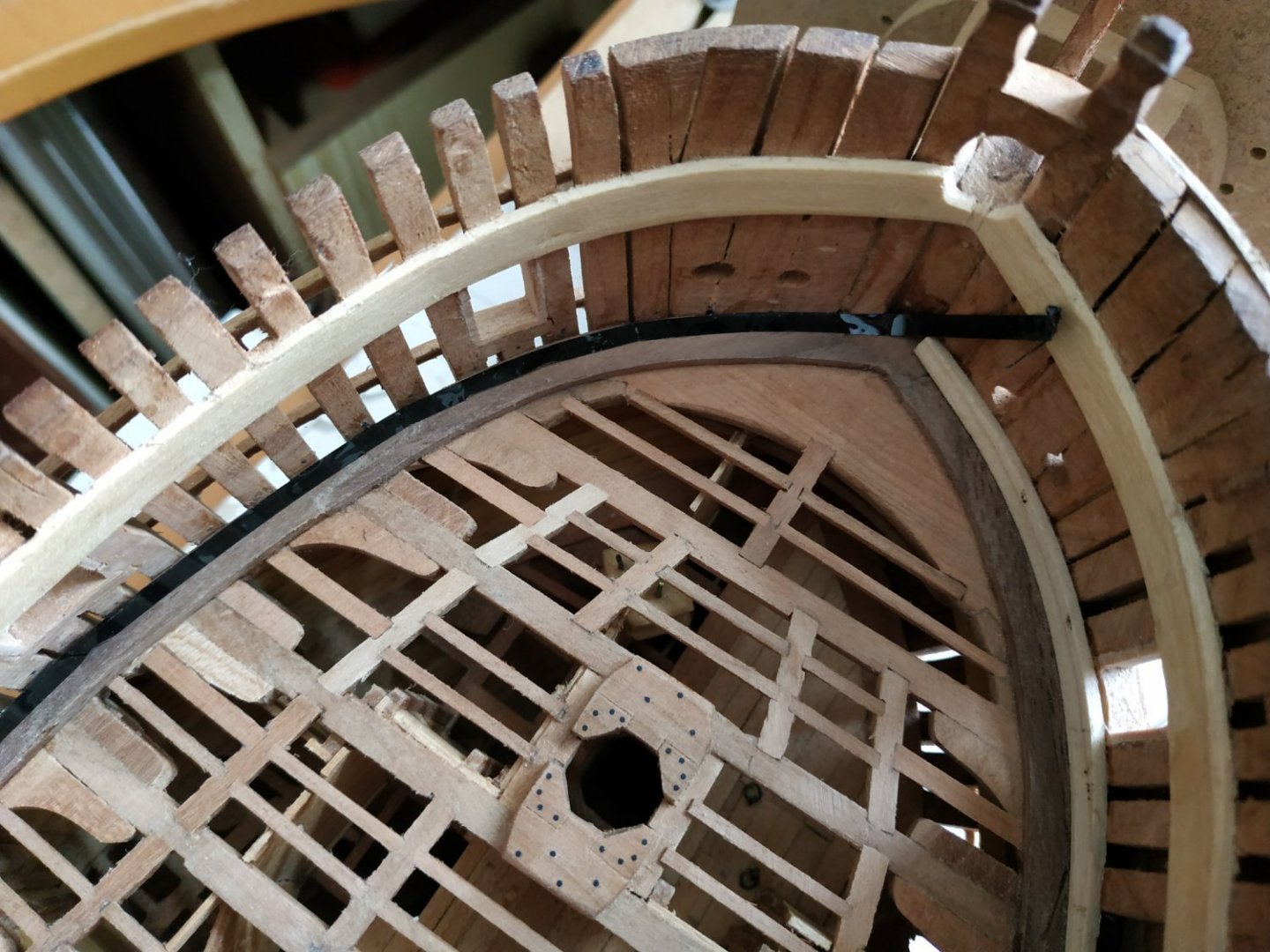
Scuppers - Upper Deck Drainage Tubes Quite apprehensive about making these - opportunity for big time screw-up, especially trying to angle down from the outer side of the Waterway, to the Wale at the correct and consistent line. Using the TFFM drawing, estimate angle at 15deg., and use my digital protractor to guide my Dremel drill. Use a 8mm bit for a guide which will allow me to correct afterwards. There are 7 Scuppers- 5 with an inner diameter of 2.12mm. Another 2, the Manger and the Pump Dale,are 2.65mm (All shown on the various plans.) We are told the Scuppers pass between the hull Frames where they are reinforced by small Scupper Support Blocks. Most lie beneath Sweep Ports, where frames are”shifted”. They are supposedly lined, but I haven’t found a way of doing it yet. HELP and SUGGESTIONS welcomed.
-
Swan-Class Sloop by Stuglo - FINISHED - 1:48
stuglo replied to stuglo's topic in - Build logs for subjects built 1751 - 1800
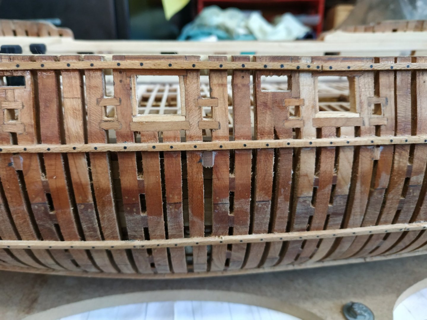
Upper Deck Spirketting These are the strakes #22 and #23 They are 1.6mm thick. Top and Butt joints. The upper edge of #23 is in line with the bases of the Gun Ports (except aft). It is also horizontal, NOT right angles to the face of the frame. The upper edge is chamfered to meet the thinner Quickwork above. The foremost #23 is wider so as to include the lower part of the Hawse Holes. Upper Deck Quickwork These are strakes #24,#25,#26- filling the gap between the Gun Ports. They are 1.06mm thick. The foremost #24 encloses the rest of the Hawse Holes.

-
"So that's my experience with coppering using plates!" Good work. Some observations as I've made this and the Diane with copper plates. From my reading, they were laid out in several bands which then involve lots of cutting and shaping.(Blade + sanding) . The self adhesive copper strip cut to length, was great for a smaller scale boat- not sure at this size. I found overlapping impossible. Slower acting or CA gel minimally applied and slide the plate into position. The copper will age naturally over time -I wasted time and effort preventing/accelerating and trying for uniformity. Let nature take it's course
-
Swan-Class Sloop by Stuglo - FINISHED - 1:48
stuglo replied to stuglo's topic in - Build logs for subjects built 1751 - 1800
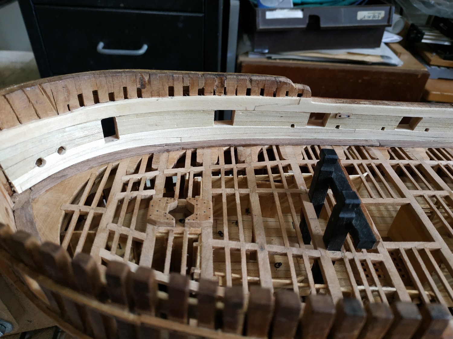
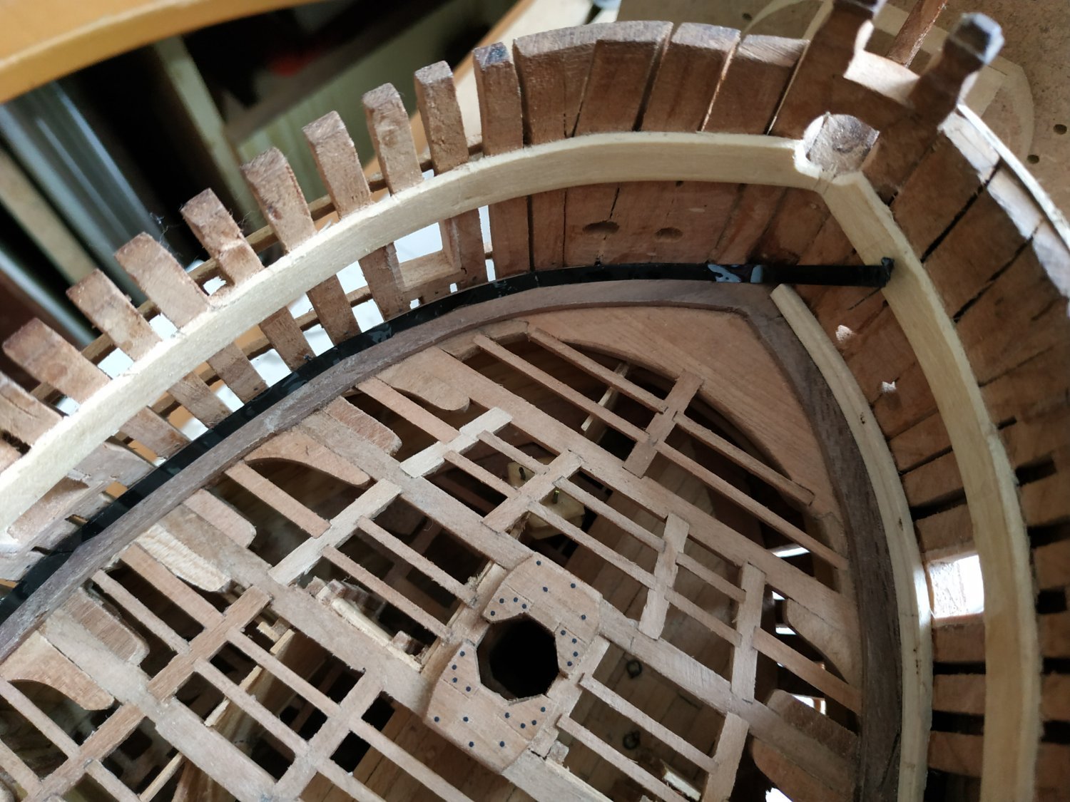
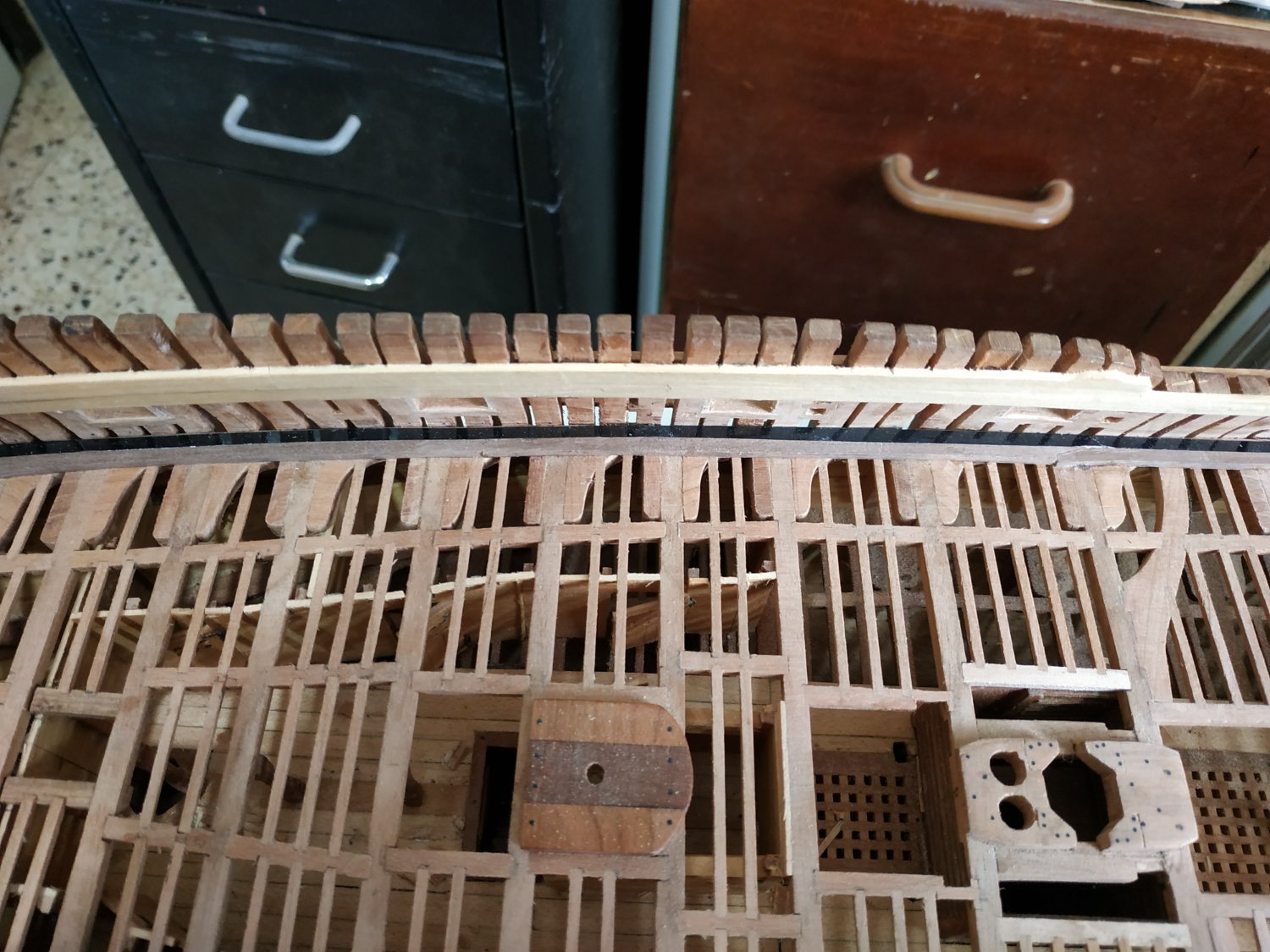
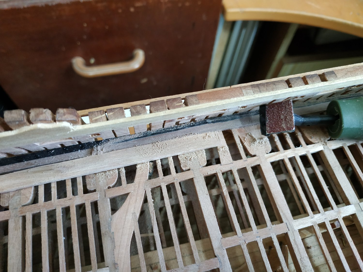
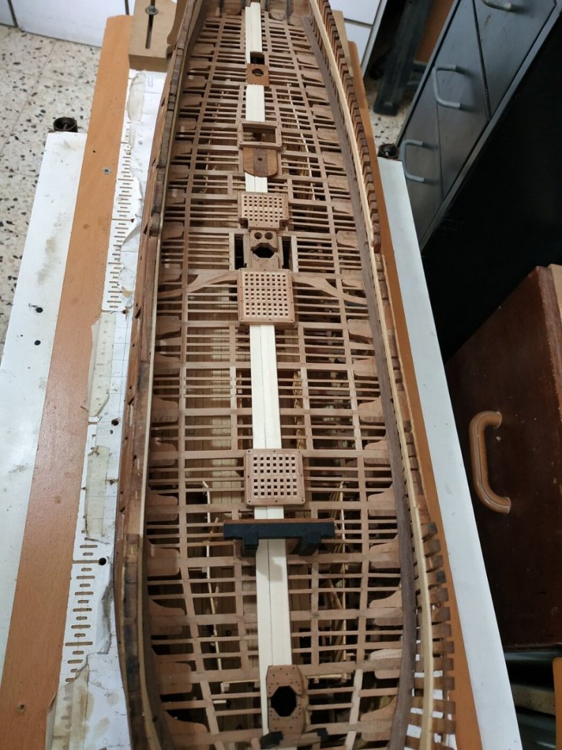
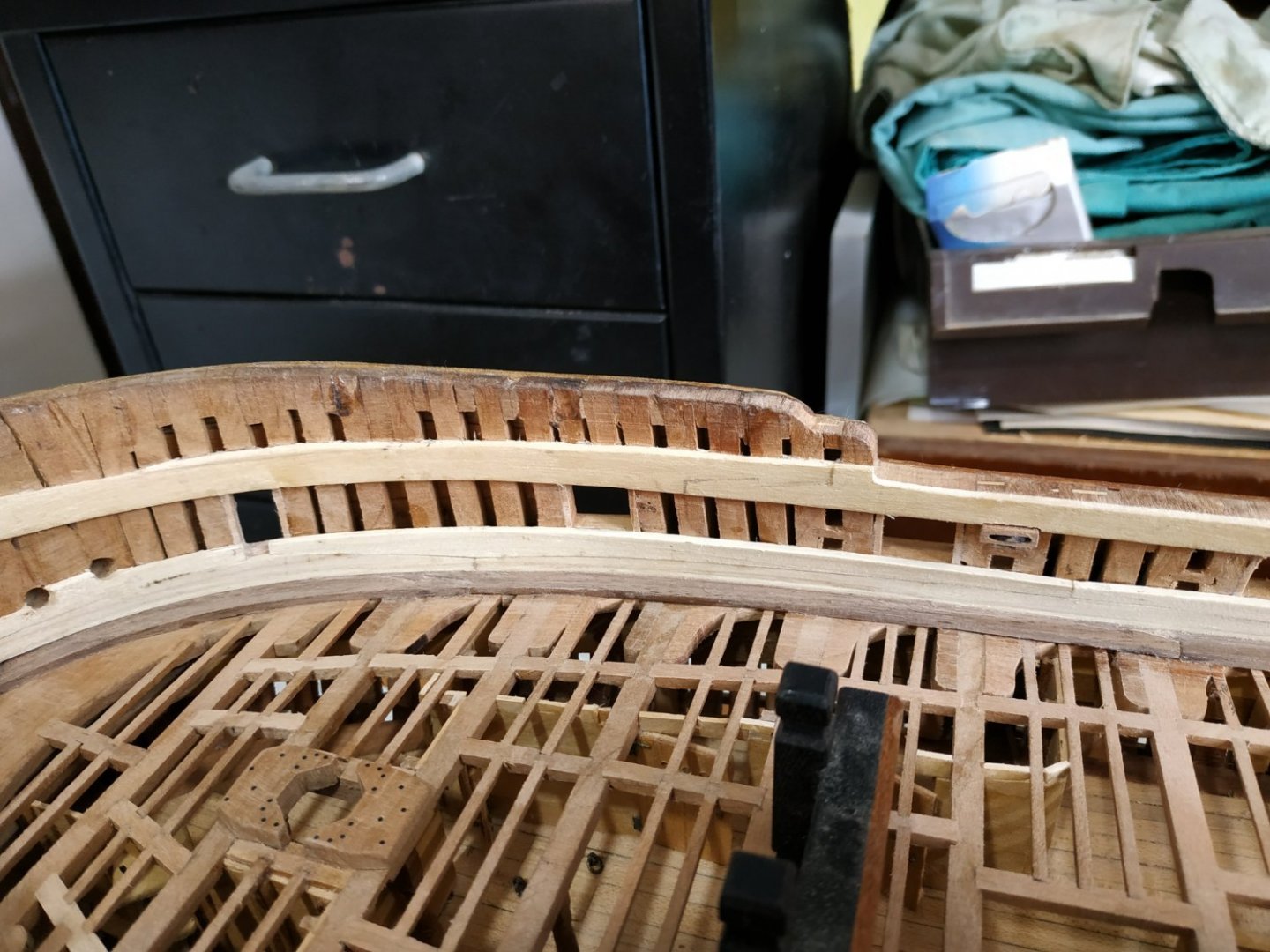
Upper Deck Waterway. Separating the Deck from the Hull Frames. Made width 6.36mm with thickness 2.13 at its outer ¼-(supposed to be “bearded back” 0.2mm-but will ignore),on which rests the Spirketting (inner hull strakes). The inner ⅔ is thinned to match the thickness of the planks -1.6mm. There is a slope of 1mm between the two thicknesses. Thought initially to use card but found that the printed cut outs matched pretty well and easier to trim the wood directly. Joints of hooked scarph make it easier to fit from stern ,forewards. The foremost pair of either side are separated by a small chock behind the stem. I intend to plank only one half if the deck and will omit the Spirketting on that side. I therefore masked this side by2.5mm while fitting the lower Spirketting to other. Final thinning after deck planks are fitted, but initial work using a Proxxon wand sander. (This is a wonderful tool but until now of limited use because the supplied adhesive sanding paper only lasts a matter of minutes. I found that now, even used cut-outs from self-adhesive 5in. Disks, work like magic and last) Anway, fitting a shortened sanding square with the last 1mm of the head masked (plastic decorative strip) allowed me to sand away most of the excessive thickness. (Alternatives such as milling on the curve, or making a bespoke scraper, seem more difficult)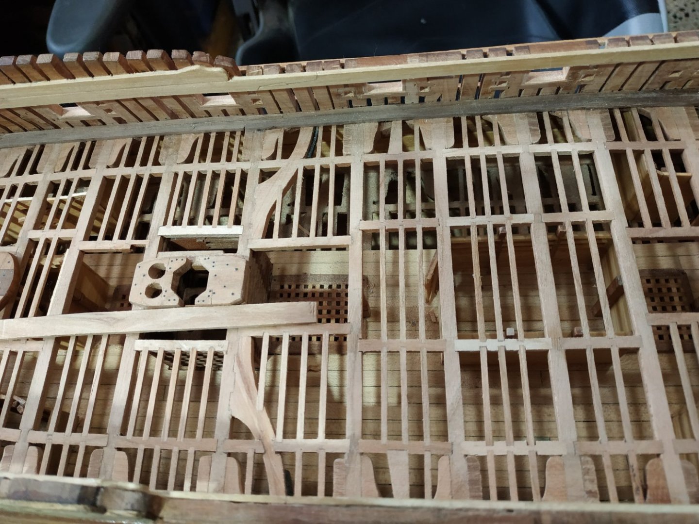


-
Swan-Class Sloop by Stuglo - FINISHED - 1:48
stuglo replied to stuglo's topic in - Build logs for subjects built 1751 - 1800
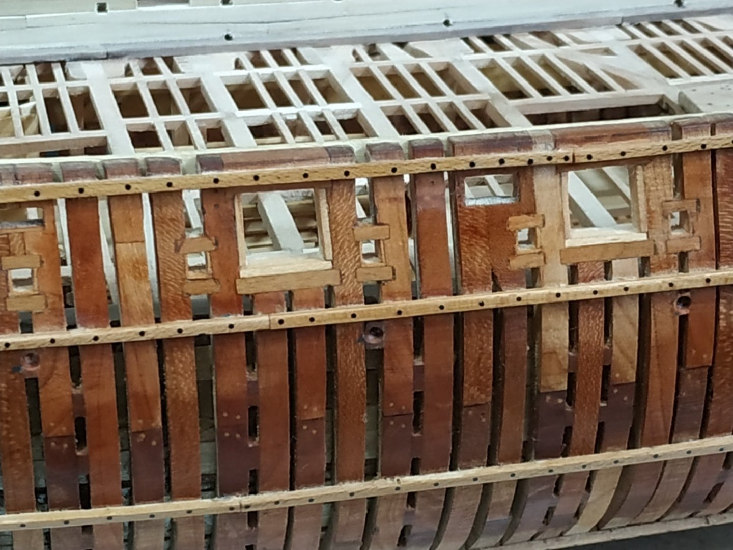
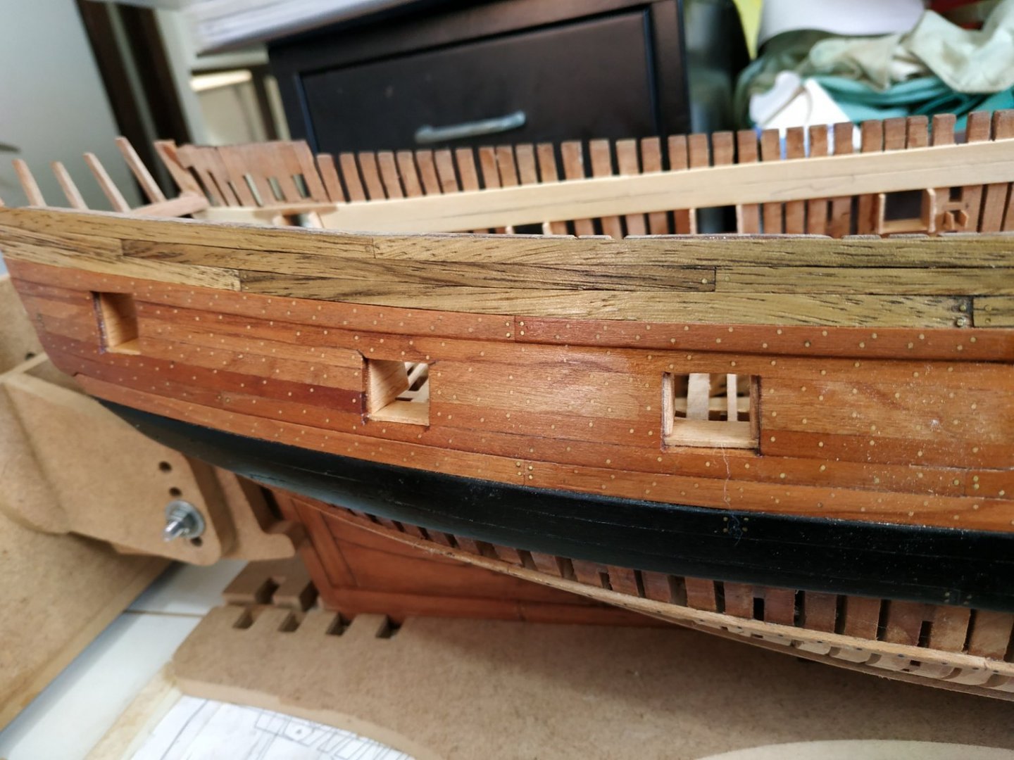
Upper Deck Port Stops. These are linings of port sills -form a rabbet for port lids. Lower stop and 2 sides. (Most kit models I made have an upper stop as well.The books I’ve checked show this or are not clear on the subject but I’ve come to trust TFFM.) They are 0.8mm thick. The sweep ports also have a similar lining but 0.4mm. The Stops are recessed to the inner edges of the planking and sill. The inner edges are flush to the frame . The outer edges are shaped to fit and the inner overlong to be sanded to shape after fitting and gluing. This seemed simple, but gave me no end of (self imposed) trouble. Because of slope and initial misunderstanding that they needed to include width of the Quikwork (internal planking) I made them very overlong. Also, I’d previously applied oil or poly to the Wales, and the port sills and wall didn’t “take” the PVA glue. Also I cut the wood for the side sills with the grain running up-down. When I came to sand the grossly overlong inner parts, they kept separating from the port wall and then a few broke. It took a while to realise that I must clean the walls with alcohol, narrow the pieces off the model before gluing again. I was too stupid and stubbon to remake them all again, so I persevered with what I had. This sanding of the inner hull also highlighted the deficiencies of some of these frames. To be corrected or hidden soon.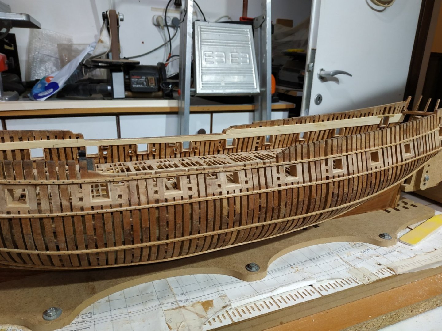

-
Swan-Class Sloop by Stuglo - FINISHED - 1:48
stuglo replied to stuglo's topic in - Build logs for subjects built 1751 - 1800
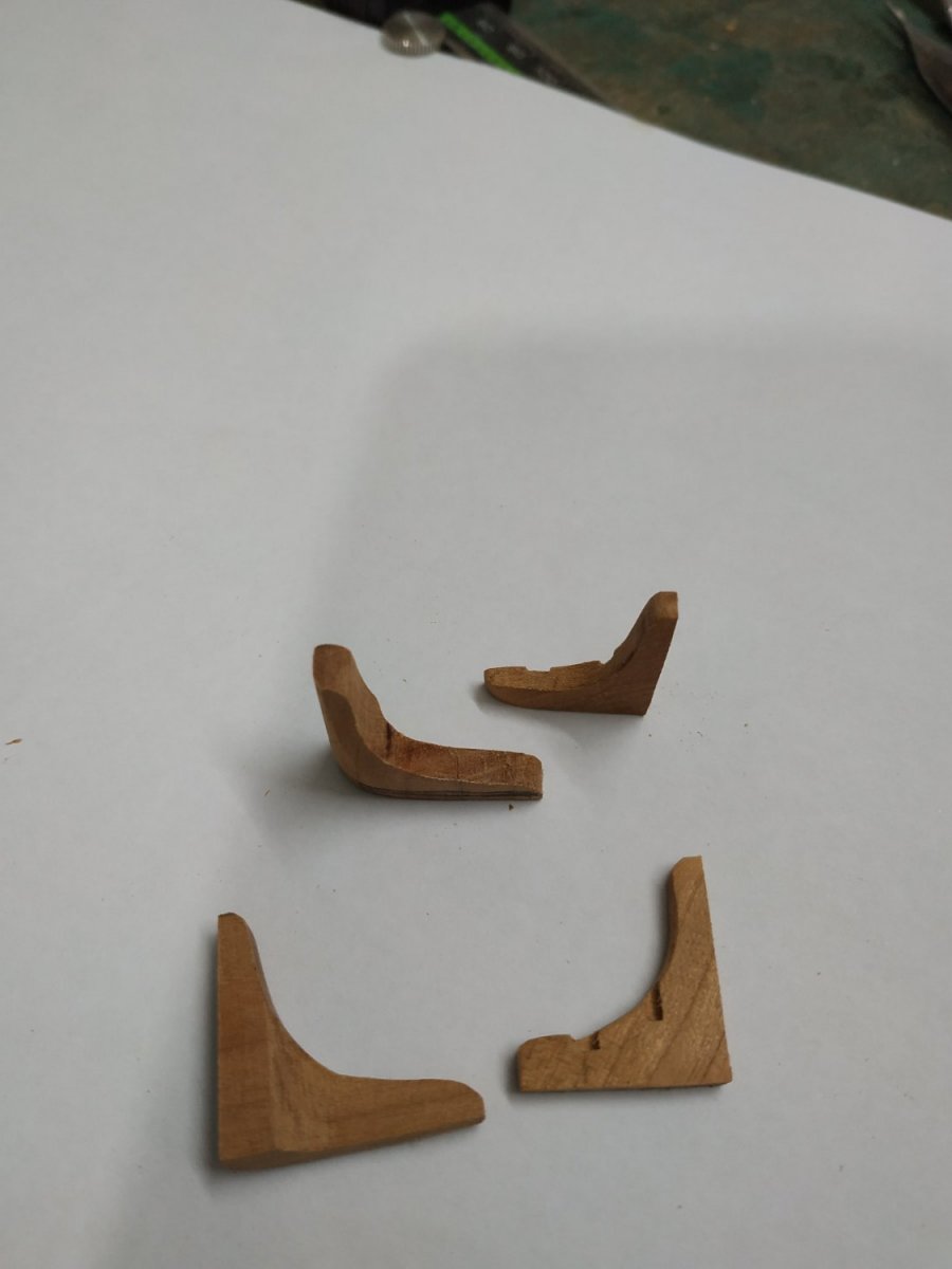
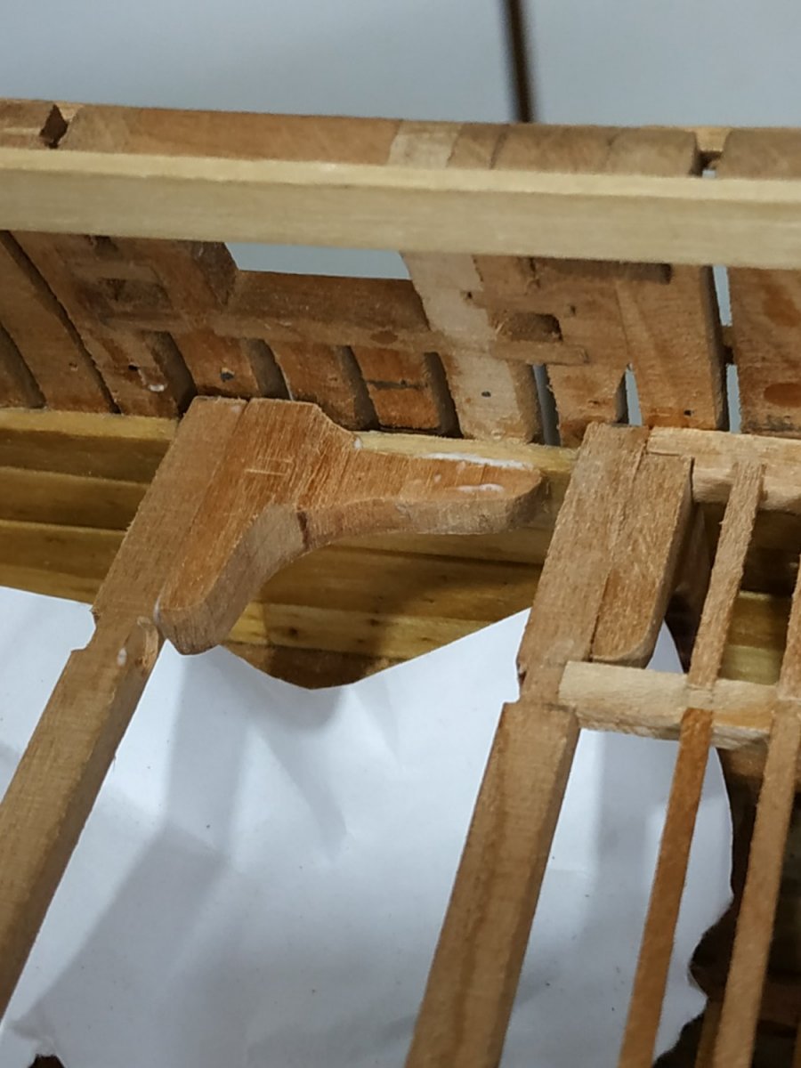
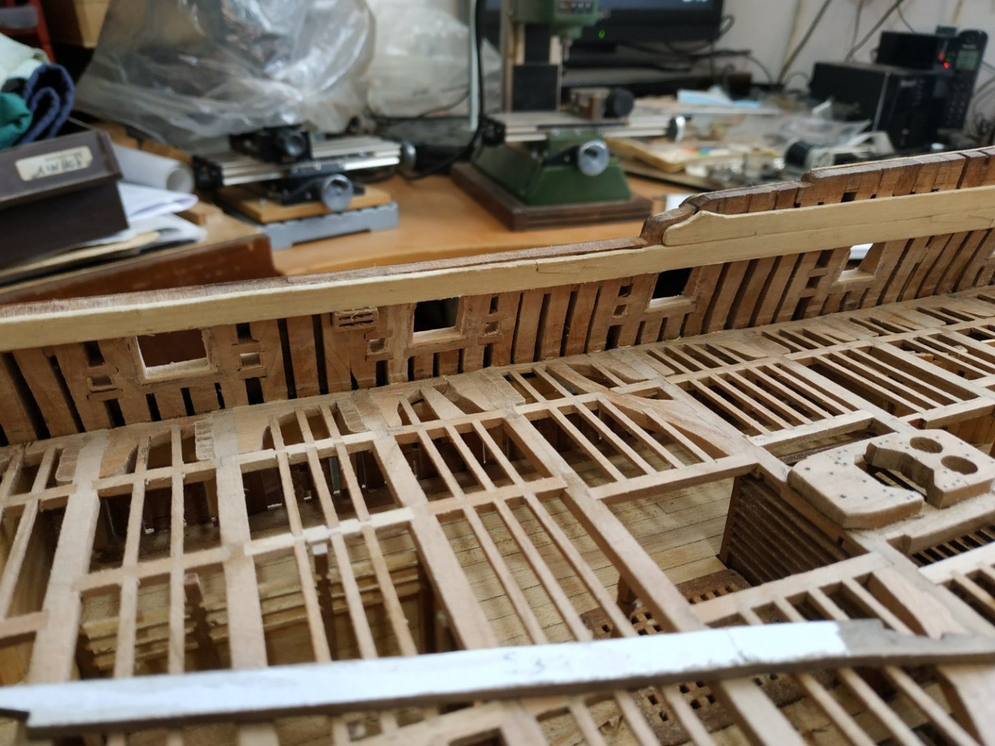
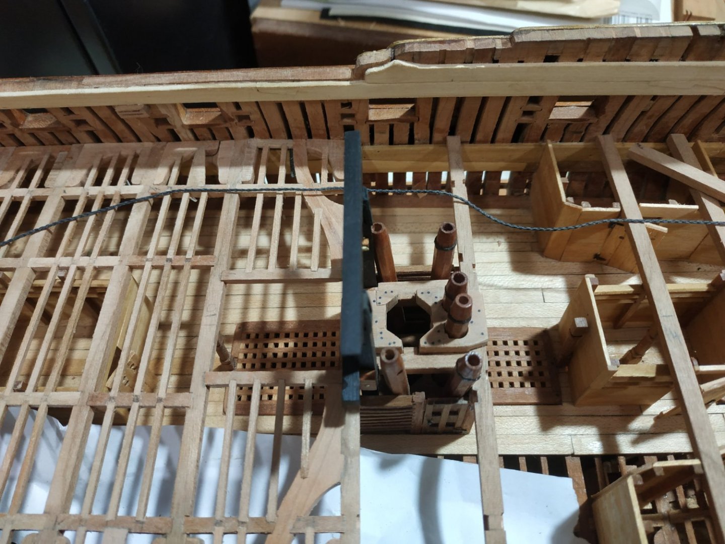
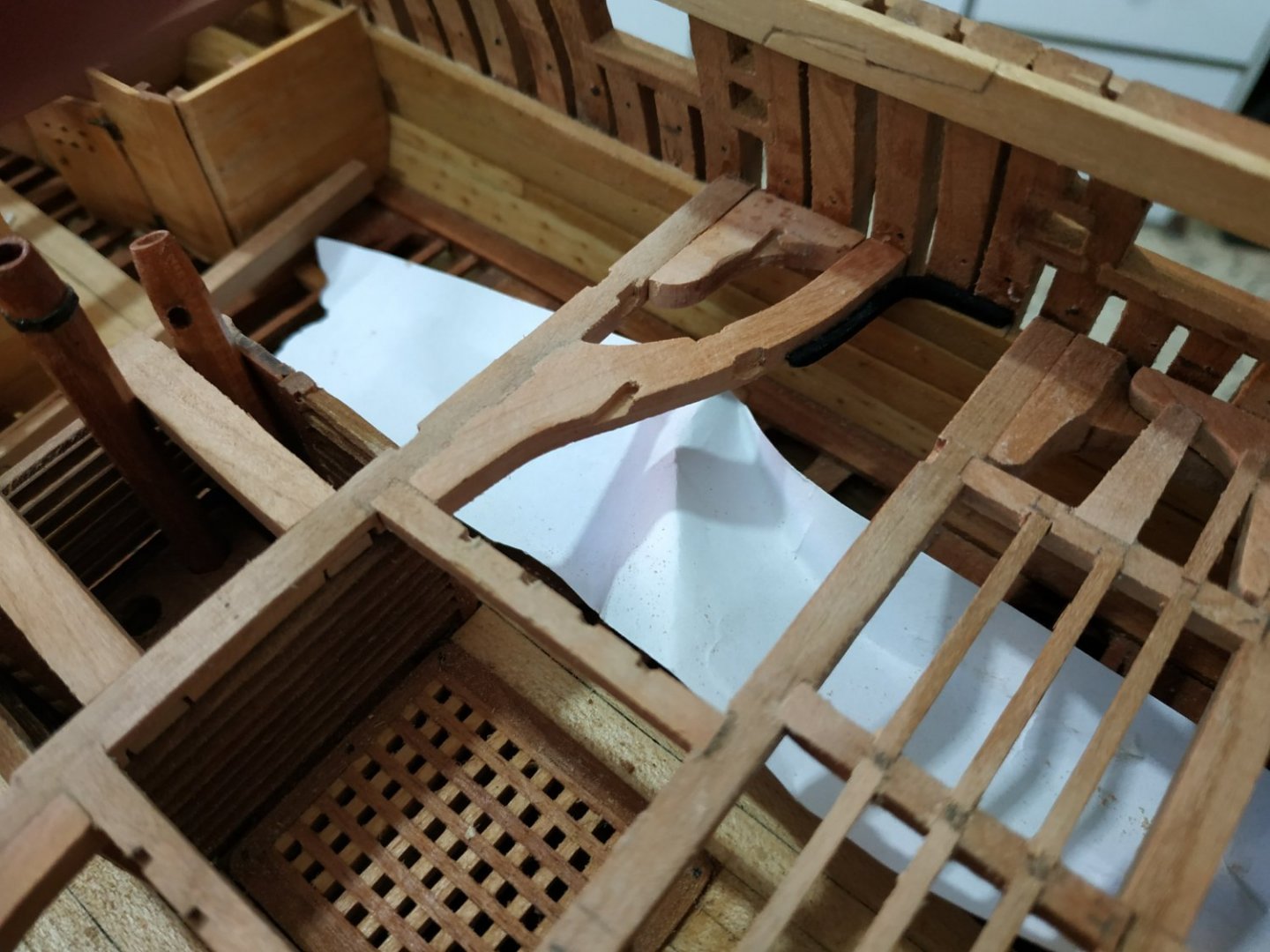
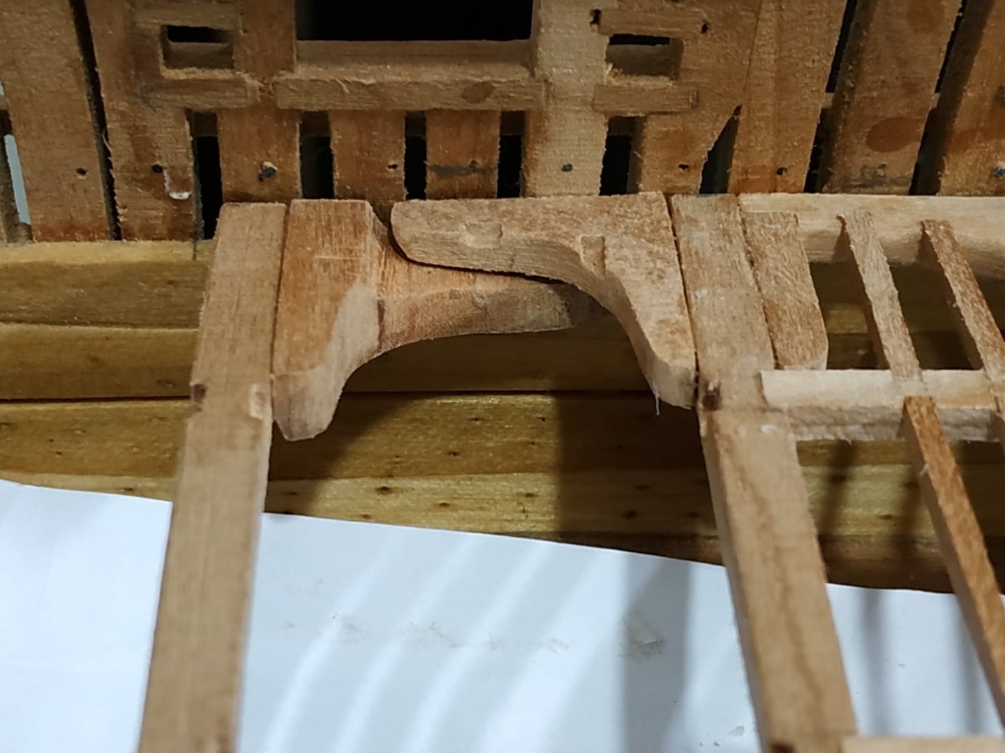
Bowsprit Step This will sit on fore aspect of #2 Upper Deck Beam, scores into the #3 Forecastle Beam and continues upward to form the Foretopsail Sheet Bitts. According to my plans, this is not a straight line- between the beams it is angled aftward (6deg) then vertically above. I could make each side out of one piece from a wide block, or in two stages, joining at level of the forecastle beam. Checking the Peter Goodwin book, this seems acceptable (and is certainly easier). These uprights are 4.24mm square and separated by 13.78mm A rough beam is made for the forecastle deck-3.45x2.65mm with a roundup equivalent to 3.18mm(over max width). The bases are notched with pieces at 6deg off the vertical with the mill. The upper end cut to reach the mid thickness of the forecastle beam, and notched at a similar angle. While in the mill, the acute tip milled to horizontal, to allow simple sitting of the vertical Bitt. The Step is separated by the Step Chock- 2 planks of 3.18mm thickness rabbeted together- and in turn rabbeted into the uprights-a 1.6 mill bit worked wonders. There is an additional rabbet to be made on the lower outer corners. This is for the Manger Planks. Discussed in a later chapter, but stated as level to height of the lower point of the Hawse Hole. The position and size of the Bowsprit mortise is left for later.

- 475 replies
-
- 10
-
-
Swan-Class Sloop by Stuglo - FINISHED - 1:48
stuglo replied to stuglo's topic in - Build logs for subjects built 1751 - 1800
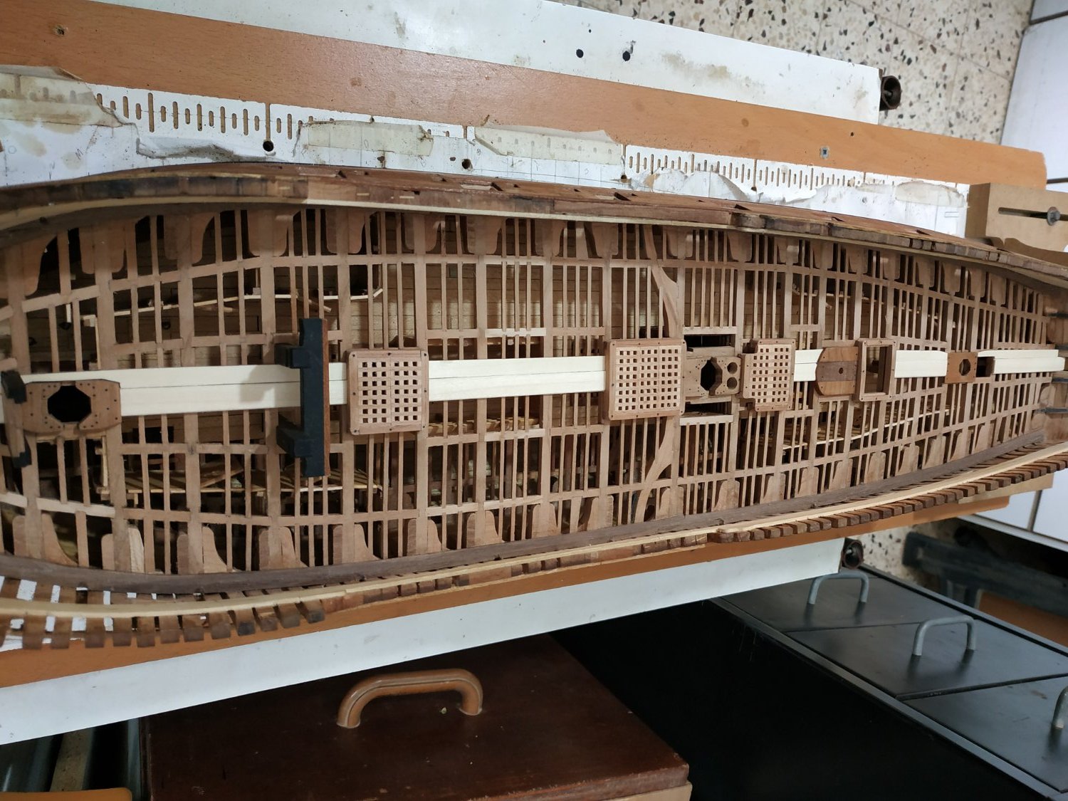
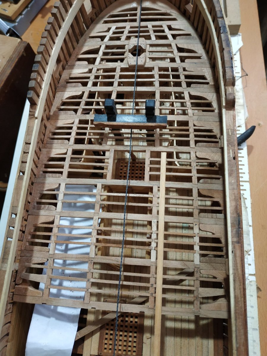
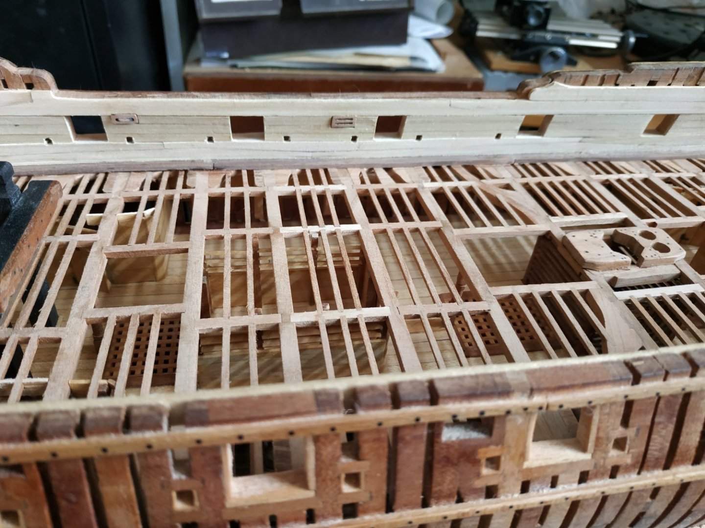
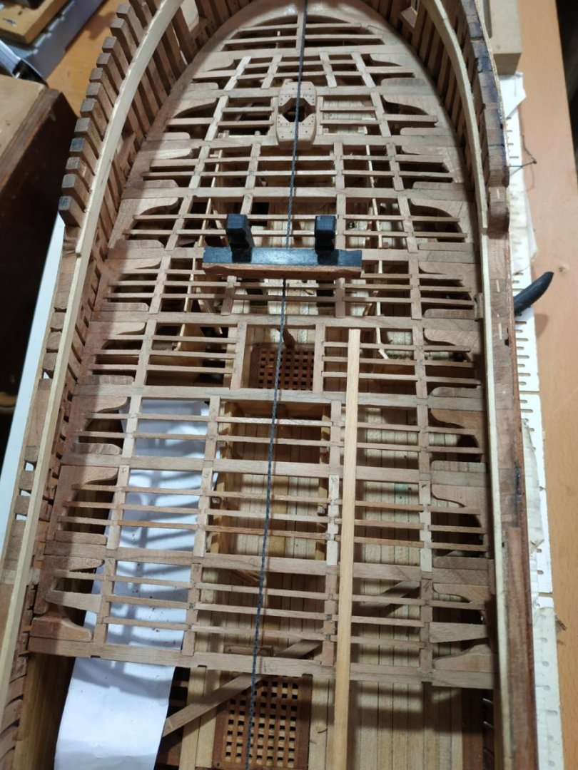
Upper Deck Beams cont. #19. Inner Carlings support a Scuttle, otherwise regular. #20. Note no Lodging Knees, but rather a Packing Piece to support a wedge shaped Ledge. #21. No Knees (? that's why short beams ha! ha!)-beams and Ledges directly onto Knee of Wing Transom #22. Onto W.T.Knee, outer Carling also onto WTK, no outer Ledges. Inner Carling mortised onto Wing Transom, with a single wedge shaped Ledge between them. Note temporary Forecastle Deck Beam #3 placed as marker for the Bowsprit Step, which sits onUpper Deck #2 and scored on F. Deck Beam. #3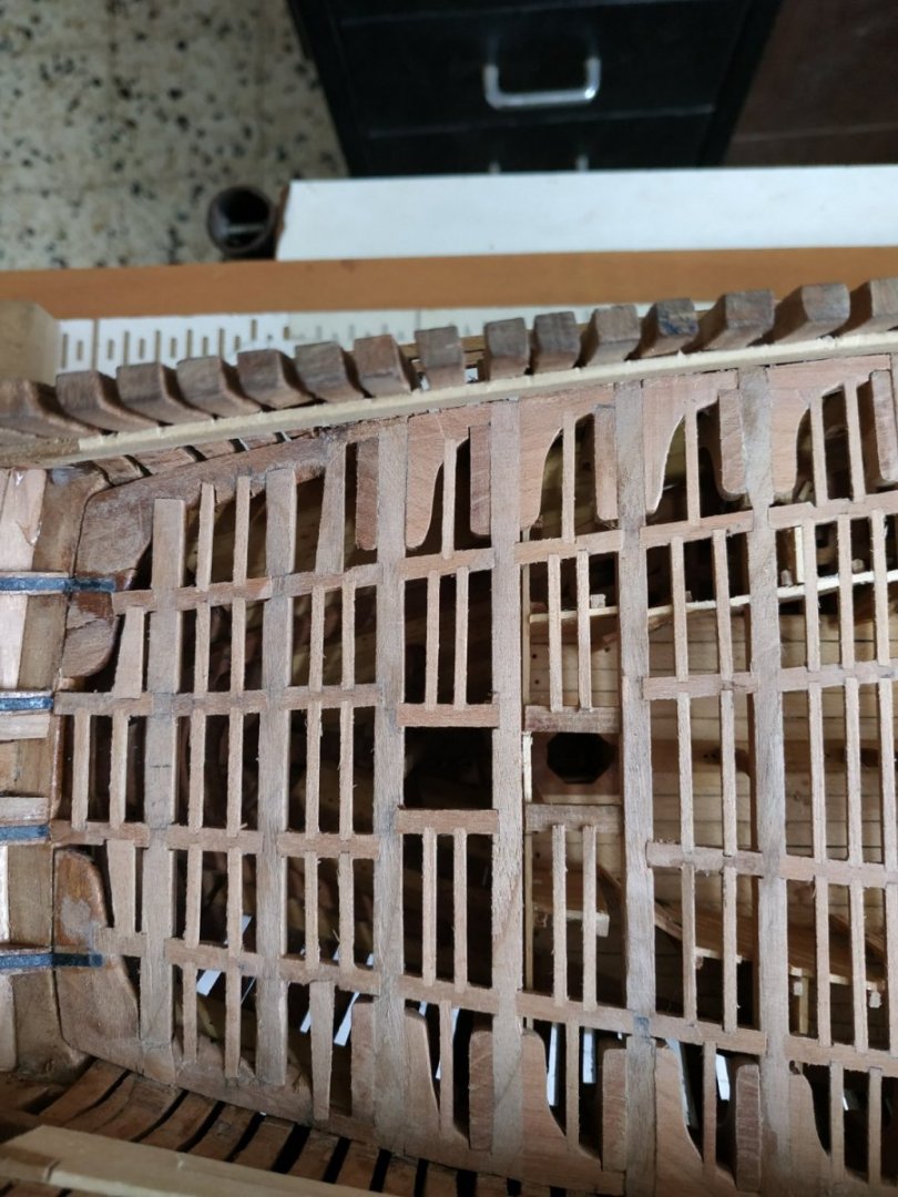
-
Swan-Class Sloop by Stuglo - FINISHED - 1:48
stuglo replied to stuglo's topic in - Build logs for subjects built 1751 - 1800
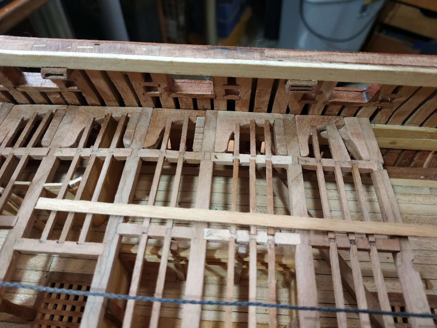
#17 Upper Deck Beam Supports the forward part of the Mizzen Mast Partner. This is of the type build for the Lower Deck. The supporting Carling are 3.98x2.65mm and half underlap the beams, so that their upper surface is 0.4mm below this level of the beams. I made the groove in the underside of the beam 1.7mm deep and the mortise of the Carling 1.3mm. The Carlings are set 11.0 mm apart. The Plank Partner is a single plank 2.12mm thick and 17.49nn wide. It is let down on the beams by 0.4mm so it sits on the Carlings also. The Ledges that fit these Carlings are left proud by 0.4 to compensate. Aft, the inner Carlings are in line with the support Carlings and therefore appear to sit on those Carlings which are mortised under the beam. The 3D rendition also seems to show this. Murphy’s Law is in effect. Either the spaces are narrowing or my fingers are getting fatter!!. In any case, fitting the various bits is getting more difficult-especially the Hanging Knees- and more pieces are being dropped and difficult to retrieve.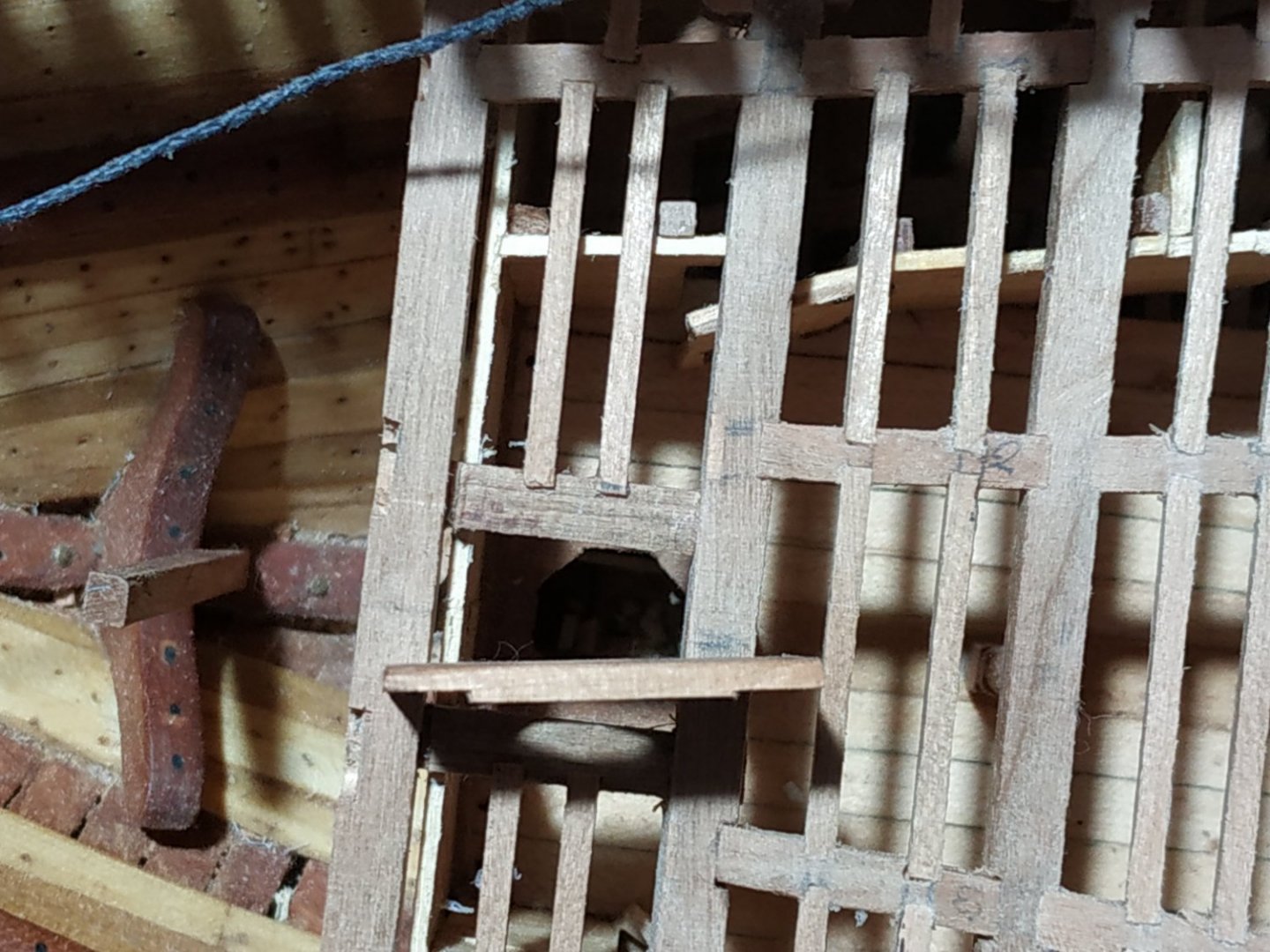

- 475 replies
-
- 10
-
-
Swan-Class Sloop by Stuglo - FINISHED - 1:48
stuglo replied to stuglo's topic in - Build logs for subjects built 1751 - 1800
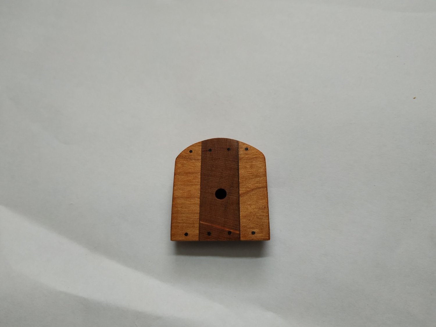
Capstan Step-Revisited I was unhappy with the first effort. The appearance of the wood and slightly off centre hole is apparent in the picture, so I remade it. (I also made the rabbet)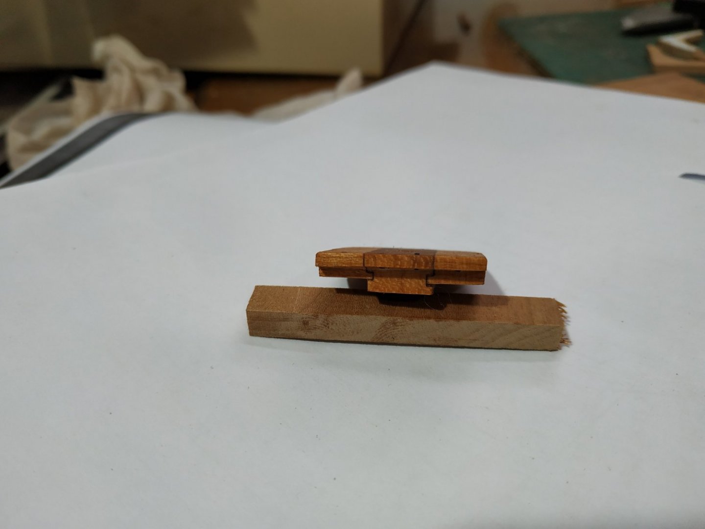

-
Swan-Class Sloop by Stuglo - FINISHED - 1:48
stuglo replied to stuglo's topic in - Build logs for subjects built 1751 - 1800
Upper Deck Beam #12 Note inner Carling needs adapting to take the Pin of the Main Jeer Bitt- a simple notch but as it is will be a weakened area/joint, I reinforced it with superglue to underside before fixing in position. Beams #13 and #14-regular, but inner Carling gap is narrower at 24mm to accommodate the Capstan Step- This is a solid plank between Beams 14 and 15. Size given as 10.07mm X7.42mm with a hole of 2.65mm to receive the Spindle of the Capstan. This hole DOES NOT go through the but to a depth suggested of +/- 2.5mm. The aft side is let down on Beam#15 by 3.71 so that a similar hight sits above the beam. Note this aft side only covers half the Beam width.The fore side is semicircular, similarly let down, but extends slightly foreward of the Beam it overlaps {#14) Along either side are Support Pieces, 7.95x5.3mm. These are also let down so their upper surfaces are in line with the Step. TFFM mentions them probably fitting into a Rabbet on the sides of the central plank, but having cut them to size already, I realized that to fit into the Rabbit would narrow them significantly. I fixed the Plank and Side pieces together and then milled the letting down as a unit. The underside area is rounded up to “Fay” with the Beams curvature. TFFM points out that the upper surface would have to be horizontal to allow the Capstan to turn- the illustration shows the Let Down of the sides where it sits on the Carlings, to be angled. I can’t see how this can be done unless the Let Down on Beams #14 ans 15 are different. I took an easy way out and, copying the angle between the beams, set the Step in the mill and “scimmed” off to the horizontal. It leaves the piece thinner, but the same above the beam level. ( Worth noting that in this, and some other things such as the depth of the spindle hole, the Sheer and Profile plans differ)

-
Swan-Class Sloop by Stuglo - FINISHED - 1:48
stuglo replied to stuglo's topic in - Build logs for subjects built 1751 - 1800
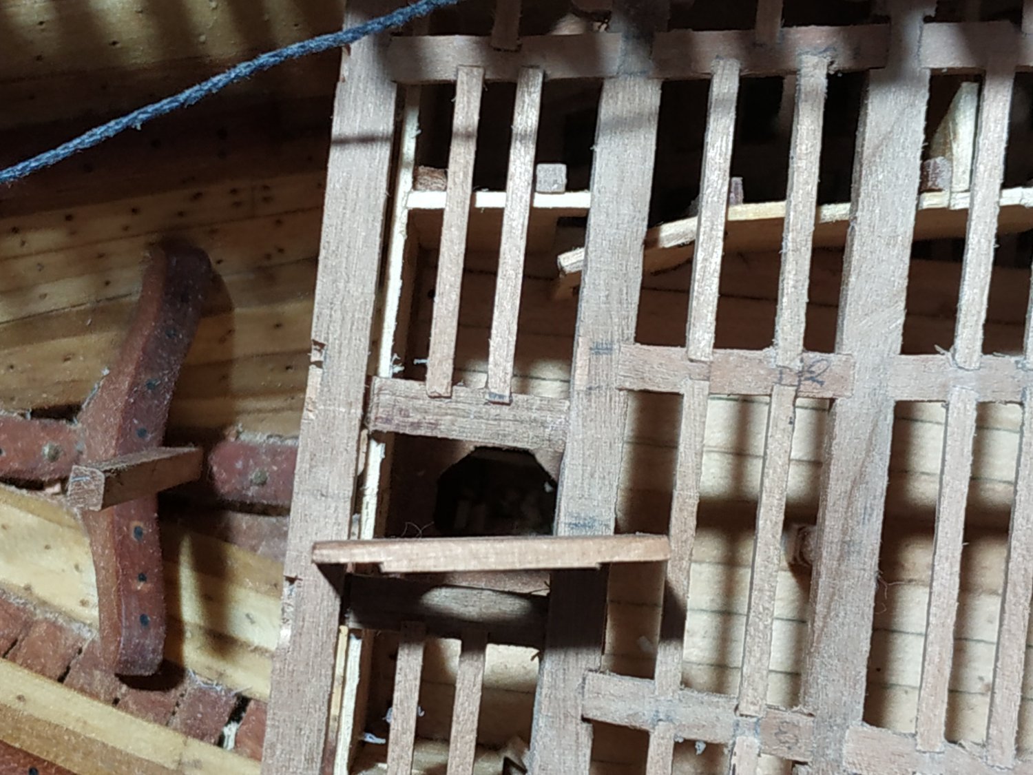
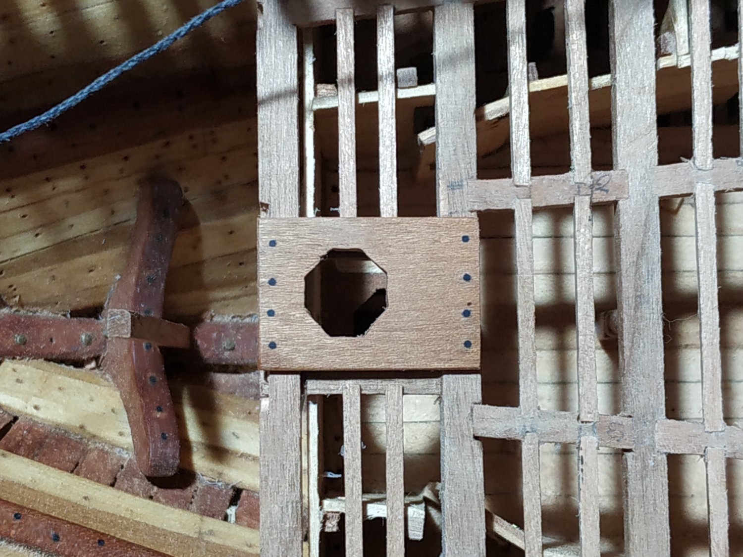
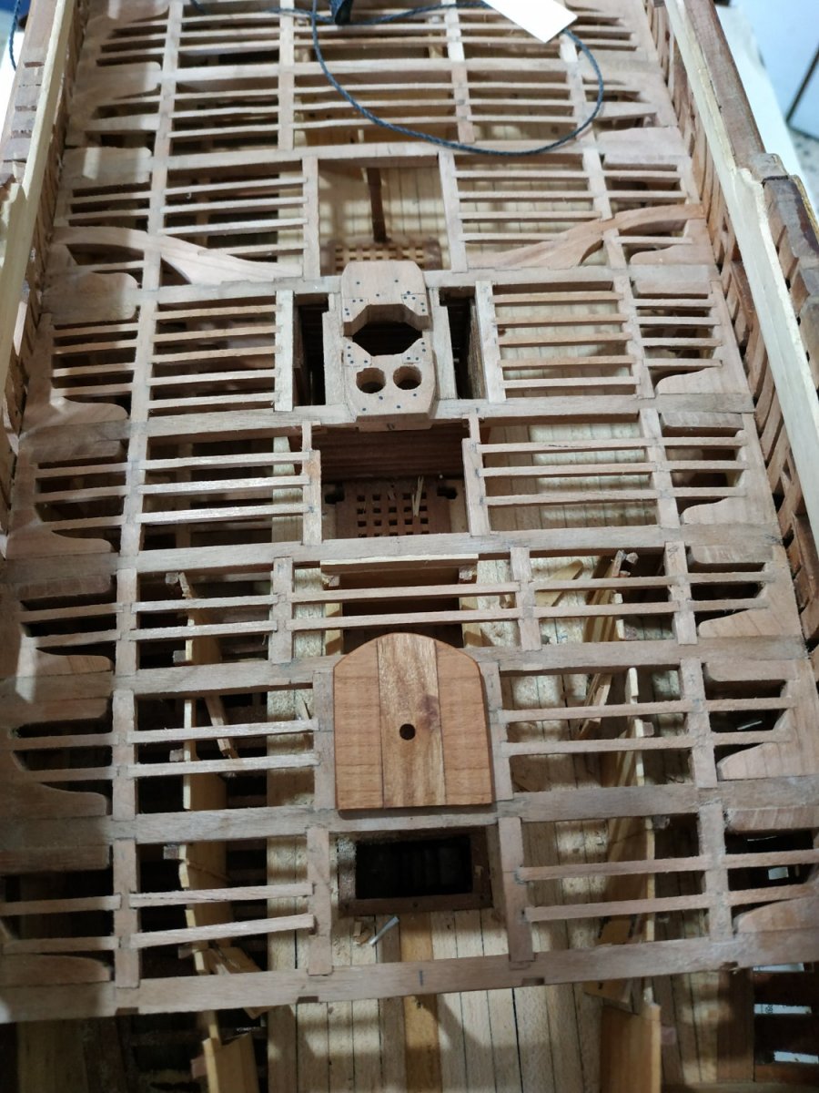
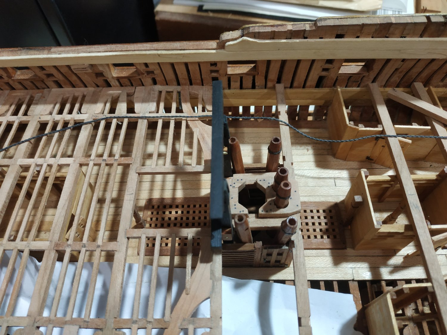
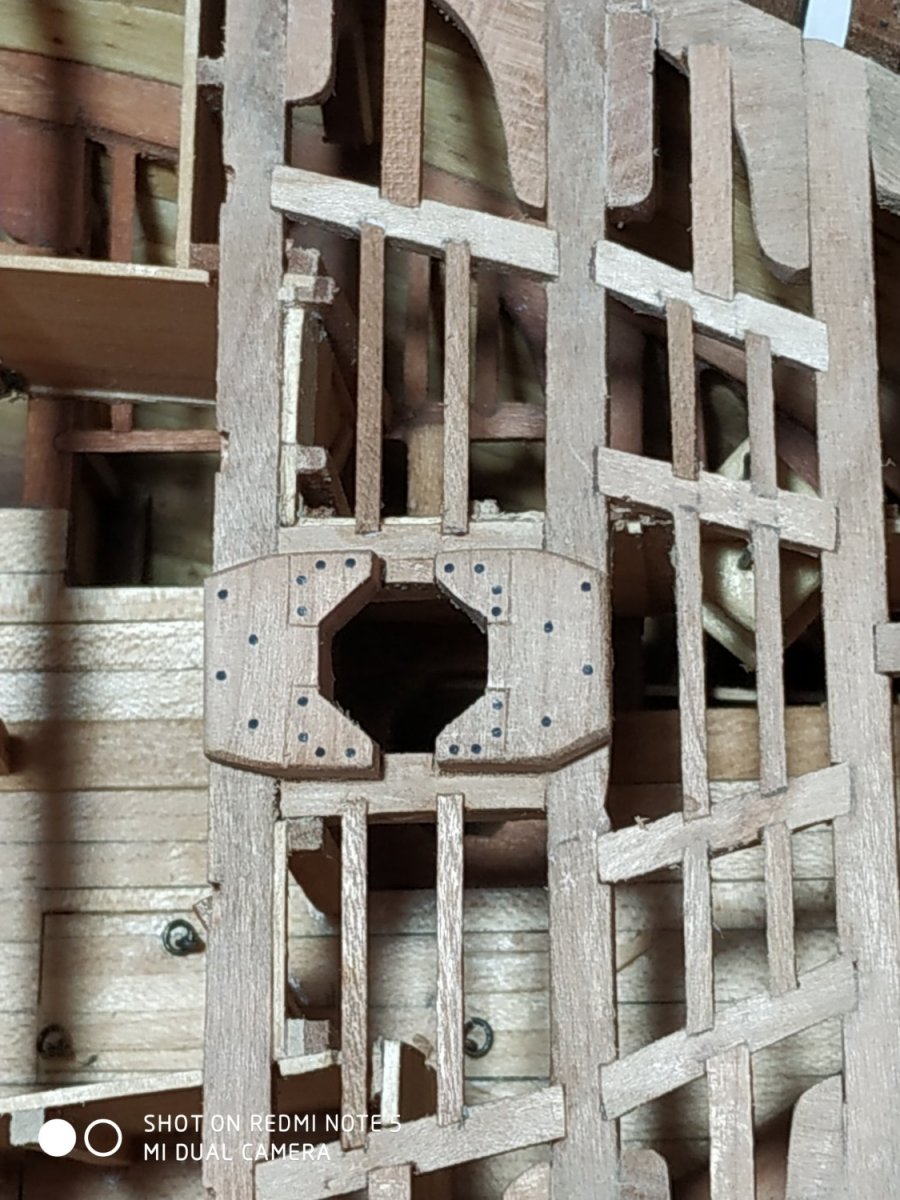
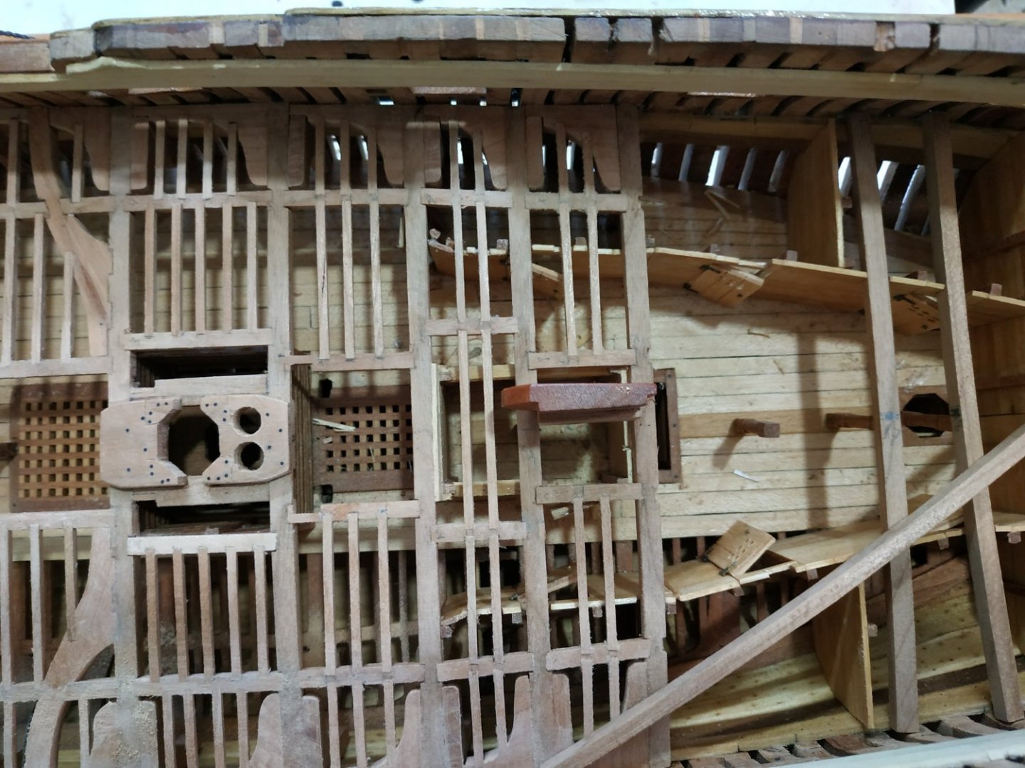
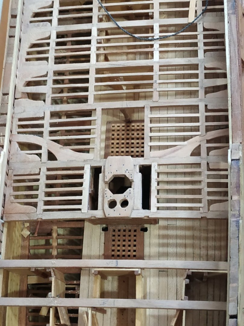
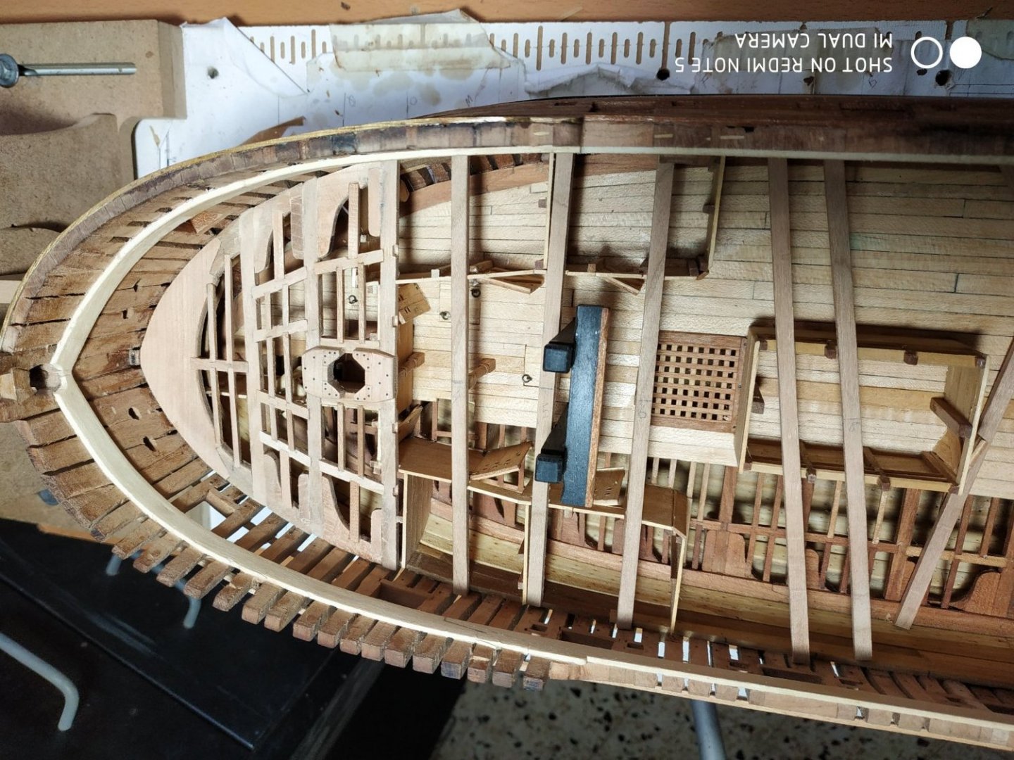
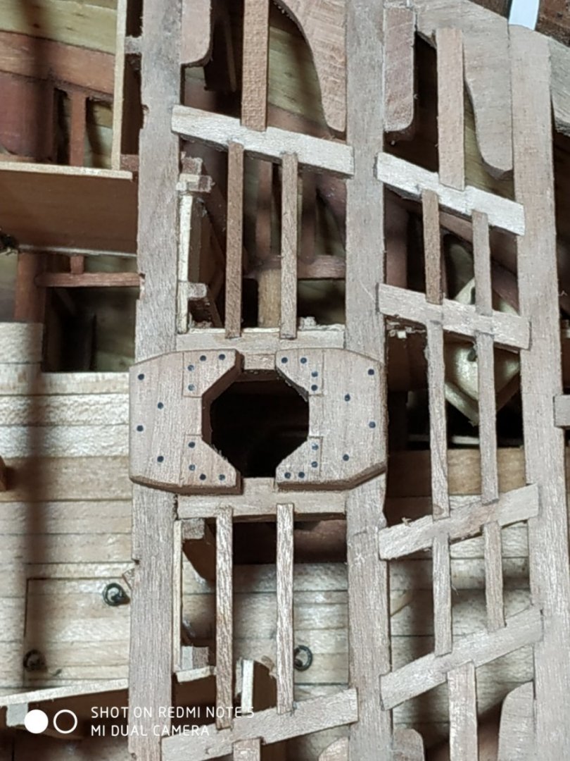
Upper Deck - Main Mast Partner Similar to foremart counterpart. The Carlings (6.36mm x 5.3mm deep) have already been made. They are set 14.84mm apart. The fore outer aspect needs trimming to allow for the Pins of the Main Topsail Bitt. The Carlings are half joined to #12 Beam which is cut underside by 2.12mm. The upper surface of the Carlings are partially recessed to allow the Mast Partner to sit on the beam after being let down by 2.12mm. The depth removed is 1.59mm (2.12-0.53) following the “footprint” of the Partners. The octagonal opening for the Pumps are filed out-but became more round than intended. NOTE -Hanging Knees, after #10 Beam, are now placed FORE between beams Also note that there are 4 ledges in outer group, and 5 for inner group.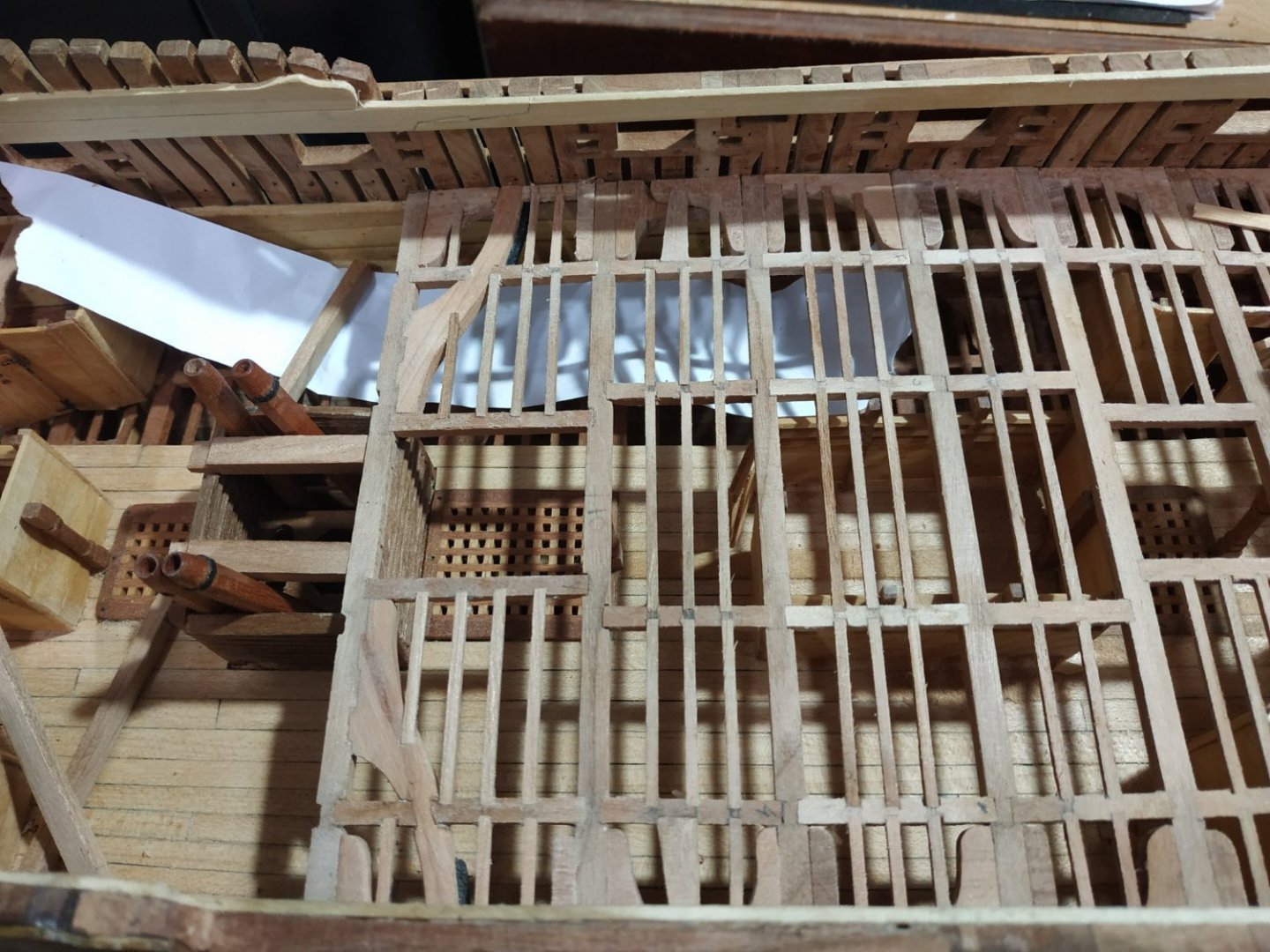
- 475 replies
-
- 13
-
-
Swan-Class Sloop by Stuglo - FINISHED - 1:48
stuglo replied to stuglo's topic in - Build logs for subjects built 1751 - 1800
Forgot a picture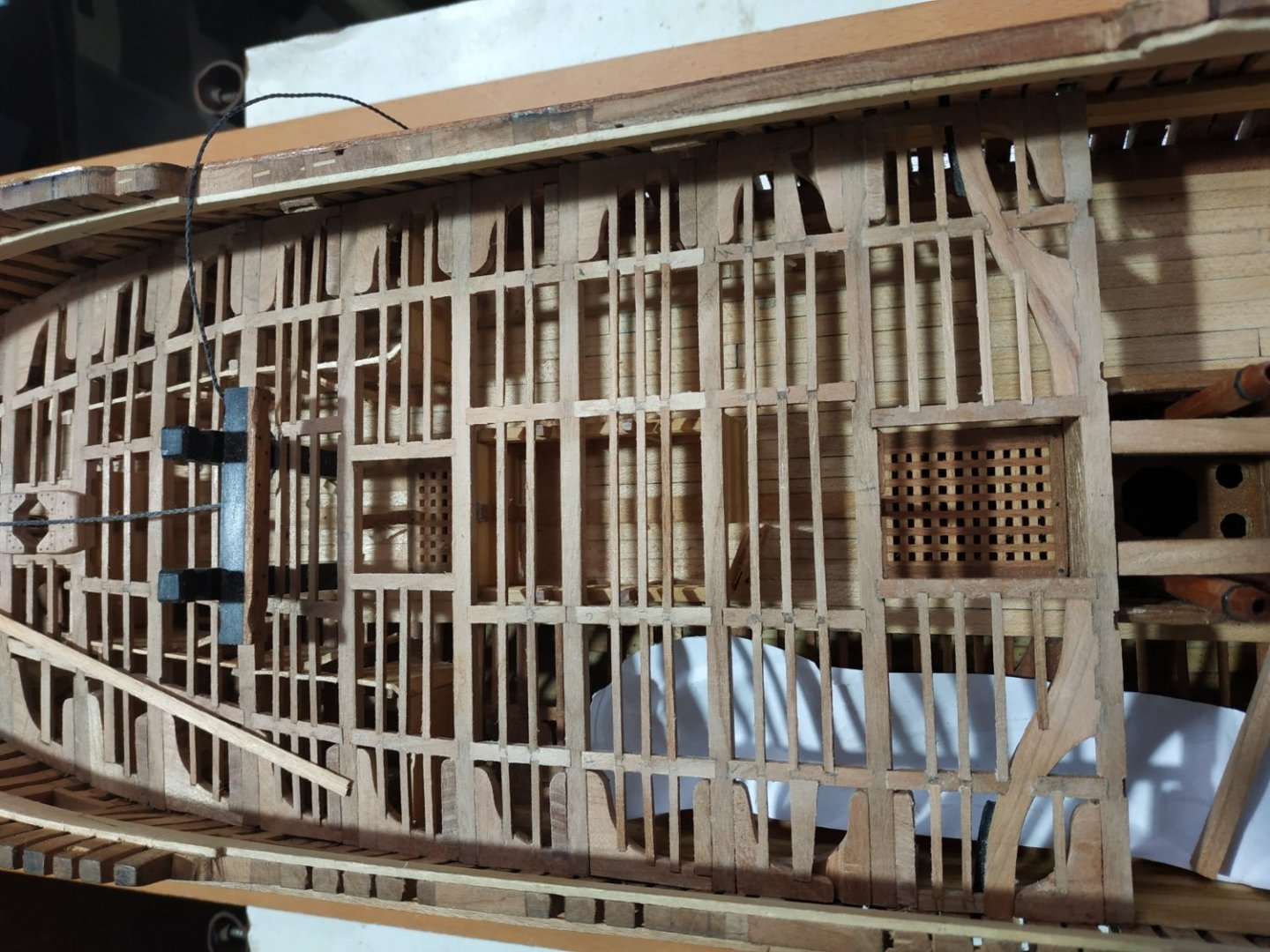
- 475 replies
-
- 10
-
-
Swan-Class Sloop by Stuglo - FINISHED - 1:48
stuglo replied to stuglo's topic in - Build logs for subjects built 1751 - 1800
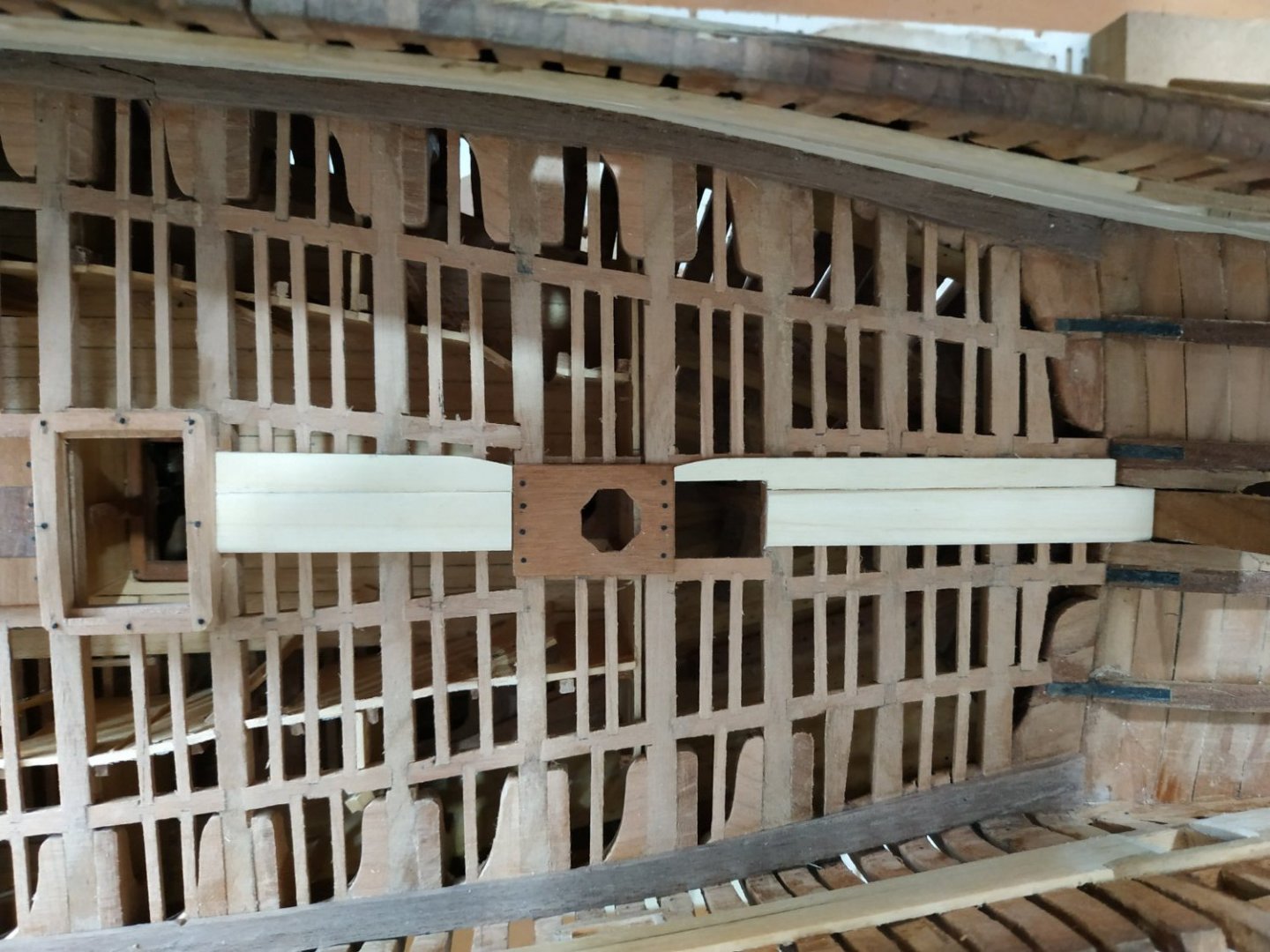
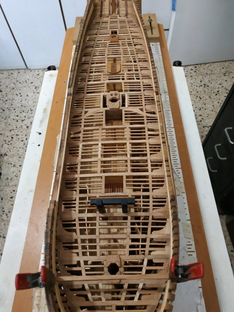
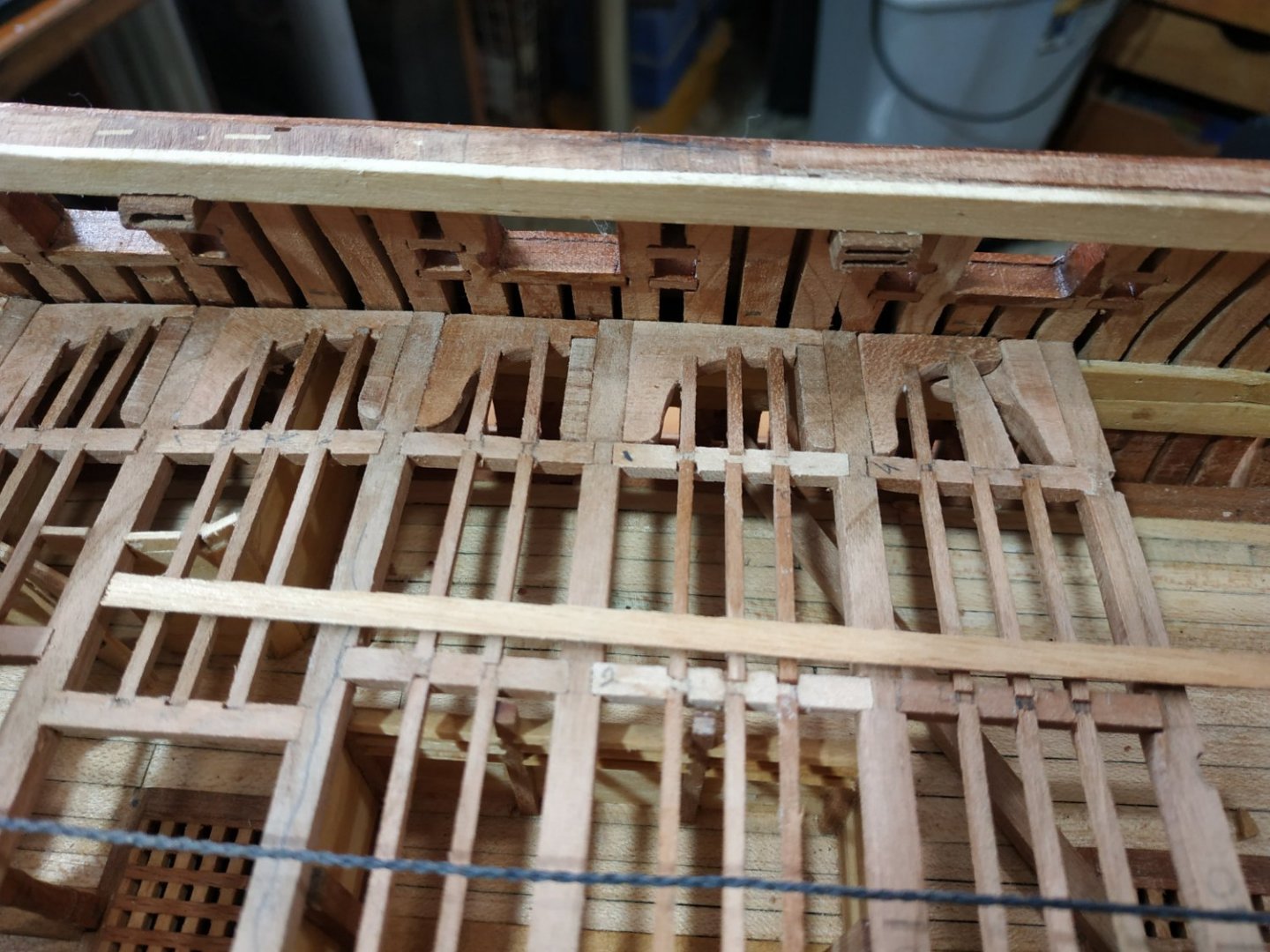
Upper Deck (cont.) #11 A wider gap between Beam with special structures (as lower deck). Firstly the Beam Arms. TFFM mentions that the Vulture has a paired arrangement and a triangular mast partner. My Atalanta plans show a similar arrangement, with what seems to be an overwrite on an erased area. This arrangement (like wings) is appealing to the eye, but I lack detail for the modified Main Mast Partner, so will go with TFFM plans. The Beam Arms, are 3.71mm thick, and are tabled 0.8mm into #11 Beam. The position of the fore inner and outer carlings similarly marked and checked that they line up with the carlings already fitted to foreward beams. The position of the Tabling notches are taken from the plan and marked, with reference to the inner Carling. Note the symmetry-teeth and gaps 5.83mm The aft outer Carling is inline, but the inner Carling is nearer the centre line, just outside the Pump Tubes. The Beam is turned over and the position of the Mast Partner Carlings marked so that they are 14.84mm apart. These Carlings are 6.36mm wide and 5.3mm deep. The Beam is undercut by 2.12 mm deep and 6.36mm wide. The various mortises and notches are milled Before fixing, I made the Partner Carlings-(6.36x5.3) with a mortise of 2.65mm to Half Joint to the Beam, leaving its level 0.53mm below the Beam. This was fortunate because I found that the upper lourve planks need trimming back. This done, The Beam is fixed.(note it sits on the fore and aft walls of pump room and there is no pillar) The Beam Arm is made with the cut-out TFFM pattern- the “teeth” position checked by offering up to the Beam. The outer arm trimmed to fit against the hull. The inner Carlin is dry fitted and the inner end of the Beam Arm is trimmed to fit. The Lodging Knee can now be cut to size, mortise for ledge marked and milled, and the part glued in place. While still dry fitted, the positions of Carlings and Ledges are marked. These are milled and the Beam Arm glued in place. The Hanging Knee, against the #10 Beam is made and fitted. An Iron lodging Knee, 2mm wide is made from a leather strip, attaching the Beam Arm to the Hull. A Packing Piece, 3.18 wide aX 1.6mmdeep, sits over the hull arm of the Iron, filling the gap between the Beam Arm and Hanging Knee. The Outer Carling is divided by the Beam Arm, dry fitted, ledges aligned, marked and milled before fixing.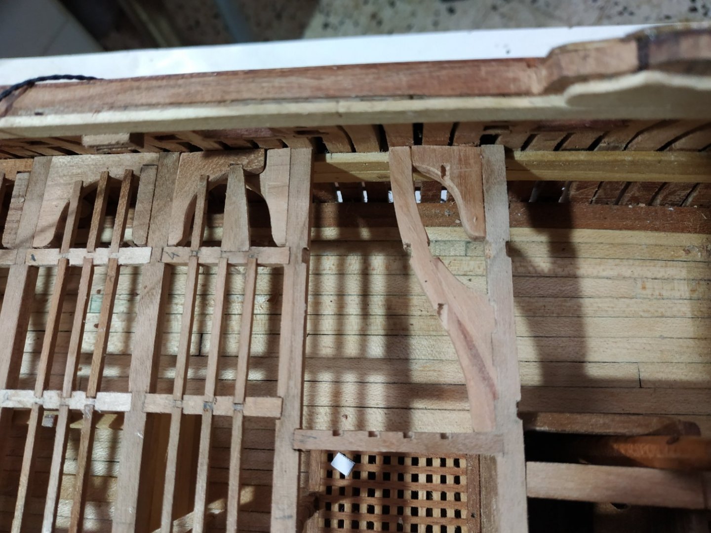

-
Swan-Class Sloop by Stuglo - FINISHED - 1:48
stuglo replied to stuglo's topic in - Build logs for subjects built 1751 - 1800
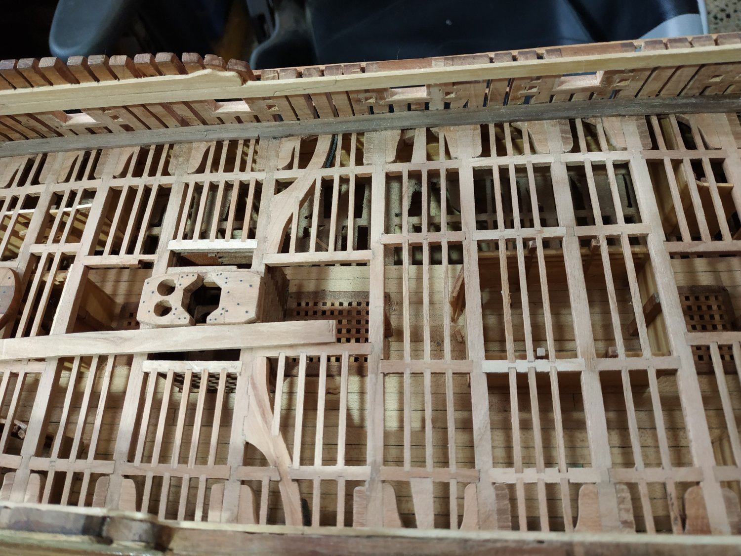
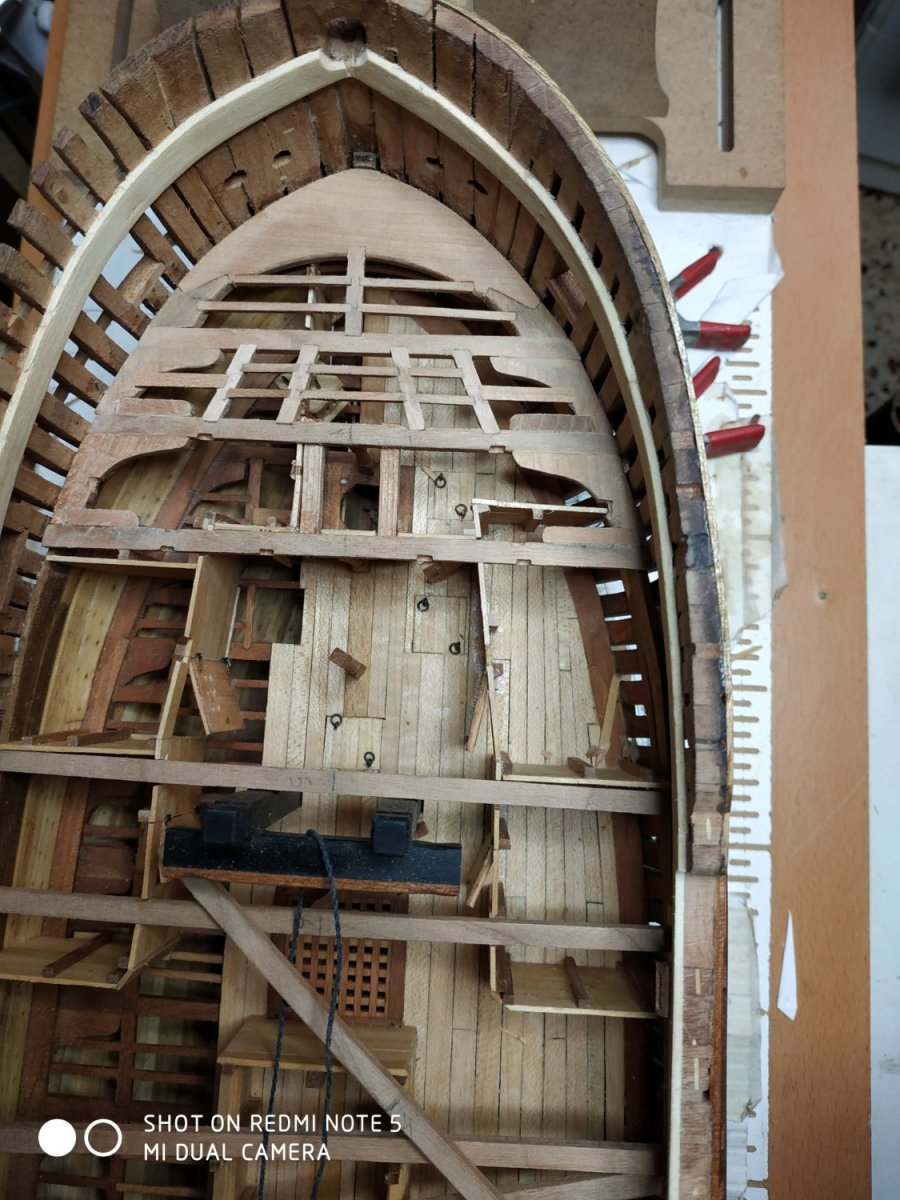
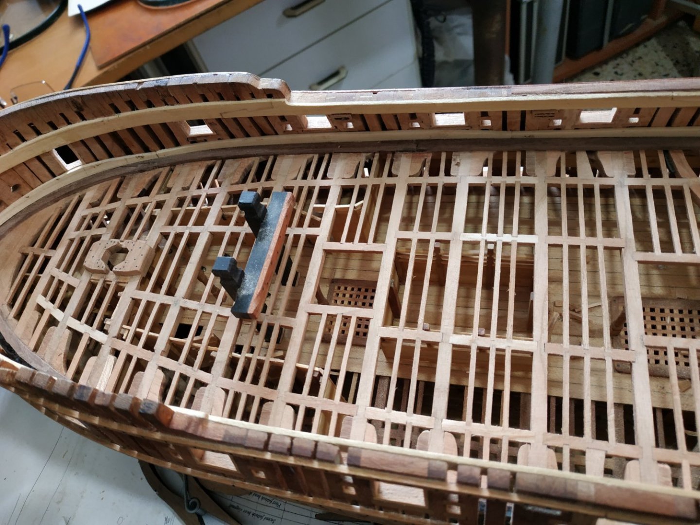
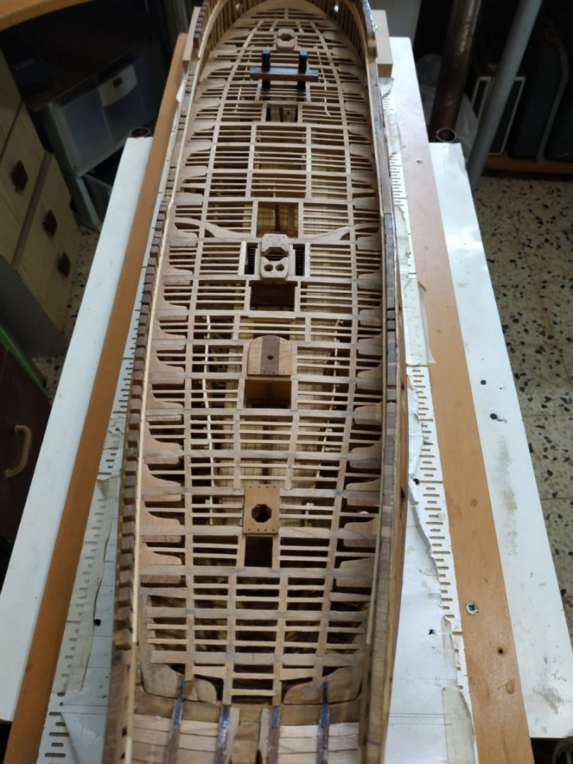
Upper Deck (cont.) Beams #5 to #10. (Paper strip to cover open lower deck to prevent bits dropping through) #5 The Beam sits in the mortises of the Riding Bitt Pin . Bulkhead walls removed and adapted to allow for the hanging knee. #6 and #7. Have the forehatch and therefore inner carlings closer together and without ledges. #8 and #9. Regular features #10. Aft, the mortise for the inboard Carling is not in line with those fore and aft , in order to form the support for the Main Hatch At the hull, fore to the beam, the normal arrangement changes to Opposed Lodging Knees ( similar to lower deck ). The aft of the pair sits beneath its partner and is fixed first. It is Let Down on the Clamp, to allow this. The aft ledge is mortised into the upper Knee, about midpoint between the Beams. It is wedge shaped, the narrower end toward the Knee.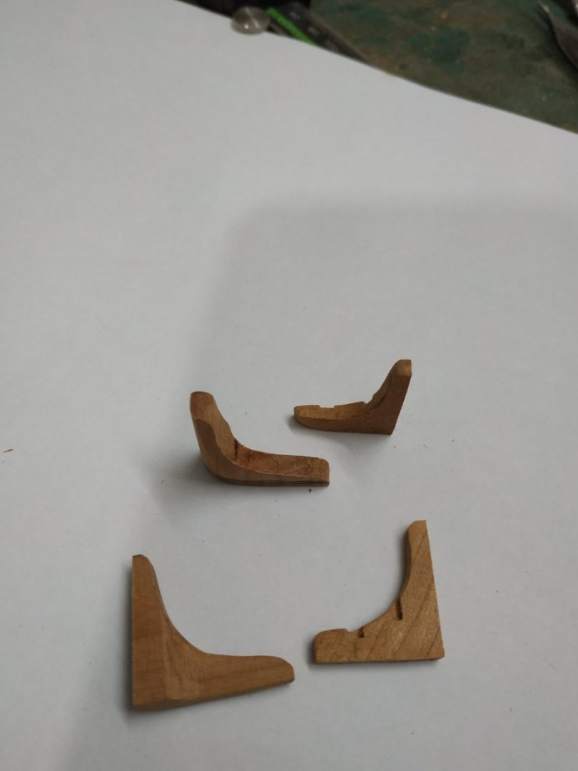

-
The amount to be cut out will vary, according to fit. Therefore must be left to the modeler rather than one size fits all. Just do it carefully- its an expensive item.
-
Swan-Class Sloop by Stuglo - FINISHED - 1:48
stuglo replied to stuglo's topic in - Build logs for subjects built 1751 - 1800
Carlings and Fore Mast Partners Revisited. My previous was incorrect-my understanding faulty, The 3D rendering is good but lacks measurements. My geriatric dyslexia required (again) a brainwave on awakening at 3 am and attending to the problem. (Unfortunately, the Bosun objects to my use of anything other than a pencil and paper-definitely no actual building at this hour.) Anyway, the problem is the relationships between the Carlings, the Beams and the Chocks. Most of the information is there (TFFM) spread over several pages. (I will use the actual “inches” rather than the metric scale for simplicity.) Firstly, the the Carlings are 10in deep.The ends sit under the beams #2and#3, forming a Half Joint. The Beam (7ins deep)is scored-undercut, by 4 ins. The Carling is mortised,so as to leave its lower surface 1in below the lower surface of the beam- That means 5ins removed. Also it means that the upper surface of the Carling is 1in below the upper surface of the beam. The Chocks, a pair fore and aft, sit on the Beams and the Carlings.(The Chocks are formed by a large Cross Chuck and a smaller Corner Chuck. Together they form a horseshoe shape. For simplicity, I made them as one piece. The Chocks are nominally 10in thick and let down on the beam so a depth of 6 ins are proud, i.e. 4in removed. They also sit on the inner aspect of the Carlings. These are let down by 3ins (4in-1in). As there is a gap between the arms of the fore and aft pair of corner Chocks, this area is NOT let down, leaving the full height of the carling, between them. The outer (hull) side also remains at full depth-leaving a pattern like a “T” with a short “leg”. Only NOW I begin to be able to interpret the drawings in TFFM To be honest, it was only later that I realised this,after the Chocks were fitted. I therefore “faked” it by adding this”T”. Couldn’t face another remake. I’ll do it properly for the other Mast Partners. Note- as these Carlings sit lower, the ledges are left 1in proud.
- 475 replies
-
- 12
-
-
Swan-Class Sloop by Stuglo - FINISHED - 1:48
stuglo replied to stuglo's topic in - Build logs for subjects built 1751 - 1800
Please ignore the stuff about the carlings for the foremast partners-its completely wrong. Corrections with next post.