stuglo
-
Posts
707 -
Joined
-
Last visited
Content Type
Profiles
Forums
Gallery
Events
Everything posted by stuglo
-
Swan-Class Sloop by Stuglo - FINISHED - 1:48
stuglo replied to stuglo's topic in - Build logs for subjects built 1751 - 1800
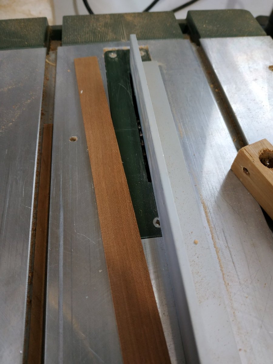
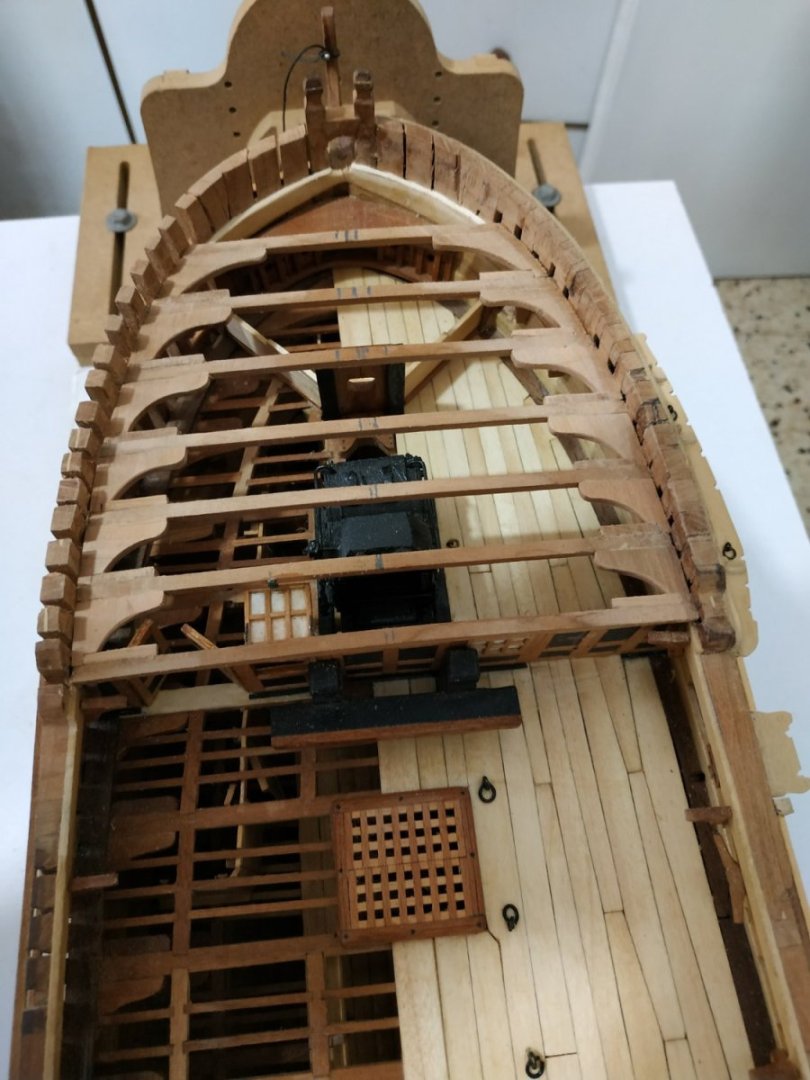
Forecastle Deck Beams Already made so as to build and fix the Bulkhead/ To re cap- 3.5x2.65 mm rounding up 3.18 over 14 cm length. They are lighter as they carry less load and similarly have less reinforcement with Carlings and Ledges. MISTAKES: I forgot to pre-score the Beams for these, but managed with chisel after fitting. More importantly, I should have noted the requirements of the Cathead (underscoring Beam #2, the seating of the Partners and the Half Hook. I realised this only after the Knees and Ledges were fitted. I didn’t want to undo everything, so the required work was less clean and accurate than if I did it off-model with the mill. The #7 Beam is special to form a rabbet for the planking. Instead of an overlarge section, for the model, it is constructed in 3 parts: the normal beam, a protruding lip and a molding at the join between them. I made the “lip” with a strip 3.3 mm wide, and cut a groove with the lowered blade of the table saw to allow the planks,1.33mm thick, to lie flush. The aft of the lip is chamfered. Between the overhang of the lip , and the beam, a molding of approx. 1.8x1.0mm Lodging and Hanging Knees. Thickness 2.4mm. The arm of the former is 19, the leg of the latter is 17.5 (approx) The 3D- rendering shows an S shaped Hanging Knee where there is a port, but I couldn't remember doing this before, nor could I see reference in this vol. or in Book 1. The leg, if left straight, was only shortened by a1/4- should have been strong enough in practice. Can anyone provide information? (Please)

-
From your picture you seem a youngster, so maybe time is not a problem. If however you have the space and money and wish to save time, may I suggest in addition to the usual:- Band saw Spindle sander Hand held band sander NOT by any means essential, but when used carefully, reduced hours of work to minutes and increase, at least in my case, the pleasure of building 'scratch'
-
Thank you for sharing
- 1 reply
-
- 3
-

-
Swan-Class Sloop by Stuglo - FINISHED - 1:48
stuglo replied to stuglo's topic in - Build logs for subjects built 1751 - 1800
Lower Counter Rail At the junction of the Lower and Upper Counters. 2.39x1.6mm molding, profile similar to the Truck Molding (but thinner). The boxwood took the compound curves easily without special shaping to allow it to lie. It is noted that the lower surface sits 0.53mm below the knuckle. Upper Counter Rail The upper edge is level with the knuckle of the upper counter It is slightly less deep at 2.12mm but with a similar profile as the Lower C.R.
-
Swan-Class Sloop by Stuglo - FINISHED - 1:48
stuglo replied to stuglo's topic in - Build logs for subjects built 1751 - 1800
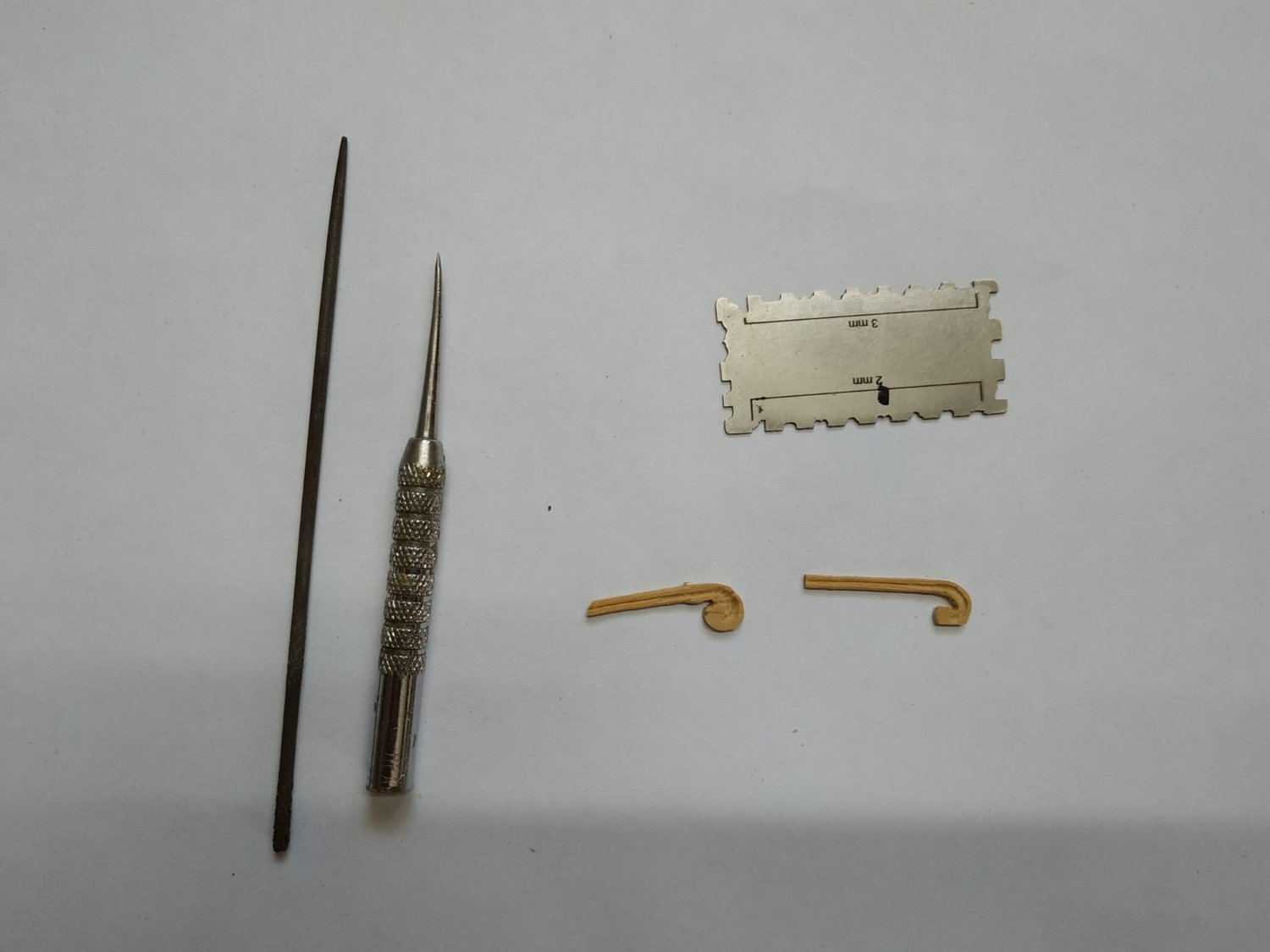
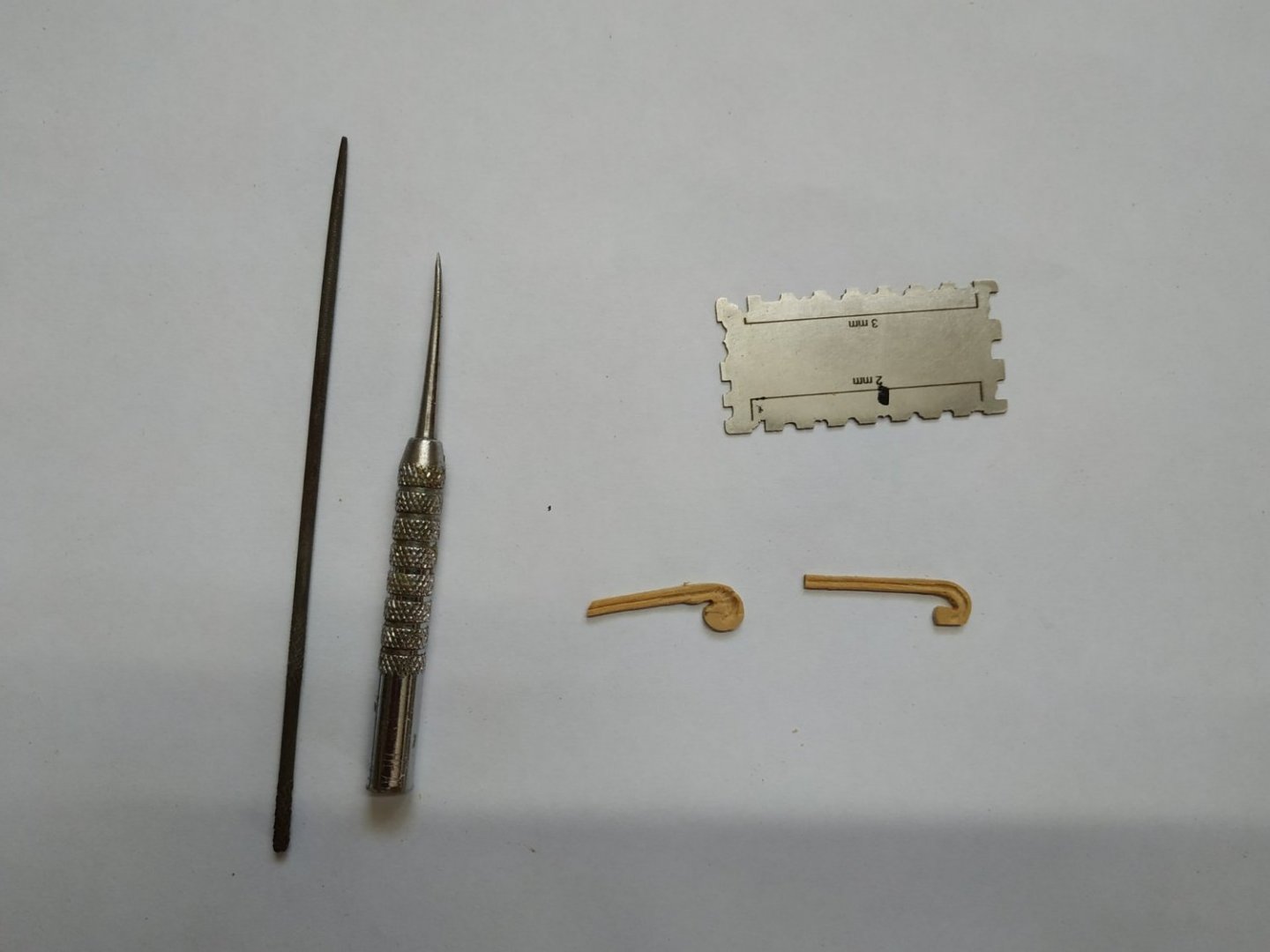
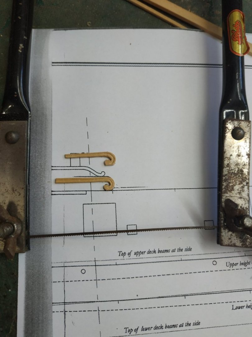
The Drift Rail. So-called because where it changes level it drifts. At the waist, where it is interrupted, it finishes in a scroll expansion called a Hance. The molding profile is 2.12x1.3mm, the width of the scroll is 3 times the latter number. These Hances seem to vary slightly from drawings to models. They need a steady hand and patience . I lack both. I found that anything electric was difficult to control and made a mess. I used a sharp metal point, 2mm files and sandpaper. I was later inspired by seeing my jeweler friend using an old small hacksaw . I’ve uploaded pictures of several tries and am not sure if I won't revisit again.
-
Swan-Class Sloop by Stuglo - FINISHED - 1:48
stuglo replied to stuglo's topic in - Build logs for subjects built 1751 - 1800
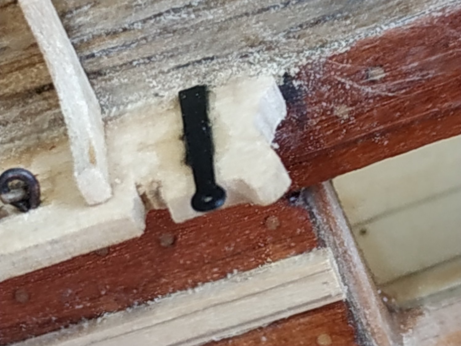
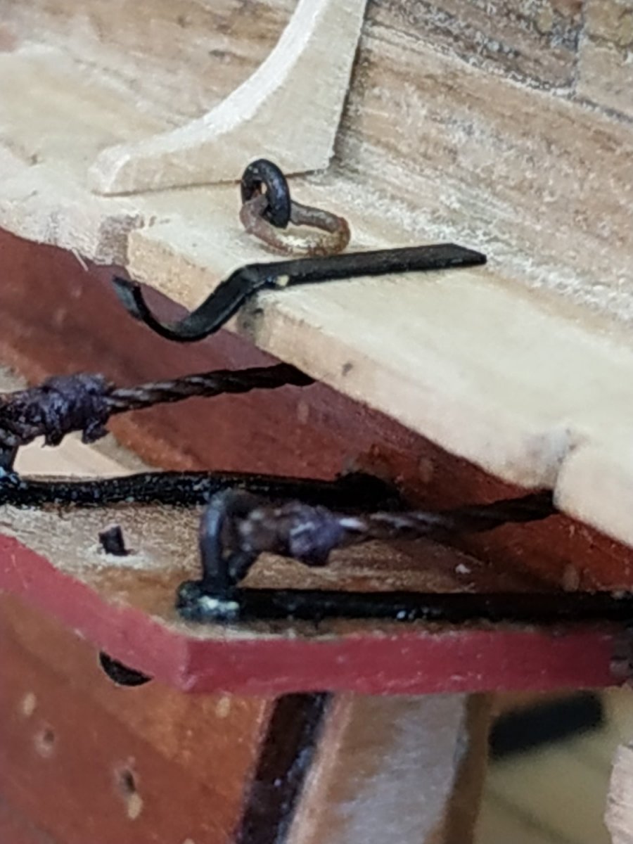
Main Studding Sail Boom Irons These are specialized iron supports fitted to the Main Channels for stowing a spar towed on its outer edge. Eyestrap- foreward and Gooseneck , aft. 1.6 mm wide, 0.53 tapering to 0.2 thick. The hole is just 0.75 mm diam. I found making these too difficult and adapted some old port lid hinges. A bit thin but seems OK at this scale.

-
Swan-Class Sloop by Stuglo - FINISHED - 1:48
stuglo replied to stuglo's topic in - Build logs for subjects built 1751 - 1800
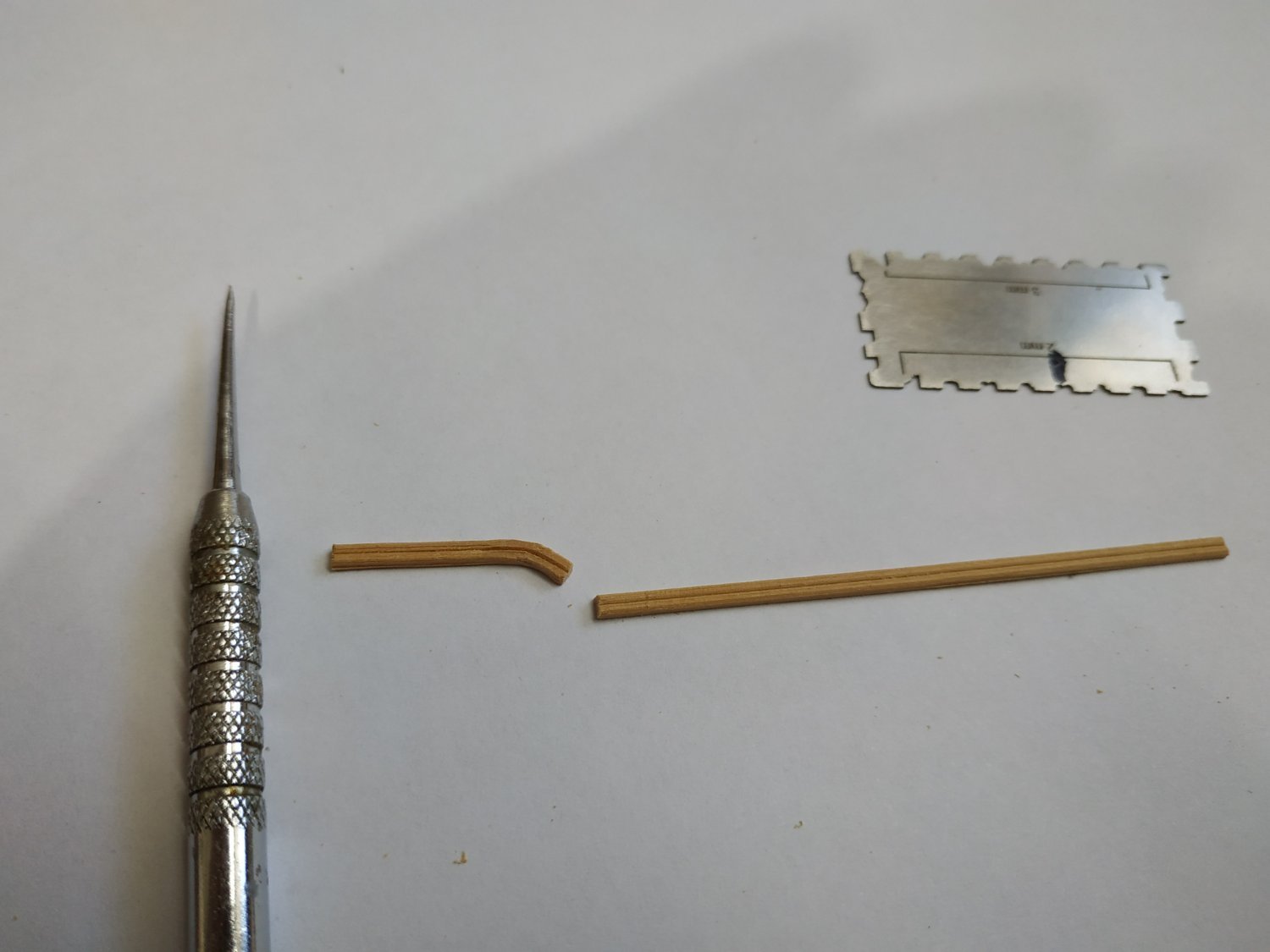
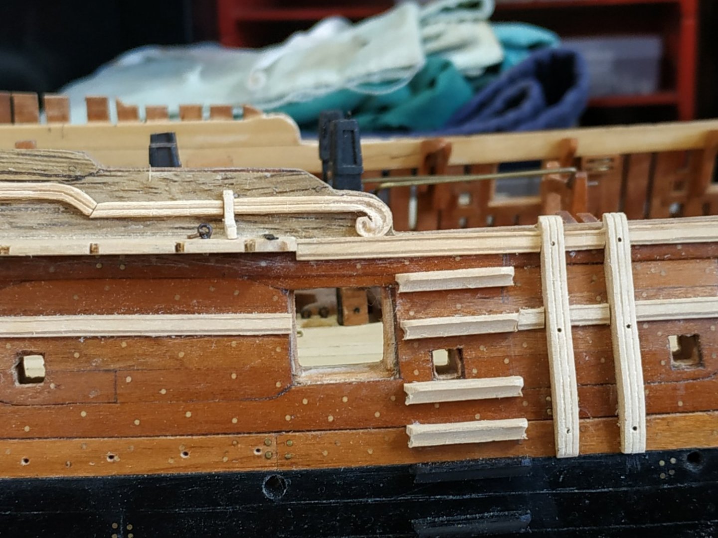
The Entry Steps. 6 in number, aft of the fenders. Size 17.5x3.71mm. The inner surface is shaped to allow the upper surface to be horizontal. The outer and side surfaces are molded. I took a long strip 3.71x3.18mm, uses the Artesenia scraper for outer shape, and use milling sphere and round file to match the ends to the molding. The lower 2 steps match the colour of the Wales. I lowered the 2nd step as the Atalanta plan shows it crossing the sweep port- surely not!!!!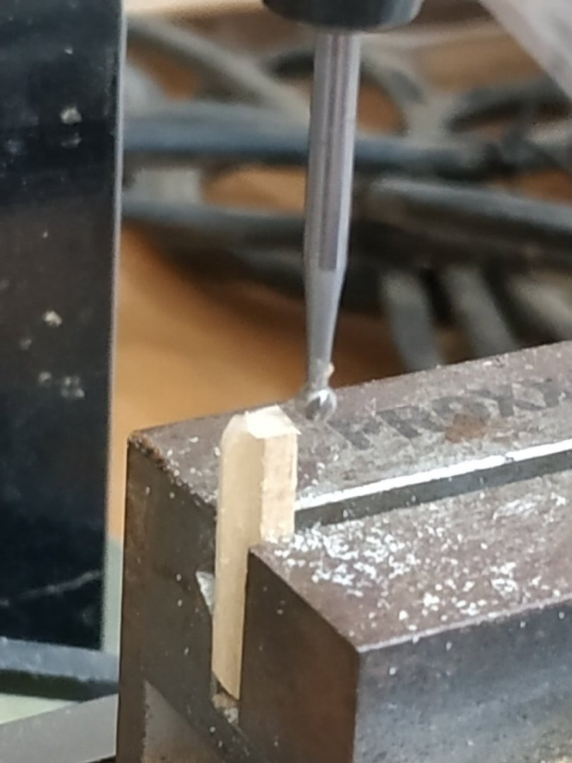
-
Swan-Class Sloop by Stuglo - FINISHED - 1:48
stuglo replied to stuglo's topic in - Build logs for subjects built 1751 - 1800
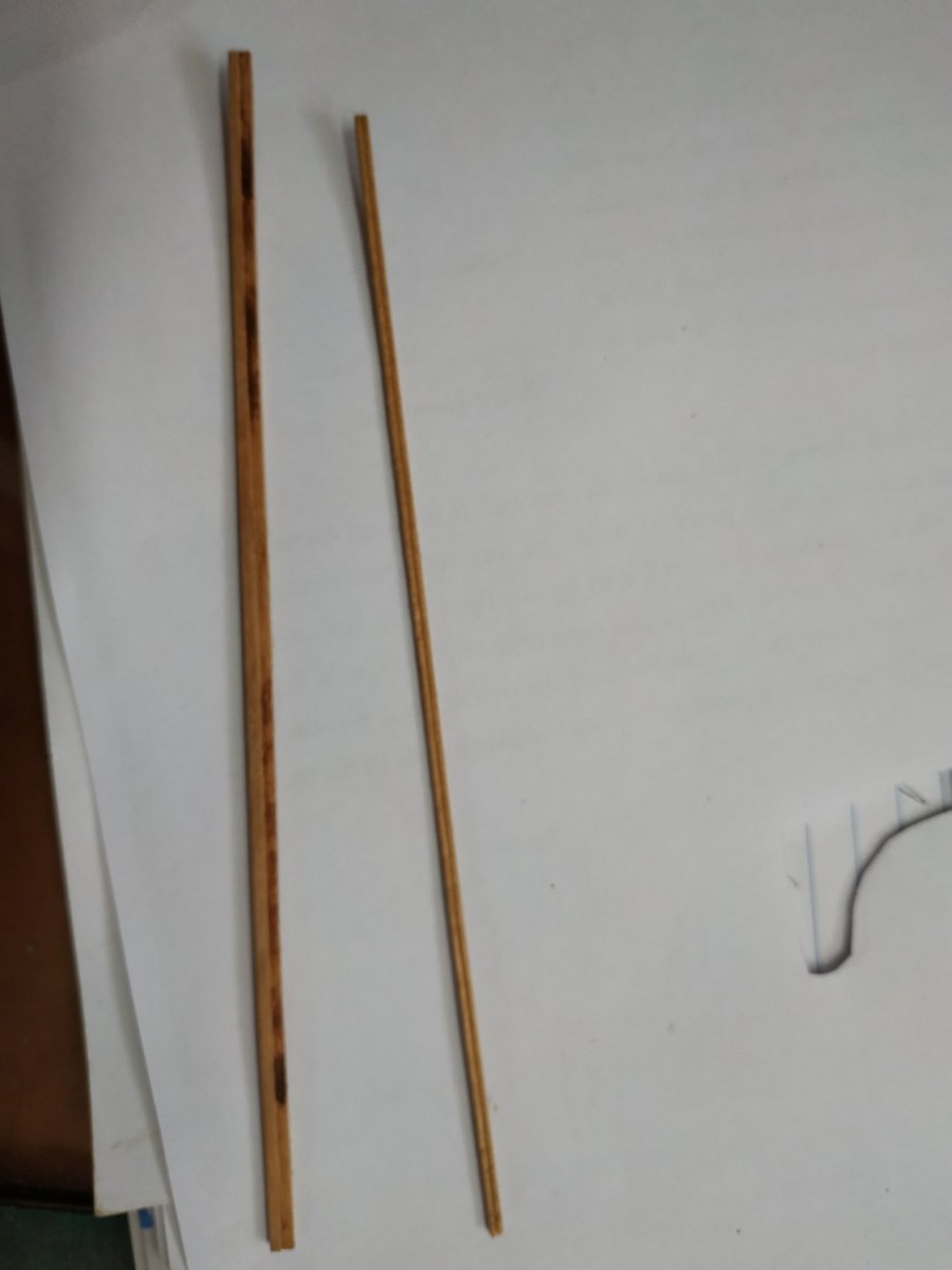
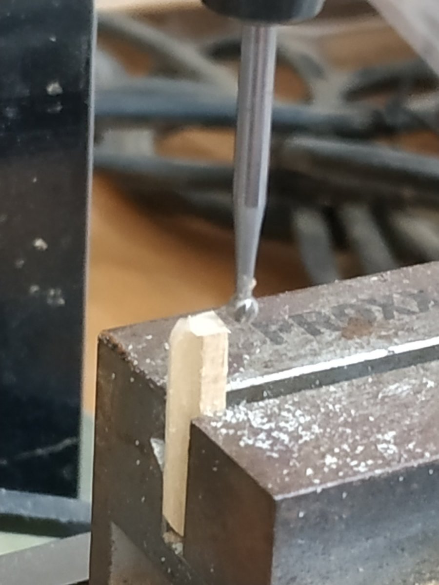
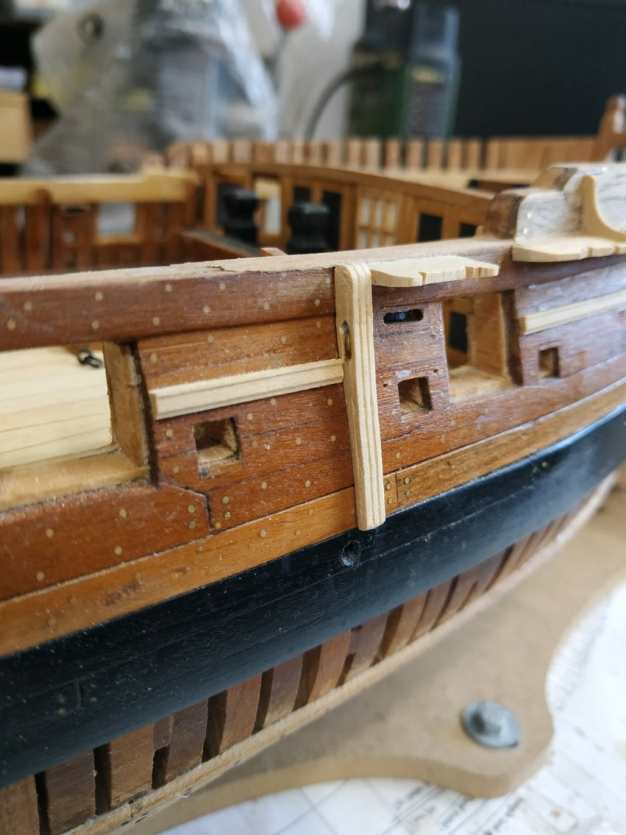
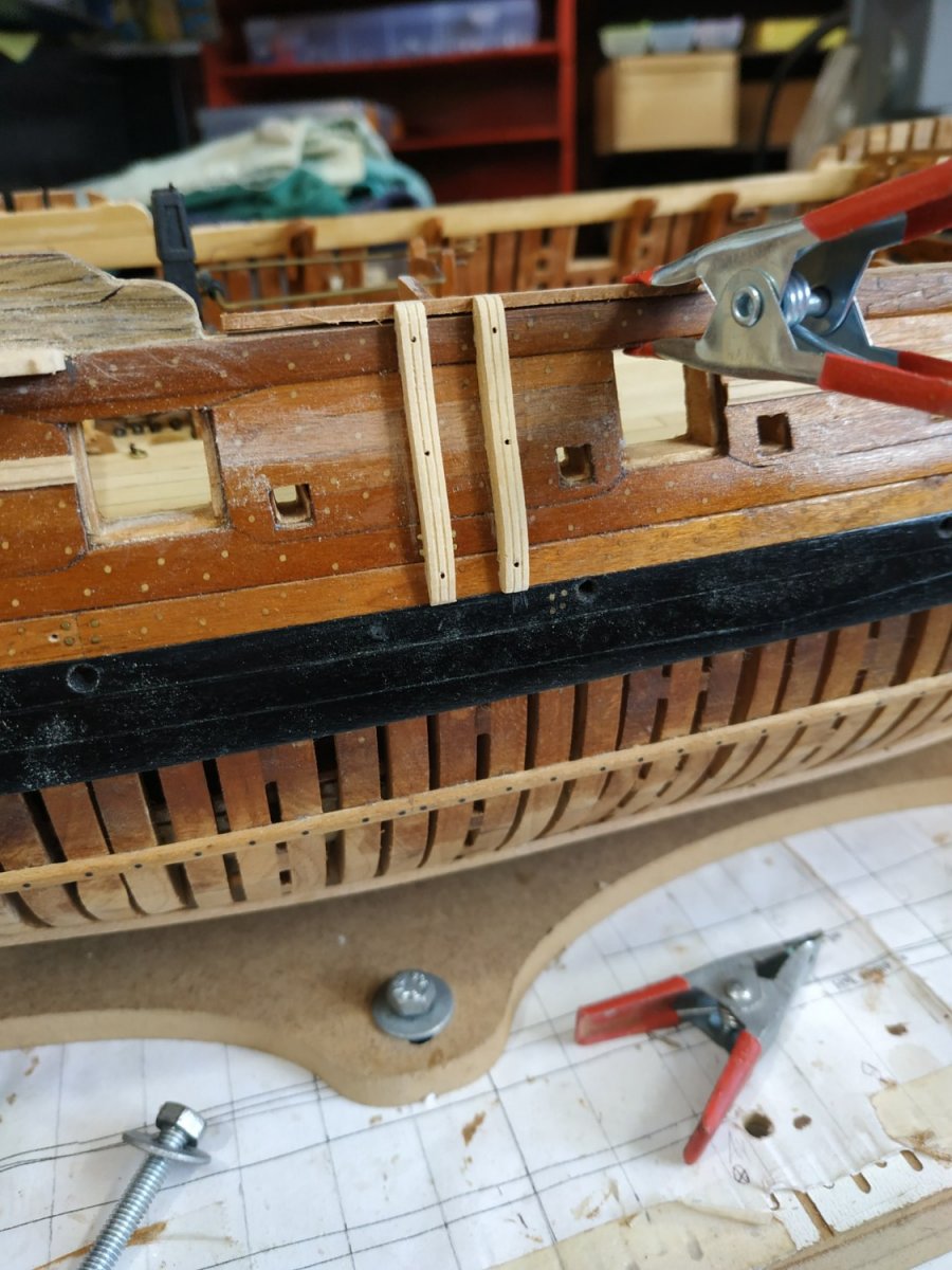
Chesstree. Vertical molding aft of the Forward Fixed Block. Upper part has a sheave for the main tackle leading to the fixed block. (TFFM says “ Sided “ but I;m not sure if this means depth or width or both, so used a square profile 3.18mm) The part is tapered to about half the depth, and slightly tapered to the lower end. Idon;t see how to easily taper the molding using the scrapper, so I ignored this latter slight taper. The upper end is level with the upper surface of (the yet to be fitted ) planksheer.This additional 1.6 is temporarily added. The lower end reaches the Wale. The Sheave is 2.65x1.0mm- centered on the center of the FFBlock. A closed loop of copper wire inserted to mimic the sheave. Molding shaped with my Artesena Scrapers Fenders. A pair of vertical moldings similar to the Chesstree (without a sheave), that protect the side of the ahull and facilitate the raising of barrels. It is therefore situated opposite the Main Hatch.
-
Swan-Class Sloop by Stuglo - FINISHED - 1:48
stuglo replied to stuglo's topic in - Build logs for subjects built 1751 - 1800
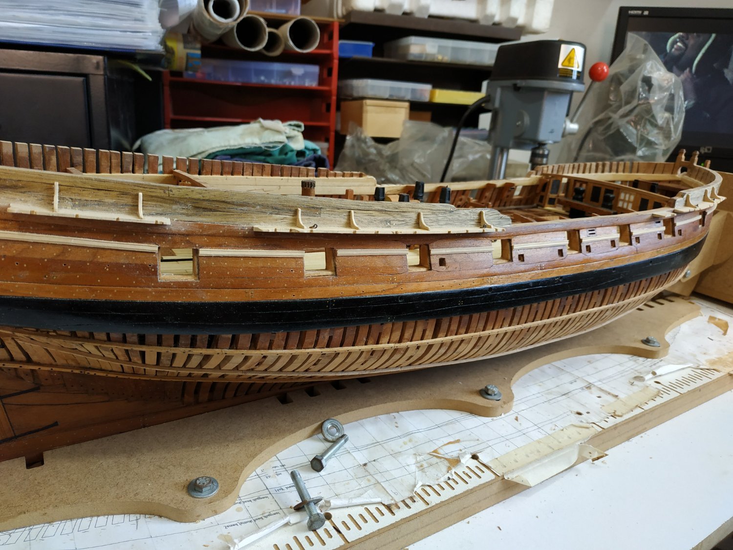
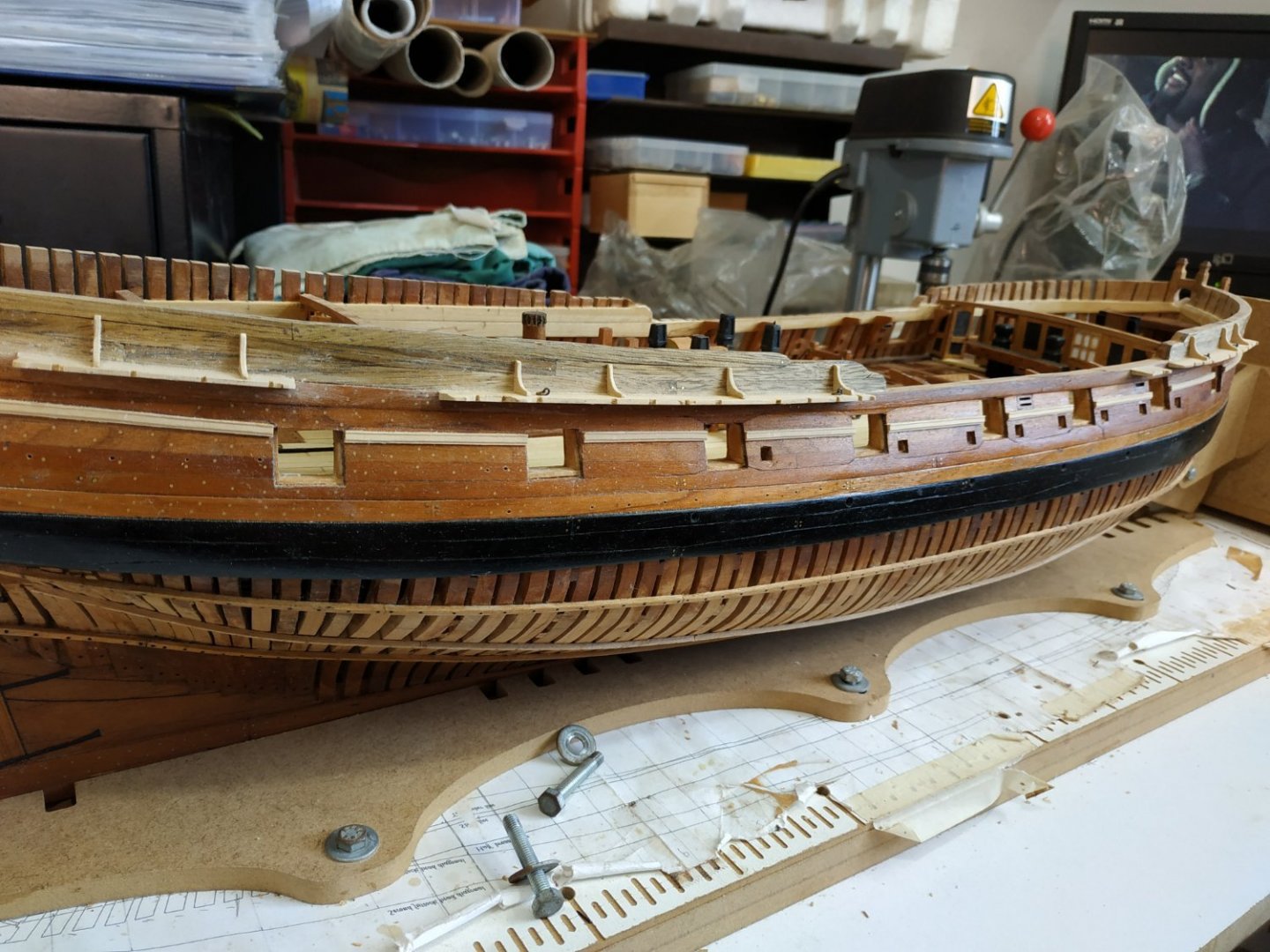
The Fore Channel Wedge-shaped in section-inboard 2.39 tapering to 1.46mm at outboard edge. Upper surface is horizontal. Width about 9.54mm. Inner surface curved to fit the hull. The AFT end is narrower to accommodate the anchor.( Picture shows this was mistakenly first attached at fore end. No prize if you spotted this,just the satisfaction of doing so.) The fore(leading) edge is S-shaped. Most of the outboard edge is recessed and there are notches cut for the Holding Chains. The position of these I took from my sheer Atalanta plan, as they are not exactly as shown in the scale illustration. The “recess” will later be filled by a molding. 3 short, reinforcing pins are set into the inboard surface, and matching holes drilled into the hull. The Channel is attached by PVA on the wood, and CA glue on the pins.The long bolts mentioned were not used and would not be seen. 2 ring bolts are fitted where shown. The Stool. A short narrower Channel fitted aft of the Fore Channel, but of similar design. Main Channel. Same dimensions of the Fore Channel. An alternative aft section is suggested which is narrower (smaller dead-eyed ) rather like an attached Stool. It follows the horizontal curve of the hull, but the wood is flexible and the reinforcing pins are enough to do the job. Also has 2 ring bolts Mizzen Channel Smaller (2.12x1.33mm) and narrower. Standards Wooden supports above the larger Channels. Shaped like a hanging knee. 1 mm thick and concave hypotenuse side is chamfered. Ensure their position doesn't interfere with line of holding chains.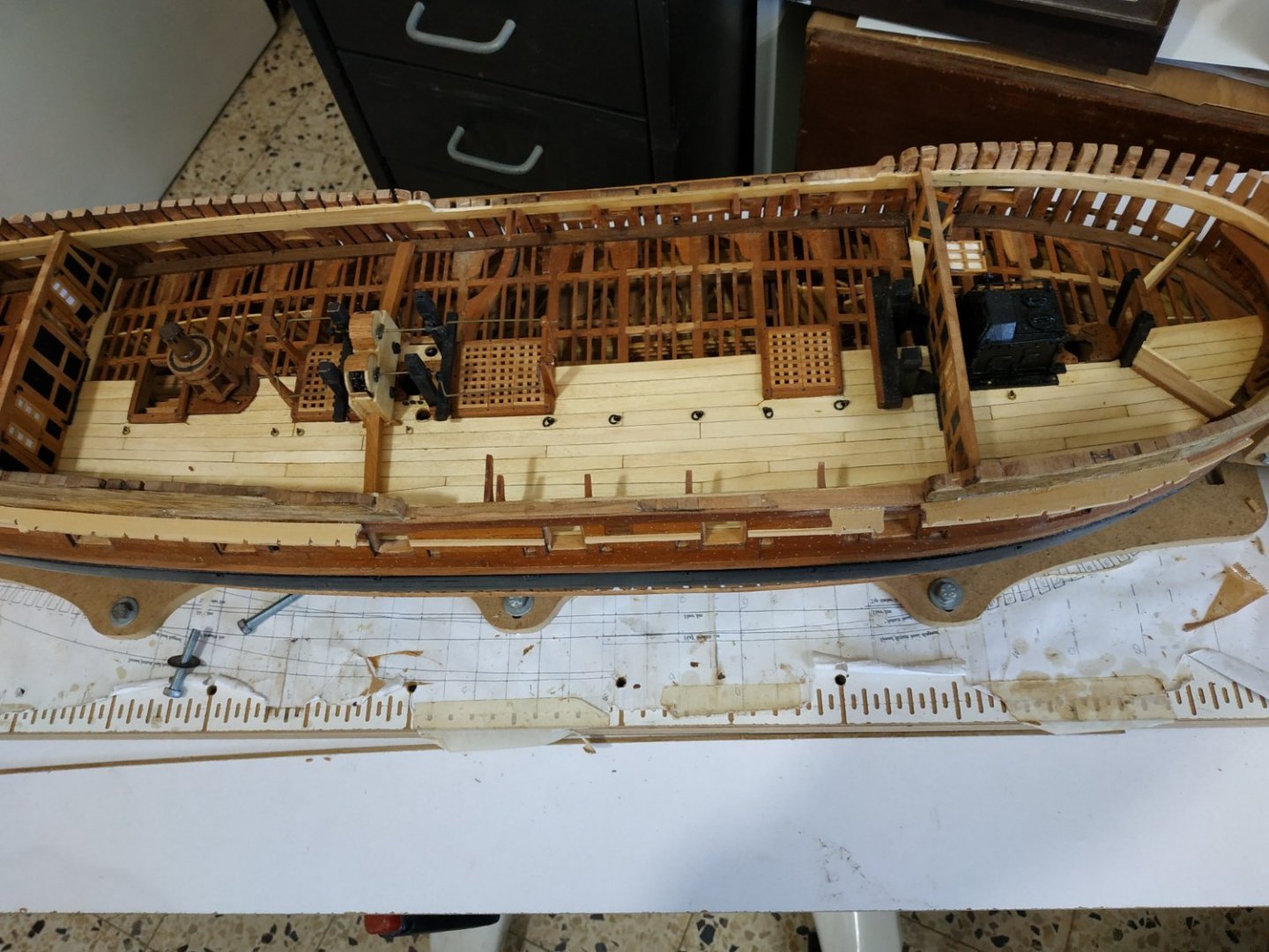

- 475 replies
-
- 14
-
-
Swan-Class Sloop by Stuglo - FINISHED - 1:48
stuglo replied to stuglo's topic in - Build logs for subjects built 1751 - 1800
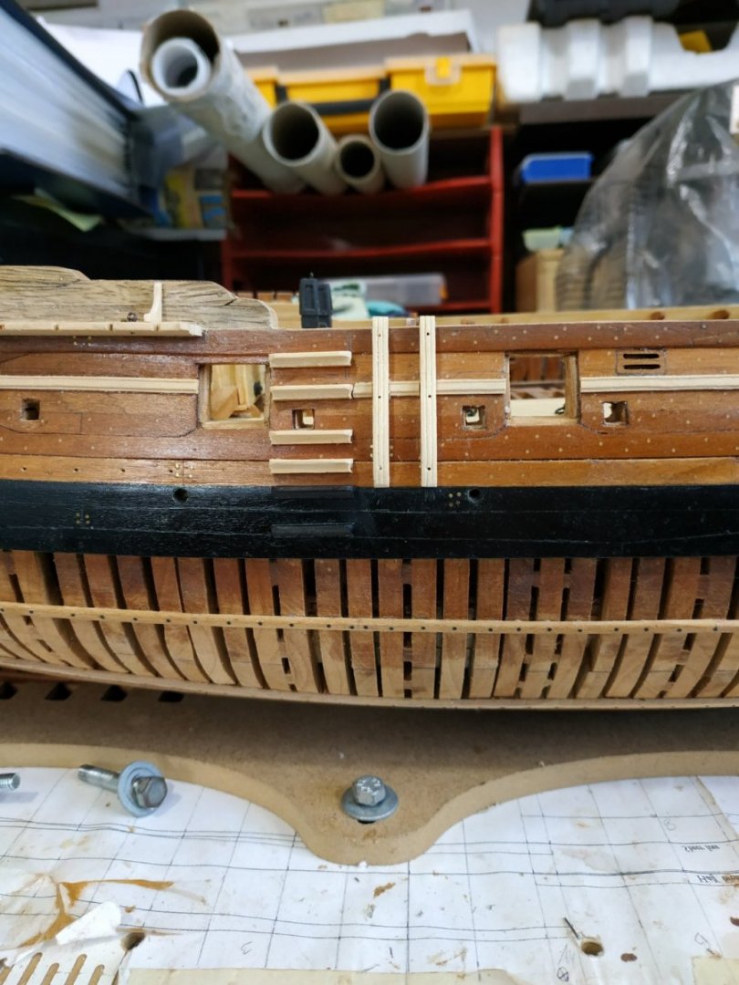
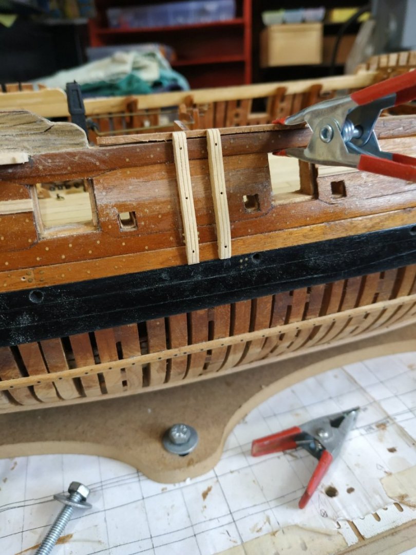
Moldings. As Monty Python would say “and now for something completely different” Ornamental strips whose outer surfaces are shaped. Truck Molding It covers the seam of the lowest plank of the Lower Counter. The inner surface needs some shaping to follow the curve- its outer end is rounded where it meets the side of the hull. Taking a profile of 2.12mm sq.,my first proper opportunity to use the Artesina Latina Scrapers. I used boxwood and it really is fantastic for this purpose. Waist Rail Position on the Sheer Plan Profile 3x1.2mm. The line or run can be helped by using a temporary thin batten whose upper surface can place and support the Rail. This rail has some interruptions for the Chesstree and Fenders, but I chose to fit the rail continuously, and remove these areas later. Sheer Rail Parallel to the waist rail, but larger interruptions for the Channel - I will make them after the Channels are fitted.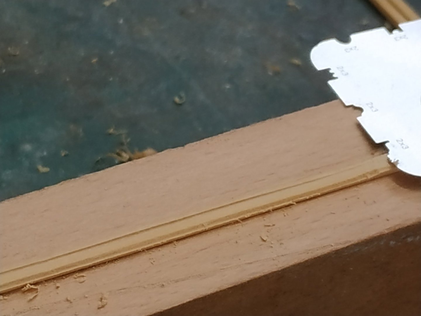

-
Swan-Class Sloop by Stuglo - FINISHED - 1:48
stuglo replied to stuglo's topic in - Build logs for subjects built 1751 - 1800
Armaments- to be omitted I think these are optional for this kind of “open” or admiralty model. I’ve no experience in turning brass for guns, and not much interest at present in purchasing cannons. It would probably add several months to the build and I want to press on. Gun Port Lids According to TFFM and models used for illustration,lids were only fitted in some of the ports- 1st,for the manger, 8th and 9th, for the captain-the naval priority is noted. THe 1st is a narrow port so the lid is hung vertically with the hinges on the fore edge. This and the other Lids are constructed in 2 layers - the outer with (and matching) the run of the hull planks. The inner at right angles. The total thickness of the lid is the same as the outer hull planking so that, when closed, it is flush with the hull, including any curve. Our model therefore requires plank 0.53 thick,the width to match the hull planking at each port hole. Added a bevel on the lower edge to enable closing. The Inner surface is traditionally painted red. I thought to delay fitting until after other hull structures so as to avoid damaging them. Thats why the pictures are out of sequence. MISTAKE. Access is restricted. Anyway, the hinges came with the other etchings. A pair of holes above the port hole for hinge insertion, and another pair for the lanyards. The lanyards are missing from the 1st port Lid (3D rendering) and are ?hidden by the bow structures in the illustration model. I’ve omitted them.

-
Swan-Class Sloop by Stuglo - FINISHED - 1:48
stuglo replied to stuglo's topic in - Build logs for subjects built 1751 - 1800
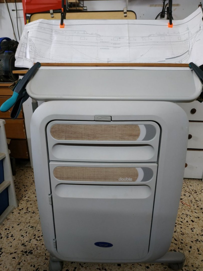
Another Something for the Workshop Found discarded in our local hospital dumpster. (I promise, not “liberated”) Tilting and rotating tabletop. Drawer and cupboard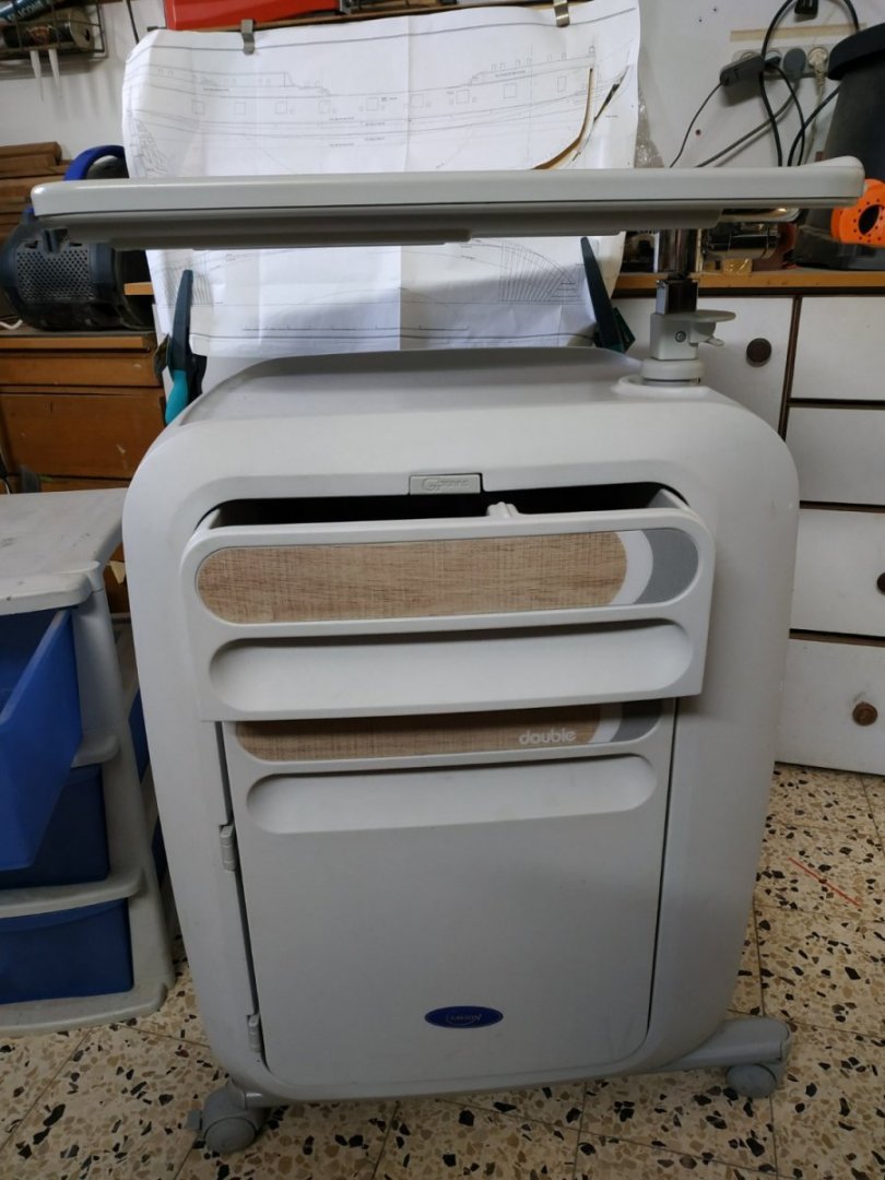
-
Swan-Class Sloop by Stuglo - FINISHED - 1:48
stuglo replied to stuglo's topic in - Build logs for subjects built 1751 - 1800
Stopper Bolts and Top Tackle Eyebolts and Eyebolts around the main mast. Already fitted -before the cistern hoods- after which is difficult Gun Tackle and Beeching ringbolts- These are omitted as I do not intend to fit cannons on this build Preparing for the Chain and Preventer Bolts. In order to accurately find their position and angle, temporary (dummy) masts are made to set their angle and mark the height of the hounds. TFFM gives these heights, and the angles are taken from the profile plans. Also there are extensions to be made to allow for the Backstays. ****At this point I remembered that I do not intend to mast the ship. Using the Atalanta Sheer Plan, I think the position and angles are adequately shown. Therefore the mast fitting ( the word “dummy” is now significant), was unnecessary. Note: mizzen mast has no Preventer Plates
-
Swan-Class Sloop by Stuglo - FINISHED - 1:48
stuglo replied to stuglo's topic in - Build logs for subjects built 1751 - 1800
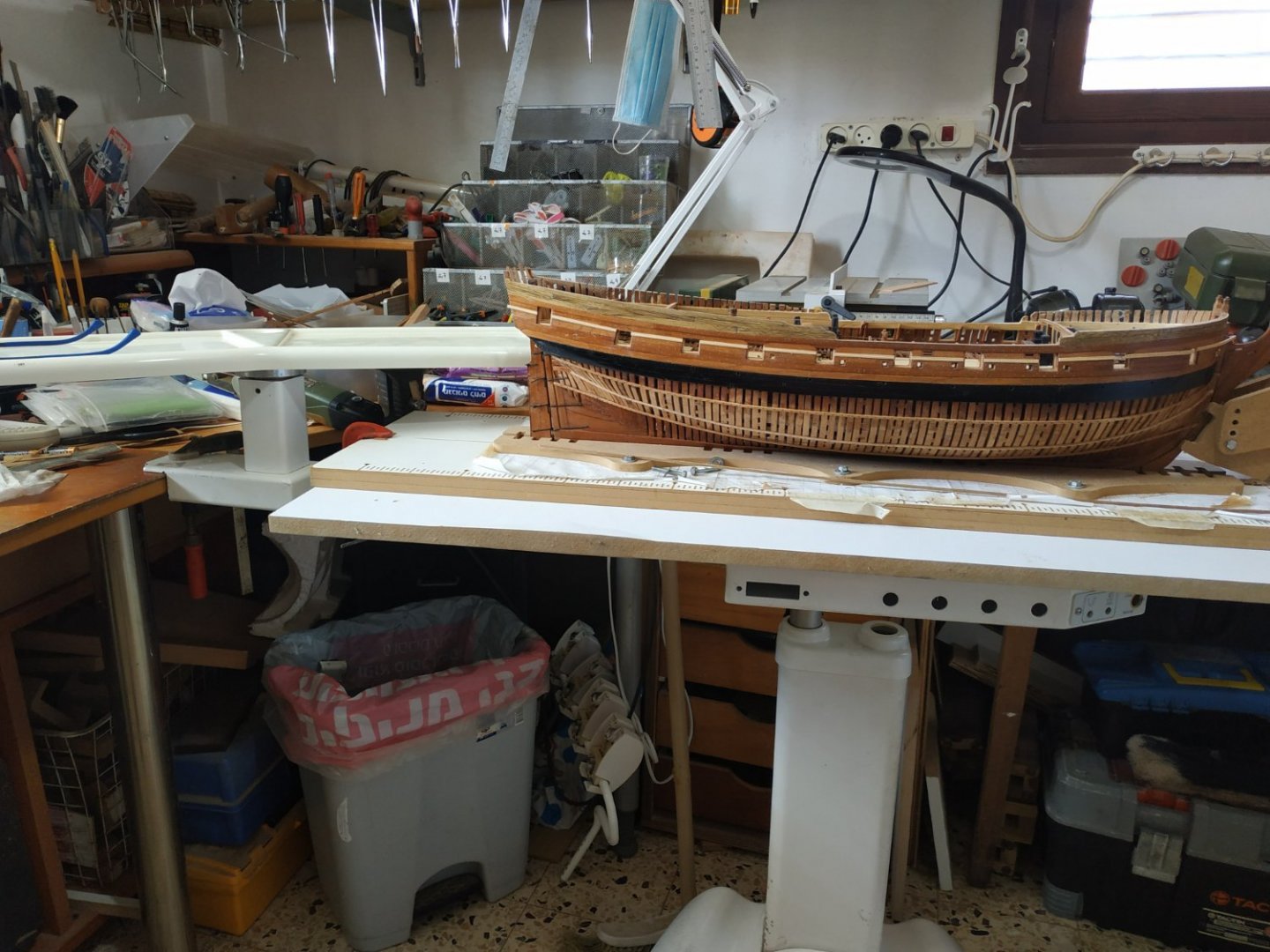
Upgrade for Workplace. My dentist retired. As an old friend he gave me his work table. Dispensed with the air pressure and electrical system (which I now regret) and managed to break the porcelain top (I’m a clumsy bugger ). As the higher instrument table interfered with access from both sides, I removed it and attached it to my work table with a clamp. The main table can be unlocked, rotated and raised by at least 50cms. The top is replaced by an MDF board to which my Building Slip is attached by clamps.
-
Swan-Class Sloop by Stuglo - FINISHED - 1:48
stuglo replied to stuglo's topic in - Build logs for subjects built 1751 - 1800
Knees to Gangboards. Support the walkways between the Forecastle and Quarter deck. A set of 6 either side. These Hanging Knees are 2.12mm thick. The first 5 have an arm 9mm and leg 17.5 mm- the sixth has a short leg but arm of 17.5mm The arms are set to allow for the thickness of the gangboard, so the upper surface is level with the top of the Bulwark. Reading ahead, the forecastle planks are 1.33mm - I allowed this for the gangboards. Also the arms are angled as are the quarter deck beams. Estimating this is not so easy, and I expect some adjustment when the Gangboards are fitted later in the build. **When fitting the aftmost (6th) Knee, I realised that the Forecastle Bulkhead and Beam was about 4 mm too aft. This was therefore unglued (alcohol) and re-sited in the correct position**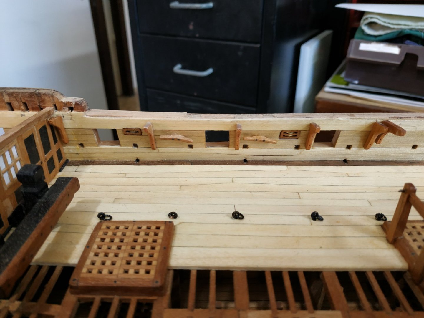
- 475 replies
-
- 10
-
-
Swan-Class Sloop by Stuglo - FINISHED - 1:48
stuglo replied to stuglo's topic in - Build logs for subjects built 1751 - 1800
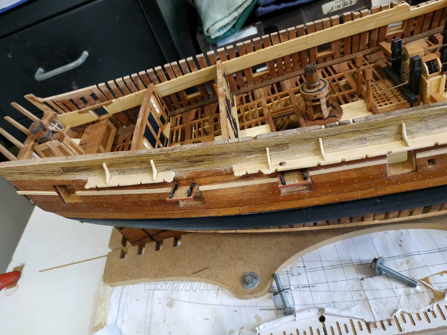
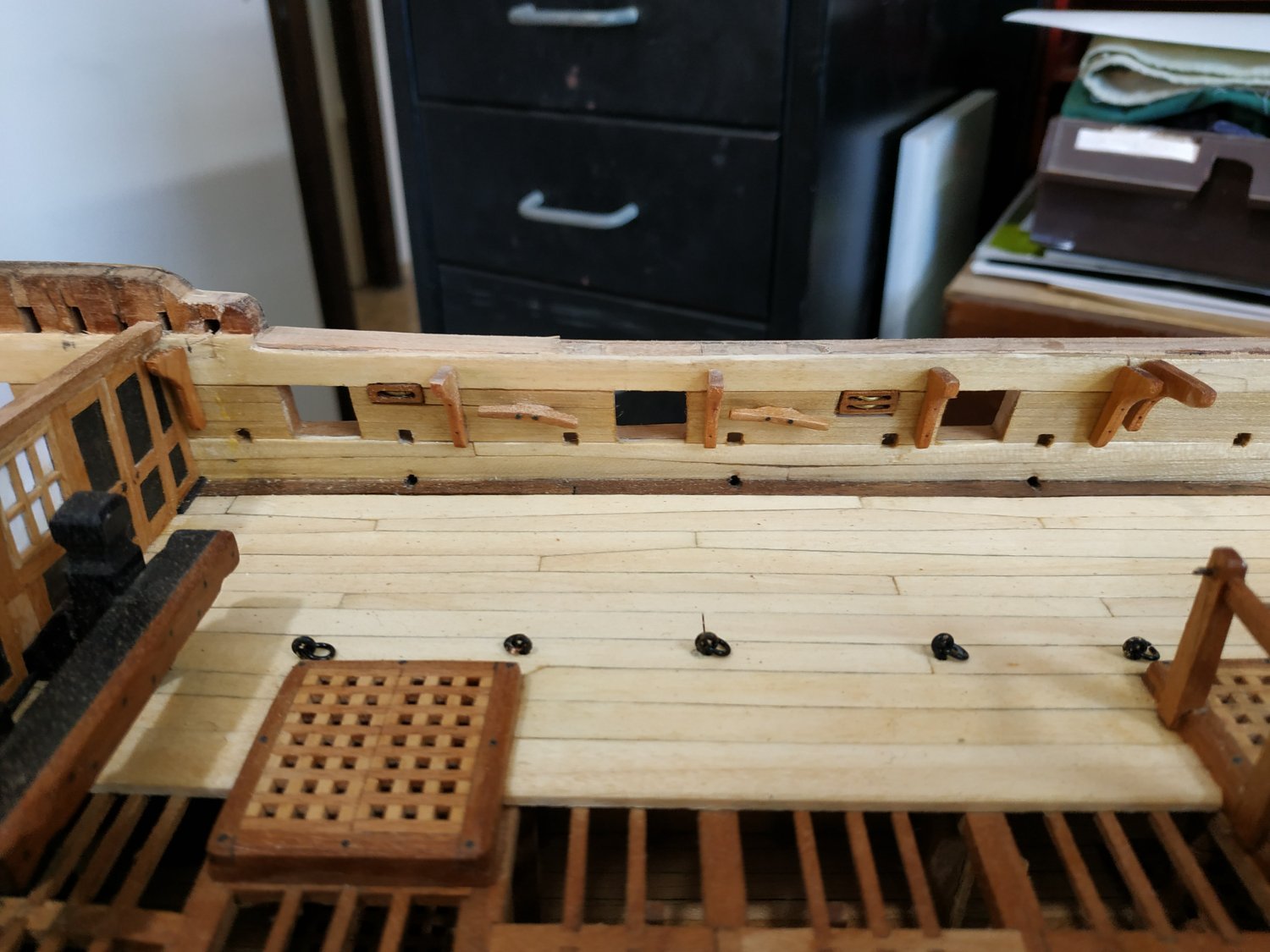
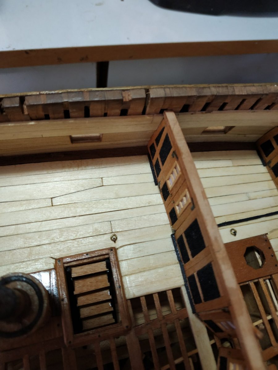
Companion Ladder. Aft hatch left open to allow fitting and viewing of ladder Formed as previously. But angle must allow the feet to clear the opening below. A reminder that the treads are parallel to the deck NOT horizontal. Range Cleats. Between and at the level of the Fixed Blocks, fore and aft, and angled fore-up. They are shaped as modern cleats, 17.5mmlong and 1.6mm wide. Fixed to the Quickwork at the waist of the Hull.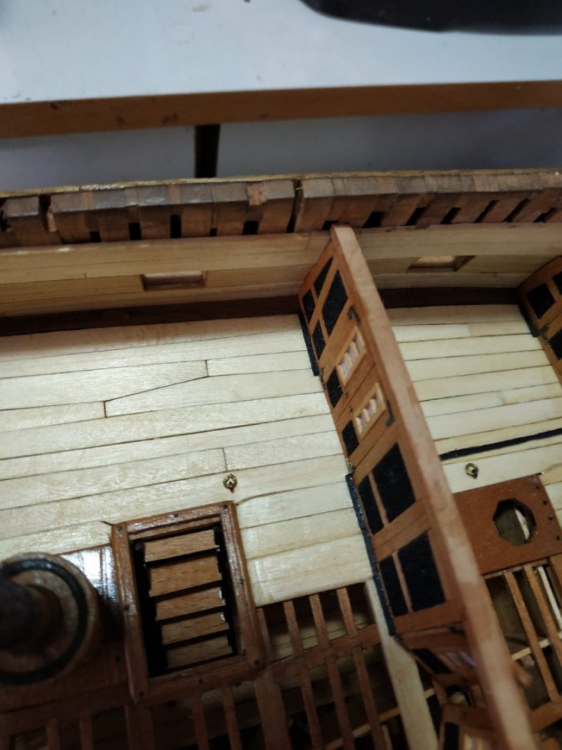
-
Swan-Class Sloop by Stuglo - FINISHED - 1:48
stuglo replied to stuglo's topic in - Build logs for subjects built 1751 - 1800
Short Break from Model Building. Difficult, but worthwhile. 2 weeks touring Egypt. Cairo/Luxor/Nile cruise/Aswan and Abu Simbel Magical places, not only for history buffs. Wonderful people. (View at breakfast on the first day, Felucca on the Nile, Abu Simbel and yours truly.)


-
Swan-Class Sloop by Stuglo - FINISHED - 1:48
stuglo replied to stuglo's topic in - Build logs for subjects built 1751 - 1800
purchased ready made along with a sheet of photo etched parts, specifically for the Swan Class. My attempts are embarrassing botches. -
Swan-Class Sloop by Stuglo - FINISHED - 1:48
stuglo replied to stuglo's topic in - Build logs for subjects built 1751 - 1800
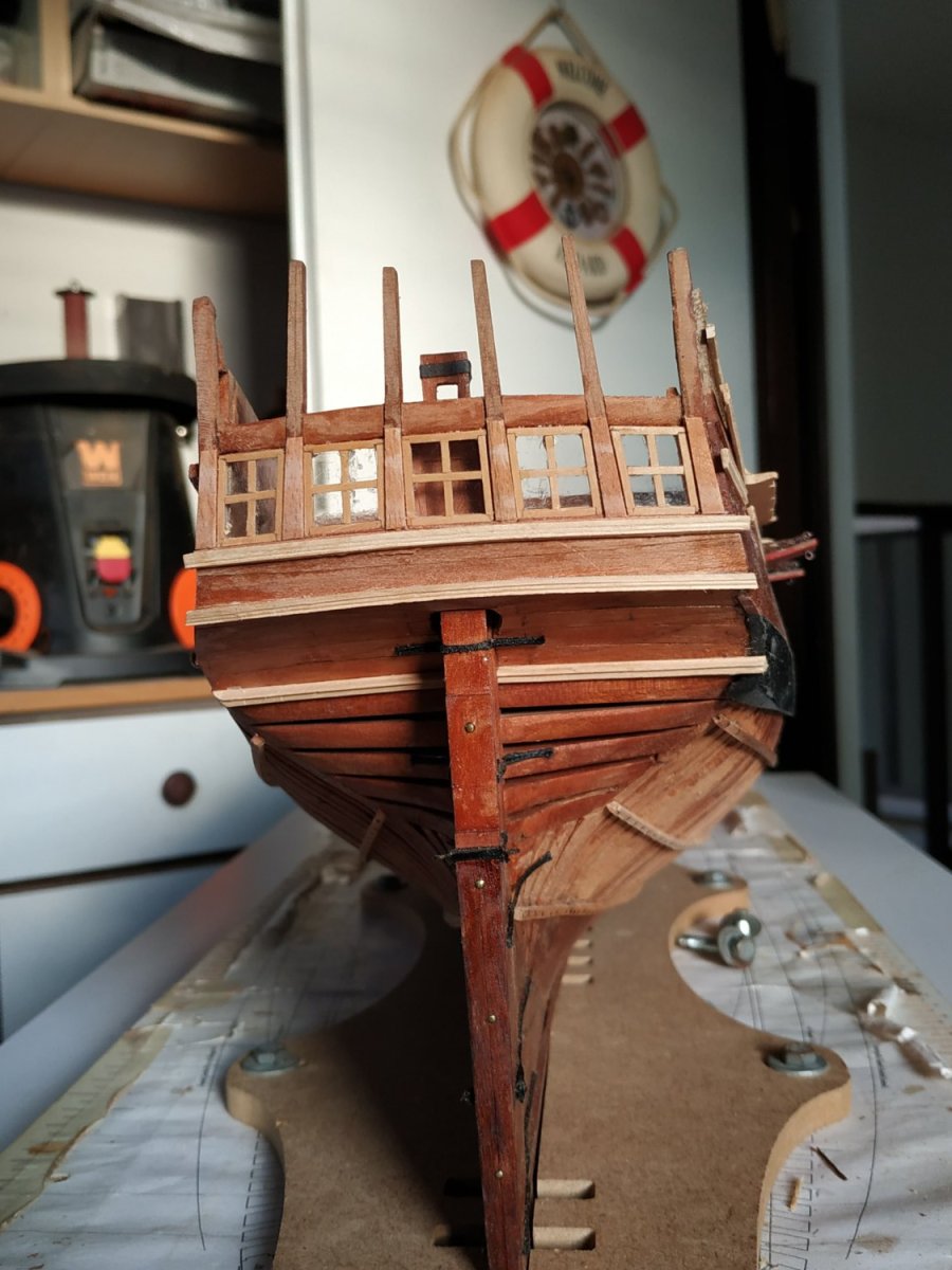
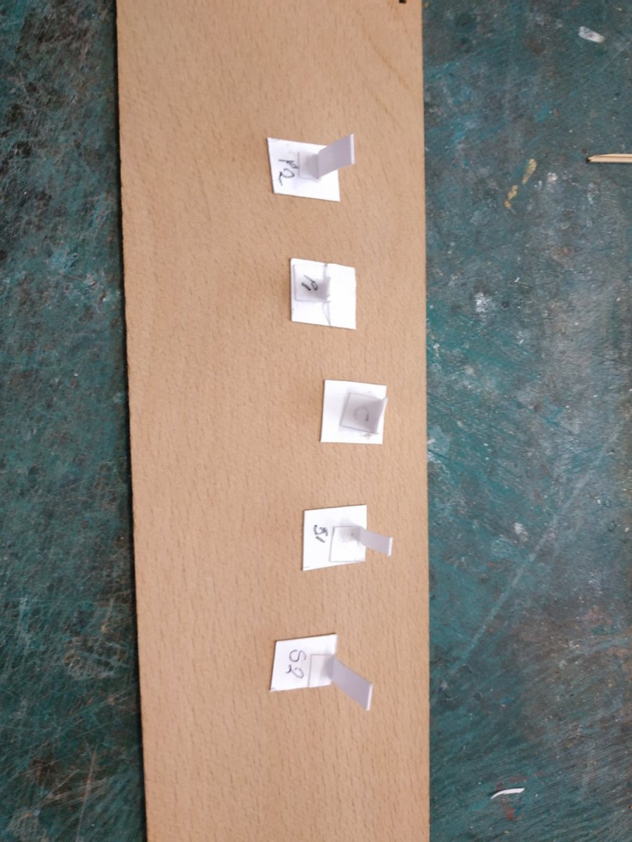
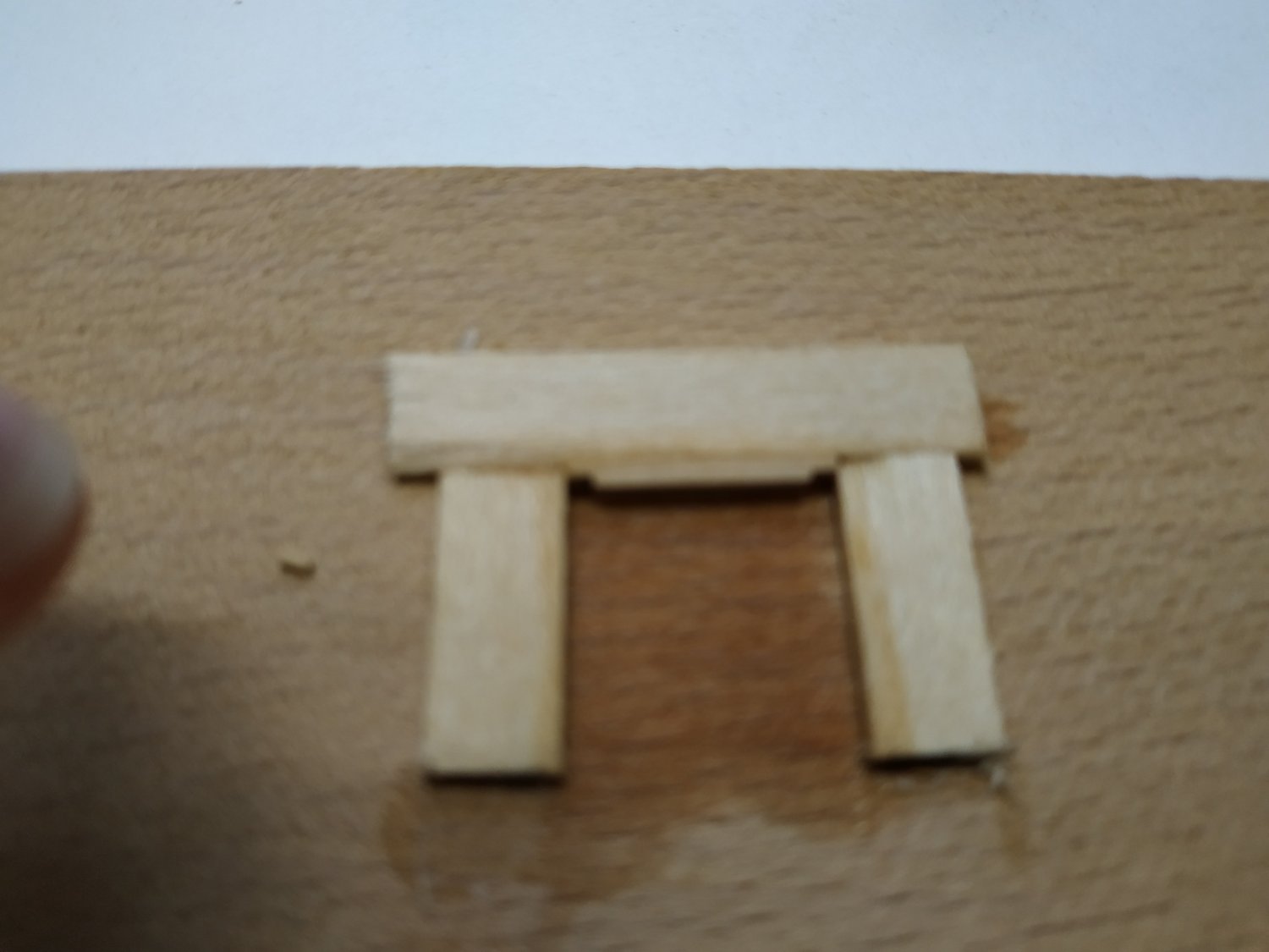
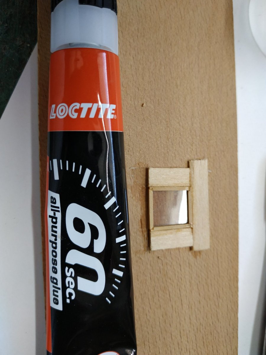
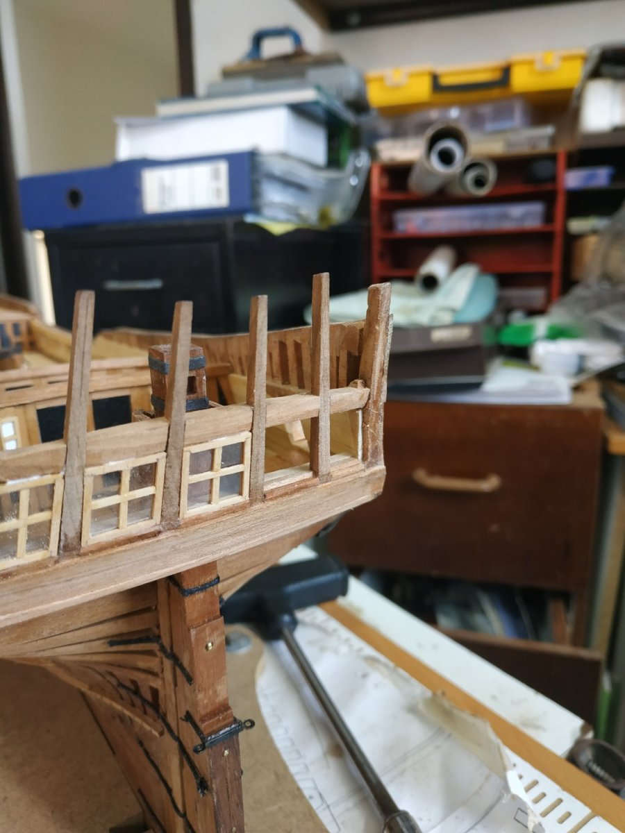
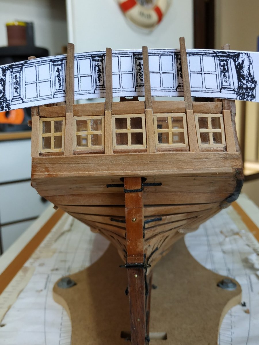
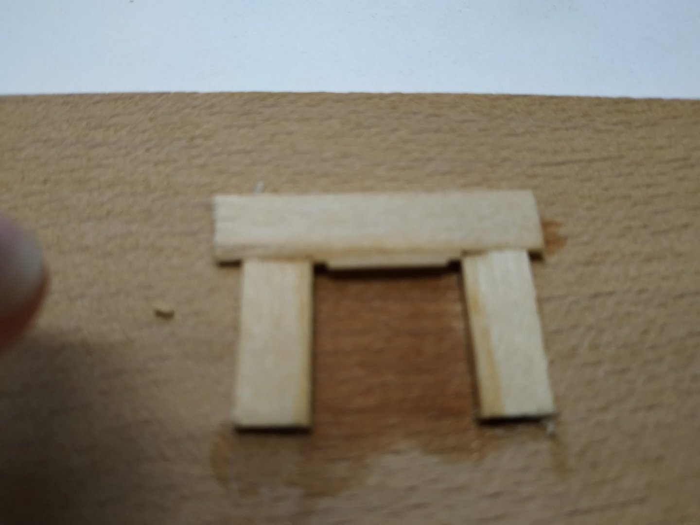
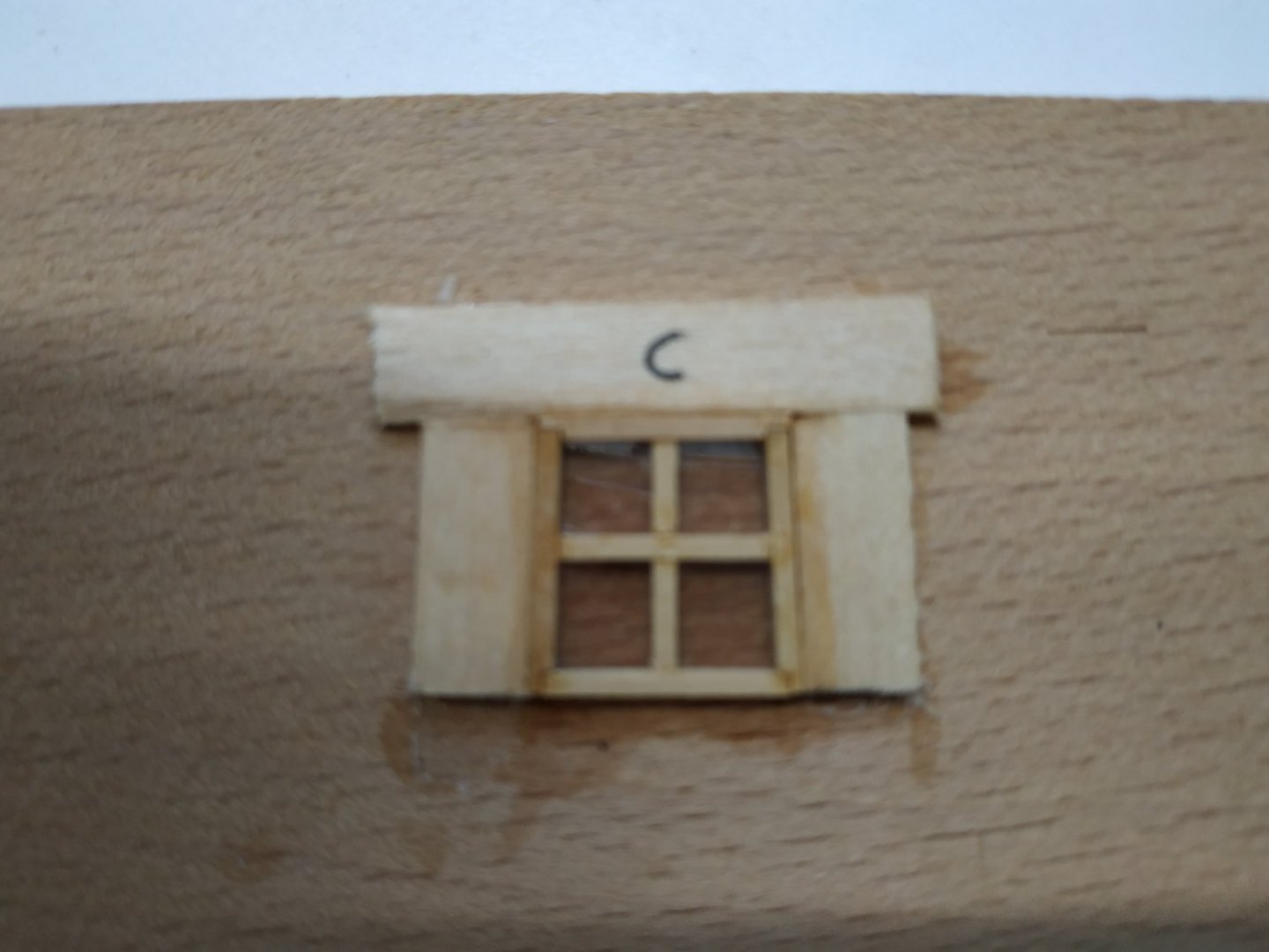
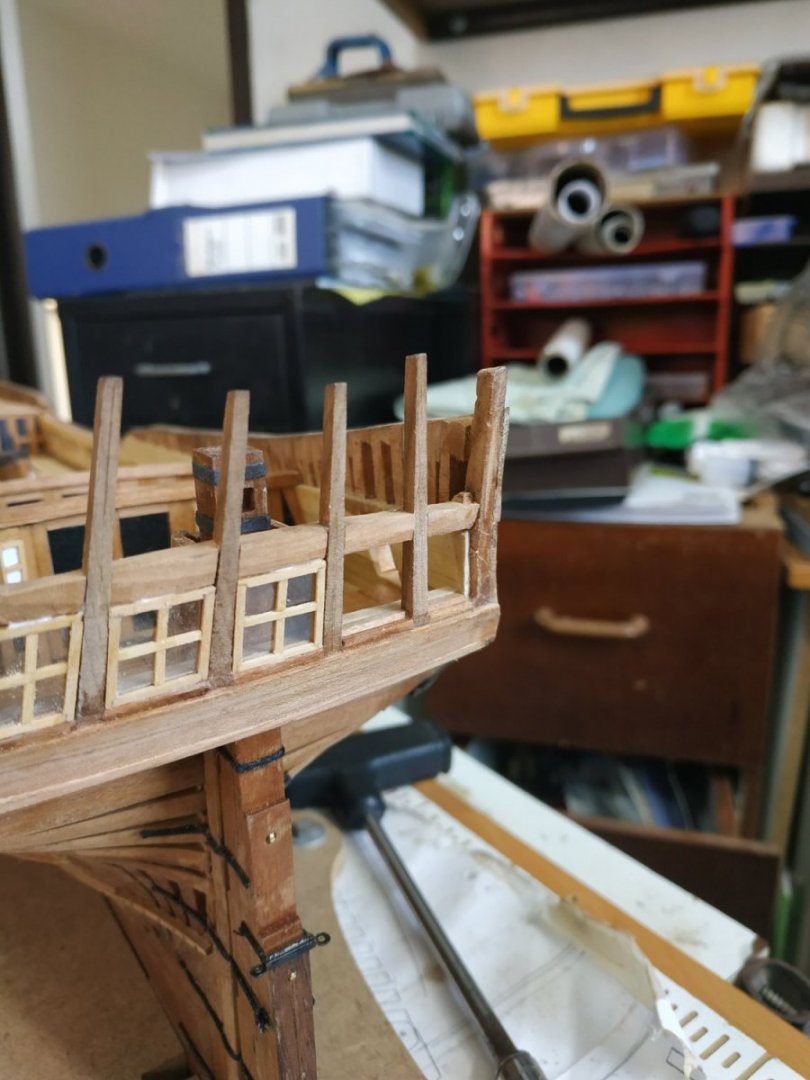
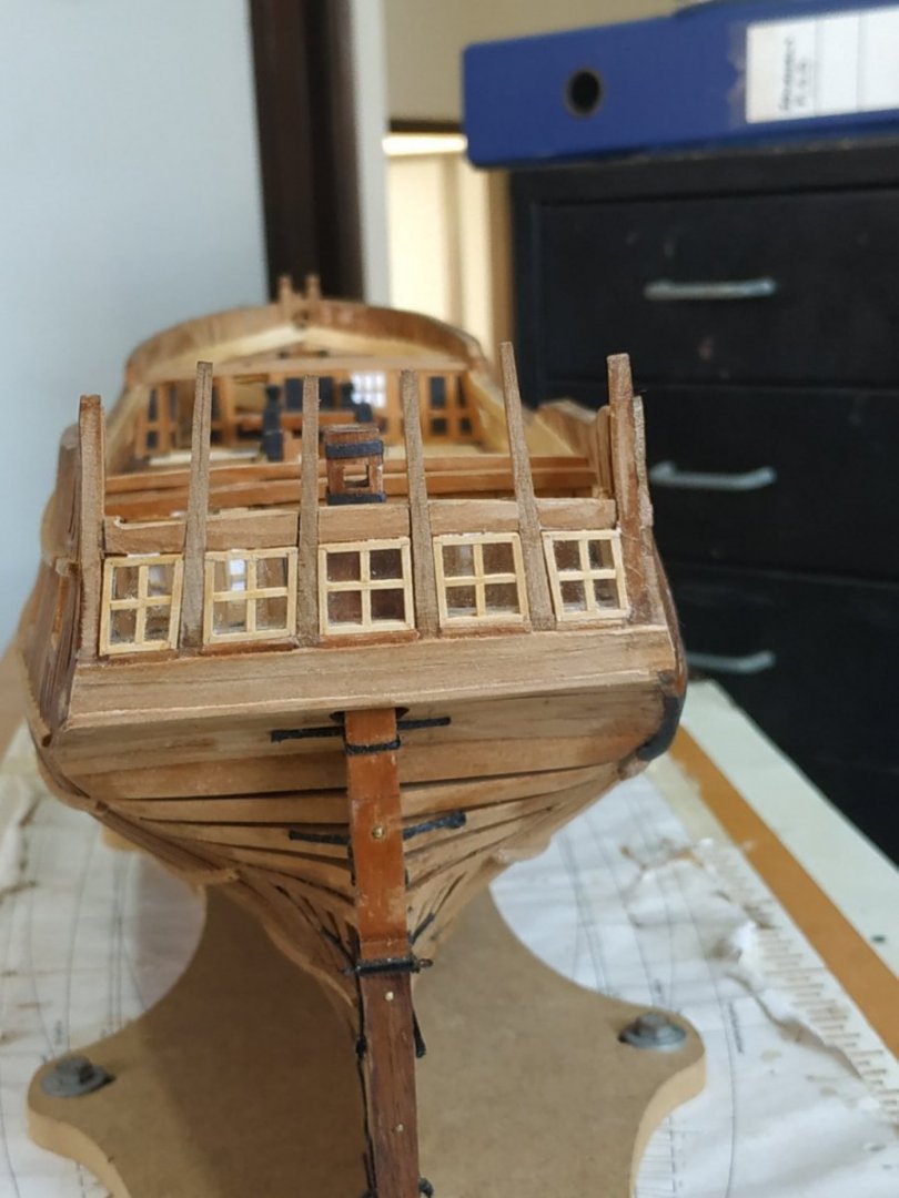
Stern Lights cont. As the rebate of the side stops and inner sill depend on the frame thickness, I will fit them after the frame is made. The frames are not squares. Patterns in card are made individually. A card tab is attached to ease the constant handling to cut and fit. The final pattern is placed on a flat piece of wood and snuggly surrounded on 3 sides by strips, which are glued to the wood. . Check pattern is still a snug fit.The pattern is removed and glue allowed to dry. The jig is oiled to prevent the frame sticking. My grooved wood is fitted into the jig on the same three sides. The joint is made by removing the “walls” of the groove for 1mm, of one side, so its partner fits. I used a different glue, because the area of the joint is too small to rely on the usual PVA, and epoxy too viscous and messy. Glass hates me, so I use some acetate sheet that I have left from a kit, and using the previous patterns, cut to size and insert in grooves. The 4th side of the frame can now be fitted. The cross pieces that divide the pain are made from the boxwood at 1x0.65mm, and the same Loctite glue is used. Despite care and the tiniest amount, some will spread to the pain. I was happy to see that this doesn’t stick and can be scraped away. The lights can be trial fitted. They are surprisingly rigid. The depth of sill rebate can be confirmed, and the (inner) sill made accordingly. The lights fitted, the side stops (0.5mm thick) are then fitted from within the hull, and after glue dried, trimmed to Counter Timbers. A covering board is fitted - a counterpart to the Munions that are on their aft aspect and tidy-up the stern framing. This Loctite glue is one to remember for such small, delicate situations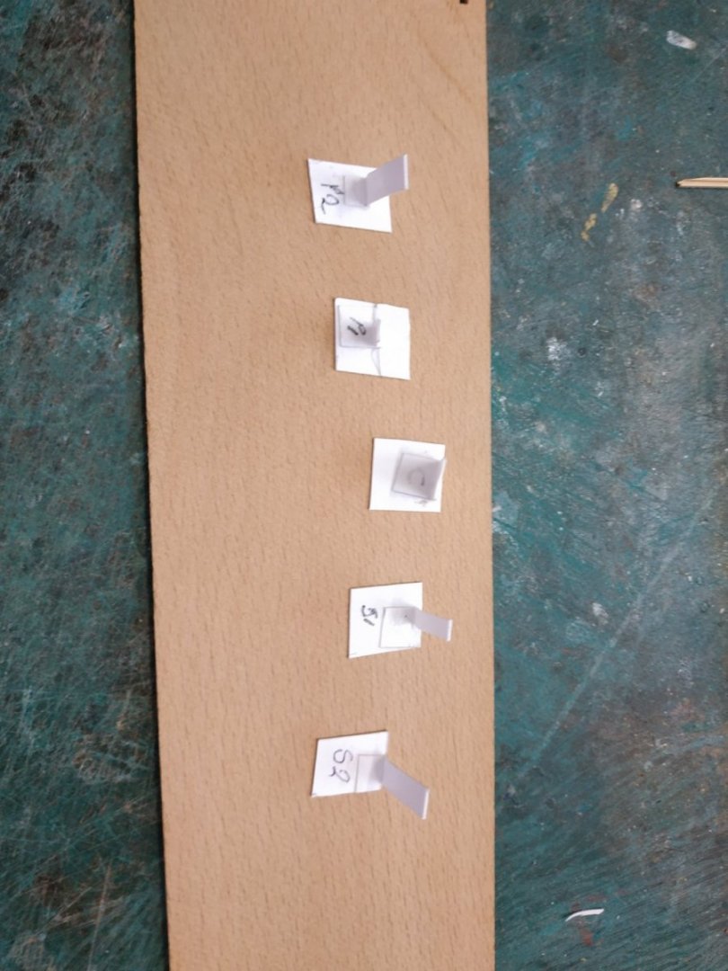


- 475 replies
-
- 11
-
-
Swan-Class Sloop by Stuglo - FINISHED - 1:48
stuglo replied to stuglo's topic in - Build logs for subjects built 1751 - 1800
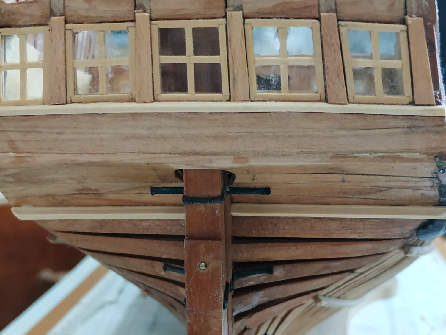
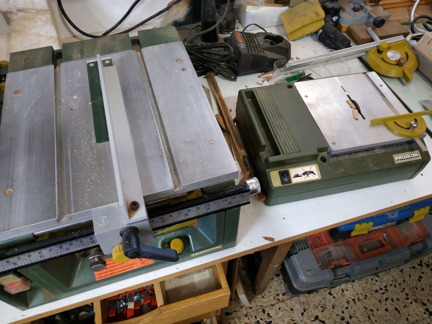
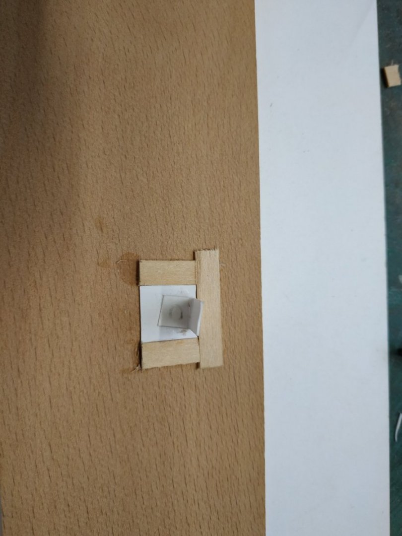
Stern Lights. Some time ago I mistook the meaning of lights, but was glad to see C.Napeaon Longridge refers to them as “windows”. I checked out his book as I found TFFM confusing. After starting with TFFM, I moved to adapt Dan Vardas’s method and only after I finished, all became clear when re-reading TFFM. As I (think) I understand, the forepart of the surrounding of the frame, also forms the fore aspect of the frame itself. I.e. the inner sill and side stops hold the glass (or substitute) itself. The aft part of the window frame is made separately, and the window pane “sandwiched '' between this and the aforementioned fore aspect (sill and stops). The position of these stops, which form a rebate, depends on the frame thickness as these sit flush with the Stern Counter Timbers. Here I became confused, not realising that the TFFM method avoided inserting the window pain within the window frame. Anyway, I made the window frame as shown by Dan Vardas. This is an example where the tools and type of wood really do make all the difference. I used some Boxwood that I saved for the last 10years. The frames called for 1x1.8mm strips. I thinned a sheet to 1mm (cried over wasted dust from the Thinesser) Took a 0.5mm blade from the “baby” table saw (50mm diam) and fitted to the bigger Proxon table saw.(smallest 80x1mm). Able to set depth to 0.5mm and 0.65 in from fence , cut on full bank, an only after, at 1.8mm from fence, separate the grooved strip. The resulting cut in the boxwood is so clean, I used it for framing, despite the TFFM making this unnecessary.
-
Swan-Class Sloop by Stuglo - FINISHED - 1:48
stuglo replied to stuglo's topic in - Build logs for subjects built 1751 - 1800
Upper Counter Plank The uppermost inner counter planking-upon which the Stern Light Sill Cover sits. Forgot to reread the next page of TFFM which suggests these and other inner planks should be made BEFORE the Rudder Head Trunk. I think this may have caused me more difficulties,fitting the Trunk sides, and there is still access from behind via the still open Counter. Stern Light Sill Covers Made in 2 parts. Aft, between the counter timbers, where it forms a rebate for the Light Frames. Because the depth to be determined after Light Frames are made will be fitted later. Inner continuous strip, with lip overlapping the upper plank edge with chamfered edge. Thickness given as 0.8, but scale pattern and ?logic suggests 1.3mm more suitable. The shape of the curve can be taken from the Quarter Deck Transom pattern. Because the Rudder Trunk was already fitted, it was made in 2 halves (either side) and a central part, together with the aft section, fitted later.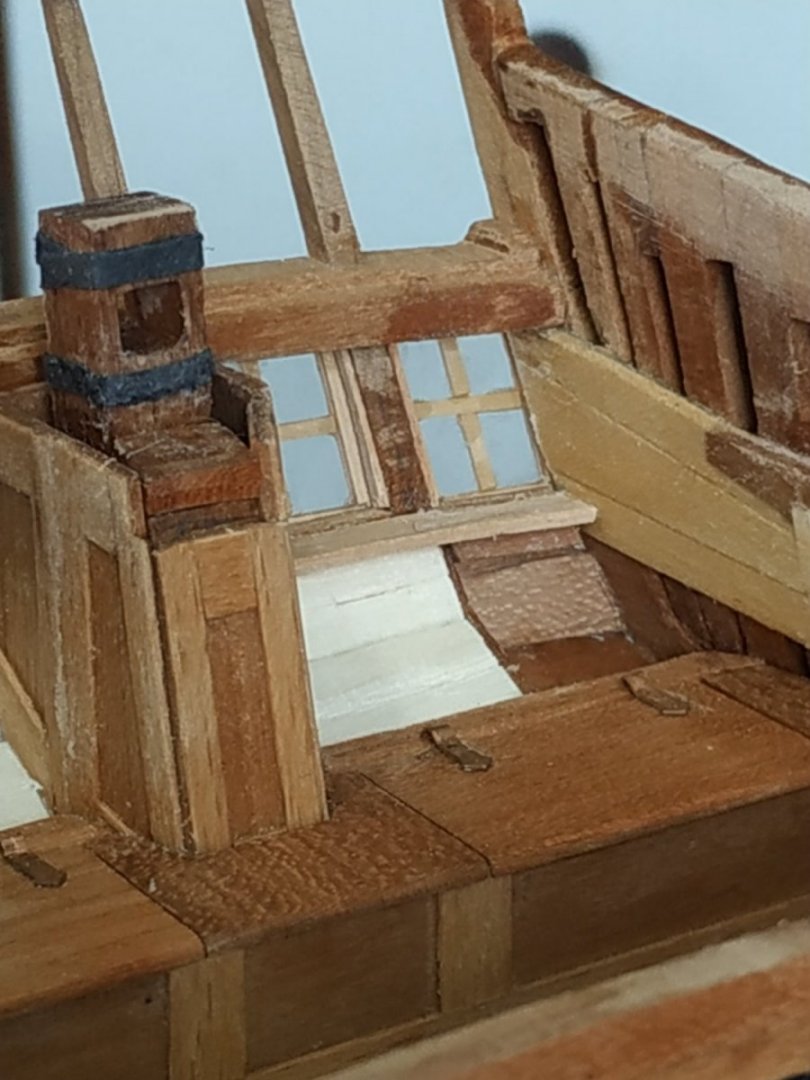
- 475 replies
-
- 11
-
-
Beautiful work. I made this as a first move from kits to scratch. You have done justice to this project.
-
Swan-Class Sloop by Stuglo - FINISHED - 1:48
stuglo replied to stuglo's topic in - Build logs for subjects built 1751 - 1800
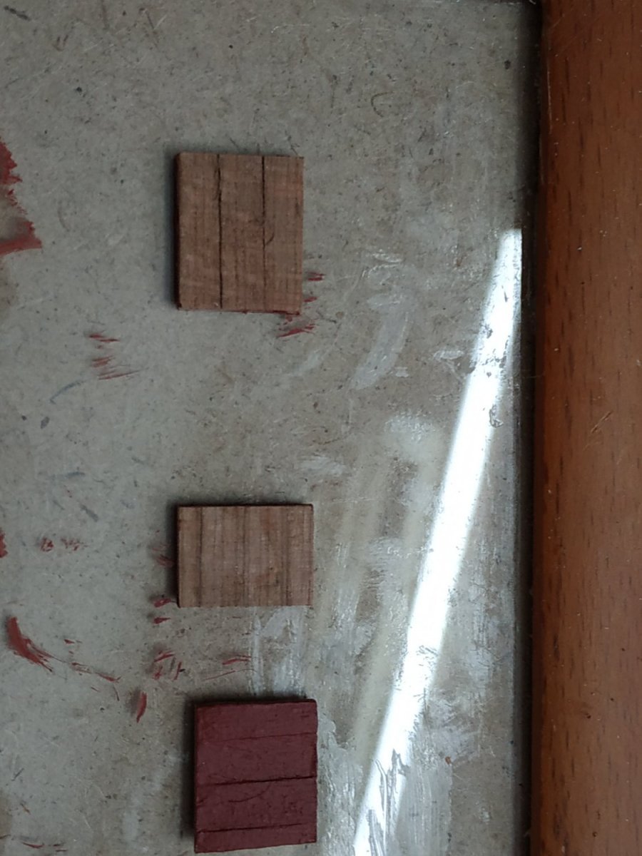
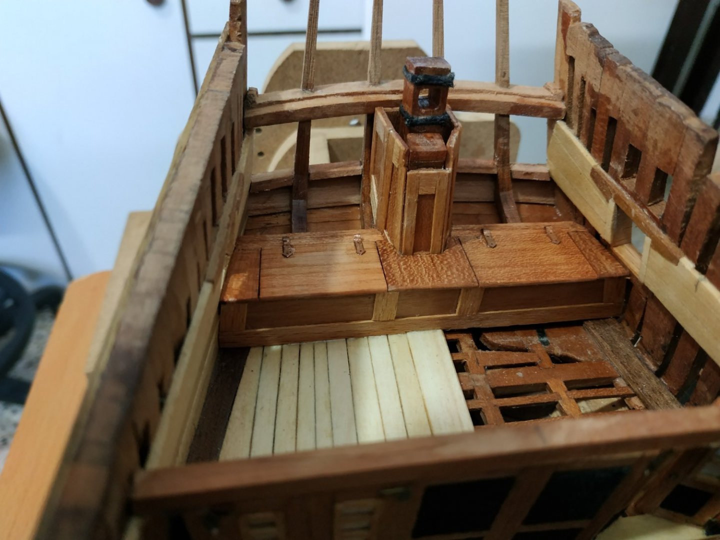
Internal Counter Planking and Lockers. Either side of the Rudder Trunk. A beam, triangular in profile,forms the straight edge for the lids and their hinges. I used a 4.5mm sq. blank, and sanded and scraped to shape. (Should have used a plane as it would have been easier.) Ensuring it is horizontal, at right angles to an imagined central line, top surface horizontal and lining up with its counterpart,while balancing on the curve of the counter timber, was not easy, but essential Perhaps fitting a plank first, would have made this easier. Anyway, “holding” with the PVA glue half dried and sticky, I managed after much frustrating fiddling. The locker front panel sits (athwartship) atop the deck planking. Its height is such that the lid, flush to the beam, sits on its top edge. Between the lids, in front of the Rudder Trunk, is a filler panel. There are also filler panels between the lids and hull. I made these next, but now realise it would be easier to make them after the lids are fitted. Hinges adapted from leftover port lid hinges from an old kit. (interesting that the wood of the lids look different although cut from the same piece with the grain in the same direction but fitted upside down.Without lacquer and photo, they looked the same.)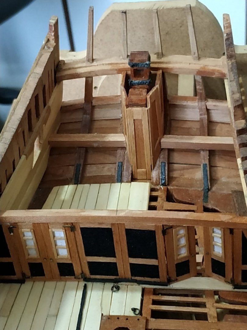
- 475 replies
-
- 14
-
-