stuglo
-
Posts
707 -
Joined
-
Last visited
Content Type
Profiles
Forums
Gallery
Events
Everything posted by stuglo
-
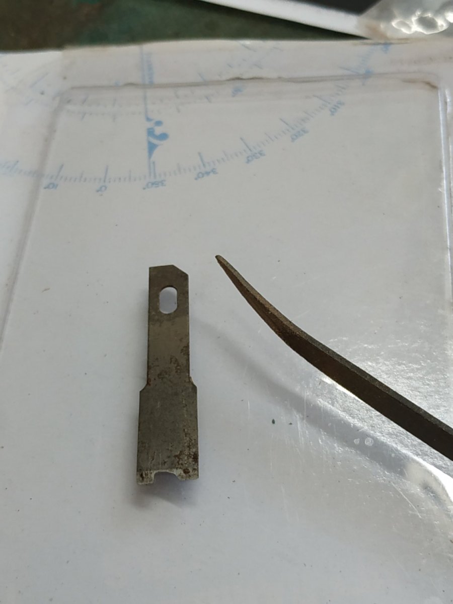
congratulations on the video milestone. 100 is a huge amount of work and a huge contribution to our community of model builders. The demonstration of soldering has encouraged me to try again. Until now I have tried many times and failed every one. By the way, what blade did you use to cut the brass?
-
Swan-Class Sloop by Stuglo - FINISHED - 1:48
stuglo replied to stuglo's topic in - Build logs for subjects built 1751 - 1800
Thank you. The additional detail and clarity is most useful. -
Swan-Class Sloop by Stuglo - FINISHED - 1:48
stuglo replied to stuglo's topic in - Build logs for subjects built 1751 - 1800
Please can you tell us how we can find this site - I googled it with 0 result -
Swan-Class Sloop by Stuglo - FINISHED - 1:48
stuglo replied to stuglo's topic in - Build logs for subjects built 1751 - 1800
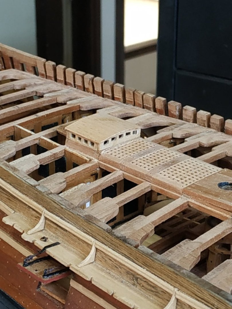
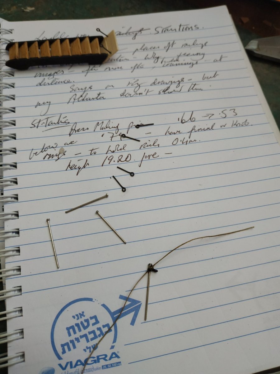
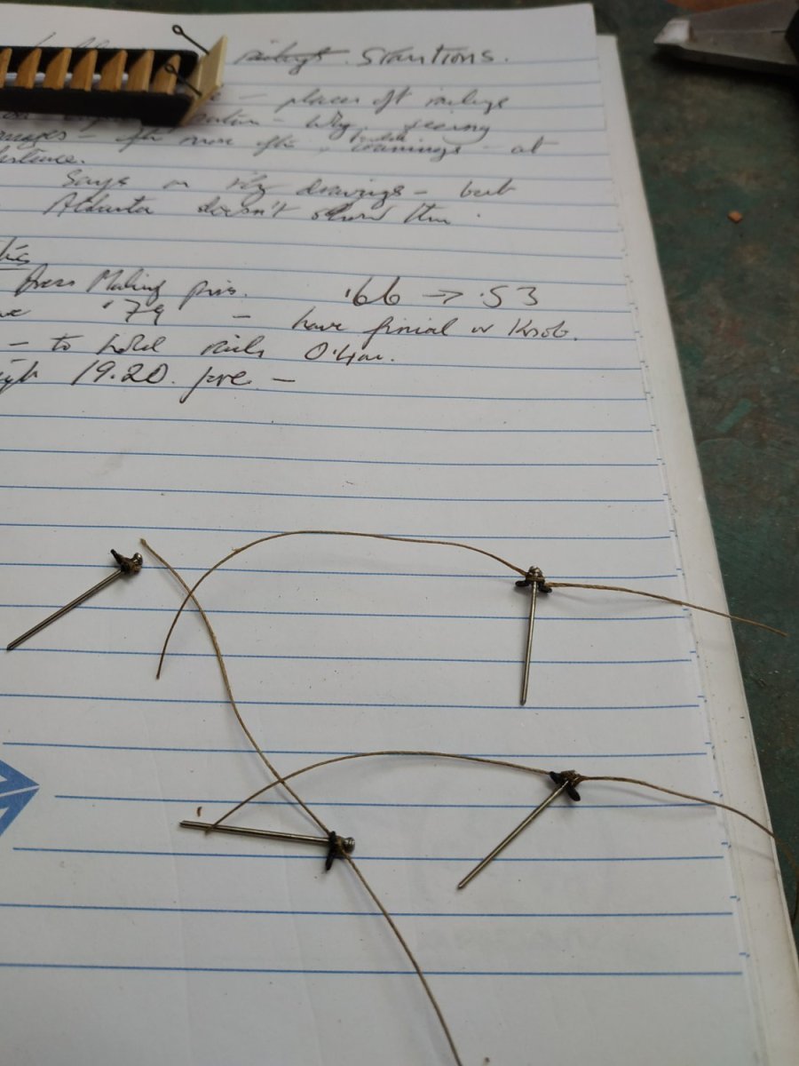
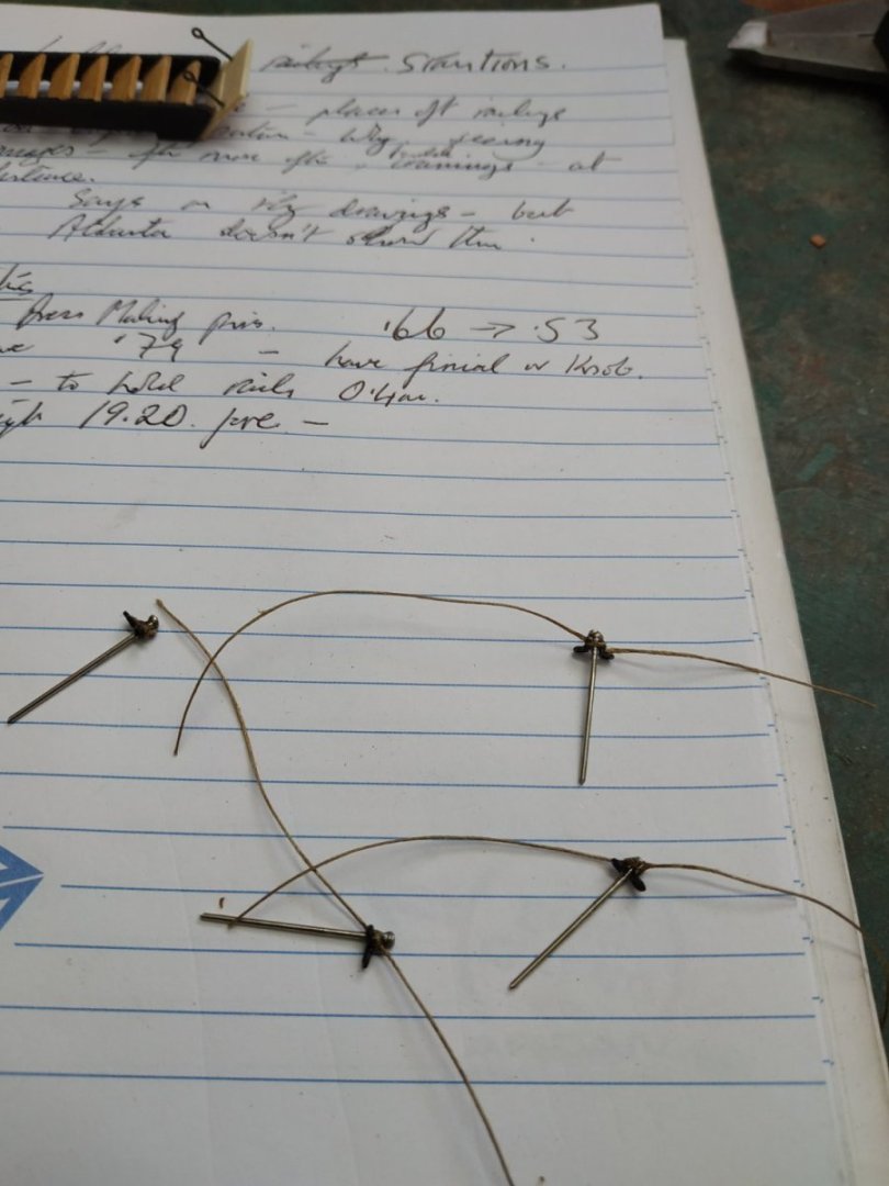
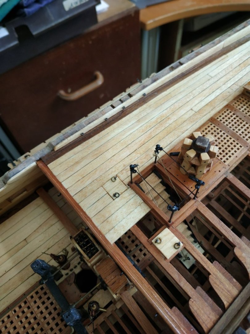
Ladderway Stantions, cont. Metal uprights, thickness 0.66mm tapering to 0.53 mm at the top, which is surmounted bi a Finial or knob. Height of forepair, 19.2mm- with a couple of extra mms to sit in the mounting holes. They are removable to allow fitting and use of the Capstan Bars. Below the Finial are a pair of rings, set into which the Rails (0.4mm) fit. At the opening of the stairs, the rope handrails are attached, the other ends of which are attached to bolts into the deck at the foot of the stairs. To see how it should be done, I refer you to the Dan Vadas blog. I took dressmaking pins (0.75mm), common kit eyebolts, bent at 45deg and shortened, glued and tied to the pin and spray painted them black. The rails, 0.4mm black-coated copper.
-
Swan-Class Sloop by Stuglo - FINISHED - 1:48
stuglo replied to stuglo's topic in - Build logs for subjects built 1751 - 1800
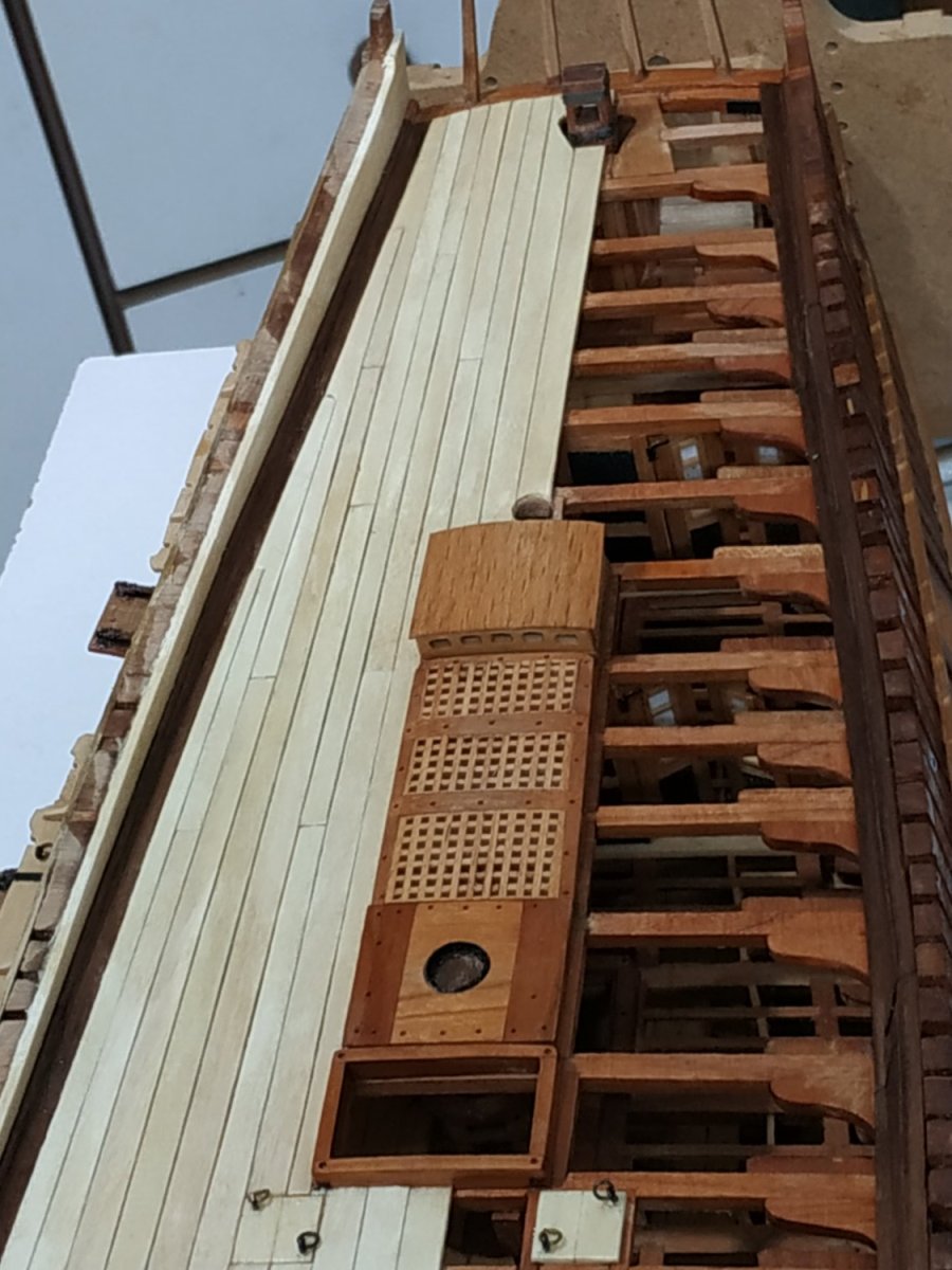
Ladder Way Stantions. My previous post was about the problems making the ladder. An additional reason was an “evil eye” (if you believe in such things) because, planning ahead, I decided to go against the TFFM (our bible) and not site the aft pair of stanchions on the capstan partners as suggested. Grossly ignorant in such things, it seemed illogical. The coamings were more often than not, at a distance from the partners (see google images and a few reference books). TFFM mentions the Fly plans. Stanchions are not shown on my Atalanta plans, but as an example of inconsistency, and therefore inaccuracy, the Capstan is shown parallel to the deck on the profile plans, and horizontal on the sheer plans. Could the Fly plans be wrong? Or am I missing something? ( I remember as a schoolboy, being taken to see one of several famous old bibles that had a printing mistake on display.)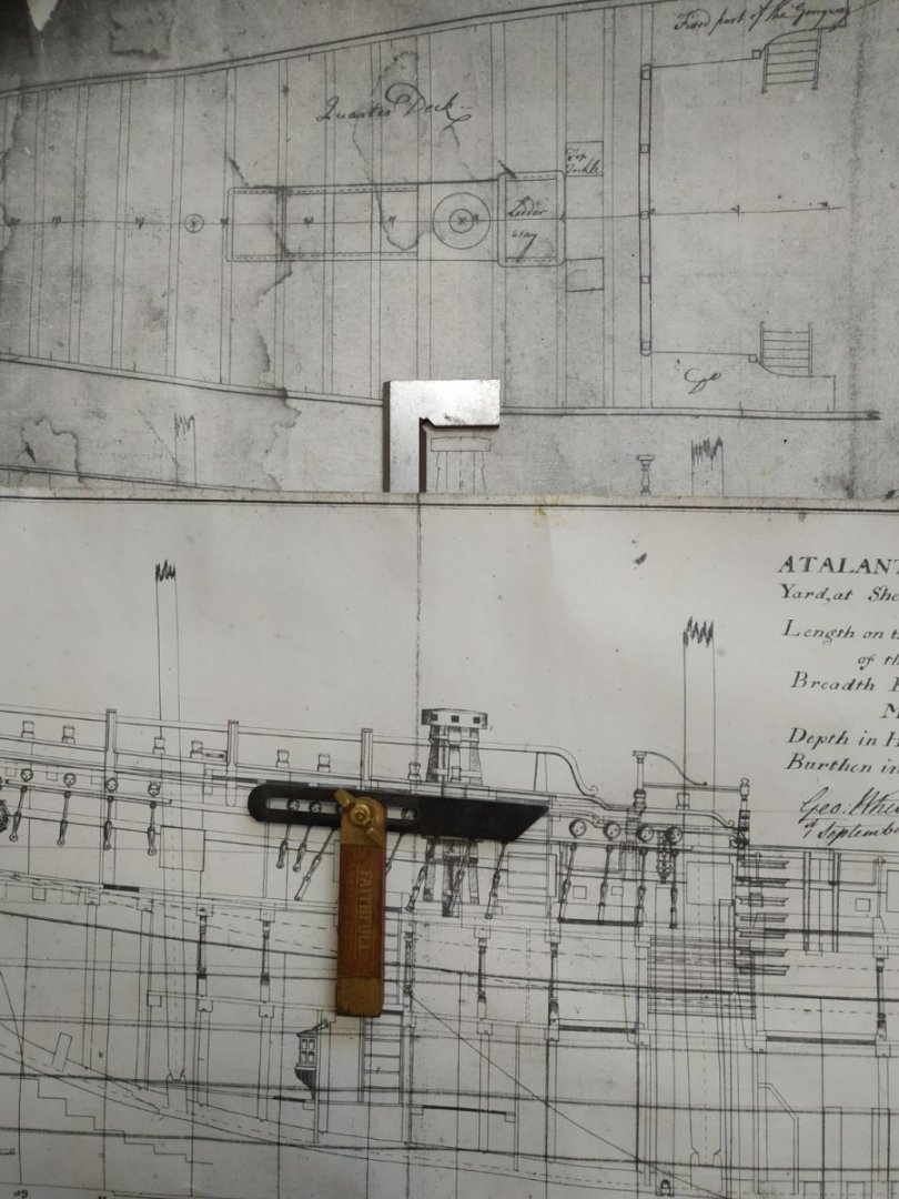
-
Swan-Class Sloop by Stuglo - FINISHED - 1:48
stuglo replied to stuglo's topic in - Build logs for subjects built 1751 - 1800
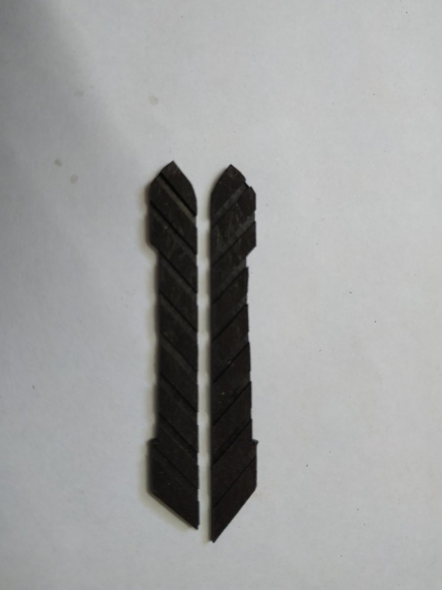
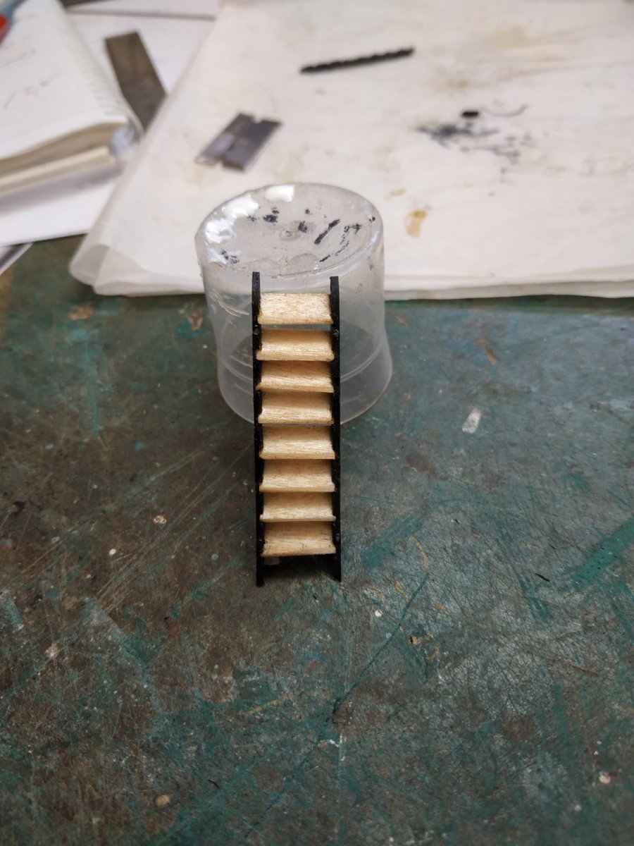
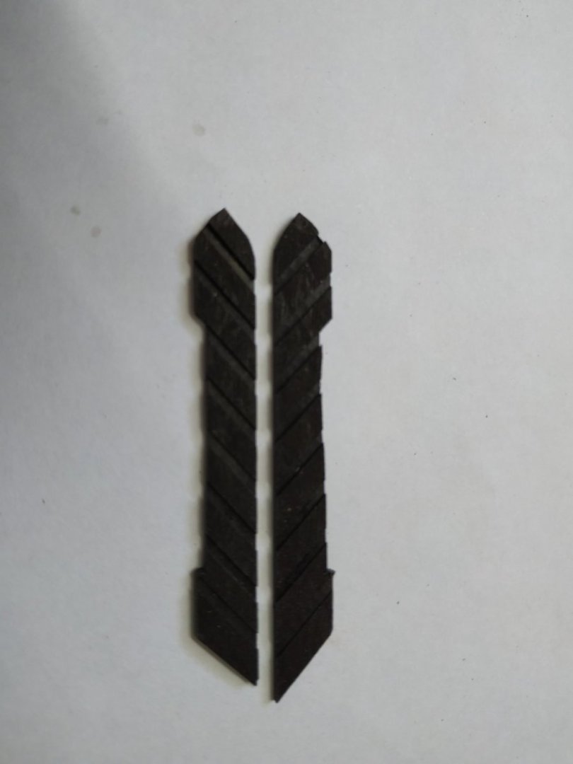
Quarter Deck Ladder Already made several ladders and wouldn't normally repeat a blog but - I can use the word DADO again 2) remark on my repeated failures to make a matching pair of Styles using the technique that was easy and so successful a few months ago. Only after some hours did I realise the “guide” was no longer fully fixed and the distance between the grooves varied, especially when the angle jig was reversed. Glued a new one. Lesson : worth checking the obvious when things go wrong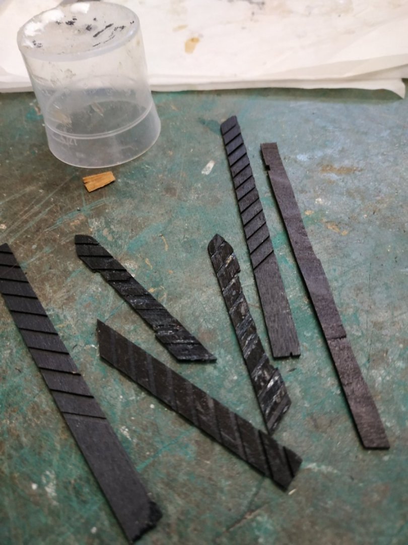


-
Swan-Class Sloop by Stuglo - FINISHED - 1:48
stuglo replied to stuglo's topic in - Build logs for subjects built 1751 - 1800
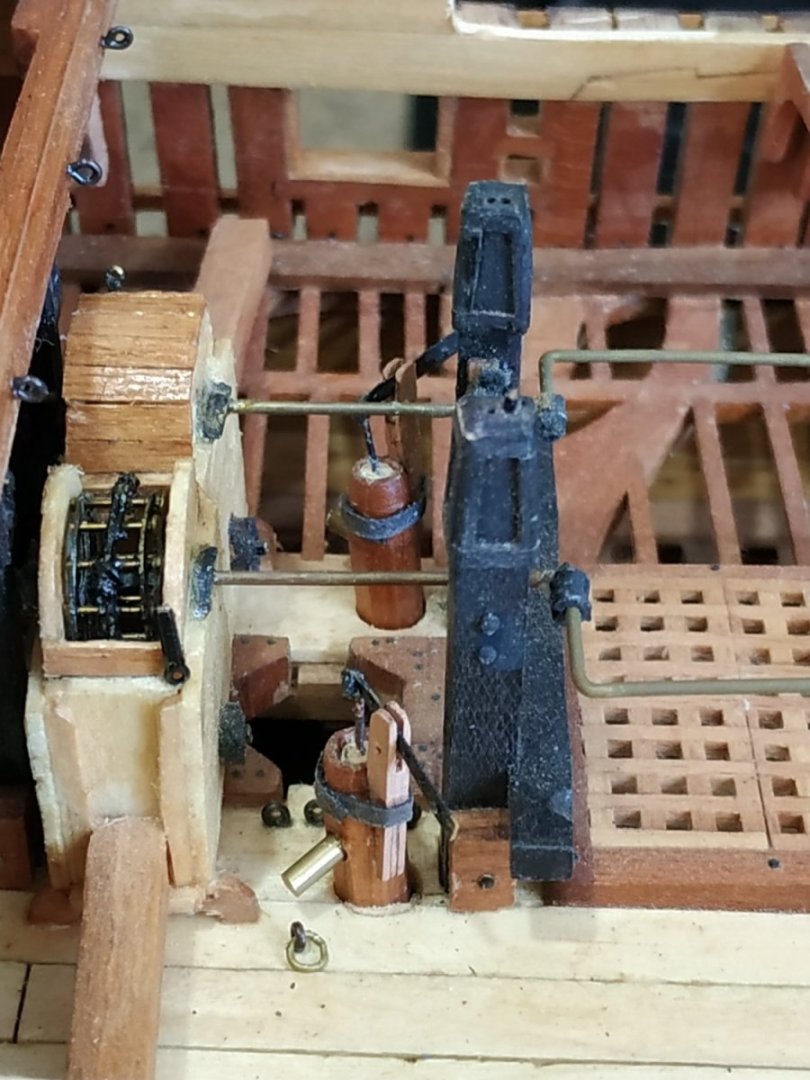
Brake Pumps, cont. Tubes previously made, delayed finishing to avoid damage. For the Fork - thin strips of wood -the lower ⅔ a “sandwich” Handle- a piece of spare copper blackened with sulphate solution Spear- eyebolt similarly treated-piecing a short wooden dowel acting as the upper box/ Iron Band-black thick paper.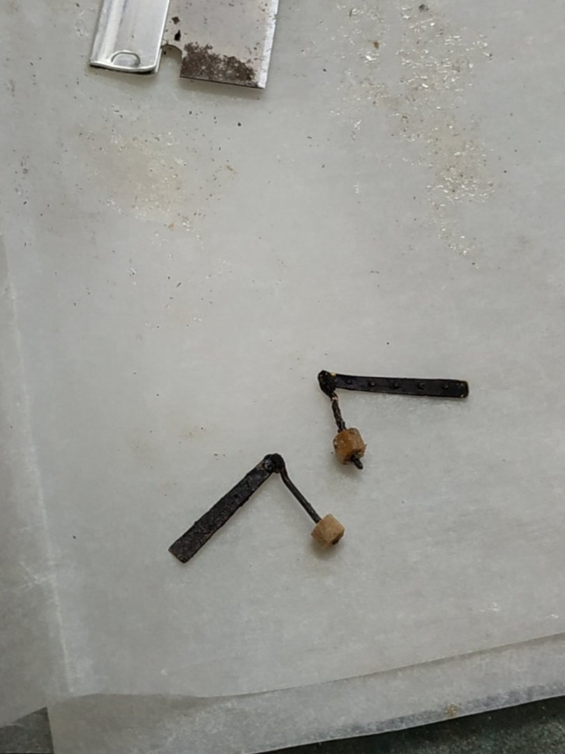
-
Swan-Class Sloop by Stuglo - FINISHED - 1:48
stuglo replied to stuglo's topic in - Build logs for subjects built 1751 - 1800
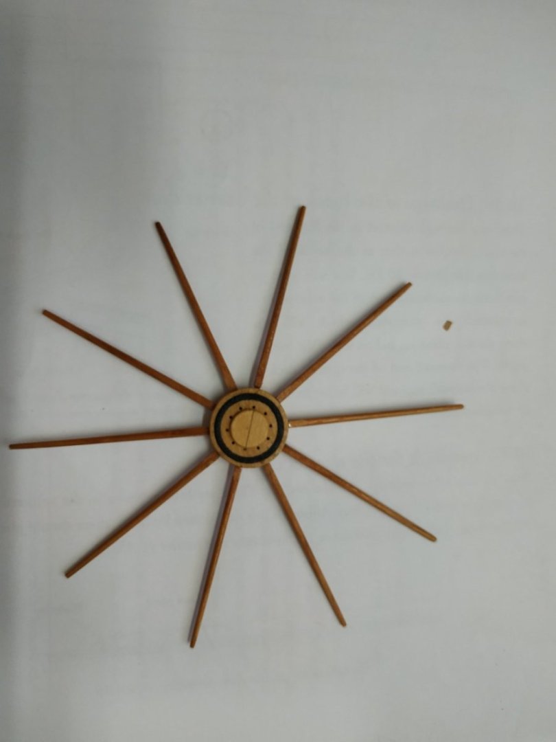
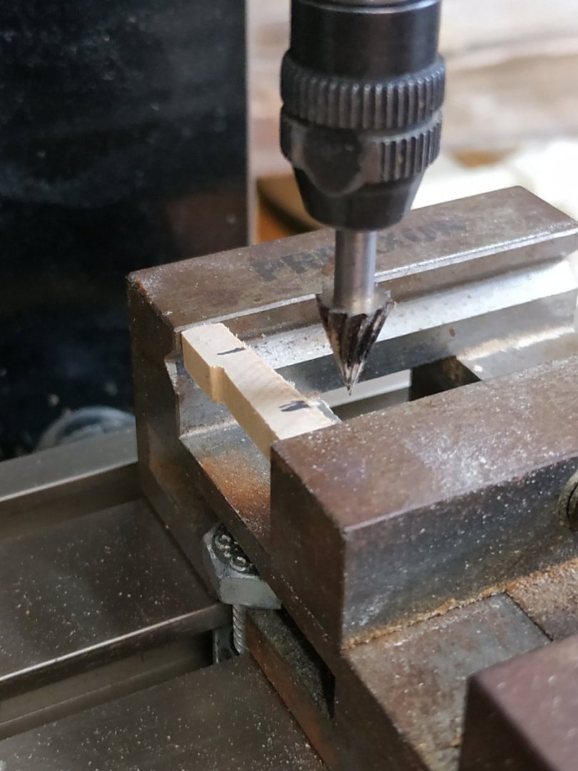
Upper Capstan cont. Capstan Bars. Bars are 54mm long but otherwise the same as the Lower Capstan Bars. The inner end,from shoulder 1.99 tapers to 1.38. The outer (long) end also tapers to 1.38mm but is chamfered and rounded for most of its length. (lathe and sandpaper strips) Although not shown, other images, including the 3D rendering, show a thin central cap on the upper surface of the capstan. This I added. Also as per Lower Capstan has a pair of Capstan Pawls. These I made from wood (Previously for the LC, use some blacked copper. I intend to fit the Drumhead and Bars at end of build- they are very vulnerable

-
Swan-Class Sloop by Stuglo - FINISHED - 1:48
stuglo replied to stuglo's topic in - Build logs for subjects built 1751 - 1800
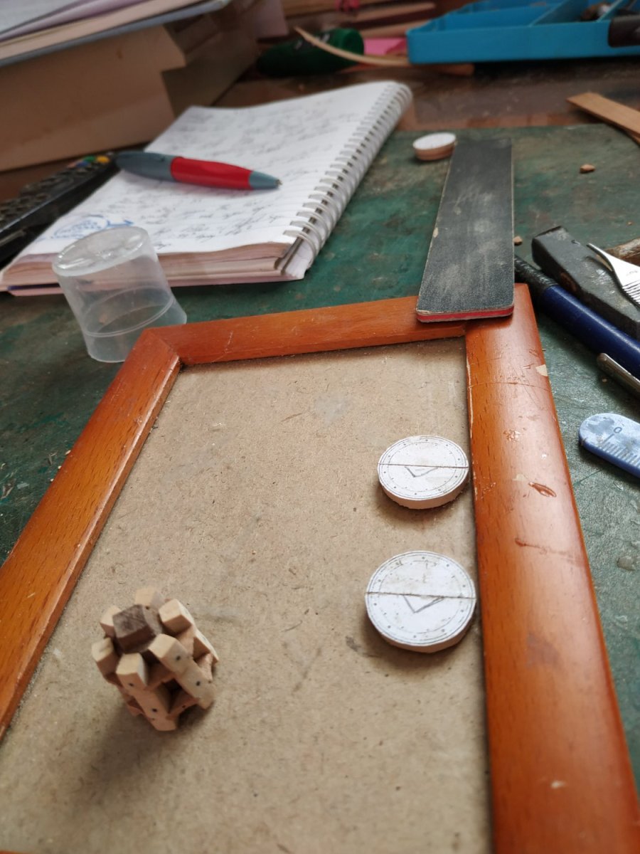
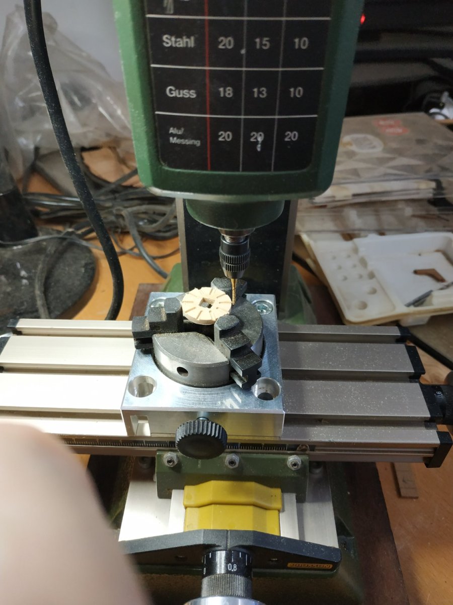
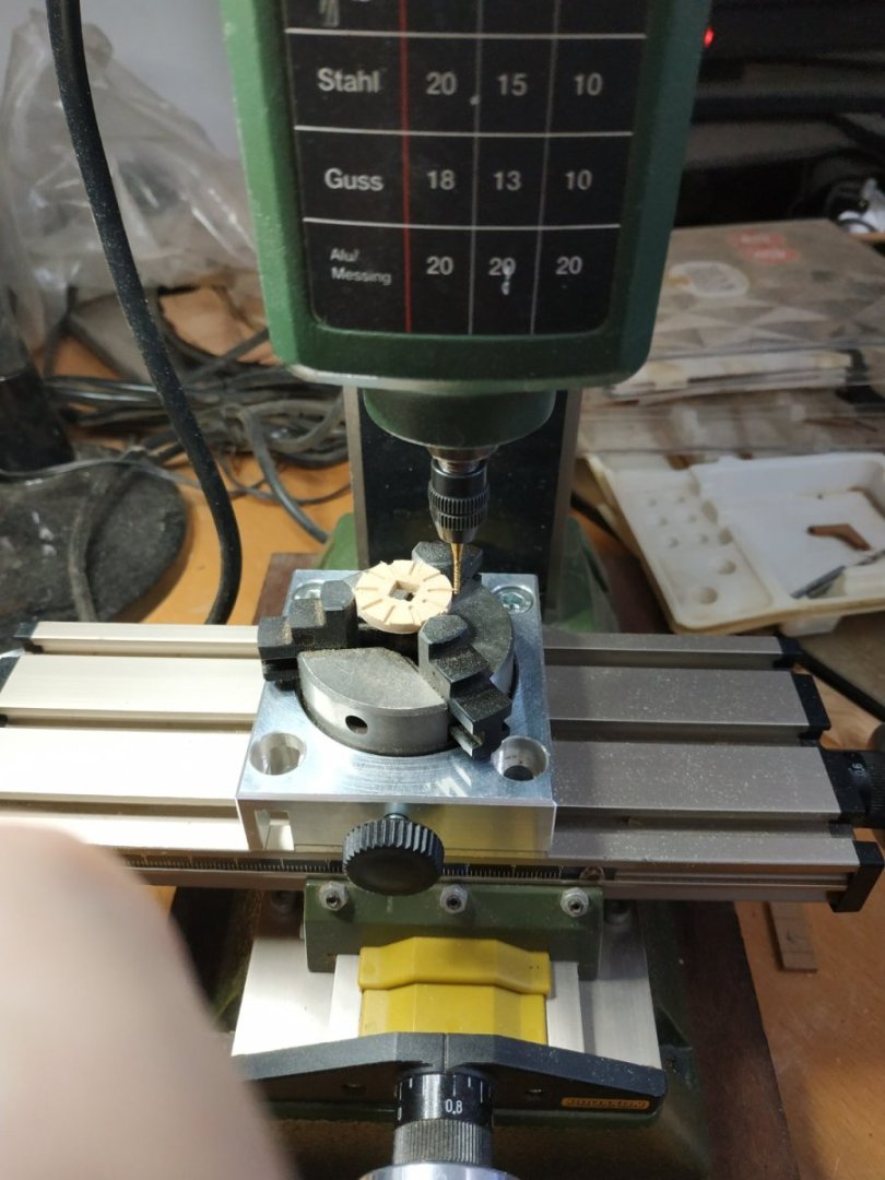
The Upper Capstan, cont. The Drumhead. Again, 2 layers- upper 3.05mm, lower2.65mm. Each formed by joining 2 halves. The Tenon of the Lower Spindle passes through the lower layer and is mortised by 0.8mm into the upper layer. Unlike the Lower Capstan, there are 10 Bars, and the surfaces therefore needed to be scored. I first cut out the hole and made the mortice with the mill, files and blade. The part of the bar to be inserted is 5mm long, 1.99 sq. tapering to 1.38mm sq. The TFFM illustration shows a “shoulder”. Google images show most without, but after making them, Iput in this shoulder because I deliberately made the scores undersize, to allow fof later adjustments where the upper and lower layers meet exactly. I’ve had this problem before, even with the Proxxon Dividing Head. In theory, it should be easy. Just divide 360degs. by the number of Bars and turn the Head. I used a 1.3 bit, but errors occurred when eying the divisions. ******** I found that the head “creeped” around a degree or 2. Presumably the movement of the bit caused this. If the screw stopping this rotation is used to stop this, I worried the clamps of the chuck would loosen. I stabilised with a finger grip, but there must be a better solution.****** I omitted the scoring on the underside for the whelps. The Iron Reinforcing Rings are platted thread, 1.7x0.2mm and fitted into both upper and lower surfaces with the mill dividing head. I drilled the 10 holes for the Retaining Pins, by fitting the dividing head to my drill press.
-
Swan-Class Sloop by Stuglo - FINISHED - 1:48
stuglo replied to stuglo's topic in - Build logs for subjects built 1751 - 1800
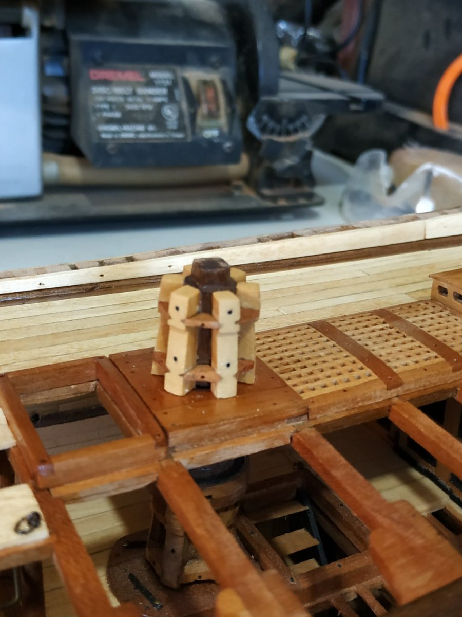
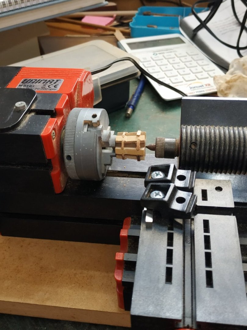
Upper Capstan. Connected to the Lower Capstan’s spindle, through the quarterdeck Capstan Partners. Some differences from the L.C. build.(Spindle previously made along with its lower counterpart.) The Whelps- height 19.1mm, wedge shaped section- width 3.9mm outer and 2.9mm inner. Depth at base 4.9mm tapering to 3.4 mm at top.-”dog leg” about ¾ of the way. I used MAGIC WOOD (otherwise known as boxwood). It really is fantastic. Imagine a whole model with the stuff ! I shaped the tapering with the mill and sanding board. I also milled the scores for Chocks. The upper chock is 1mm, the lower1.66mm. The Upper chock has a convex outer edge- the Lower is concave. After assembly and gluing, turned the whole on a lathe to form outer curve on whelps and chocks, and used a sanding stick. The concave edge of the Lower Chocks then formed with a round file.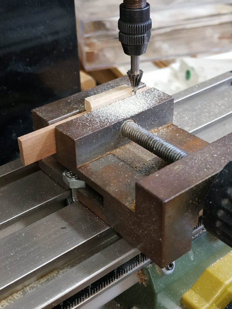
-
Swan-Class Sloop by Stuglo - FINISHED - 1:48
stuglo replied to stuglo's topic in - Build logs for subjects built 1751 - 1800
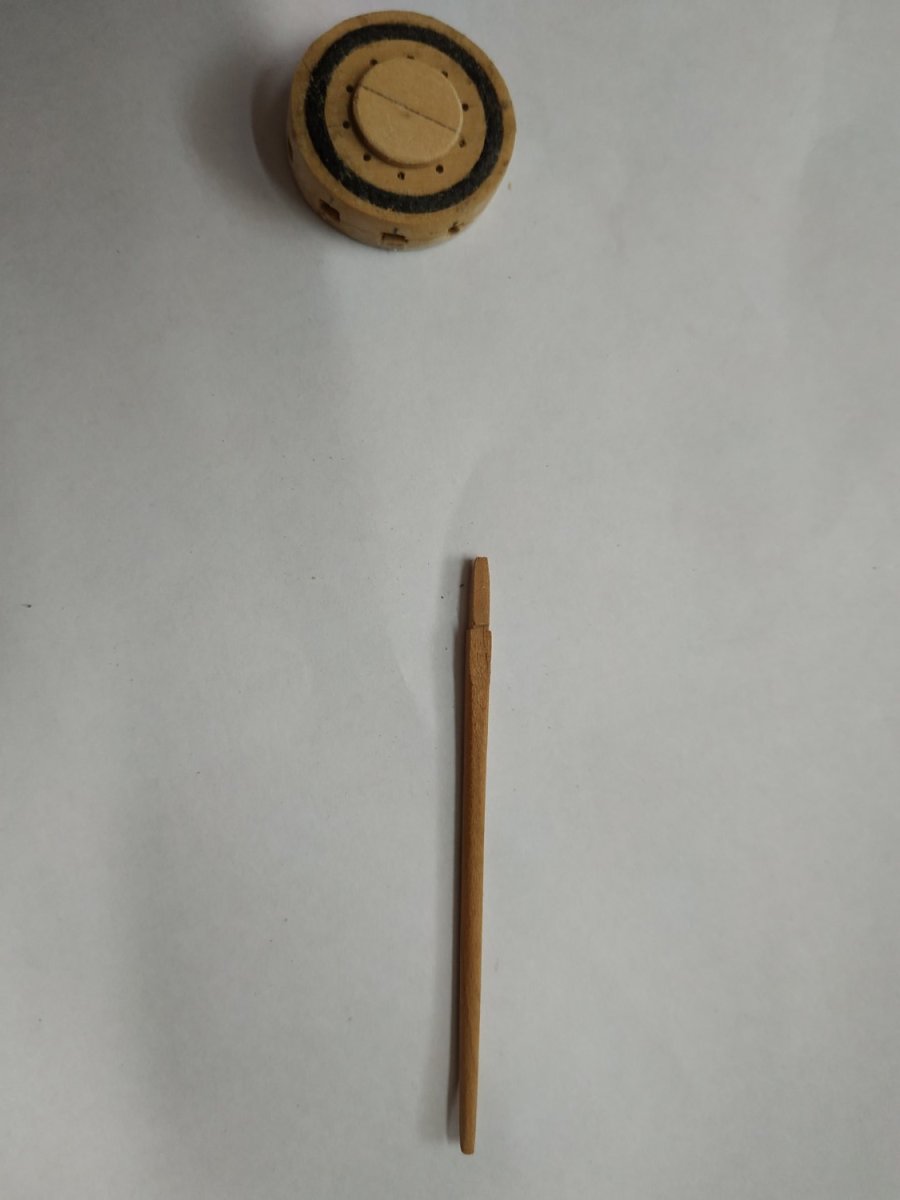
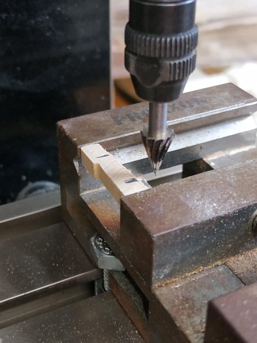
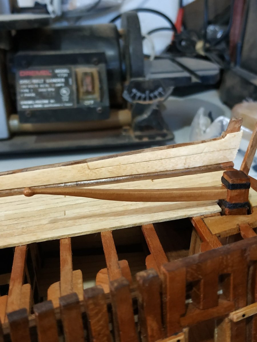
The Tiller. Given choice of Tiller with or without a Steering Wheel My Atalanta plans do not show a Wheel. A Steering Wheel is very delicate and complicated. Even if I had the ability, I lack the patience at this stage of the build. The aft end is a tapered square, 4.77x3.71 to fit into the mortise of the Rudder Head. Foreward, it curves and tapers, with increasing champhing, until rounded. At the very end, it expands into a small ball. Made from some local pear wood. Using a blank and the patterns printed in TFFM.
-
Swan-Class Sloop by Stuglo - FINISHED - 1:48
stuglo replied to stuglo's topic in - Build logs for subjects built 1751 - 1800
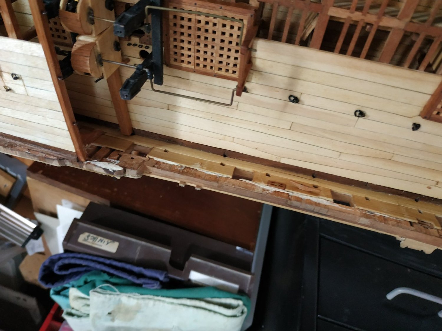
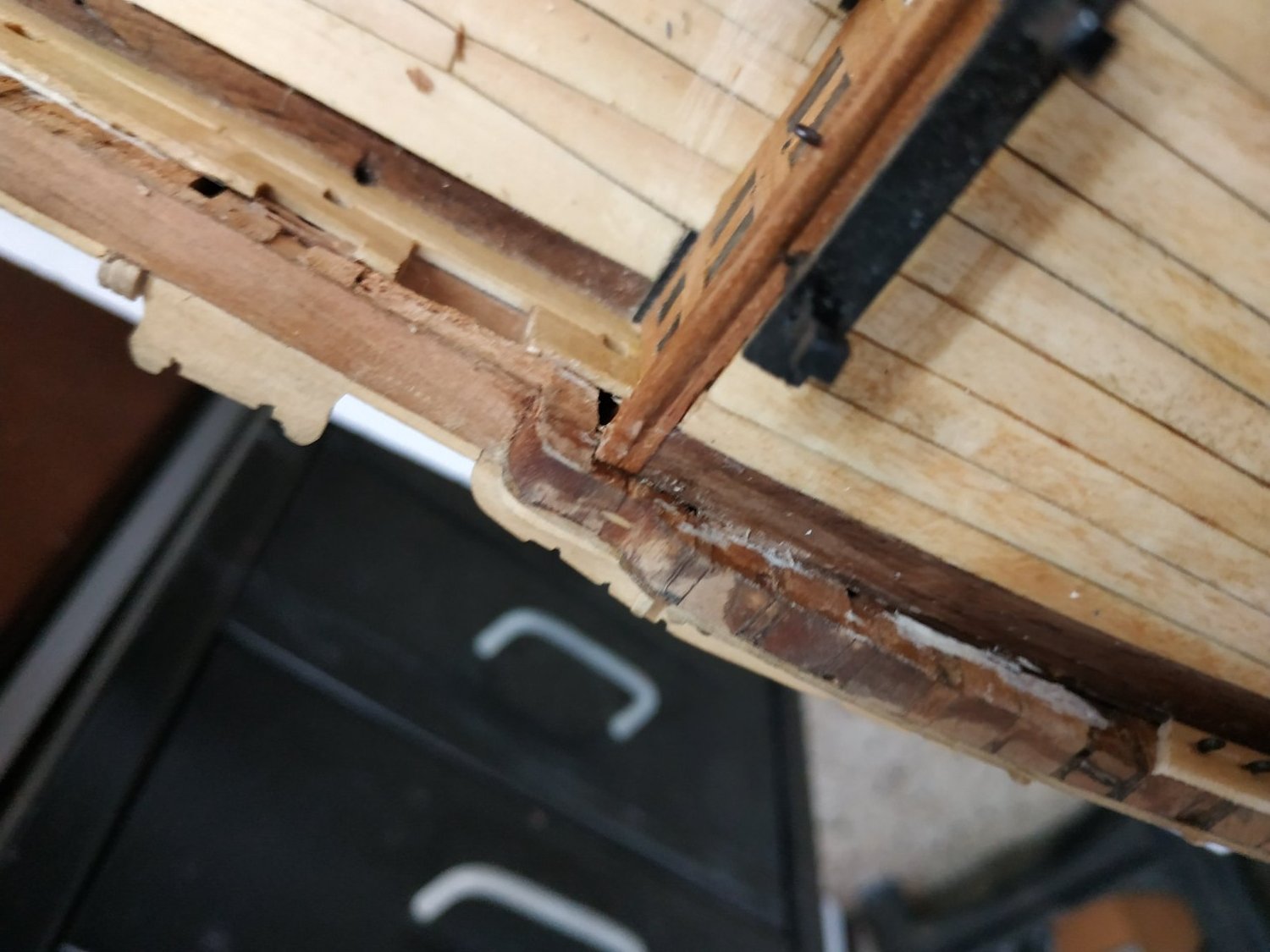
Replacing inner planks - colour difference, before poly application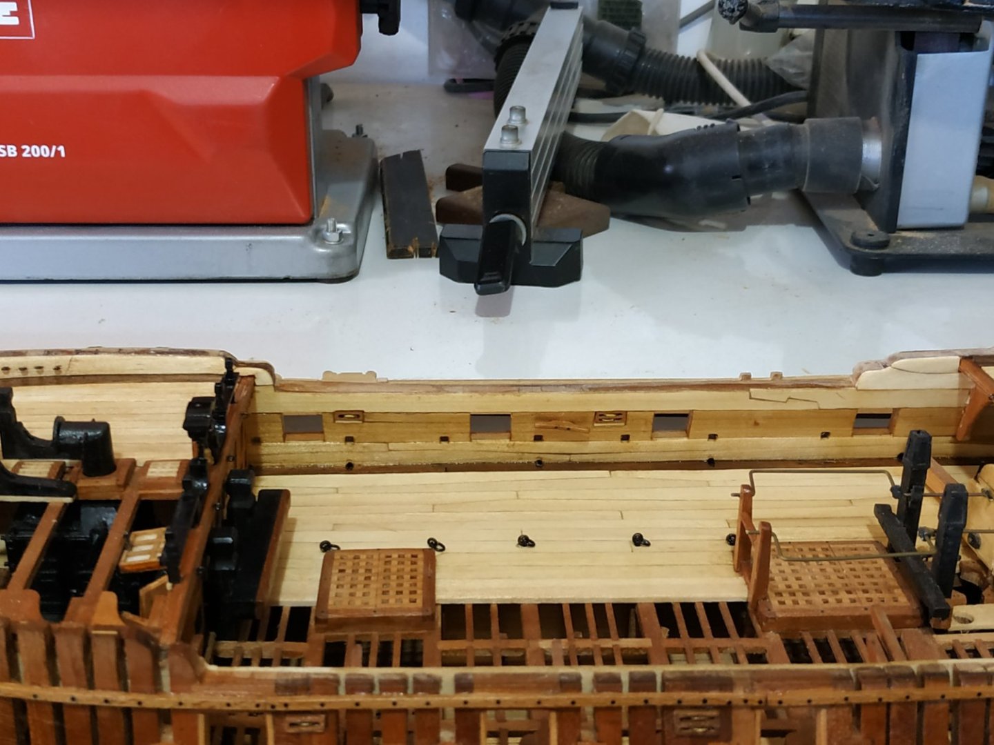
-
Swan-Class Sloop by Stuglo - FINISHED - 1:48
stuglo replied to stuglo's topic in - Build logs for subjects built 1751 - 1800
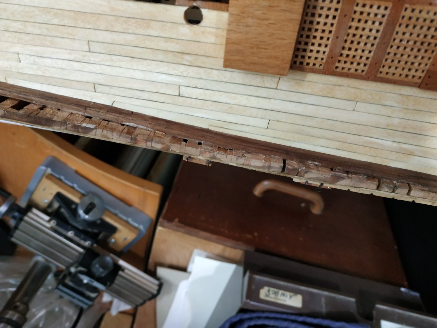
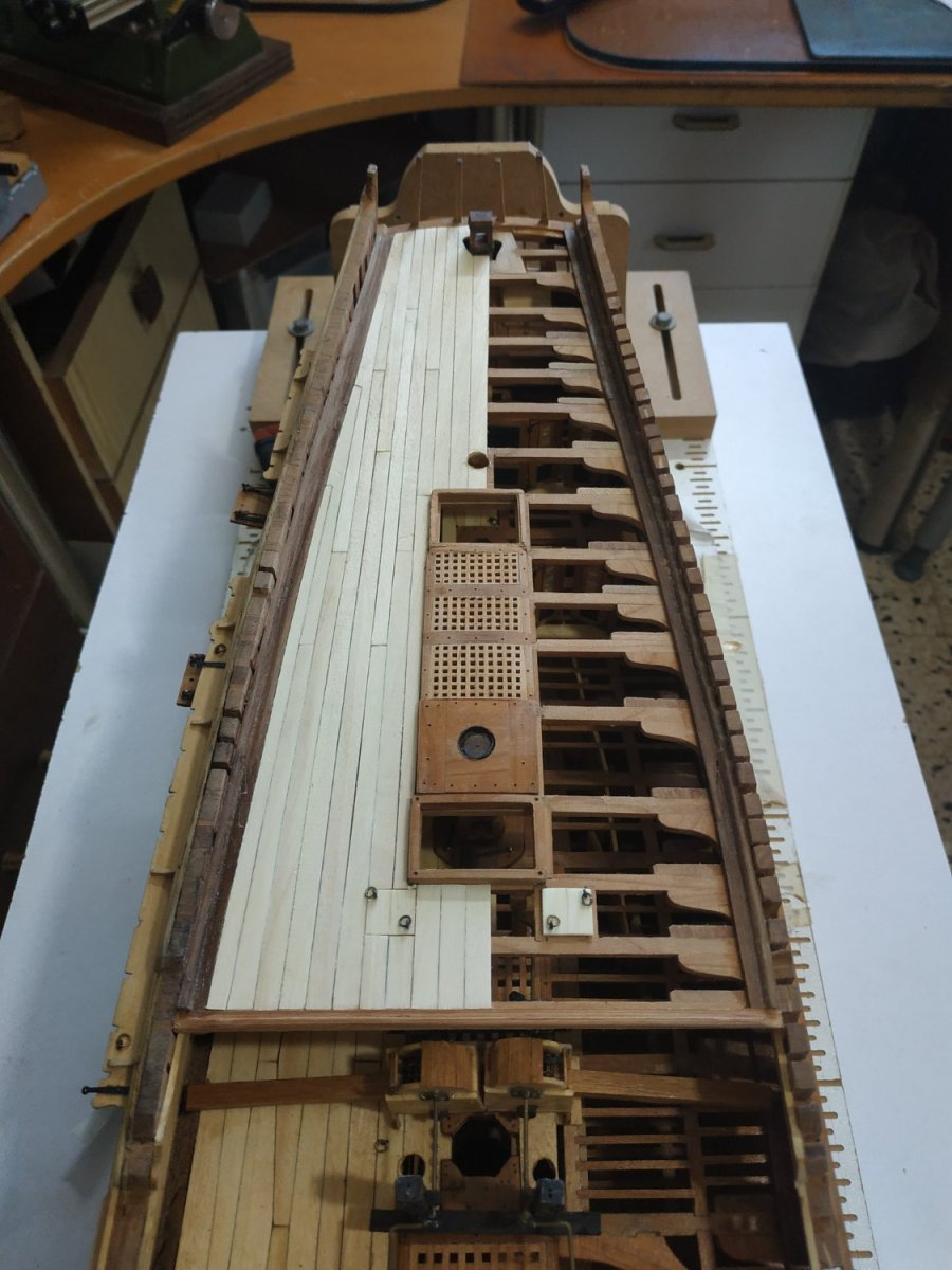
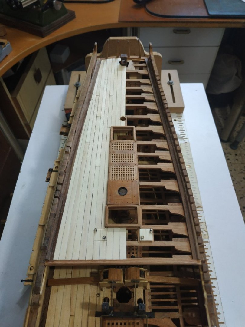
Thinning Down the Hull. As mentioned in a previous post, this is too thick. Not wanting to undo and redo the outer planking and structures built, settled on just removing the 2 upper inner planks, thinning the ribs as much as possible, and then replacing them. Because of some change in angle, these also needed to be sanded flush. By no means perfect but will later be disguised by the Gangway.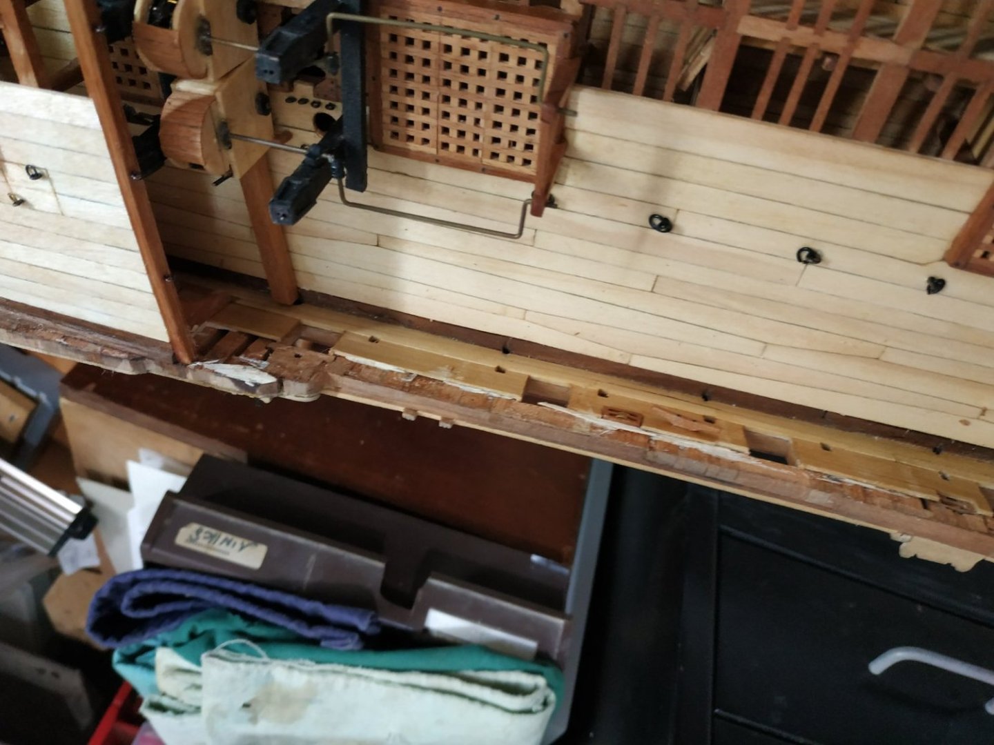


-
I find the patterns excellent GUIDES, but unlike the plans, the book (or my building) needs some adjustment.
-
Proxxon tools are good, but for a bench press I bought a chinese online for just over 100$ and bought an X-Y table which was easily adapted. It works fine for me. Anyway, its one of the essential tools.
-
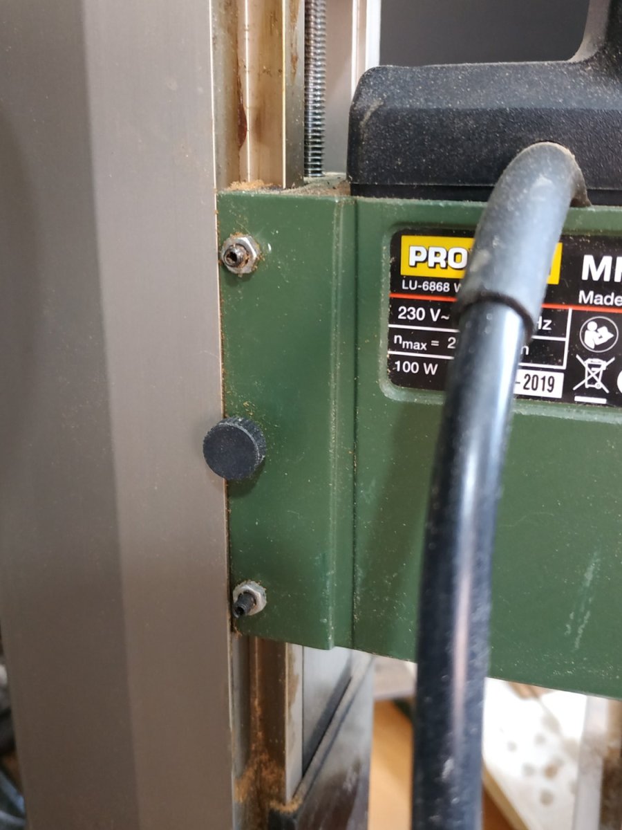
HELP !!. MF 70 Proxxon Mill problem
stuglo replied to stuglo's topic in Modeling tools and Workshop Equipment
PS - if the adjustment screw are (too?) tight, this results in play in the handwheel. -
HELP !!. MF 70 Proxxon Mill problem
stuglo replied to stuglo's topic in Modeling tools and Workshop Equipment
I found solution. Adjusting screws on side. No patients-ADD
-
A few days ago, I noticed some 1mm play (vertically) between the Main Housing and Z Pillar. ? diagnosis and treatment I can try a home. I use it daily, and don't want to send it for repair.
-
Swan-Class Sloop by Stuglo - FINISHED - 1:48
stuglo replied to stuglo's topic in - Build logs for subjects built 1751 - 1800
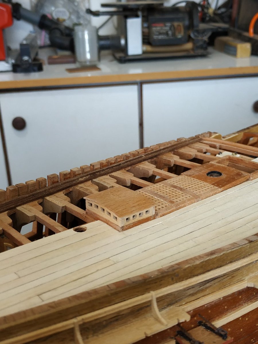
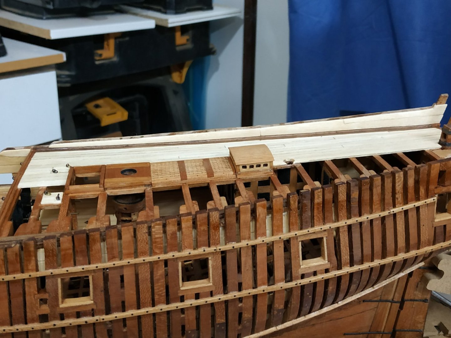
Quarter Deck Planking. Thickness 1.33mm. Tapers aftward. Scuttles- single each side, made as before-lower of 2 layers of plank at right angles. Remade the Companion Top (including plastic lights) Quarter Deck Bulwark Planking. (#27,#28) 1.66 thick. Note- starts about 10mm aft of Breast Beam, with raise of Hull line. *********************************************************************************************** Major Mistake/Problem. The hull ribs are too thick. Particular;y at the waist. Suspected and then forgot before I applied the inner and outer planking. Looking ahead to the Planksheer this became obvious. I thinned down the port side (4mm), but I don’t want to remove the planking on the starboard side. Any advice is most welcome. ***********************************************************************************************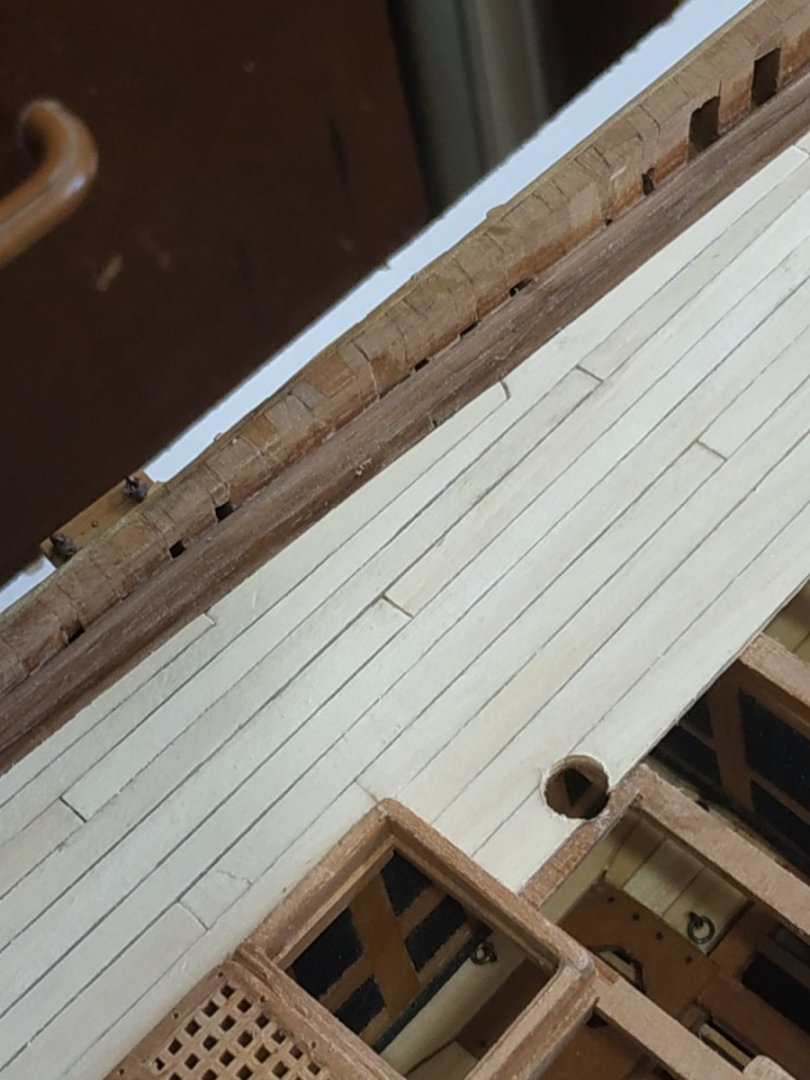


-
Swan-Class Sloop by Stuglo - FINISHED - 1:48
stuglo replied to stuglo's topic in - Build logs for subjects built 1751 - 1800
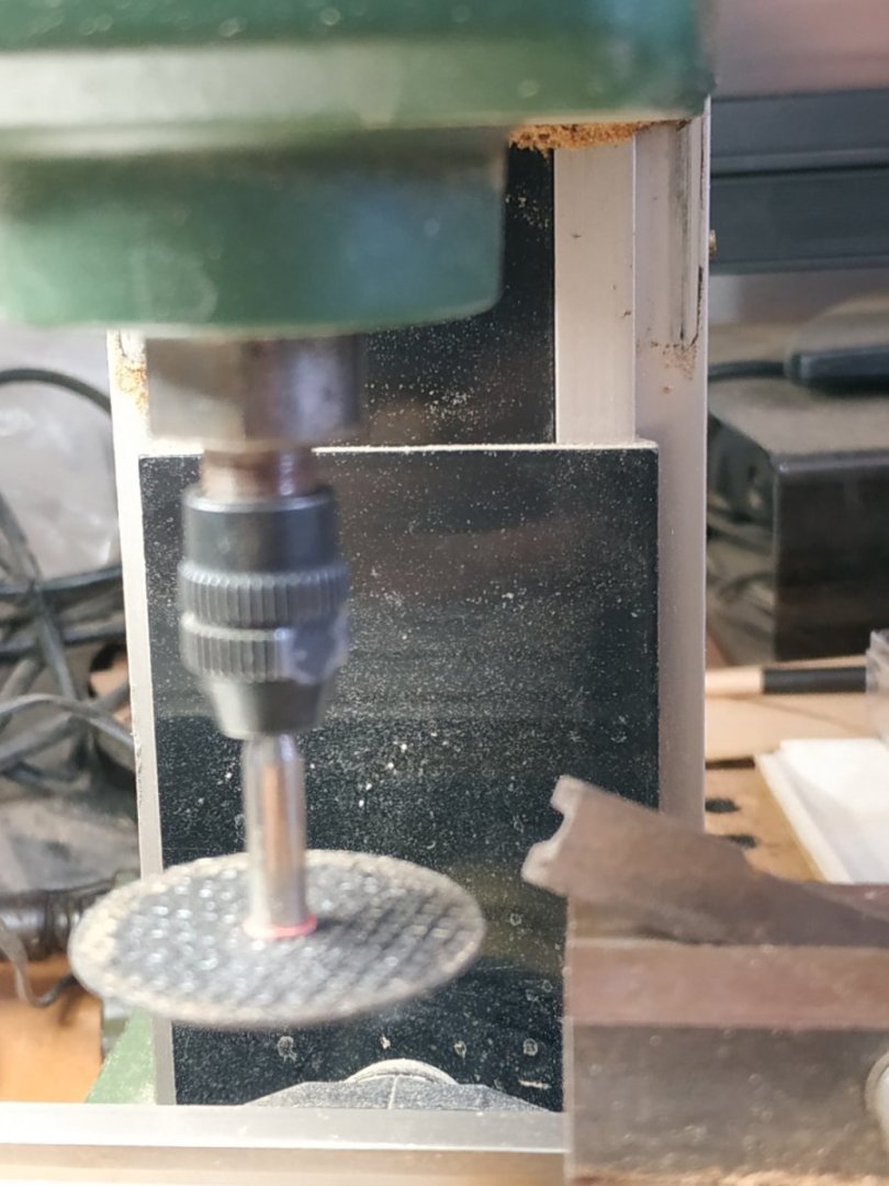
Quarter Deck Waterway 6.36wide and max height 2.12. Tried a different way. As suggested for the Breast Beam, made in 2 parts. The “flat” 6.36X 1.33mm (thickness of planking). Shaped the molding with a bespoke scraper. I did not need to anneal the blade- the disc in the mill had no trouble cutting it. After gluing it to the base, final shaping with another homemade scraper and a small riffler file.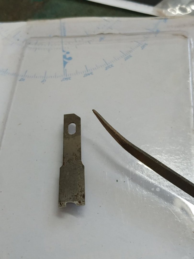
-
Do-It-Yourself Thicknesser
stuglo replied to stuglo's topic in Modeling tools and Workshop Equipment
Well, I said I'll try your "Y" table suggestion. I adapted the pervious attempts by simply screwing the lower plate to the base on the "Y" screw, while maintaining the ability to raise the upper plate by screws. The "Y" gives, I think, finer tuning.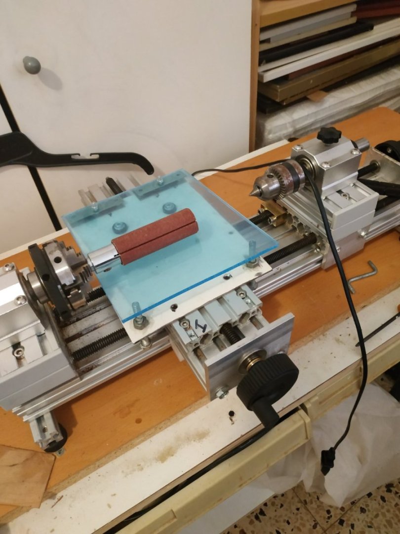
-
have you tried using bamboo tooth picks? they fit into draw plate and can be drawn or pushed while rotating in a drill
-
Are you just using the sharpened point then sharpening again for each treenail? If so, it seems more work than producing the required diameter over the whole length, with use of drawplate or "drill" method.
-
Swan-Class Sloop by Stuglo - FINISHED - 1:48
stuglo replied to stuglo's topic in - Build logs for subjects built 1751 - 1800
Companion Top. Some discussion in TFFM on style appropriate for type and age. A clerestory type is illustrated. The coamings for the base are already in place .Height 5.5mm including rounding up 1mm. A veneer “sandwich” with “glass” filling was again suggested, as was used for Bulkheads. There are small openings for the lights, which I found impossible to make without breaking the walls. I then tried using some thin boxwood 1.10mm as a single layer - more successful. I used the veneer for the roof as a single piece, but the grain gives the appearance of narrow planks. When all dried, I realised I left out the “glass”. Maybe return to put things right when I’ve more patients. One of those (superficially) simple builds that are ultimately most frustrating.