stuglo
-
Posts
707 -
Joined
-
Last visited
Content Type
Profiles
Forums
Gallery
Events
Everything posted by stuglo
-
I hesitate to add anything to the foregoing experts. These are models and subjective opinion has a place. I personally prefer a subtle not a "measles" appearance. Your proven expertise will, I'm sure, produce an excellent result. Might I just suggest a small, parallel, build to rest from a repetitive and possible boring few days (Reduced alertness=mistakes)
-
Swan-Class Sloop by Stuglo - FINISHED - 1:48
stuglo replied to stuglo's topic in - Build logs for subjects built 1751 - 1800
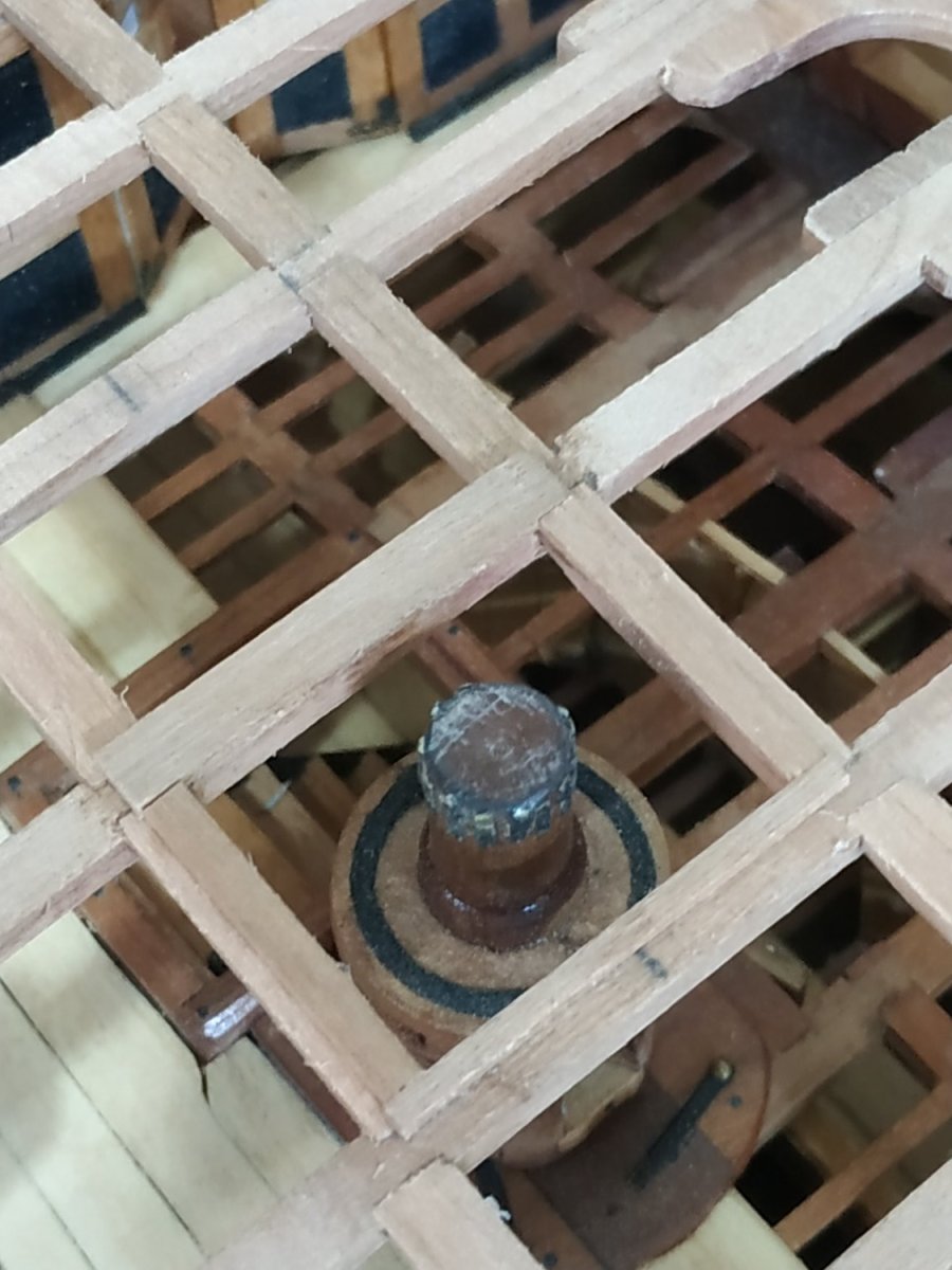
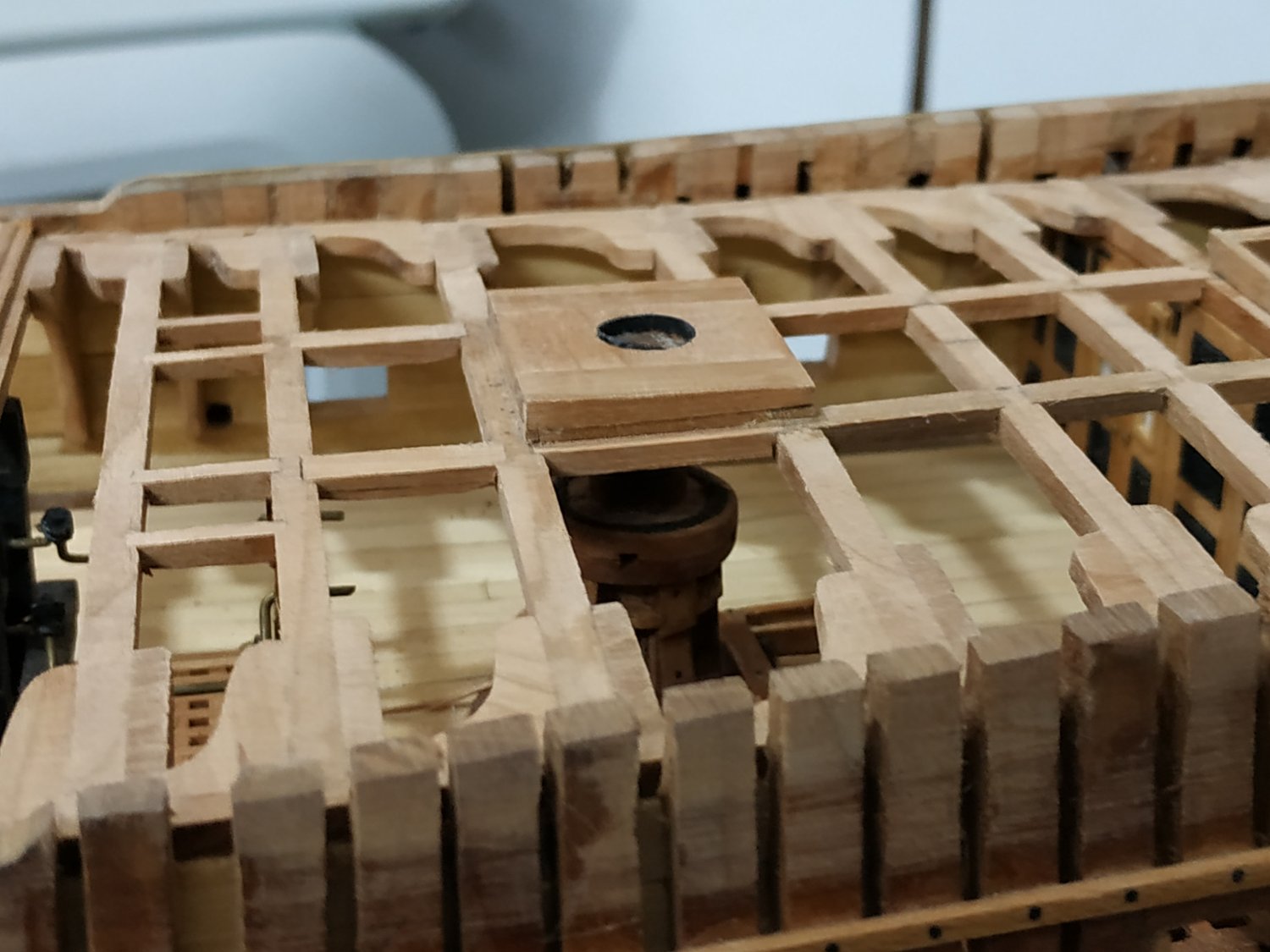
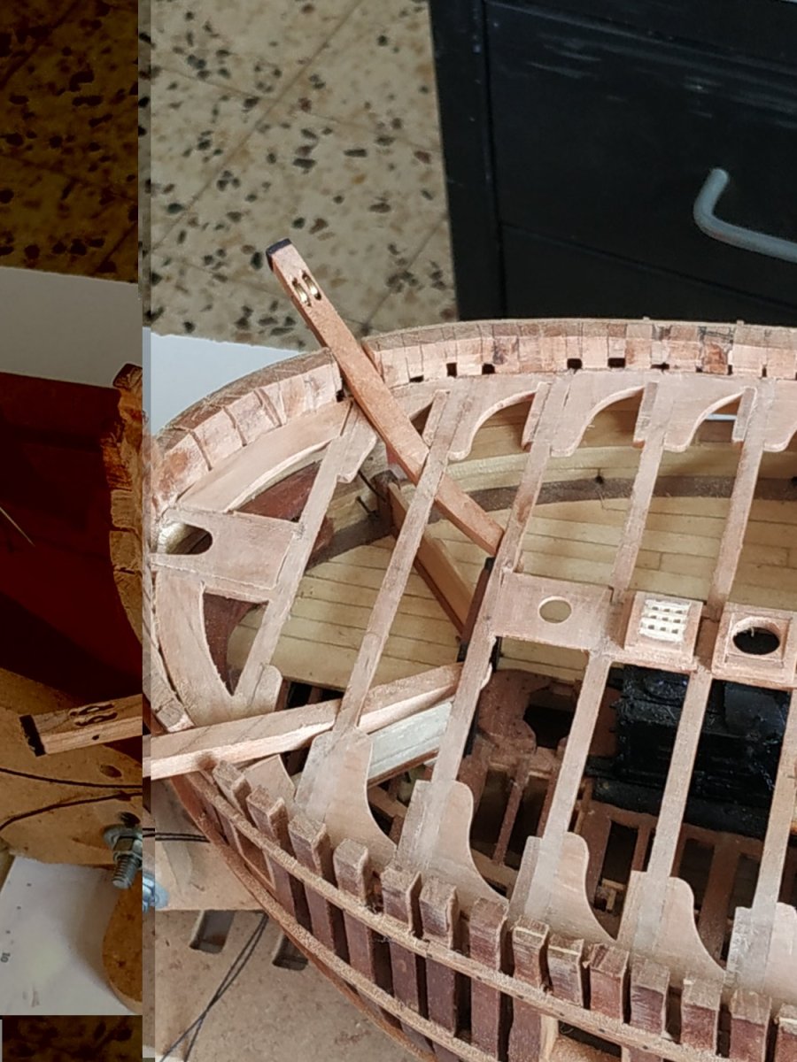
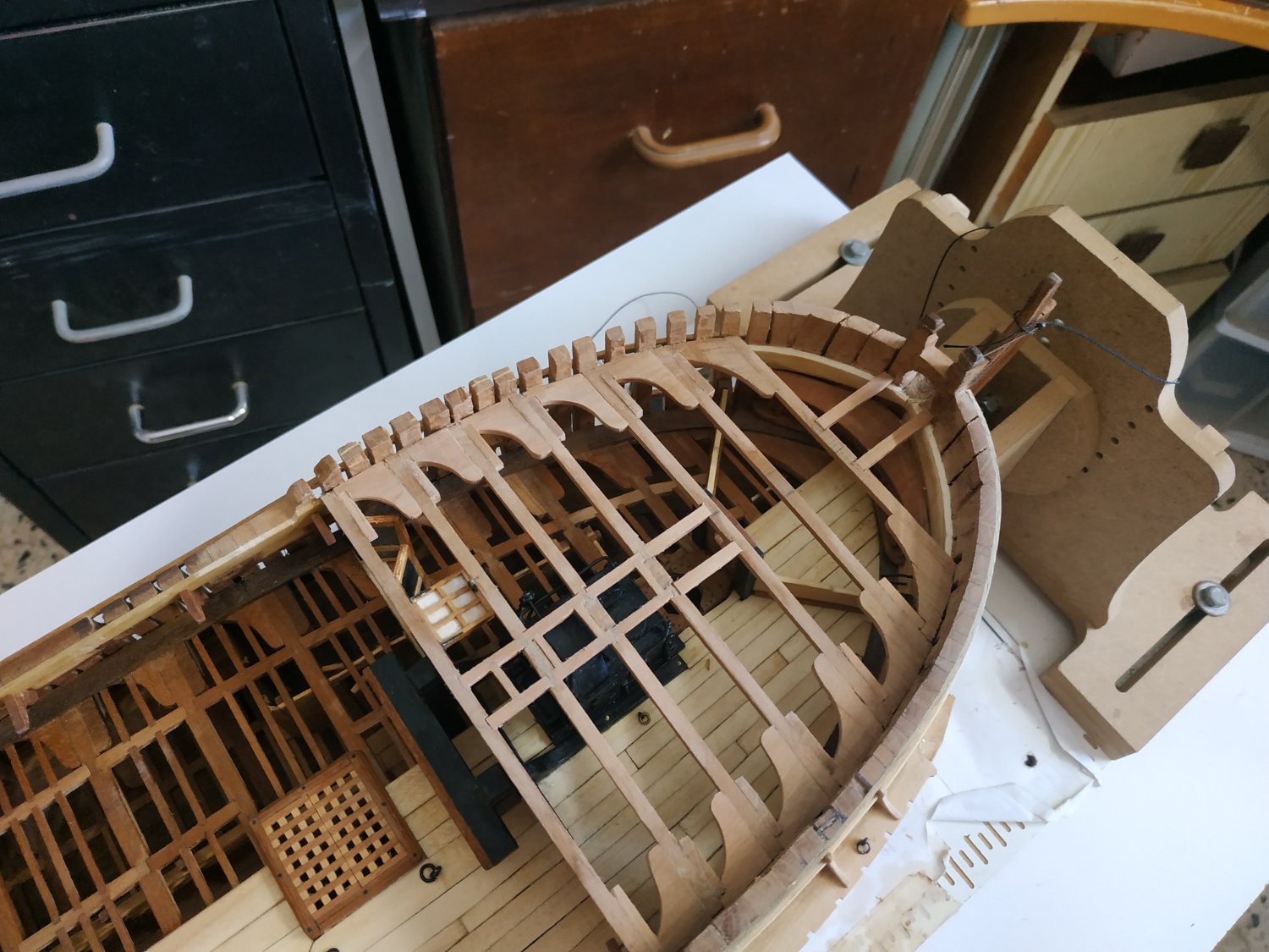
Mizzen Mast Partner Only 1.06mm thick, can be made in 1 piece (see 3D rendition) The hole for the mast is 6.89mm, and towards aft end of the piece. The fore and aft sides are scored down so they sit flush with the Beams. The 1st piece broke, so on second attempt, made smaller hole, glued piece in place, and after planking, the piece being reinforced, will enlarge the hole The Quarter Deck Capstan Partner. Similar construction to the upper deck CP-3 pieces (2.65mm thick) rabbeted together. They don’t sit directly on the beams, but onto Bearer pieces. I made these 2mm, but shaped to fit the curve of the beam,so the bottom edge of the CP sits at deck level. Thus their upper surface is horizontal, onto which the CP sits.( I also put them on the carlings : I didn’t really understand the adapted Carling instruction until after I finished-it comes to the same anyway) The aft bearer is the width of the beam (4.24mm) but the fore bearer (on beam #4) is only 1.59mm wide. The hole is centered above the Capstan Barrel previously fitted. It is lined by an iron hoop, 0.4mm (thickness of my black paper), thus I made the hole 9mm diam. The Partner must sit horizontal to enable the Capstan to turn on a vertical axis. The lower surface is milled and sanded to a wedge-shape (looking from side), the aft edge reduced to about 2mm. ( Holes are also prepared for the ladder stanchions. Why? The ladderway coamings are similar fore and aft. Ok for fore, why not aft. Also looks funny to my eye.)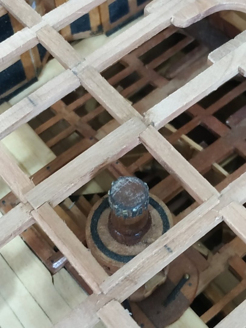

-
Swan-Class Sloop by Stuglo - FINISHED - 1:48
stuglo replied to stuglo's topic in - Build logs for subjects built 1751 - 1800
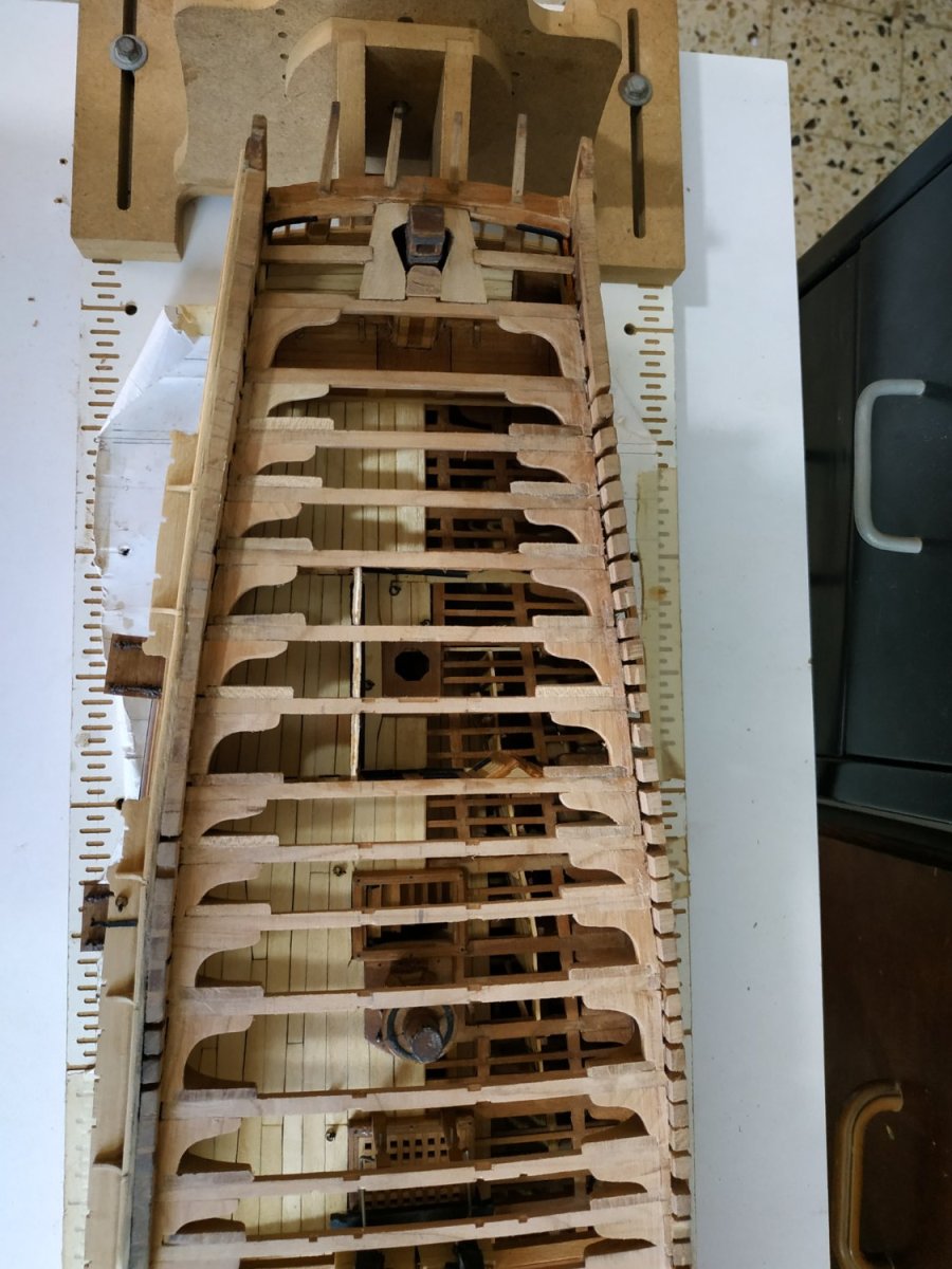
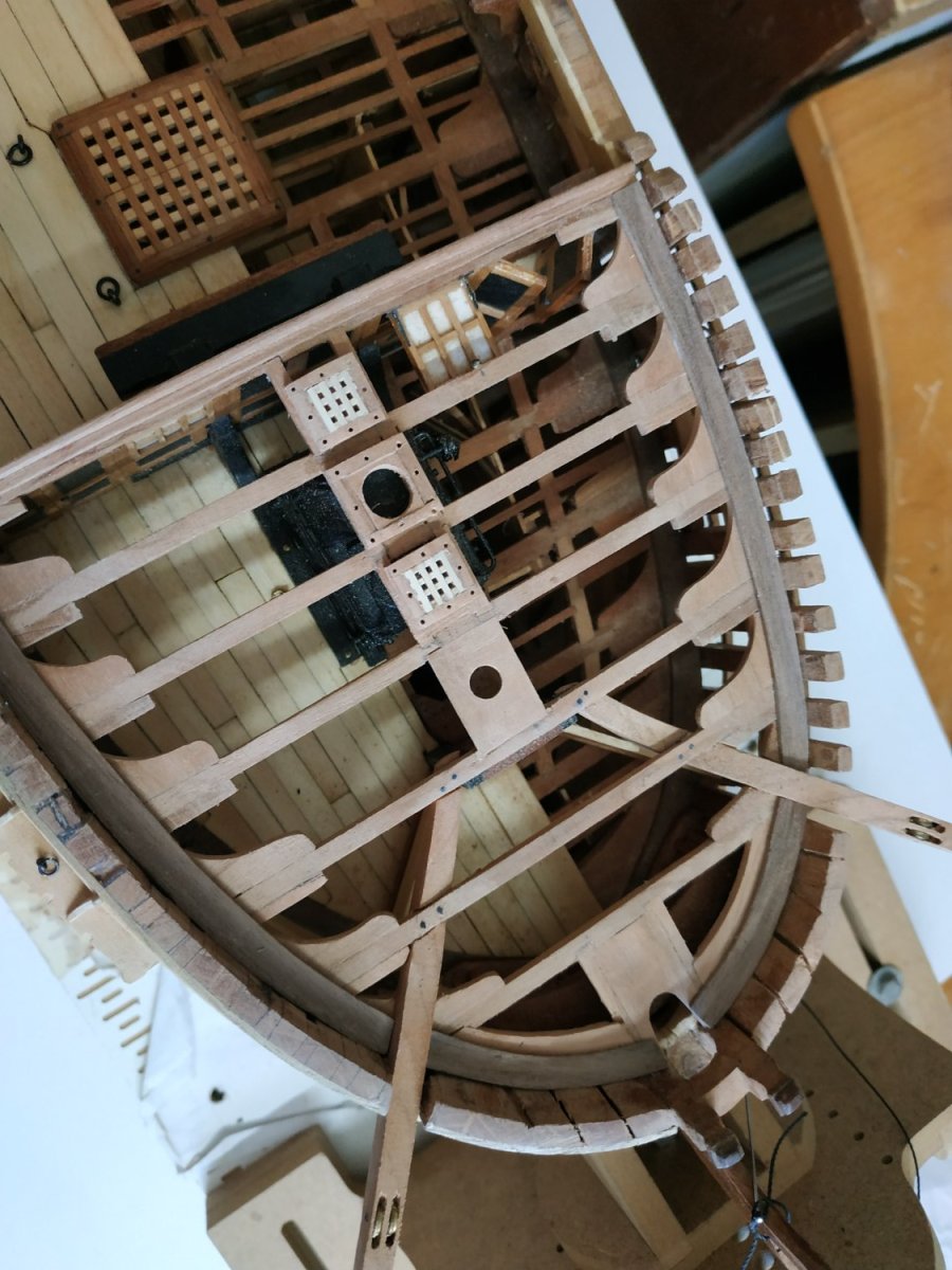
The Quarter Deck Carlings. These are 2.65mm deep and varying widths. As before, mortised onto the Beams. Foreward, they form the base for a pair of scuttles. They are 2.6mm wide. The Ladderway carlings are 4.5mm wide The carlings for the Capstan Partner are 4mm wide.They are parallel. Between Beams #5 and #8. The carlings are also 4mm , but the gap narrows from 24.5 to 22.5mm.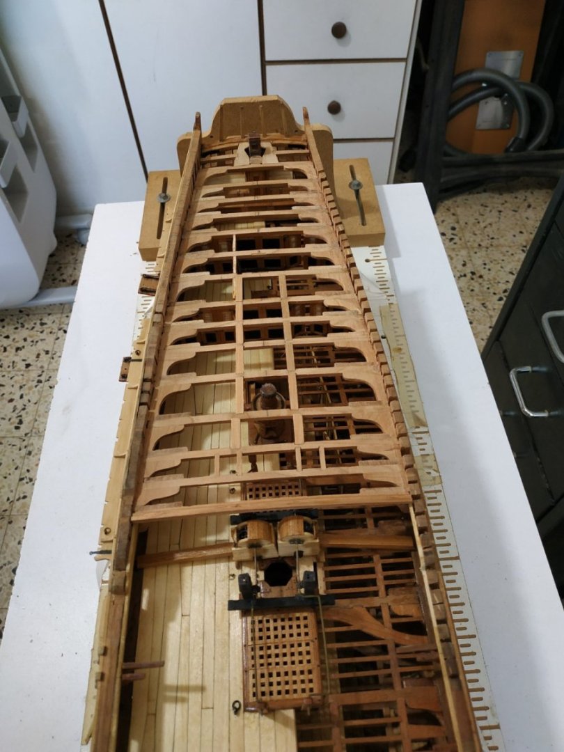
-
Do-It-Yourself Thicknesser
stuglo replied to stuglo's topic in Modeling tools and Workshop Equipment
Thank you. The control switch has built in speed (?amp) regulator. The corrugated cardboard is something I hadn't thought of. Was going to use perspex, but your idea will be tried first. -
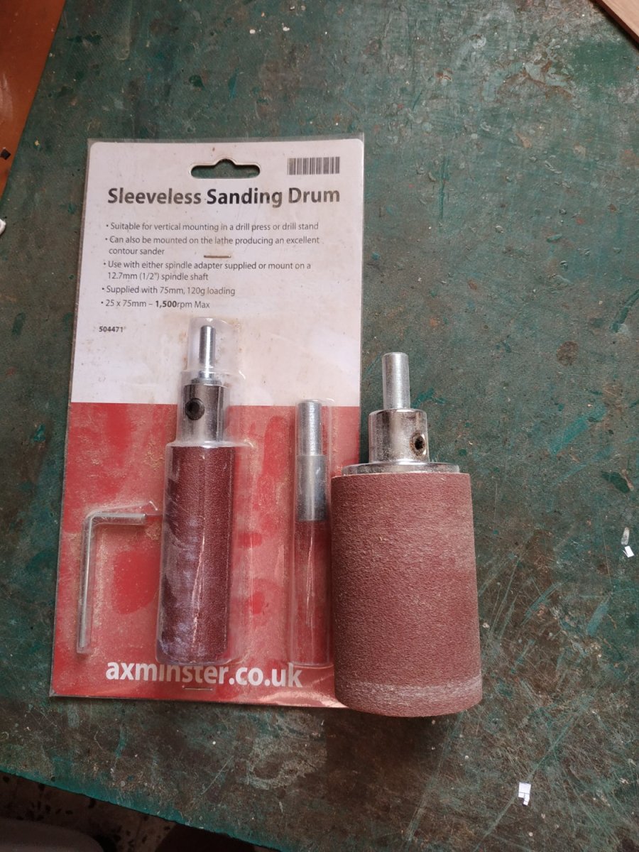
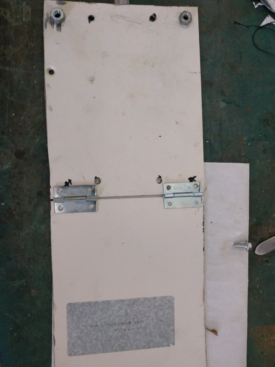
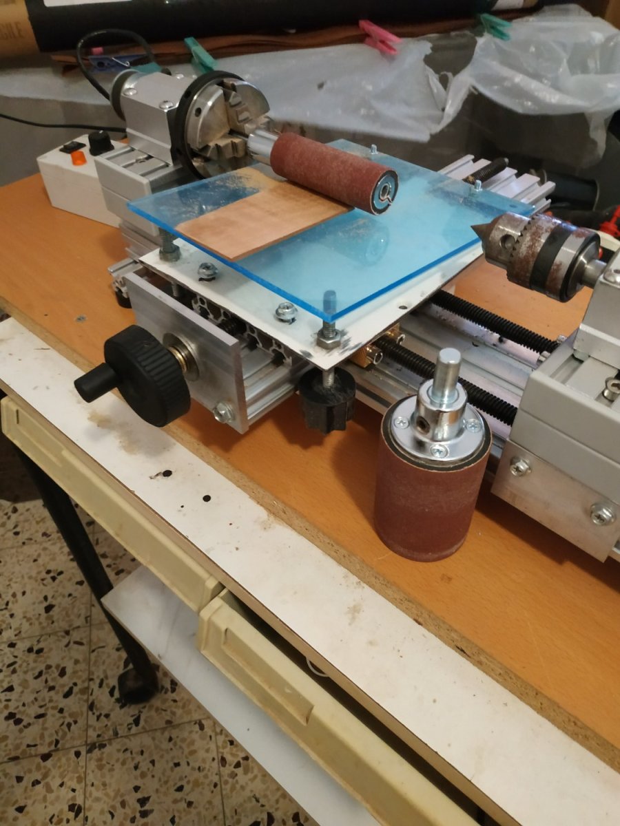
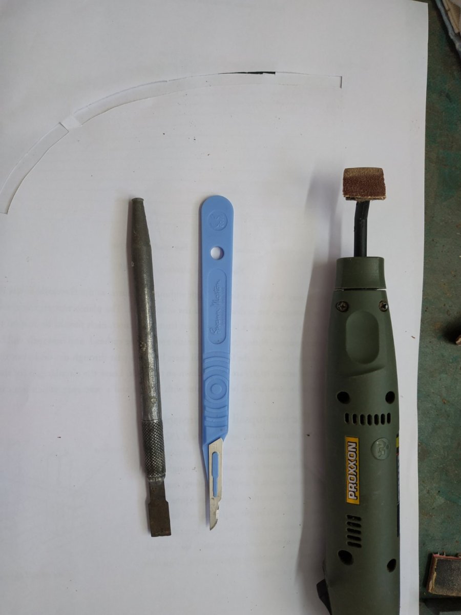
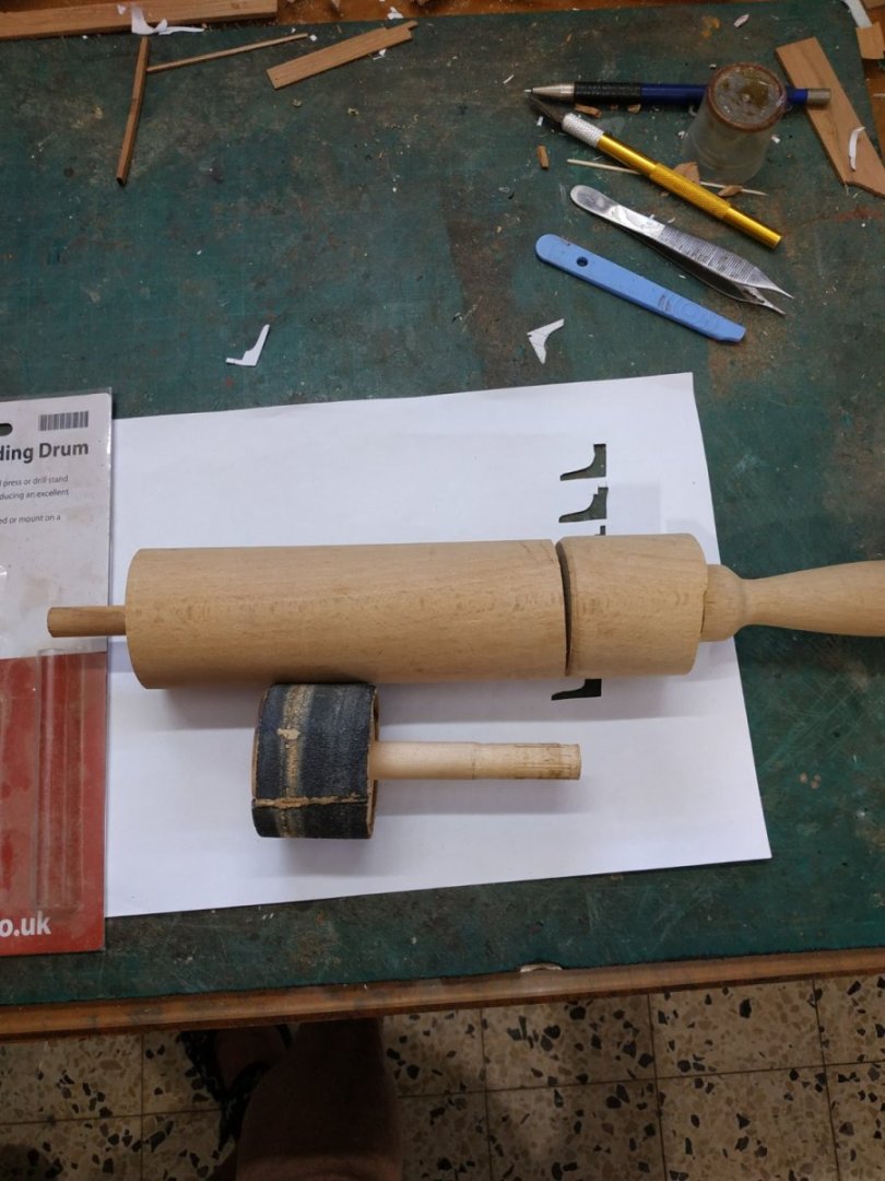
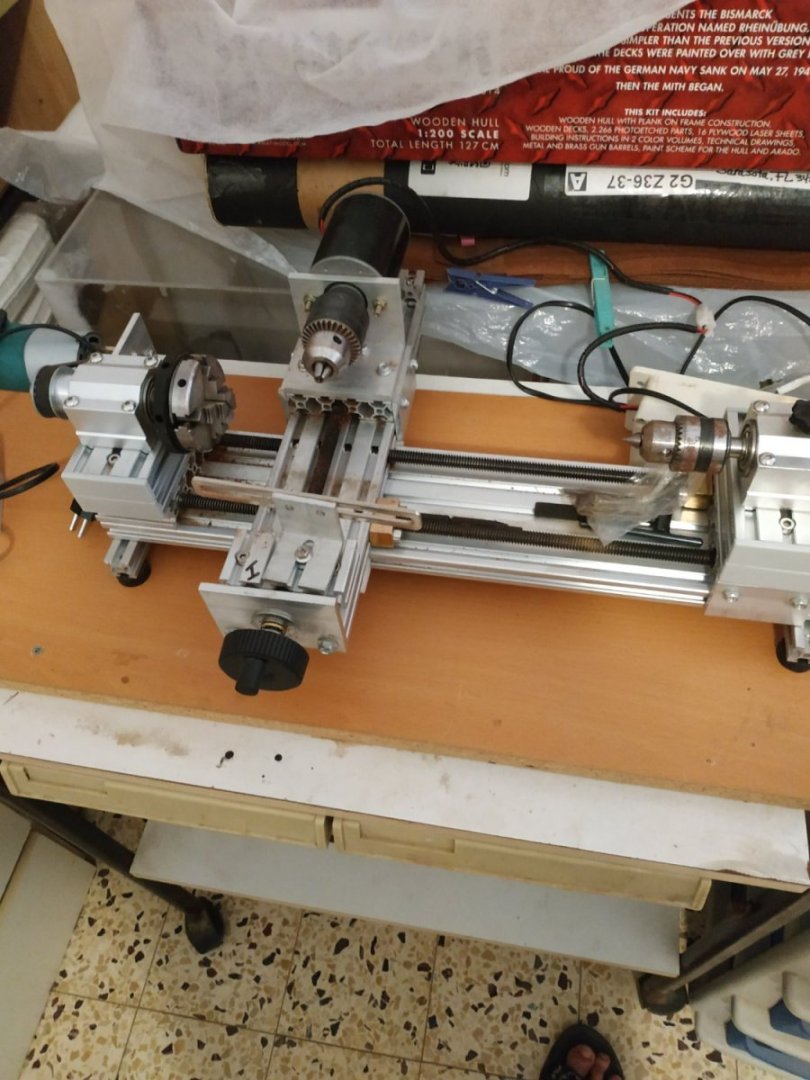
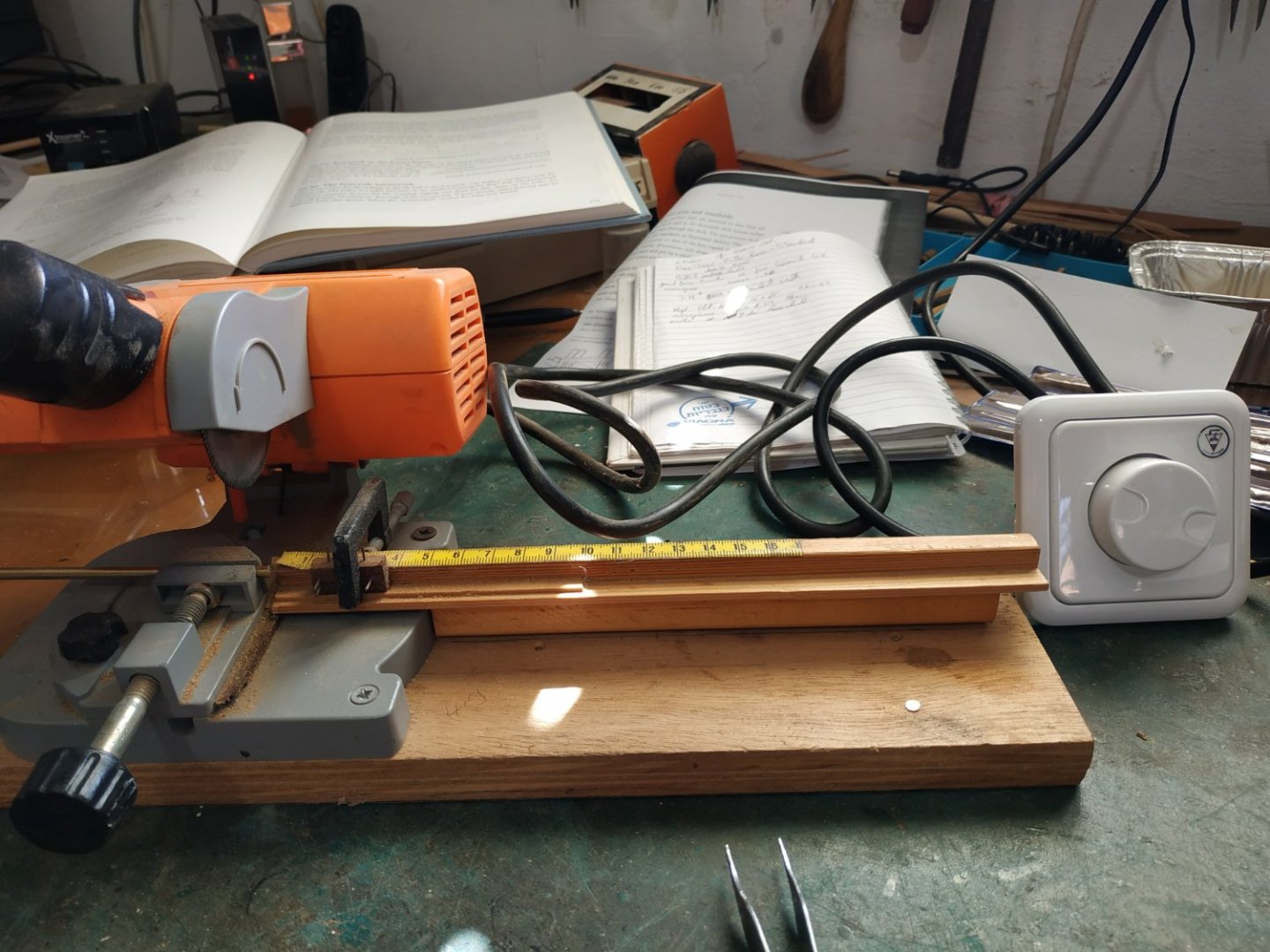
I have a Proxxon thicknesser which is used almost daily. It is good but has 3 major drawbacks: Minimum thickness is only 1.3mm and it chews up short or irregular pieces. (Double-sided tape doesn't work for me). Also it can’t “match” an outer curve - very useful when making beams. I’ve gazed enviously on the Bryne’s offering and recently someone offered (used) something similar. The asking price was very fair, but shipping and tax multiplied cost fourfold or more. I decided to adapt some previous ideas and underused equipment. I remembered a sanding drum I’d made from an old rolling pin, and some sleeveless sanding drums that I’d bought for more accurate work. I had bought a sort of lathe system, with 2 motors and chucks and a 3rd non motorised chuck. The basic plan was to use this as a base, attach a hinged platform adjusted by a screw system. I started with some metal plates 1.75mm thick, which I cut to size and attached the hinges with epoxy-which didn’t hold. I changed to 4mm perspex, breaking a couple of corners when drilling holes for the small nuts and bolts that I used to attach the hinges. So I ended with an upper perspex and lower metal plates. The (metal) elevating screws were set into some handles which were cut off some plastic screws. I know it looks like Heath Robinson on LSD, but it works ! (I thank my wife for donating the rolling pin)


-
Swan-Class Sloop by Stuglo - FINISHED - 1:48
stuglo replied to stuglo's topic in - Build logs for subjects built 1751 - 1800
Its fun to make. I used the mill and sanding boards. Aligning the cut-outs for the pintles and those already made on the sternpost was fiddly. I had to enlarge the helm port to allow the correct angle and gap between rudder and sternpost. Mine probably should have bin slightly wider. I'm still dissatisfied by the straps. Will rethink near end of build. (ps seriously, the next time I build a Swan, it will be planked and rigged, leaving-out the "innards") -
Swan-Class Sloop by Stuglo - FINISHED - 1:48
stuglo replied to stuglo's topic in - Build logs for subjects built 1751 - 1800
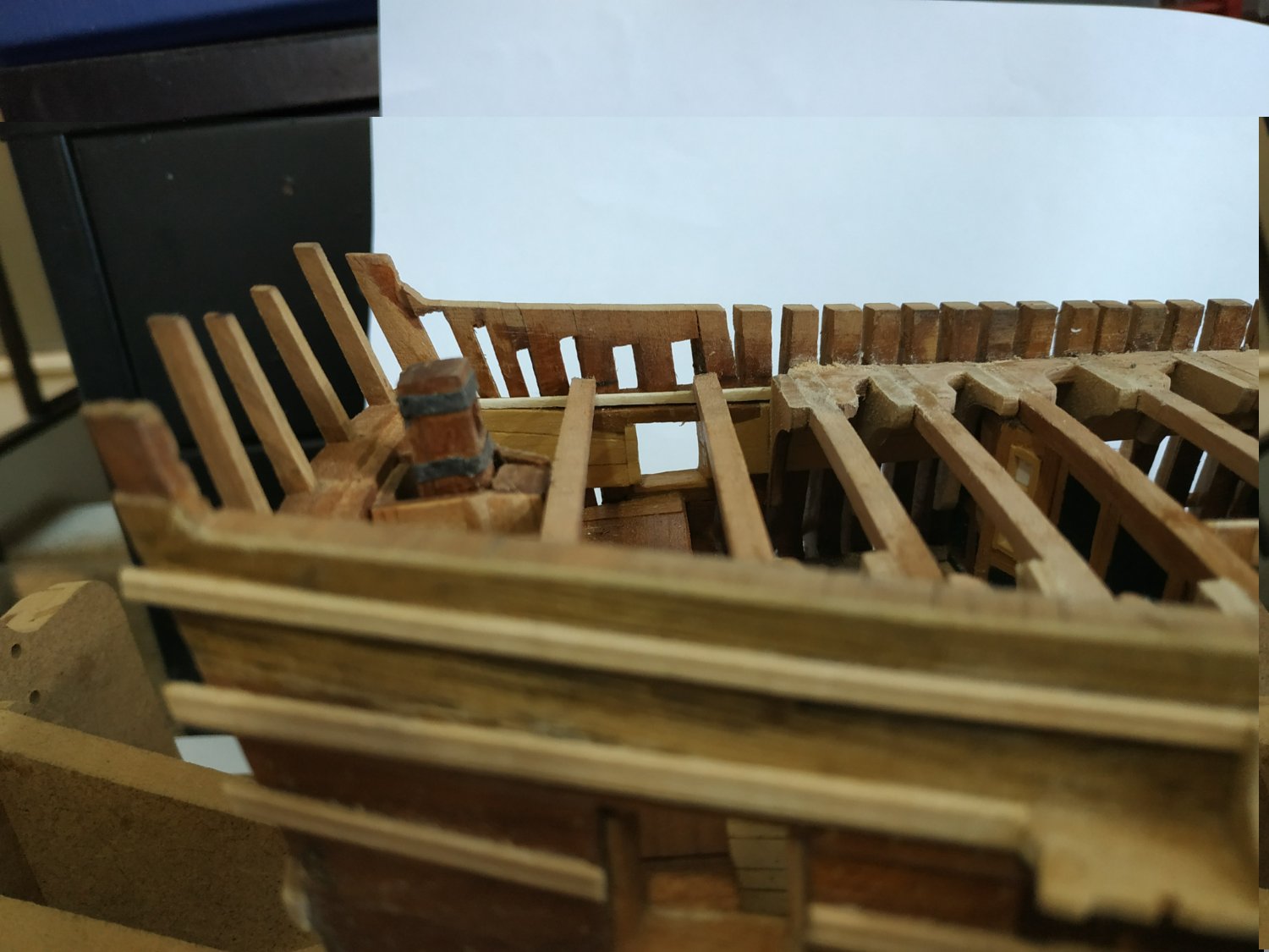
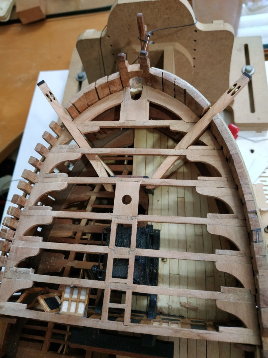
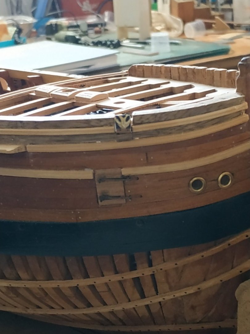
Rudderhead Framing. Three pieces of 2.65mm, 2 sides and 1 joining piece aft of the Rudder. Rabbeted joints, they sit flush with beam#15 and the Transom, aft. This latter also needs scoring. The opening is fan-shaped to allow rotation of the Rudder. The height of the Rudderhead Trunk needs adjusting to allow the frame to sit on it. TFFM suggests an half-beam from either side of the frame to the deck clamp. This requires scoring the Frame. An Iron Knee is fixed between the Transom and inner hull planking. I made this with thick, black card.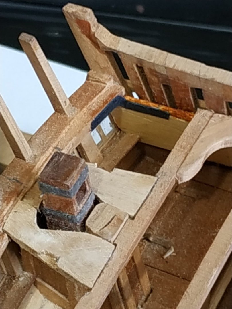
-
Swan-Class Sloop by Stuglo - FINISHED - 1:48
stuglo replied to stuglo's topic in - Build logs for subjects built 1751 - 1800
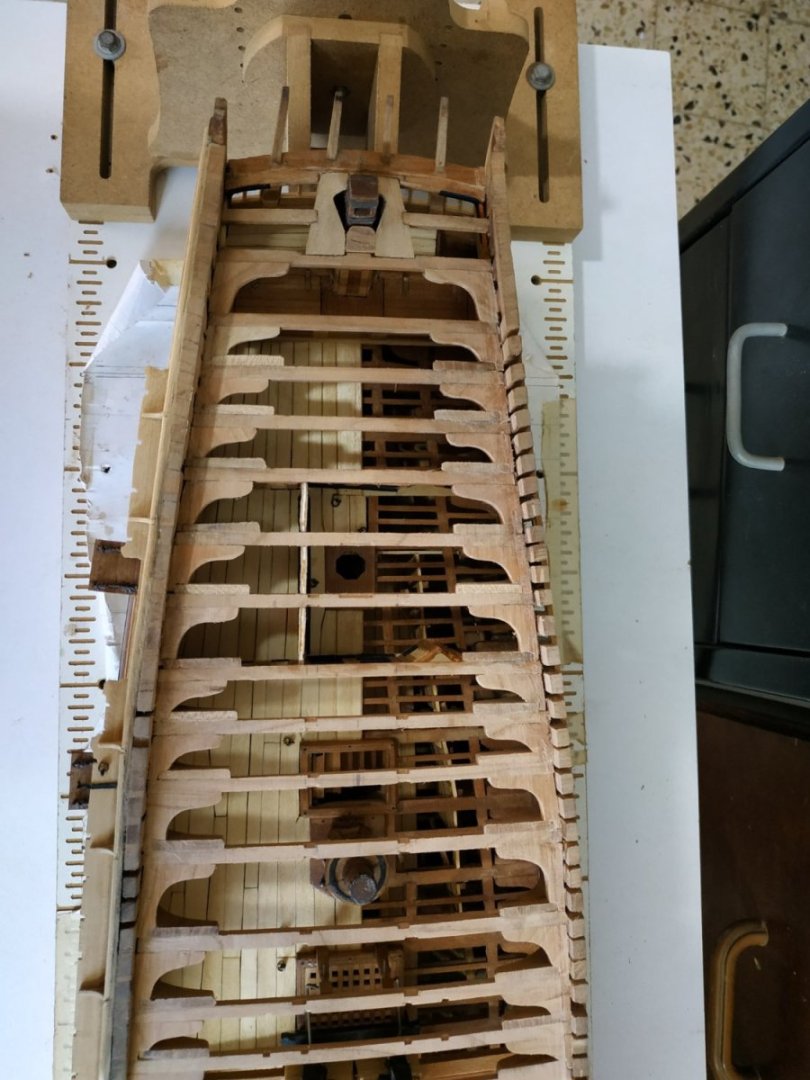
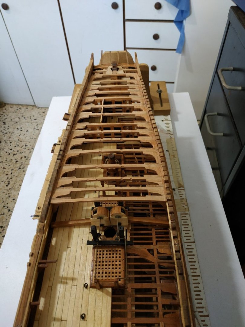
Quarter Deck Beams. These have already been made so as to enable fitting of upper deck bulkheads. The Beams are 2.9mm deep. I posted a question on how to reconcile this depth, without Letting Down if the Lodging knees are only 2.39mm, as these usually sit on the deck clamp. In order that the upper surface is flush with the Beam, this must mean that either the Beam is let down by 0.51mm, the Knee is thickened to match the beam,2.9mm or the knee doesn’t sit on the clamp. I went with the thickened Lodging Knee. The “arms” of the L.K. are 19.1m The Hanging Knee is 2.65mm thick, arm 17.49mm and leg over the spirketting. I REMEMBERED to mill mortises for Carlings before fitting Beams. The Carlings are all 2.65mm deep but varying widths. For the: Scuttle, 2.39mm width Ladder Way 4.5 mm Between Beams #5 to #9 the Carlings are 4.1mm wide. The form a line which tapers, so that the distance between the carlings at Beam #5, are 24.5mm and at #9 =22.5mm. I had some difficulty fitting the Lodging Knees after the Hanging Knee and its aft partner were fitted, because the “tongue” of the L.K. would break off if fitted to closely into the notch of the H.K. In the end, dry fitting the assembly and then gluing the knees before finally fixing the Beam. The fore/aft bulkhead can be fitted after #8 Beam in place. The Mizzen mast partner is fitted between #9and#10, and the beams are scored to 0.53mm for the mortise. Beam #15 scored for the Rudderhead framing mortise and fitting to the angle of the Rudderhead itself. Only when the Beams and Knees were already fixed in place, I noticed that aft of Beam #10, the Beams were not aligned with the Transom on the Port side, the deck didn’t angle upwards sufficiently. Ungluing everything, I saw the cause was the height of the upper port framing and the neighbouring spirketting. To correct this, I added a long wedge of inner planking, from 0 to 2mm at the Transom. The Beams and Knees refixed (some being remade) and this problem solved There is no room for a Hanging Knee at #14 Beam, so it was omitted.
-
Swan-Class Sloop by Stuglo - FINISHED - 1:48
stuglo replied to stuglo's topic in - Build logs for subjects built 1751 - 1800
Thanks -
Swan-Class Sloop by Stuglo - FINISHED - 1:48
stuglo replied to stuglo's topic in - Build logs for subjects built 1751 - 1800
I have these 3D's. They seem to prove my point, they are the same thickness. So the Lodging Knees need thickening to much? TFFM authors and others, please advise. (I'm losing sleep) -
Swan-Class Sloop by Stuglo - FINISHED - 1:48
stuglo replied to stuglo's topic in - Build logs for subjects built 1751 - 1800
HELP WANTED !! Thickness of Beams and Lodging Knees. Both these sit on the deck clamps. How can they sit flush if they are different thicknesses. Lower and possibly upper deck beams are let down. I cheated with the forecastle and made thicker knees. I can't see a different solution for the quarter deck, where the beam is 5.5 in and the knee only 4.5 in. What am I missing? -
Swan-Class Sloop by Stuglo - FINISHED - 1:48
stuglo replied to stuglo's topic in - Build logs for subjects built 1751 - 1800
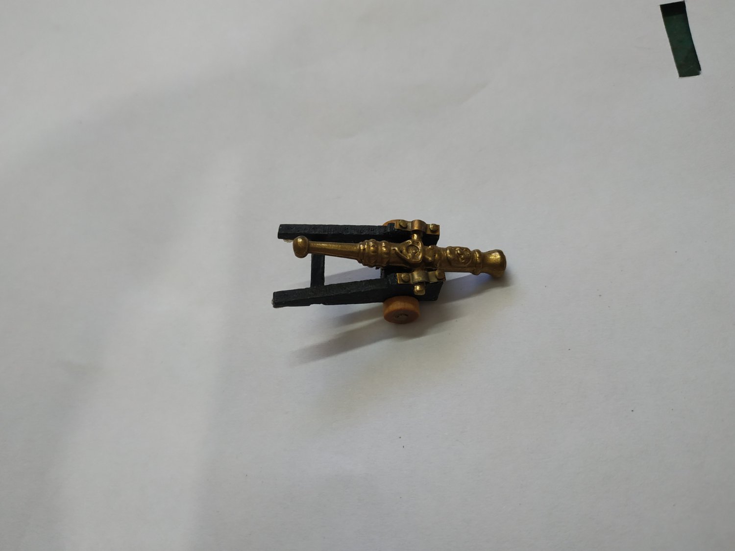
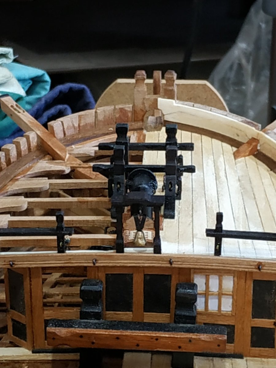
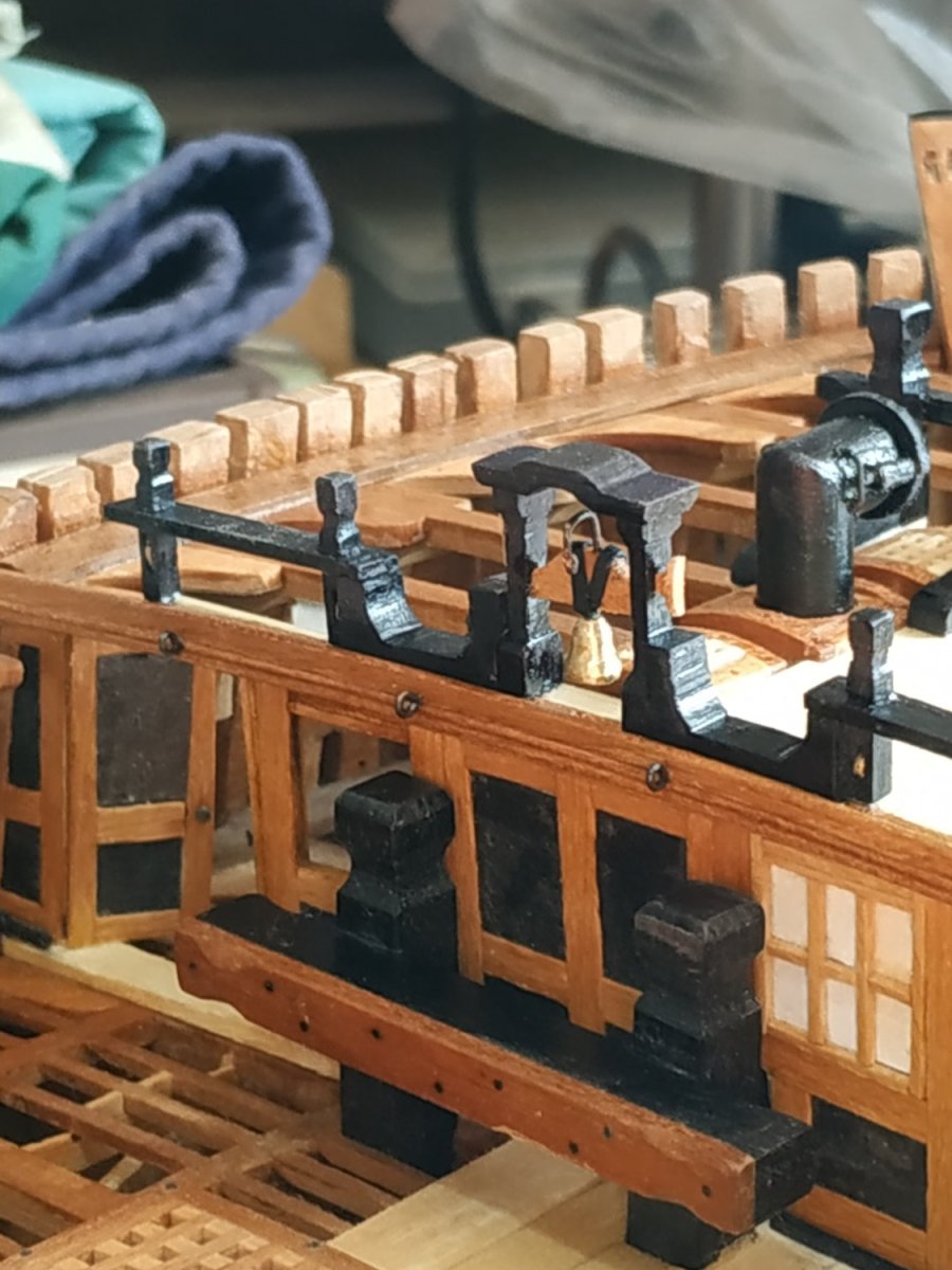
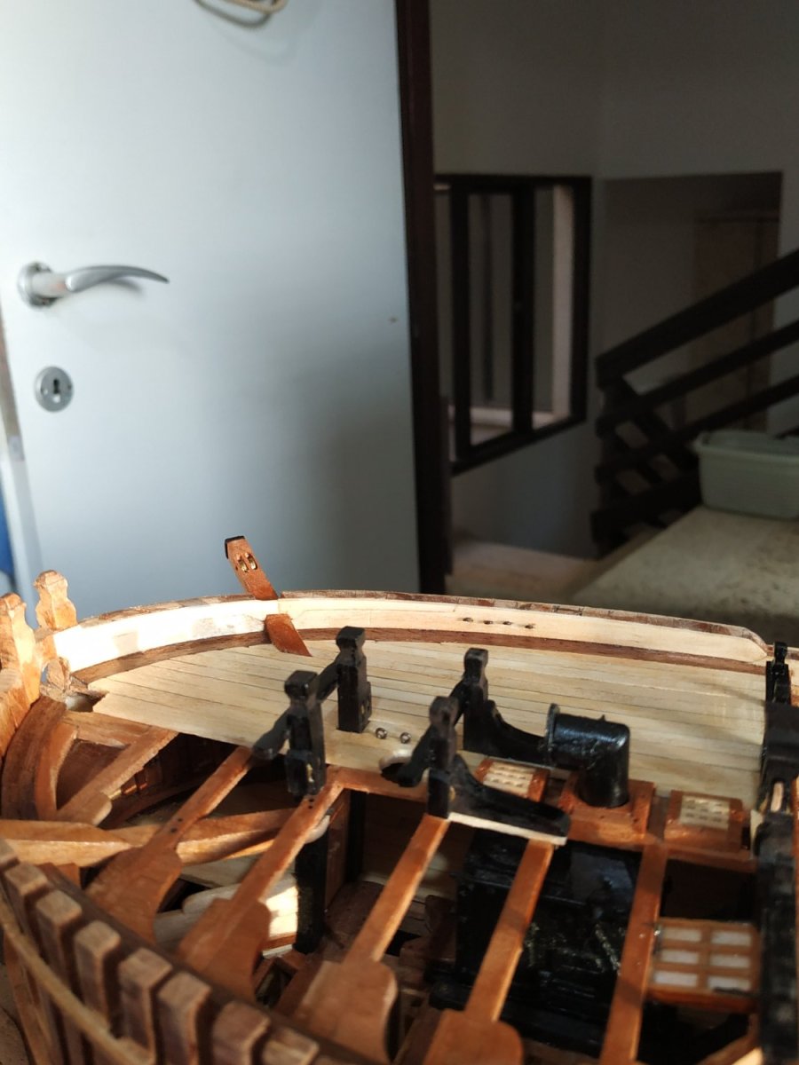
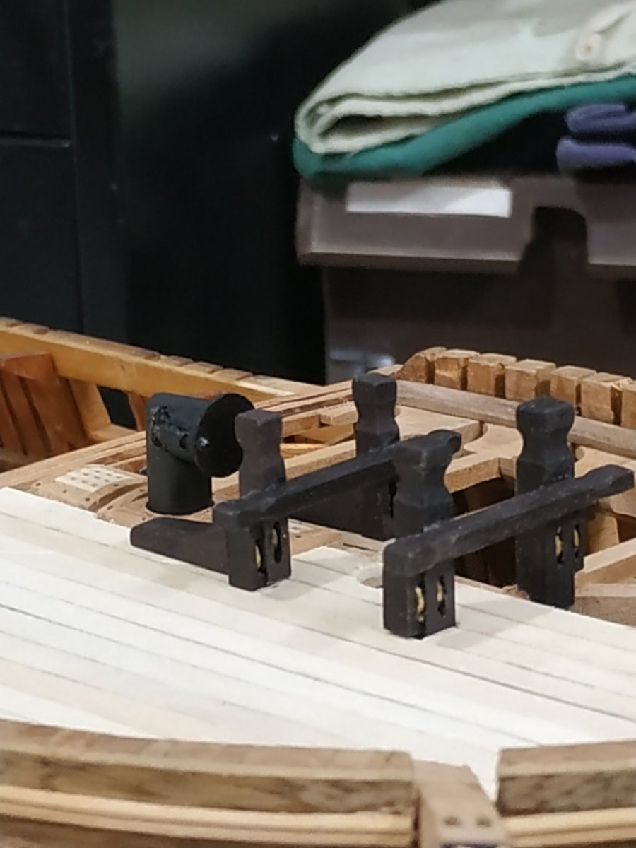
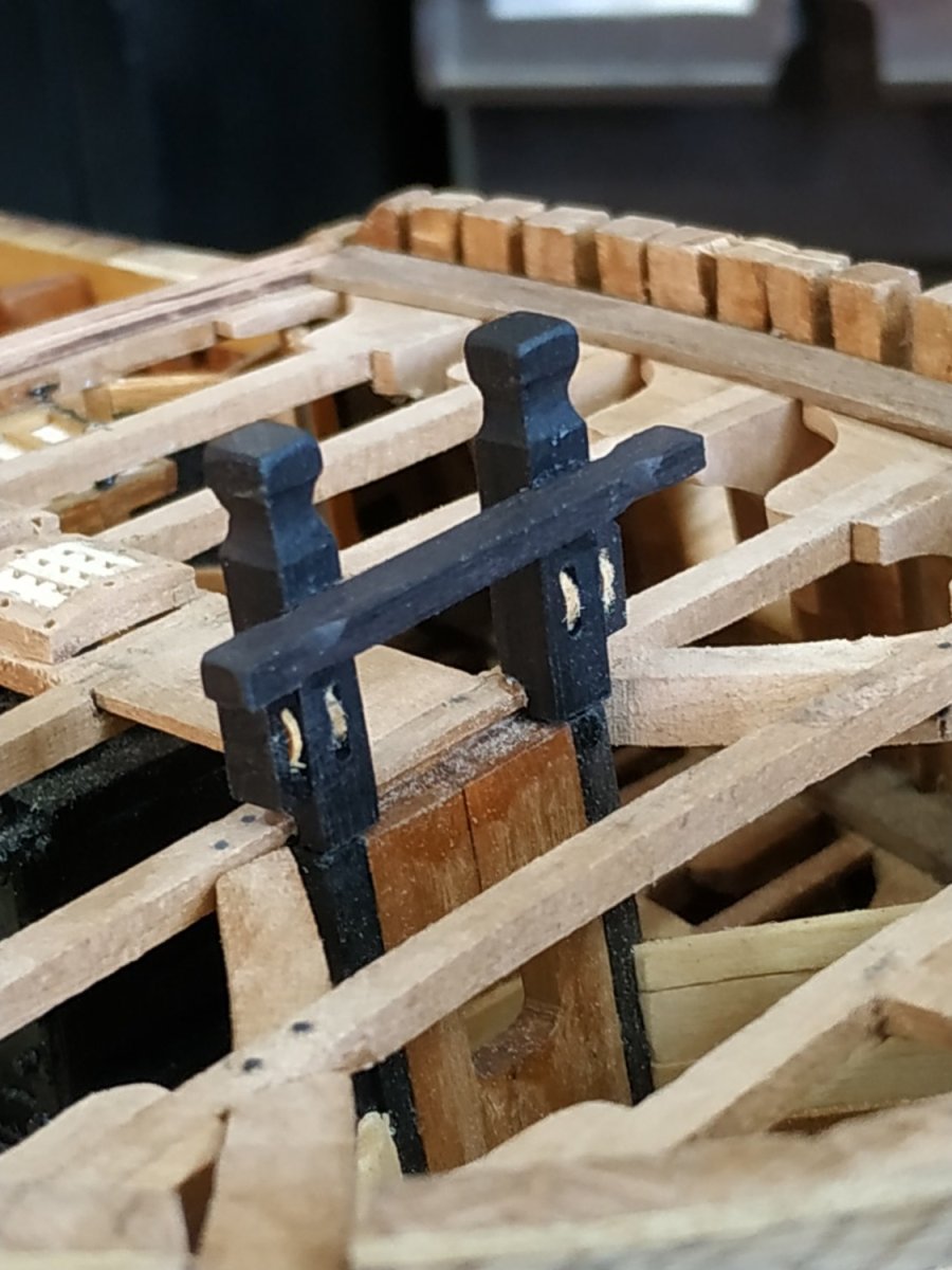
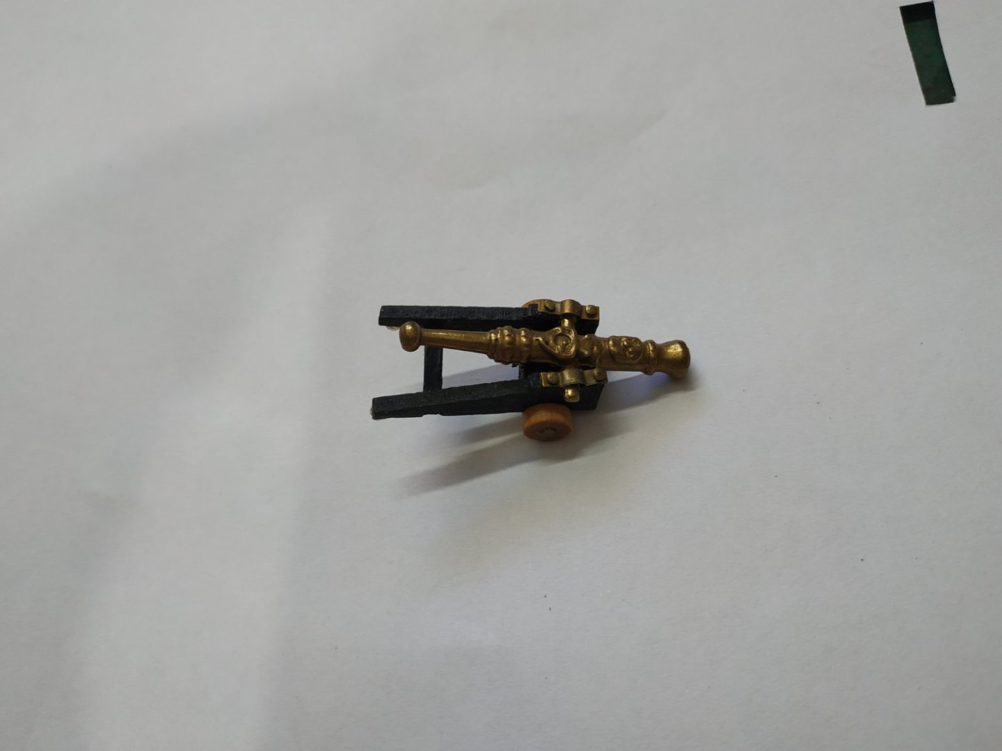
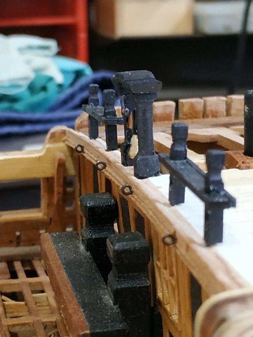
The Forecastle Breastwork. This is the Railing at the aft end of the Forecastle, either side of a central Belfry. Stanchions: A pair either side, with sheaves. 2.25mm sq., 12.75mm tall. Shaped similarly to the tops of the Bitt Pins The sheave, 0.46x2.12mm in a slit beneath the Rail. Pegged (part brass pin) onto the Breast Beam, ensuring they are vertical. Rails: 4.24X1.33mm enclosing the Stanchions. Again, as suggested by TFFM, made with notches and a finishing strip.An accurate square “hole” is difficult. Cutting this notch with a knife,chisel or saw, caused breakages to the thin blank. The milling bit did a better job The practicum calls for creating a molding around the edges. I found this impossible. Rather I chamfered these edges. The Rails are fixed parallel to the deck. The Belfry . Consist of 2 Stanchions, a Canopy (roof) and Headstock,from which suspends a bell. The Stanchions 4.77x2.25x16mm. With thickening at top and base. The Canopy. I decided to make this as a shaped single piece, rather than 3 pieces. Omega shaped, also edged with a stepped molding, which I again failed to create and so chamfered. Headstock. 1.6mm wide, yoke shaped. Placed halfway up the Stanchions. The “V”metal straps, using thick black paper. At its base is the brass Bell. Max width and height about 4.5mm and bell-shaped. My efforts at brass turning are so far pathetic. Looking for something to adapt, I saw the end of a cannon left over from a kit. Cutting this and shaping with a sanding wand, seems ok. Above the Headstock is a bell crank - a ready made eyebolt bent to shape. The above was assembled and fitted, and only now I made the Spar Rack. I think this was easier, rather than before the Belfry. Spar Rack. Filling the gap between the inner Stanchions and the Belfry. Width again 4.24mm, “U” shaped, the outer limb fits under the Rail, the other is this height + 1.33mm (thickness of the Rail). The outermost edge shaped to fit the neighbouring edge of Belfry Upright. Again shaped by my Proxxon mill - a really useful machine.


-
Swan-Class Sloop by Stuglo - FINISHED - 1:48
stuglo replied to stuglo's topic in - Build logs for subjects built 1751 - 1800
Forecastle Bulwark Planking Referring back to ch.4 - the inner planking expansion.(planks 26,27,28) #26, short plank aft of Breast Beam #27, the lower strake interrupted by the Catshead, continues to Bowsprit #28, the upper strake widens over the Catshead, and encloses the upper part of the Bowsprit. I had difficulty making this in one piece. Cutting to size and accurately placing the expansion over the Catshead didn’t seem to work even with the plank heated to take the bend. After 4 or 5 attempts, I took the cowards way out, and divided the plank above the Catshead. A series of 4 eye bolts are countersunk on the #27. These are referred to as the Ironwork. Countersinking, as suggested by TFFM, using a narrow flat screwdriver. The (shortened) eyebolt is fitted after drilling the usual hole in the center of the depression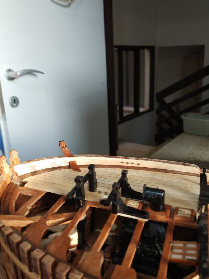
-
Swan-Class Sloop by Stuglo - FINISHED - 1:48
stuglo replied to stuglo's topic in - Build logs for subjects built 1751 - 1800
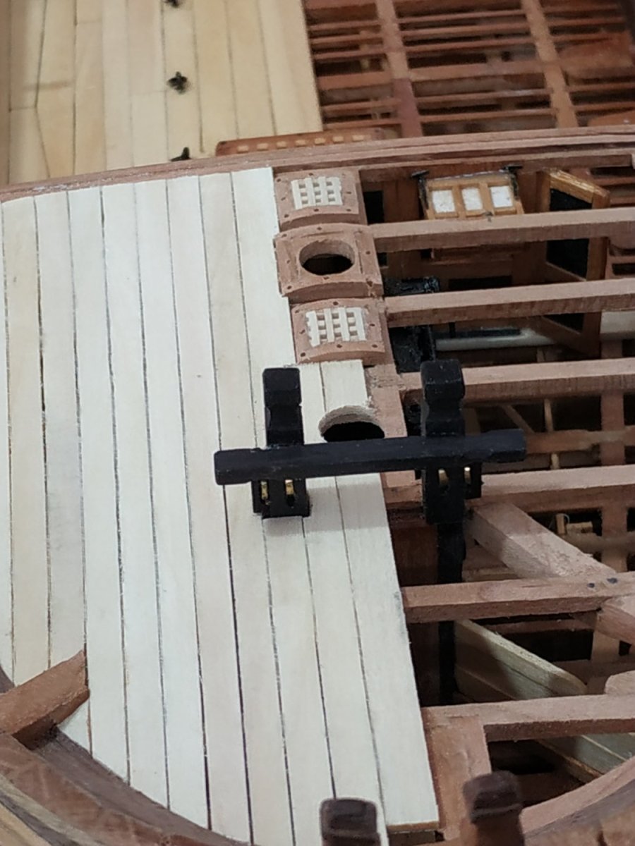
Fore Jeer Bitt Pins and Standard. Unlike others, these are bolted down over the deck planking. In form, similar to Fore Topsail Bitt. The Pins are 3.71mm sq. and the standards , if I understand TFFM correctly, are made of one piece with them. I anticipated difficulties in making the various moticses, sheave slits shaped tops etc, so I made them separately, did the necessary milling and drilling, then stuck them together. The crosspiece is again 3.45x2.39x36mm, the lower surface 9mm above the planking. The sleave slit extends through the Standard, but this can now be made in the drill bench press. A set of brass disks are fitted as sheaves. The Pins sit on beam#4 and extend aft so the Standard near the Cowl Coaming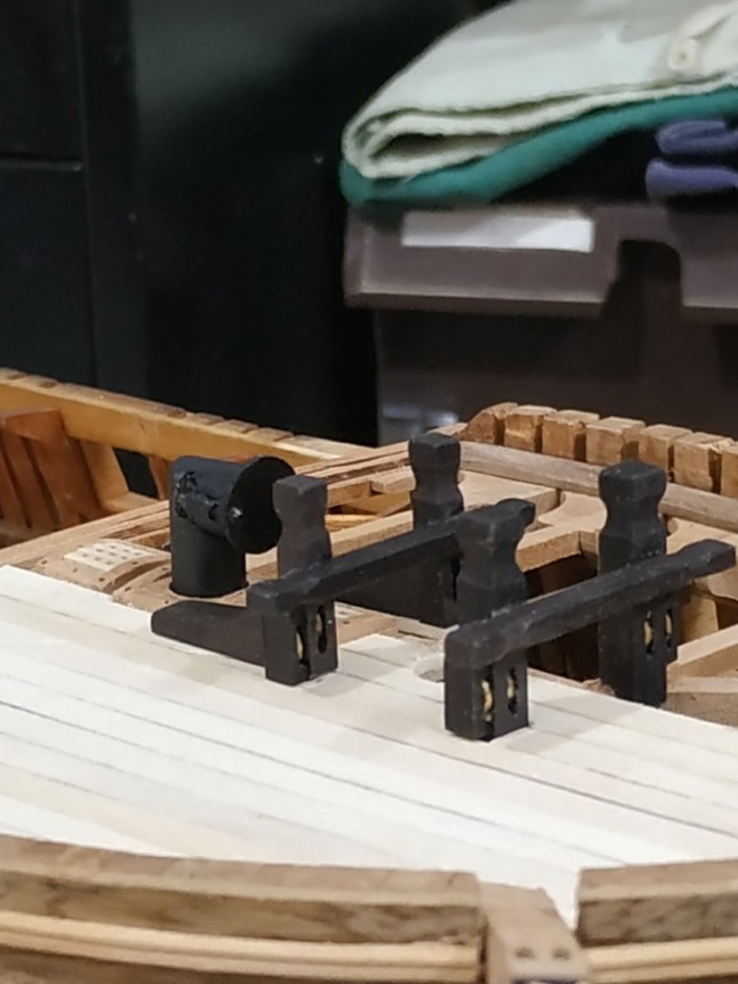
-
Swan-Class Sloop by Stuglo - FINISHED - 1:48
stuglo replied to stuglo's topic in - Build logs for subjects built 1751 - 1800
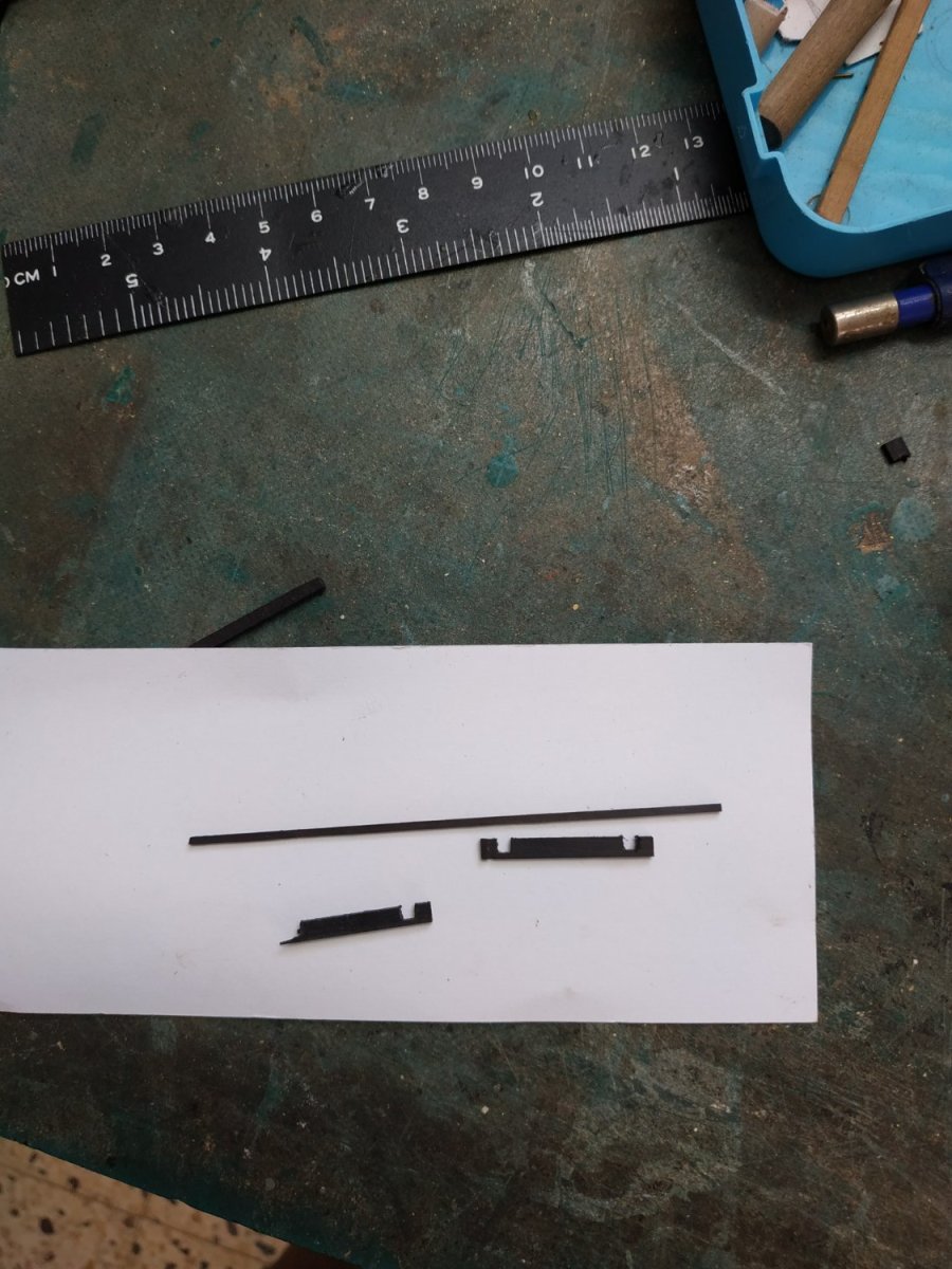
Sheaves and Brass The wooden sheaves look terrible. I ordered some brass rods recently but have only a simple lathe (built from 6in1 classic Unimat) No suitable cutting tools, although I adapted some small screwdrivers for woodwork. I have an old mitre cutoff saw. As scratch building doesn’t lend itself to mass reproduction, I’vr not used it for a couple of years. No special blade, I can cut through the brass. The brass gets pretty hot and sometimes the saw sticks. I decided to slow it down and connected a light “dimmer” switch. It is much improve and gives me down to 0.5 mm slices (The central holding screw is rusted in -WD40 doesn't work. Please advise as I would like to change the blade to carbide-tipped or a cutting disk) Also, not able to make the required grooves. I welcome suggestions to adapt by toy lathe and the tools I will need to slice groove shape etc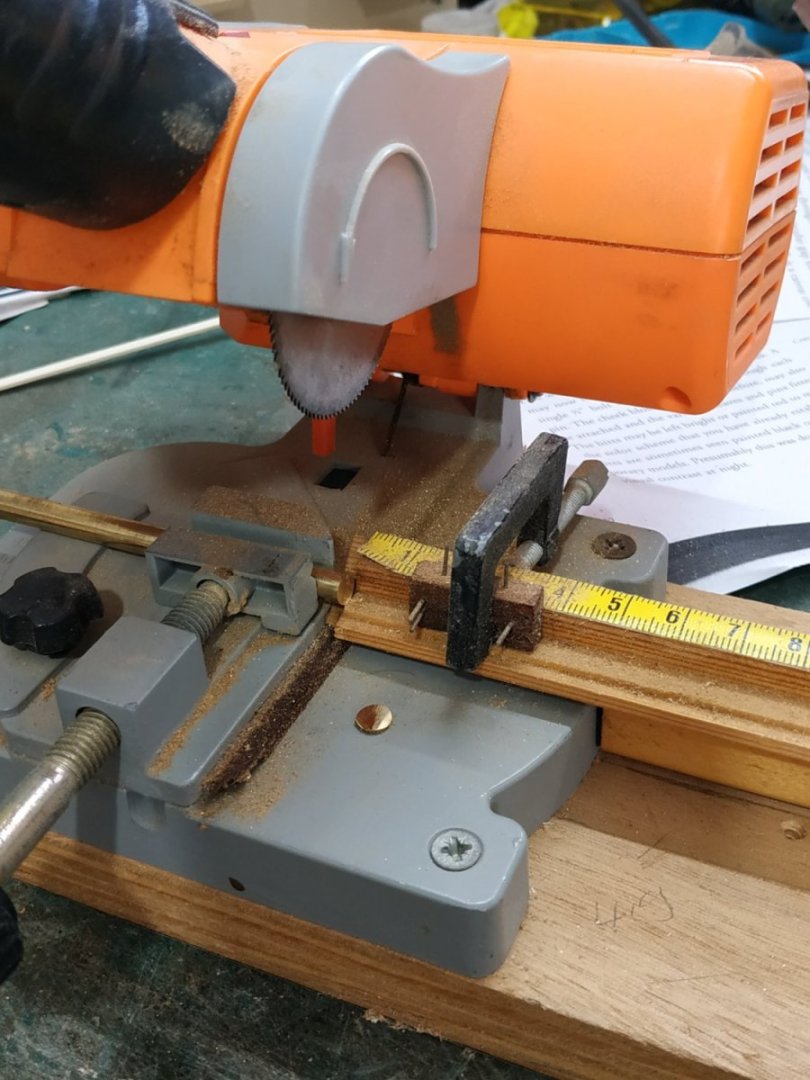
-
Swan-Class Sloop by Stuglo - FINISHED - 1:48
stuglo replied to stuglo's topic in - Build logs for subjects built 1751 - 1800
Planking the Forecastle. The planks are 1.33mm thick. The Centreplank is of similar thickness, but a bit wider. As all the planks are less than 22ft no butt joints are necessary. The planks taper, approx 4mm foreward, to 4.77mm aft. This gives a curved effect. The 7th plank passes over the Cathead, whose upper surface is notched to allow this plank to lie flush with its neighbours. The tips of the next 3 planks are “barbed” otherwise the end width would be too narrow. I’ve penciled the edges and left gaps between the planks to represent caulking,but I do not plan to nail as the effect, to me at least, often seems exaggerated. ( I understand that they probably couldn’t be seen-hypocrite that I am, I like them on the hull and elsewhere,as decorative features.)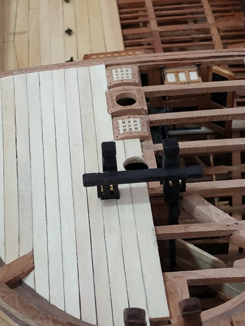
-
Swan-Class Sloop by Stuglo - FINISHED - 1:48
stuglo replied to stuglo's topic in - Build logs for subjects built 1751 - 1800
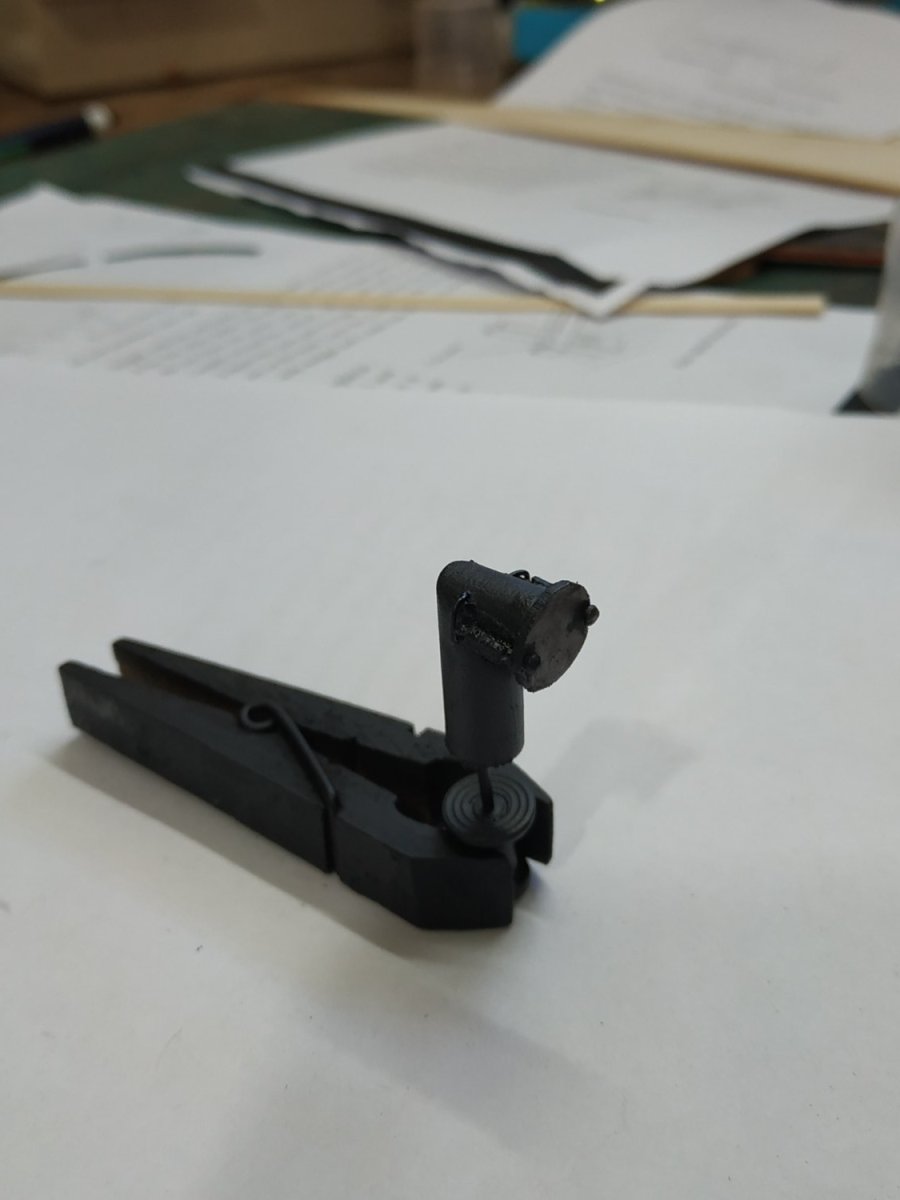
The Cowel Sits on the upper chimney of the Stove, and passes through the foredeck via a hole in a metal plate. The Cowel Base. I used a wooden dowel, cut at an angle slightly more than 45deg, instead of fabricating from metal. The opening faces forward, but the air intake is regulated by a Baffle. This is a thin disk, slightly larger than the aperture, which can be moved fore/aft. I made this also from a thin slice of dowel. The slides are made from cutdown dressmaker’s pins, the tube from insulation for thin electric wire, and the handle from copper wire. The ensemble painted black
-
Swan-Class Sloop by Stuglo - FINISHED - 1:48
stuglo replied to stuglo's topic in - Build logs for subjects built 1751 - 1800
Return to the Bowsprit Step: I decided to make the uprights separately- the lower part already made and fixed before the upper deck. These Uprights,are 4.24mm square and height 22mm above the Beam (plans) They are scored onto the beam so to sit on the top of the Step frame. The top of the Pins are shaped using a rounded milling piece to form a slight concavity, and the top corners are chamfered. These uprights are also scored to depth 0.66m to accept a crosspiece-at 13mm above the deck The Crosspiece 3.45x2.39mm with length 37mm. Chamfered at the edges and slightly scalloped near the ends. Slits for the Sheaves Below the crosspiece, a slit is made for a 3.7x1mm sheave This will be the same be at the level of a sheave 3.71x0.53mm, within a Cheek attached to the side of the Upright. The Cheek sits on the deck planks, is 1.6mm wide and 8mm high. Rather than make these separately I decided to take a strip, form the pattern along its length, and then cut to the required width (slightly narrower than the uprights). It is mortised to a depth of 0.6 mm x 4.2mm to take the sheave.(milled) The top forms a molding (I made with a 1mm milling bit “stepped” across and down. BRILLIANT !!! except that I made the mortise on the wrong side. The molding should slope outwards !!! Start again.(But the method was good). I made the sheaves from wood and temporarily glued the assembly in place, I must learn to cut slices from copper rods I recently bought.

- 475 replies
-
- 11
-

-
Swan-Class Sloop by Stuglo - FINISHED - 1:48
stuglo replied to stuglo's topic in - Build logs for subjects built 1751 - 1800
Forecastle Waterway Size - max thickness 2.12 with the”:flattened “ section 1.33mm to be flush with the planks. I tried a different method for shaping- scalpels and the Proxxon sanding wand. This seemed more efficient in time and result. (not obvious yet, but a contrasting wood used- walnut I think, because it gives me the sneezes!!)

- 475 replies
-
- 10
-
-
Swan-Class Sloop by Stuglo - FINISHED - 1:48
stuglo replied to stuglo's topic in - Build logs for subjects built 1751 - 1800
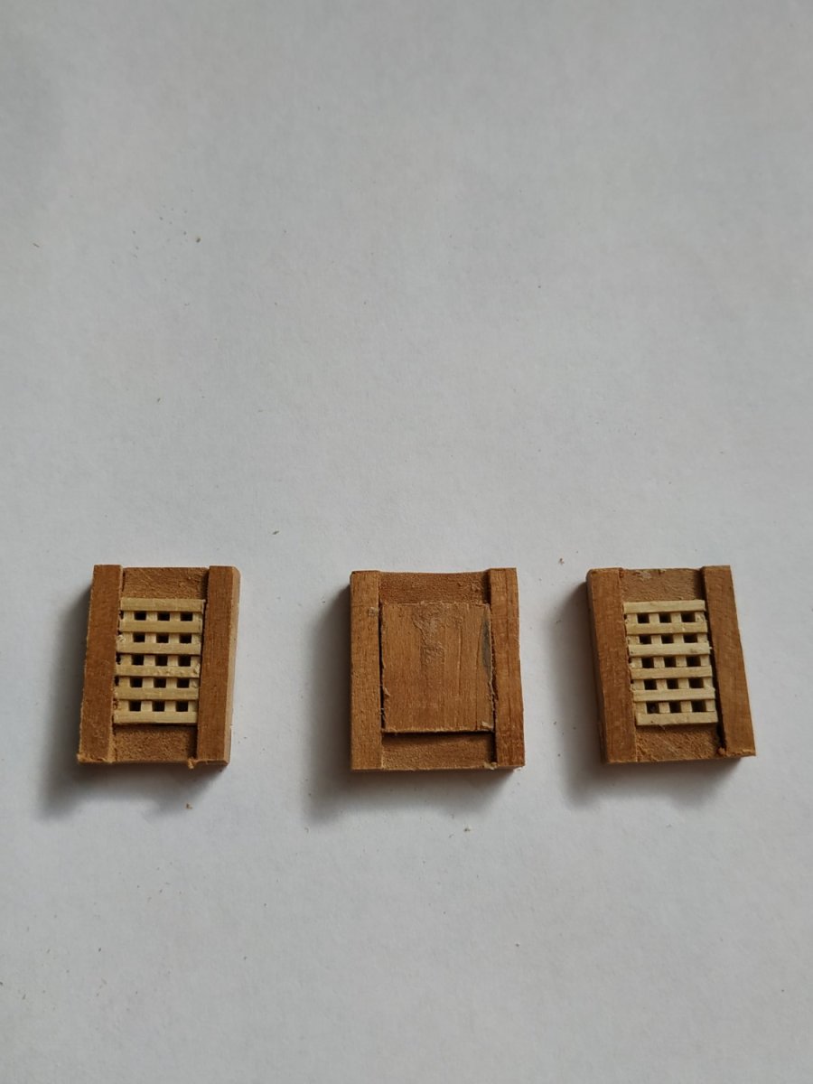
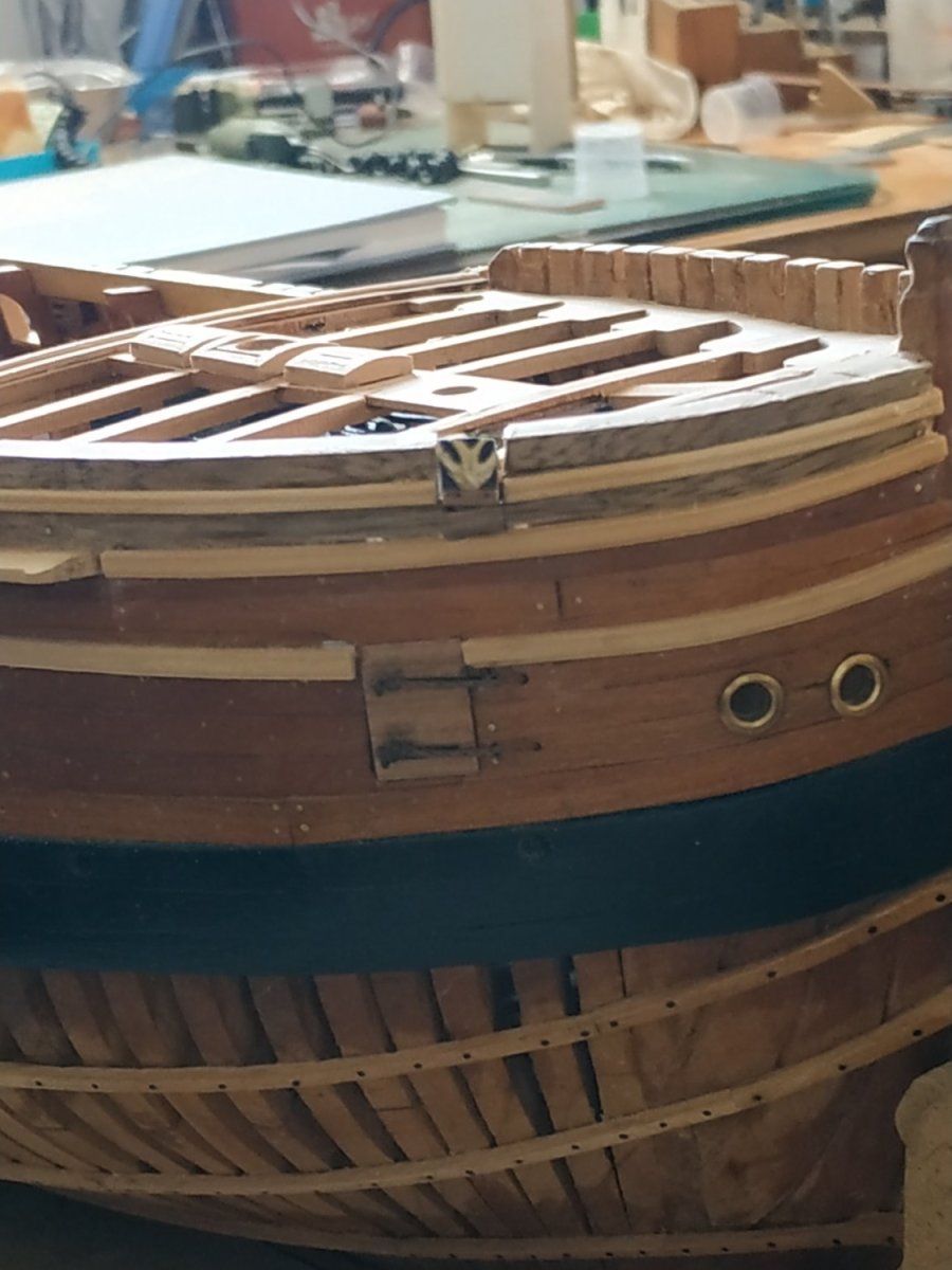
Coamings to the Steam Gratings TFFM refers to how previously made, which like the idiot I am, used the same size strips. These however are only about ⅔ as wide. This became obvious after seeing again the small size of the gratings. I used a similar depth however, to allow for the pronounced roundup of the Head Lodges. The Gratings themselves are also much narrower- too narrow for my thinnest table saw blade. I used some precut gratings from an old kit that are more to scale. The overall size and positioning seem to vary amongst patterns, plans and other builds I have seen. The middle coaming is for the Cowl base. It was a metal plate, but both 3D rendering and D. Vardas show it rounded up similarly to the Gratinga. Therefore, the solid block I used. This Coaming is shown aligned with those fore and aft, but the diameter of my Cowl, necessitates this to be wider

-
Swan-Class Sloop by Stuglo - FINISHED - 1:48
stuglo replied to stuglo's topic in - Build logs for subjects built 1751 - 1800
The Cathead. This requires cutting through the hull-I hate “destroying” what I’ve built. Mistakes not always amenable to invisible repair and I haven’t found a way to turn the clock back. The inboard section is angled upwards and curves outwards relative to the straight outboard section. This ”Tail” section is slightly tapered. It passes beneath the 2# Beam and 3# Beam,where it rests against the Foretopsail Bitt Pin. Where it passes beneath the beams, the beam and cathead are notched. ( something else I forgot to prepare before fixing the beams. This was remedied but again, better to do “off” model.) The outboard part seems rectangular rather than square in section according to the pattern given in TFFM, but the decorative cap is square. When fitted, the upper surface of the sub-deck section should be horizontal, which gives the angle of the outer section - this appears about 15 deg. I took a blank of 95x15x10 mm, stuck the cutout patterns, and shaped the piece. The notching or scoring of the Cathead and beams marked by laying the former on top of the beams. The direction of cut for a window through the hull can be made and the lower level and adjoining Lodging Knee, filed down to allow for the angle of the Cathead at this point. Having milled the scoring in the Cathead, and underscored the beams with chisel and a thin sandpaper strip, I tried to insert the cathead through the hole in the hull. This was impossible. ***As my wife was in another room, I had no one to blame but myself*** The simplest solution seemed to remove the small section above the opening . I later checked out Dan Vardas blog/ He had the same problem. His solution was to remove and remake #2 beam. (I don’t check out this blog every time because the quality of the work and ingenuity of his solutions, make me feel most inadequate) Also I wonder if there should not be a space above the Cathead, to allow for its various ropes. The pair of Sheave holes toward the outer end of the Cathead. The Sheave diameter is 4.77mm, 0.73 wide (My holes became oversize during finishing) The end of the Catshead is finished with a decorative cap- mine didn’t work out as planned. More of that next time

-
Swan-Class Sloop by Stuglo - FINISHED - 1:48
stuglo replied to stuglo's topic in - Build logs for subjects built 1751 - 1800
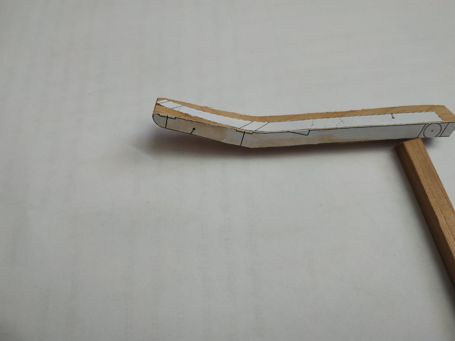
Bowsprit and Foremast Partners. Planks, 1.06mm thick, sit flush on rabbets of respective Beams.(these rabbets would have been made on the mill before fixing the beams, but to unglue everything was a bit too much) Holes for mast, both less than the 9.4mm suggested- final sizing and position I think better left until after planking. The Bowsprit hole, angled according to plan. Half Hook Basis for planking and waterways, between the Bowsprit Partner and 1st Beam. 2.12mm thick and rabbeted on adjoining structures.
-
Swan-Class Sloop by Stuglo - FINISHED - 1:48
stuglo replied to stuglo's topic in - Build logs for subjects built 1751 - 1800
Forecastle Deck Carlings They run fore/aft and define the various openings of the deck. 2.12x2.65mm except for the Bowsprit Partner 2.12x3.29mm, to give support to Half Hook and planking as suggested by TFFM. Noted that no Carlings to support Foremast Partner.This is relatively thin but surely the forces on it are not much less than the lower decks even if the weight on the deck is less. Forecastle Deck Ledges Similarly, few in number, frame the steam gratings and galley chimney cowl. 1.86x1.6mm