Mahuna
-
Posts
1,504 -
Joined
-
Last visited
Content Type
Profiles
Forums
Gallery
Events
Everything posted by Mahuna
-
 Welcome back, Rich!
 -
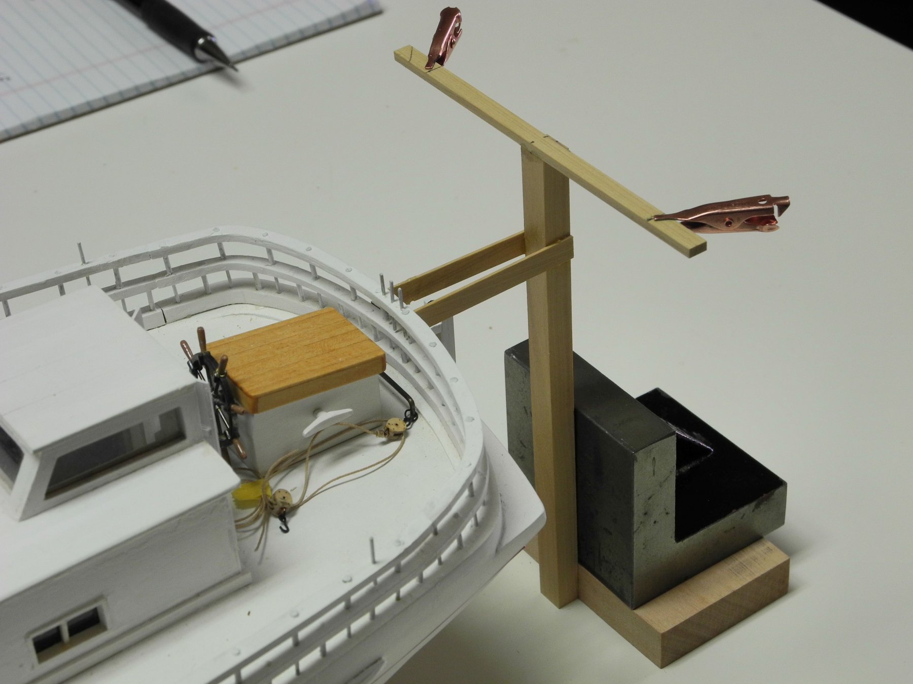
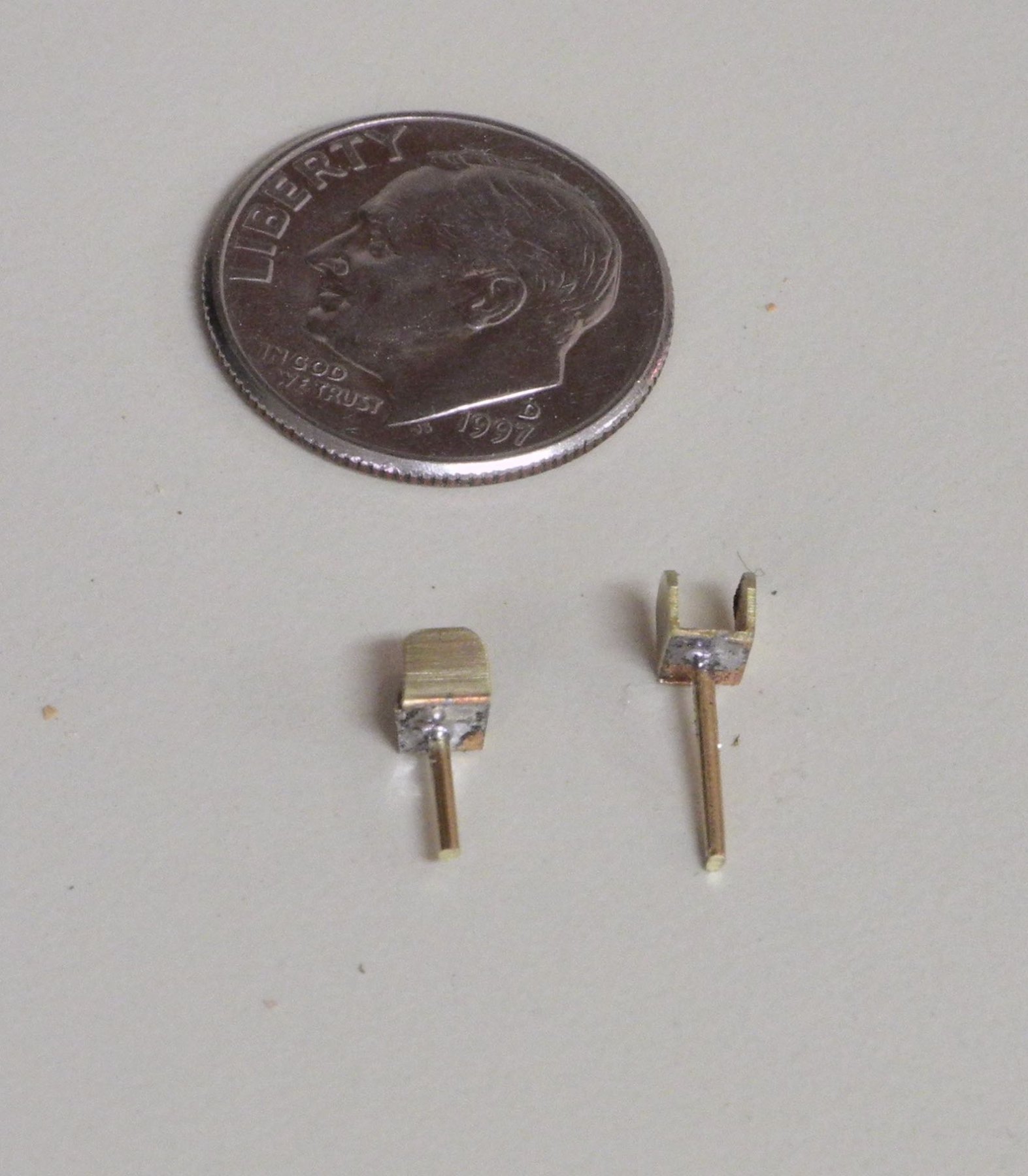
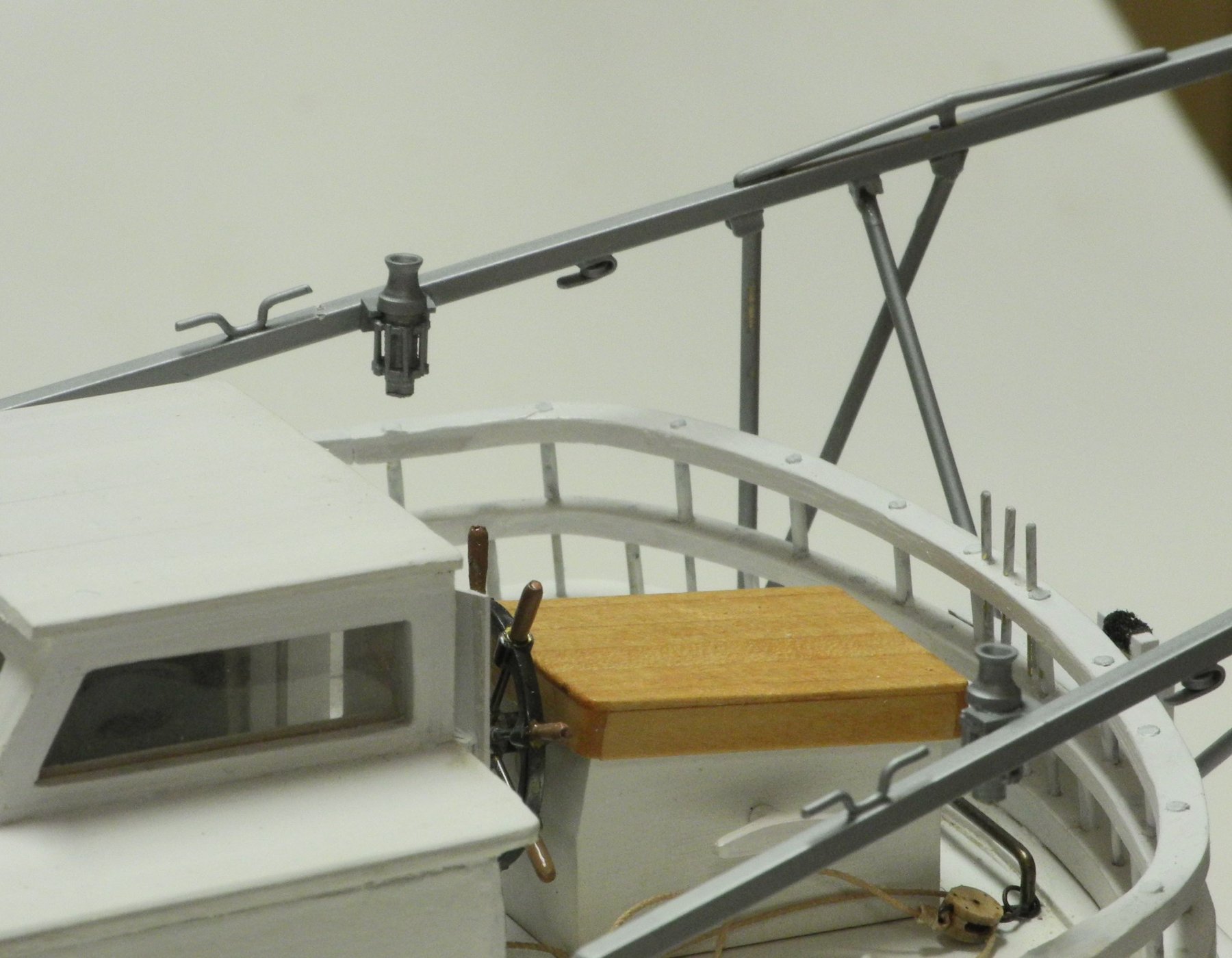
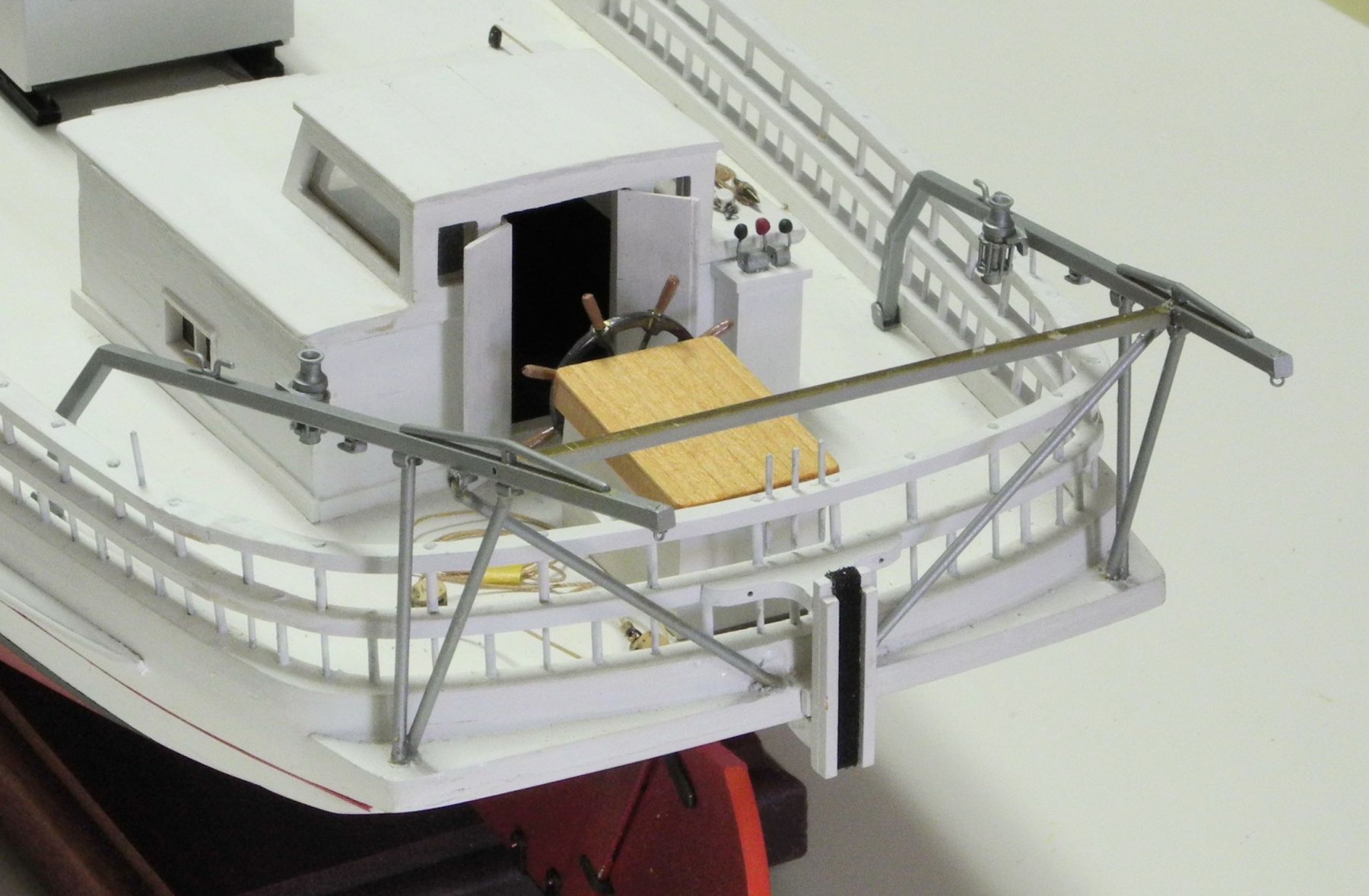
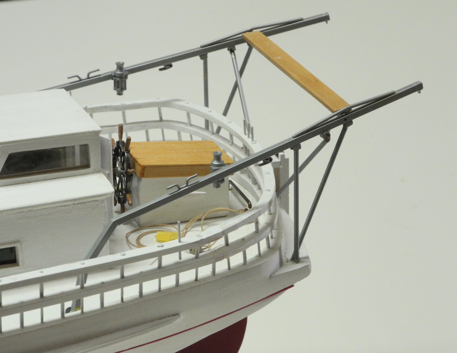
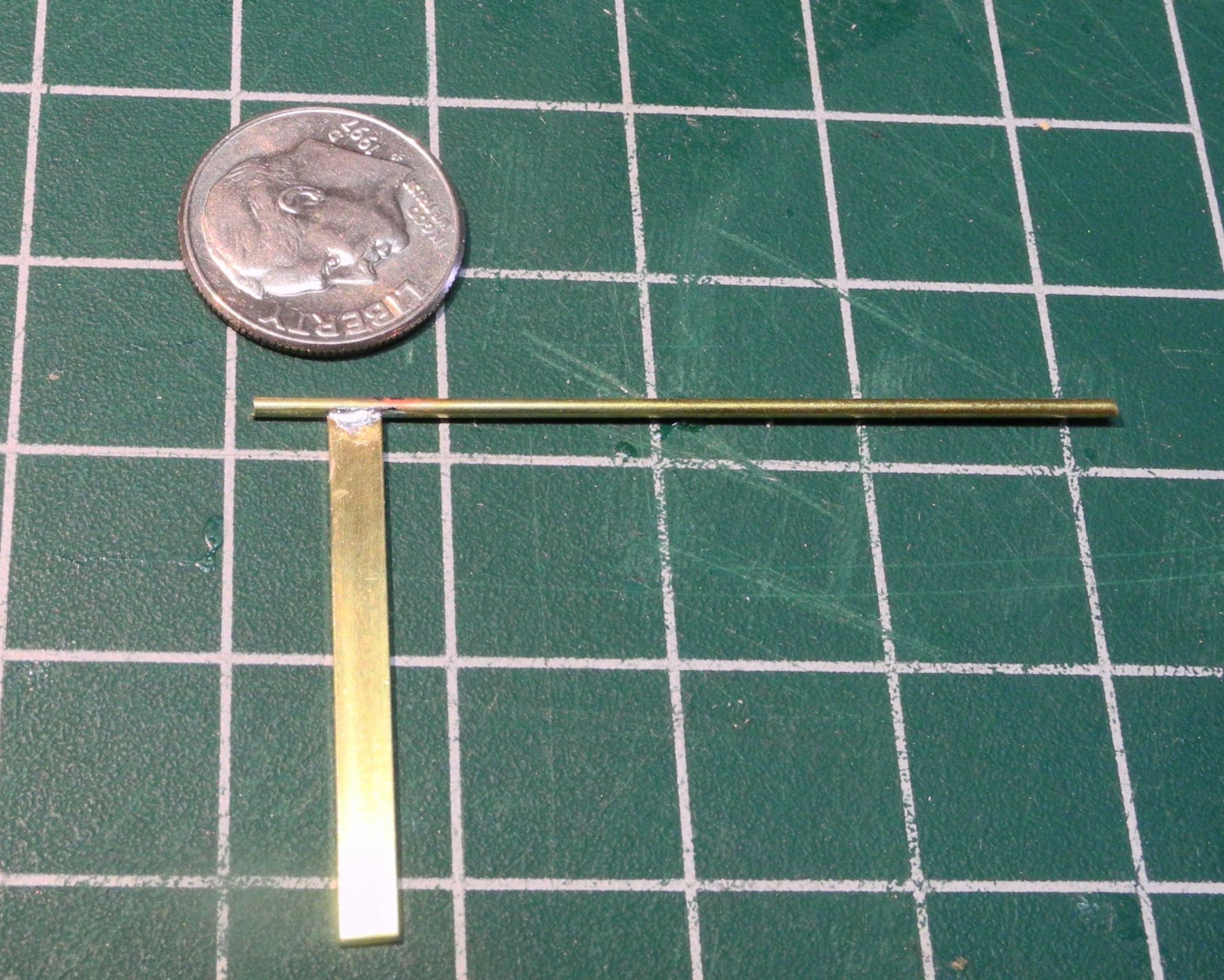
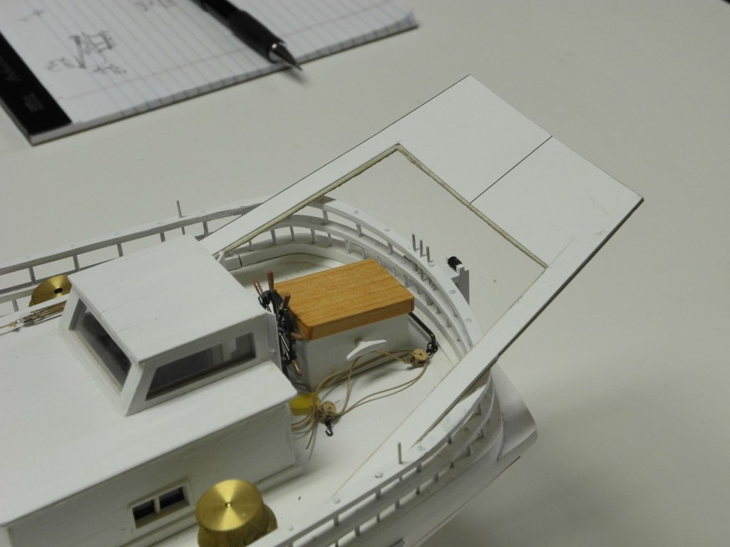
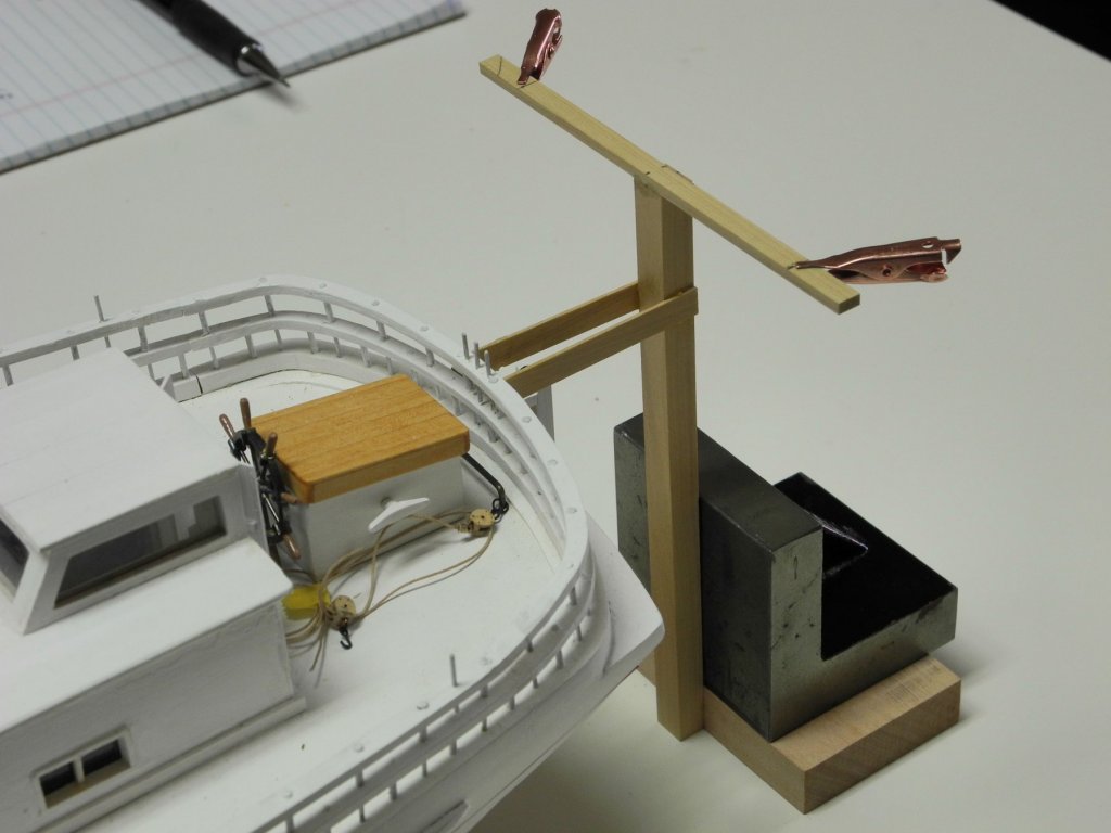
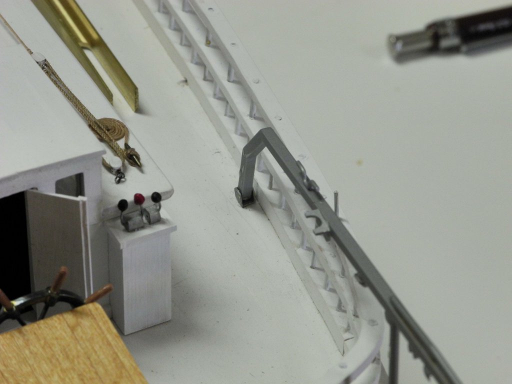
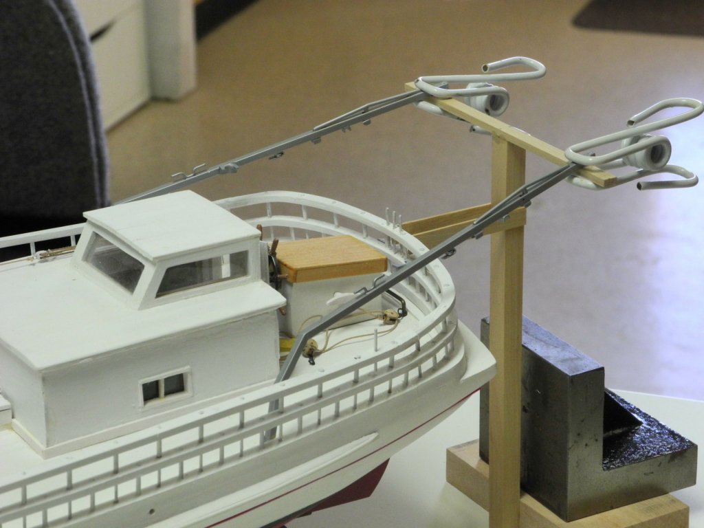
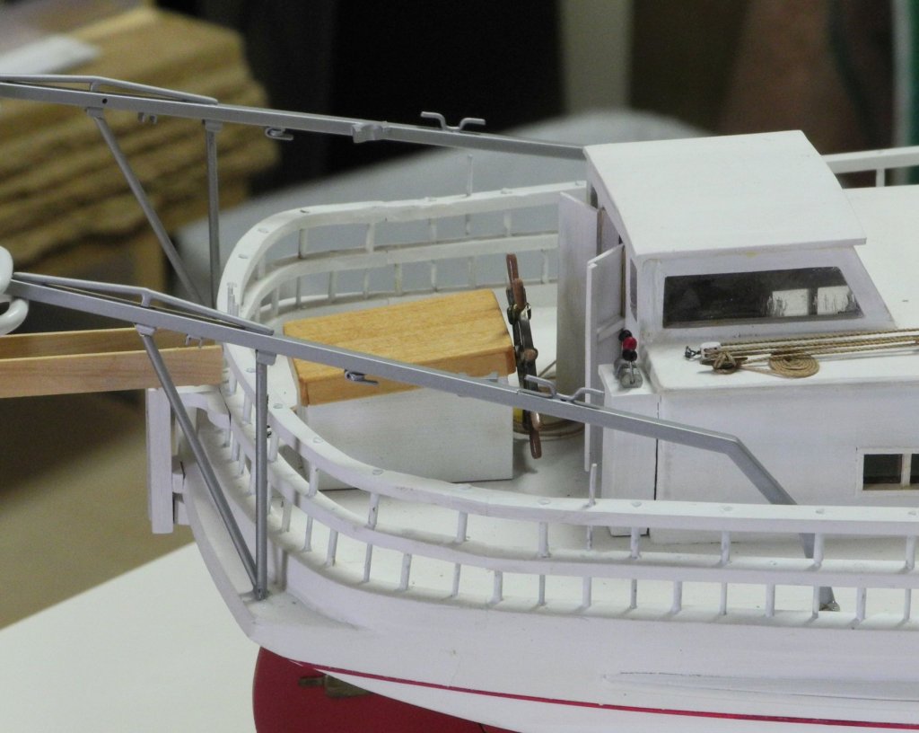
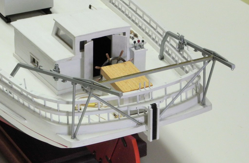
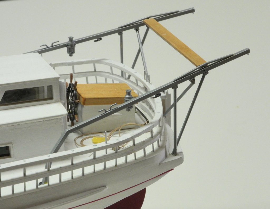
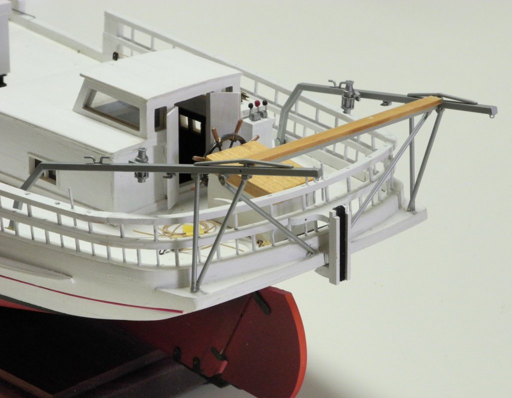
Part 61 – Pushboat Davits cont’d The brass parts of the davits were painted because it was very difficult to get a uniform light color using the JAX Flemish Black. The painting process consists of the following steps (any handling of the brass parts is done while wearing latex gloves to keep from getting body oils on the brass): First, clean the brass part by soaking in lacquer thinner for 30 minutes. Next, scrub the part with soapy water and rinse thoroughly. Then soak the brass part in white vinegar for an hour or so. This slightly etches the part to provide ‘tooth’ so the paint will adhere. Rinse the part thoroughly after this step. Paint with a primer – Tamiya grey primer was used for this step. Let the primer cure overnight. In the above photo, the winches are held in place by two-sided tape. Paint with the final color. I used Bare Metal in a spray can from Tamiya. Again, let the paint cure overnight. As a final step, I sprayed a coat of Dullcoat on the parts. This helps protect the finish, and eliminates any glossy appearance. After all of the parts were painted, the davits were ready for installation. A jig was used to ensure that the davits were set at the proper angle as shown in the HAER drawings, and that they extended far enough to properly support the pushboat. The first photo shows a drawing, glued to thin plywood, that was used to lay out the davits. The jig shown in the following photo was used to support the davits. The jig was made so that a crossbar would support the ends of the davits at the appropriate height, and the wood pieces extending forward from the vertical post ensured that the jig was at the proper distance from the outside edge of the cap rail. The weight at the base of the jig ensured that the jig was held in place during the assembly process. Two small seats were made to support the forward end of the davits at deck height. These seats were made from 1/8” square brass tube with 1/32” posts for insertion in the deck. The davits were epoxied into the deck seats and the aft ends of the davits were clamped in place. A perpendicular strut holds each davit in place. These were epoxied to the aft ledge and to the forward bracket on the davit. Another vertical strut slants from the aft bracket on the davit to a point adjacent to the perpendicular strut, and was epoxied in place. Finally, diagonal struts were epoxied from the middle bracket to a point adjacent to the pushboat bumper. (The epoxy shown in these photos was later cleaned up and painted over.) The electric winches were hung from brackets that had been made from 1/8” brass angles milled to take the round body of the winch. The new pulleys can be seen just aft of the winches. Finally, a crosspiece connects the two davits. A ‘lazy board’ is installed on top of the crosspiece. A good friend from the Chesapeake area told me the name of the board: “As usual no one knows why, but one old timer told me if you felt lazy you could lie down on it [pretty precarious perch I think.] (there is a photo somewhere of a guy doing that.) Another said it provided a lazy-man's way to get in and out of the push boat. He did not tell me the non-lazy way.” This completes the installation of the davits, although some cleanup of the epoxy and some painting touch-up still remains. This was a fairly complex installation that I was concerned about, but I’m pleased with the results. I’m not sure when I’ll hang the pushboat from the davits – I still need to decide whether to make my own blocks or to use commercially available ones (likely from Syren) for the rest of the rigging. Meanwhile, there is quite a bit of metalworking still ahead – including the propeller for the pushboat. Thanks everyone!


- 878 replies
-
- 20
-

-
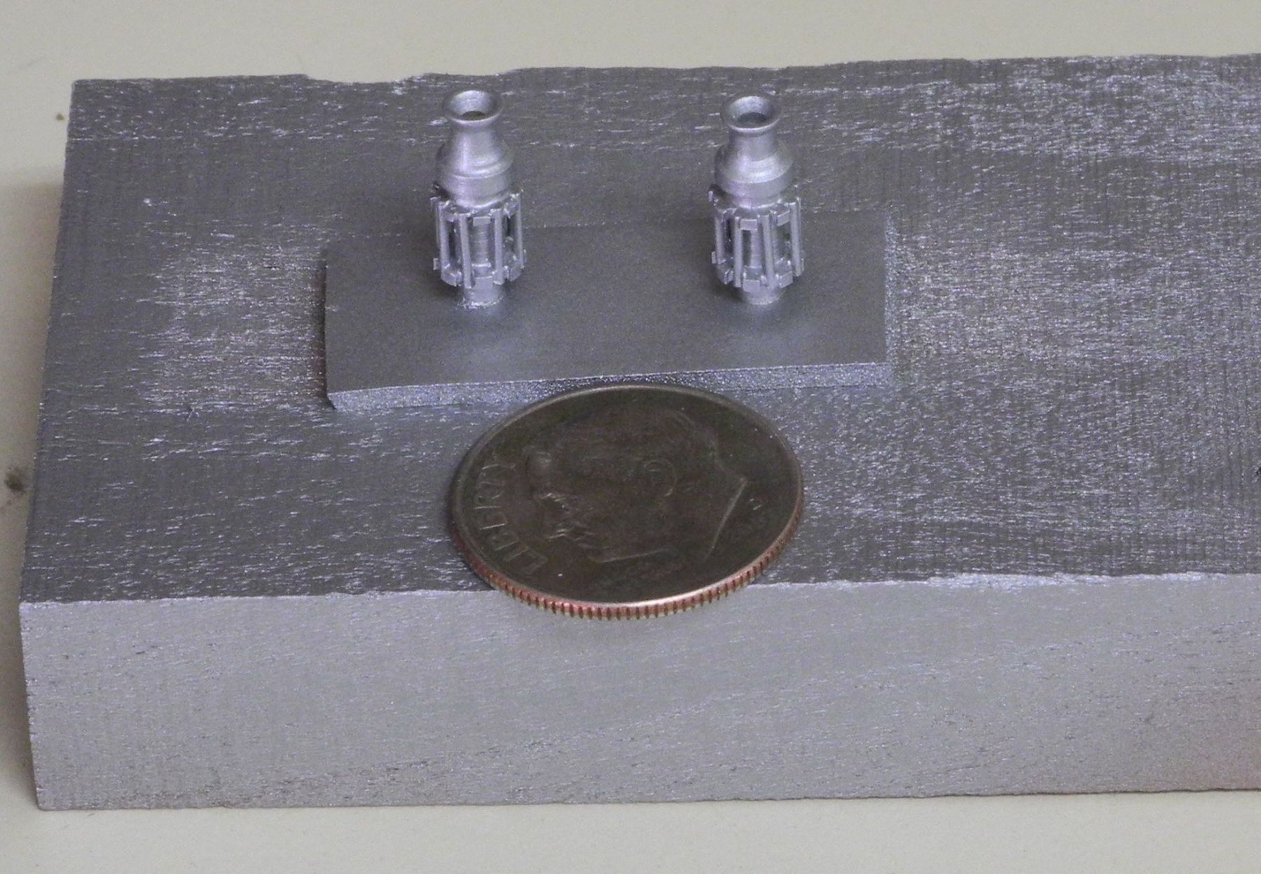
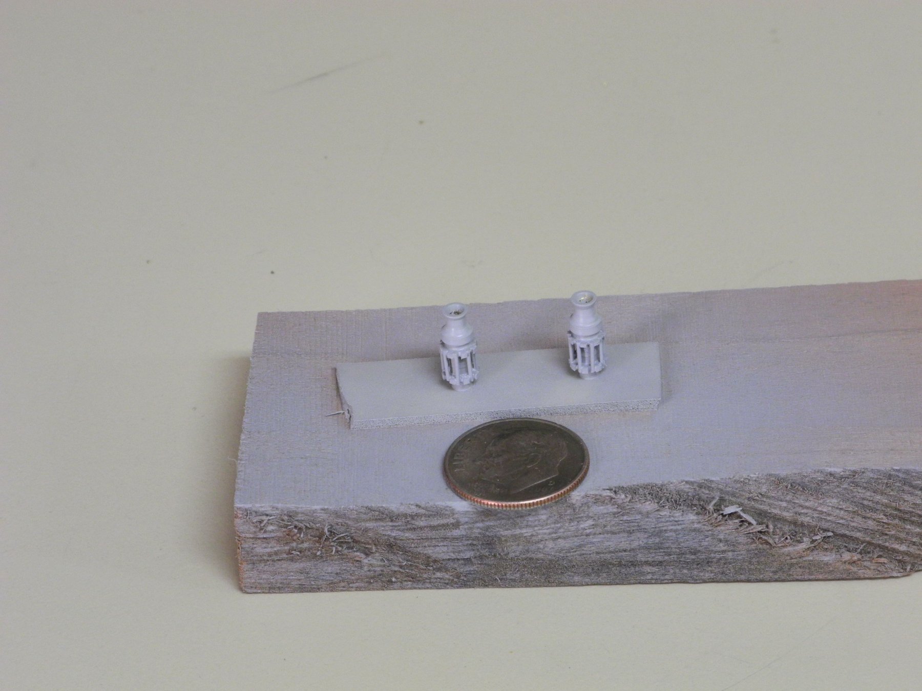
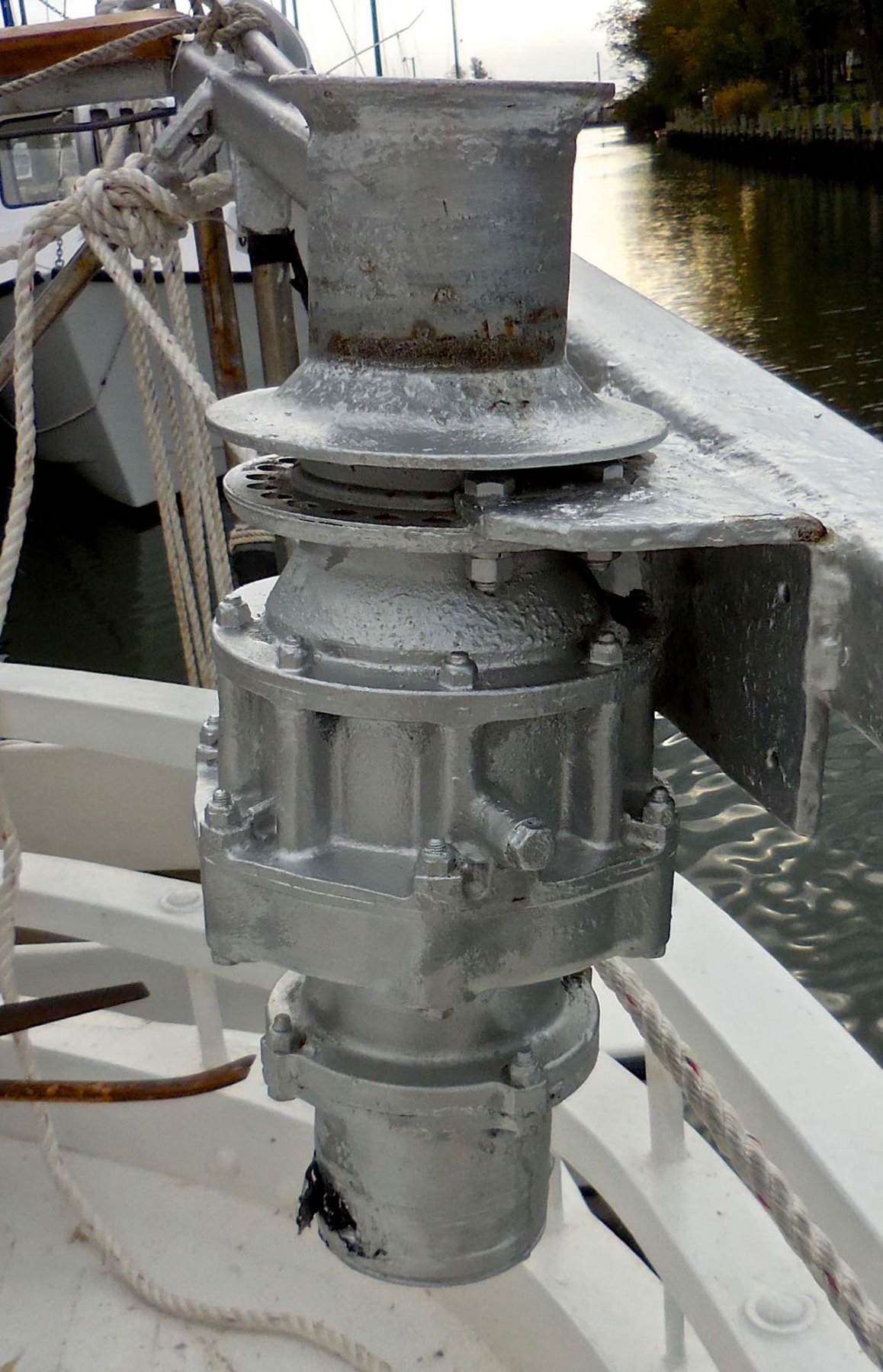
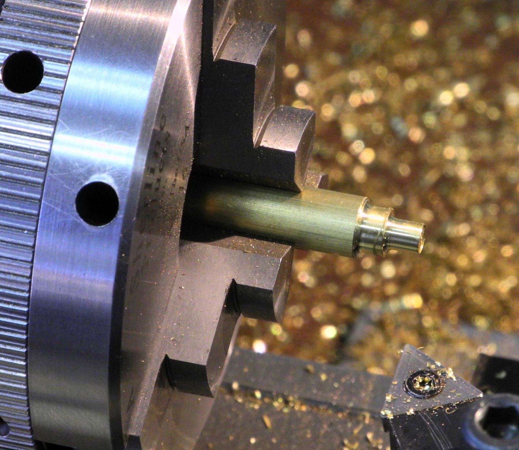
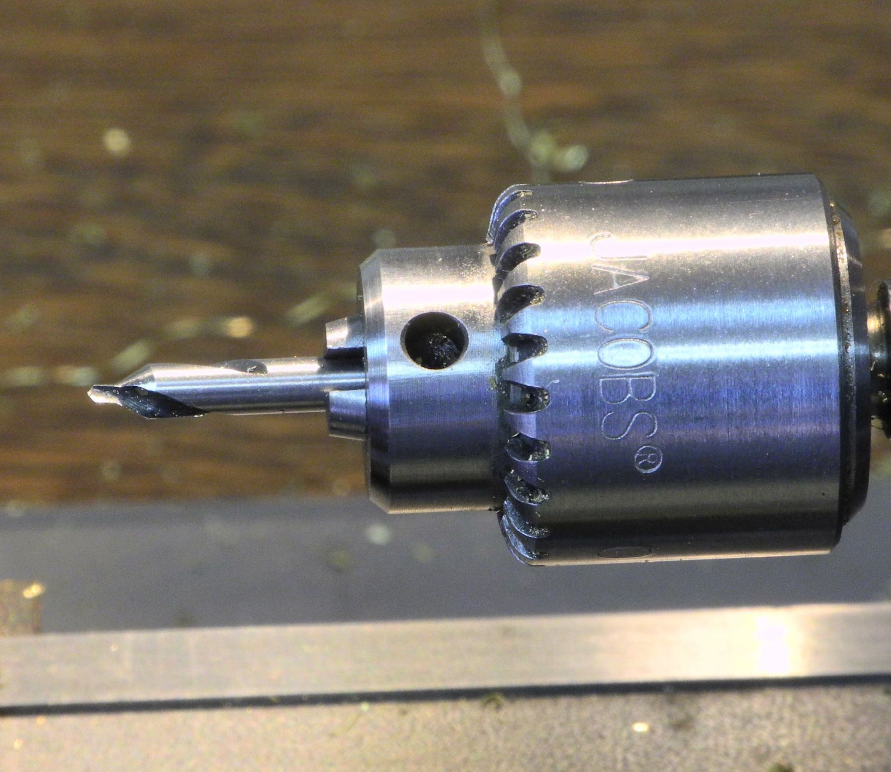
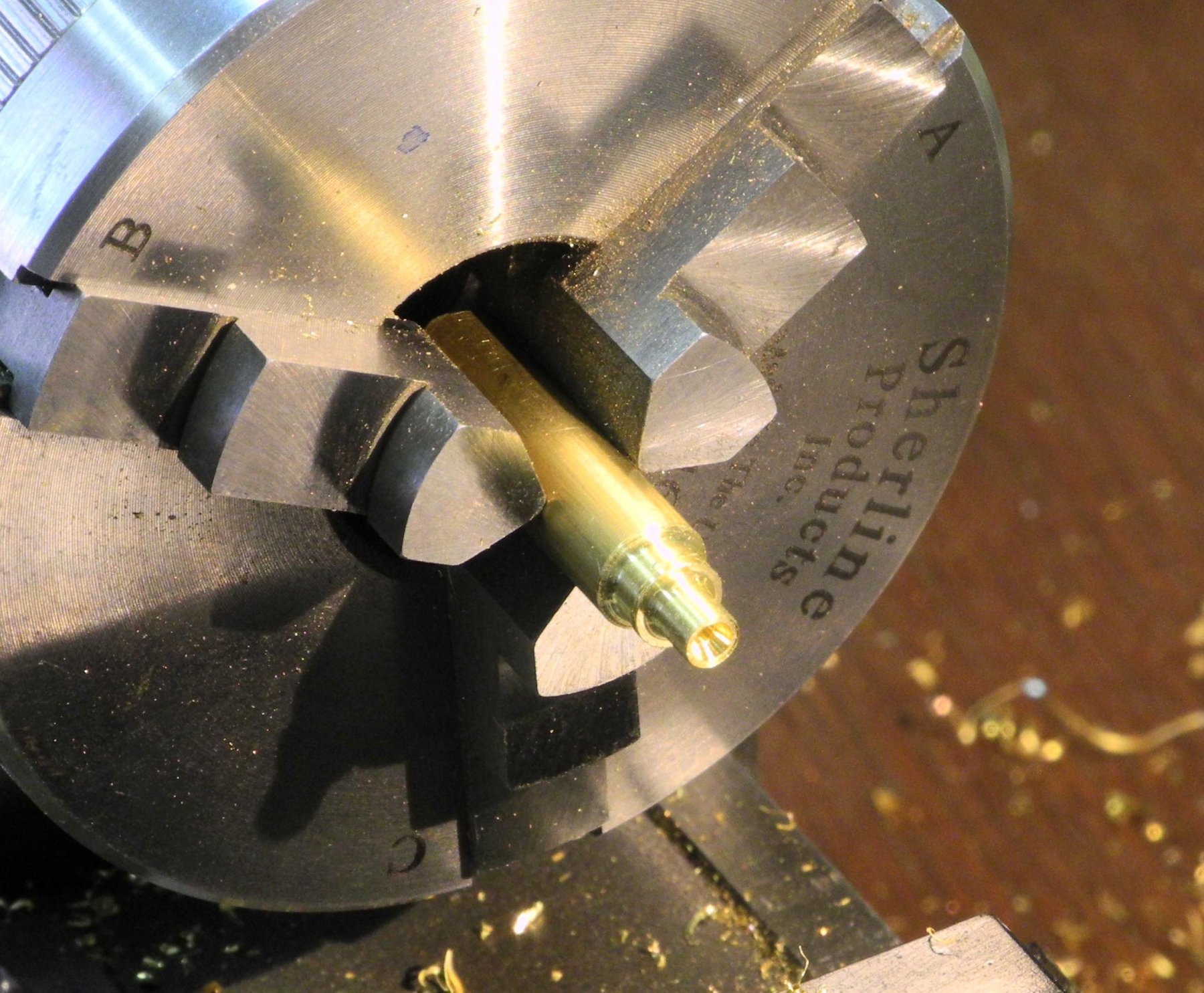
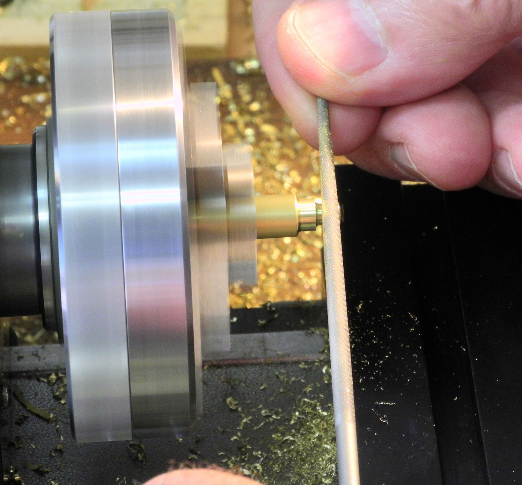
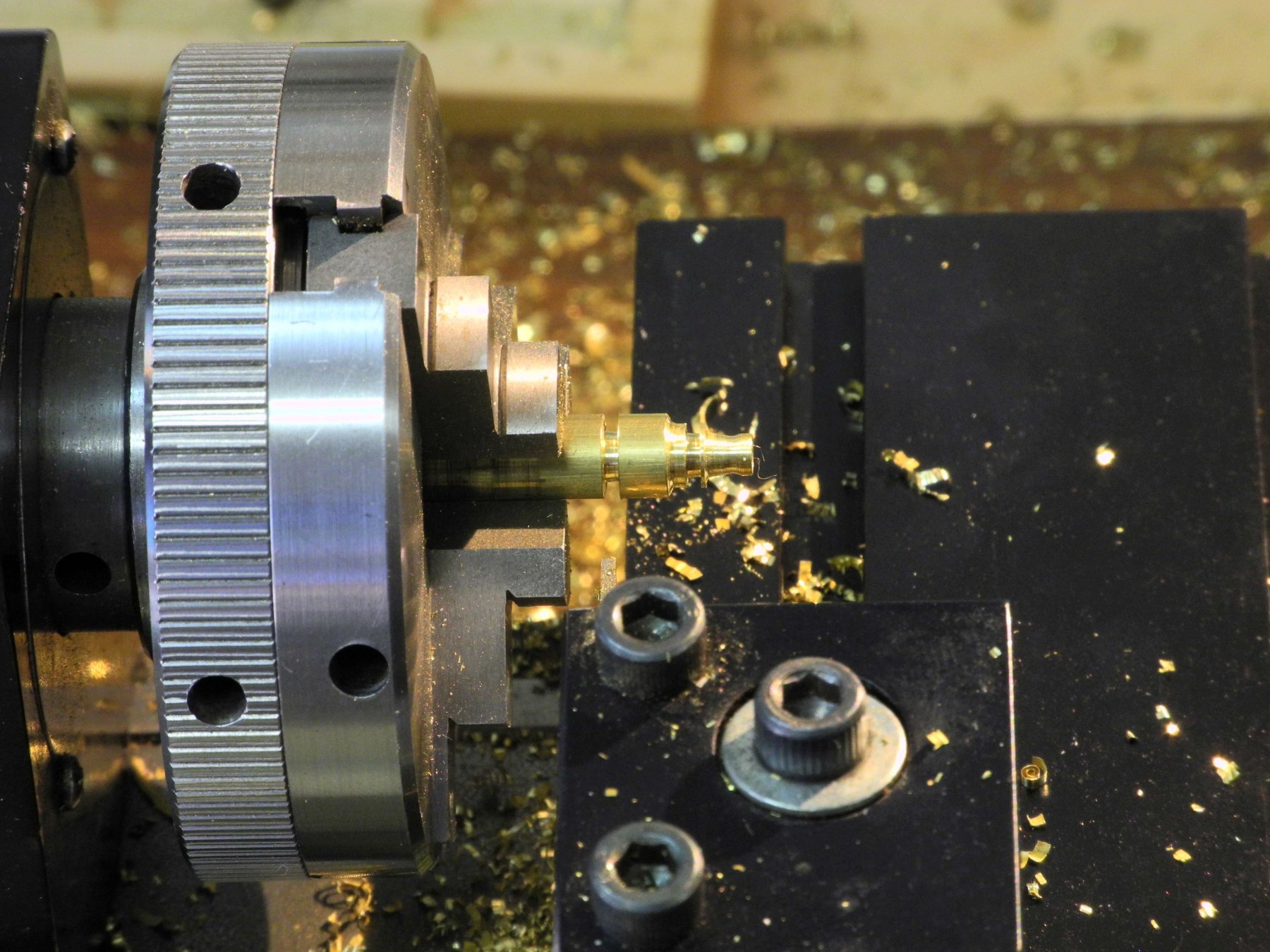
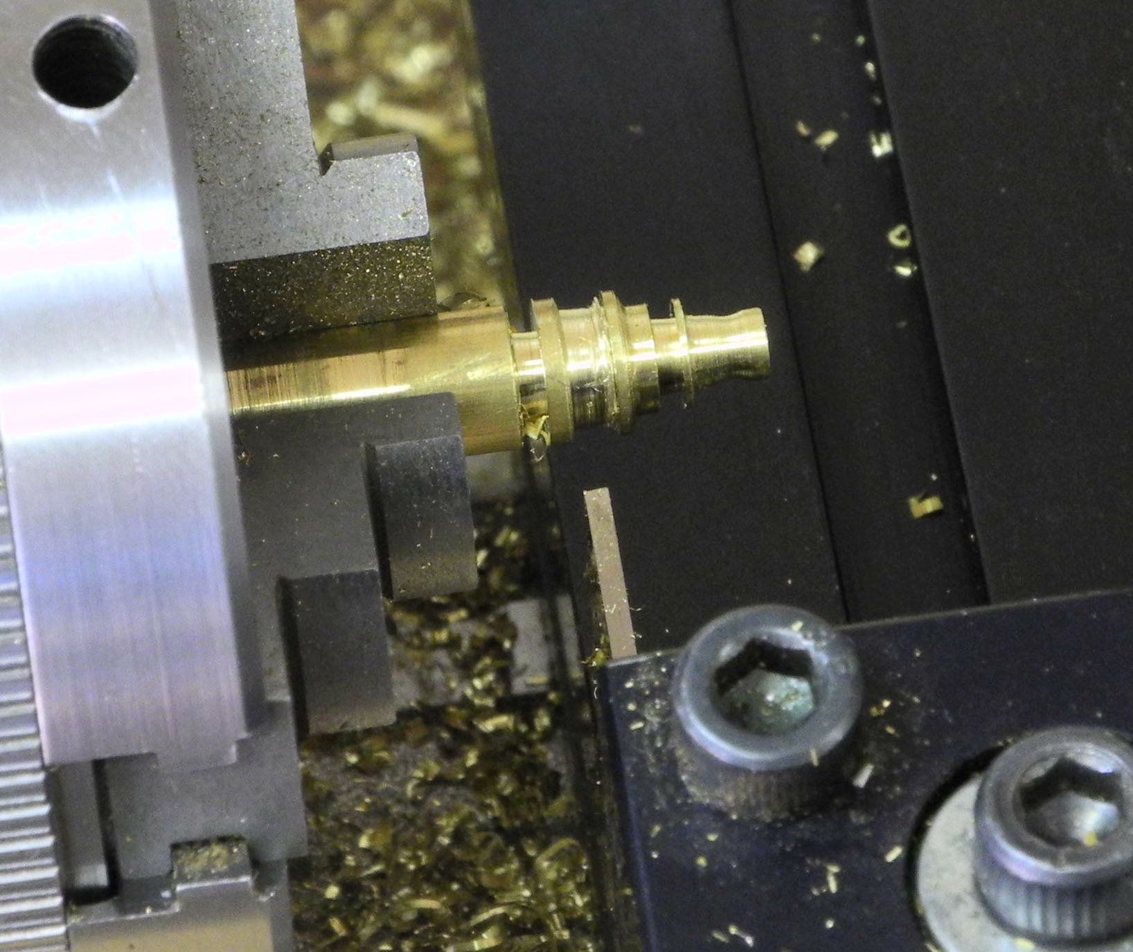
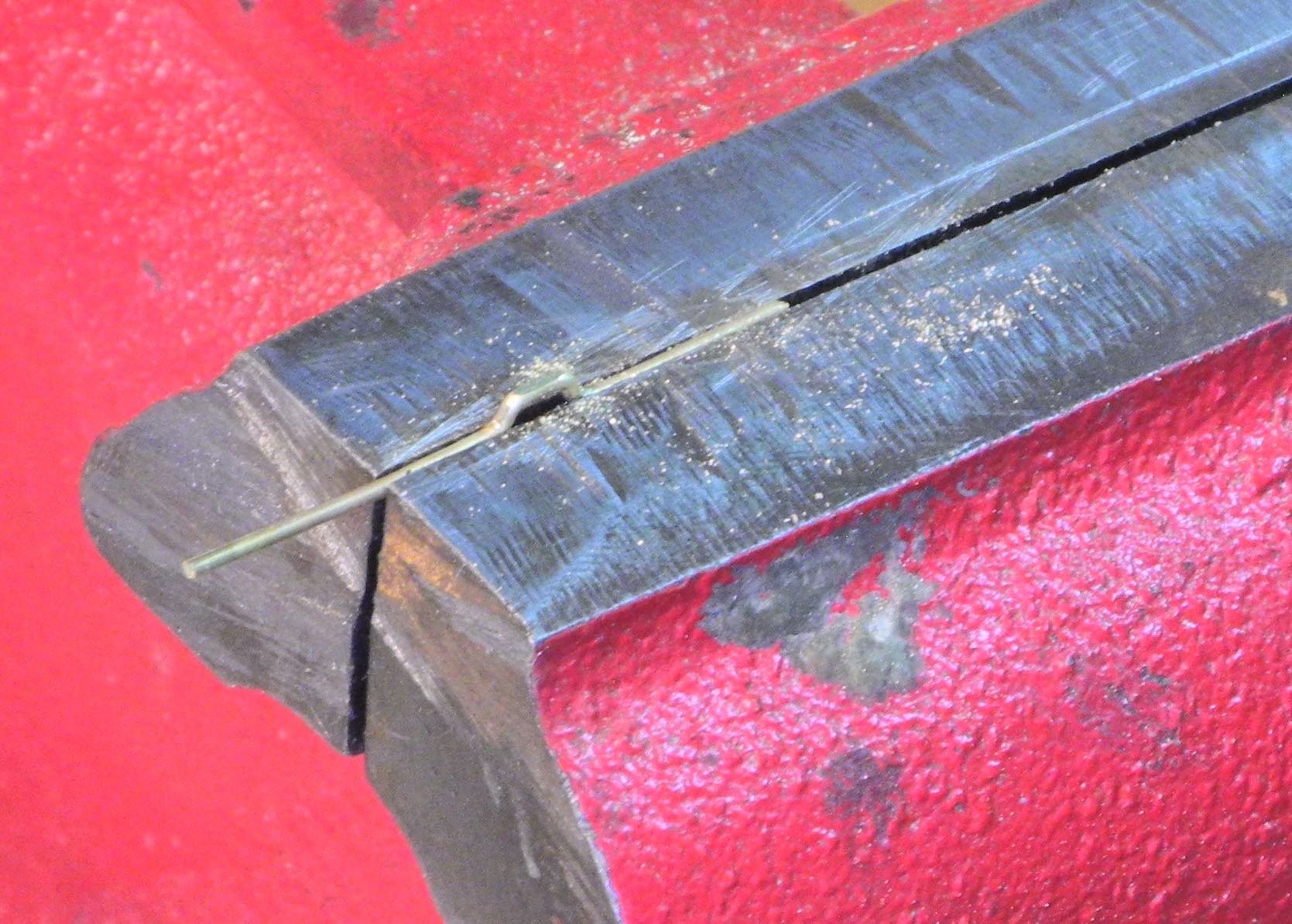
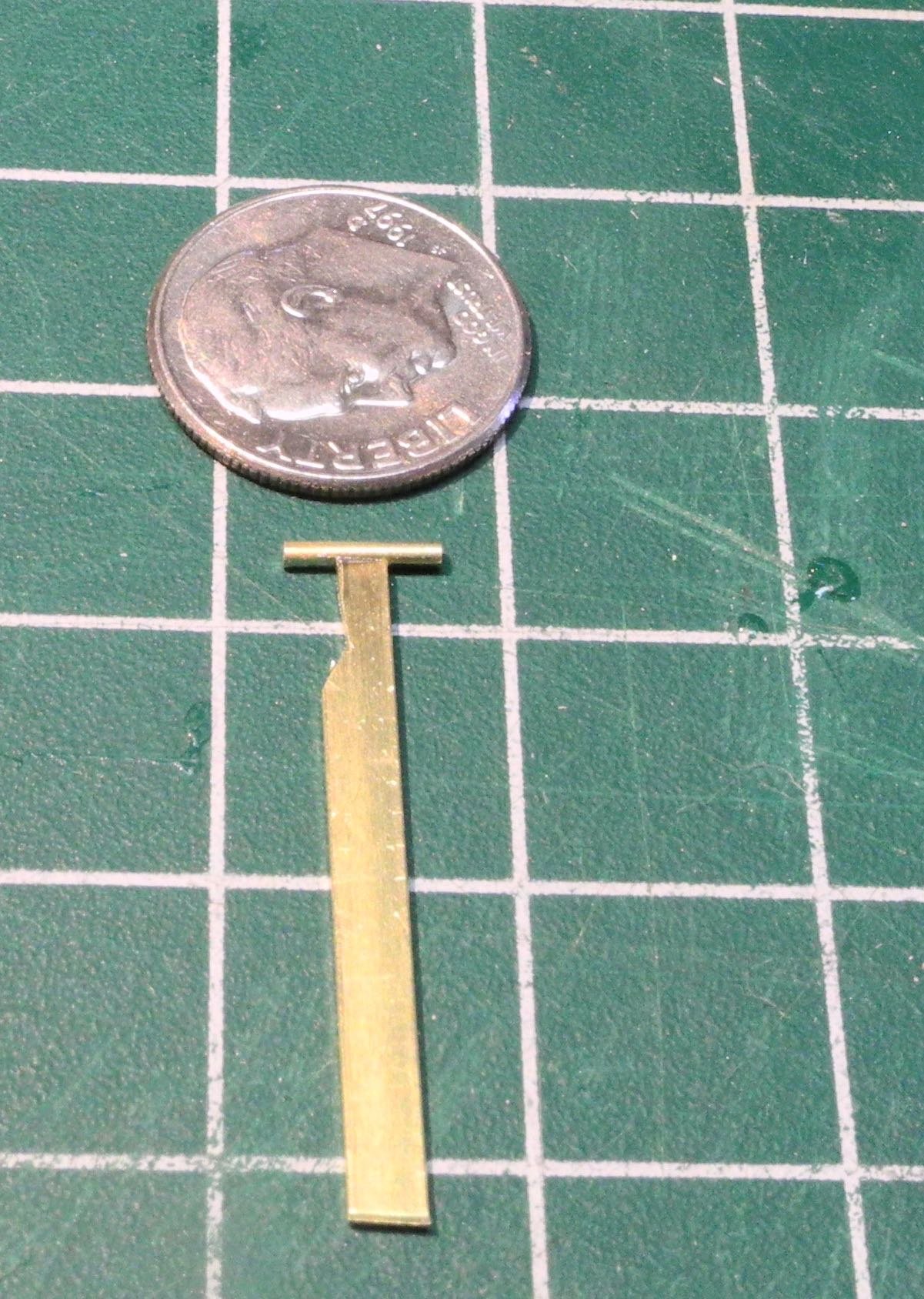
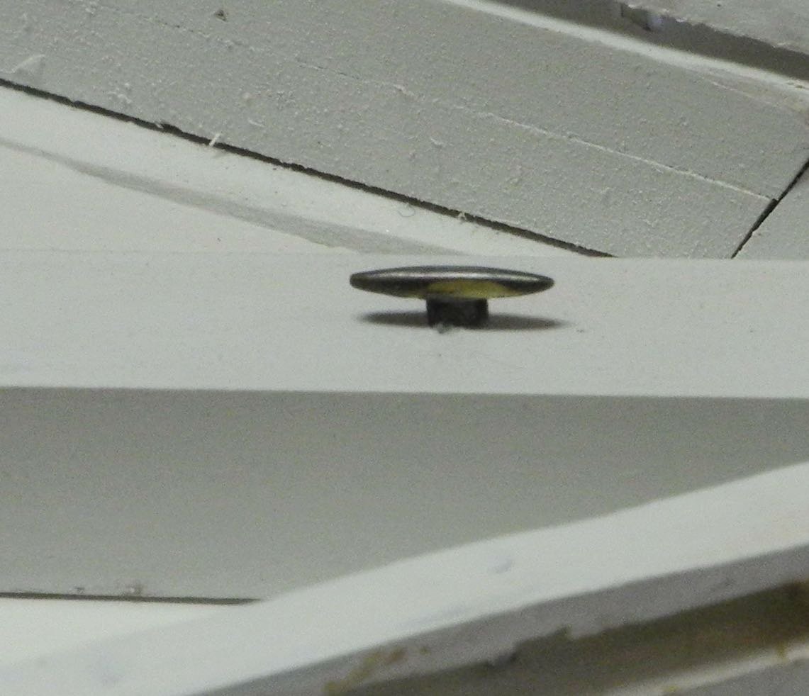
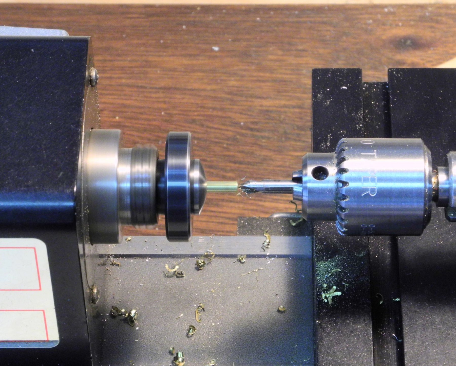
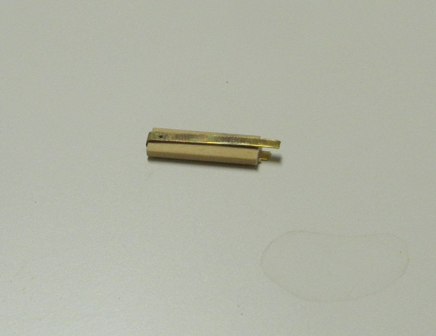
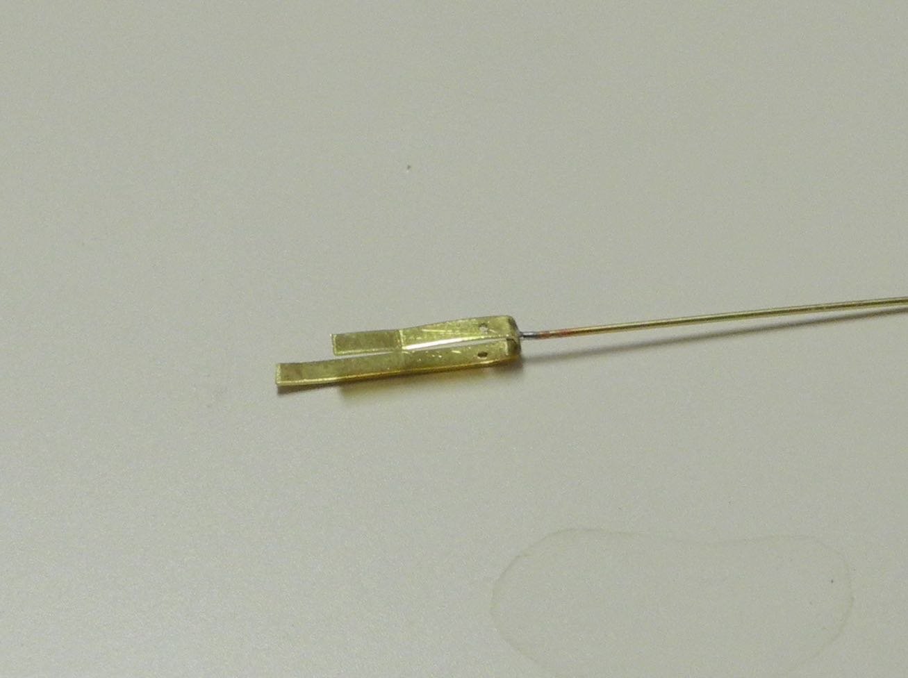
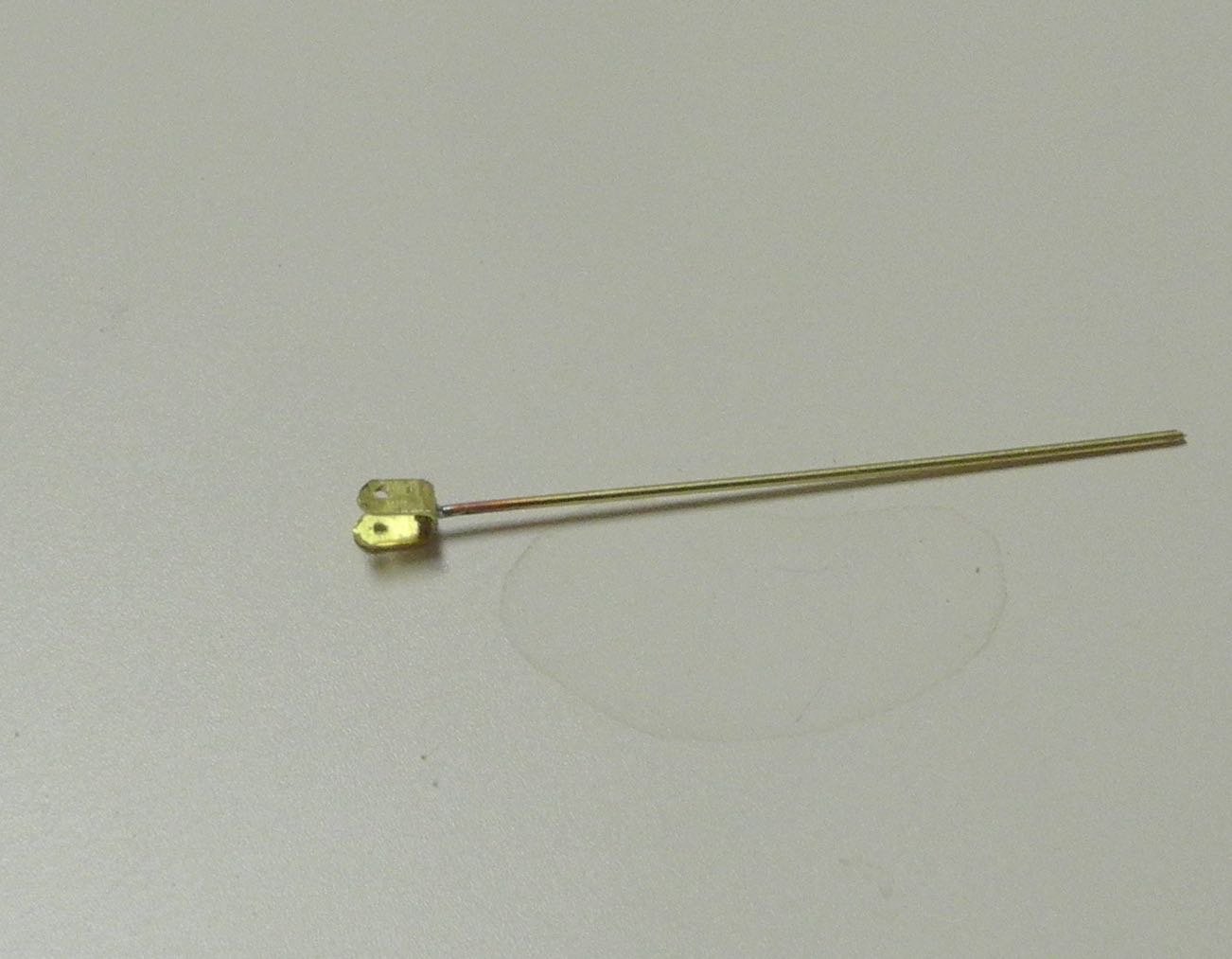
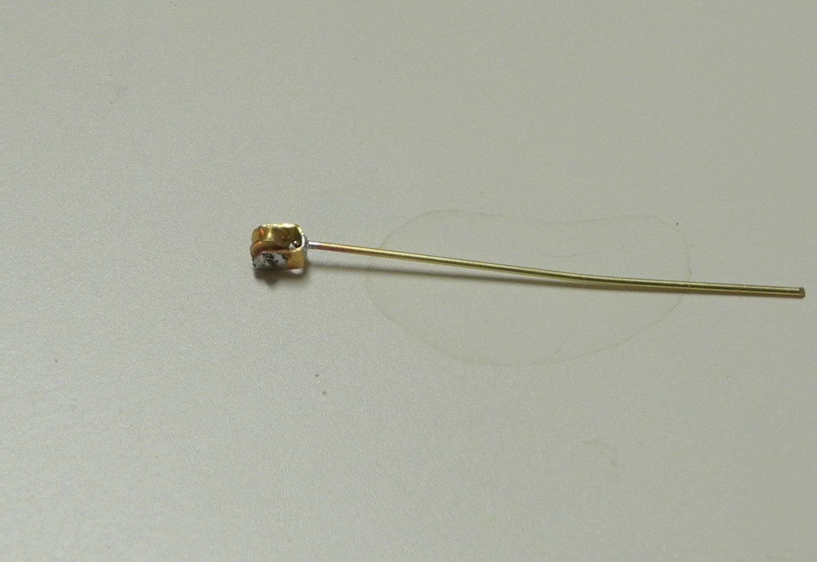
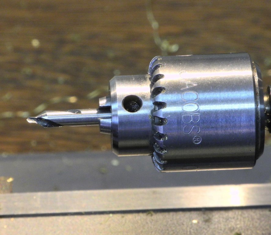
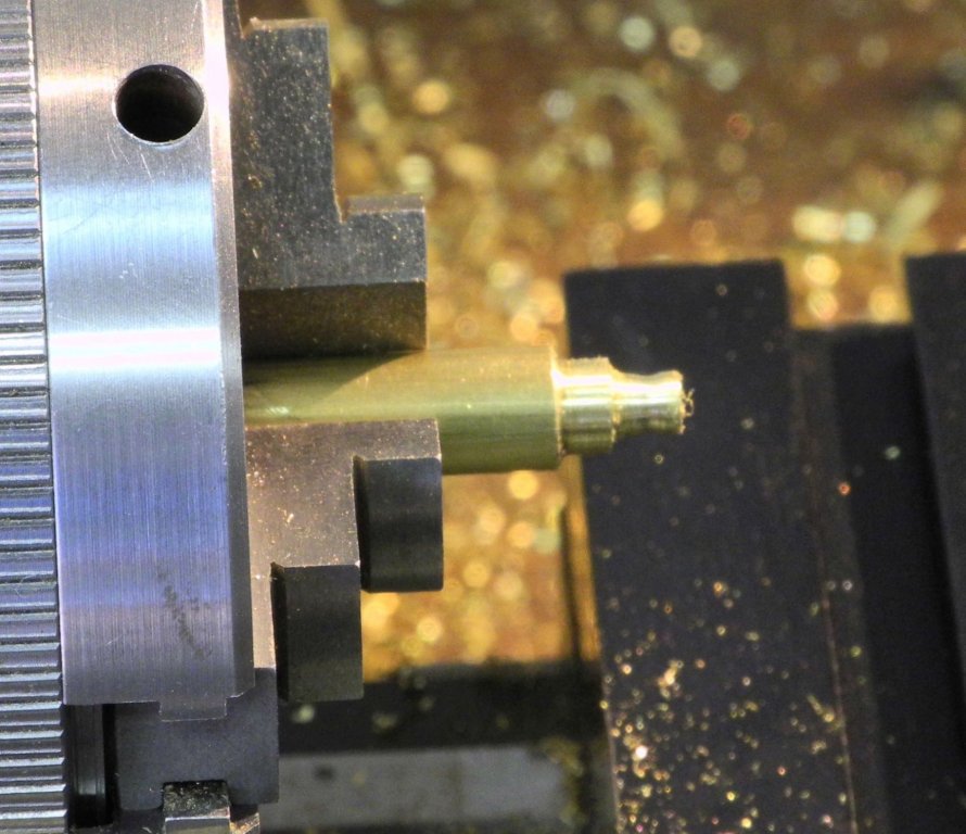
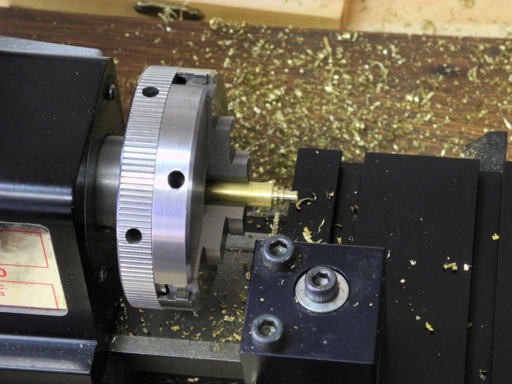
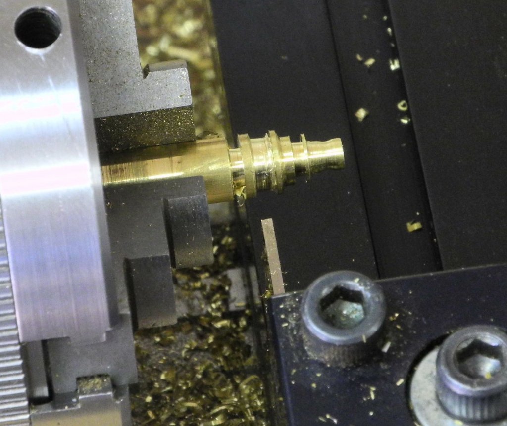
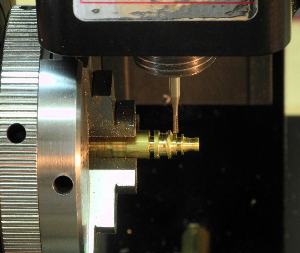
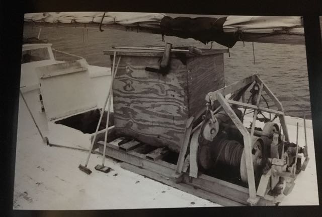
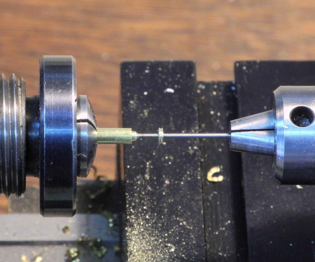
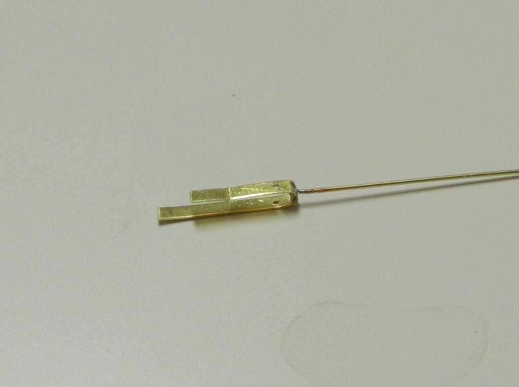
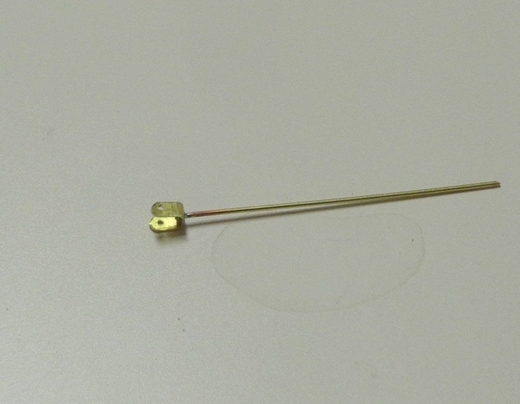
Part 60 – Pushboat Davits cont’d In the last post, I mentioned that there were still some decisions that needed to be made about the davits on the model. Will the electric winches be on the model? Will I add a pulley that can be seen on the underside of the davit? Most importantly, how will the davits be colored to match the aluminum color? I decided that the winches should be on the model, since they were present during the HAER review and I had already decided that the model should look like Kathryn looked during the review. I did add the pulleys for the same reason. And, after some internet searches on painting brass, I found some good information from a couple of model railroading forums, and I found some Tamiya paint that would provide the look that I wanted. First – the electric winches. By the way, I noticed in the ‘Working Skipjacks’ book that there are photos of the pushboat being hauled by the crew without using the winches. I got in touch with Kathryn’s owner and asked him why this was so. He said that even though the winches are supposed to run off battery power they often don’t work – probably because of water getting into them. The following is a photo of one of Kathryn’s winches. Using the length of the winch measured from the HAER drawings I was able to estimate the various dimensions of the winch using this photo. I actually made two sets of winches - I needed to make the second set because the first set wound up being to fat. Most of the following photos showing the winch fabrication are actually from that first set, but the process was still basically the same. The final set of winches were made from 3/16” brass rod, and were ½” long. The first step was to reduce the top end of the rod to the dimension of the drum on the top of the winch (1/8” on the model). A center drill was then used to hollow out the drum. The cutting area of the center drill includes a sloped shoulder that can be used as a countersink. This served to hollow out the drum in a cone shape. The drum is concave, and a round file was used to get this shape. There is a flange just below the drum, which is used to mount the winch. This flange was cut using the parting tool. Most of the cuts on the winch were so small that this was the tool used for most of the cutting. The body of the winch is the thickest part, so this was separated out next. The middle of this body area is narrow, and there are a number of bolts visible. The middle of the body was reduced. Drilling holes for inserting simulated bolts was unsuccessful (broken drill bits), so grooves were cut into the rings of the body so that small rods could be used to simulate the bolts. This was done on the rotary table of the milling machine (held vertically). The bolts were made using .0195 brass rod, which were soldered in place. In the above photo the Kool Jool mentioned in the last post was used to protect solder connections. The following photo shows the finished winches. Painting, along with installation of the davits, will be covered in the next post. Thanks everyone, for the likes and comments.


- 878 replies
-
- 14
-
-
Great job, Patrick. With all of those radical curves, I'm sure getting the sides symmetrical was a challenge. Especially at your scale, any little deviation would likely be very noticeable. Kudos!
-
Great progress, Ed. Your work on YA continues to amaze.
- 3,618 replies
-
- 3
-
-
- young america
- clipper
- (and 1 more)
-
Hi Patrick. Very nice progress in such a short time. You've got the hull shape looking really good.
-
Hi Patrick. Yes, rough balsa blocks, but I can see where you're going with the shape. This will be another awesome build from your shipyard.
-
I just found your new build, Patrick, and it looks like you're well on your way to another masterpiece! Looking forward to watching your progress.
-
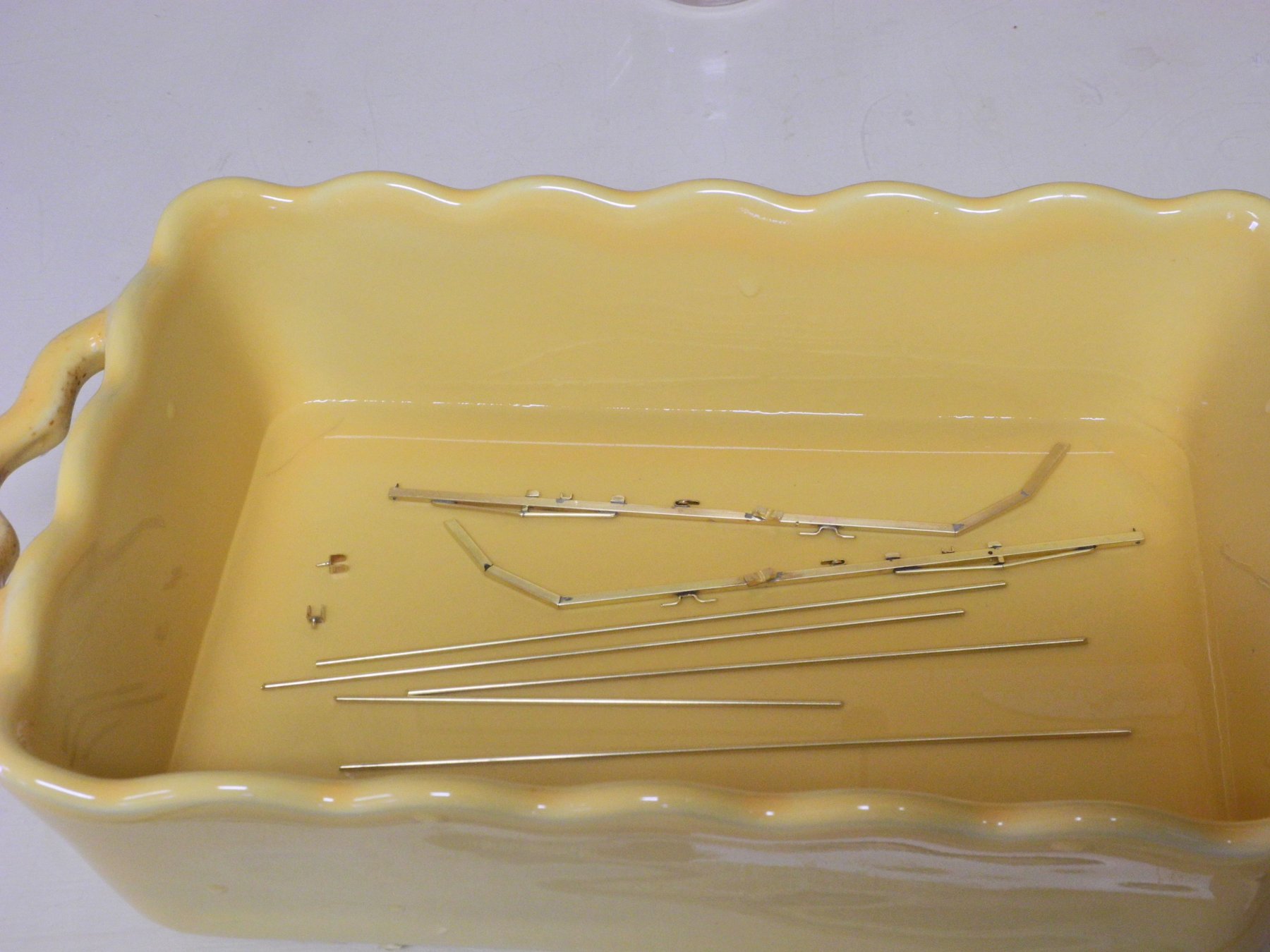
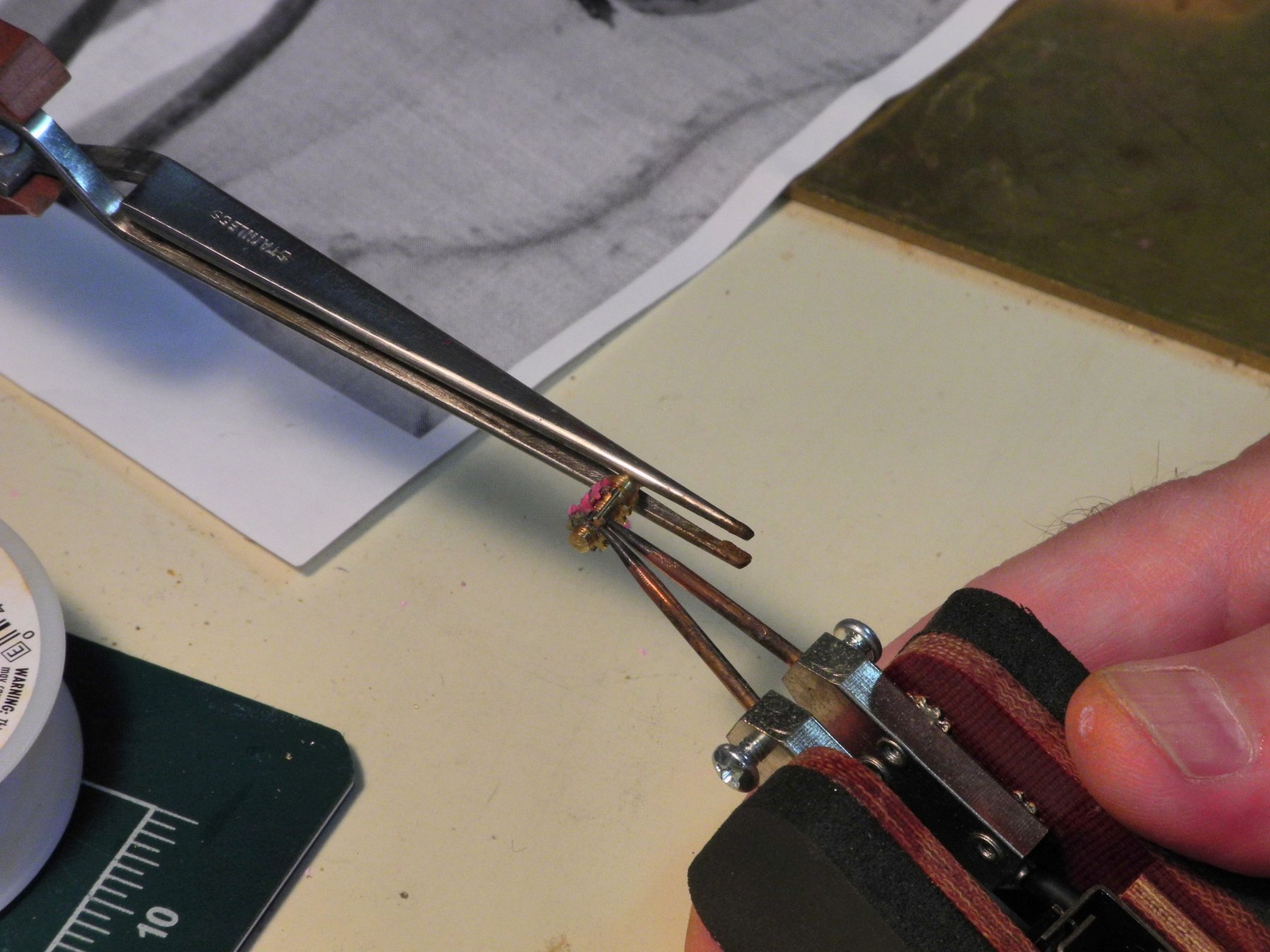
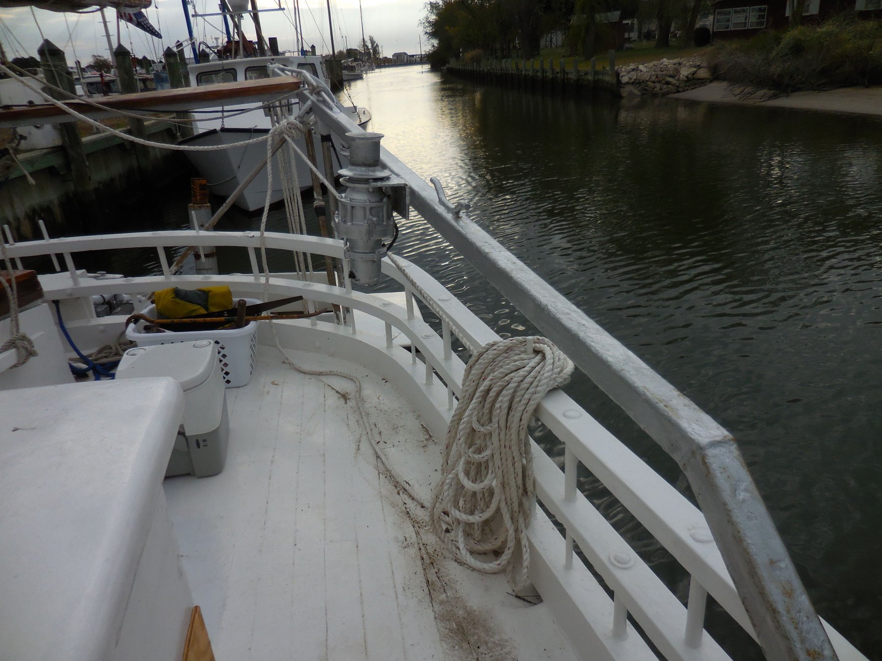
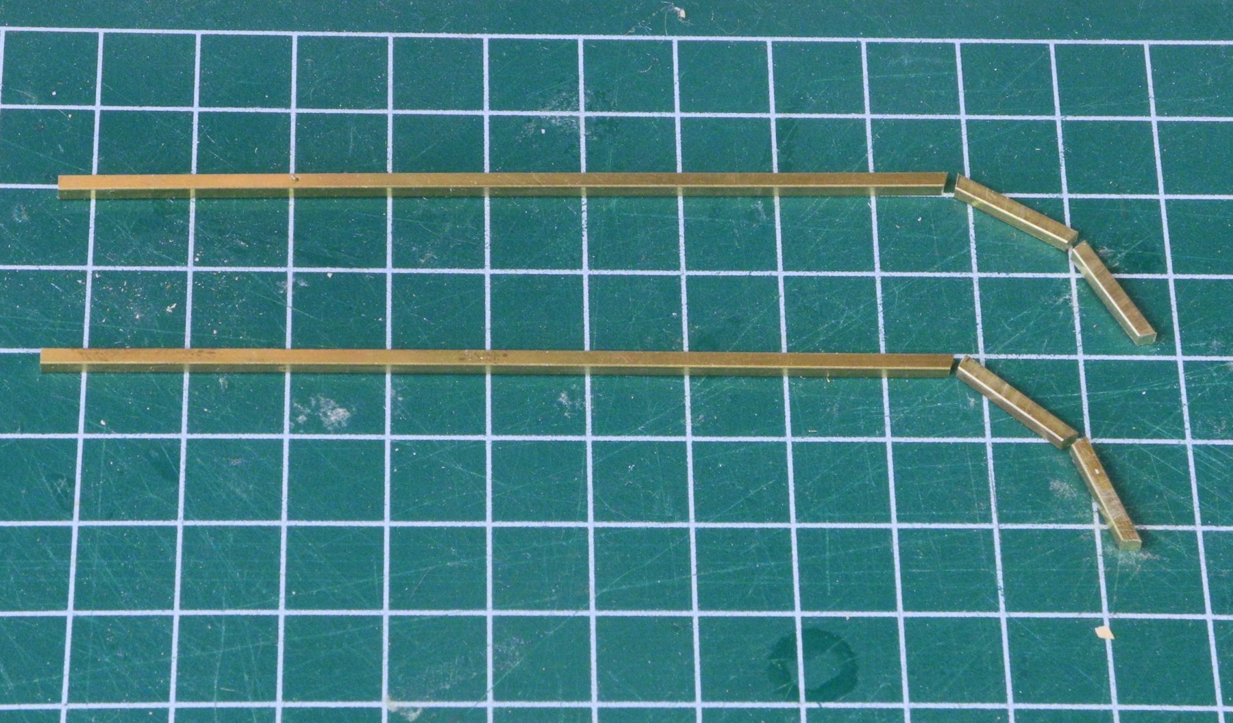
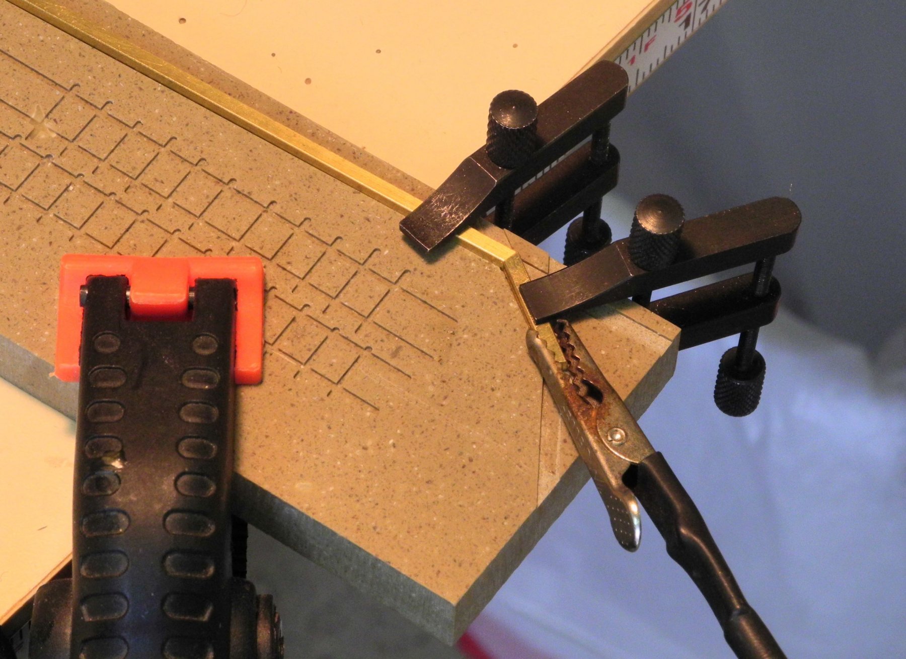
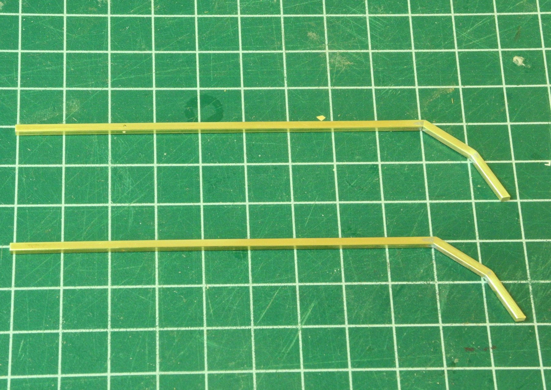
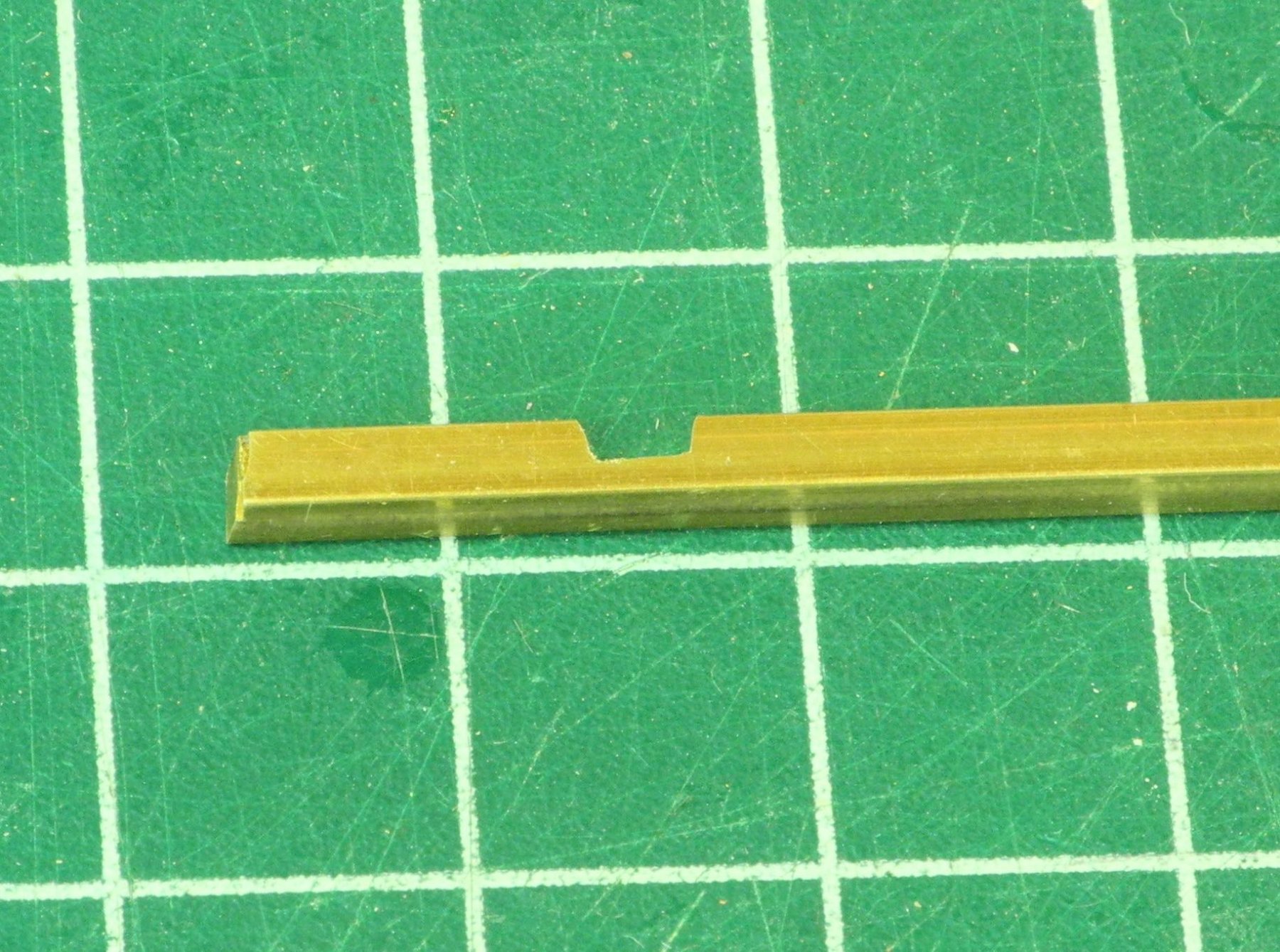
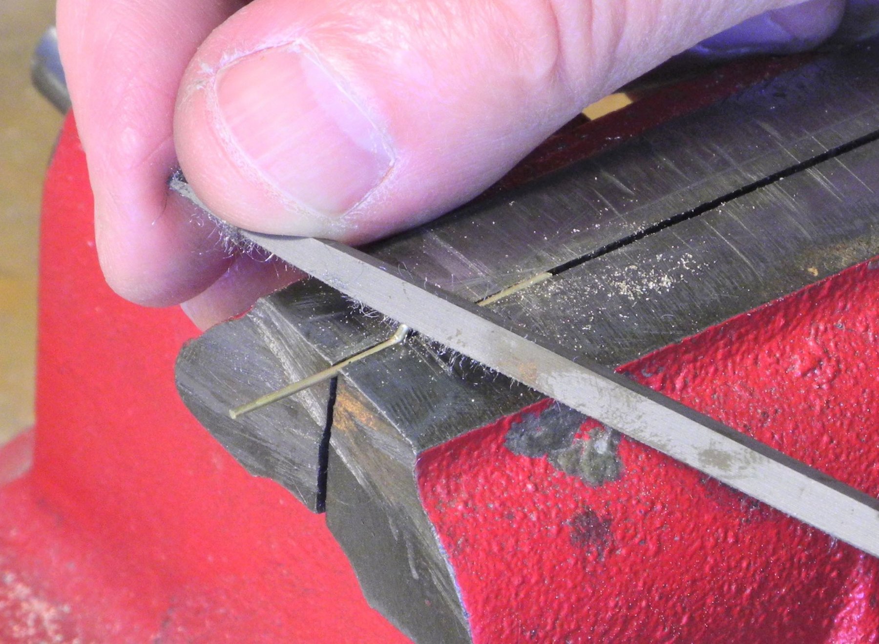
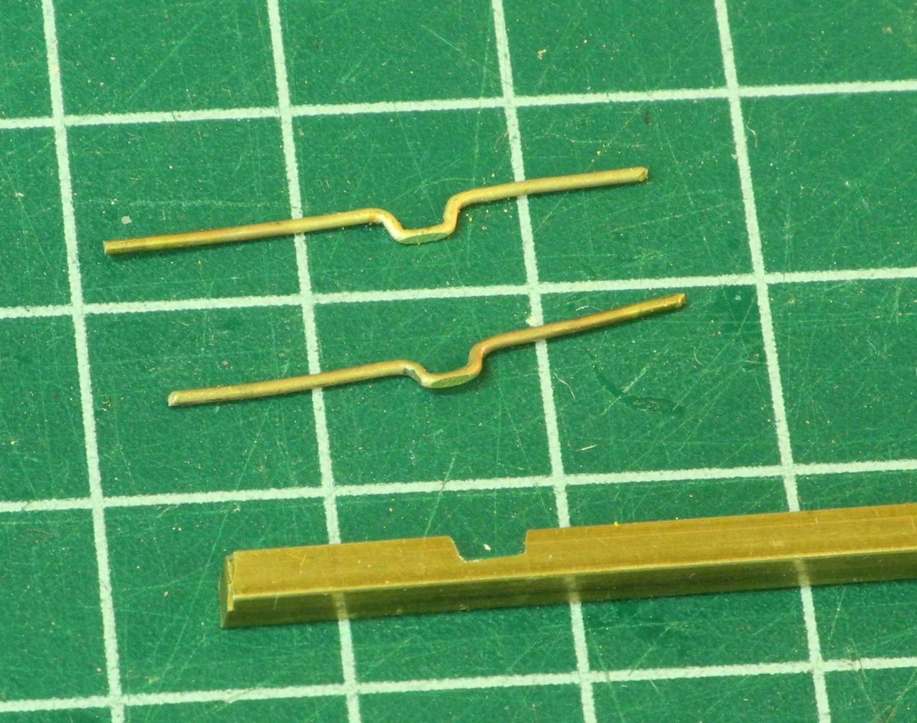
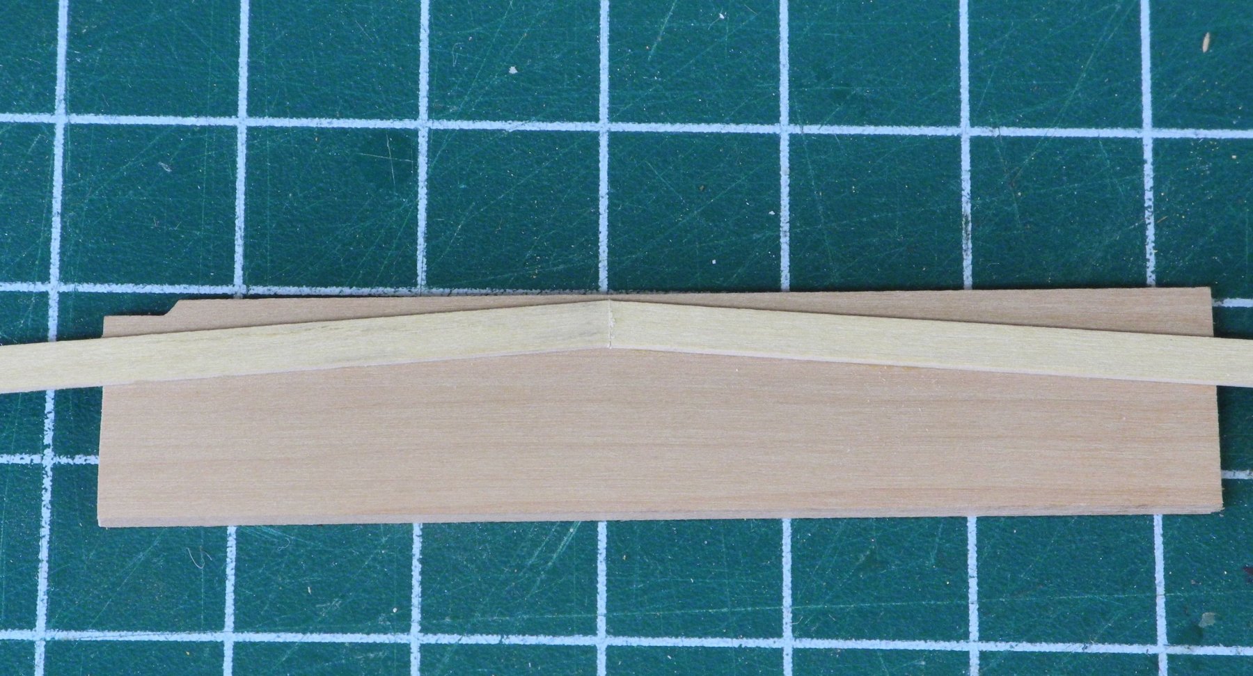
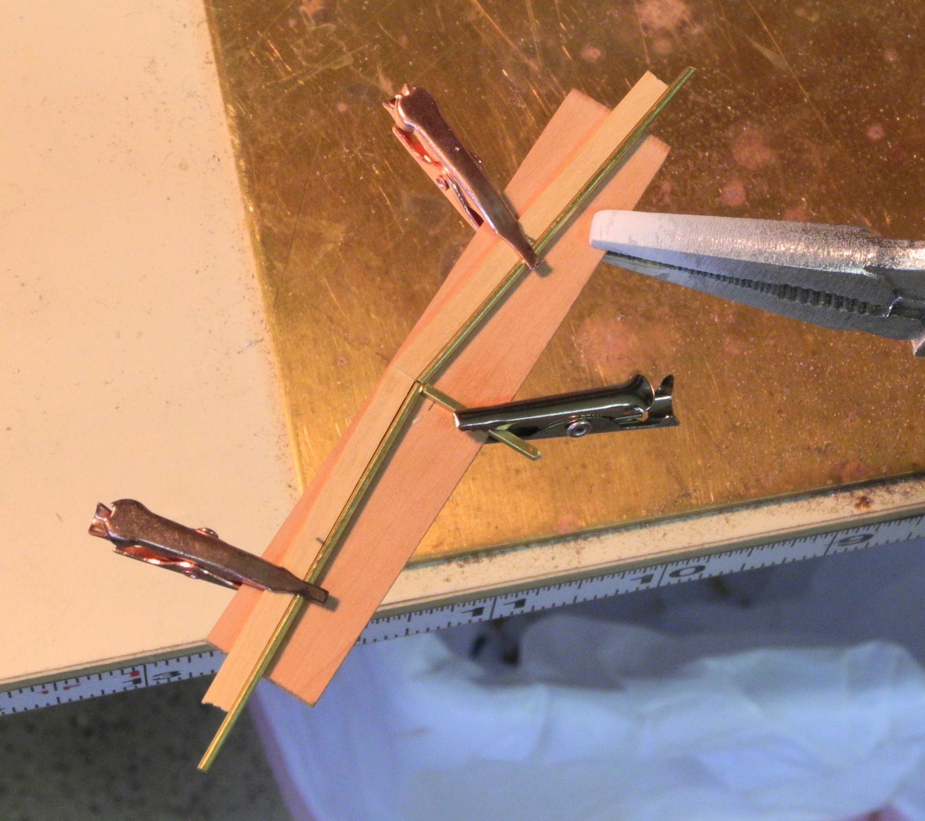
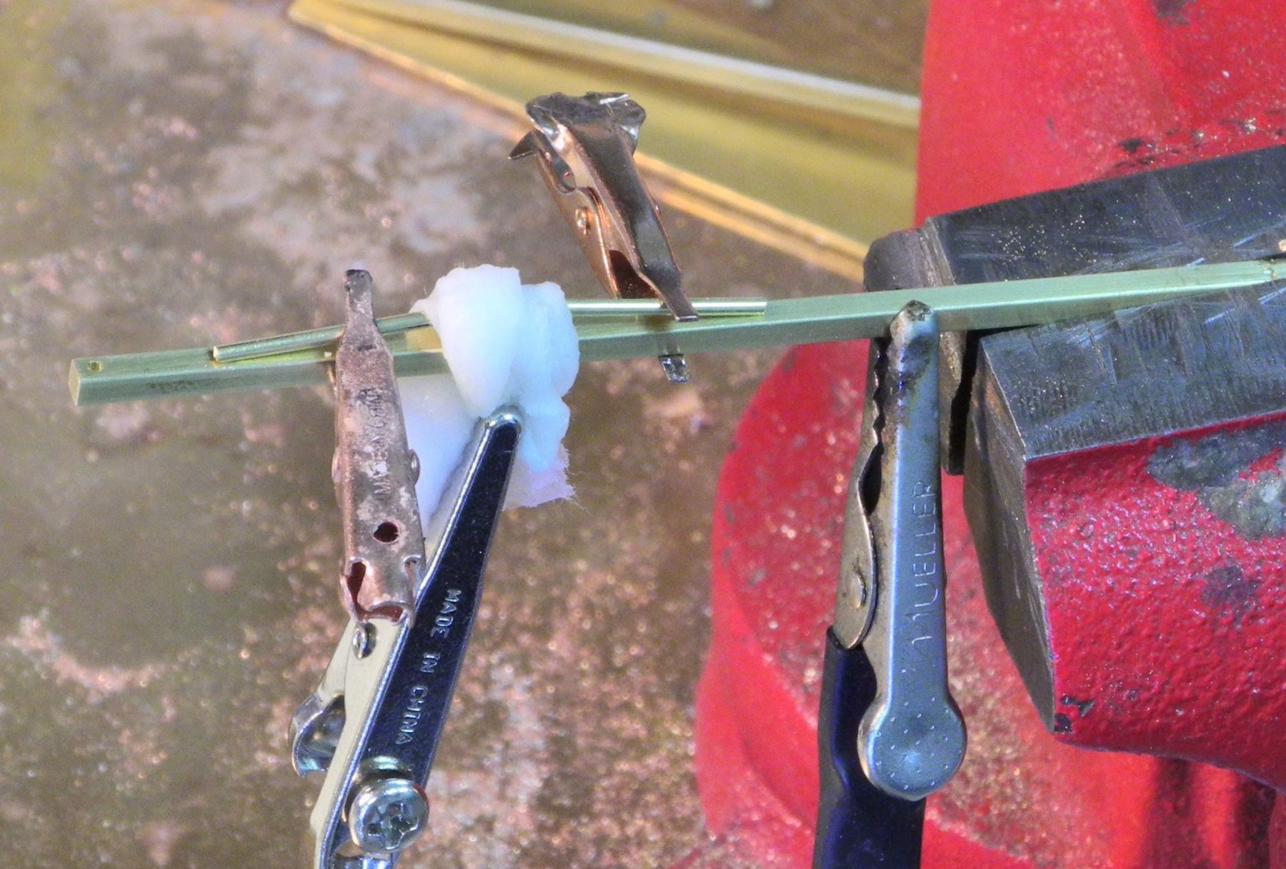
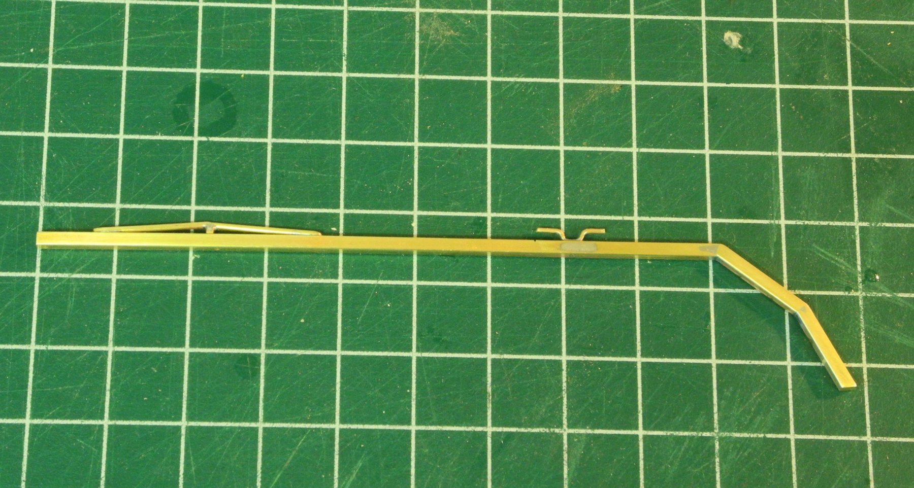
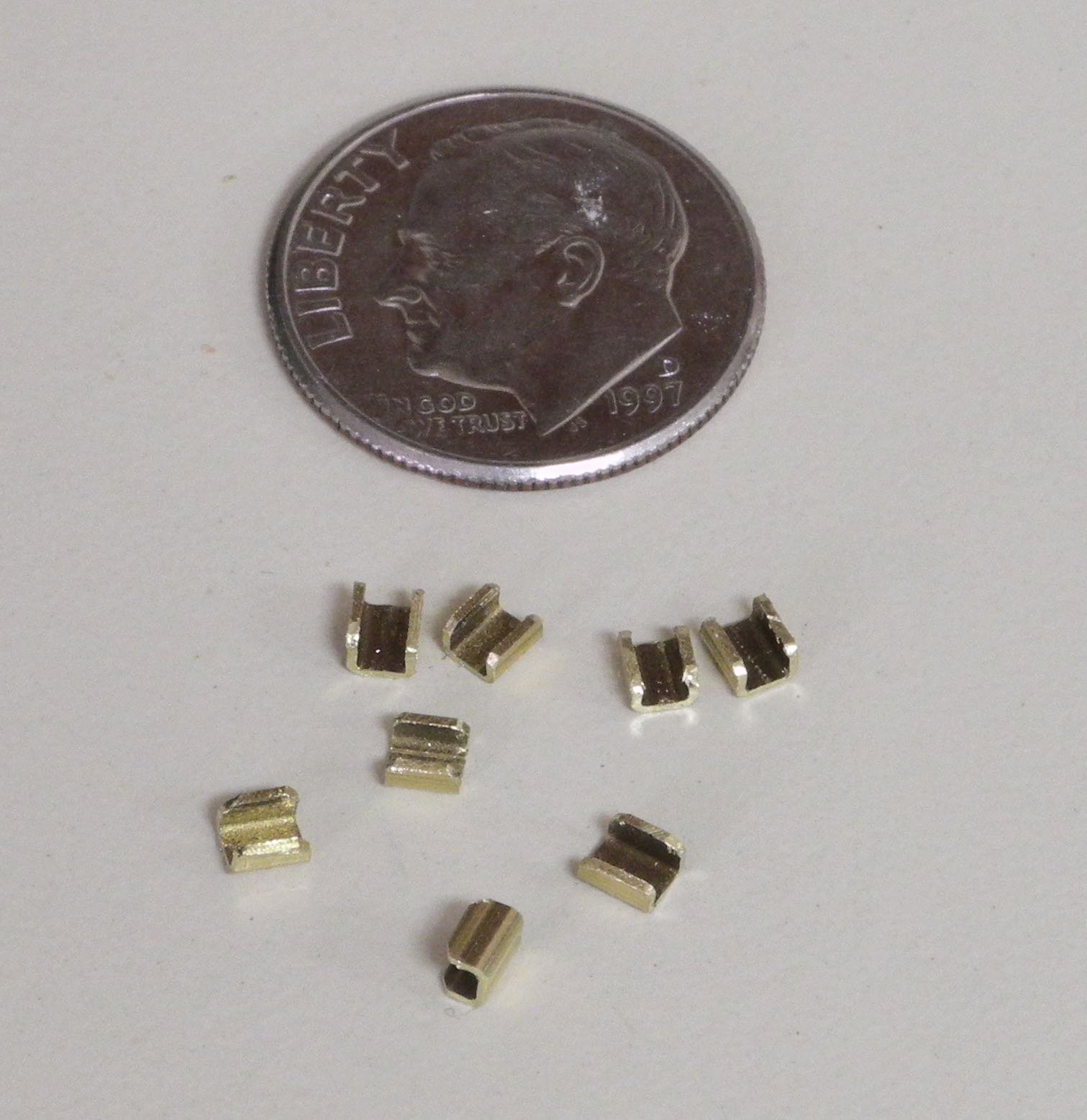
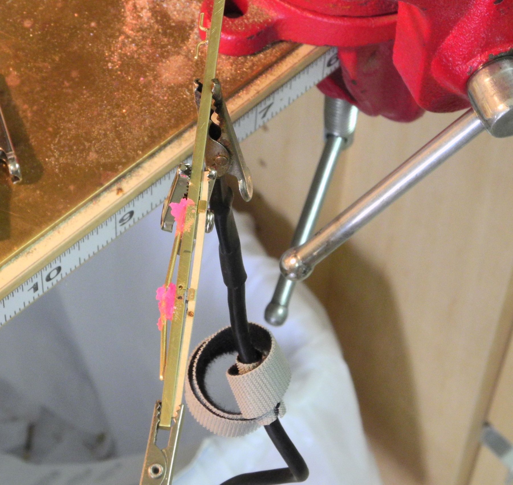
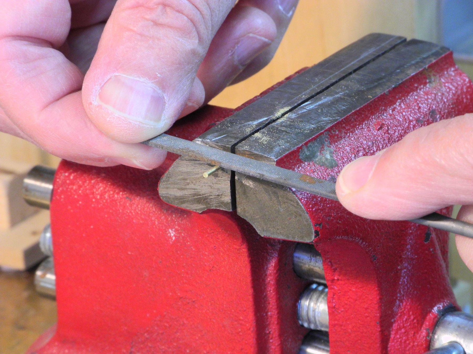
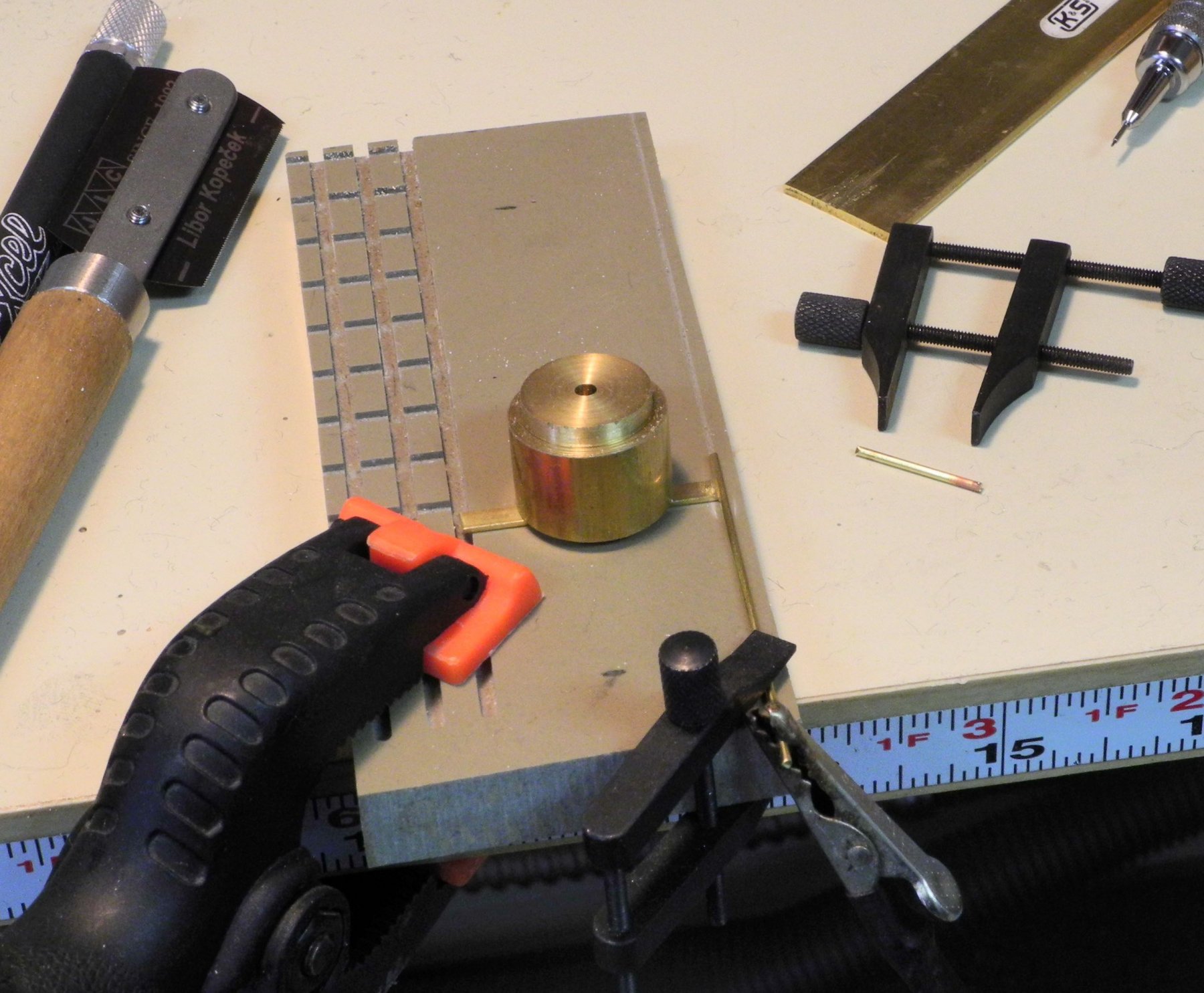
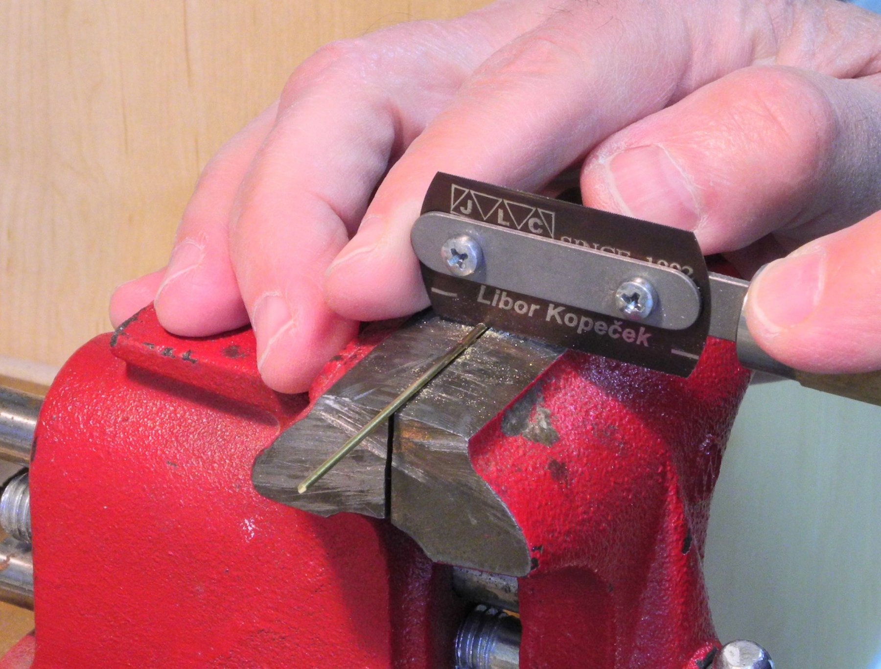
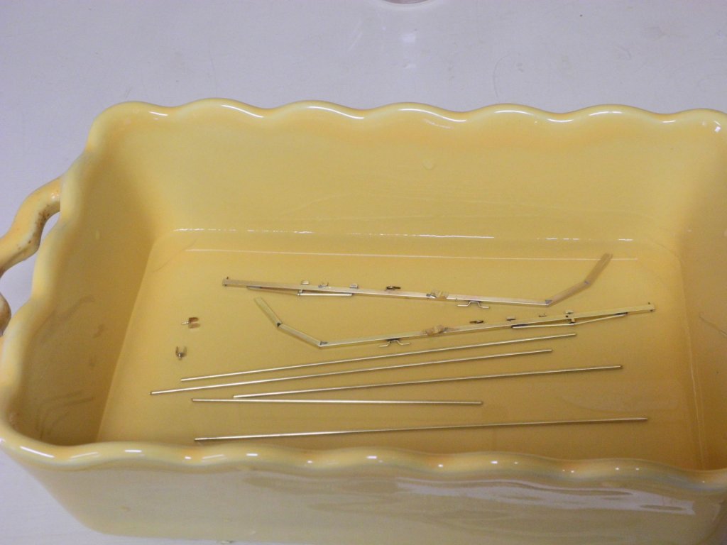
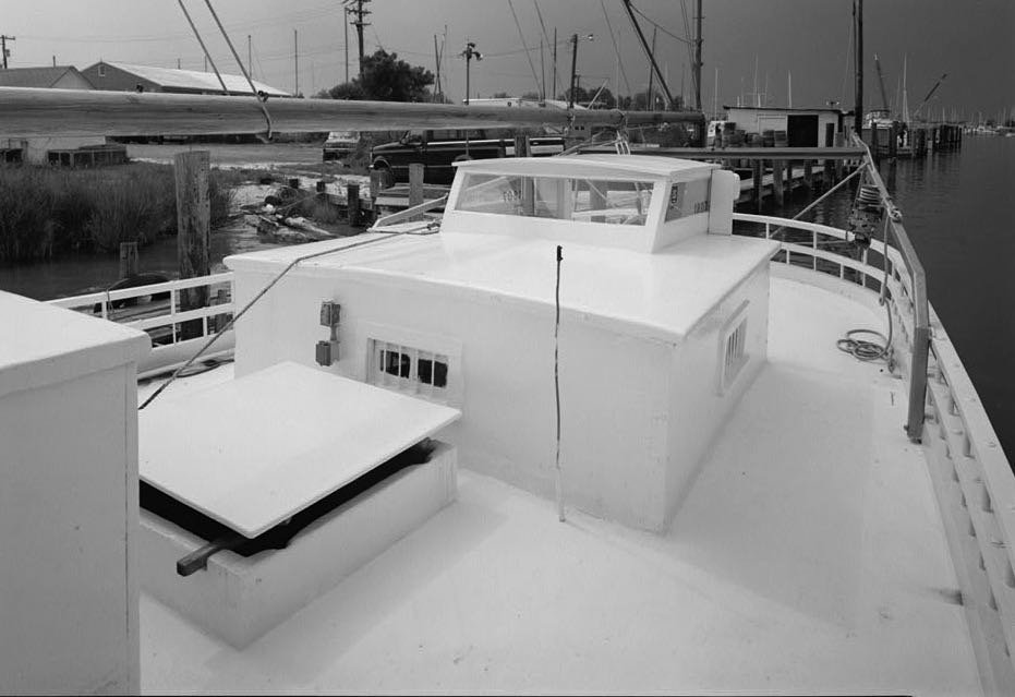
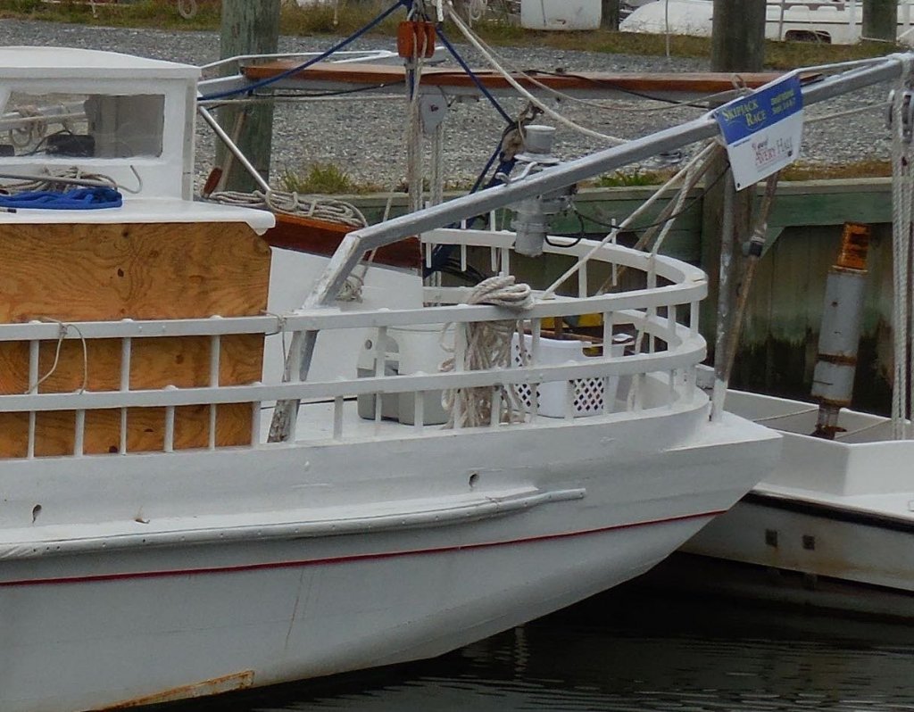
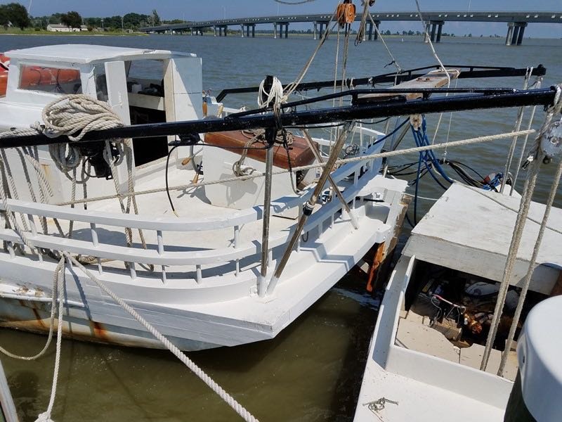
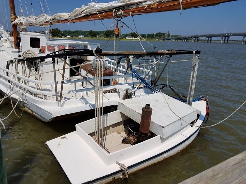
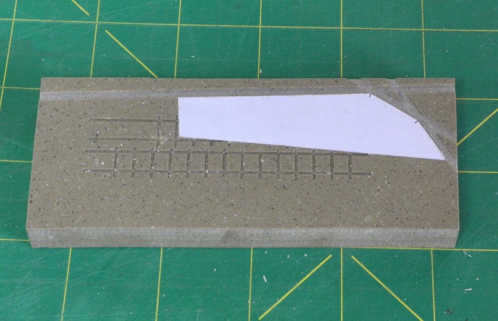
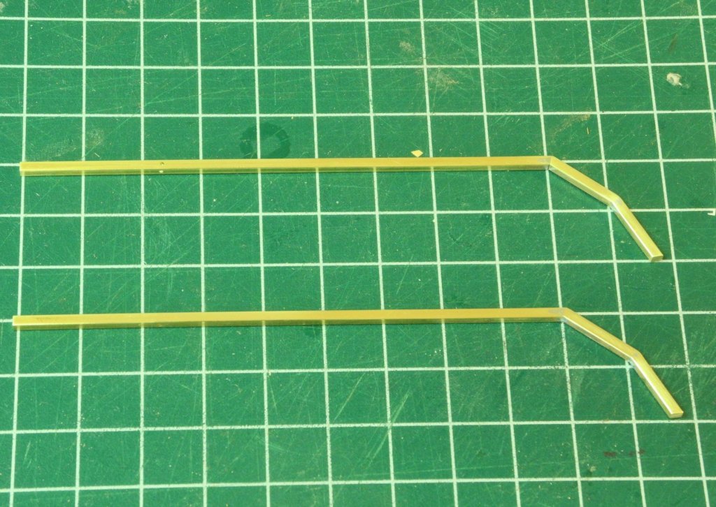
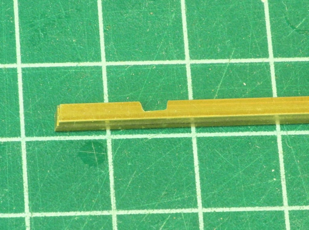
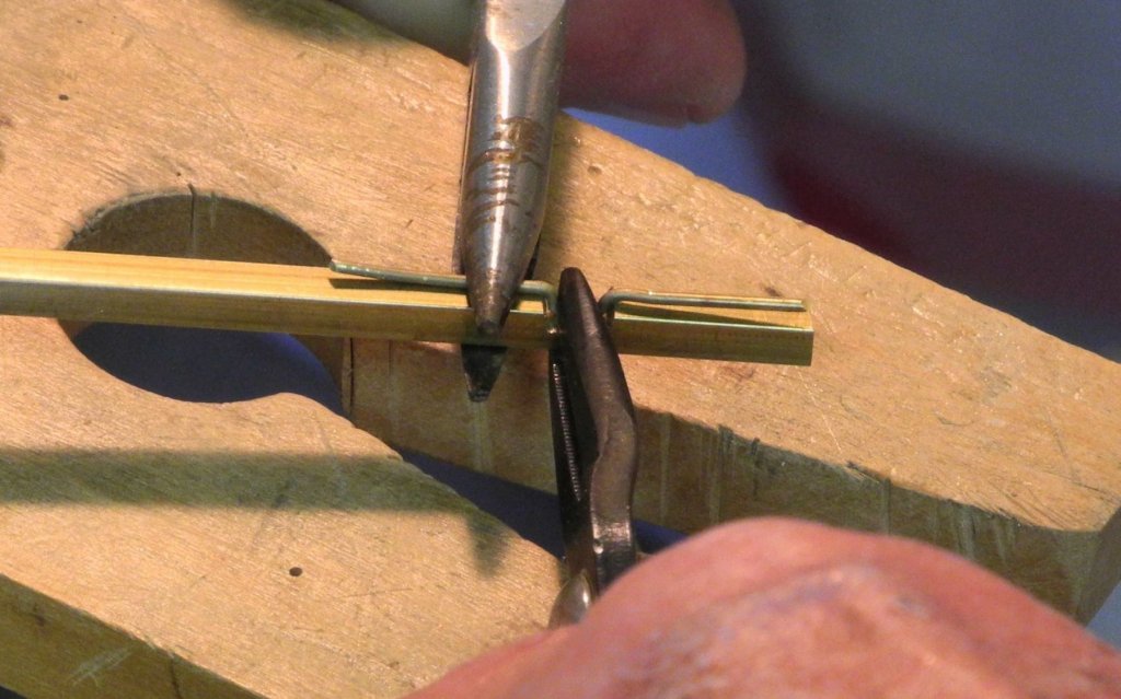
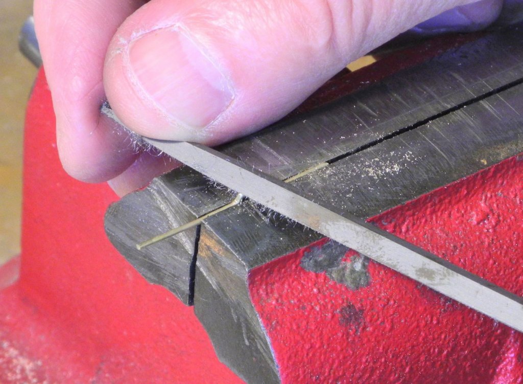
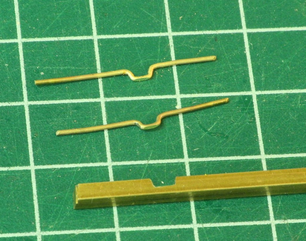
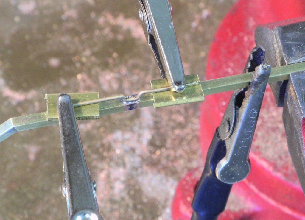
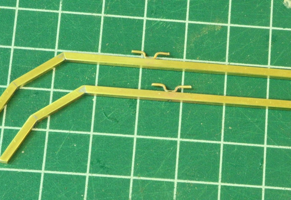
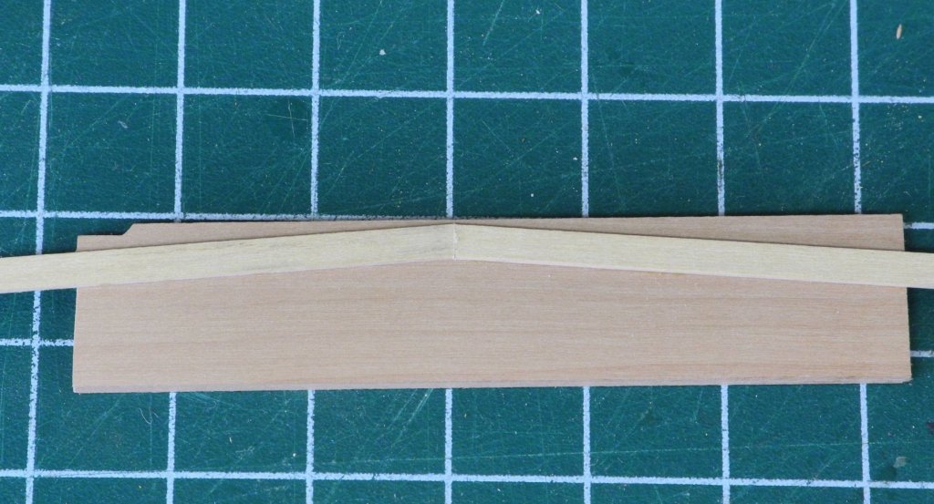
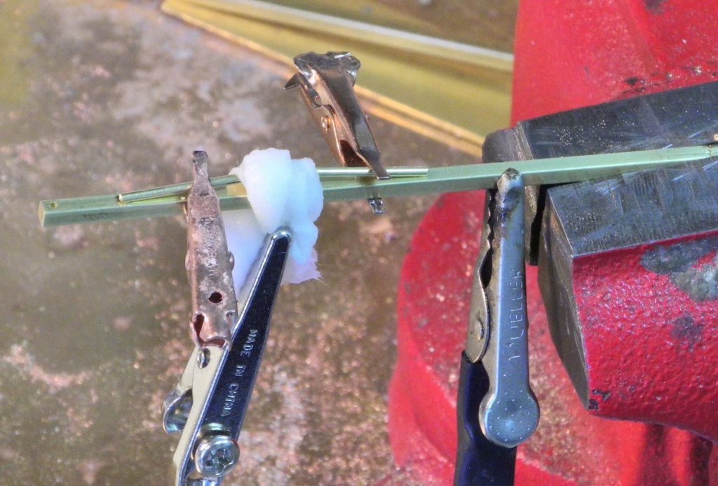
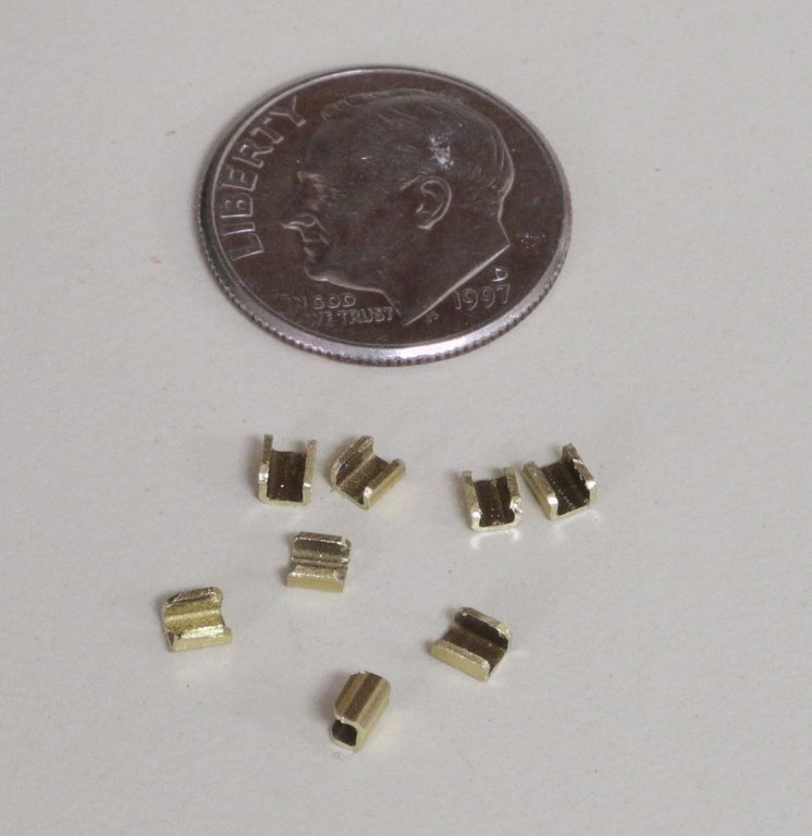
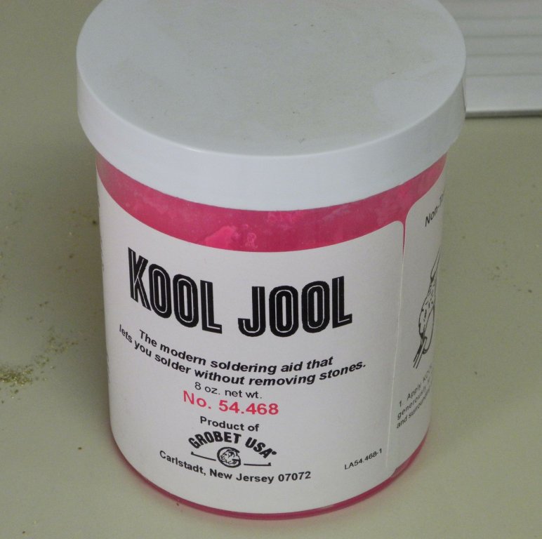
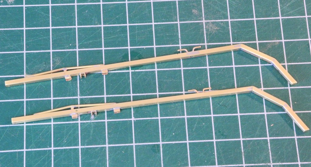
Part 59 – Pushboat Davits Kathryn has a pair of fairly complex davits for carrying the push boat, or yawl boat. The davits are still configured as they were during the HAER survey, but recently the color has changed. When I first saw Kathryn in the fall of 2015 after her recent rebuild, the davits were painted an aluminum color – probably with Rust Oleum paint. Then when I visited in the fall of last year, I found that they had been changed to a glossy black. The HAER drawings show a lot of the details of the davits, and the photos in the book “Working Skipjacks of Deal Island” also show a lot of the details. The following are a few photos of the davit configuration. The first is from the HAER files, taken at the time of the 1995 survey. It doesn’t show a lot of details, but it does indicate that the aluminum color was used back then. The following two photos are from 2015, and show a little more of the details. The forward part of the davit is not straight, but is configured from two separate pieces. There is a cleat arrangement in the forward third of the davit. This cleat is used for tying up when Kathryn is docked. There is an electric winch attached to each davit, aft of the cleats (I still haven’t decided whether I’ll try to duplicate this feature). Aft of the winch there is an angled configuration on the top of the davit, presumably to provide additional strength. The following two photos are from 2017, after the color change. There are two uprights under the angled configuration, one of which is vertical and one is angled towards the push boat. There is another support that runs from approximately the center of the transom out to the davits. Construction of the davits started with the development of a jig that would hold the main pieces at the appropriate angles. The jig was made from Corian, and grooves fitting the dimensions of the davits (3/32 square brass rod on the model) were cut on the milling machine. (Please ignore the lines that look like hatches – they’re from a different jig.) The brass pieces were cut to length and the appropriate angles were shaped using a disk sander. The pieces were held in the jig using miniature machinist clamps. The large clamp on the left is used to hold the jig steady, and the alligator clip on the right is part of the resistance soldering setup. The following photo shows the davit frames after soldering. The cleats needed to be fabricated next. A small jig was made from some square brass rod, to ensure consistency of the shape. 1/32 brass rod was softened by annealing and then was pressed into the jig to achieve the desired shape. The bottom of the cleats was flattened with a file to ensure a solid connection to the davit. Pieces of scrap brass of the proper thickness were used to allow clamping of the cleat without distorting its shape. After soldering, the legs of the cleats were cut to final length and the ends were shaped using a file. The angled brace was made next. A jig was made from wood scraps for each side (two jigs required because the soldering heat might deform or destroy the jig). Two pieces of 3/64” round rod were held in the jig (the ends had been shaped to an angle that allowed the two pieces to fit securely together), and a piece of 3/64” square rod was used as the upright. The following photo shows the jig being held for soldering. The jaws on the right are from a vise grip, mounted in a bench vise and holding the jig. This soldering step formed the triangle shape and the upright as a single piece. The piece was then cut down to the final size, using a rotary tool. After sizing and shaping, the piece was soldered to the davits using the following clamping arrangement. The copper alligator clips are holding the legs of the triangle in place, while the middle alligator clip is keeping a wet piece of paper towel over the previously made solder joint to keep it from loosening. The alligator clip on the far right is from the resistance soldering setup. Each leg of the triangle piece was soldered to the davit using this setup. Sockets are needed on the davits to securely hold the different uprights that will be part of the final installation. These sockets were made from 3/32” square tube that had one side ground off, and cut to 3/32” pieces. Some of these sockets will be added to the davit in the area of existing solder connections. The use of a wet paper towel as above isn’t practical because of the proximity of the socket to an existing solder connection, so a different approach to protecting the existing solder connection was needed. There is a product called ‘Kool Jool’ that I found a while back on a jewelry supply site. Its intended use is to prevent the heat from soldering affecting stones set in a piece of jewelry. I had not previously used the product, but I thought this might be a good solution to the problem. The following photo shows the soldering setup with the Kool Jool protecting the previous connections. A strip of scrap wood was run through the opening in the sockets, and this allowed holding the sockets in place. The product worked very well – there was no loosening of the existing connections. There are still some decisions that need to be made about the davits on the model. Will the electric winches be on the model? Will I add a pulley that can be seen on the underside of the davit? Most importantly, how will the davits be colored to match the aluminum color? So I’m not sure what will follow next – continue work on the davits, or set them aside and work on something else while I work out some issues. Stay tuned to find out!


- 878 replies
-
- 20
-
-
Thanks, Ed. Yeah, I measured the centerboard travel and tried to allow that and more in the tackle movement.
-
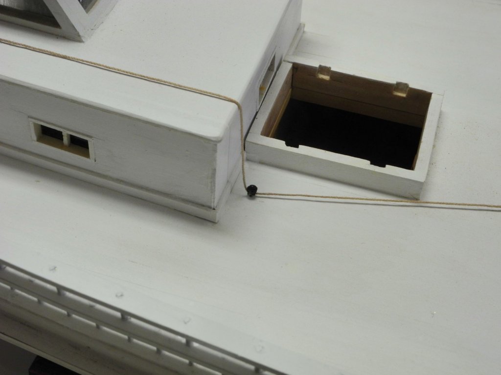
Thanks Popeye. Some skipjacks have a pulley mounted on the side wall of the hatch just in front of the cabin, but Kathryn's aft hatch seems to be too far inboard for that configuration.
-
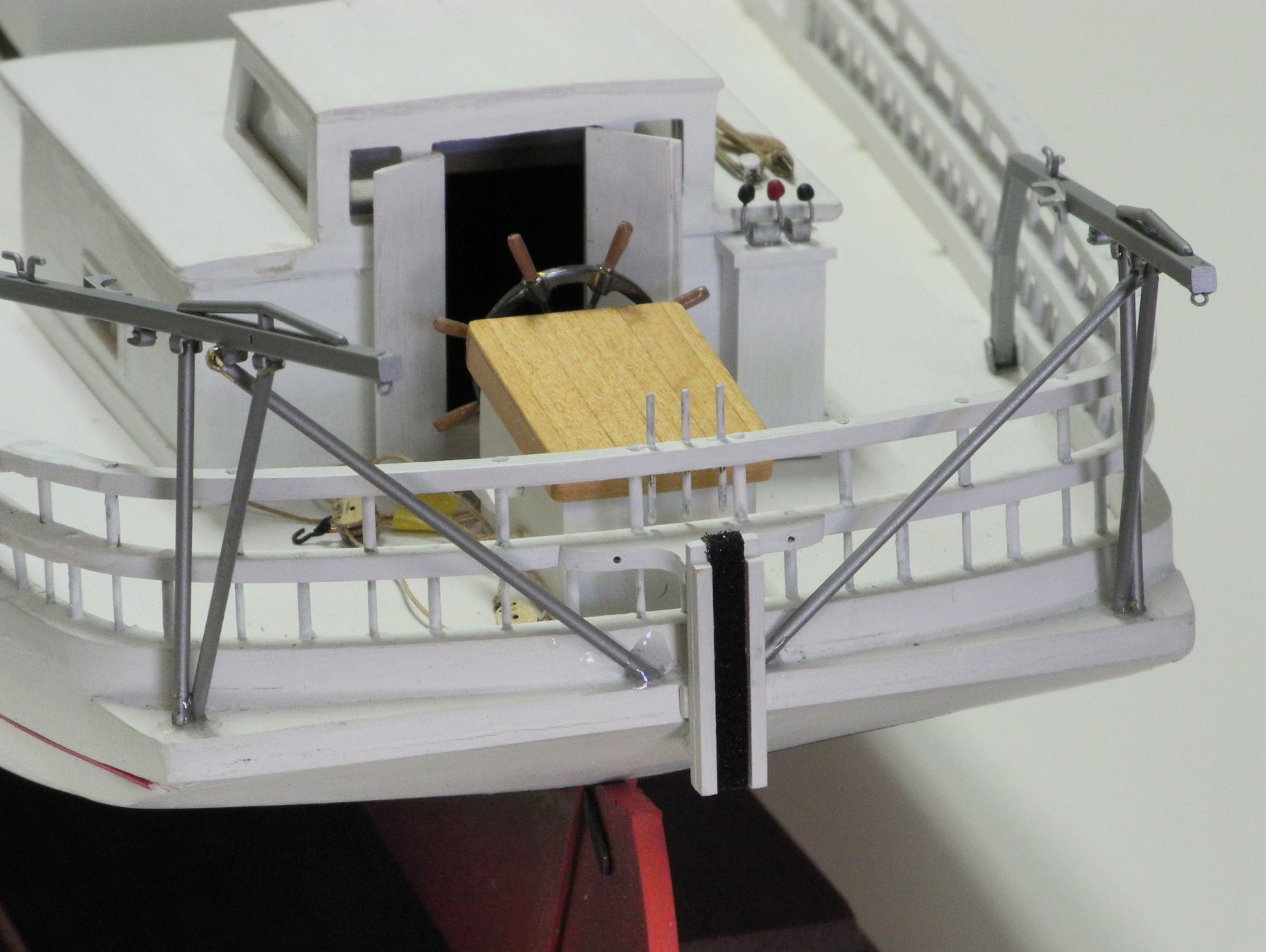
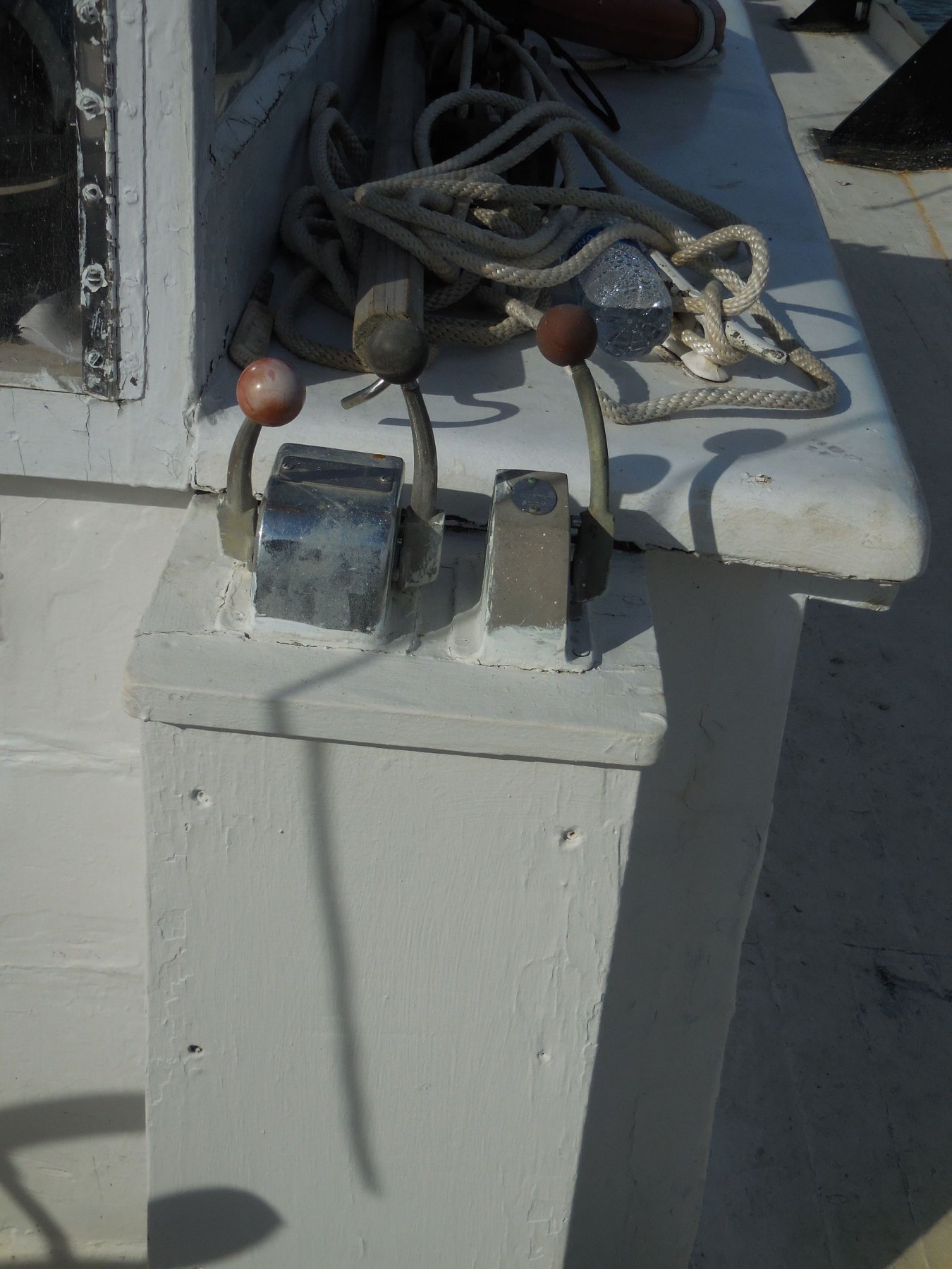
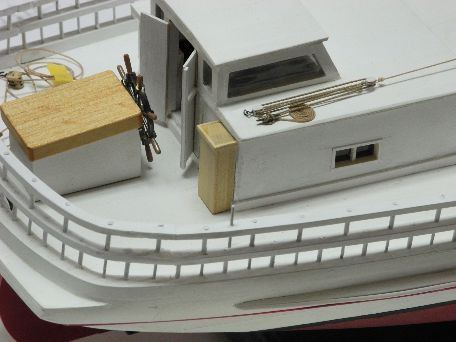
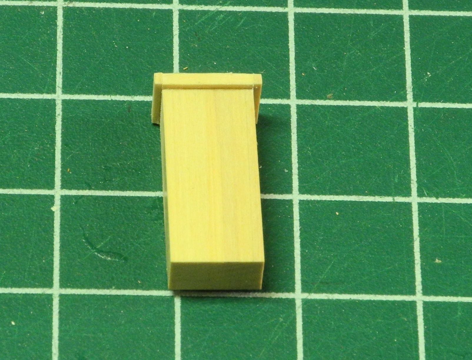
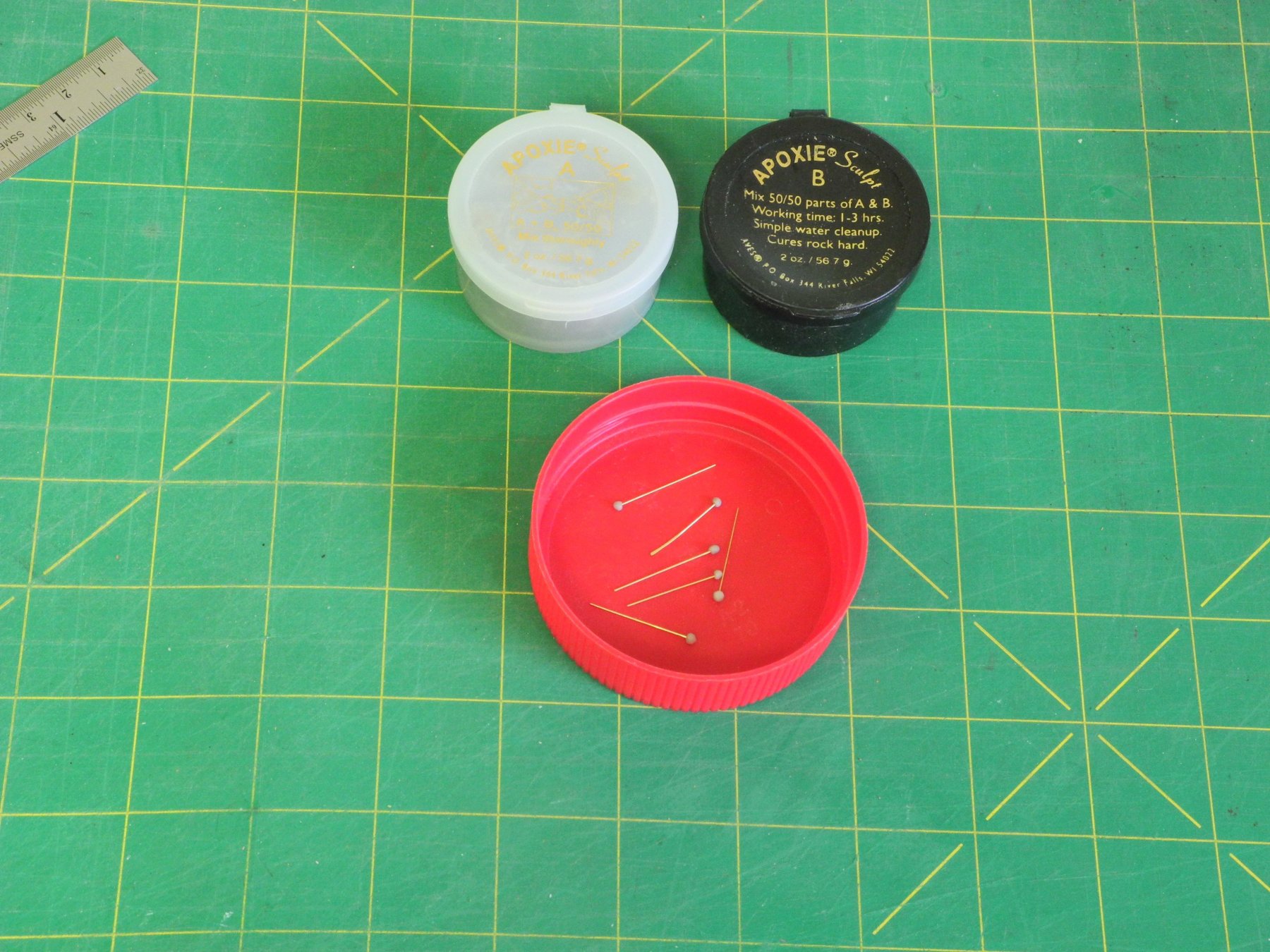
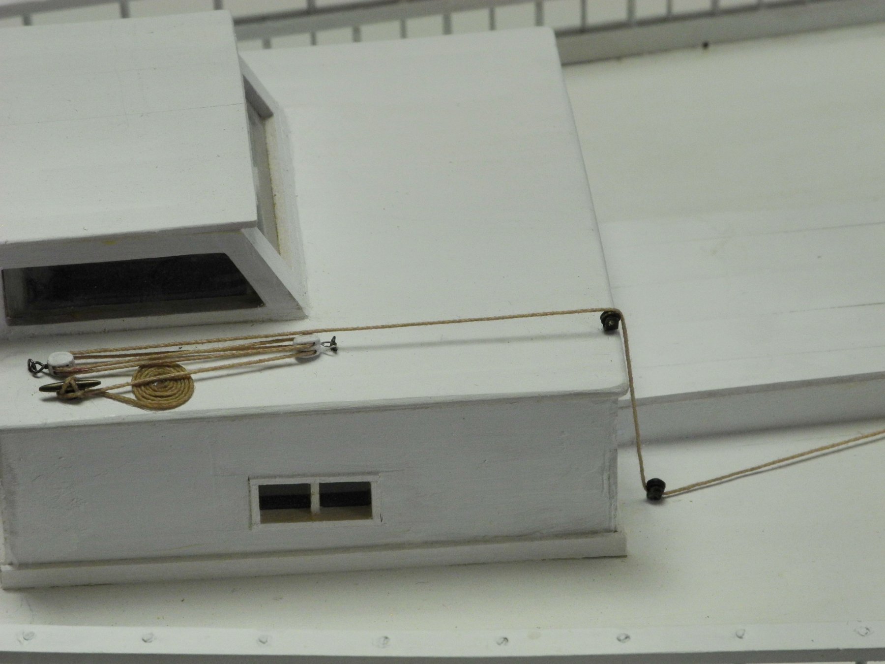
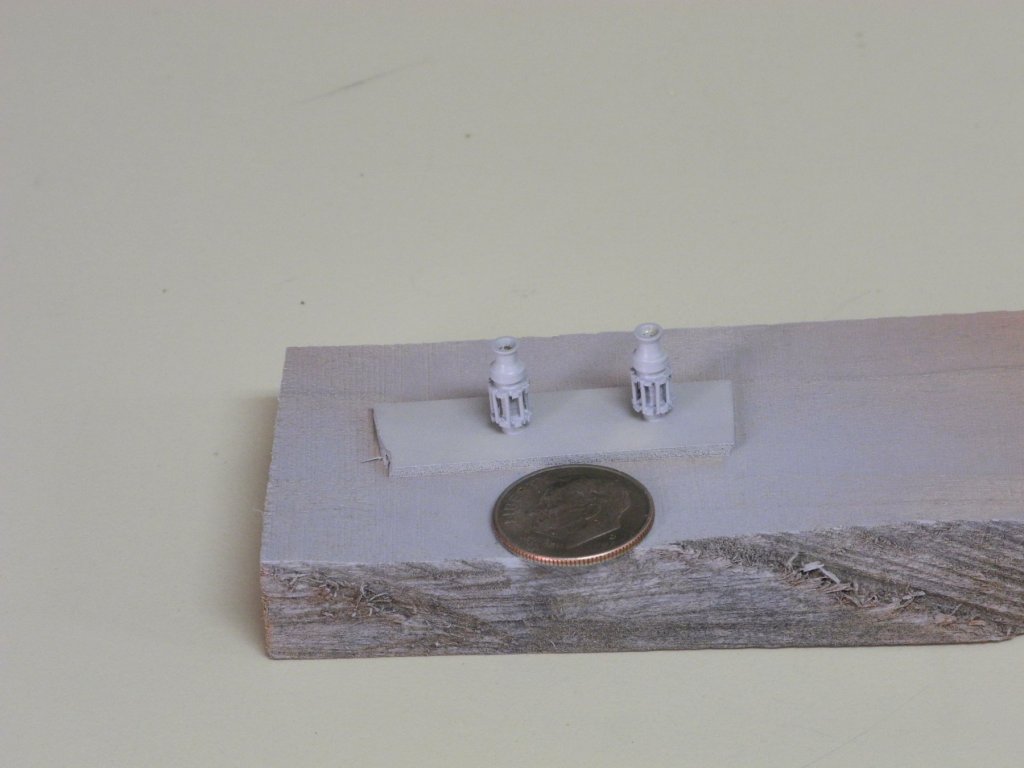
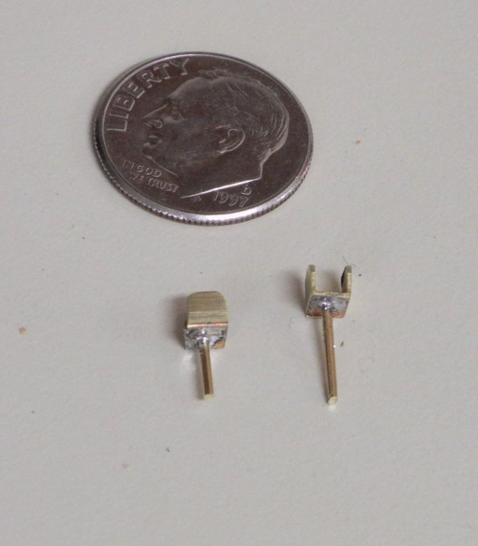
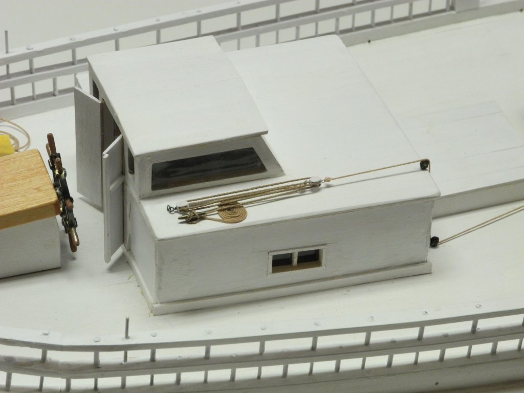
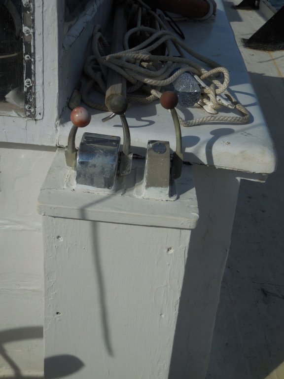
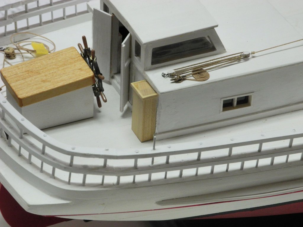
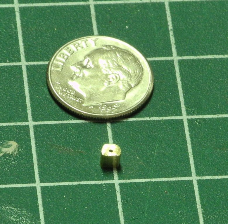
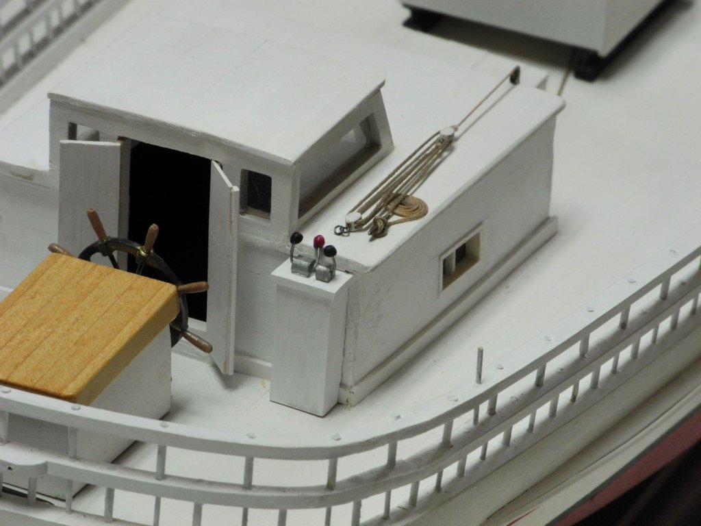
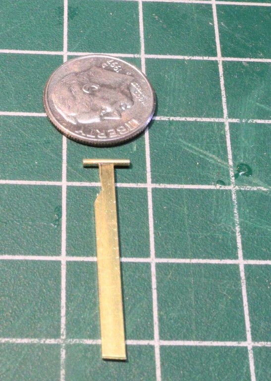
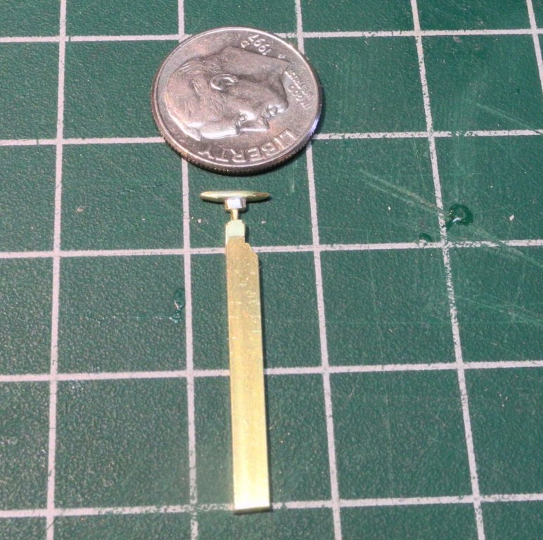
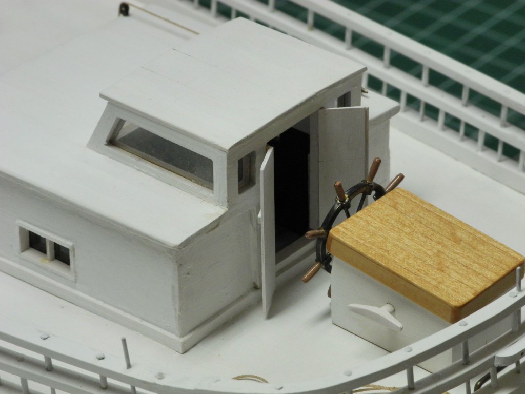
Part 58 – Cabin Exterior Details Cont’d The configuration of the tackle on the Centerboard Hauling Lanyard was incorrect, so the first step was to configure it properly. (Thanks again to Roger for catching this) The remaining exterior detail for the cabin is the set of controls for the push boat, as seen in the following photo. The controls are mounted on a column that is added to the aft wall of the cabin. For the model, the column was made from a solid piece of 3/8” x ¼” hardwood. Moulding, made from 1/16 x 1/32 strip, was added to the top, and a notch was cut into the bottom of the column so that it fit over the cabin base moulding. The control handles were made from .0155 brass rod, and the round knobs were made from Apoxy Sculpt – a self-hardening two-part epoxy modeling putty. The knobs are approximately 1/16", and are as 'round' as I could get them. The two bases for the controls were made from 1/8” brass rod. It was first center-drilled, then the bottom was flattened by milling approximately ¼ of the diameter. The rod was then turned in the vise and approximately 1/10 of the diameter was milled to represent the flat top of the base. The base was painted to match the cabin. The control bases and handles were painted using aluminum color model enamel. The knobs were painted using artists acrylic. In the closeup photo it can be seen that the knobs are not perfectly round, but in normal viewing they give the appearance of round knobs. This completes the work on the exterior cabin detail. Cheers, everyone!


- 878 replies
-
- 19
-
-
Thanks Roger. Yes, the explanation makes a lot of sense. It also prompted me to do a little research on the topic and now I understand it a lot better. I assume the lanyard would be removed from the tackle in the (rare) instances that the centerboard would need to be temporarily removed. In normal operation it appears that the length of lanyard travel would only need to be 3 feet or so and there's enough room on the cabin roof to support that. Thanks again for raising this subject.
-
Thanks Popeye. Yeah, the bit of rigging is cool, but it may be wrong (see my reply to Roger).
-
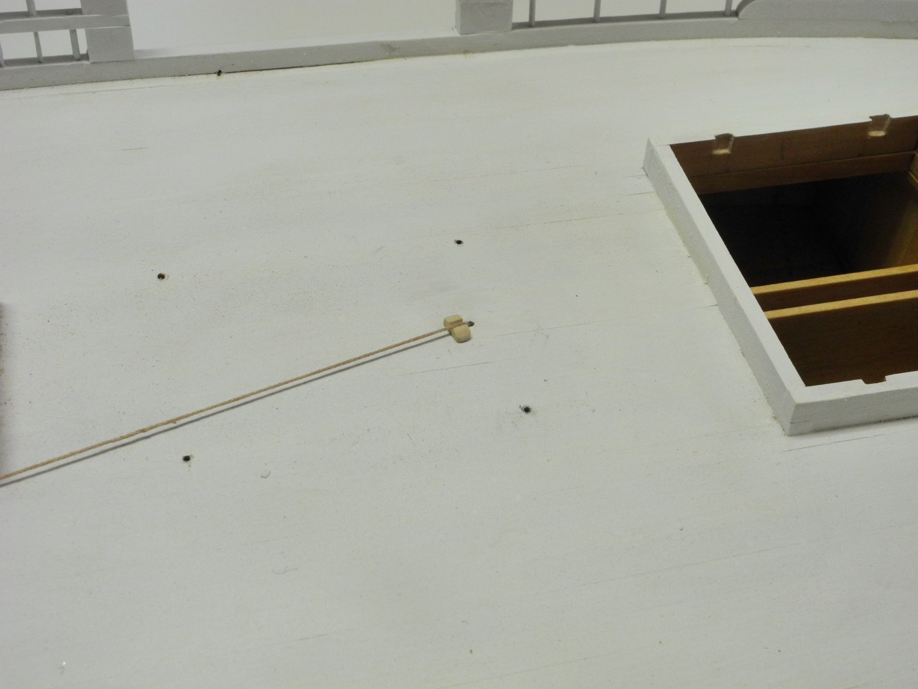
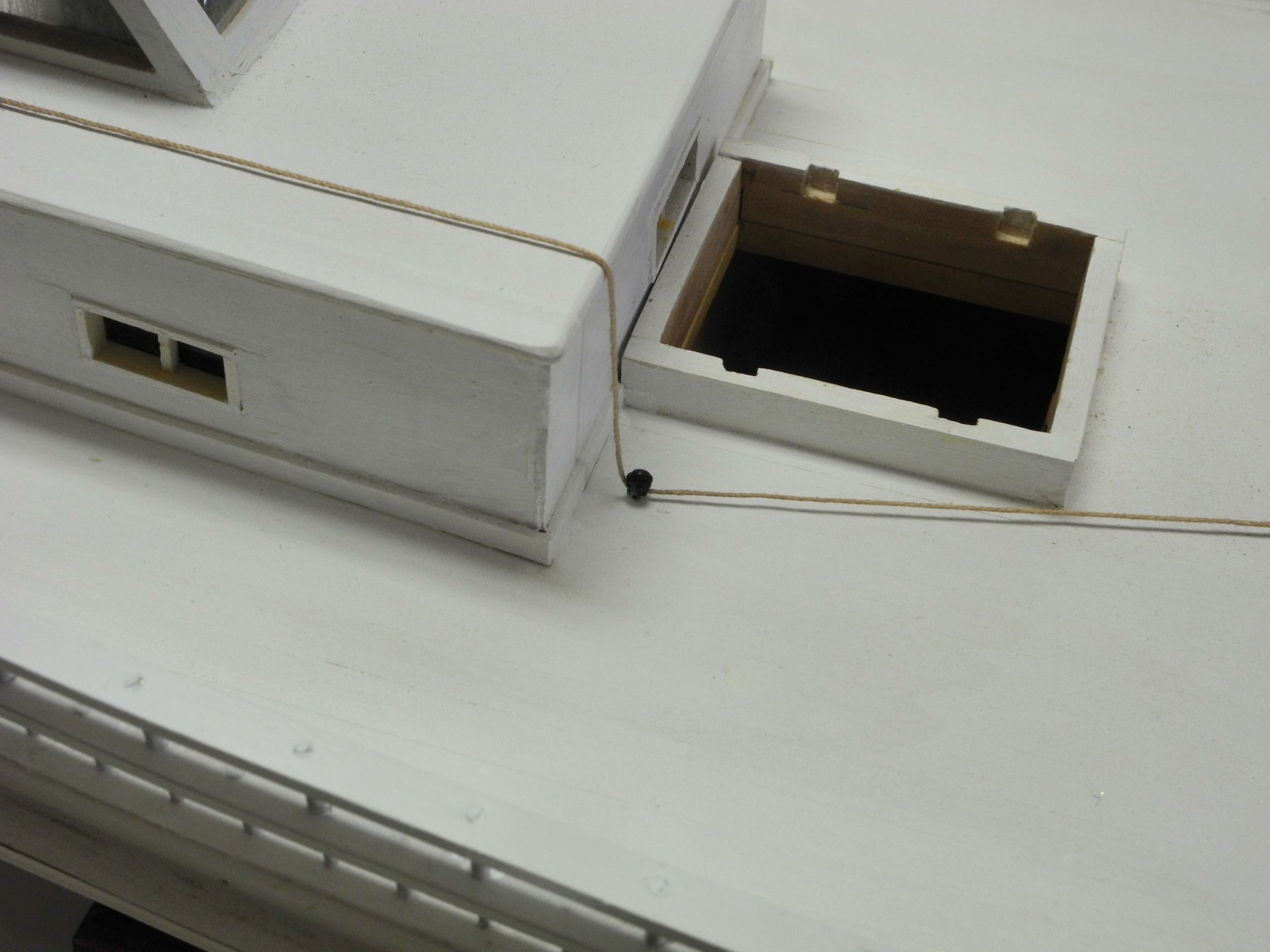
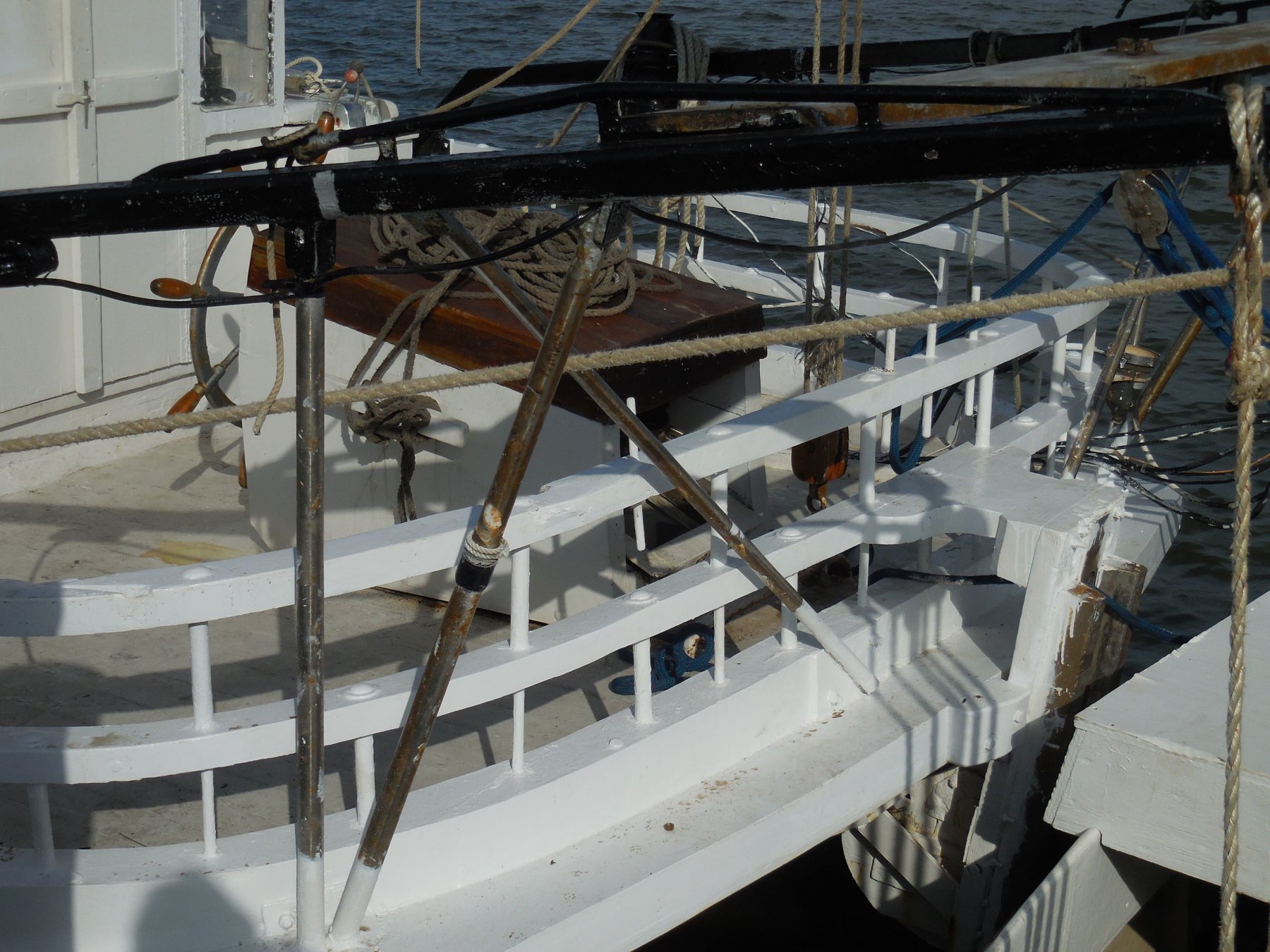
Hi Roger: Thanks for the feedback and the comment on the tackle. I don’t see it as a minor quibble – in fact you raise the same question I originally dealt with. I originally intended to install the tackle as you described, having seen it in the plans for the Willie Bennett. I changed my mind based on some other info, and I probably took the wrong approach, since I’m not all that familiar with the mechanics of tackles. Let me explain why I took the approach that I did: In Chapelle’s book “American Small Sailing Craft” (and in his short pamphlet on Skipjacks) he described how the centerboard would be treated when the boat was pulled out of the water for maintenance. The centerboard would be left in the water, and later (when the maintenance was completed and the boat was back in the water), the centerboard would be brought up into its case using the lanyard and a fore-end line. It seems to me that the length of travel of the lanyard tackle would be limited to the length of the cabin roof that it sits on, so I had a hard time visualizing this operation. In addition, the lanyard travels under a pulley normally located on the deck or on the side of the aft hatch, as in the case of the Willie Bennett. I found the following photo of the Kathryn’s deck pulley for the lanyard in the book “Working Skipjacks of Deal Island”. Since the lanyard runs under the pulley, I saw this as an additional limitation to how far the tackle could move. I was also confused by the length of the coil shown in the HAER photo I included in my post. It seemed to me that if the lanyard was spliced to the forward block there would be no need for the length of line shown in the coil. Again, I’m not very knowledgeable on the mechanics of these tackles, so I probably was in error. If you, or other readers, could help me understand how the issues I mention above would be addressed with the alternate tackle arrangement then I probably would re-do the tackle to make it more correct. Thanks again for your feedback – to me, this is the real value of this forum. Discussions like this are a valuable part of the learning process.
-
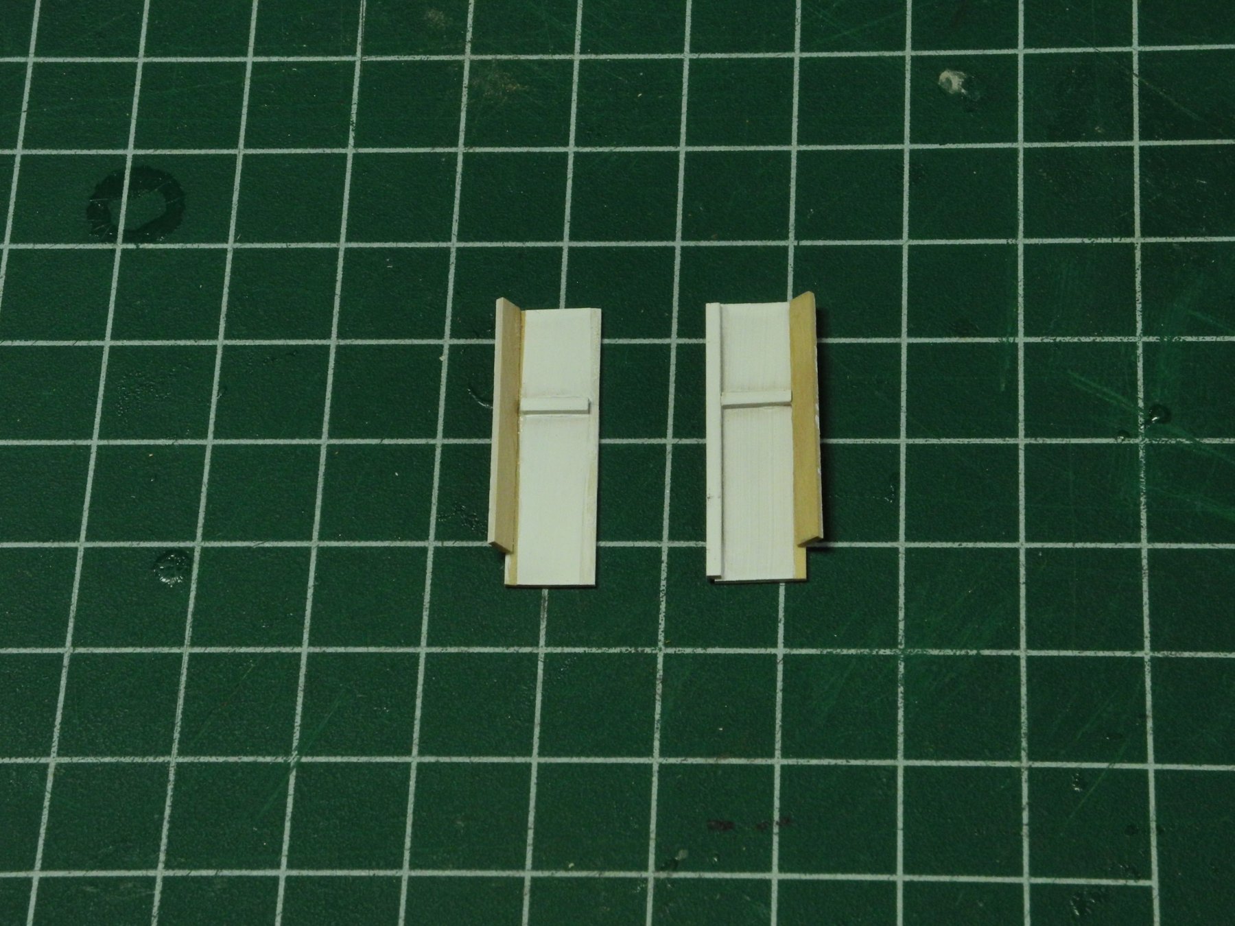
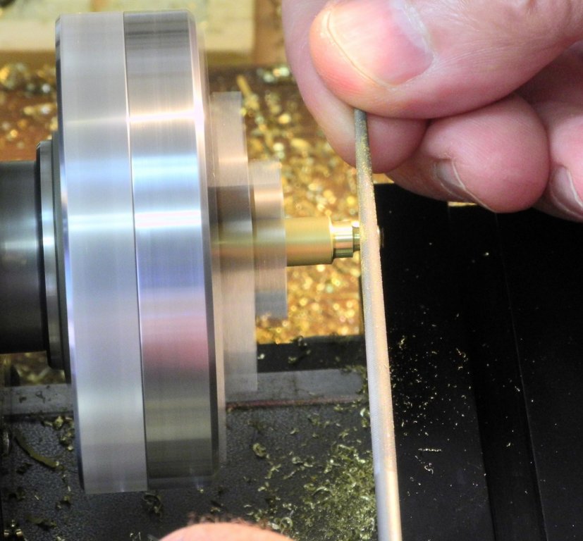
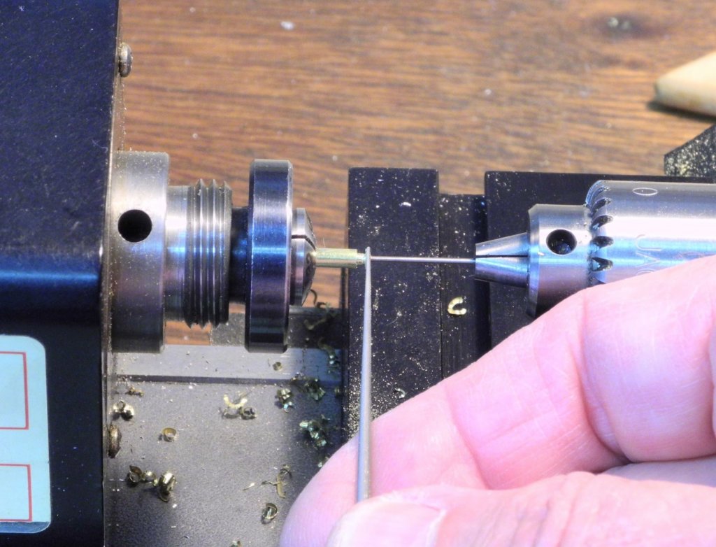
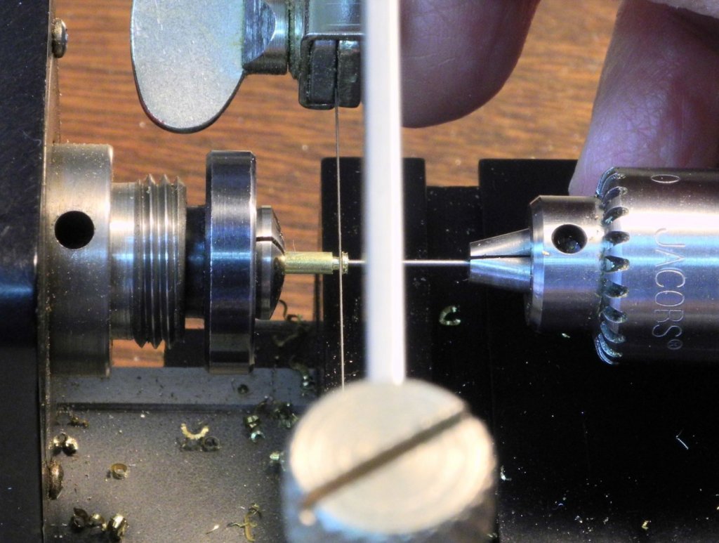
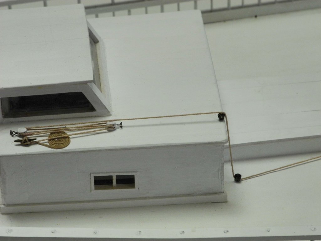
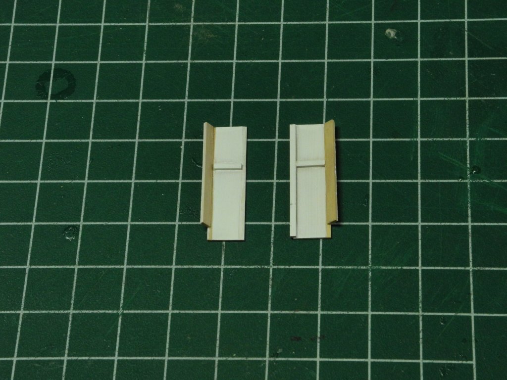
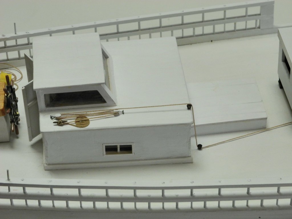
Part 57 – Cabin Exterior Details My original intent was to construct Kathryn’s cabin so that the roof would be removable, allowing the interior of the cabin to be easily seen. After a lot of thought I decided against this for the following reasons: 1. The boom will be very close to the cabin roof, and there would be a real danger of disturbing the boom if the cabin roof was not very carefully moved. 2. Each cabin door consists of two parts, which allows the doors to be opened for the doghouse while leaving the lower parts closed. Constructing these doors as two separate parts would make a very delicate part that could be damaged when the roof was removed. 3. The Centerboard Hauling Lanyard is run over the main roof of the cabin, with pulleys, tackles, and a cleat for securing the lanyard. Leaving the roof removable would eliminate this interesting detail. The following HAER photo shows some of the detail of the Centerboard Hauling Lanyard. Also note the controls for the Push Boat just behind the lanyard. There are two metal cleats on Kathryn: one that secures the hauling lanyard on the cabin roof, and one that is mounted on top of the bowsprit to secure the jib downhaul. The other cleats are wooden cleats. The metal cleats for the model were made from 3/64 brass rod and 1/8 x 1/32 brass strip. The brass rod was flattened on one side using a file. This would allow the strip to closely mate with the rod. A light groove was milled in a piece of Corian to hold the rod so that the strip could be centered on the rod for soldering. The rod was then cut to the appropriate length with a razor saw. These metal cleats are 8” long (1/4” on the model). The strip was narrowed its final width, using a file and a rotary tool. The cleat was then ground to its final shape using a rotary tool with diamond cutters, and was polished using emery cloth. The post for mounting the cleat was also cut into the strip. The cleat was then blackened using a well-diluted (5:1) mixture of the JAX Flemish Black, giving a steel-like color. The following photo shows the jib downhaul cleat in place on the bowsprit. There are two open pulleys that service the Centerboard Hauling Lanyard. One is on the deck, with the lanyard running below the sheave. The other is on the cabin roof, with the lanyard running over the sheave. The sheaves on the model were made from 3/32” brass rod, which would equate to 3” diameter. The rod was bored out for the axle using a center drill followed by a HHS drill. The width of the sheave on the model is .020. A parting tool was used to cut partway through the rod so that this width was set off. A very small round escapement file was then used to form the groove in the sheave, by carefully filing the shape as the lathe turned at a relatively slow speed. The sheave was then parted off using a jewelers saw while the lathe was turned by hand. A HHS drill bit, reversed in the tailstock, was used to prevent the sheave from coming loose when it was parted (it would probably never be found again if it left of its own accord!). The body of the pulley was made from a 1/16 strip of .010 brass sheet that had been cut using a paper cutter. The strip was bent around a 1/32” thick piece of brass strip to get the appropriate shape, and was then bent around a sacrificial piece of wood for drilling. A mounting post was soldered to the hole drilled at its base. The shape of the body was then finished using a rotary tool and a diamond cylinder. The sheave was mounted in the body and soldered on one side of the axle. The pulley was then cleaned up using files and emery paper. The Centerboard Hauling Lanyard comes out of the deck under the dredge winder, with a wooden fairlead in place to keep the lanyard from fraying on the edge of the hole in the deck plank. The lanyard then runs under a pulley mounted at deck level just forward of the cabin. The lanyard then runs over a pulley on the cabin roof, through a double-block tackle, and is tied off to a cleat. The cabin doors are fairly plain, and seem to be made mostly from plywood. The hinges on the real Kathryn are piano hinges painted to match the doors, so they are virtually invisible. The outside of the doors have some strips to provide protection from weather for the separation between the upper and lower parts of each door, between the two doors when they are closed. The interior of the doors are plain and flat. I wanted to leave the doors open so at least some of the cabin details could be seen, but I wasn’t thrilled with having plain flat doors being the only thing showing. In addition, if the doors were fully opened then the rear windows of the doghouse would be blocked. To resolve these issues I decided to have the doors propped partially open. Thin pieces of wood strip were shaped so that one edge was angled. These strips were glued to the doors at that angled edge and served as a door jam. The door jams were glued to the inside of the door frames. So now the cabin exterior details are completed. The only thing left on the cabin is to fabricate the column that contains the controls for the Push Boat. This will probably be the subject of the next post. Cheers everyone!


- 878 replies
-
- 21
-
-
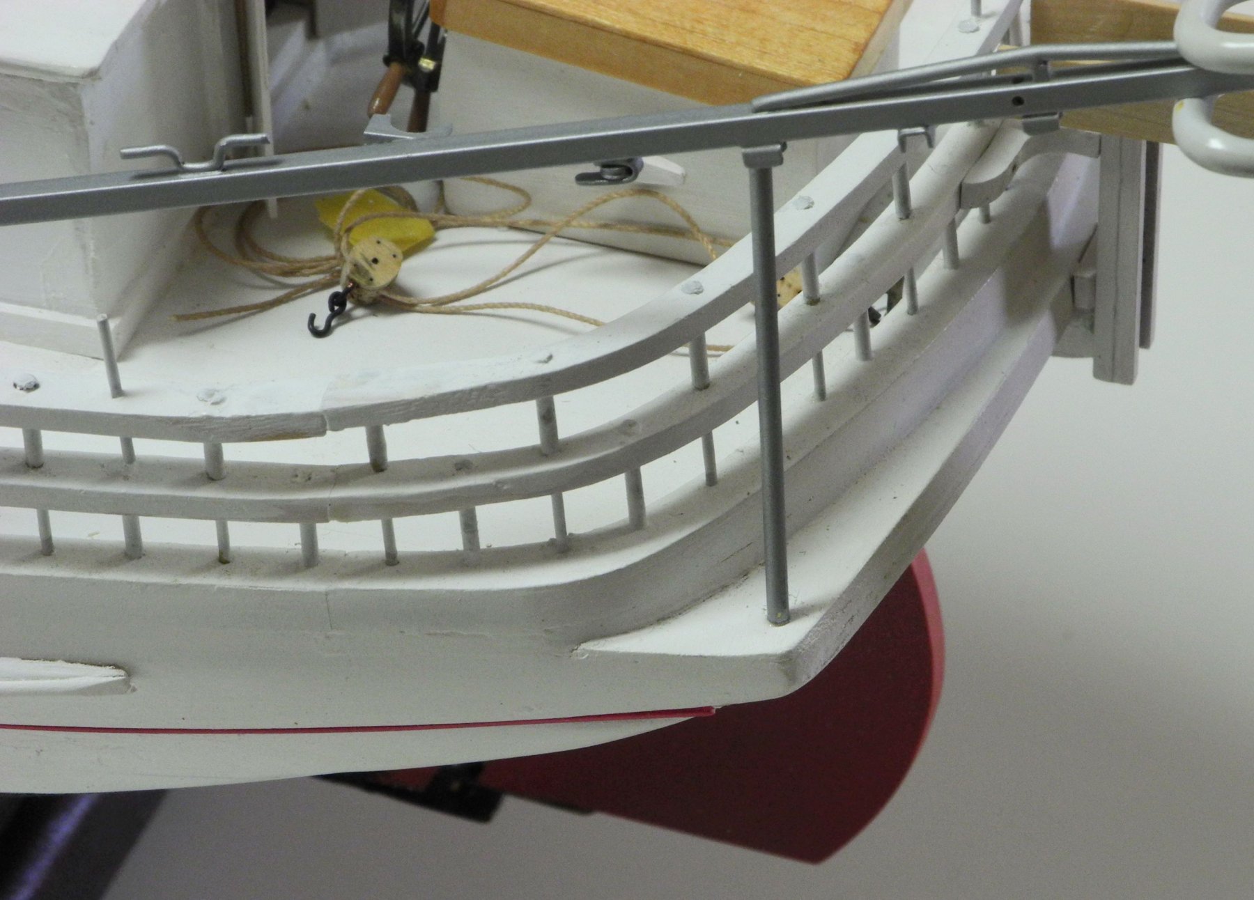
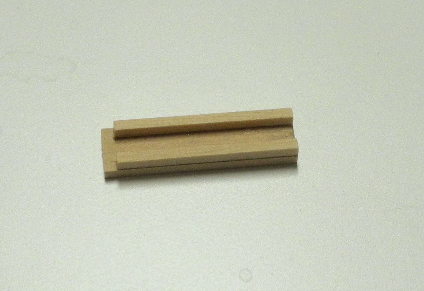
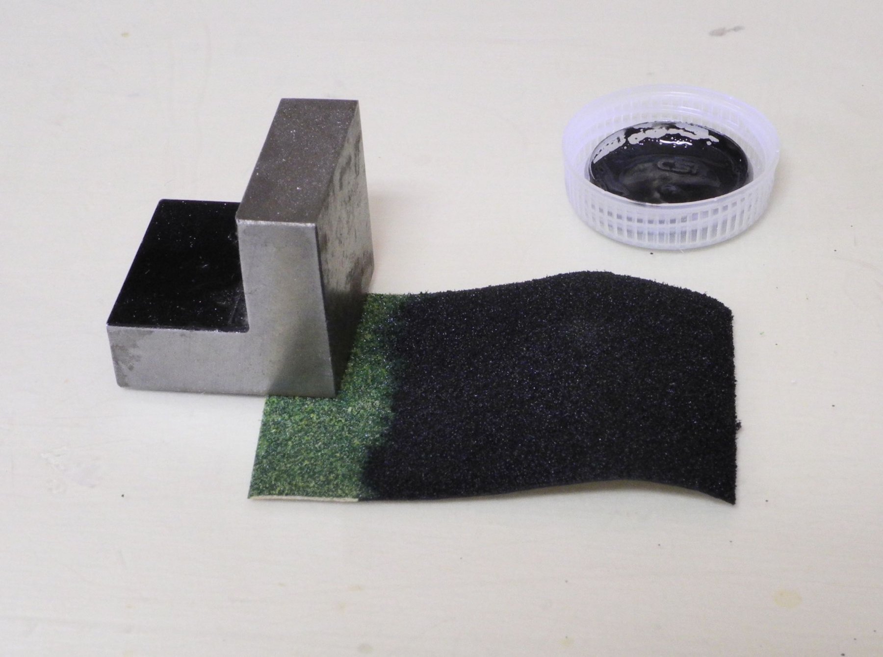
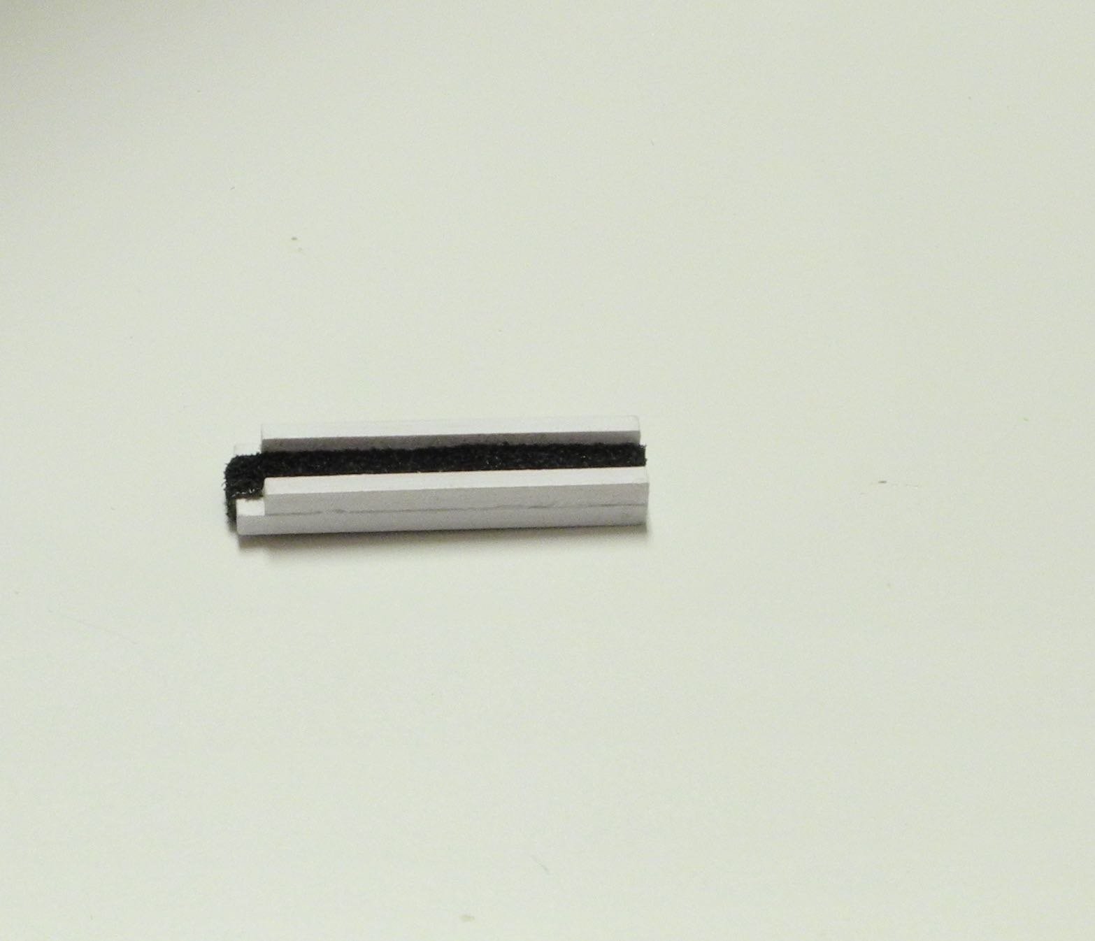
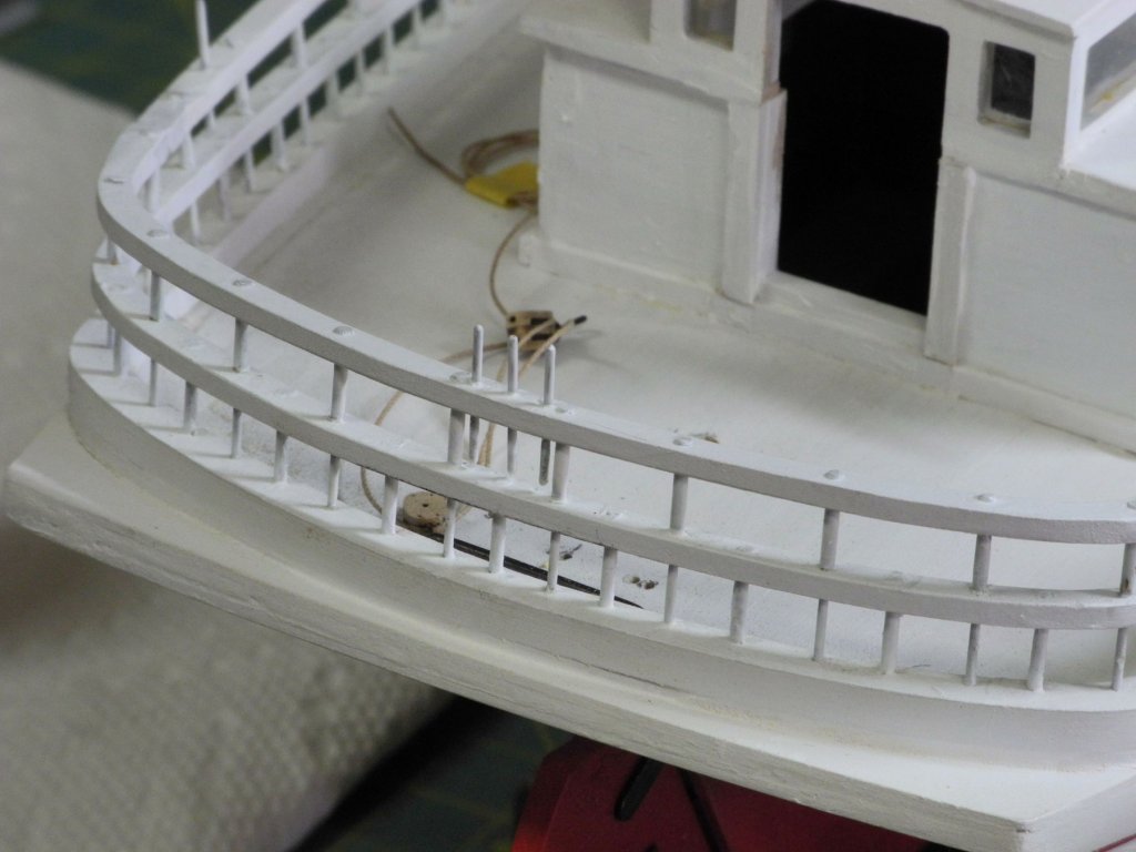
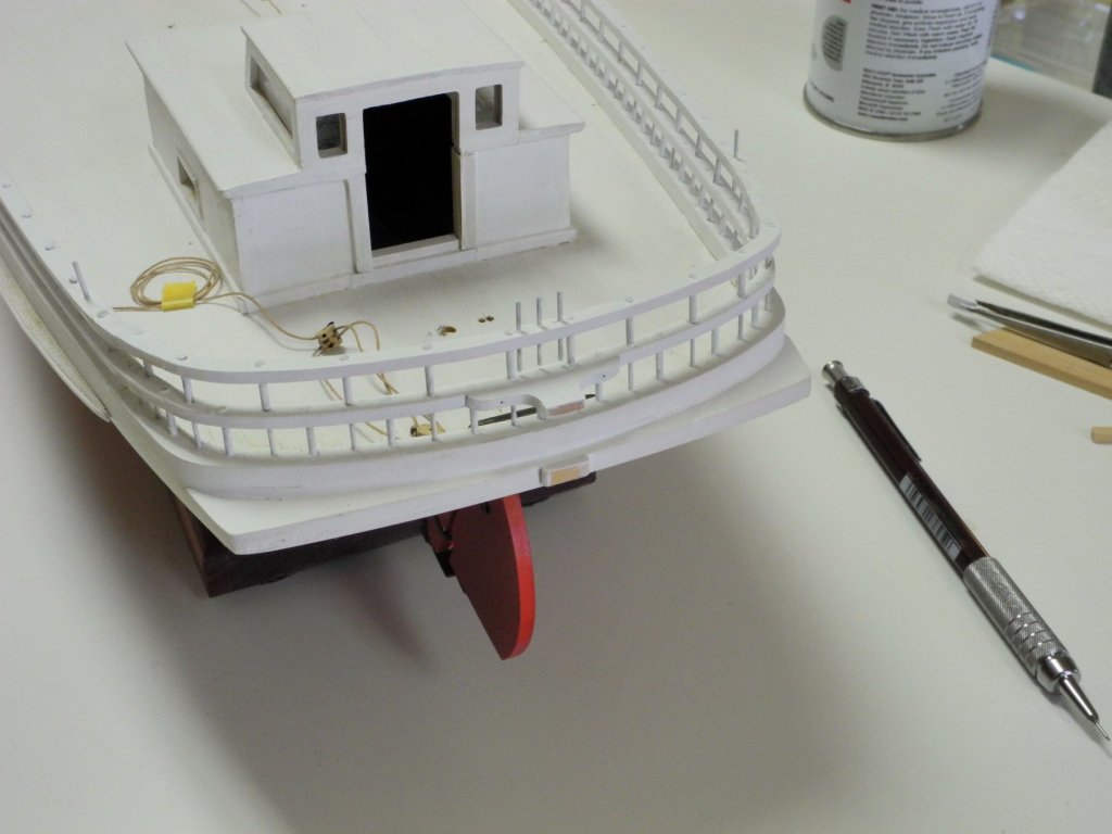
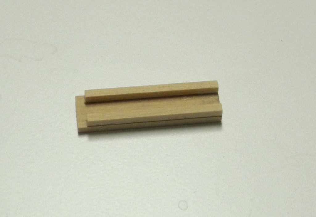
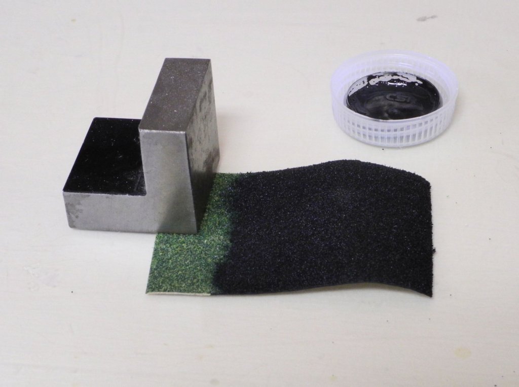
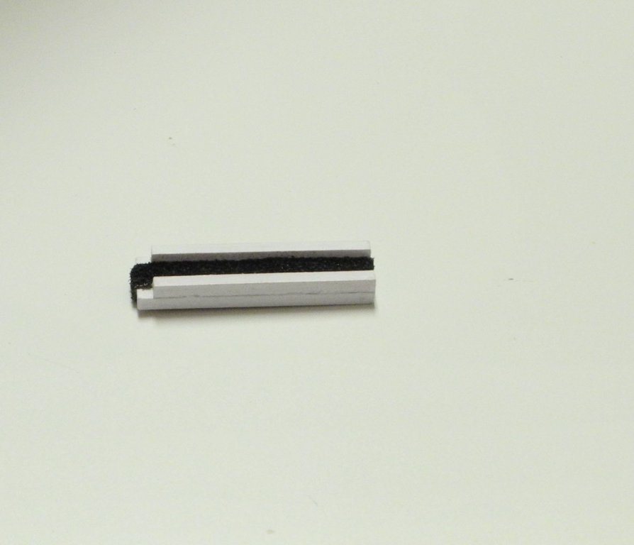
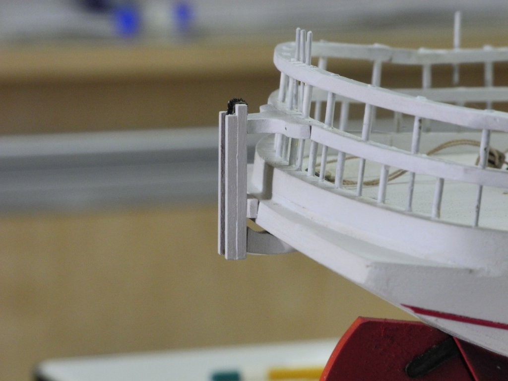
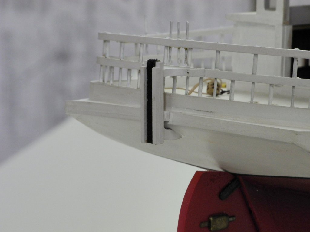
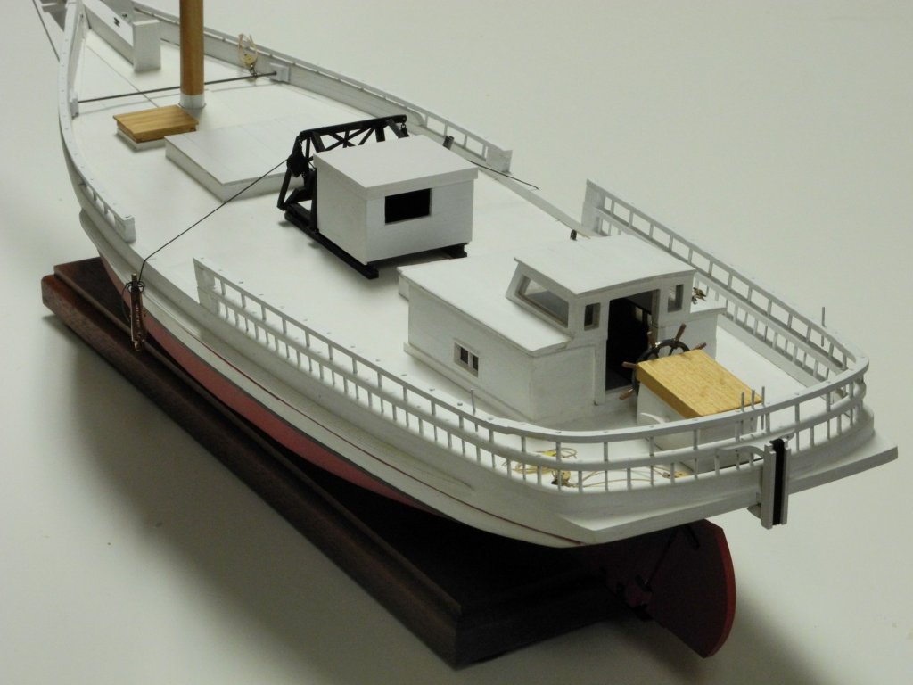
Part 56 – Push Boat Bumper When not under sail, skipjacks are maneuvered by a Yawl Boat, or Push Boat, pushing against a bumper located at the aft end of the skipjack. Since most skipjacks have an external rudder post the bumper needs to be located to the side of the transom. Kathryn, however, has an ‘inboard rudder’ with the rudder post located forward of the transom. This allows the bumper to be located in the center of Kathryn’s transom. Kathryn’s bumper is supported against the lower of the aft head rails by a curved ‘knee’, and is also mounted to the deck and to the transom below the deck. As can be seen in the above photo, there are three 1-inch iron bars mounted to the upper head rail in the center portion of Kathryn’s aft area, above the push boat bumper. There are also single bars mounted on the port and starboard rear quarter. These bars are used as belaying pins (but are not removable) for managing the ropes associated with the push boat. On the model, these pins are represented by 1/32” brass rods inserted at the appropriate locations. The knee was fabricated from wood of the same thickness as the head rails and was glued in place. A support was glued to the deck. The vertical main body of the bumper is a board with rails mounted at each side, so this was fabricated from appropriate stock. On Kathryn, the area between the vertical rails contains a strip from an old tire as a shock absorber. A piece of paper-backed felt was painted flat black to simulate the texture of an old tire. The bumper’s main body was painted, and then a strip of the ‘tire’ was glued in place. The bumper was installed on Kathryn’s aft, and the support that connects to the transom was installed. This was a relatively simple construction, but it added a nice feature to Kathryn’s aft area. Thanks everyone!

- 878 replies
-
- 16
-